Embed Size (px)
Citation preview

ENSC 427: Communication Networks
Spring 2014
THE PERFORMANCE ANALYSIS OF
LTE NETWORK http://www.sfu.ca/~jla235/427Project.html
Team 06
Guo’Enzo 301126666 [email protected]
Lin’James 301126878 [email protected]
Zhang’ Yang 301128360 [email protected]

1
Contents
Acronyms ................................................................................................................................................ 2 Table of Figures ...................................................................................................................................... 2 Table of Tables ........................................................................................................................................ 2 Abstract ................................................................................................................................................... 3 1. Introduction ......................................................................................................................................... 4 2. Background ......................................................................................................................................... 5
2.1 Overview of LTE Network Architecture ....................................................................................... 5 2.2 E-UTRAN ..................................................................................................................................... 6 2.3 EPC ............................................................................................................................................... 6
2.3.1 MME ...................................................................................................................................... 6 2.3.2 HSS ........................................................................................................................................ 6 2.3.3 PCRF ...................................................................................................................................... 6 2.3.4 PDN-GW ................................................................................................................................ 6 2.3.5 S-GW ..................................................................................................................................... 6
3. Main Parameters ................................................................................................................................. 7 3.1 Jitter............................................................................................................................................... 7 3.2 End-to-End Delay ......................................................................................................................... 7 3.3 LTE Delay ..................................................................................................................................... 7 3.4 Throughput .................................................................................................................................... 7 3.5 MOS .............................................................................................................................................. 7
4. OPNET Implementation...................................................................................................................... 8 4.1 Overview of LTE Model in OPNET ............................................................................................. 8 4.2 OPNET Simulation Topology ....................................................................................................... 8 4.3 Voice over IP (VoIP) on LTE Configuration ................................................................................. 8 4.4 Web Browsing on LTE Configuration ........................................................................................... 9
5. Simulation Results ............................................................................................................................ 13 5.1 VoIP Results ................................................................................................................................ 13 5.2 Web Browsing Result .................................................................................................................. 15
6. Conclusion ........................................................................................................................................ 18 7. Future Work ...................................................................................................................................... 18 Reference .............................................................................................................................................. 19 Appendix ............................................................................................................................................... 20
LTE network parameters setup of VoIP............................................................................................. 20 HTTP server parameters setup: ......................................................................................................... 21

2
Acronyms 3GPP 3rd Generation Partnership Project
EPC Evolved Packet Core
GSM Global System for Mobile
HTTP Hypertext Transfer Protocol
IP Internet Protocol
ITU International Telecommunication Union
LTE Long Term Evolution
MOS Mean opinion score
VoIP Voice over Internet Protocol
QoS Quality of Service
UMTS Universal Mobile Telecommunication System
Table of Figures Figure 1 LTE Network Architecture ........................................................................................................ 5
Figure 2 Functions of E-UTRAN and EPC ............................................................................................. 5
Figure 3 OPNET VoIP over LTE Design (500m) .................................................................................... 8
Figure 4 VoIP Configuration Parameters ................................................................................................ 9
Figure 5 Scenarios for different distances ............................................................................................. 10
Figure 6 Scenarios for different number of users .................................................................................. 10
Figure 7 Web http configuration parameters ......................................................................................... 11
Figure 8 Web server page setup ............................................................................................................ 11
Figure 9 Page size setup ........................................................................................................................ 12
Figure 10 Jitter result for VoIP .............................................................................................................. 13
Figure 11 End-to-end delay result for VoIP .......................................................................................... 14
Figure 12 MOS result for VoIP ............................................................................................................. 14
Figure 13 Delay of various distances .................................................................................................... 15
Figure 14 Throughput of various distances ........................................................................................... 16
Figure 15 LTE Delay of Multi-user ....................................................................................................... 16
Figure 16 Throughput of Multi-user ..................................................................................................... 17
Table of Tables Table 1 ITU Standard for MOS ............................................................................................................... 7

3
Abstract
Long Term Evolution (LTE) is a standard for wireless data communications technology.
LTE is the evolution of GSM/UTMS network technologies with increased capacity and
speed using packet switched radio interface. It is widely used by many countries as the
latest high speed mobile broadband technology; however, the main stream telephony
services of the world, such as GSM, UMTS and CDMA2000, are circuit switched radio
interface, so in order to adopt the LTE standard, the mobile voice services will shift from
circuit switched to packet switched mode using the VoIP services.
This paper focuses on the quality of service (QoS) of Voice over IP (VoIP) and Web
Browsing on the LTE network, which includes the analysis of End to End Delay, LTE
delay, Mean Opinion Score (MOS) and Throughput. Moreover, this paper provides a
detailed description of simulation models for network topology and elements using
OPNET 16.0.

4
1. Introduction
Nowadays, people’s life is closely related to mobile devices and the demand for high
speed reliable mobile becomes increasingly strong. The 4th
Generation (4G) – LTE is
developed by 3rd
Generation Partnership Project (3GPP) as the evolution of GSM/UTMS
standards. Compare to 2nd
Generation (2G) and 3rd
Generation (3G) Networks; LTE has a
significantly increased data rate: the designed maximum peak data rate for Downlink
(DL) is 100 Mbps and peak data rate for Uplink (UL) is 50 Mbps. LTE also has the
increased spectrum flexibility, the supported bandwidth is optimized from 1.4 MHz to 20
MHz. The core network of LTE is purely designed and optimized for packet switched
radio interface, which means LTE network is not compatible with circuit switched
network, such as GSM and UMTS.
Voice is the basic communication service which is well implemented in the circuit
switched networks, by introduction of LTE network, voice service is shifted to packed
switched mode from circuit switched mode and VoIP is applied to the network. VoIP
convert the voice signal to digital packet and transfer the voice data via packed switched
system. The biggest advantage of VoIP is that the cost of voice service is significantly
decreased and this is a flexible voice solution for users; however, the QoS of VoIP
depends on the network condition. If the network connection is slow, the voice quality
will be poor and not behave in timely manner. Thus, we want to analysis the performance
of VoIP on LTE network.
Moreover, the biggest advantage of LTE network is that LTE has the highest data rate.
Mobile users can benefit from the high data rate and enjoy the mobile web browsing
experience. We want to discover the performance of web browsing on LTE network.
In order to analyze the performance of VoIP and Web browsing on LTE network, we
focus and analyze the following parameters:
Jitter
End-to-end delay
LTE delay
Throughput
Mean Opinion Score (MOS)
With the simulation results, we will determine the performance of LTE network and
discover the factors which can affect the performance.

5
2. Background
In this section, the background information of LTE network architecture will be
demonstrated.
2.1 Overview of LTE Network Architecture Figure 1 shows the architecture of LTE network. The LTE network architecture is called
Evolved Packet System (EPS). EPS is an IP based architecture and provides IP users
connectivity to packet data network. From the high level view, EPS contains 2 major
parts: Evolved Universal Terrestrial Radio Access Network (E-UTRAN) and Evolved
Packet Core (EPC).
Figure 1 LTE Network Architecture
Figure 2 Functions of E-UTRAN and EPC

6
2.2 E-UTRAN E-UTRAN only contains one node, the evolved NodeB (E-NodeB), which is connected to
the user equipment (UE). E_UTRAN is connected to EPC via S1 layer. The E-NodeB is
responsible in scheduling and optimization of user radio resource. Due to the self-control
functionality, E-NodeB allows low response time.
2.3 EPC EPC contains 5 logic nodes: Mobility Management Entity (MME), Home Subscriber
Server (HSS), Proxy and Charging Rules Function (PCRF), Packet Data Network
Gateway (PDN-GW) and Serving Gateway (S-GW). The detailed information of these
nodes will be explained in the following sections.
2.3.1 MME
MME controls the plane signaling between user and EPC. The Non Access Stratum
(NAS) protocol is running between UE and EPC.
2.3.2 HSS
HSS is a database containing all the related information of user and subscriber. It is
responsible for providing support functions in mobility management, call setup, user
authentication and access authorization.
2.3.3 PCRF
The main responsibility of the PCRF is performing the Policy and Charging Control (PCC)
functions that are used to control the QoS configuration and tariff making of each individual
user. PCRF also gives the specified tariff and QoS policies of each UE to the PDN-GW and
the S-GW.
2.3.4 PDN-GW
The PDN-GW acts as an interface point of interconnect between EPC and external packet
data networks. UE is allowed to have simultaneous multi-connectivity with different
PDN-GW. The PDN-GW is responsible for establishing, maintaining and deleting the
GPRS Tunneling Protocol (GTP) tunnels to S-GW. It is also responsible for performing
IP address allocation, policy control, packet filtering for each user, charging, lawful
Interception and packet screening.
2.3.5 S-GW
The SGW is responsible for routing and forwarding the data packets between users and
E-NodeB. It produces a tunnel to transmit data traffic between the UE and external
network. It is also responsible for acting as the mobility anchor for the user plane
between inter- E-NodeB handover and as the anchor moves between LTE and other 3GPP
technologies.
7
3. Main Parameters In order to analyze the QoS of VoIP and web browsing on LTE network, we will focus on
the follow parameters when analyzing the simulation results.
3.1 Jitter In packet switched networks, packets are received in continuous streams and jitter is
defined as the variation in time between each receiving. Jitter is the result of congesting
in the IP network, which can occur at receiver side or carrier network. Jitter is a very
important parameter in voice streaming because jitter can lead to poor voice quality and
the level of jitter should be minimized. The level of jitter can be reduced by adding anti-
jitter circuits, jitter buffers, dejitterizer, and filtering. According to International
Telecommunication Union (ITU) standard, the average jitter should be less than 60ms
and the ideal jitter should be less than 20ms.
3.2 End-to-End Delay End-to-end delay is defined as the time for a packet to be transmitted from the source to
the destination. The end-to-end delay is related to encoding/decoding delay, transmission
delay, propagation delay, processing delay and queen delay. The end-to-end delay is an
important parameter for real-time transmission because we want the voice stream is
transmitted in the timely manner. According to ITU standard, the average end-to-end
delay should be less than 150ms and the ideal end-to-end delay should be less than 50ms.
3.3 LTE Delay LTE delay is the round-trip delay, which is the time from a packet is send to the
acknowledgement is received. This delay is related to the distance between the user and
base station, number of users and the applications (VoIP/web browsing).
3.4 Throughput Throughput is the data rate that is successfully delivered over a channel. The unit for
throughput is usually bits per second. By comparing the throughput of each scenario, it is
easy to determine the QoS of each scenario.
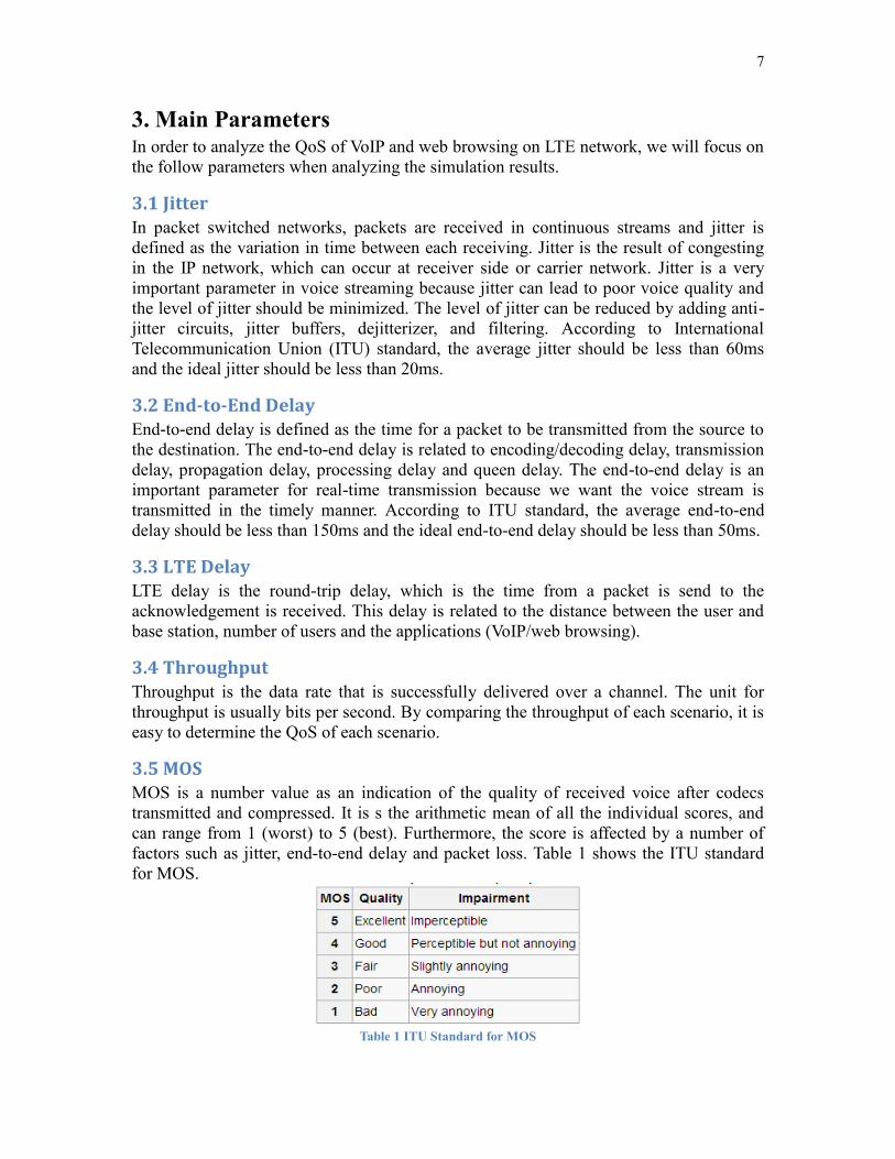
3.5 MOS MOS is a number value as an indication of the quality of received voice after codecs
transmitted and compressed. It is s the arithmetic mean of all the individual scores, and
can range from 1 (worst) to 5 (best). Furthermore, the score is affected by a number of
factors such as jitter, end-to-end delay and packet loss. Table 1 shows the ITU standard
for MOS.
Table 1 ITU Standard for MOS

8
4. OPNET Implementation
4.1 Overview of LTE Model in OPNET The OPNET contains a large capacity models library that supports various protocols like
TCP, UDP, SIP and it is capable of simulating applications like voice, FTP, web browsing
etc. Moreover, the OPNET model has a hierarchical environment which is composted of
the network model, node model and process model. All the three models need to be
configured to perform the simulation. The LTE network model in OPNET is consisted of
mobile nodes, an E-Node B and an EPC.
4.2 OPNET Simulation Topology In this project, it contains two test cases for analyzing the performance of LTE network.
First network, we simulated the Voice over IP (VoIP) in different distance and compared
their result. Second network, we simulated the web browsing in different distance and
number of IP user to analyze their result.
4.3 Voice over IP (VoIP) on LTE Configuration In the VoIP configuration, we design two scenarios in different distance and we set
eNodeB is equidistant from the two mobile users in both scenarios: one setting mobile
users and eNodeB are 500 meters and one setting mobile users and eNodeB are 1000
meters.
Figure 3 OPNET VoIP over LTE Design (500m)
Figure3 is the topology of our first scenario. We used the OPNET Application Definition
attribute to set up the VoIP model and the VoIP Configuration parameter show in Figure 3

9
below. The VoIP application uses G.711 encoder scheme and Interactive Voice (6) as the
type of service for creating the VoIP calls. After configuring the application, we was
going to configure the Profile definition by using Profile Definition attribute. It set the
start time of the simulation to 100 (off-set “60”+start time “40”) seconds and the VoIP
application is repeated continuously until the end of the simulation. It implied that VoIP
calls will be established between source and destination starting at 100 seconds and the
calls are added continuously until the end of simulation. Then, we chose 20MHz
bandwidth in the e-NodeB. Next, we created second scenario by changing the distance
between e-NodeB and mobile users.
Figure 4 VoIP Configuration Parameters
4.4 Web Browsing on LTE Configuration
The following figure is one of the topologies we implemented for the web browsing. In
this topology we are going to verify how the distance between e-NodeB and mobile
station affect the performance of the web browsing. We set the voice service as the
application. The figure below shows 3 different scenarios. Mobile users 1, 2, 3, 4 and e-
NodeB are kept at the same position and the distance between mobile user 5 and e-
NodeB is changed as 500m, 1km and 1.5km. We are going to analyze the effect of
distance through the parameters: LTE delay and throughput.

10
Figure 5 Scenarios for different distances
The following figure is the topologies we implemented to test the effect of number of mobile
users in the same LTE network for the web browsing. We have the HTTP web browsing as
the application and add the HTTP server to the LTE network. The topology contains shows 3
different scenarios. We kept 4 mobile users in the first scenario, 8 mobile users in the second
scenario, and 16 mobile users in the third scenario. We are going to analyze the effect of
number of mobile users through the parameters: LTE delay and throughput.
Figure 6 Scenarios for different number of users

11
Figure 7 Web http configuration parameters
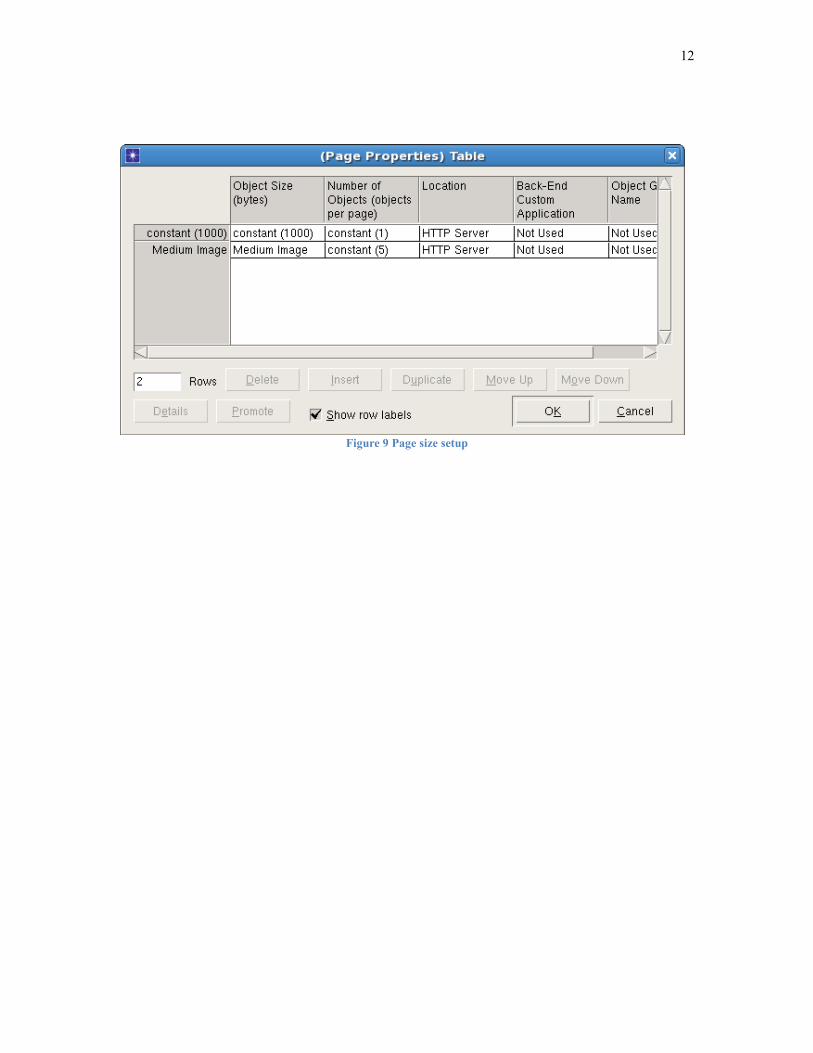
The above figure is the configuration parameter we set in the web http application. HTTP
1.1 is set as the HTTP Specification. Page Intertribal Time is set to be 10 seconds
constantly. The page is set to be the combination of constant 1000 and medium image. As
the figure 8 shows below:
Figure 8 Web server page setup
12
Figure 9 Page size setup
13
5. Simulation Results
5.1 VoIP Results
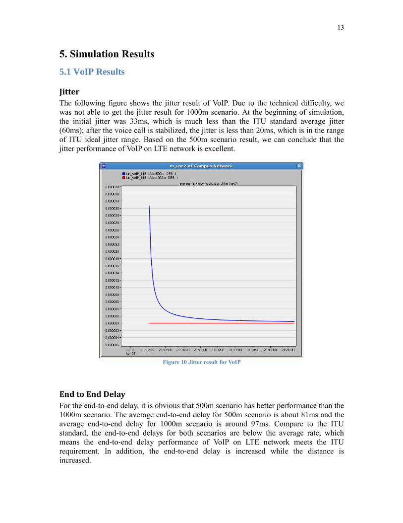
Jitter
The following figure shows the jitter result of VoIP. Due to the technical difficulty, we
was not able to get the jitter result for 1000m scenario. At the beginning of simulation,
the initial jitter was 33ms, which is much less than the ITU standard average jitter
(60ms); after the voice call is stabilized, the jitter is less than 20ms, which is in the range
of ITU ideal jitter range. Based on the 500m scenario result, we can conclude that the
jitter performance of VoIP on LTE network is excellent.
Figure 10 Jitter result for VoIP
End to End Delay
For the end-to-end delay, it is obvious that 500m scenario has better performance than the
1000m scenario. The average end-to-end delay for 500m scenario is about 81ms and the
average end-to-end delay for 1000m scenario is around 97ms. Compare to the ITU
standard, the end-to-end delays for both scenarios are below the average rate, which
means the end-to-end delay performance of VoIP on LTE network meets the ITU
requirement. In addition, the end-to-end delay is increased while the distance is
increased.

14
Figure 11 End-to-end delay result for VoIP
MOS
As figure 12 shows, the MOS for 500m scenario and 1000m scenario is 3.59 and 3.48
respectively. Based on the ITU standard, the voice quality is in the range fair to good. It is
obvious that MOS is related to the distance of user, shorter distance can lead to better
MOS.
Figure 12 MOS result for VoIP

15
5.2 Web Browsing Result
LTE Delay of Various Distances
In the figure below, the blue line shows the LTE delay of the 500 meter scenario, the red line
shows the result for 1000m scenario and green line shows result of 1500m scenario. It is
obvious that the shorter distance between users and eNodeB can lead to the shorter LTE
Delay. At the beginning of simulation, the 500m scenario has the best initial delay of the
3 scenarios. Then the LTE delay of these 3 scenarios starts to decrease. The final average
LTE delay for 500m scenario is about 1.55ms and the final average LTE delay for 1500m
scenario is around 1.57ms. When these 3 scenarios reach the stable, the delay of the
500m is still the lowest one.
Figure 13 Delay of various distances
Throughput of various distances
Based on the maximum throughput value in figure 14, the maximum throughput for 500
meters, 1000 meters and 1500 meters are 3100 bits/sec, 3050 bits/sec and 3000 bits/sec,
respectively. It is obvious that the shorter distance between users and eNodeB can lead to
larger maximum throughput. This is what we expected.

16
Figure 14 Throughput of various distances
LTE Delay of various number of IP user
In the figure below, the blue line shows the LTE delay of the scenario which contains 4 IP
users while red and green lines show other two scenarios which contain 8 IP users and 16 IP
users, respectively. It is obvious that increasing the number of IP user can increase the
LTE Delay value. The average LTE delay for 4-user scenario, 8-user scenario and 16-user
scenario are 1.75ms, 1.78ms and 1.79ms, respectively.
Figure 15 LTE Delay of Multi-user

17
Throughput of various number of IP user
The figure for multi-user throughput is shown below, it is obvious that the green line,
which is the throughput of 16-user scenario, has the largest maximum throughput value
and 4-user scenario has the smallest maximum throughput value. The maximum
throughput for 4-user scenario, 8-user scenario and 16-user scenario are 2200 bits/sec,
2300 bits/sec and 2800 bits/sec, respectively.
Figure 16 Throughput of Multi-user

18
6. Conclusion For voice over IP on LTE, the results of OPNET simulation agree with theory. There is
increment in End-to-End delay when the distance between users and eNodeB is increased.
Moreover, the MOS value is decreased as we the increase the distance between users and
eNodeB. In other word, when the distance between the users and eNodeB decreased, the
quality of VoIP decreased.
For Web Browsing on LTE, it is obvious that the increment in the distance between users
and eNodeB and the increment in number of IP users will increase the LTE Delay value
and maximum throughput. Therefore, we can conclude that in the same network, the
fewer users or the closer the user beside the eNodeB, the better internet browsing
performance.
7. Future Work For this project, we analyzed the performance of VoIP and Web Browsing on one single
cell LTE network. In order to make the simulation more reliable, we can simulate the
VoIP and Web Browsing data transmit on multi-cell LTE network in future. Furthermore,
we can also simulate VoIP and Browsing work in different network, such as WIFI and
WIMAX, and then compare the simulation results with what we did on LTE network. In
addition, we only modulated VoIP or Web Browsing traffic model to analyze the
performance of LTE network. We can combine various applications together on LTE
network and analyze the effect to the performance.

19
Reference [1]Alcatel-Lucent Inc. “The LTE Network Architeture”. 2009(online).
Available:
http://www.cse.unt.edu/~rdantu/FALL_2013_WIRELESS_NETWORKS/LTE_Alcatel_
White_Paper.pdf
[2]B. Furht and Syed A. Ahson, "Long Term Evolution: 3GPP LTE Radio And Cellular
Technology", Crc Press, 2009
[3]Cisco systems Inc. “Understanding Codecs: Complexity, Hardware Support, MOS,
and Negotiation”. Feb 02, 2006 (online).
Available:
http://www.cisco.com/en/US/tech/tk1077/technologies_tech_note09186a00800b6710.sht
ml#mos
[4]Cisco systems Inc. “Understanding Jitter in Packet Voice Networks (Cisco IOS
Platforms)”. Feb 02, 2006 (online). Available:
http://www.cisco.com/c/en/us/support/docs/voice/voice-quality/18902-jitter-packet-
voice.html
[5]D.Sahota. “LTE falls back on voice”. Sep 10, 2013 (online).
Available: http://www.telecoms.com/177492/lte-falls-back-on-voice/
[6]G. Camarillo and M. Garcia-Martin. “The 3G IP Multimedia Subsystem(IMS):
Merging the Internet and the Cellular Worlds”, 2006.
[7]Kurose, J. F. & Ross, K. W. (2010) Computer Networking: A Top-Down Approach.
New York: Addison-Wesley. P 30
[8]S. Sesia, I. Toufik, and M. Baker, "LTE – The UMTS Long Term Evolution – From
Theory to Practice". Second Edition including Release 10 for LTE-Advanced, John Wiley
& Sons, 2011
[9]P.Guraauraj. “Masters Thesis: Voice over LTE”. Jun 29, 2012 (online).
Available: http://repository.tudelft.nl/assets/uuid:a1ee990a-31bc-4f8b-9e27-
0b0617e5a08f/Msc_Thesis_Report_Prasanna_Gururaj.pdf
[10]The Mobile Broadband Standard, 3GPP TS 22.173, IP Multimedia Core Network
Subsystem (IMS) Multimedia Telephony Service and supplementary services; Stage 1
[11]Torad, Mohammad, Dr. "Comparison between L TE and WiMAX Based on System
Level Simulation Using OPNET Modeler (release 16)." 28 Th NATIONAL RADIO
SCIENCE CONFERENCE (2011): n. pag. Print.

20
Appendix
LTE network parameters setup of VoIP

21
HTTP server parameters setup: