Embed Size (px)
Citation preview
THE PENNSYLVANIA STATE UNIVERSITYDEPARTMENT OF ARCHITECTURAL ENGINEERING
WOOD REDESIGN OF THE ADDITION TO 11141 GEORGIA AVENUE, WHEATON, MD
SAMANTHA DEVRIESSPRING 2015
A thesissubmitted in partial fulfillment
of the requirementsfor a baccalaureate degree
in Architectural Engineering
Thesis Advisor: Thomas E. Boothby
Structural Option

11141 Georgia Avenue: High Rise Residential Apartments Located in: Wheaton, MD
Building Statistics Full Height: 158 Feet Number of Stories: 14 Size: 179,760 GSF Square Feet Cost: $44 Million (for the addition) Construction Dates: February 2013 - August 2014 Project Delivery Method: Contractor at Risk Project Team Owner: ML Wheaton, LLC c/o Lower Enterprises General Contractor and CM: Whiting-Turner Architect: Bonstra Haresign Architects, LLP Structure: Rathgeber/Goss Associates Mechanical: Brothers Ductwork HVAC, Inc. Plumbing: KNI Engineering, Inc. Lighting Design: Gilmore Lighting Design
Samantha deVries: Structural Option Project Sponsor: Rathgeger/Goss Associates Advisor: Ali Said https://www.engr.psu.edu/ae/thesis/portfolios/2015/sjd5225/deVries_AE_Thesis/Home.html
Architecture 5 story 1960’s office building 7 story addition High rise apartment building with one and two
bedroom studios. Construction Underpin Foundations Renovations work in existing building Construct addition directly above existing Mechanical Cooling by rooftop chiller condensing units Units have occupant operable windows Heating by electrical heaters and heat pumps. Electrical/Lighting Recessed lighting in apartments Pendant and wall mounted fixtures in lobbies 2 Main Power Distributers fed from a transformer One 1400 KVA and one 1750 KVA
Structural Systems Original Concrete Building Concrete moment frames Concrete floor slabs Spread footings and retaining walls
New Addition Steel moment frames Lightweight composite floor joists with deck
Loads Original loads for office building New live loads smaller for residential
Renovation Work New stairwell and elevator locations New utility openings Façade modifications
Photo of typical apartment: Photo courtesy of The George (Apartment)
Photo of building from nearby parking garage roof: Photo taken by Samantha deVries
Photo of rooftop terrace: Photo courtesy of The George (Apartment)

Executive Summary
The building located at 11141 Georgia Avenue in Wheaton, Maryland was recently renovatedinto an apartment building, finishing construction in August of 2014. The original buildingwas a 7 story concrete o�ce building. A 7 story addition was added on top of the existingstructure in joist-framed steel, and the concrete portion of the building was renovated to meetnew architectural needs.
The following report includes the methods and processes used in the analysis and redesign ofthe addition. Both the gravity and lateral systems were analyzed in the redesigned system. Alsoincluded is breadth work in the topics of construction management and mechanical.
In order to keep the addition lightweight to minimize e�ects on the existing system, wood waschosen for the redesign. Although wood construction does not currently meet code US for the 7story addition, the report discusses the research regarding taller wood buildings and the use ofwood in taller buildings in other countries. A purpose of the report was to discover whether ornot a wood addition would be feasible in the case of 11141 Georgia Ave.
A panel product called Cross Laminated Timber was used for the floors, which spans a full baybetween girders. Glulam is used for the girders and columns. The gravity system was designedfor flexure, deflections, fire performance, and connections for use with dyrwall encapsulation. Fireperformance calculations were completed with the assumption that all wood structural elementswill be encapsulated with a single layer of drywall.
The lateral system included several concrete shear walls to resist wind loading, the controllinglateral case over seismic. ETABS was used to complete the lateral system design. Several methodswere used to validate the model.
The topics of construction management and mechanical systems were also explored in thisreport. The construction breadth determined that the redesigned system is competitive with theexisting system when considered both cost and schedule. The wood redesign cannot have enclosedspaces, and thus new mechanical system was chosen to improve the aesthetics of the equipmentin each apartment.
After completing the wood redesign, it was found that the wood alternate is structurallyfeasible as an addition. There are both challenges and benefits to using wood in the addition.Although there are several challenges with regards to fire safety, research has shown that heavytimber can meet safety requirements. Finally, the wood redesign does not add too much costconsidering it significantly reduces the schedule, and it is a very lightweight structure.
ii

Table of Contents
List of Figures v
List of Tables vii
Acknowledgments viii
Chapter 1Introduction 11.1 Existing Building . . . . . . . . . . . . . . . . . . . . . . . . . . . . . . . . . . . . 1
1.1.1 Structural Systems Overview . . . . . . . . . . . . . . . . . . . . . . . . . 21.1.2 Foundations . . . . . . . . . . . . . . . . . . . . . . . . . . . . . . . . . . . 31.1.3 Gravity System . . . . . . . . . . . . . . . . . . . . . . . . . . . . . . . . . 31.1.4 Lateral System . . . . . . . . . . . . . . . . . . . . . . . . . . . . . . . . . 6
1.2 Load Analysis . . . . . . . . . . . . . . . . . . . . . . . . . . . . . . . . . . . . . . 71.2.1 Gravity Loads . . . . . . . . . . . . . . . . . . . . . . . . . . . . . . . . . 71.2.2 Lateral Loads . . . . . . . . . . . . . . . . . . . . . . . . . . . . . . . . . . 9
1.3 Thesis Problem Statement . . . . . . . . . . . . . . . . . . . . . . . . . . . . . . . 111.3.1 Justification for Design Approach . . . . . . . . . . . . . . . . . . . . . . . 121.3.2 Proposed Solution . . . . . . . . . . . . . . . . . . . . . . . . . . . . . . . 131.3.3 Solution Method . . . . . . . . . . . . . . . . . . . . . . . . . . . . . . . . 13
Chapter 2Heavy Timber Construction 152.1 Introduction . . . . . . . . . . . . . . . . . . . . . . . . . . . . . . . . . . . . . . . 152.2 Heavy Timber Defined . . . . . . . . . . . . . . . . . . . . . . . . . . . . . . . . . 15
2.2.1 Benefits of Heavy Timber . . . . . . . . . . . . . . . . . . . . . . . . . . . 162.2.2 Challenges of Heavy Timber . . . . . . . . . . . . . . . . . . . . . . . . . . 17
2.3 Environmental Impact . . . . . . . . . . . . . . . . . . . . . . . . . . . . . . . . . 172.3.1 E�ects on Climate Change . . . . . . . . . . . . . . . . . . . . . . . . . . 172.3.2 Life Cycle Analysis . . . . . . . . . . . . . . . . . . . . . . . . . . . . . . . 18
2.4 Fire-Safety . . . . . . . . . . . . . . . . . . . . . . . . . . . . . . . . . . . . . . . 202.4.1 Heavy Timber Fire Resistance . . . . . . . . . . . . . . . . . . . . . . . . 202.4.2 Code With Respect to Fire Safety . . . . . . . . . . . . . . . . . . . . . . 212.4.3 Topics requiring further study and research . . . . . . . . . . . . . . . . . 22
2.5 Additional Considerations . . . . . . . . . . . . . . . . . . . . . . . . . . . . . . . 242.5.1 Vibration Performance . . . . . . . . . . . . . . . . . . . . . . . . . . . . . 242.5.2 Sound Insulation . . . . . . . . . . . . . . . . . . . . . . . . . . . . . . . . 252.5.3 Envelope Design . . . . . . . . . . . . . . . . . . . . . . . . . . . . . . . . 262.5.4 Construction Challenges . . . . . . . . . . . . . . . . . . . . . . . . . . . . 26
2.6 Literature Review . . . . . . . . . . . . . . . . . . . . . . . . . . . . . . . . . . . 272.7 Application to 11141 Georgia Ave . . . . . . . . . . . . . . . . . . . . . . . . . . . 302.8 Conclusions . . . . . . . . . . . . . . . . . . . . . . . . . . . . . . . . . . . . . . . 32
iii

Chapter 3Structural Redesign 333.1 Introduction . . . . . . . . . . . . . . . . . . . . . . . . . . . . . . . . . . . . . . . 333.2 Gravity System . . . . . . . . . . . . . . . . . . . . . . . . . . . . . . . . . . . . . 33
3.2.1 CLT Floor Panel Design . . . . . . . . . . . . . . . . . . . . . . . . . . . . 333.2.2 Glulam Girder Design . . . . . . . . . . . . . . . . . . . . . . . . . . . . . 373.2.3 Glulam Column Design . . . . . . . . . . . . . . . . . . . . . . . . . . . . 413.2.4 Typical Opening Design . . . . . . . . . . . . . . . . . . . . . . . . . . . . 433.2.5 Concrete Bearing Walls . . . . . . . . . . . . . . . . . . . . . . . . . . . . 443.2.6 Gravity System Conclusions and Design Summary . . . . . . . . . . . . . 44
3.3 Lateral System . . . . . . . . . . . . . . . . . . . . . . . . . . . . . . . . . . . . . 473.3.1 Modeling Approach and Assumptions . . . . . . . . . . . . . . . . . . . . 473.3.2 Model Behavior . . . . . . . . . . . . . . . . . . . . . . . . . . . . . . . . . 493.3.3 Shear Wall Design . . . . . . . . . . . . . . . . . . . . . . . . . . . . . . . 503.3.4 Lateral System Conclusions and Design Summary . . . . . . . . . . . . . 55
3.4 Structural Redesign Conclusions . . . . . . . . . . . . . . . . . . . . . . . . . . . 55
Chapter 4Construction Breadth 594.1 Introduction . . . . . . . . . . . . . . . . . . . . . . . . . . . . . . . . . . . . . . . 594.2 Schedule Analysis . . . . . . . . . . . . . . . . . . . . . . . . . . . . . . . . . . . . 59
4.2.1 Existing Addition . . . . . . . . . . . . . . . . . . . . . . . . . . . . . . . . 594.2.2 Redesigned Wood Addition . . . . . . . . . . . . . . . . . . . . . . . . . . 604.2.3 Schedule Comparison . . . . . . . . . . . . . . . . . . . . . . . . . . . . . 60
4.3 Cost Analysis . . . . . . . . . . . . . . . . . . . . . . . . . . . . . . . . . . . . . . 614.3.1 Existing Addition . . . . . . . . . . . . . . . . . . . . . . . . . . . . . . . . 614.3.2 Redesigned Wood Addition . . . . . . . . . . . . . . . . . . . . . . . . . . 624.3.3 Cost Comparison . . . . . . . . . . . . . . . . . . . . . . . . . . . . . . . . 63
4.4 Conclusions . . . . . . . . . . . . . . . . . . . . . . . . . . . . . . . . . . . . . . . 64
Chapter 5Mechanical Breadth 655.1 Introduction . . . . . . . . . . . . . . . . . . . . . . . . . . . . . . . . . . . . . . . 655.2 Exposed Mechanical Systems . . . . . . . . . . . . . . . . . . . . . . . . . . . . . 65
5.2.1 Case Studies . . . . . . . . . . . . . . . . . . . . . . . . . . . . . . . . . . 655.2.2 Design Guidelines . . . . . . . . . . . . . . . . . . . . . . . . . . . . . . . 665.2.3 Mechanical Layout Redesign . . . . . . . . . . . . . . . . . . . . . . . . . 67
5.3 Conclusions . . . . . . . . . . . . . . . . . . . . . . . . . . . . . . . . . . . . . . . 70
Chapter 6Conclusions 716.1 Summary . . . . . . . . . . . . . . . . . . . . . . . . . . . . . . . . . . . . . . . . 716.2 Heavy Timber in the Redesign . . . . . . . . . . . . . . . . . . . . . . . . . . . . 71
Appendix AGravity System Calculations 73A.1 Introduction . . . . . . . . . . . . . . . . . . . . . . . . . . . . . . . . . . . . . . . 73A.2 Existing Gravity System . . . . . . . . . . . . . . . . . . . . . . . . . . . . . . . . 73A.3 Wood Redesign . . . . . . . . . . . . . . . . . . . . . . . . . . . . . . . . . . . . . 79
A.3.1 CLT Panel Calculations . . . . . . . . . . . . . . . . . . . . . . . . . . . . 79A.3.2 Girder Calculations . . . . . . . . . . . . . . . . . . . . . . . . . . . . . . 81A.3.3 Column Calculations . . . . . . . . . . . . . . . . . . . . . . . . . . . . . . 83
iv

Appendix BLateral System Redesign Calculations 87B.1 Introduction . . . . . . . . . . . . . . . . . . . . . . . . . . . . . . . . . . . . . . . 87B.2 Existing Lateral System . . . . . . . . . . . . . . . . . . . . . . . . . . . . . . . . 87
B.2.1 Wind Loads . . . . . . . . . . . . . . . . . . . . . . . . . . . . . . . . . . . 87B.2.2 Seismic Loads . . . . . . . . . . . . . . . . . . . . . . . . . . . . . . . . . . 92
B.3 Wood Redesign . . . . . . . . . . . . . . . . . . . . . . . . . . . . . . . . . . . . . 95
Appendix CDesign Tables 99C.1 Introduction . . . . . . . . . . . . . . . . . . . . . . . . . . . . . . . . . . . . . . . 99
Appendix DBreadth Calculations 102D.1 Introduction . . . . . . . . . . . . . . . . . . . . . . . . . . . . . . . . . . . . . . . 102
D.1.1 Construction Management Breadth . . . . . . . . . . . . . . . . . . . . . . 102D.1.2 Mechanical Breadth . . . . . . . . . . . . . . . . . . . . . . . . . . . . . . 104
Bibliography 105
v

List of Figures
1.1 Building Location on Site . . . . . . . . . . . . . . . . . . . . . . . . . . . . . . . 11.2 View of 11141 Georgia Ave . . . . . . . . . . . . . . . . . . . . . . . . . . . . . . 21.3 Typical Original Concrete Structure Floor Plan . . . . . . . . . . . . . . . . . . . 41.4 Section through existing building showing slab thicknesses . . . . . . . . . . . . . 51.5 Section through new load bearing CMU Walls . . . . . . . . . . . . . . . . . . . . 51.6 Moment Frames shown highlighted on typical floor plan . . . . . . . . . . . . . . 61.7 Sections through Penthouse Roof and Outdoor Terrance Roof . . . . . . . . . . . 71.8 Snow Drift Diagram . . . . . . . . . . . . . . . . . . . . . . . . . . . . . . . . . . 71.9 Sections through Original Concrete and New Steel Floors . . . . . . . . . . . . . 81.10 Exterior Wall Sections . . . . . . . . . . . . . . . . . . . . . . . . . . . . . . . . . 81.11 Wind Pressures Summary . . . . . . . . . . . . . . . . . . . . . . . . . . . . . . . 101.12 Summary of Seismic forces on building . . . . . . . . . . . . . . . . . . . . . . . . 11
2.1 Heavy Timber versus Light Frame Wood Buildings Under Construction . . . . . 162.2 Di�erent Types of Engineered Wood Products . . . . . . . . . . . . . . . . . . . . 162.3 Percentage of energy consumption by sector . . . . . . . . . . . . . . . . . . . . . 182.4 Production and Growth Cycle of Wood . . . . . . . . . . . . . . . . . . . . . . . 182.5 Environmental Comparison: Wood and Other Construction Materials . . . . . . 192.6 Layers in Burning CLT Panel . . . . . . . . . . . . . . . . . . . . . . . . . . . . . 212.7 Review of Max Code story limit in various countries . . . . . . . . . . . . . . . . 212.8 Falling delaminated lamination during CLT fire testing . . . . . . . . . . . . . . . 232.9 Acoustic Wall Assembly . . . . . . . . . . . . . . . . . . . . . . . . . . . . . . . . 252.10 Acoustic Floor Assembly . . . . . . . . . . . . . . . . . . . . . . . . . . . . . . . . 262.11 Moisture Protection of CLT During Construction . . . . . . . . . . . . . . . . . . 27
3.1 Image of Structural System Used with CLT . . . . . . . . . . . . . . . . . . . . . 343.2 Spline connection options between panels . . . . . . . . . . . . . . . . . . . . . . 373.3 Connection options for rectangular girder versus inverted T . . . . . . . . . . . . 383.4 Drywall Encapsulation Method . . . . . . . . . . . . . . . . . . . . . . . . . . . . 403.5 Diagram of charring which occurs in beams . . . . . . . . . . . . . . . . . . . . . 403.6 Char pattern occurring at Panel to Girder connection . . . . . . . . . . . . . . . 413.7 Image of Typical Opening and Support . . . . . . . . . . . . . . . . . . . . . . . 433.8 Cross-sectional cut through typical opening detail . . . . . . . . . . . . . . . . . . 443.9 Floor to Floor height cross section comparison . . . . . . . . . . . . . . . . . . . 463.10 Comparison of tributary areas for both concrete column and shear wall . . . . . 483.11 Diaphragm Behavior Based on Rigidity . . . . . . . . . . . . . . . . . . . . . . . 493.12 Simplified Plan Showing X and Y Directions . . . . . . . . . . . . . . . . . . . . 503.13 ETABS model 3-D View . . . . . . . . . . . . . . . . . . . . . . . . . . . . . . . . 503.14 Lateral Forces Applied to Diaphragms due to Wind Load . . . . . . . . . . . . . 513.15 Schematic drawing of typical required shear wall reinforcement . . . . . . . . . . 523.16 Assumed Floor Lengths for In-Plane Deflection Calculations . . . . . . . . . . . . 54
vi

3.17 Beam Diagrams from the NDS . . . . . . . . . . . . . . . . . . . . . . . . . . . . 553.18 Typical Level Structural Plan . . . . . . . . . . . . . . . . . . . . . . . . . . . . . 563.19 12th Level Structural Plan . . . . . . . . . . . . . . . . . . . . . . . . . . . . . . . 573.20 Penthouse Roof Structural Plan . . . . . . . . . . . . . . . . . . . . . . . . . . . . 58
4.1 Total scheduling time required for construction of existing addition . . . . . . . . 604.2 Total scheduling time required for construction of existing addition . . . . . . . . 61
5.1 Example of exposed mechanical equipment . . . . . . . . . . . . . . . . . . . . . 665.2 Example of exposed mechanical equipment . . . . . . . . . . . . . . . . . . . . . 665.3 Sample apartment . . . . . . . . . . . . . . . . . . . . . . . . . . . . . . . . . . . 675.4 Typical Apartment Layouts showing mechanical equipment and lowered ceiling . 685.5 New Mechanical Layout; Typical Apartment . . . . . . . . . . . . . . . . . . . . . 695.6 Figure of typical VRV system layout possibilities . . . . . . . . . . . . . . . . . . 695.7 Comparison of e�ect of higher ceilings and exposed mechanical systems . . . . . 70
A.1 Roof Load Calculations . . . . . . . . . . . . . . . . . . . . . . . . . . . . . . . . 74A.2 Snow Load and Drift Calculations . . . . . . . . . . . . . . . . . . . . . . . . . . 75A.3 Floor Load Calculations . . . . . . . . . . . . . . . . . . . . . . . . . . . . . . . . 76A.4 Exterior Wall Load Calculations . . . . . . . . . . . . . . . . . . . . . . . . . . . 77A.5 Non-Typical Load Calculations . . . . . . . . . . . . . . . . . . . . . . . . . . . . 78A.6 Typical Opening Calculations . . . . . . . . . . . . . . . . . . . . . . . . . . . . . 80A.7 Typical Column Calculations at Base of Addition . . . . . . . . . . . . . . . . . . 83A.8 Typical Column Calculations at Base of Addition . . . . . . . . . . . . . . . . . . 84A.9 General Column Design Information . . . . . . . . . . . . . . . . . . . . . . . . . 85
B.1 Seismic Load Calculations . . . . . . . . . . . . . . . . . . . . . . . . . . . . . . . 92B.2 Seismic Load Calculations . . . . . . . . . . . . . . . . . . . . . . . . . . . . . . . 93B.3 Shear Wall Spot Check . . . . . . . . . . . . . . . . . . . . . . . . . . . . . . . . . 95B.4 Shear Wall Spot Check . . . . . . . . . . . . . . . . . . . . . . . . . . . . . . . . . 96B.5 Overturning Moment Check . . . . . . . . . . . . . . . . . . . . . . . . . . . . . . 97B.6 In-plane deflection spot check . . . . . . . . . . . . . . . . . . . . . . . . . . . . . 98
D.1 Mechanical Equipment Sizing Calculations . . . . . . . . . . . . . . . . . . . . . . 104
vii
List of Tables
1.1 Gravity Loads Summary . . . . . . . . . . . . . . . . . . . . . . . . . . . . . . . . 9
2.1 Pros and Cons of exposed versus encapsulated wood . . . . . . . . . . . . . . . . 32
3.1 Load Assumptions . . . . . . . . . . . . . . . . . . . . . . . . . . . . . . . . . . . 343.2 Recommended CLT spans to limit vibration . . . . . . . . . . . . . . . . . . . . . 353.3 Table showing e�ective char thickness for varying duration . . . . . . . . . . . . . 363.4 Gravity System Design Summary . . . . . . . . . . . . . . . . . . . . . . . . . . . 453.5 Drift Values and Checks at Lateral Force Resisting Elements . . . . . . . . . . . 533.6 Drift Values and Checks at for Total Drift including diaphragm deflection . . . . 533.7 Interstory Drift check for Cladding and non-structural elements . . . . . . . . . . 533.8 In-plane deflection of the floor diaphragm . . . . . . . . . . . . . . . . . . . . . . 543.9 Required Reinforcement in shear walls . . . . . . . . . . . . . . . . . . . . . . . . 55
4.1 Cost analysis of existing steel addition . . . . . . . . . . . . . . . . . . . . . . . . 624.2 Cost analysis of redesigned wood addition . . . . . . . . . . . . . . . . . . . . . . 63
A.1 CLT Panel Design for Typical bay . . . . . . . . . . . . . . . . . . . . . . . . . . 79A.2 CLT Panel Design for 26’ bay . . . . . . . . . . . . . . . . . . . . . . . . . . . . . 79A.3 Calculated Properties for Inverted T-Beam Girders . . . . . . . . . . . . . . . . . 81A.4 Typical Girder Design for Inverted T-Shape . . . . . . . . . . . . . . . . . . . . . 81A.5 Non-typical Girder Design . . . . . . . . . . . . . . . . . . . . . . . . . . . . . . . 82A.6 Non-typical Girder Design . . . . . . . . . . . . . . . . . . . . . . . . . . . . . . . 82A.7 Non-typical Girder Design . . . . . . . . . . . . . . . . . . . . . . . . . . . . . . . 82A.8 Column Excel Calculations . . . . . . . . . . . . . . . . . . . . . . . . . . . . . . 86
B.1 Wind Load Excel Calculations . . . . . . . . . . . . . . . . . . . . . . . . . . . . 88B.2 Wind Load Excel Calculations . . . . . . . . . . . . . . . . . . . . . . . . . . . . 89B.3 Wind Load Excel Calculations . . . . . . . . . . . . . . . . . . . . . . . . . . . . 90B.4 Wind Load Excel Calculations . . . . . . . . . . . . . . . . . . . . . . . . . . . . 91B.5 Seismic Load Calculations . . . . . . . . . . . . . . . . . . . . . . . . . . . . . . . 94
C.1 CLT Material Design Values Table . . . . . . . . . . . . . . . . . . . . . . . . . . 99C.2 CLT Panel Design Table . . . . . . . . . . . . . . . . . . . . . . . . . . . . . . . . 100C.3 Glulam Beam Design Table . . . . . . . . . . . . . . . . . . . . . . . . . . . . . . 101
D.1 Structurlam CLT costs given in Canadian dollars . . . . . . . . . . . . . . . . . . 102D.2 Quantities found for Steel Addition . . . . . . . . . . . . . . . . . . . . . . . . . . 102D.3 Quantities found for Wood Addition . . . . . . . . . . . . . . . . . . . . . . . . . 103D.4 Scheduling time found for Steel Addition . . . . . . . . . . . . . . . . . . . . . . . 103D.5 Scheduling time found for Wood Addition . . . . . . . . . . . . . . . . . . . . . . 103
viii

Acknowledgments
I would like to thank the following people for helping me throughout my thesis work this year:
• The engineers at Rathgeber and Goss Associates for allowing me to use 11141 GeorgiaAvenue for my thesis, especially Michael Goss who provided building plans and answeredmany of my questions.
• My parents who have supported me and been there for me throughout all of my years atPenn State.
• The AE faculty for their time and advice, especially my advisor Dr. Thomas Boothby.
• All of my classmates and friends.
ix

1|Introduction
1.1 Existing Building11141 Georgia Ave is a high-rise residential apartment building. The original building, built in1962, was a 5 story concrete o�ce building with 2 basement levels. When the building changedowners, it was expanded to meet the needs of the new owner, rather than being torn down.Construction of a 7 story addition in steel framing on top of the existing building began inFebruary of 2013 and was completed in August of 2014 at a cost of 44 million dollars for theaddition.
Figure 1.1: Building Location on Site, from Architectural drawings
The residential units are one and two-bedroom studio apartments. There is a rooftop terracewith a small wading pool, aesthetically pleasing views, and a penthouse lounge for residents ofthe building, which includes dining areas, kitchen space for events, a fitness center, and a gameroom. There is a location to store and repair bikes in the building, and the site is closely locatedto the Wheaton Metro Station, shown in figure 1.1. The building is located near the corner ofReedie Drive and Georgia Avenue in Wheaton, MD. Figure 1.2 provides a view of the building.
1

Figure 1.2: View of 11141 Georgia Ave
1.1.1 Structural Systems Overview
The original structure was built in concrete on spread footing foundations. The addition to thestructure was built in steel. The foundations include spread footings and retaining walls, whichrequired a few modifications due to layout changes. The original building is framed with structuraltwo-way slabs and concrete columns. The original floor framing also required modifications toaccount for changes in the layout of stairwells and elevators, and the addition of other openingsfor new utilities, trash chutes, etc.
The new addition of 7 stories is framed in steel with columns that match the original building’sconcrete column grid. The floors are framed with W-shapes and composite floor joists, and theroof is framed with roof joists. The lateral system of the original building includes concreteperimeter moment frames. The steel addition uses steel moment frames to resist lateral loads.Many of the connections and joint details include tie-in to the original building. The followingsections will cover the building’s structural systems in further detail, covering the original building,its modifications, and the new addition’s structure.
2

1.1.2 Foundations
The foundation system contains the original construction from the 1960’s as well as somemodifications to account for a modified layout.
Foundation System Prior to Addition
The original foundations of 11141 Georgia Ave were designed for 8000 psf allowable soil bearingstress from columns lines 1-5 and 4000 psf from column lines 6-12. The foundations consist ofspread footings averaging 13 feet square with a pier, on top of which rests the structural column.Larger combined footings are used along column lines C and D.
The building is built on a slight hill , and therefore, there is a basement retaining wall in thebasement structure along the north side of the building and between the levels.
Modifications to Foundations
Geotechnical exploration confirmed the 4000 psf and 8000 psf values from the original 1960’sdrawing set. Some existing footings required underpinning due to the addition of an elevator pitto accommodate 3 new elevators. The lowest basement level slab was filled in where the 2 originalelevators were removed. The existing stairwell was removed, and 2 new stairwells were added.New foundations were added to support new CMU bearing walls around the slab edge at the newopenings for the stairs and elevators.
1.1.3 Gravity System
The existing portion of the building is flat slab with drop panels construction. Due to di�erencesin the occupancy type of the original building and the new structure, the gravity live loads aresmaller. The original penthouse structure was also removed. Due to the new live loads, theremoval of the penthouse, and the use of steel for the addition which is a significantly lightermaterial than concrete, very little work on the foundations was required for gravity loads despitethe 7-story addition in steel. Modifications were required in the slab floors to accommodatelayout changes. The addition was built out of steel to impose a lighter dead load on the originalstructure than if it were built out of concrete.
Original Concrete Structure
The original building is a concrete structure. The layout consists of a square column grid of 3bays by 10 bays, each bay approximately 21�by 20�, with a single row of 26�bays on the west endof the building. See figure 1.3 for a typical floor plan.
Level B1 has a 6 1/2" slab, the first floor has a 6 1/2" slab in the o�ce area, and an 8" slabeverywhere else, and all other floors (2nd to 5th) have a 6 1/2" slab. The roof has an 8" slab inthe penthouse to support the mechanical equipment, and all other areas of the roof as well asthe penthouse roof have the typical 6 1/2" slab. (See figure 1.4 for slab thicknesses). There are7�x7�x4" drop panels typical at the columns.
3

Figure 1.3: Typical Original Concrete Structure Floor Plan, From Existing Structural Drawings
4

Figure 1.4: Section through existing building showing slab thicknesses, base section from DrawingA10
Concrete System Renovations
A few modifications were made to the slabs to accommodate layout changes and new openings.Typical on all floors were the demolition of slab to create new openings for new elevator andstairwell positions. A combination of load bearing CMU walls as shown in figure 1.5 and newsteel W-shapes were used to support the slab edges around the new openings. Existing openingsat the old elevator and stairwell were filled in with new slab. In spots where new openings wereadded in drop panels and close to columns, (such as the openings for trash chutes), carbon fiberreinforcement was added. Several new shaft openings were also cut in the slab more towards theinner portion of their respective bays.
Figure 1.5: Section through new load bearing CMU Walls. Existing slab was cut to allow walls tobear on existing or new footings. From Drawing 1/S3.02
5

Steel Addition
The 7-story addition is framed in steel with the column layout of W-shapes directly matching theoriginal concrete column layout. The typical girder size spanning south to north is a W10x33due to the small bay size and lower residential live loads. The joists spanning east to west aretypically 12" deep ecospan composite floor joists at 4� on center with W12 shapes typical alongthe column lines. The structural slab consists of a 1" steel deck with 2 1/2" of normal weightconcrete topping for at total thickness of 3 1/2" reinforced with welded wire fabric.
1.1.4 Lateral System
This section will provide a brief overview of the existing lateral system. The original building’slateral system as well as the new addition’s lateral system will be discussed in the followingsections.
Original Concrete Lateral System
The original building resisted lateral loads through its concrete moment frame structure. Theaddition of multiple stories resulted in increased shear and wind loading on the existing building’sconcrete moment frames. However, the system is su�ciently sti� to resist the additional loads.CMU shear walls were added around the stair and elevator cores up to the top of the concreteportion of the building, but they are not nearly as sti� as the concrete frames and contributevery little to lateral resistance.
Steel Addition
The new steel frame addition has several moment frames which resist lateral loads. See Figure1.6 for typical floor plan with highlighted locations of moment frames.
Figure 1.6: Moment Frames shown highlighted on typical floor plan. From Drawing S1.07
6

1.2 Load AnalysisThe following section will discuss the loads determined for the existing building. Includedis a summary of the gravity and lateral loads determined to be acting on the building. Allloads were calculated using ASCE 7-05 (ASCE, 2005), since that was the version used for theexisting building’s design. Gravity load calculations are available in Appendix A, and lateral loadcalculations are available in Appendix B.
1.2.1 Gravity Loads
Roof Loads
The roof load calculation includes the roof dead loads, roof live loads, and snow loads. The loadscalculated will also be compared to the loads used in the design of the building. Figure 1.7 (a)and figure 1.7 (b) shows the layers of roofing considered in the dead load calculations. Figure 1.8shows the snow load diagram.
(a) Section through penthouse roof. From 1/A4.09 (b) Section through roof at the 12th floorterrace level. From 3/A4.09
Figure 1.7: Sections through Penthouse Roof and Outdoor Terrance Roof
Figure 1.8: Snow Drift Diagram
7

Floor Loads
The floor load calculations will include both the dead and live loads for both the original concretefloors and the new addition’s floors. Figure 1.9 a below shows a section through a typical concreteslab in the original building, and figure 1.9 b shows a section through a typical floor of theaddition.
(a) Section through typical floor in existing building.From A.12: Window and Wall Sections
(b) Section through typical floor in addition. From10/A4.20
Figure 1.9: Sections through Original Concrete and New Steel Floors
Exterior Wall Loads
The exterior wall load calculations will produce a line load around the perimeter of the buildingfor the original façade and the new façades. Figure 1.10 (a) is a typical section through theexterior wall in the original building, and figure 1.10 (b) is a section through a typical exteriorwall in the addition.
(a) Section through typical exterior wallin existing building. From A.12: Win-dow and Wall Sections
(b) Section through typical exterior wall in addition.From 4A.21
Figure 1.10: Exterior Wall Sections
8
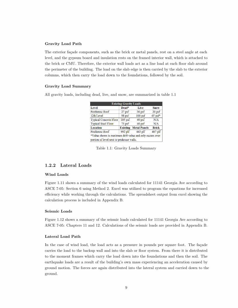
Gravity Load Path
The exterior façade components, such as the brick or metal panels, rest on a steel angle at eachlevel, and the gypsum board and insulation rests on the framed interior wall, which is attached tothe brick or CMU. Therefore, the exterior wall loads act as a line load at each floor slab aroundthe perimeter of the building. The load on the slab edge is then carried by the slab to the exteriorcolumns, which then carry the load down to the foundations, followed by the soil.
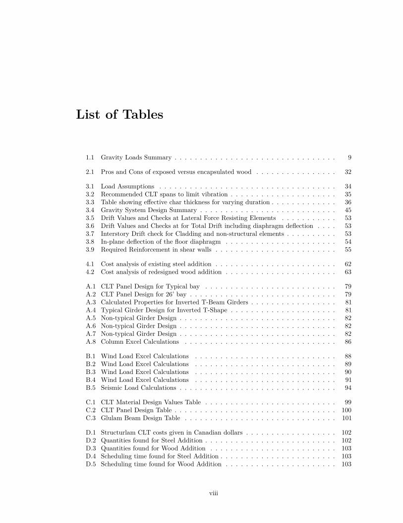
Gravity Load Summary
All gravity loads, including dead, live, and snow, are summarized in table 1.1
Table 1.1: Gravity Loads Summary
1.2.2 Lateral Loads
Wind Loads
Figure 1.11 shows a summary of the wind loads calculated for 11141 Georgia Ave according toASCE 7-05: Section 6 using Method 2. Excel was utilized to program the equations for increasede�ciency while working through the calculations. The spreadsheet output from excel showing thecalculation process is included in Appendix B.
Seismic Loads
Figure 1.12 shows a summary of the seismic loads calculated for 11141 Georgia Ave according toASCE 7-05: Chapters 11 and 12. Calculations of the seismic loads are provided in Appendix B.
Lateral Load Path
In the case of wind load, the load acts as a pressure in pounds per square foot. The façadecarries the load to the backup wall and into the slab or floor system. From there it is distributedto the moment frames which carry the load down into the foundations and then the soil. Theearthquake loads are a result of the building’s own mass experiencing an acceleration caused byground motion. The forces are again distributed into the lateral system and carried down to theground.
9
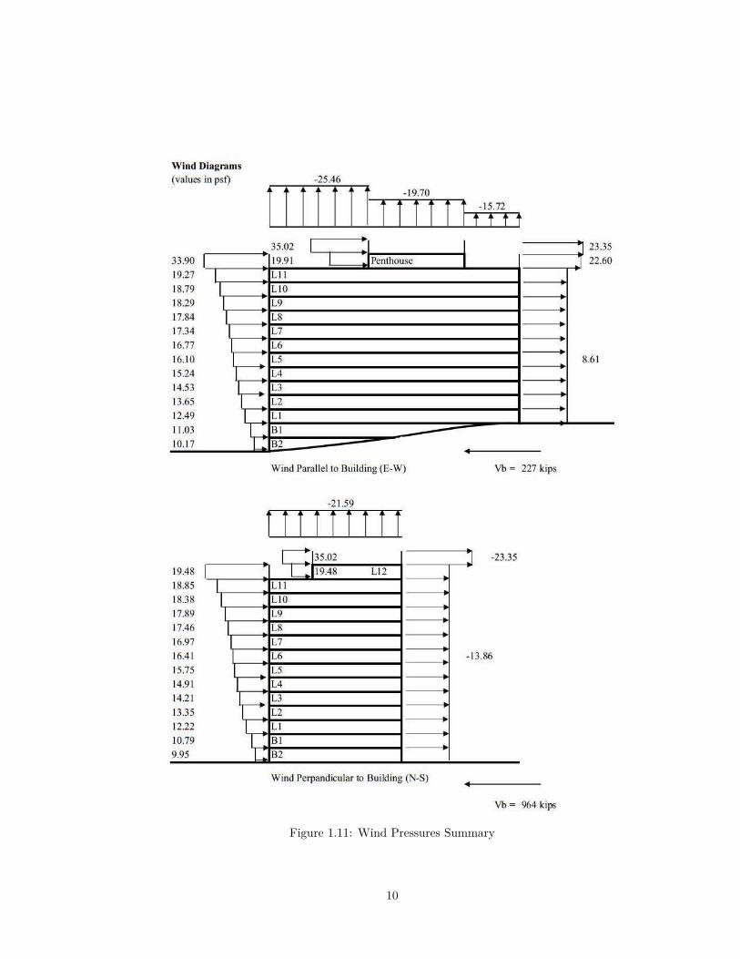
Figure 1.11: Wind Pressures Summary
10

Figure 1.12: Summary of Seismic forces on building
1.3 Thesis Problem StatementThe newly completed seven story addition to 11141 Georgia Avenue is currently a steel framedsystem built over a 1960’s concrete building. One of the benefits of the original design choiceto retrofit an existing building for new use is that it is a much more a�ordable and sustainablealternative than tearing down the building and starting from new. Although building retrofitis not always a feasible option, in this case, the reuse was a good design alternative for 11141Georgia Ave. Keeping the old building sacrificed some design freedom, but it also provided asustainable design alternative while reducing construction costs and schedule time. Sustainabilityis an important factor moving forward in modern building practices, and because of this theproposed thesis work will maintain the original intent by looking at a sustainable light-weightframed addition alternative which also has the potential to be cost and schedule competitive.
To accomplish these goals, the work completed will include a study and analysis of anengineered wood structure as an alternative framing system redesign for the addition. Despite notcurrently meeting requirements of the International Building Code, there are several significantbenefits to using wood; it is a sustainable and renewable material, it provides a lightweightalternative for the construction of a multi-story addition to an existing building, and it has the
11

potential to be built on a faster schedule resulting in a reduction in schedule-related costs. Thisthesis will acknowledge the current code limitations on wood construction, however it will alsostudy the feasibility of using wood as the primary structural material for the addition as well aswhether or not it could plausibly meet the goals of the code.
1.3.1 Justification for Design Approach
Currently, heavy timber construction for a residential occupancy is limited to four stories in theUS, and therefore the final wood re-design of 11141 Georgia Ave’s addition will not be immediatelyapplicable with regard to current codes. The current code limitations on heavy timber constructionare founded on relative overall building fire-resistance and the concept of limiting a building’ssize and egress lengths based on the resistance of combustibility of the main structural material.However, there is research which has been carried out and which is ongoing that indicates thatproperly detailed and designed wood construction can meet fire-rating standards and life safetygoals equal to steel and concrete construction for taller buildings than what is currently allowedby adopted codes in the US. Furthermore, other countries such as Canada and England havesuccessfully built heavy timber buildings as tall as six and upwards of nine stories.
As previously mentioned, wood construction has several benefits which would make it acompetitive alternative material not only for buildings taller than the four story limit, butspecifically for 11141 Georgia Ave. First, the redesign in wood will be a lightweight alternativeframing system. The existing steel addition floor structure is approximately 40 psf, while an initialestimate of wood framing weight is approximately 20 psf. Therefore, a heavy timber structure isan alternative that would put considerably less load and stress on the existing structure.
Wood buildings also show the potential to be built on quicker schedules. Since the structuralelements in a heavy timber building are all prefabricated, the structure can be built very quickly,similarly to the schedule of a pre-cast concrete building. Therefore, a wood addition may be builtmore quickly than the current steel design, allowing a reduction in overall schedule and generalconditions costs, as well as allowing the owner’s use of the building earlier.
Finally, wood shows great potential to be a sustainable construction alternative. Certifiedforests in the US are using more sustainable forestry methods and are working to improve uponthose methods. With the development of engineered glulam wood products, smaller trees canbe used in constructing large structural members rather than cutting down old growth forests.While steel and concrete are produced from non-renewable resources, wood is the only renewablebuilding material. Wood used in construction also has the ability to sequester carbon, e�ectivelyremoving it from the atmosphere for the lifetime of the building and potentially longer dependinghow the wood is used at the end of the building’s life. The study of a wood framing alternatewill include a review of the sustainability benefits of wood construction and will discuss how awood redesign of 11141 Georgia Ave’s addition is a sustainable alternative design for the building.Because of the increasing need to reduce emissions and explore options for production practiceswhich can be sustained moving forward, it is worthwhile to explore a wood design alternative inthe context of a real building project.
12

1.3.2 Proposed Solution
The proposed new wood-framed building will include a design similar to the existing steel-framedaddition. The 20�x20�bay size will be kept since a smaller bay will be beneficial for span whendesigning a wood framing system. Glulam structural elements will be used to achieve a heavytimber design, where the minimum beam or girder size and floor thickness for heavy timber is6" wide by 10" deep and 4" thick respectively. Minimum column size for heavy timber is 8"by 8". The layout used will include glulam girders and an engineered structural panel productwhich spans between girders. Initial strength calculations predict that girders may be 16" deepor greater, and the largest columns will be about 15" square, noting that the final sizes mustmatch available glulam sizes. The work for this thesis will include design of the primary structuralelements for strength, deflection, and expected fire loadings.
A wood framed building will also require a di�erent lateral system than the current steelmoment frame system. Therefore, the elevator core shear walls, which currently extend only untilthe top of the original concrete building, will be carried through to the top floor. The existingCMU shear walls will be kept as they are currently. There will be CMU shear walls around thestairwells for improved fire and smoke safety in the egress route. The design work and researchwill look into the feasibility of wood shear walls elsewhere. A benefit of continuing the shear wallsup in wood wherever possible is that it will add significantly less weight than continuing them inCMU from the concrete portion of the building, thus reducing the increased loads and foundationsize due to the change in the lateral system for the addition.
1.3.3 Solution Method
Structural Depth
The design of the wood floor system for gravity loads will be based on design values from theCLT Handbook and the Engineered Wood Association design guides, as well as information fromAE 401: Design of Steel and Wood Structures, BE 462: Design of Wood Structures, and anyother structural wood design resources. The CMU shear wall design option will be based onthe Masonry Building Code. The wood shear wall design alternative will use information fromexisting research on the topic as well as available design guides. Modeling of the structure willbe completed in ETABS modeling software. The research methods for this thesis work will alsoinclude seeking the advice of professors as well as professionals who are currently researching theuse of wood in tall buildings and those designing and implementing tall wood buildings.
Breadth Topics
Both breadth topic selections are a result of the selection of wood as a framing alternate and thee�ects of that decision on cost, schedule, and mechanical equipment. The breadth topics includea construction management and mechanical breadth.
13

Construction Management
In the construction management breadth, cost and schedule analysis will both be completed forthe existing and new addition. The focus of the cost analysis will be specifically on the existingand new additions themselves, but will take into account any significant changes to foundations,renovations, and general conditions costs due to scheduling. The schedule analysis will determinescheduling di�erences between the designs and identify any significant changes. The goal of thecost and schedule analysis in this breadth is to determine approximately if the wood designalternative is feasibly and economically competitive with its equivalent mid-rise steel addition inthe case of 11141 Georgia Avenue.
Mechanical
Since no concealed spaces are allowed in heavy timber construction, the ductwork, wiring, andother mechanical systems normally hidden above a drop ceiling will be exposed. This is animportant di�erence between the proposed wood redesign and the existing steel structure withdrop ceilings. Therefore, it is important for the mechanical equipment to be arranged aestheticallysuch that the apartments are just as appealing as in typical competing apartment buildings. Themechanical breadth will determine the changes that need to be made for aesthetic purposes andwill look in detail at one instance of an equipment change in a typical apartment.
14

2|Heavy Timber Construction
2.1 IntroductionHeavy timber is a construction type that uses engineered wood products as the main structuralelements of a structure. Heavy timber takes advantage of relatively recent innovations to createlarger structural elements out of smaller lumber sizes. Currently, US building codes limit woodconstruction to about four stories due to the combustible nature of wood. However, timberis beginning to be considered over steel or concrete construction for its sustainability benefits,and potentially quicker schedule time and lower costs. Therefore, research is currently beingconducted, especially in Canada and Europe to develop heavy timber as a construction alternativefor taller buildings with equivalent fire safety measures and details. The following chapter providesbackground information on the use heavy timber in taller buildings, including a summary ofcurrent research and research that will still be required before taller timber buildings could beseriously considered by code writing bodies.
2.2 Heavy Timber DefinedThere are currently two main types of wood construction; heavy timber and light frame con-struction, which are compared in figure 2.1. Light frame construction involves the use of smallerdimension lumber such as 2◊4, 2◊6, etc. to build up floor and wall framing systems, while heavytimber consists of large wood elements, such that floor decking is at least 3" thick, beams are6"◊10" or greater, and columns are at least 8"◊8". This thesis focuses on engineered woodproducts since it is more economical and sustainable to create larger structural elements fromsmaller-cut trees rather than trying to find large pieces or sawn lumber or damaging old growthforests. (Green and Karsh, 2012)
Within the engineering wood products which make up heavy timber elements, there are threemain types; cross laminated timber (CLT), glulam, and laminated veneer lumber (LVL). CLTincludes several layers of dimensional lumber, with the layers perpendicular to each other andstructurally glued together, as shown in figure 2.2 (a). Glulam is similar to CLT in that layers ofdimensional lumber are glued together. However, the layers in glulam are all parallel to each otheras shown in figure 2.2 (b). (FPInnovations and Council, 2013) Finally, LVL is made from peeled
15

(a) CLT Building. Source: woodwindow-stoday.blogspot.com
(b) Light-framed home. Source: arupconnect.com
Figure 2.1: Heavy Timber versus Light Frame Wood Buildings Under Construction
veneer layers from a log which are then structurally glued together with the grains perpendicularfrom layer to layer. (Green and Karsh, 2012) CLT will be the structural product used in thisthesis for the floor system because it is available in a panel product with a su�ciently widedimension, has better dimensional stability due to the nature of cross lamination, and is moresuitable for connection design than if glulam were used to create a panel product. Glulam will beused for girders and columns because of its availability for this purpose and its strength.
(a) Cross Laminated Timber Panel. Source: archi-expo.com
(b) Glulam Beams. Source: tim-berfirst.wordpress.com
Figure 2.2: Di�erent Types of Engineered Wood Products
2.2.1 Benefits of Heavy Timber
Heavy Timber is not common for use in buildings taller than about six stories, but a variety ofdesign firms, other countries such as England and Canada, research institutions, and manufacturersare increasingly interested in heavy timber because of its benefits. An engineered wood productmay be chosen alternatively to another material for a number of reasons; it is a sustainableand renewable construction material, it can be cost and schedule competitive, elements can bepre-fabricated, it is a lightweight material which reduces required foundation sizes, and it canprovide interesting design freedom.
16
Many of these benefits will be further studied in this thesis. The potential sustainabilityfeatures of using wood will be covered in this chapter. The redesigned CLT addition will beanalyzed for cost and schedule, and it will be compared to the existing addition to determine thee�ects of the wood system on cost and schedule for 11141 Georgia Ave specifically.
2.2.2 Challenges of Heavy Timber
Despite the benefits of using engineered wood products, there are several challenges to its use,especially in taller buildings. Challenges include fire-safety, public perception, code limitations,constructability knowledge, and several more.
Of these challenges, fire-safety and code limitations will be specifically addressed in this thesis.The addition redesign will be studied for its limitations with regards to the code, however itwill also attempt to address the goals of the International Building Code. Furthermore, existingresearch on the fire-safety of taller heavy timber buildings will be reviewed.
2.3 Environmental ImpactOne of the major reasons heavy timber is being explored as an alternate material for tallerbuildings is that it is a sustainable option. Although it would never completely replace steel orconcrete, wood has a lower carbon footprint and is less energy intensive to produce than bothsteel and concrete. Therefore, it is worth exploring the feasibility of wood in taller buildings as apotential sustainable alternative for a greater variety of buildings.
2.3.1 E�ects on Climate Change
Today, about 50 percent of the world population lives in cities, and it is expected that evenhigher percentages of the population will live in cities in the future (Green and Karsh, 2012).Furthermore, people spend most of their time in buildings. Because of this, it should be no surprisethat the construction and use of buildings accounts for a large portion of energy consumptionand greenhouse gas emission. Figure 2.3 shows that construction, electricity, and heating makeup almost 40 percent of energy consumption. Therefore, any improvements in the sustainabilityof the construction industry will have a significant e�ect.
There are a two main approaches to improving sustainability and preventing climate change;reduce greenhouse emissions, or store excess greenhouse gasses. Building with wood contributesto both of these approaches. The forests grown to produce wood become carbon sinks, and thecarbon stored in a tree will continue to be stored as it is used in a building. The manufacturingprocess of engineered wood products is also much less energy intensive than steel or concrete.Most importantly, while steel and concrete are produced from non-renewable resources, wood is arenewable resource. As long as forests are well managed and harvested sustainably, new woodmaterial can continue to grow indefinitely (Green and Karsh, 2012). In the US, both sustainableforestry and clearcutting are practiced, but the building industry generally uses FSC-certifiedproducts, which must meet requirements for sustainable forestry practices. (Edward Allen, 2009)
17

Figure 2.3: Percentage of energy consumption by sector. Source: e-education.psu.edu
The production, use, and growth of wood is ultimately a sustainable cycle rather than a one-waystreet, as shown in figure 2.4. This is not to say that there are not any e�ects on habitats andforests, but when done correctly, the harvested areas can recover quickly such that the overalllong term habitat is not negatively e�ected.
Figure 2.4: Production and Growth Cycle of Wood. Source: machielsbuildingsolutions.be
2.3.2 Life Cycle Analysis
When looking at the environmental e�ects of a buildings, the entire life of the building must betaken into account, including the production of its materials, its construction, the lifetime and
18

durability of the building, and finally the demolition and disposal or reuse of its materials.
Figure 2.5: Environmental Impact Comparison Between Wood and Other Construction Materials.Source: naturallywood.com
A life cycle analysis of a heavy timber building will include wood growth and carbon storage,energy consumption during the harvesting process, shipping and manufacturing, delivery tosite, construction, building lifespan, and end of life use of wood material. Whether the wood isreclaimed and reused, sent to a landfill, or used as fuel will significantly a�ect the net greenhousegas balances of the full life cycle of the building. (Börjesson and Gustavsson, 2000)
A criticism of the sustainable nature of heavy timber is that the carbon it sequesters will onlydelay it’s e�ect on carbon emissions as the sequestered carbon could potentially be released backinto the atmosphere at the end of a building’s life if the material is burned or sent to a landfill.This is an important point, and thus an e�ort should be made to design CLT structures such thatthe material may be reclaimed and reused at the end the building life. Fortunately, methods toaccomplish this are being developed to achieve such a goal. The only case in which the net e�ectis a positive emission of greenhouse gasses at the end of the life span is when the lumber goes toa landfill and a large portion is decomposed (Börjesson and Gustavsson, 2000).
At the very least, the delay of carbon dioxide release will buy upward of a 100 years oftime to make improvements to sustainability in the construction industry and other sectors,and the energy used during manufacturing is still lower than steel or concrete. Ultimately, lifecycle analysis of wood structures determines that the net e�ect on greenhouse gasses over thelife of a wood building will generally result in a reduction in emissions compared to steel andconcrete construction. (Gustavsson and Sathre, 2006) In the residential sector, it is estimatedthat wood frame homes versus steel or concrete alternatives cause 20-50 percent less emissionsduring construction (Upton et al., 2008) Therefore, the use of heavy timber in taller buildingsshould not be dismissed as it has clear potential to be a sustainable alternative constructionmaterial in a greater variety of cases.
19

2.4 Fire-SafetyFire-safety is a key consideration in modern building construction, in which the four maingoals of fire-safety include protection of life, protection of building, protection of contents, andcontinuity of operation, with life safety ranking as the most important fire performance goal(Walter T. Grondzik, 2010). Heavy timber buildings are constructed out of wood, which is acombustible material, and therefore these buildings must be designed di�erently from steel andconcrete buildings to achieve the same level of fire safety.
2.4.1 Heavy Timber Fire Resistance
In any building constructed, there will be both passive and active methods of fire-protection.Active methods involved the use of systems such as sprinklers and smoke detectors. This servesas the first line defense in most buildings. Passive methods serve as the last resort as far askeeping a building fire under control, and they take advantage of the inherent fire-resistanceproperties of the materials used in construction. This section will provide an overview of thepassive fire-protection in heavy timber.
Passive fire-protection is dependent on the building materials themselves, and therefore willvary between construction material types. In steel construction, additional fire-resistant materialsmust be added to protect the steel since steel loses strength quickly in high temperatures. Incontrast, concrete itself is resistant to fire and therefore provides its own fire protection. Wood issomewhat similar to steel in that it must be protected from fire. However, heavy timber bearssimilarity to concrete as its fire protection is inherent in the material itself. This behavior is shownin figure 2.6. When wood burns, it forms a char layer which then acts as an insulating layer forthe rest of the wood. The next layer inward is a heated layer which doesn’t burn when protectedby the char, but which undergoes thermal decomposition. This second layer is called the pyrolysiszone. The innermost layer remains protected with all or most of its structural capacity. Thewood elements in light frame construction are too small to retain an unheated wood inner layer,but engineered heavy timber products are large enough to retain a protected inner structuralsection. (Gerard et al., 2013)
Some of the main approaches to making taller heavy timber buildings safer in a fire includedesigning a sacrificial layer of wood to protect the structural wood required for a reduced loadcondition during a fire, redundant sprinkler and alarm systems, gypsum board encapsulation,compartmentalization design to prevent spread of smoke and fire, and use of non-combustiblematerial for egress stairwells.
When designing heavy timber structural elements, the known char rate of wood can be used todesign in a sacrificial layer such that the structural core of normal wood can continue to supportthe predicted loads during a fire. Initial research has shown that this method can be used toobtain a two-hour or greater fire-rating. Furthermore, the thickness of a floor slab for examplewill still most likely be governed by other existing strength or deflection requirements, such thatthe design of a sacrificial layer during reduced fire load conditions would tend to add insignificantadditional thickness for the final design. (Green and Karsh, 2012)
20

Figure 2.6: Layers in Burning CLT Panel. Source: FPRF
2.4.2 Code With Respect to Fire Safety
The International Building Code determines maximum allowable heights and areas based onbuilding occupancy type and construction type. There are five construction types, which generallydefine how fire-resistant a building must be in order to fall within that category. Heavy timberand engineered wood are in category IV, which currently restricts the maximum number of storiesfor any heavy timber building to six stories. For residential occupancies, the number of stories islimited to four. The limit on the number of stories to achieve these goals varies from country tocountry, as shown in figure 2.7. Category IV includes heavy timber structures, with the importantdefining characteristic being that the main structural materials are combustible.
Figure 2.7: Review of Max Code story limit in various countries. Source: Fire Protection ResearchFoundation (Gerard et al., 2013)
21

Fire Safety Goals
The International Building Code limits the number of stories in a building with the idea thatfire-safety is a�ected by the type of construction. The intent of the code is to limit area, height,and number of stories as a method to improve the level of a building’s fire-safety with increasingbuilding structure combustibility. However, the fire safety goals which are the intent behind thecode choices, are important considerations. Proponents of taller wood buildings argue that aslong as the goals of the code with regard to fire-safety are met, then buildings should be allowedto be constructed taller. As mentioned before, the main fire safety goals include protection of life,protection of building, protection of contents, and continuity of operation. (Walter T. Grondzik,2010)
Life safety is regarded as the most important of goals, and thus the code includes a lotof provisions aimed at protecting the occupants while they are leaving the building during anemergency. Some of the unique challenges a heavy timber building poses towards meeting thisgoal include smoke control due to the combustible nature of the structure itself, fire performanceof egress routes which may or may not include wood shear walls around a core, and the typicalenclosed spaces found in steel and concrete buildings which would allow the quick and quietspread of fire and smoke. Life safety was the primary goal under consideration when making fireperformance-related design decisions throughout this thesis.
Protection of the building is another goal which has unique challenges for a heavy timberbuilding as opposed to steel and concrete buildings. If the structure is ignited, it will combust,unlike concrete which is fire-proof, and steel, which just loses strength. However, since heavytimber is di�cult to ignite due to its mass, small fires which can be suppressed by sprinklersystems will not pose significant damage threats. Once a fire becomes large enough in a buildingthat several structural members require complete replacement, it is likely that life safety andpreventing a progressive collapse will become the main goal. Most of the time, the mechanicaland sprinkler systems will prevent large fires, thus limiting damage to a level which can be easilyrepaired.
The goal of protecting contents will most likely be similar in a heavy timber building as inother buildings. The method to protect the objects within a building will primarily be throughthe sprinkler systems. As long as the sprinklers are functioning properly, they can be extremelye�ective at suppressing, and even putting out, a fire just as it is starting. The final goal continuityof operation, and as with the goal of protecting the building contents, the sprinkler system wille�ectively suppress a fire, thus limiting its e�ect to a single room. This system, along with a firealarm system, will typically prevent serious fires from occurring. Thus, although a heavy timberbuilding behaves di�erently than steel or concrete, the fire protection methods in place to meetthe goal of operational continuity are the same.
2.4.3 Topics requiring further study and research
Although heavy timber is fairly well understood with regards to how it burns and behaves ina fire, there are other details which pose fire-safety challenges and which require further study
22

before taller wood buildings can be considered and eventually accepted by the code. Some of themain areas that require further research include CLT delamination and char fall-o�, penetrationsfor services, timber façades, and protection of egress routes. (Gerard et al., 2013)
CLT Delamination and Char Fall-O�
CLT delamination and char fall-o� occurs uniquely in CLT engineered wood products. Delam-ination may occur once the char layer reaches an interface between layers, and the car couldfall o� in pieces, causing the panel to burn more quickly, and contribute more burning load toa compartment fire. Figure 2.8 shows a piece of a lamination falling during fire testing. Thisbehavior a�ects the overall fire-rating of a floor or wall assembly and is being studied to determineconditions under which char fall-o� may occur. (Gerard et al., 2013)
Figure 2.8: Falling delaminated lamination during CLT fire testing. (Frangi and Jobstl, 2009)
Service Penetrations
Openings for mechanical, electrical, and other service equipment must be just as fire-resistant asthe floor or wall assembly to prevent the spread of fire to other spaces. This is an approach tokeeping the fire relatively contained within a single compartment of the building for as long aspossible. In most cases, a fire-rated caulk or other firestop system may be used to fire-proof thepenetrations for services. However, in heavy timber buildings, since the wood panel material ina floor or wall is combustible, the wood surrounding the opening and its seal will char, therebycompromising the area around the openings and potentially allowing smoke through the charredareas. A potential solution is to extend the firestop system material into the panel to protect anextended circumference of the opening. This method is promising, however it poses constructabilitychallenges and still requires further fire-testing and research.
A final challenge for openings is to educate building owners about fire concerns related tocreating new openings to move or add services in the future. It is possible that during the lifetimeof a building, an owner may, for example, move outlet receptacles and create a new opening whichis not properly fire-protected. Not only is the education of the initial owner important, but the
23
transfer of information to educate any future building owners is important as well. (Gerard et al.,2013)
Façades or Exterior Walls
If the building is completely constructed out of timber, including timber exterior walls and/orfaçades, then fire spread via the exterior is a concern. If the façade catches fire, then the flamescan spread to upper stories through the exterior of the building. Some options include usingfire-retardants, however the use of timber in façades is fairly new and not well understood.Therefore, the redesign of 11141 Georgia Ave will not include a timber façade, but will keep theoriginal brick façade. (Gerard et al., 2013)
Protection of Egress Routes
Finally, one of the main goals of fire-safety is to provide occupants with adequate time and anavailable egress route to exit the building safely. The stairwells in a multi-story building arecritical for egress, and therefore should have higher standards of protection. This is related to thefour story limit for heavy timbers, since four stories is the maximum height at which a ladderrescue is feasible. Timber panel shear walls are potentially structurally feasible, however, whenthose shear walls exist in a stairwell core, smoke production is a concern for egress. Since wood iscombustible, as soon as it is exposed to fire within a stair well, it will burn and produce smoke.In the redesign for Georgia Ave, wood shear walls will be use where possible since this is theprevailing practice for heavy timber residential construction in the US. However, since the timberportion of the building is well beyond the reach of ladder rescue, a masonry or concrete shear wallwill be used around the stairwells to increase the building’s egress safety. (Gerard et al., 2013)
2.5 Additional ConsiderationsThere are other considerations which come with choosing heavy timber and engineered productsfor taller buildings. This includes vibration performance, sound insulation, building envelopedetailing, keeping wood panels relatively well protected from extended water exposure duringconstruction, and fire-safety during construction. (FPInnovations and Council, 2013) Theseconsideration will be discussed briefly here, but most will not be fully explored in the redesignwork of the 11141 Georgia Ave addition.
2.5.1 Vibration Performance
Vibration performance should be considered in CLT buildings because they tend to have a criticaldamping ratio less than typical lightweight wood joist floors. Therefore, it is more di�cult tocontrol vibrations in CLT floors. Wood in general is more susceptible to vibrations than othermaterials due to its lightweight nature. However, there is a design method presented in the CLTHandbook which uses a CLT floor’s mass to control the vibration response. In a residentialoccupancy such as 11141 Georiga Ave, vibration performance is not as critical because people
24

tend not to do work that requires them to focus on a computer for awhile such as they would atwork in an o�ce.
2.5.2 Sound Insulation
Sound insulation is an important factor in building design, especially for residential occupancies asin the case of 11141 Georiga Ave. Poor sound insulation can result in unpleasant living conditionsand distractions to occupants. The IBC requires a minimum Sound Transmission Class (STC)of 50 for walls and floors and an Impact Insulation Class (IIC) of 50 for Floors. For a 5-layerCLT panel, the STC is 39, which could be easily improved to meet code by adding drywall orother methods. The IIC of a 5-layer panel is 24, which is fairly poor. Providing a floor systemwhich meets IIC requirements will likely require some type of floor topping. (FPInnovations andCouncil, 2013)
Ultimately, wood floors and walls create the challenge of meeting acoustic-related coderequirements. Since the wood products themselves don’t provide the required STC and IIC values,acoustic-insulating materials must be added to meet code. Therefore, if a thick floor topping isrequired, the floor to ceiling heights will be a�ected, and possibly the height of the structure aswell, if the floor to floor height needs to be increased. Figure 2.9 shows a potential wall assemblywhich meets code, while figure 2.10 shows a potential floor assembly which meets code.
Figure 2.9: Acoustic Wall Assembly. Source: CLT Handbook.
The floor assembly requires an additional 4" topping below the floor covering. This issignificantly thick as the original floor finish topping in the addition was only about an inch thick,and will be taken into account in determining the final floor to ceiling heights resulting from thegravity system redesign.
25

Figure 2.10: Acoustic Floor Assembly. Source: CLT Handbook.
2.5.3 Envelope Design
All building envelopes must keep the structure and interior of a building dry. Therefore, therequirements for wood are not much di�erent from steel or concrete despite public perception.Although wood rots when exposed to moisture for lengths of time, concrete and steel are degradedby water as well. There are however, some envelope considers unique to wood design. Since woodis organic, a main issue is termites, as they can eat out the inside of a wooden element withoutleaving many exterior signs of damage. A method to protect a building from termites is to build aconcrete podium as a base above ground level. Since the 11141 Georgia Ave addition is built abovea multi-story addition, termites will not be a problem for the redesigned wood addition. A benefitof using wood as part of the exterior wall is that it has low thermal conductivity, and thereforeprovides some amount of insulation value for an enclosure, adding to the energy e�ciency of thebuilding. (FPInnovations and Council, 2013)
2.5.4 Construction Challenges
All materials have special considerations during a building’s construction phase. This is becausethe building is unfinished and does not have all of the protection or support systems that completeits design. Two challenges unique to heavy timber construction, or wood construction in general,include protection from moisture and fire.
Since CLT and other wood products do not do well when exposed to moisture for an extendedtime, it is important to protect the wood from moisture during construction before the enclosurehas been built. A potential method of protection is to erect a temporary tarping system, whichwould most likely be attached to the sca�olding around and over the building (Figure 2.11). Thiswill serve as a temporary envelope to protect the wood during construction. (FPInnovations andCouncil, 2013)
A review of heavy timber fire incidents from the Fire Protection Research Foundation indicatesthat many of the most serious fires in heavy timber buildings occurred during construction or
26

Figure 2.11: Moisture Protection of CLT During Construction. Source: CLT Handbook
renovations. While the building is under construction, it does not yet have sprinklers, alarmsystems, protective gypsum board, or any of the other methods used for fire protection. Therefore,the building is at more risk to burn down completely should a portion be ignited. Additionally,the tools used during construction and renovation produce a lot of heat, and therefore care mustbe taken to prevent ignition caused by construction activity. Finally, if there are other buildingsclose by, a fire during construction could put surrounding structures at risk as well. In this case,additional precautions must be taken to prevent fire during construction. (Gerard et al., 2013)
2.6 Literature ReviewThe following section reviews current literature and research towards the feasibility of taller woodconstruction as a sustainable, fire-safe, and cost competitive structural system alternative.
CLT Handbook (US Edition)
Cross laminated timber is a product which is being used for taller wood construction in countriessuch as Canada and England. Within the last five years, a few CLT manufacturers have started upin the US, and as a result, a CLT Handbook has been made available to aid with the design of CLTbuildings. The Handbook was published in 2013 through the combined e�orts of FPInnovationsand the Binational Softwood Lumber Council.
The handbook includes information on design for gravity and lateral loads, connections, vibra-tion and sound insulation performance, construction management considerations, fire-performance,and more. Material design values provided in the CLT Handbook were used in the structuralsystem redesign. (FPInnovations and Council, 2013)
27

Timber Tower Research Project
Skidmore, Owings, and Merrill completed a conceptual project in May 2013 in which theydeveloped a structural system for taller timber buildings and applied the system to a prototypebuilding design based on an existing concrete building. The goal of the project was to create abuilding that was as sustainable as possible while also being cost competitive with other typesof modern construction. The scope of the project includes the structural design, architecturaldesign, building services design, an embodied carbon analysis, recommendations, and more.
The benchmark building chosen for comparison was the Dewitt-Chestnut Apartment buildinglocated in Chicago. The structure is a concrete flat plate system with gravity columns anda tube frame around the perimeter for the lateral system. The structural system used was a"concrete jointed timber frame." This system includes the use of mass timber products for themain elements such as floors, columns, and shear walls. The connections are made through theuse of reinforcement and concrete joints. There are also perimeter concrete beams, with the floorsspanning from the core to the perimeter beams. Some structural issues came up during the designprocess. Since the wood prototype is much lighter than the concrete benchmark, net uplift due towind loading became an issue. Furthermore, the lateral system required more lateral elements inthe prototype to achieve the same sti�ness as in the benchmark. SOM designed the prototype toaddress these issues.
The design project also looked at design for fire and determined that the most practicalapproach would be to follow a performance based design method since taller timber buildingsof this construction type do not quite fit within the framework of the code. SOM decided thatthe project should meet the goals of the code, which include protecting the safety of occupantsand fire fighters during a fire as well as preventing a progressive collapse or major failure of thestructure. Many principles for fire design were created, including the concept of using fewer largerstructural elements in the design rather than multiple smaller elements. For example, a thickerfloor without ribs would be preferred over a thin floor with beams. Ultimately, SOM recommendscompleting a full building fire performance analysis for final design rather than just looking atassemblies fire ratings alone. (SOM, 2013)
The Case for Tall Wood Buildings
A prototype building design approximately 70 feet square was created in order to investigatethe feasibility of wood in taller buildings. Structurally, the prototype building used a "strongcolumn/weak beam approach," where the shear walls serve as the strong column and steel W-shapes served as the weak beam, adding ductility to the structure. In buildings 12 stories orless, lateral forces could be adequately resisted by a wood shear wall core alone. As the buildinggets taller, additional shear walls and then perimeter moment frames are required when a woodlateral system is still used. Therefore, as a wood building gets taller and keeps wood as the lateralsystem, the overall freedom of architectural design may become greatly reduced.
The report also looked at fire performance and determined that for the prototype building,the char method alone could be used as the passive fire protection. In this case, the design was
28

controlled by deflections and vibration performance rather than by fire performance. The reportacknowledges however that most early CLT buildings will use the encapsulation method untilmore research is done. Other topics regarding the feasibility of taller wood buildings were explored,and the report ended with several recommended studies which would further the research. (Greenand Karsh, 2012)
Fire Safety Challenges of Tall Wood Buildings
In 2013, the Fire Protection Research Foundation compiled current knowledge on the topic oftall wood building fire safety and identified gaps in knowledge which require further research andstudy.
A review of major fire incidents revealed that the worst fires in wood buildings occurred in afew typical cases. The highest risk generally appeared in light frame wood buildings. There is ahigher risk of fire during construction prior to the installation of fire protection systems. Theconstruction phase also tends to pose a risk due to the tools and equipment used in the process.Also, fires occurred often in buildings with concealed spaces, which allowed routes for rapid fireand smoke spread throughout a building. In heavy timber, large fires have been less likely tohappen because of the inherent fire resistance of the large sizes and surface area. Ultimately,lessons learned previously, and knowledge of fire behavior can be implemented to protect tallerwood buildings against fire.
The study identified some gaps in knowledge of taller wood buildings related to; e�ects ofstructural loading on fire performance, full system fire testing, CLT delamination and char fall-o�,pipe and service penetrations, fire spread through timber façades, and protection of egress routes.(Gerard et al., 2013)
Greenhouse Gas Balances in Building Construction
Pal Borjesson and Leif Gustavsson co-published a paper in 1999 which compared green house gasemissions of multi-story concrete and wood buildings in both a life cycle analysis and a land-useanalysis. The study found that the initial energy used to manufacture the building materialsis approximately 60-80 percent higher in a concrete building than a wood building. The netgreenhouse gas emissions (GHG) in a wood building were determined to vary greatly dependingon end of life use. If the wood is reused, then the net GHG emissions are negative. However, ifthe wood goes to a landfill, it will produce biogasses such as methane as it decomposes, thuscausing net positive GHG emissions. If those biogasses are used to replace fossil fuels, however,then the GHG emissions are negligible.
The concrete analysis in the paper considered the absorption of carbon back into the concreteover its lifetime through the carbonisation process. When this occurs, the net GHG of a multi-storyconcrete structure is approximately the same as when the wood at the end of the building lifedecomposes in a landfill. The paper came to the conclusion that the entire life cycle of a buildingplays an important role in the overall sustainability of a building. Wood is most beneficial at thebeginning of the cycle during the manufacturing process, but requires care at the end of life to
29

make sure it is disposed of or reused in a sustainable manner. (Börjesson and Gustavsson, 2000)
The Greenhouse Gas and Energy Impacts of Using Wood Instead ofAlternatives
In 2007, Brad Upton, Reid Miner, Mike Spinney, and Linda Heath published a paper on theGHG and energy impacts of using wood versus alternatives in US residential construction. Thestudy found that houses built using wood require about 15 percent less energy than concrete orsteel homes for non-heating and cooling energy requirements. When looking at a 100 year periodof time, the wood homes were found to perform even better, with a 20 to 50 percent decreasein emissions. The important di�erence is that steel and concrete materials required the use offossil fuels in the manufacturing process, which account for much higher greenhouse gas emissions.(Upton et al., 2008)
Developing Hybrid Timber Construction For Sustainable Tall Buildings
Carsten Hein wrote an article for the Council of Tall Buildings and Urban Habitat (CTBUH)Journal in 2014 about hybrid timber construction in sustainable tall buildings. The articlerecognizes that wood has great potential for use in taller buildings, and discusses its use incomposite system design. The article reviewed a proposed concept for a 20-story tower usinga timber-concrete-composite (TCC) floor system. An 8-story prototype using the TCC floorsystem was built and tested in 2011. The floor uses a concrete slab with glulam beams. Asound-absorbing floor was included in the project to test acoustical properties. The floor metacoustical requirements, but may not have been the most cost-e�ective solution.
Fire testing was carried out and the floor system achieved 90 minutes of fire resistance in atest by the PAVUS Test Institute in the Czech Republic. The building design also included aconcrete core for lateral stability and to provide a main fire egress route. A cost analysis wasperformed, and the project was about 105 to 110 percent the cost of a typical o�ce building. Theproject also determined the sustainability benefits of the building and found that the conceptreduced the building’s embodied carbon by about 50 percent. Ultimately, it was found that ahybrid timber building is feasible and can meet various performance requirements. (Hein, 2014)
2.7 Application to 11141 Georgia AveThe selection of heavy timber for the redesign of the 11141 Georgia Ave addition requires a varietyof considerations related to building outside the code. The code limits residential heavy timber to4 stories, but the addition is 7 stories and located on top of an existing concrete building. Thefire-safety goals behind that limitation will be considered in the redesign.
30

Structural
Factors which will primarily a�ect the structural redesign include increasing structural elementsizes for better performance during fire, the wall type surrounding stairwell egress routes, andfloor and wall system design for sound insulation.
The design of the floor gravity system elements, in addition to being designed for typical loadssuch as flexural, and deflections, and will be designed for fire conditions. As mentioned previously,a sacrificial layer can be designed such that the remaining protected wood is still able to carrythe required loads for the duration of occupant egress. Also, a topping may be required for soundinsulation, causing an increase in design loads as well as a�ect the floor to ceiling height. Thesewill both be considered in the addition redesign.
Construction Management
Any heavy timber building will have many e�ects on the construction management process. Theredesign work will primarily consider schedule and cost di�erences between the existing additionand the redesign. Several research studies have concluded that CLT construction can be cost andschedule competitive with other methods of construction. This thesis work will act as a feasibilitystudy and determine whether or not in the case of the Georgia Ave addition CLT construction iscost and schedule competitive with the existing addition.
Mechanical
Many of the more severe fires in heavy timber structures have occurred when concealed spacesexist. A fire can spread quickly and quietly through concealed spaces, bypassing the sprinklerand alarm systems that would have prevented damage in the event that the fire started in anoccupied space. Therefore, modern heavy timber buildings are not permitted to have concealedspaces, and the mechanical equipment will be exposed. The mechanical breadth will thereforeconsider the aesthetic placement and selection of mechanical equipment, will the goal to make theapartments aesthetically competitive with the original design.
Drywall Encapsulation
A significant design decision which a�ects many aspects of the redesign is weather to leave thewood exposed or to use the drywall encapsulation method. Based on the pros and cons in variouscategories shown in table 2.1, the drywall encapsulation method was chosen for this project. Thefactor given the most weight in the decision was fire-performance. Although it may be possibleto achieve equivalent fire safety standards with an exposed structure, it is more likely that thefirst tall wood buildings in the US will be required to have some level of drywall encapsulation tomeet stricture fire safety standards.
31

Table 2.1: Pros and Cons of leaving wood structure exposed versus using the drywall encapsulationmethod
2.8 ConclusionsThe concept of using heavy timber in taller structures is relatively new, and therefore there aremany potential benefits and challenges that are still being studied and explored. The decisionto use heavy timber for the redesign of the 11141 Georgia Ave addition has many implicationsfor the design work. Since the addition is three stories higher than the limit for heavy timber inresidential and built on top of a multi-story building, extra care must be taken to ensure that thestructure meets the goals of the code. Ultimately, the use of heavy timber significantly e�ects thestructural depth work as well as both the construction management and mechanical breadths.
32
3|Structural Redesign
3.1 IntroductionThe existing steel addition of 11141 Georgia Ave has been redesigned using engineered woodproducts. Both the gravity and lateral systems were redesigned, and the methods and results ofthe redesign are presented in this chapter.
3.2 Gravity SystemThe gravity system was designed using hand calculations. A typical bay layout uses a multi-plyCLT panel to span the full 20.75’ typical bay in the east-west direction. The panels are supportedby glulam girders which span along the width of the building similar to the building shownin Figure 3.1. The girders frame into glulam columns which follow the same layout as theexisting steel addition’s columns. The following sections describe the calculation process andassumptions used to design the gravity elements. Values and design procedures come from the 2015NDS (American Wood Council, 2015), the Glulam Specification (APA - The Engineered WoodAssociation, 2008), and the Glulam Column Guide (APA - The Engineered Wood Association,2009).
3.2.1 CLT Floor Panel Design
The floors were designed using a Cross Laminated Timber panel product, as described previouslyin chapter 2. Although the panels have two-way properties, the maximum deliverable panelwidth is shorter than the bay width. Therefore, it was assumed that each panel spans one-wayfrom girder to girder. Most panels span 20.75’, and therefore the typical panel will be keptthe same throughout a floor, including around stair and elevator cores, for uniform thickness.The only place where a di�erent design will be used is between grids 2 and 3 where the span isapproximately 26’. The floor panels were designed for strength, deflections, and fire performance,the processes for which are described in the following sections. Initial hand calculations and excelcalculation tables can be found in Appendix A for reference.
33

Figure 3.1: Image of Structural System Used with CLT. Source: City of Melbourne online site
Load Calculations and Assumptions
The CLT floor panel design was completed for three floor types; the typical level, level 12, andthe penthouse roof. The load assumptions for each level type are shown in table 3.1. The deadloads shown are based on including the self-weight of either a 5-ply or 7-ply CLT panel, and innon-typical cases, the dead load has been adjusted for other panel thicknesses as required. The12th level snow load shown is slightly below the maximum drift value because even in the bay inwhich drift occurs, the overall average drift in psf would be lower than that at the maximum.
Table 3.1: Load Assumptions
Design for Bending Strength
The CLT panels were designed for strength assuming a simply supported span. The maximummoment for a panel was found based on the applicable load cases for the given level using equation3.1 for a 1’ unit strip width of panel, treating it like a simply supported beam. Then, rearrangingequation 3.2 into equation 3.3, the calculated moment can be used to choose a panel size basedon the required section modulus.
M = wl2
8 (3.1)
34

Srequired
= M
Fb
(3.2)
M Æ Fb
◊ Srequired
(3.3)
The Fb
values used for design came from the US edition of the CLT Handbook (FPInnovationsand Council, 2013). A table showing values for F
b
and Fb
*Srequired
for various material gradesand panel thickness can be found in Appendix C. Anytime an allowable stress F
b
is used in thisand the following design sections, the following factors are assumed:
CM
= 1.0C
T
= 1.0C
i
= 1.0C
D
= 0.9 for dead load, 1.0 for live, 1.15 for snow, 1.25 for construction, 1.6 for windC
F
or CV
will be determined as required.
Deflection Check and Serviceability
Deflections were limited to l/360 for service live loads and l/240 for service dead plus live load.The following equation for a simply supported beam was used with a 1’ strip unit width of theCLT panel. The value for EI was found using a table from the CLT Handbook, which can befound in Appendix C. A factor of K
cr
= 2.0 was applied to dead load due to long term deflectionand creep of wood per the National Design Specification for Wood Construction.
� = 5wl4
384EI(3.4)
Additionally for serviceability, design for vibrations was checked. Table 3.2 provides recom-mended CLT spans to limit vibrations. The 12th level is considered an assembly space and has a7-ply panel which meets the recommended span limit. Although the 5-ply panels on other levelsdo not meet the limit of 18 feet, they only span 20 feet, which is close to the limit. Furthermore,the spaces on the levels with 5-ply panels are not expected to be as sensitive to vibrations as ano�ce environment for example. Therefore, the 20 foot span may be considered acceptable in thiscase.
Table 3.2: Table showing recommended spans for various CLT thicknesses to limit vibration.Source: CLT Handbook
To help improve vibration performance, single bay CLT spans will be used. In the CLThandbook, continuous spans are not recommended across units in multi-family because of flank
35

transmission. Furthermore, the additional sti�ness provided by continuous spans would limitdeflections, but it has not been shown to improve vibration performance since the mass is thesame. Therefore, the single span panels will help to isolate the apartments from other units, thusdecreasing the vibrations observed.
Fire Performance
The design for fire performance combines both the encapsulation and char methods. Althoughthe research being done by design firms and other associations show that it is possible to designcompletely exposed CLT structures for adequate fire performance, this redesign chose a moreconservative approach. The wood elements will be encapsulated in a layer of drywall to reduce thedepth of charring during two hours as well as increase the likeliness of US code o�cial acceptancesince the 1st tall wood buildings accepted will most likely have drywall encapsulated wood.
The drywall will be installed up against the CLT panel such that there are no concealed spaces.Each layer of drywall provides an additional 30 minutes of fire protection. Table 3.3 shows thetotal e�ective char in a CLT panel for varying periods of time. The portion of the panel withinthe e�ective char layer is assumed to no longer add any capacity to the section. The CLT paneldesign began with the assumption that a single layer of drywall protects the panel, and thereforethe e�ective char used for design will be taken after 90 minutes as 2.5", since the drywall providesthe initial 30 minutes.
Table 3.3: Table showing e�ective char thickness for varying duration. Source: CLT Handbook
The calculation was completed using the following methods. First, reduced loads were foundsince after two hours, it is assumed that many people will have left the building by then andlive loads will be much lower. It was also assumed that the 12th level would no longer be actingas an assembly space two hours into a serious fire, and so it was treated like a residence space.Furthermore, the structure itself and its contents will have burned away after two hours, andtherefore the dead load would be reduced. The controlling case used for fire performance designis dead plus live.
(D + L)reduced
= (0.75D) + (0.4L) (3.5)
M = (D + L)reduced
l2
8 (3.6)
36

Next, the residual panel thickness was found using the e�ective char depth. Since the e�ectivechar depth is 2.5 inches, and 2 plies of a panel are 2.75 inches, approximately 2 plies no longercontribute to strength. Therefore the e�ective residual structural panel thickness was taken to by2 plies less than the original thickness.
#pliesresidual
= #pliesoriginal
≠ 2 (3.7)
The Fb
Se�ective
used in this stage of the design will be that o� the residual panel thickness.Similar to strength design, the calculated moment must be check against this value.
Mfire
Æ (Fb
◊ Srequired
)resid.
(3.8)
Panel Connections
The CLT floor panels require a connection between panels in the direction of the span. Thisconnection detail allows the panels to act together better and prevent di�erential deflectionsfrom panel to panel due to variations in loading. Figure 3.2 shows 2 spline options to create thisconnection.
(a) Single Spline Connection. Source: CLTHandbook
(b) Double Spline Connection. Source: CLTHandbook
Figure 3.2: Spline connection options between panels
3.2.2 Glulam Girder Design
The CLT floor panels span into the girders, which were designed using a glulam engineered woodproduct. It should be noted that a fire-rating calculation exists for glulam, however, the codelimits the use of that calculation to one hour even if the equation gives higher values. However,the NDS provides values for char thickness, which will be used in the design. At 90 minutes, thereis an e�ective char thickness of 2.5".
The girders will be an inverted T-shape to provide a base for the floor panels to frame into.In the typical detail where brackets are provided, to support a girder framing into a rectangularbeam or a wall, the connection may be relatively large and bulky. In this design, since it isimportant for the drywall to fully encapsulate the wood tight to the surface, this design should
37

be avoided. Furthermore, a goal is to limit the depth of the structure, so it is not acceptable tosimply frame the panels on top of the girders. The inverted T connection detail will also provideprotection for steel fasteners since they will be buried in lumber, as shown in figure 3.3. Theconnection on the right in figure 3.3 is a proposed connection in which the T-girder flange provides4" of bearing for the CLT panels framing into each side. Self-tapping screws or another fastenertype can be used to connect the elements. Connection design is a topic within CLT buildingswhich requires more study depending on the requirements of the connection.
Figure 3.3: Connection options for rectangular girder versus inverted T
The girders have been designed for strength, deflections, and fire performance at each leveltype. Hand calculations for typical girders and excel calculations for both typical and non-typicalgirders are available in Appendix A.
Load Calculations and Assumptions
The load assumptions for the girder design are the same as they were for the CLT floor paneldesign. The only di�erence here is that the self-weight of the girder must be added to the deadload. based on an approximate initial guess of a 12◊20" girder, 50 plf was used for the girderself-weight in the design calculations. All final girders sizes weighed less than this, and thereforeit was a conservative design choice and does not need to be rechecked.
Design for Strength
The glulam girders were designed for strength assuming a simply supported span. The design forstrength is very similar to the CLT panel since the panel was designed per 1’ strip and treatedlike a beam. The maximum moment in a girder was found based on the applicable load cases forthe given level using equation 3.9. Then, a girder size can be chosen based on the required sectionmodulus and available typical sizes. The strength calculations used F
c
=2400 psi and E�= 1.8◊106
psi, as found in the Engineered Wood Association’s Glulam Design Guide for Douglas-Fir.
38

M = wl2
8 (3.9)
Srequired
= M
Fb
Cv(3.10)
Sactual
Æ Srequired
(3.11)
In addition, the girder design requires the use of a volume factor, CV
:
CV
= 12d
(1/10)
◊ 5.125b
(1/10)
◊ 21L
(1/10)
(3.12)
Since the girder is an inverted T-shape, the flanges contribute to the girder’s strength capacity.Originally, the calculations for strength did not include the flanges for simplicity, especially sincedeflections or fire performance usually controlled. However, there were significant advantages totaking the time to calculate the section properties for the T-shapes and this ultimately helpedthe e�ciency of the design. The F
b
values used for design came from the APA Engineered WoodAssociation Glulam Design Guide.
Deflection Check
As in the strength check section, the deflection check here is very similar to the check for theCLT panel. Deflections were limited to l/360 for service live loads and l/240 for service dead pluslive load. The following equation for a simply supported beam was used to check a girder fordeflection. The value for EI was found using a table from The Engineered Wood AssociationGlulam Design Guide, which can be found in Appendix C. A factor of K
cr
= 1.5 was applied todead load due to long term deflection and creep of wood per the National Design Specification forWood Construction.
� = 5wl4
384EI(3.13)
Fire Performance
The design for fire performance is again similar to the design for CLT and combines both theencapsulation and char methods. The beam will be encapsulated in a layer of drywall as shownin figure 3.4, just as the CLT panel was, with the drywall flush against the wood leaving noconcealed space. The design again began with the assumption that there will be a single layer ofdrywall, which provides 30 minutes of protection, and that the e�ective char depth for design is2.5 inches after 2 hours. The flanges are wide enough in the design that there will be at least asmall portion of bearing area left to support the panels temporarily. In the case of a fire so severethat this degree of char occurs, the building would require major renovation or demolition, andthus long term carrying capacity of the connection after this amount of charring is not considered
39

in the connection design. The portion of the beam within the e�ective char layer is assumed tono longer add any capacity to the girder.
Figure 3.4: Drywall Encapsulation Method
The calculation was completed using the following methods. The loading assumptions duringa fire are the same as for the CLT panel design calculations. The controlling case is again deadplus live, and the reduced loads and associated moment must be calculated.
(D + L)reduced
= (0.75D) + (0.4L) (3.14)
M = (D + L)reduced
◊ l2
8 (3.15)
Next, the residual girder size was found using the e�ective char depth. Since 3 sides areexposed to the fire now, more of the section is lost to fire than in the CLT design, as shown infigure 3.5. Since the e�ective char depth is 2.5 inches, this thickness must be removed from threesides of the beam to calculate the strength performance during a fire. Since the top web portionof the inverted T-beam is protected by the surrounding CLT panel as shown in figure 3.6, the fullweb thickness could be used in the residual section property calculations.
Figure 3.5: Diagram of charring which occurs in beams. Source: FPRF
40

Figure 3.6: Char pattern occurring at Panel to Girder connection
Widthresidual
= Widthoriginal
≠ 5ÕÕ (3.16)
Depthresidual
= Depthoriginal
≠ 2.5ÕÕ (3.17)
The residual depth and width were used to find the section modulus, which was then comparedto the required section modulus.
Srequired
= M
Fb
CV
CD
(3.18)
Here the duration factor, CD
, was assumed to be 1.6 since the duration of a fire is similar tothat of a wind or seismic loading.
Sactual
Æ Srequired
(3.19)
Finally, the actual and required section modulus can be compared to choose or confirm a size.
3.2.3 Glulam Column Design
The glulam columns in the addition follow the same layout as in the steel design. Initial calculationshave shown that the new wood framed system is lighter than the original steel addition, thereforethe e�ect of the redesigned system on the existing foundations and columns will not be checked,since the existing design already showed that the additional weight of the addition did not overstress the existing columns.
Hand calculations were completed for a typical interior and exterior column at the base ofthe addition to find initial sizes and determine the calculation method to be used. These handcalculations are available in Appendix A for reference. An excel spreadsheet was programmedfor use to design the columns for each level. For simplification, the columns in the building weregrouped into 8 column types. The excel column design sheet can be found in the appendix.
41

Load Calculations and Assumptions
Load combinations which included dead, live, and snow loads were all checked in the initialhand calculations of typical members in Appendix A, and the controlling load combination wasdead plus live, and was therefore used throughout the calculations. The same dead and liveload assumptions as before are used here with the addition of the column self-weight. Live loadreduction was not utilized, resulting in a conservative design.
Design for Compressive Strength
The compressive strength calculations began with Fc
=1950 psi and E�= 1.6 ◊ 106 psi, as found inthe Engineered Wood Association’s Glulam Column Design Guide for Douglas-Fir.
Next the factors were assumed to be the same as in the glulam design, including the Cv
factor.The following equations were then used to determine F’
c
:First, F
c
must be modified by all factors. Here, the only factor not equal to 1.0 is Cv
.
F úc
= CV
Fc
(3.20)
Next, E�min
must be found, where COVE
= 0.1 for glue laminated timber of 5 or morelaminations.
EÕmin
= EÕ(1 ≠ 1.645COVE
(1.05))/1.66 (3.21)
The Cp
factor equation accounts for the slenderness e�ect of a column, where c = 0.9 for gluelaminated timber.
Cp
= 1 + (FcE
/F úc
)2c
≠
Û51 + (F
cE
/F úc
)2c
62
≠ FcE
/F úc
c(3.22)
The final F’c
value is obtained by multiplying F úc
by the slenderness factor.
F Õc
= F úc
◊ Cp
(3.23)
The actual stress based on the applied loads and column area can then be calculated andcompared to F’
c
.
fc
= P
A(3.24)
fc
Æ F Õc
(3.25)
Fire Performance
The design for fire performance of the columns takes into account that all 4 sides will char in thefire, resulting in greater section loss than in the panels or girders. Just as before, the calculationsbegan with the assumption that there will be a single layer of drywall and the char depth after 2
42

hours will be 2.5". The previous calculations will still be used with just a few exceptions. Since afire occurs over a relatively short period of time, the duration factor, C
D
, was assumed to be 1.6as before. Therefore;
F úc
= CV
CD
Fc
(3.26)
Additionally, the load will be reduced using the same assumptions as in the panel and glulamdesign methods, and the residual area will be calculated based on the e�ective char depth.
Aresidual
= (b ≠ 5”) ◊ (d ≠ 5”) (3.27)
fc
= Preduced
Aresidual
(3.28)
3.2.4 Typical Opening Design
There are several openings in the floor for mechanical openings and shafts. Therefore, there mustbe some support provided for the CLT spanning to the opening. A typical opening detail wasdesigned in which the side of the opening perpendicular to the panel’s span is supported by asteel angle, and is then welded to a steel plate support which is attached to the top of the panel.See figure 3.7 for an image of this typical detail.
Figure 3.7: Image of Typical Opening and Support
The calculation process includes finding the loads and maximum moment applied to the angle.Based on using A36 steel, the required section modulus was found and a typical L8x6x3/8 waschosen using the Steel Manual (AISC, 2010). This size is for the typical 6.875" panel thickness
such that the angle extends upwards enough for a welded connection to the flat plate, as shown
43

in figure 3.8. It is okay for the angle to extend further than the plate since it is at a floor edgeand each opening is surrounded by a partition wall.
Figure 3.8: Cross-sectional cut through typical opening detail
Note that this is an approximate and somewhat conceptual detail just to show that it ispossible to strengthen the openings without providing additional glulam beams or bearing walls tosupport the opening, both of which are not economical and would be time-consuming to construct.
3.2.5 Concrete Bearing Walls
The concrete shear walls in the concrete portion of the existing design will now have additionalweight due to the additional height of the shear wall extending into the addition redesign. Someof the gravity loads will also frame into a few of the shear walls, adding to the total bearingload. Therefore, critical concrete shear wall conditions must be checked for the new designconditions. Since the shear walls must be designed primarily for lateral load, the concrete walldesign, including bearing checks, will be covered in the lateral system section.
3.2.6 Gravity System Conclusions and Design Summary
The gravity redesign included design for the CLT floor panels, glulam girders, and glulam columnsfor the typical level, level 12, and the penthouse roof, as well as a typical opening detail. In thefloor system design, size choices were mainly controlled by deflections, connection design, andsometimes by strength. Due to the types of beam and column cross sections used in this case,the fire performance design method never controlled the design. In the design of a CLT building,fire performance should always be checked, although it will tend not to control the final selectedmember sizes due the the nature of the heavy timber design. Table 3.4 presents a summary ofthe final designed sizes.
44

Table 3.4: Gravity System Design Summary
The girder and column design ultimately required that they have the same width for drywallencapsulation and a clean connection appearance. Therefore, after initial design calculations, thefinal calculations were based on using a 12" width for both girders and columns. The columndesign excel sheet can be found in the appendix and shows that more e�cient members could beused in the upper levels. However, the di�erence is that rather than using an 6.75" ◊ 12" columnfor strength and fire performance, a 8.5" ◊ 12" columns was used for easier connection detailing.Finally, the typical opening design used an L8◊6◊3/8 angle.
With the conclusion of the gravity system design, figure 3.9 (a) shows a typical cross sectionthrough the redesigned floor to floor height, and figure 3.9 (b) provides the existing design crosssection for comparison. The new system typically has taller ceiling heights, even with the increasedfloor topping thickness for sound insulation. Part of the reason for this is that the mechanicalequipment is exposed, and therefore a drop ceiling is not required.
45

(a) Gravity System Redesign
(b) Existing Gravity SystemFigure 3.9: Floor to Floor height cross section comparison
46

3.3 Lateral SystemThe lateral system was predominately designed through the use of 3D modeling in ETABSstructural analysis software. The following sections describe the methods and assumptions used tomodel the lateral system, as well as the design decisions and process for the lateral system design.
Only the addition of the building was modeled for the redesign of the addition. The analysisof existing building showed that the concrete portion was su�ciently sti� to resist additionalwind loading due to the increased height of the building. It is not necessary to include the lowerportion in the lateral modeling of the redesign because the results of both portions could besuperimposed. Modeling only the addition also keeps the model in ETABS simpler.
Because of the choice of wood as the structural material, the lateral system requires significantchanges. In the existing steel addition, the lateral system includes several moment frames. However,in wood construction, it would be very di�cult and expensive to create moment connections.Furthermore, it would be especially di�cult to use the drywall encapsulation method aroundbulky moment connections. Therefore, a di�erent lateral system will be used entirely. Bracedframes were considered as it is an approach that has been used in other CLT buildings. The mainfactors against using braced frames include di�culties with the encapsulation method in avoidingconcealed spaces and architectural conflict with the windows and corridors. Therefore shear wallswere used in the new lateral system. The shear walls around the core area were continued upwardsthrough the building, and a few shear walls were added to the ends of the building.
3.3.1 Modeling Approach and Assumptions
The lateral system model included only the lateral system components, leaving the gravity systemout of the model for simplicity. Therefore, the shear walls and floor diaphragms were the elementsincluded in the ETABS model. Although the wood floor panels are fairly thick compared to ajoist framed system, their sti�ness is nowhere near that of a rigid concrete floor, and thus thefloor diaphragm was modeled as semi-rigid.
Although only the addition was considered, the shear walls extending through the originalconcrete building must meet the requirements as well. However, the concrete moment framestructure is so sti� that much of the lateral load would be distributed into the moment frames.Furthermore, the original portion of the building experiences very low drift, and thus it canbe assumed that the shear walls at these levels are braced well enough at each level that thewall is controlled by compression since it is not free to deflect enough to experience potentiallycontrolling flexural or shear forces. The shear walls typically have the same tributary area as theconcrete columns in the original portion of the building as shown in figure 3.10. Thus, since theconcrete columns have already been proven to be adequate for the loads, and the shear walls havea greater cross-sectional area, it can be assumed that the shear walls are adequate for the loadbearing on them. This assumption further justifies the decision to model only the addition.
The approach used to create a shear wall layout was to first check the addition for driftrequirements. Masonry shear walls were initially used around the stair cores and one of theelevators for the fire-resistance of egress routes. Initially, wood shear walls were added to the
47

(a) Tributary acting on typical column (b) Tributary acting on typical shear wallFigure 3.10: Comparison of tributary areas for both concrete column and shear wall
building for additional lateral support. The walls would have been masonry in the concreteportion, switching over to wood in the addition to decrease gravity loads. Initial modeling showedthat wood shear walls in the addition is not a realistic option because the lengthiness of thebuilding causes very large wind loads in the north-south direction. The number of wood shearwalls required in the case of this addition becomes uneconomical. Therefore, masonry shear wallswere initially used in the redesign of the lateral system. However, the amount of reinforcingrequired in the ends of the walls for flexure was too large, and the final design used concrete shearwalls.
Several assumptions were made in the modeling process to approximate the behavior of a woodheavy timber building with concrete shear walls. The assumptions used include the following:
• All bases are pinned
• Concrete shear walls are modeled as thin shells
• The concrete was modeled as 4000 psi normal weight concrete
• A cracking modifier of 0.7 for f11 and f22 was included in the wall properties
• Since the shear walls are assumed to not take out-of-plane bending, m11, m12, and m22were set to 0.1
• CLT panels are modeled as an isotropic material with properties based on the CLT handbook
• The floors are modeled as semi rigid diaphragms and a thin shelled element
• Story elevations were entered based on an elevation of zero feet at level B1
48

• Since wind loads controlled over seismic, wind loads were the main consideration
• Gravity loads were left out of the model and checked elsewhere by hand or by inspection
• Automatic wind loads in ETABS based on ASCE 7-05 were used for analysis and design ofthe wood addition
• Walls and floors were auto-meshed to have element sizes of 4’ by 4’ or less
3.3.2 Model Behavior
Because of the semi-rigid nature of the wood floor, the model of the redesigned wood additionbehaves di�erently than both the existing steel addition and the original concrete building. Lookingat the shear walls, they experience a drift typical to other buildings. The floors themselves,however, deflect in the plane of the diaphragm under lateral load between the lateral resistingelements just as a beam deflects between its supports. The behavior is similar to a flexiblebeam on spring supports as modeled in figure 3.11 (b). The rigid diaphragm behaves like a rigidbeam on spring supports and distributes loads to lateral elements based on sti�ness. The flexiblediaphragm behaves like a flexible beam on rigid supports, and distributes loads based on tributaryarea. The semi-rigid diaphragm demonstrates a behavior which is between a rigid and flexiblediaphragm, distributing load partially by sti�ness and partially by tributary area.
(a) Rigid Diaphragm
(b) Semi-rigid Diaphragm
(c) Flexible DiaphragmFigure 3.11: Diaphragm Behavior Based on Rigidity
Additionally, the building is rather long in the X direction, resulting in fairly large wind loadsin the Y direction. Figure 3.12 shows the assumed X and Y directions of the building. Many tallerCLT and wood buildings in other countries are approximately square in shape, and are thereforeless likely to encounter the same challenges encountered in the design of the 11141 Georgia Ave
49

addition. The addition model showed no problem with deflections in the X direction, where thebuilding is only 60 feet wide. In the Y direction, the wind pressures are acting on a 214 footwidth of wall, and thus the deflections requirements could not be met with wood shear walls eventhough other CLT buildings have worked with wood shear walls.
Figure 3.12: Simplified Plan Showing X and Y Directions
The behavior of the semi-rigid diaphragm means that ideally the shear walls should besomewhat evenly spaced such that the floors do not experience too much deflection within theirplane between lateral resisting elements.
3.3.3 Shear Wall Design
The shear wall design began with design of all the walls in ETABS, and the model is shown infigure 3.13. Once the walls were designed using software, The wall on column line 3 betweengrids A and B was designed by hand as a spot check for the lateral system design. The resultsand comparisons between both software and hand methods are included in the following sections.More detailed calculation and loading information is available in Appendix C. The followingsections also include additional service checks for the shear wall design.
Figure 3.13: ETABS model 3-D View
50

ETABS Shear Wall Design
With the completion of the modeling, analysis, and initial layout of the lateral system redesign,the design was run in ETABS. Detailing was also run through ETABS using code limits on spacingand steel area as a starting point. The lateral forces from the wind load applied at each level isshown in figure 3.14.
Figure 3.14: Lateral Forces Applied to Diaphragms due to Wind Load
The ideal reinforcing in the walls was based on code minimums, reflecting the expectation thatthe shear walls will be controlled by flexure rather than shear. The reinforcement that workedbest in the ETABS design included number 4’s for the horizontal and vertical reinforcing. Inthe ends of the walls, reinforcement was required for flexure, but 4’s didn’t work at the lowerlevels. Therefore, the smallest bars that could be considered were number 6’s since a di�erenceof at least two bar sizes is required within the same concrete element for easier inspection. Thenumber 6’s worked, and various amounts of reinforcing was required in the ends, with the mostat the base level, and very little at the top levels. This is reasonable because the flexural forceswill increase going from top to bottom in the building.
The 8" concrete wall was found to be adequate for the design with the inclusion of thereinforcement. The benefit of the 8" wall working for the design is that it is fairly thin and can
51

fit easily within the desired wall thicknesses and meet architectural design requirements. Figure3.15 shows a schematic drawing of a sample wall’s required reinforcement at the 7th floor, whichis the critical level for the addition. This shear wall is located on column line 3 between grids Aand B, and will be checked by hand as well to spot check the software design.
Figure 3.15: Schematic drawing of typical required shear wall reinforcement
Hand Calculation Wall Design Spot Check
Once the shear walls were designed for lateral forces, in ETABS, the wall on column line 3 betweengrids A and B was designed by hand as a spot check. The hand calculation for this spot check canbe found in Appendix B. The hand check found that the wall was controlled by flexure and didnot require any reinforcing for shear other than the code minimums because the 8" wall providedsu�cient shear area. The calculated minimum reinforcing included 2 curtains of horizontal number4’s at 10" on center, and 2 curtains of vertical number 4’s at 18" on center, which matched exactlythe reinforcing provided in the walls in ETABS. The required end reinforcing for flexure required4 number 6’s at level 7, which also met the reinforcing from ETABS for the spot checked wall.
Building Overturning Moment Check
The overturning moment in a wood building should generally be checked. Since wood is muchlighter than the other conventional building materials, it has the benefit of requiring smallerfoundations for smaller gravity loads. A caveat to this is that as a wood building gets tallerand has more wind load, the uplift could potentially grow larger than the weight of the building.Thus, the foundations in taller wood buildings should be designed for uplift, and overturningmoment should be checked. However, in the case of 11141 Georgia Ave, there is the benefit of theoriginal concrete portion of the building and its mass. Despite the lightweight wood addition, theapartment building is not expected to have any trouble resisting the overturning moment. Anoverturning hand check for the full building verified this expectation and is available in AppendixB.
Drift Check
The lateral system was checked against allowable drift. An allowable drift of h/400, or 0.0025, wasused in the design. Since the diaphragm is semi-rigid, the lateral elements may not deflect equally.Therefore, the drift check was completed for each lateral element at its top elevation, as shown inTable 3.5. The design drift is well below the allowable, and therefore meets the requirements.
52

Table 3.5: Drift Values and Checks at Lateral Force Resisting Elements
Drift was also checked for the total diaphragm and lateral system deflection. Drift was checkedat the top of the building for h/400, both at the top of the penthouse and the top of the 12thlevel as shown in Table 3.6. The load combination used for drift is based on the commentary onappendix C in ASCE 7-05 on serviceability, which allows the use of D + 0.5L + 0.7W since fullwind load is considered to be overly conservative. The commentary also recommends checkinginterstory drift against 3/8" to prevent damage to non-structural elements. This check is shownin Table 3.7.
Table 3.6: Drift Values and Checks at for Total Drift including diaphragm deflection
Table 3.7: Interstory Drift check for Cladding and non-structural elements
The transition from the original building with a rigid diaphragm to the flexible diaphragm isa concern, because the combined interstory drift is larger than the limit. The location of concernis only on east side of the building in y direction where the distance between lateral elementsand the end of building is just over 40 feet. Although the model shows excessive deflection ofthe diaphragm here, it was assumed that the mass of the masonry backup in the exterior wallwould prevent in-place diaphragm deflection that large. Therefore, the addition meets drift andinterstory deflection requirements.
53
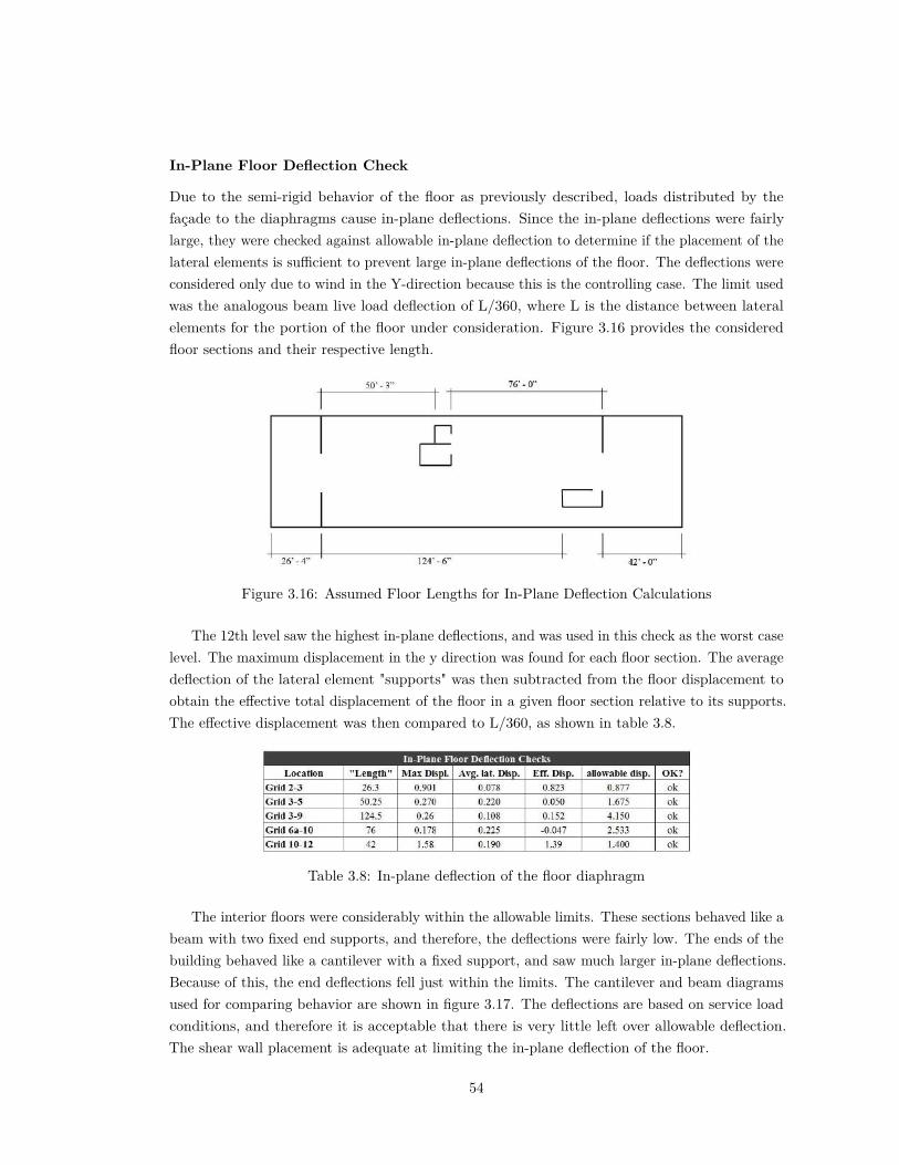
In-Plane Floor Deflection Check
Due to the semi-rigid behavior of the floor as previously described, loads distributed by thefaçade to the diaphragms cause in-plane deflections. Since the in-plane deflections were fairlylarge, they were checked against allowable in-plane deflection to determine if the placement of thelateral elements is su�cient to prevent large in-plane deflections of the floor. The deflections wereconsidered only due to wind in the Y-direction because this is the controlling case. The limit usedwas the analogous beam live load deflection of L/360, where L is the distance between lateralelements for the portion of the floor under consideration. Figure 3.16 provides the consideredfloor sections and their respective length.
Figure 3.16: Assumed Floor Lengths for In-Plane Deflection Calculations
The 12th level saw the highest in-plane deflections, and was used in this check as the worst caselevel. The maximum displacement in the y direction was found for each floor section. The averagedeflection of the lateral element "supports" was then subtracted from the floor displacement toobtain the e�ective total displacement of the floor in a given floor section relative to its supports.The e�ective displacement was then compared to L/360, as shown in table 3.8.
Table 3.8: In-plane deflection of the floor diaphragm
The interior floors were considerably within the allowable limits. These sections behaved like abeam with two fixed end supports, and therefore, the deflections were fairly low. The ends of thebuilding behaved like a cantilever with a fixed support, and saw much larger in-plane deflections.Because of this, the end deflections fell just within the limits. The cantilever and beam diagramsused for comparing behavior are shown in figure 3.17. The deflections are based on service loadconditions, and therefore it is acceptable that there is very little left over allowable deflection.The shear wall placement is adequate at limiting the in-plane deflection of the floor.
54
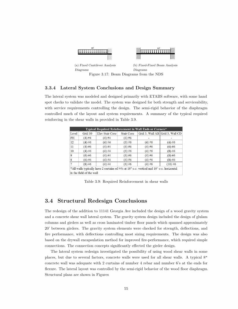
(a) Fixed Cantilever AnalysisDiagrams
(b) Fixed-Fixed Beam AnalysisDiagrams
Figure 3.17: Beam Diagrams from the NDS
3.3.4 Lateral System Conclusions and Design Summary
The lateral system was modeled and designed primarily with ETABS software, with some handspot checks to validate the model. The system was designed for both strength and serviceability,with service requirements controlling the design. The semi-rigid behavior of the diaphragmcontrolled much of the layout and system requirements. A summary of the typical requiredreinforcing in the shear walls in provided in Table 3.9.
Table 3.9: Required Reinforcement in shear walls
3.4 Structural Redesign ConclusionsThe redesign of the addition to 11141 Georgia Ave included the design of a wood gravity systemand a concrete shear wall lateral system. The gravity system design included the design of glulamcolumns and girders as well as cross laminated timber floor panels which spanned approximately20’ between girders. The gravity system elements were checked for strength, deflections, andfire performance, with deflections controlling most sizing requirements. The design was alsobased on the drywall encapsulation method for improved fire-performance, which required simpleconnections. The connection concepts significantly e�ected the girder design.
The lateral system redesign investigated the possibility of using wood shear walls in someplaces, but due to several factors, concrete walls were used for all shear walls. A typical 8"concrete wall was adequate with 2 curtains of number 4 rebar and number 6’s at the ends forflexure. The lateral layout was controlled by the semi-rigid behavior of the wood floor diaphragm.Structural plans are shown in Figures
55

Figure 3.18: Typical Level Structural Plan. Unless otherwise noted, girders are 15" deep typ.
56

Figure 3.19: Typical Level Structural Plan. Unless otherwise noted, girders are 18" deep typ.
57

Figure 3.20: Typical Level Structural Plan. Unless otherwise noted, girders are 15" deep typ.
58

4|Construction Breadth
4.1 IntroductionIn the construction management breadth, a cost and schedule analysis will be completed forthe existing and new addition. The schedule analysis will help determine scheduling di�erencesbetween the methods in order to identify any significant changes in schedule. The cost analysiswill provide a basis for investigating the economic feasibility of a wood-framed addition comparedto the costs of the existing steel addition. The focus of the cost analysis will be specifically on theexisting and new additions themselves, but will also take into account any significant changes togeneral conditions costs due to scheduling di�erences resulting from the shift from steel to woodfor the primary structural material.
4.2 Schedule AnalysisThe schedule analysis includes the determination of the schedule for both the existing andredesigned addition and a comparison between the two. Only the addition gravity systemstructure, partitions, and lateral system were included in the schedule analysis. The scheduleanalysis is based on determining the total time required for the items within the scope of theanalysis as well as an approximate schedule using RS Means Building Construction Cost Data2014 (Waier, 2014).
4.2.1 Existing Addition
The existing addition schedule used crew sizes and labor time values from RS Means to determinethe time required to construct the addition. The total time for construction of the entire additionis known to be 19 months, from February of 2013 to August of 2014. The resulting scheduleinformation for the existing steel addition is presented in figure 4.1, an approximate schedulewhich accounts for weekends and potential overlap of work. It was assumed that the next setof columns could not be installed until the concrete deck topping has cured for a week. It wasalso assumed that the partitions would not be installed on a level until the concrete fully curedto 28 days. Since the CMU walls are only in the original portion of the building, they can beconstructed concurrent with the addition.
59

Figure 4.1: Total scheduling time required for construction of existing addition
4.2.2 Redesigned Wood Addition
The redesigned wood addition uses CLT for the gravity system, which does not appear in RSMeans because it is relatively new to the US. In many resources, the construction process ofCLT panels is said to be similar to a pre-cast concrete panel system, so the CLT floor panel andpartition installation used RS Means data based on similar concrete panel sizes and types. Theresulting labor time and schedule is presented in figure 4.2. Since gravity system elements areprefabricated, the elements can be installed one after another. The concrete shear walls in theconcrete portion were not included in the schedule because their construction would most likelyoccur near the beginning of the project during renovation work.
4.2.3 Schedule Comparison
The schedule time for both the redesign and the existing building were compared to each other andto the total addition and renovation time line of 19 months. Based on the approximate schedules,the steel addition would take 9.5 months to construct, and the redesigned wood addition takesabout 4 months to construct. Therefore, the redesigned addition’s structure requires less thanhalf the schedule of the steel addition. The di�erence in scheduling is reasonable because thepre-fabricated panelized system can be installed much more quickly than the typical deck onbeam and joist system. A 5 month reduction in the construction time of the structural systemis significant when considering the original timeline of 19 months. A shorter schedule can have
60

Figure 4.2: Total scheduling time required for construction of existing addition
desirable benefits because the building can be open to use and can begin bringing in profit for theowner sooner.
4.3 Cost AnalysisThe cost analysis includes a unit cost estimate for both the existing and redesigned addition anda comparison between the two. The addition gravity system structure, partitions, and lateralsystem were included in the cost analysis. There may be some di�erences in cost due to theremoval of drop ceilings, changes to the fire protection systems, an alternate mechanical systemdue to lack of concealed spaces, and more, but the scope of the breadth will focus directly on thestructural costs. The cost analysis will also account for di�erences in general conditions costs dueto schedule di�erences.
4.3.1 Existing Addition
A unit cost method was used to estimate the cost in which each item was listed, quantified, andpriced for material and labor costs. The existing steel addition cost estimate included the itemsand quantities shown in table 4.1.
Cost data for the existing addition was all directly used from RS Means. The subtotal wasfound for all components within the scope of the construction management breadth. An estimated5 percent waste was added to materials that require in-field cutting or experience damage during
61

shipping and handling, including steel deck, welded wire fabric, and masonry units. Generalconditions was estimated to be an additional 10 percent of the subtotal based on RS Meanssuggestions. Sales tax was taken as 5.75 percent based on the Maryland state tax, and othercosts were added as per the recommendations in RS Means. The cost table for the existing steeladdition is shown in table 4.1. The total cost of the renovation and addition to 11141 GeorgiaAve is known to be approximately 44 million dollars.
Table 4.1: Cost analysis of existing steel addition
4.3.2 Redesigned Wood Addition
The unit cost method was also used in the wood addition to be consistent. The items and theirquantities used in the cost estimate are shown in table 4.2.
Most elements could be found in RS Means, however, a slightly more involved process wasused to determine the cost values for the CLT components of the building. Cost data fromStructurlam, a CLT manufacturer in the Canada and the US, was provided in Canadian dollars ina presentation discussing how to develop a CLT project (Green, 2012). The current exchange rateof 0.79 US cents for every Canadian dollar was used to convert that amount to US dollars. Sinceall elements are pre-fabricated, no factors were added to the material values for waste. Costswere also included for soundproofing the walls and floors since this will add a significant cost overthe steel addition, which doesn’t require the same level of sound insulation. General conditionswas taken to be 5 percent based on RS Means recommendations and the reduced schedule timefor the wood addition compared to the steel addition. All other cost additions are the same asmentioned before in the existing addition cost analysis. The cost table for the redesigned wood
62
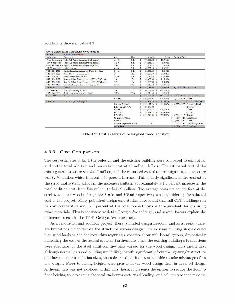
addition is shown in table 4.2.
Table 4.2: Cost analysis of redesigned wood addition
4.3.3 Cost Comparison
The cost estimates of both the redesign and the existing building were compared to each otherand to the total addition and renovation cost of 40 million dollars. The estimated cost of theexisting steel structure was $2.17 million, and the estimated cost of the redesigned wood structurewas $2.76 million, which is about a 30 percent increase. This is fairly significant in the context ofthe structural system, although the increase results in approximately a 1.5 percent increase in thetotal addition cost, from $44 million to $44.59 million. The average costs per square foot of thesteel system and wood redesign are $19.04 and $25.06 respectively when considering the subtotalcost of the project. Many published design case studies have found that tall CLT buildings canbe cost competitive within 5 percent of the total project costs with equivalent designs usingother materials. This is consistent with the Georgia Ave redesign, and several factors explain thedi�erence in cost in the 11141 Georgia Ave case study.
As a renovation and addition project, there is limited design freedom, and as a result, thereare limitations which dictate the structural system design. The existing building shape causedhigh wind loads on the addition, thus requiring a concrete shear wall lateral system, dramaticallyincreasing the cost of the lateral system. Furthermore, since the existing building’s foundationswere adequate for the steel addition, they also worked for the wood design. This meant thatalthough normally a wood building would likely benefit significantly from the lightweight structureand have smaller foundation sizes, the redesigned addition was not able to take advantage of itslow weight. Floor to ceiling heights were greater in the wood design than in the steel design.Although this was not explored within this thesis, it presents the option to reduce the floor tofloor heights, thus reducing the total enclosures cost, wind loading, and column size requirements.
63

Even with several factors, the wood design was not that much more expensive than the steeladdition, due to simpler connections and a quicker construction schedule.
The case study of the 11141 Georgia Ave addition suggests that a wood addition structuralsystem is cost competitive with a steel addition in the context of the overal project, but not whenlooking at the structural system itself. However, more design studies should be completed beforemaking generalizations. Other loading requirements and building configurations will significantlye�ect the cost of a wood structure alternative. Furthermore, if CLT buildings in the US aresuccessful enough to cause an increase in CLT construction, the cost of material and labor will godown as the amount of suppliers increases and the construction industry becomes more familiarwith the construction process. Therefore, although currently a wood addition is more expensive inthe case of the Georgia Ave apartment building, it is possible that prices will eventually decrease.
4.4 ConclusionsThe schedule analysis determined that the redesigned wood structure can be built in half the timeof the steel structure, while the cost analysis found that the wood system is about 30 percentgreater than the cost of the steel structure. Therefore, the wood design is feasible with regardsto cost and schedule when looking at the design holistically. Although the wood system is moreexpensive, it only adds approximately 1.5 percent to the total project cost, and depending on theowner’s needs this could potentially be worth it. The wood addition provides a reduced scheduletime, the opportunity to market the apartment building as more sustainable, and higher ceilingsresulting in apartments which feel larger and slightly more pleasing to occupants. If the exposedwood approach had been used, it may have been even more desirable to invest the extra cost intothe project since it would add a unique look to the apartments.
64

5|Mechanical Breadth
5.1 IntroductionSince no concealed spaces are allowed in heavy timber construction, the ductwork, wiring, andother mechanical systems which are normally hidden above a drop ceiling will be exposed. This isan important di�erence between the proposed wood redesign and the existing steel structure withdrop ceilings. Therefore, it is important for the mechanical equipment to be arranged aestheticallysuch that the apartments are just as appealing as in typical competing apartment buildings. Themechanical breadth will determine the changes that need to be made for aesthetic purposes andwill look in detail at one instance of an equipment location change and how that would a�ect costand the overall system.
5.2 Exposed Mechanical SystemsMechanical systems are typically concealed in walls and floor spaces. The benefits behind thispractice include; the ability to focus on the quality of the system rather than its looks, fewerinterior surfaces to clean, acoustical insulation from the sound of moving water and air, and morecontrol over the interior space design and aesthetics. Leaving the mechanical equipment exposedchallenges those benefits, however some benefits of exposed equipment includes a potential visualinterest and the ability to easily detect and repair leaks. (Walter T. Grondzik, 2010) Since theaesthetics of the concealed mechanical equipment is of interest in the redesign and aesthetics canbe somewhat subjective, design guidelines should be chosen to help make design decisions.
5.2.1 Case Studies
In order to determine the guidelines which will be used to make design decisions, a few casestudies of apartments with exposed mechanical equipment follow. The apartment in figure 5.1shows exposed mechanical, electrical, and plumbing equipment. The mechanical duct work iskept simple, following a straight line. It it tucked to the edge of the furthest room seen, andalthough it passes through the middle of the room closest to the viewer, it is placed along theimaginary border between the living room and kitchen space. The electrical equipment is also
65

fairly simple and takes only ninety degree turns when required. All equipment is painted white toblend into the white ceiling.
Figure 5.1: Example of exposed mechanical equipment. Source: Houzz.com
Figure 5.2 shows an apartment with exposed mechanical and electrical equipment. As with theprevious example, the mechanical duct work is simple and follows a straight path. The electricalconduit is also fairly simple, using straight lines and right angles where necessary, and using thebeam as a location for the equipment. Contrary to the previous example, the equipment has keptits original finishes and has not been painted. Here, it blends in with the gray ceiling, such thatit works aesthetically. The decision to leave the equipment bare and unpainted can be a designchoice which makes a space look more industrial, so the choice will generally be a matter of tasteand preference.
Figure 5.2: Example of exposed mechanical equipment. Source: Houzz.com
5.2.2 Design Guidelines
From the previous case study examples, certain design guidelines have been chosen to organize themechanical equipment aesthetically. It seems that no matter that aesthetic intent, it is importantfor the equipment to be kept as simple and straight as possible, and to make turns using ninetydegree turns. This guideline keeps the equipment from looking cluttered or disorganized.
66
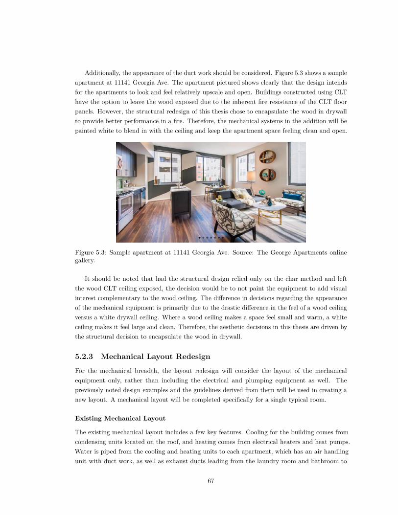
Additionally, the appearance of the duct work should be considered. Figure 5.3 shows a sampleapartment at 11141 Georgia Ave. The apartment pictured shows clearly that the design intendsfor the apartments to look and feel relatively upscale and open. Buildings constructed using CLThave the option to leave the wood exposed due to the inherent fire resistance of the CLT floorpanels. However, the structural redesign of this thesis chose to encapsulate the wood in drywallto provide better performance in a fire. Therefore, the mechanical systems in the addition will bepainted white to blend in with the ceiling and keep the apartment space feeling clean and open.
Figure 5.3: Sample apartment at 11141 Georgia Ave. Source: The George Apartments onlinegallery.
It should be noted that had the structural design relied only on the char method and leftthe wood CLT ceiling exposed, the decision would be to not paint the equipment to add visualinterest complementary to the wood ceiling. The di�erence in decisions regarding the appearanceof the mechanical equipment is primarily due to the drastic di�erence in the feel of a wood ceilingversus a white drywall ceiling. Where a wood ceiling makes a space feel small and warm, a whiteceiling makes it feel large and clean. Therefore, the aesthetic decisions in this thesis are driven bythe structural decision to encapsulate the wood in drywall.
5.2.3 Mechanical Layout Redesign
For the mechanical breadth, the layout redesign will consider the layout of the mechanicalequipment only, rather than including the electrical and plumping equipment as well. Thepreviously noted design examples and the guidelines derived from them will be used in creating anew layout. A mechanical layout will be completed specifically for a single typical room.
Existing Mechanical Layout
The existing mechanical layout includes a few key features. Cooling for the building comes fromcondensing units located on the roof, and heating comes from electrical heaters and heat pumps.Water is piped from the cooling and heating units to each apartment, which has an air handlingunit with duct work, as well as exhaust ducts leading from the laundry room and bathroom to
67

the exterior. A typical apartment is shown in figure 5.4 (a). The gypsum ceiling in the existingbuilding is typically installed up against the steel in most living room and bedroom areas. Theceiling is lowered to allow room for mechanical equipment in the bathroom and kitchen areas, asshown in a typical apartment plan in figure 5.4 (b).
(a) Single apartment mechanical plan outlinedin blue. Source: Mechanical Drawings
(b) Shaded portions show where ceiling islowered to leave room for equipment. Source:Architectural Drawings
Figure 5.4: Typical Apartment Layouts showing mechanical equipment and lowered ceiling
New Mechanical Layout
The new gravity structural system will have higher ceilings overall, but exposed girders. Therefore,in figure 5.4 (a), there will be a girder along the column line at the right side of the room, passingthrough the edge of the bedroom. The exhaust ductwork passes diagonally through some of therooms and across the girder, so changes will be made to those ducts in the new layout. The newlayout is shown in figure 5.5.
In the new typical layout, the exhaust ducts now each follow a path perpendicular over to thegirder. There, they will follow the girder line, tucked between the girder and the wall until theyreach the exterior. The existing air handling unit is fairly large and bulky, and would likely benoisier without a drop ceiling. Therefore, a new mechanical system was chosen in order to meetthe design guidelines determined previously.
A Variable Refrigerant Volume (VRV) system was chosen due to the small sizes of its pipingand equipment. Rather than using water or air to circulate cooled or heated material, this systemuses refrigerant, and is a more e�cient use of space. It is also a system which can be controlledon an individual apartment basis. The VRV system would have a similar layout to the existingsystem as condensing units are placed on the roof, and the chilled refrigerant is piped similar tothe water system to individual VRV unts in the apartments. Shown in figure 5.6 is a figure of a
68

Figure 5.5: New Mechanical Layout; Typical Apartment
typical VRV system layout, and the various available VRV units. The pipe size required for theGeorgia Ave apartments is 3/4".
Figure 5.6: Figure of typical VRV system layout possibilities. Source:
The existing system did not supply outside air to the apartments, and thus not additionaloutdoor supply air was provided in the redesign. The design used operable windows in theapartments to achieve outdoor air requirements.
The new mechanical system with therefore have a VRV wall unit. Figure 5.7 shows an existingapartment photo in (a) and a modified image proposing a sample apartment in (b). The new
69

apartment figure shows that some mechanical items will be seen, however they will be relativelysmall, sleek, and similar in color to their surroundings. The redesigned apartment in figure 5.7(b) also shows the slightly raised ceilings due to the redesigned structure. This helps place themechanical equipment even higher up so that it is not quite as noticeable.
(a) Sample Apartment before ceiling height and mechanical changes
(b) Sample Apartment after ceiling height and mechanical changesFigure 5.7: Comparison of e�ect of higher ceilings and exposed mechanical systems
5.3 ConclusionsThe mechanical breadth studied the implications of having no concealed spaces and leaving themechanical equipment exposed. The existing mechanical layout was altered such that beingexposed, it is relatively sleek and aesthetically pleasing and comparable to a typical equivalentapartment. A VRV system was used for its e�ciently and slimness, and sidewall units wereprovided in the apartments in the living room and bedroom so they can by controlled individually.Hand calculations for pipe sizings have been provided in Appendix D.
70
6|Conclusions
6.1 SummaryThe redesign of the addition to 11141 Georgia Ave included the design of a wood gravity systemand a concrete shear wall lateral system. The gravity system design included the design of glulamcolumns and girders as well as cross laminated timber floor panels which spanned approximately20’ between girders. The gravity system elements were checked for strength, deflections, andfire performance based on the encapsulation method, with deflections controlling most sizingrequirements. Concrete shear walls were designed for the lateral system, resulting in a typical 8"concrete wall which was adequate with 2 curtains typical of number 4 bars and number 6’s at theends for flexure. The lateral layout was controlled by the semi-rigid behavior of the wood floordiaphragm and serviceability.
The schedule analysis determined that the redesigned wood structure can be built in halfthe time of the steel structure, while the cost analysis found that the wood system is about 30percent greater than the cost of the steel structure adding 1.5 percent to the total project cost.Therefore, the wood design is feasible with regards to cost and schedule when looking at thedesign holistically, and depending on the owner’s needs the redesigned addition could be a feasiblealternate. The mechanical breadth studied the implications of having no concealed spaces andleaving the mechanical equipment exposed. The existing mechanical layout was altered suchthat being exposed, it is relatively sleek and aesthetically pleasing and comparable to a typicalequivalent apartment. A VRV system was used for its e�ciently and slimness, and sidewall unitswere provided.
6.2 Heavy Timber in the RedesignThe use of wood in the redesign has several significant e�ects on the design work, some, but notall, of which were fully explored in the work of this thesis. There are both challenges and benefitsto a taller wood building. Challenges in the redesign work included conceptual connection designfor the encapsulation method and lateral design of a system with a semi-rigid diaphragm. Thechallenges of using wood to build include design for fire safety, water protection of the woodelements during construction, sound and vibration performance, and more. Benefits in the work
71

of the thesis included achieving a more lightweight structure, a faster schedule, and higher ceilings.The benefits of using wood in construction include the sustainable nature of wood, architecturalinterest, and a competitive schedule. Although the wood alternate addition may be more or lessbeneficial for the owner depending on goals relating to cost schedule, and marketing, the additionis ultimately structurally feasible and could potentially be built to meet fire safety requirements.
72

A|Gravity System Calculations
A.1 IntroductionIncluded in this Appendix are all the calculations completed for both the existing gravity systemand the wood redesign gravity system. These calculations are provided to show more specificallywhat was done to reach the design choices and conclusions.
A.2 Existing Gravity SystemCalculations determining loads in the existing gravity system follow. The methods and processused for determining the gravity loads is described in chapter 1.
73

Figure A.1: Roof Load Calculations74

Figure A.2: Snow Load and Drift Calculations
75

Figure A.3: Floor Load Calculations
76

Figure A.4: Exterior Wall Load Calculations
77

Figure A.5: Non-Typical Load Calculations
78

A.3 Wood Redesign
A.3.1 CLT Panel Calculations
Included below are the excel tables used to determine final CLT panel sizes. These calculationsfollow the methods and process described in chapter 3.
Table A.1: CLT Panel Design for Typical bay
Table A.2: CLT Panel Design for 26’ bay
79

Typical Opening Calculation
Figure A.6: Typical Opening Calculations
80
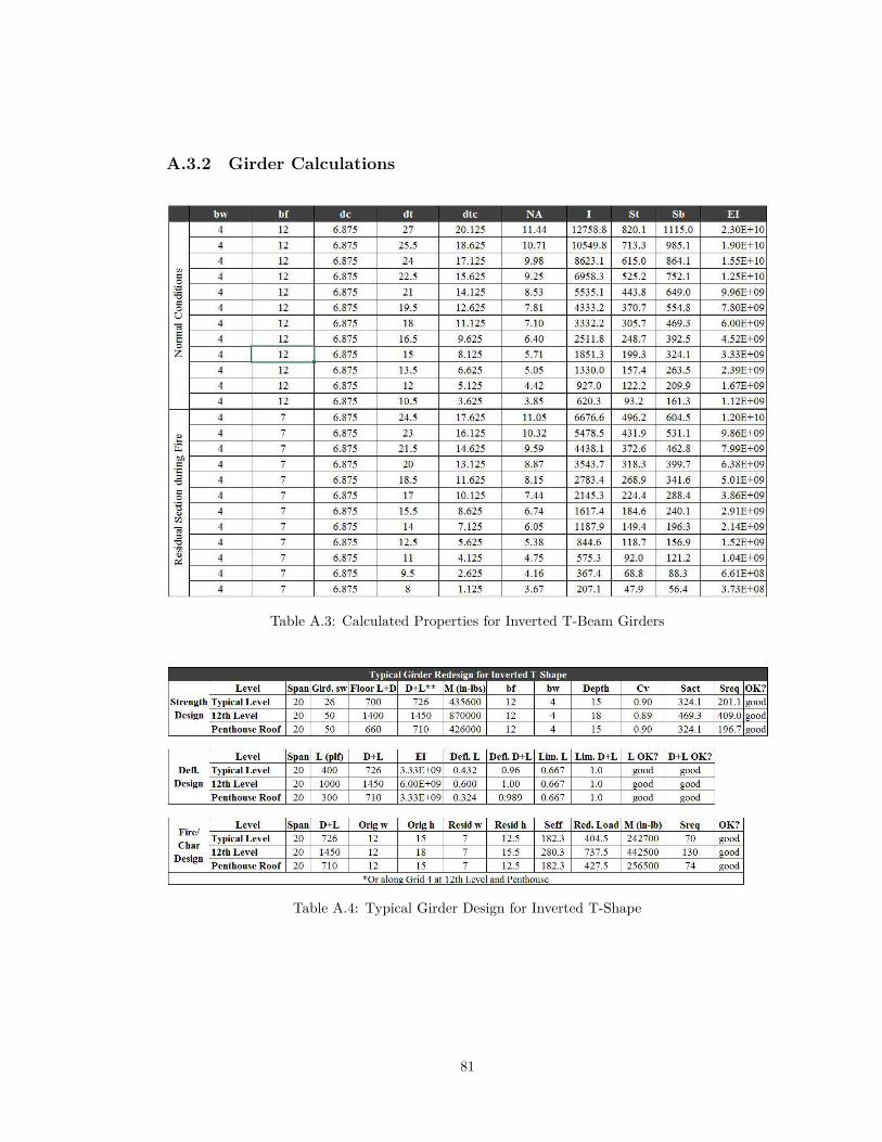
A.3.2 Girder Calculations
Table A.3: Calculated Properties for Inverted T-Beam Girders
Table A.4: Typical Girder Design for Inverted T-Shape
81

Table A.5: Non-typical Girder Design
Table A.6: Non-typical Girder Design
Table A.7: Non-typical Girder Design
82

A.3.3 Column Calculations
Figure A.7: Typical Column Calculations at Base of Addition
83

Figure A.8: Typical Column Calculations at Base of Addition
84

(a) General Column Design Information
(b) Exterior Wall Load InformationFigure A.9: General Column Design Information
85

Table A.8: Column Excel Calculations
86

B|Lateral System Redesign Calculations
B.1 IntroductionIncluded in this Appendix are all the calculations completed for both the existing lateral systemand the wood redesign lateral system. These calculations are provided to show more specificallywhat was done to reach the design choices and conclusions.
B.2 Existing Lateral SystemSample excel calculations determining loads in the existing lateral system follow. The methodsand process used for determining the lateral loads is described in chapter 1.
B.2.1 Wind Loads
87

Table B.1: Wind Load Excel Calculations
88

Table B.2: Wind Load Excel Calculations
89

Table B.3: Wind Load Excel Calculations
90

Table B.4: Wind Load Excel Calculations
91

B.2.2 Seismic Loads
Figure B.1: Seismic Load Calculations
92

Figure B.2: Seismic Load Calculations
93

Table B.5: Seismic Load Calculations
94

B.3 Wood RedesignIncluded below are the various hand calculation spot checks of the software and any relevantsoftware output for the redesigned lateral system.
Figure B.3: Shear Wall Spot Check
95

Figure B.4: Shear Wall Spot Check96

Figure B.5: Overturning Moment Check97

Figure B.6: In-plane deflection spot check98

C|Design Tables
C.1 IntroductionIncluded in this Appendix are the design value tables used in the gravity system redesign. Thepurpose of this appendix is to provide the specifically referenced tables used in this thesis.
Table C.1: CLT Material Design Values Table. Source: CLT Handbook.
99
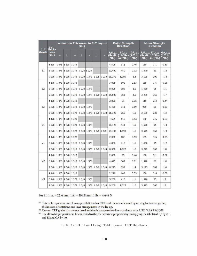
Table C.2: CLT Panel Design Table. Source: CLT Handbook.
100

Table C.3: Glulam Beam Design Table. Source: APA - The Engineered Wood Association
101

D|Breadth Calculations
D.1 IntroductionIncluded in this appendix are additional breadth tables and calculations.
D.1.1 Construction Management Breadth
Table D.1: Structurlam CLT costs given in Canadian dollars. Source: Michael Green’s Presentationon How to Develop a CLT Project
Table D.2: Quantities found for Steel Addition
102

Table D.3: Quantities found for Wood Addition
Table D.4: Scheduling time found for Steel Addition
Table D.5: Scheduling time found for Wood Addition
103

D.1.2 Mechanical Breadth
Figure D.1: Mechanical Equipment Sizing Calculations
104

Bibliography
AISC (2010). Steel Construction Manual (14th Edition ed.). American Institute of SteelConstruction.
American Wood Council (2015). National Design Specification for Wood Construction. AmericanWood Council.
APA - The Engineered Wood Association (2008). Glulam Design Specification. APA - TheEngineered Wood Association.
APA - The Engineered Wood Association (2009). Design of Structural Glued Laminated TimberColumns. APA - The Engineered Wood Association.
ASCE (2005). ASCE 7-05: Minimum Design Loads for Buildings and Other Structures. AS-CE/AEI.
Börjesson, P. and L. Gustavsson (2000). Greenhouse gas balances in building construction: woodversus concrete from life-cycle and forest land-use perspectives. Energy policy 28 (9), 575–588.
Edward Allen, J. I. (2009). Fundamentals of Building Construction; Materials and Methods (5thEdition ed.). John Wiley and Sons, Inc.
FPInnovations and B. S. L. Council (2013). CLT Handbook - Cross Laminated Timber (USEdition ed.). U.S. Department of Agriculture, Forest Service, Forest Products Laboratory,Binational Softwood Lumber Council.
Frangi, A., F. M. H. E. and R. Jobstl (2009). Experimental analysis of cross-laminated timberpanels in fire. Fire Safety Journal 44 (8), 1078–1087.
Gerard, R., D. Barber, and A. Wolski (2013, December). Fire safety challenges of tall woodbuildings. Technical report, Fire Protection Research Foundation.
Green, M. (2012). How to develop a clt project. Presentation Slides from a presentation sponsoredby Wood Works and the Canadian Wood Council.
Green, M. and E. Karsh (2012, February). The case for tall wood buildings. Technical report,MGB Architecture and Design.
Gustavsson, L. and R. Sathre (2006). Variability in energy and carbon dioxide balances of woodand concrete building materials. Building and Environment 41 (7), 940–951.
Hein, C. (2014). Developing hybrid timber construction for sustainable tall buildings. CTBUHJournal Issue III, 40–45.
SOM (2013, May). Timber tower research project. Technical report, Skidmore, Owings & Merrill,LLP.
105

Upton, B., R. Miner, M. Spinney, and L. S. Heath (2008). The greenhouse gas and energy impactsof using wood instead of alternatives in residential construction in the united states. Biomassand Bioenergy 32 (1), 1–10.
Waier, P. R. (2014). RS Means Building Construction Cost Data 2014. Reed Construction Data.
Walter T. Grondzik, A.G. Kwok, J. R. B. S. (2010). Mechanical and Electrical Equipment forBuildings. Wiley.
106

Academic VitaSamantha deVries
Education
Bachelor and Master of Architectural Engineering, Interdisciplinary SciencePennsylvania State University, State College, PA, expected December 2015Option: Structural Engineering
Software Skills
Software: ETABS, SAP 2000, Revit, STAAD, RISA 2D, RAM Concept and Structural System,Microsoft Excel
Experience
Rathgeber Goss Associates Summer 2014Structural Engineering Intern in Rockville, MD
• Assisted in design of new structures and renovations to existing structures• Prepared structural documents for submission and recorded the results at a concrete garage
survey
Appalachia Service Project Summers 2011-2013Center Director in Washington County, VA (Summer 2013)
• Managed the project schedule and $40,000 budget for 28 homes repaired in an ASP county
• Responsible for ensuring the quality work and continual improvement of 3 center sta�
Center Sta� in Letcher County, KY (Summer 2012) and Mingo County, WV (Summer 2011)
• Supervised 60-80 volunteers and managed building supplies for three projects weeklyinvolving emergency home repair and renovation
• Responsibilities include interviewing families for project selection, managing tool and supplyinventory, training volunteers in safety and quality building practices, and promoting positivecommunity relationships
Community Service
Volunteer Climbing Instructor at the State College, PA YMCAFoster community involvement in the sport of rock climbing by working with other volunteers asa belayer and instructor at the local YMCA
Extra-Curricular Activities
Cellist, Various Penn State Music Ensembles, fall 2010-presentSecretary, Penn State Student Chapter of the Structural Engineering Association, fall 2014-spring2015Member, Penn State Outing Club, spring 2011-presentPresident, Co-Founder, Global Architecture Brigades, fall 2011-spring 2013