Embed Size (px)
Citation preview
THE PEDRO AND INES FOOTBRIDGE AT COIMBRA - conception, design and construction -
António ADÃO DA FONSECA
Professor - Faculty of Engineering of the University of Porto Structural Engineer - Adão da Fonseca, Engenheiros Consultores, Lda. Porto, Portugal
Summary Urban and architectural planning, structural conception, design and dynamic behaviour of the Cycling and Pedestrian Bridge over the River Mondego, in the city of Coimbra, connecting the two sides of the park built along the two river margins, are described. Keywords: footbridge; steel bridge; urban planning; structural concept; structural design; construction method;
vibration control; tuned mass dumper; handrail; coloured glass.
1. Urban and architectural planning The Mondego River runs through the middle of the city of Coimbra before coursing unerringly westwards into the Atlantic Ocean. Immediately downstream from the city, there is a low dam creating a water basin which not only supplies irrigation water for fertile cultivated land on the margins of the river all the way down to its mouth, but also provides Coimbra with a refreshing lake of over 200 m in width, where water sports facilities are available. Coimbra is also a student city by excellence, and the margins of the river have always been a favourite haunt for students, where they can rest and daydream. River margins at Coimbra become very low and are often flooded during the winter season when rainfall is higher than normal. Therefore, building construction in Coimbra has always taken place some distance away from the river, and land right alongside the river has been preserved in its natural setting. Recently, that land was allocated to parkland with several social, leisure and cultural equipments, and crossing from one margin to the other is now a very pleasant promenade along the footbridge named after Prince Pedro and Lady-in-Waiting Ines, who were actors of a tragic medieval tale of love, passion and murder. Figure 1 reveals the very special solution designed for this bridge [1]. Both deck and arch split in two halves and shift transversally into parallel alignments with the two decks united along 12 m in the centre of the bridge, defining a central “piazza” where pedestrians tend to stop and relax while looking at the beautiful scenery going up the hills, with the Old University of Coimbra on the North side and the Carmelite Monastery on the South side.
Fig. 1 - Bird’s eye view of the bridge with elevation and plan reflected in the calm river waters
2. Bridge constraints The bridge had to allow practice of water sports such as rowing, sailing with small sailboats and windsurfing. With regard to rowing competitions, the design should make it possible to organise the course layout passing under the bridge. This type of constraints meant that deck and its supports had to provide a minimum free span of 81 m in width by 2 m minimum free height above the water level, and this was to rise to a height of 7 m for a length of 30 m. Furthermore, since pedestrian walkways along the river margins are only about 20 cm above the water level, the bridge deck has to be as low as possible. Naturally, a girder beam for that span length and at low height would make for an ungainly and heavy structure. Transparent and light solutions call for suspended-deck bridges or cable-stayed bridges. However, very close upstream there is a cable-stayed road bridge and the two bridges would then visually clash. Also, both suspension bridges and cable-stayed bridges are expensive to build and the cost thereof would largely exceed the available budget. In any case, the bridge has to offer a comfortable walkway for all types of users, including users with disabilities crossing on wheelchairs. And it was intended that a restful and relaxing atmosphere, overlooking the calm, lake-like water flow that is almost always a feature of the Mondego River, could be enjoyed along the whole of the bridge. Indeed, a pedestrian bridge must be more than a simple crossing pathway above the water.
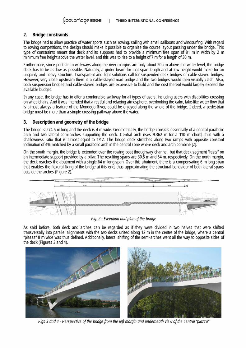
3. Description and geometry of the bridge The bridge is 274.5 m long and the deck is 4 m wide. Geometrically, the bridge consists essentially of a central parabolic arch and two lateral semi-arches supporting the deck. Central arch rises 9.362 m for a 110 m chord, thus with a shallowness ratio that is almost equal to 1/12. The bridge deck stretches along two ramps with opposite constant inclination of 4% matched by a small parabolic arch in the central zone where deck and arch combine [2]. On the south margin, the bridge is extended over the rowing boat throughway channel, but that deck segment “rests” on an intermediate support provided by a pillar. The resulting spans are 30.5 m and 64 m, respectively. On the north margin, the deck reaches the abutment with a single 64 m long span. Over this abutment, there is a compensating 6 m long span that enables the flexural fixing of the bridge at this end, thus approximating the structural behaviour of both lateral spans outside the arches (Figure 2).
Fig. 2 - Elevation and plan of the bridge
As said before, both deck and arches can be regarded as if they were divided in two halves that were shifted transversally into parallel alignments with the two decks united along 12 m in the centre of the bridge, where a central “piazza” 8 m wide was thus defined. Additionally, lateral shifting of the semi-arches went all the way to opposite sides of the deck (Figures 3 and 4).
Figs 3 and 4 - Perspective of the bridge from the left margin and underneath view of the central “piazza”
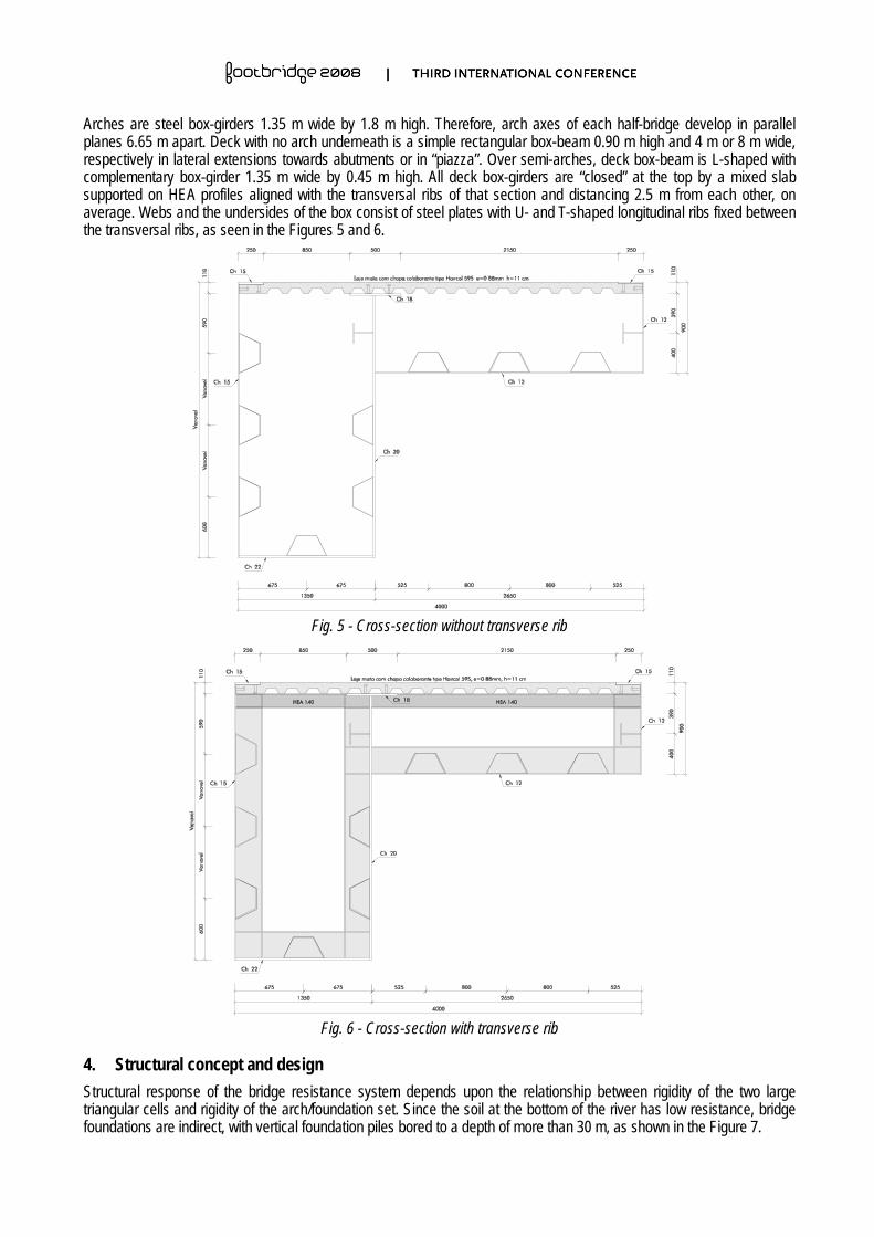
Arches are steel box-girders 1.35 m wide by 1.8 m high. Therefore, arch axes of each half-bridge develop in parallel planes 6.65 m apart. Deck with no arch underneath is a simple rectangular box-beam 0.90 m high and 4 m or 8 m wide, respectively in lateral extensions towards abutments or in “piazza”. Over semi-arches, deck box-beam is L-shaped with complementary box-girder 1.35 m wide by 0.45 m high. All deck box-girders are “closed” at the top by a mixed slab supported on HEA profiles aligned with the transversal ribs of that section and distancing 2.5 m from each other, on average. Webs and the undersides of the box consist of steel plates with U- and T-shaped longitudinal ribs fixed between the transversal ribs, as seen in the Figures 5 and 6.
Fig. 5 - Cross-section without transverse rib
Fig. 6 - Cross-section with transverse rib
4. Structural concept and design Structural response of the bridge resistance system depends upon the relationship between rigidity of the two large triangular cells and rigidity of the arch/foundation set. Since the soil at the bottom of the river has low resistance, bridge foundations are indirect, with vertical foundation piles bored to a depth of more than 30 m, as shown in the Figure 7.
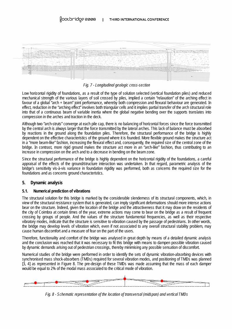
Fig. 7 - Longitudinal geologic cross-section
Low horizontal rigidity of foundations, as a result of the type of solution selected (vertical foundation piles) and reduced mechanical strength of the various layers of soil crossed by piles, implied a certain “relaxation” of the arching effect in favour of a global “arch + beam” joint performance, whereby both compression and flexural behaviour are generated. In effect, reduction in the “arching effect” involves both triangular cells and it implies partial transfer of the arch structural role into that of a continuous beam of variable inertia where the global negative bending over the supports translates into compression in the arches and traction in the deck. Although two “arch-struts” converge at each pile cap, there is no balancing of horizontal forces since the force transmitted by the central arch is always larger that the force transmitted by the lateral arches. This lack of balance must be absorbed by reactions in the ground along the foundation piles. Therefore, the structural performance of the bridge is highly dependent on the effective characteristics of the ground where it is founded. More flexible ground makes the structure act in a “more beam-like” fashion, increasing the flexural effect and, consequently, the required size of the central zone of the bridge. In contrast, more rigid ground makes the structure act more in an “arch-like” fashion, thus contributing to an increase in compression on the arch and to a decrease in bending on the beam zone. Since the structural performance of the bridge is highly dependent on the horizontal rigidity of the foundations, a careful appraisal of the effects of the ground/structure interaction was undertaken. In that regard, parametric analysis of the bridge’s sensitivity vis-à-vis variance in foundation rigidity was performed, both as concerns the required size for the foundations and as concerns ground characteristics.
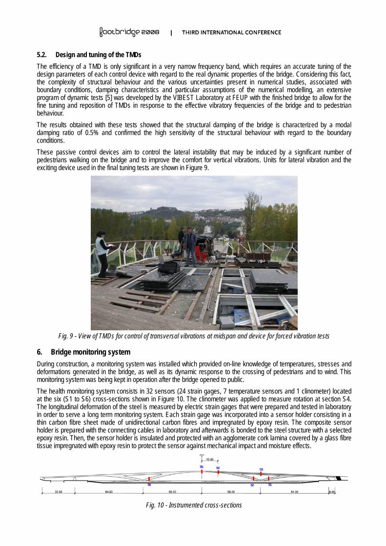
5. Dynamic analysis 5.1. Numerical prediction of vibrations The structural solution for this bridge is marked by the considerable slenderness of its structural components, which, in view of the structural resistance system that is generated, can imply significant deformations should more intense actions bear on the structure. Indeed, given the location of the bridge and the attractiveness that it may draw on the residents of the city of Coimbra at certain times of the year, extreme actions may come to bear on the bridge as a result of frequent crossing by groups of people. And the values of the structure fundamental frequencies, as well as their respective vibratory modes, indicate that the structure is sensitive to vibration caused by the passage of pedestrians. In other words, the bridge may develop levels of vibration which, even if not associated to any overall structural stability problem, may cause human discomfort and a measure of fear on the part of the users. Therefore, functionality and comfort of the bridge was analysed in great depth by means of a detailed dynamic analysis and the conclusion was reached that it was necessary to fit this bridge with means to dampen possible vibration caused by dynamic demands arising out of pedestrian crossings, thereby minimising any possible sensation of discomfort. Numerical studies of the bridge were performed in order to identify the sets of dynamic vibration-absorbing devices with synchronised mass shock-absorbers (TMDs) required for several vibration modes, and positioning of TMDs was planned [3, 4] as represented in Figure 8. The pre-design of these TMDs was made assuming that the mass of each damper would be equal to 2% of the modal mass associated to the critical mode of vibration.
Fig. 8 - Schematic representation of the location of transversal (midspan) and vertical TMDs
5.2. Design and tuning of the TMDs The efficiency of a TMD is only significant in a very narrow frequency band, which requires an accurate tuning of the design parameters of each control device with regard to the real dynamic properties of the bridge. Considering this fact, the complexity of structural behaviour and the various uncertainties present in numerical studies, associated with boundary conditions, damping characteristics and particular assumptions of the numerical modelling, an extensive program of dynamic tests [5] was developed by the VIBEST Laboratory at FEUP with the finished bridge to allow for the fine tuning and reposition of TMDs in response to the effective vibratory frequencies of the bridge and to pedestrian behaviour. The results obtained with these tests showed that the structural damping of the bridge is characterized by a modal damping ratio of 0.5% and confirmed the high sensitivity of the structural behaviour with regard to the boundary conditions. These passive control devices aim to control the lateral instability that may be induced by a significant number of pedestrians walking on the bridge and to improve the comfort for vertical vibrations. Units for lateral vibration and the exciting device used in the final tuning tests are shown in Figure 9.
Fig. 9 - View of TMDs for control of transversal vibrations at midspan and device for forced vibration tests
6. Bridge monitoring system During construction, a monitoring system was installed which provided on-line knowledge of temperatures, stresses and deformations generated in the bridge, as well as its dynamic response to the crossing of pedestrians and to wind. This monitoring system was being kept in operation after the bridge opened to public. The health monitoring system consists in 32 sensors (24 strain gages, 7 temperature sensors and 1 clinometer) located at the six (S1 to S6) cross-sections shown in Figure 10. The clinometer was applied to measure rotation at section S4. The longitudinal deformation of the steel is measured by electric strain gages that were prepared and tested in laboratory in order to serve a long term monitoring system. Each strain gage was incorporated into a sensor holder consisting in a thin carbon fibre sheet made of unidirectional carbon fibres and impregnated by epoxy resin. The composite sensor holder is prepared with the connecting cables in laboratory and afterwards is bonded to the steel structure with a selected epoxy resin. Then, the sensor holder is insulated and protected with an agglomerate cork lamina covered by a glass fibre tissue impregnated with epoxy resin to protect the sensor against mechanical impact and moisture effects.
S4 S5
S1
S3
S2 S6
Fig. 10 - Instrumented cross-sections
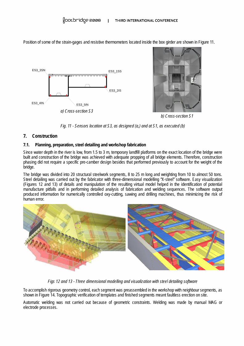
Position of some of the strain-gages and resistive thermometers located inside the box girder are shown in Figure 11.
ES3_3SN ES3_1SS
ES3_2IS
ES3_4IN ES3_5IN
Ponte da Europa
Ponte daSta Clara
a) Cross-section S3 b) Cross-section S1
Fig. 11 - Sensors location at S3, as designed (a,) and at S1, as executed (b)
7. Construction 7.1. Planning, preparation, steel detailing and workshop fabrication Since water depth in the river is low, from 1.5 to 3 m, temporary landfill platforms on the exact location of the bridge were built and construction of the bridge was achieved with adequate propping of all bridge elements. Therefore, construction phasing did not require a specific pre-camber design besides that performed previously to account for the weight of the bridge. The bridge was divided into 20 structural steelwork segments, 8 to 25 m long and weighting from 10 to almost 50 tons. Steel detailing was carried out by the fabricator with three-dimensional modelling “X-steel” software. Easy visualization (Figures 12 and 13) of details and manipulation of the resulting virtual model helped in the identification of potential manufacture pitfalls and in performing detailed analysis of fabrication and welding sequences. The software output produced information for numerically controlled oxy-cutting, sawing and drilling machines, thus minimizing the risk of human error.
Figs 12 and 13 - Three dimensional modelling and visualization with steel detailing software
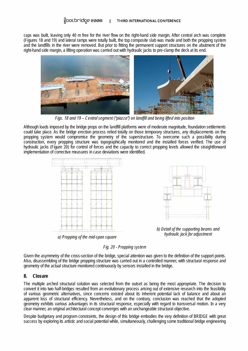
To accomplish rigorous geometry control, each segment was preassembled in the workshop with neighbour segments, as shown in Figure 14. Topographic verification of templates and finished segments meant faultless erection on site. Automatic welding was not carried out because of geometric constraints. Welding was made by manual MAG or electrode processes.
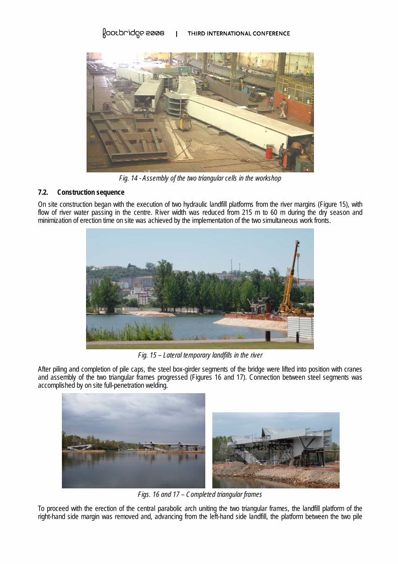
Fig. 14 - Assembly of the two triangular cells in the workshop
7.2. Construction sequence On site construction began with the execution of two hydraulic landfill platforms from the river margins (Figure 15), with flow of river water passing in the centre. River width was reduced from 215 m to 60 m during the dry season and minimization of erection time on site was achieved by the implementation of the two simultaneous work fronts.
Fig. 15 – Lateral temporary landfills in the river
After piling and completion of pile caps, the steel box-girder segments of the bridge were lifted into position with cranes and assembly of the two triangular frames progressed (Figures 16 and 17). Connection between steel segments was accomplished by on site full-penetration welding.
Figs. 16 and 17 – Completed triangular frames
To proceed with the erection of the central parabolic arch uniting the two triangular frames, the landfill platform of the right-hand side margin was removed and, advancing from the left-hand side landfill, the platform between the two pile
caps was built, leaving only 40 m free for the river flow on the right-hand side margin. After central arch was complete (Figures 18 and 19) and lateral ramps were totally built, the top composite slab was made and both the propping system and the landfills in the river were removed. But prior to fitting the permanent support structures on the abutment of the right-hand side margin, a lifting operation was carried out with hydraulic jacks to pre-clamp the deck at its end.
Figs. 18 and 19 – Central segment (“piazza”) on landfill and being lifted into position
Although loads imposed by the bridge props on the landfill platforms were of moderate magnitude, foundation settlements could take place. As the bridge erection process relied totally on those temporary structures, any displacements on the propping system would compromise the geometry of the superstructure. To overcome such a possibility during construction, every propping structure was topographically monitored and the installed forces verified. The use of hydraulic jacks (Figure 20) for control of forces and the capacity to correct propping levels allowed the straightforward implementation of corrective measures in case deviations were identified.
a) Propping of the mid-span square
b) Detail of the supporting beams and hydraulic jack for adjustment
Fig. 20 - Propping system
Given the asymmetry of the cross-section of the bridge, special attention was given to the definition of the support points. Also, disassembling of the bridge propping structure was carried out in a controlled manner, with structural response and geometry of the actual structure monitored continuously by sensors installed in the bridge.
8. Closure The multiple arched structural solution was selected from the outset as being the most appropriate. The decision to convert it into two half-bridges resulted from an evolutionary process arising out of extensive research into the feasibility of various geometric alternatives, since concerns existed about its inherent potential lack of balance and about an apparent loss of structural efficiency. Nevertheless, and on the contrary, conclusion was reached that the adopted geometry exhibits various advantages in its structural response, especially with regard to transversal motion. In a very clear manner, an original architectural concept converges with an unchangeable structural objective. Despite budgetary and program constraints, the design of this bridge embodies the very definition of BRIDGE with great success by exploring its artistic and social potential while, simultaneously, challenging some traditional bridge engineering
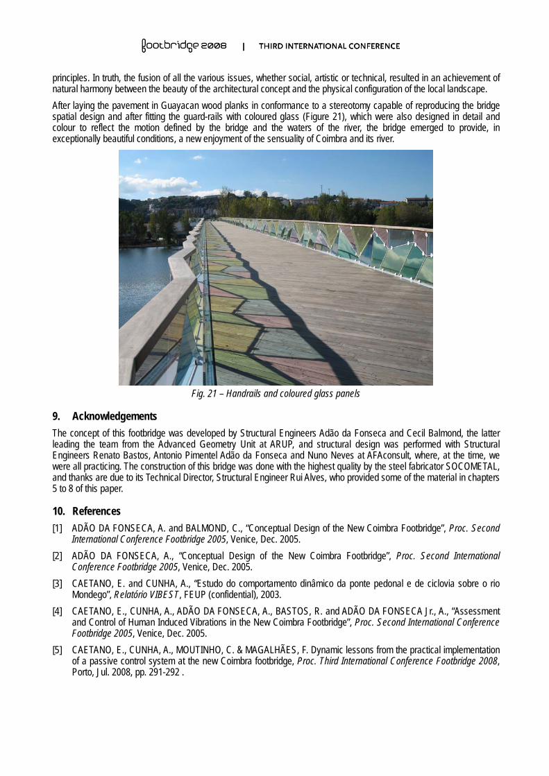
principles. In truth, the fusion of all the various issues, whether social, artistic or technical, resulted in an achievement of natural harmony between the beauty of the architectural concept and the physical configuration of the local landscape. After laying the pavement in Guayacan wood planks in conformance to a stereotomy capable of reproducing the bridge spatial design and after fitting the guard-rails with coloured glass (Figure 21), which were also designed in detail and colour to reflect the motion defined by the bridge and the waters of the river, the bridge emerged to provide, in exceptionally beautiful conditions, a new enjoyment of the sensuality of Coimbra and its river.
Fig. 21 – Handrails and coloured glass panels
9. Acknowledgements The concept of this footbridge was developed by Structural Engineers Adão da Fonseca and Cecil Balmond, the latter leading the team from the Advanced Geometry Unit at ARUP, and structural design was performed with Structural Engineers Renato Bastos, Antonio Pimentel Adão da Fonseca and Nuno Neves at AFAconsult, where, at the time, we were all practicing. The construction of this bridge was done with the highest quality by the steel fabricator SOCOMETAL, and thanks are due to its Technical Director, Structural Engineer Rui Alves, who provided some of the material in chapters 5 to 8 of this paper.
10. References [1] ADÃO DA FONSECA, A. and BALMOND, C., “Conceptual Design of the New Coimbra Footbridge”, Proc. Second
International Conference Footbridge 2005, Venice, Dec. 2005. [2] ADÃO DA FONSECA, A., “Conceptual Design of the New Coimbra Footbridge”, Proc. Second International
Conference Footbridge 2005, Venice, Dec. 2005. [3] CAETANO, E. and CUNHA, A., “Estudo do comportamento dinâmico da ponte pedonal e de ciclovia sobre o rio
Mondego”, Relatório VIBEST, FEUP (confidential), 2003. [4] CAETANO, E., CUNHA, A., ADÃO DA FONSECA, A., BASTOS, R. and ADÃO DA FONSECA Jr., A., “Assessment
and Control of Human Induced Vibrations in the New Coimbra Footbridge”, Proc. Second International Conference Footbridge 2005, Venice, Dec. 2005.
[5] CAETANO, E., CUNHA, A., MOUTINHO, C. & MAGALHÃES, F. Dynamic lessons from the practical implementation of a passive control system at the new Coimbra footbridge, Proc. Third International Conference Footbridge 2008, Porto, Jul. 2008, pp. 291-292 .


![PLAYING STRUCTURAL EFFICIENCY WITH ARCHITECTS · not "cuteness", not colourful or arrogant rhetoric. [7] 3. Pedro e Inês Footbridge in Coimbra, Portugal Open to the public in 2006,](https://img.pdfslide.us/doc/110x75/5f2bad14d44d0d2e0b4fd459/playing-structural-efficiency-with-architects-not-cuteness-not-colourful.jpg)