Embed Size (px)
Citation preview
Page 1255
The PC Game Adapter Chapter 24
One need look no farther than the internals of several popular games on the PC to discover thanmany programmers do not fully understand one of the least complex devices attached to the PC today –the analog game adapter. This device allows a user to connect up to four resistive potentiometers and fourdigital switch connections to the PC. The design of the PC’s game adapter was obviously influenced by theanalog input capabilities of the Apple II computer
1
, the most popular computer available at the time thePC was developed. Although IBM provided for twice the analog inputs of the Apple II, thinking thatwould give them an edge, their decision to support only four switches and four potentiometers (or “pots”)seems confining to game designers today – in much the same way that IBM’s decision to support 256KRAM seems so limiting today. Nevertheless, game designers have managed to create some really marvel-ous products, even living with the limitations of IBM’s 1981 design.
IBM’s analog input design, like Apple’s, was designed to be dirt cheap. Accuracy and performancewere not a concern at all. In fact, you can purchase the electronic parts to build your own version of thegame adapter, at retail, for under three dollars. Indeed, today you can purchase a game adapter card fromvarious discount merchants for under eight dollars. Unfortunately, IBM’s low-cost design in 1981 producessome major performance problems for high-speed machines and high-performance game software in the1990’s. However, there is no use crying over spilled milk – we’re stuck with the original game adapterdesign, we need to make the most of it. The following sections will describe how to do exactly that.
24.1 Typical Game Devices
The game adapter is nothing more than a computer interface to various game input devices. Thegame adapter card typically contains a DB15 connector into which you plug an external device. Typicaldevices you can obtain for the game adapter include
paddles, joysticks, flight yokes, digital joysticks, rud-der pedals, RC simulators,
and
steering wheels.
Undoubtedly, this is but a short list of the types of devicesyou can connect to the game adapter. Most of these devices are far more expensive that the game adaptercard itself. Indeed, certain high performance flight simulator consoles for the game adapter cost severalhundred dollars.
The digital joystick is probably the least complex device you can connect to the PC’s game port. Thisdevice consists of four switches and a stick. Pushing the stick forward, left, right, or pulling it backwardcloses one of the switches. The game adapter card provides four switch inputs, so you can sense whichdirection (including the rest position) the user is pressing the digital joystick. Most digital joysticks alsoallow you to sense the in-between positions by closing two contacts at once. for example, pushing thecontrol stick at a 45 degree angle between forward and right closes both the forward and right switches.The application software can sense this and take appropriate action. The original allure of these devices isthat they were very cheap to manufacture (these were the original joysticks found on most home gamemachines). However, as manufacturers increased production of analog joysticks, the price fell to the pointthat digital joysticks failed to offer a substantial price difference. So today, you will rarely encounter suchdevices in the hands of a typical user.
The game paddle is another device whose use has declined over the years. A game paddle is a singlepot in a case with a single knob (and, typically, a single push button). Apple used to ship a pair of gamepaddles with every Apple II they sold. As a result, games that used game paddles were still quite popularwhen IBM released the PC in 1981. Indeed, a couple manufacturers produced game paddles for the PCwhen it was first introduced. However, once again the cost of manufacturing analog joysticks fell to thepoint that paddles couldn’t compete. Although paddles are the appropriate input device for many games,joysticks could do just about everything a game paddle could, and more. So the use of game paddlesquickly died out. There is one thing you can do with game paddles that you cannot do with joysticks – you
1. In fact, the PC’s game adapter design was obviously stolen directly from the Apple II.
Thi d t t d ith F M k 4 0 2
Chapter 24
Page 1256
can place four of them on a system and produce a four player game. However, this (obviously) isn’timportant to most game designers who generally design their games for only one player.
Rudder pedals are really nothing more than a specially designed game paddle designed so you canactivate them with your feet. Many flight simulator games take advantage of this input device to provide amore realistic experience. Generally, you would use rudder pedals in addition to a joystick device.
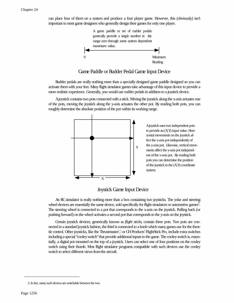
A joystick contains two pots connected with a stick. Moving the joystick along the x-axis actuates oneof the pots, moving the joystick along the y-axis actuates the other pot. By reading both pots, you canroughly determine the absolute position of the pot within its working range.
An RC simulator is really nothing more than a box containing two joysticks. The yoke and steeringwheel devices are essentially the same device, sold specifically for flight simulators or automotive games
2
.The steering wheel is connected to a pot that corresponds to the x-axis on the joystick. Pulling back (orpushing forward) on the wheel activates a second pot that corresponds to the y-axis on the joystick.
Certain joystick devices, generically known as
flight sticks
, contain three pots. Two pots are con-nected in a standard joystick fashion, the third is connected to a knob which many games use for the throt-tle control. Other joysticks, like the Thrustmaster
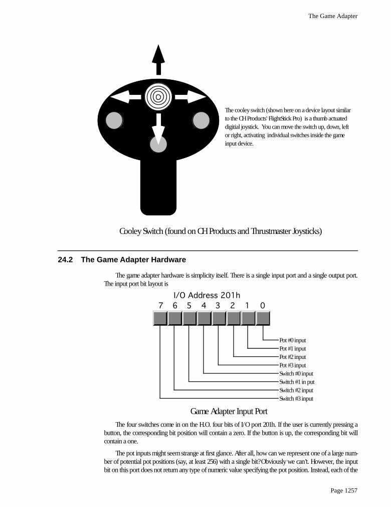
or CH Products’ FlightStick Pro, include extra switchesincluding a special “cooley switch” that provide additional inputs to the game. The cooley switch is, essen-tially, a digital pot mounted on the top of a joystick. Users can select one of four positions on the cooleyswitch using their thumb. Most flight simulator programs compatible with such devices use the cooleyswitch to select different views from the aircraft.
2. In fact, many such devices are switchable between the two.
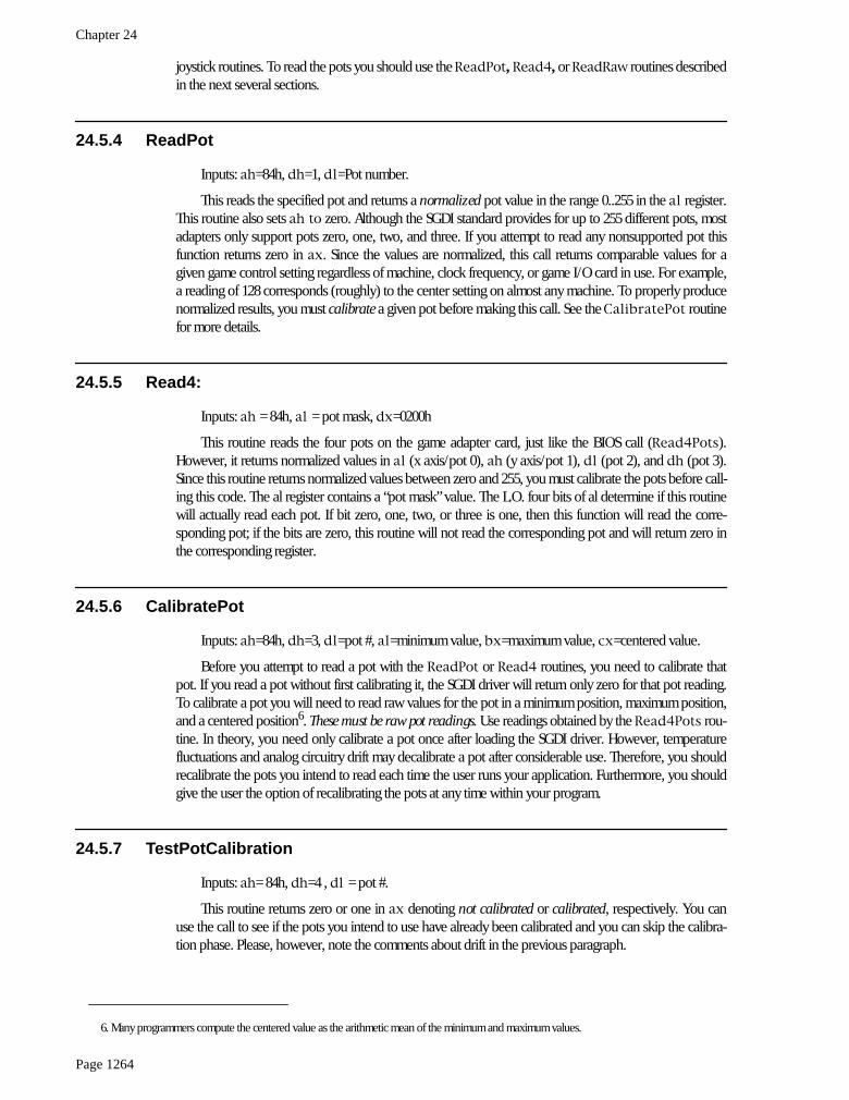
0 MaximumReading
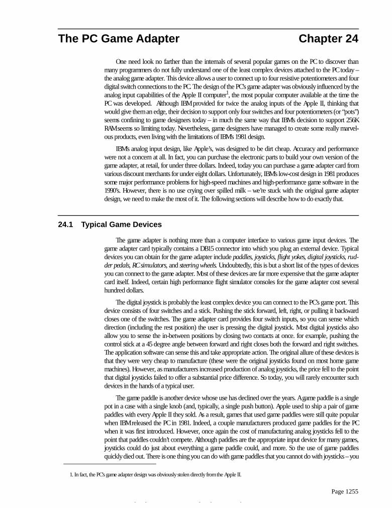
A game paddle or set of rudder pedalsgenerally provide a single number in therange zero through some system dependentmaximum value.
Game Paddle or Rudder Pedal Game Input Device
Y
X
A joystick uses two independent potsto provide an (X,Y) input value. Hori-zontal movements on the joystick af-fect the x-axis pot independently ofthe y-axis pot. Likewise, vertical move-ments affect the y-axis pot independ-ent of the x-axis pot. By reading bothpots you can determine the positionof the joystick in the (X,Y) coordinatesystem.
Joystick Game Input Device
The Game Adapter
Page 1257
24.2 The Game Adapter Hardware
The game adapter hardware is simplicity itself. There is a single input port and a single output port.The input port bit layout is
The four switches come in on the H.O. four bits of I/O port 201h. If the user is currently pressing abutton, the corresponding bit position will contain a zero. If the button is up, the corresponding bit willcontain a one.
The pot inputs might seem strange at first glance. After all, how can we represent one of a large num-ber of potential pot positions (say, at least 256) with a single bit? Obviously we can’t. However, the inputbit on this port does not return any type of numeric value specifying the pot position. Instead, each of the
The cooley switch (shown here on a device layout similarto the CH Products' FlightStick Pro) is a thumb actuateddigitial joystick. You can move the switch up, down, leftor right, activating individual switches inside the gameinput device.
Cooley Switch (found on CH Products and Thrustmaster Joysticks)
Pot #0 inputPot #1 inputPot #2 inputPot #3 inputSwitch #0 inputSwitch #1 in putSwitch #2 inputSwitch #3 input
Game Adapter Input Port
7 6 5 4 3 2 1 0I/O Address 201h
Chapter 24
Page 1258
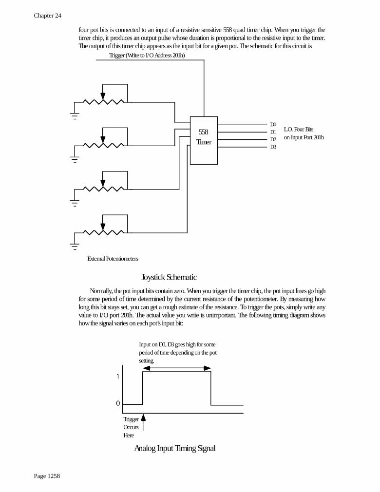
four pot bits is connected to an input of a resistive sensitive 558 quad timer chip. When you trigger thetimer chip, it produces an output pulse whose duration is proportional to the resistive input to the timer.The output of this timer chip appears as the input bit for a given pot. The schematic for this circuit is
Normally, the pot input bits contain zero. When you trigger the timer chip, the pot input lines go highfor some period of time determined by the current resistance of the potentiometer. By measuring howlong this bit stays set, you can get a rough estimate of the resistance. To trigger the pots, simply write anyvalue to I/O port 201h. The actual value you write is unimportant. The following timing diagram showshow the signal varies on each pot’s input bit:
558Timer
Trigger (Write to I/O Address 201h)
D0D1D2D3
External Potentiometers
Joystick Schematic
L.O. Four Bitson Input Port 201h
TriggerOccursHere
Input on D0..D3 goes high for someperiod of time depending on the potsetting.
0
1
Analog Input Timing Signal
The Game Adapter
Page 1259
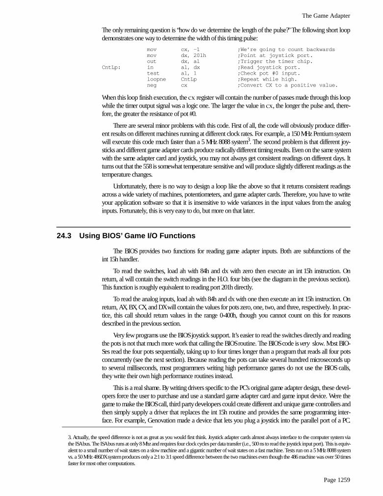
The only remaining question is “how do we determine the length of the pulse?” The following short loopdemonstrates one way to determine the width of this timing pulse:
mov cx, -1 ;We’re going to count backwardsmov dx, 201h ;Point at joystick port.out dx, al ;Trigger the timer chip.
CntLp: in al, dx ;Read joystick port.test al, 1 ;Check pot #0 input.loopne CntLp ;Repeat while high.neg cx ;Convert CX to a positive value.
When this loop finish execution, the
cx
register will contain the number of passes made through this loopwhile the timer output signal was a logic one. The larger the value in
cx
, the longer the pulse and, there-fore, the greater the resistance of pot #0.
There are several minor problems with this code. First of all, the code will obviously produce differ-ent results on different machines running at different clock rates. For example, a 150 MHz Pentium systemwill execute this code much faster than a 5 MHz 8088 system
3
. The second problem is that different joy-sticks and different game adapter cards produce radically different timing results. Even on the same systemwith the same adapter card and joystick, you may not always get consistent readings on different days. Itturns out that the 558 is somewhat temperature sensitive and will produce slightly different readings as thetemperature changes.
Unfortunately, there is no way to design a loop like the above so that it returns consistent readingsacross a wide variety of machines, potentiometers, and game adapter cards. Therefore, you have to writeyour application software so that it is insensitive to wide variances in the input values from the analoginputs. Fortunately, this is very easy to do, but more on that later.
24.3 Using BIOS’ Game I/O Functions
The BIOS provides two functions for reading game adapter inputs. Both are subfunctions of theint 15h handler.
To read the switches, load ah with 84h and dx with zero then execute an int 15h instruction. Onreturn, al will contain the switch readings in the H.O. four bits (see the diagram in the previous section).This function is roughly equivalent to reading port 201h directly.
To read the analog inputs, load ah with 84h and dx with one then execute an int 15h instruction. Onreturn, AX, BX, CX, and DX will contain the values for pots zero, one, two, and three, respectively. In prac-tice, this call should return values in the range 0-400h, though you cannot count on this for reasonsdescribed in the previous section.
Very few programs use the BIOS joystick support. It’s easier to read the switches directly and readingthe pots is not that much more work that calling the BIOS routine. The BIOS code is
very
slow. Most BIO-Ses read the four pots sequentially, taking up to four times longer than a program that reads all four potsconcurrently (see the next section). Because reading the pots can take several hundred microseconds upto several milliseconds, most programmers writing high performance games do not use the BIOS calls,they write their own high performance routines instead.
This is a real shame. By writing drivers specific to the PC’s original game adapter design, these devel-opers force the user to purchase and use a standard game adapter card and game input device. Were thegame to make the BIOS call, third party developers could create different and unique game controllers andthen simply supply a driver that replaces the int 15h routine and provides the same programming inter-face. For example, Genovation made a device that lets you plug a joystick into the parallel port of a PC.
3. Actually, the speed difference is not as great as you would first think. Joystick adapter cards almost always interface to the computer system viathe ISA bus. The ISA bus runs at only 8 Mhz and requires four clock cycles per data transfer (i.e., 500 ns to read the joystick input port). This is equiv-alent to a small number of wait states on a slow machine and a gigantic number of wait states on a fast machine. Tests run on a 5 MHz 8088 systemvs. a 50 MHz 486DX system produces only a 2:1 to 3:1 speed difference between the two machines even though the 486 machine was over 50 timesfaster for most other computations.
Chapter 24
Page 1260
Colorado Spectrum created a similar device that lets you plug a joystick into the serial port. Both deviceswould let you use a joystick on machines that do not (and, perhaps, cannot) have a game adapterinstalled. However, games that access the joystick hardware directly will not be compatible with suchdevices. However, had the game designer made the int 15h call, their software would have been compati-ble since both Colorado Spectrum and Genovation supply int 15h TSRs to reroute joystick calls to use theirdevices.
To help overcome game designer’s aversion to using the int 15h calls, this text will present a high per-formance version of the BIOS’ joystick code a little later in this chapter. Developers who adopt this
Stan-dard Game Device Interface
will create software that will be compatible with any other device thatsupports the SGDI standard. For more details, see “The Standard Game Device Interface (SGDI)” onpage 1262.
24.4 Writing Your Own Game I/O Routines
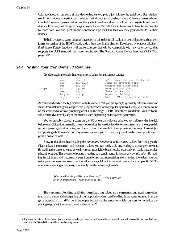
Consider again the code that returns some value for a given pot setting:
mov cx, -1 ;We’re going to count backwardsmov dx, 201h ;Point at joystick port.out dx, al ;Trigger the timer chip.
CntLp: in al, dx ;Read joystick port.test al, 1 ;Check pot #0 input.loopne CntLp ;Repeat while high.neg cx ;Convert CX to a positive value.
As mentioned earlier, the big problem with this code is that you are going to get wildly different ranges ofvalues from different game adapter cards, input devices, and computer systems. Clearly you cannot counton the code above always producing a value in the range 0..180h under these conditions. Your softwarewill need to dynamically adjust the values it uses depending on the system parameters.
You’ve probably played a game on the PC where the software asks you to
calibrate
the joystickbefore use. Calibration generally consists of moving the joystick handle to one corner (e.g., the upper-leftcorner), pressing a button or key and them moving the handle to the opposite corner (e.g., lower-right)and pressing a button again. Some systems even want you to move the joystick to the center position andpress a button as well.
Software that does this is reading the
minimum, maximum,
and
centered
values from the joystick.Given at least the minimum and maximum values, you can easily scale any reading to any range you want.By reading the centered value as well, you can get slightly better results, especially on really inexpensive(cheap) joysticks. This process of scaling a reading to a certain range is known as
normalization
. By read-ing the minimum and maximum values from the user and normalizing every reading thereafter, you canwrite your programs assuming that the values always fall within a certain range, for example, 0..255. Tonormalize a reading is very easy, you simply use the following formula:
The
MaximumReading
and
MinimumReading
values are the minimum and maximum valuesread from the user at the beginning of your application.
CurrentReading
is the value just read from thegame adapter.
NormalValue
is the upper bounds on the range to which you want to normalize thereading (e.g., 255), the lower bound is always zero
4
.
4. If you want a different lower bound, just add whatever value you want fro the lowest value to the result. You will also need to subtract this lowerbound from the NormalValue variable in the above equation.
CurrentReading MinimumReading–( )MaximumReading MinimumReading–( )
------------------------------------------------------------------------------------------------------------- NormalValue×

The Game Adapter
Page 1261
To get better results, especially when using a joystick, you should obtain three readings during thecalibration phase for each pot – a minimum value, a maximum value, and a centered value. To normalizea reading when you’ve got these three values, you would use one of the following formulae:
If the current reading is in the range minimum..center, use this formula:
If the current reading is in the range center..maximum, use this formula:
A large number of games on the market today jump through all kinds of hoops trying to coerce joy-stick readings into a reasonable range. It is surprising how few of them use that simple formula above.Some game designers might argue that the formulae above are overly complex and they are writing highperformance games. This is nonsense. It takes two orders of magnitude more time to wait for the joystickto time out than it does to compute the above equations. So use them and make your programs easier towrite.
Although normalizing your pot readings takes so little time it is always worthwhile, reading the ana-log inputs is a very expensive operation in terms of CPU cycles. Since the timer circuit produces relativelyfixed time delays for a given resistance, you will waste even more CPU cycles on a fast machine than youdo on a slow machine (although reading the pot takes about the same amount of
real
time on anymachine). One sure fire way to waste a lot of time is to read several pots one at a time; for example, whenreading pots zero and one to get a joystick reading, read pot zero first and then read pot one afterwards. Itturns out that you can easily read both pots in parallel. By doing so, you can speed up reading the joystickby a factor of two. Consider the following code:
mov cx, 1000h ;Max times through loopmov si, 0 ;We’ll put readings in SI andmov di, si ; di.mov ax, si ;Set AH to zero.mov dx, 201h ;Point at joystick port.out dx, al ;Trigger the timer chip.
CntLp: in al, dx ;Read joystick port.and al, 11b ;Strip unwanted bits.jz Doneshr ax, 1 ;Put pot 0 value into carry.adc si, 0 ;Bump pot 0 value if still active.add di, ax ;Bump pot 1 value if pot 1 active.loop CntLp ;Repeat while high.and si, 0FFFh ;If time-out, force the register(s)and di, 0FFFh ; containing 1000h to zero.
Done:
This code reads both pot zero and pot one at the same time. It works by looping while either pot isactive
5
. Each time through the loop, this code adds the pots’ bit values to separate register that accumula-tor the result. When this loop terminates,
si
and
di
contain the readings for both pots zero and one.
Although this particular loop contains more instructions than the previous loop, it still takes the sameamount of time to execute. Remember, the output pulses on the 558 timer determine how long this codetakes to execute, the number of instructions in the loop contribute very little to the execution time. How-ever, the time this loop takes to execute one iteration of the loop does effect the
resolution
of this joystickread routine. The faster the loop executes, the more iterations the loop will run during the same timingperiod and the finer will be the measurement. Generally, though, the resolution of the above code is muchgreater than the accuracy of the electronics and game input device, so this isn’t much of a concern.
5. This code provides a time-out feature in the event there is no game adapter installed. In such an event this code forces the readings to zero.
Current Center–( )Center Minimum–( ) 2×
----------------------------------------------------------------- NormalValue×
Current Center–( )Maximum Center–( ) 2×
------------------------------------------------------------------ NormalValueNormalValue
2------------------------------------+×
Chapter 24
Page 1262
The code above demonstrates how to read two pots. It is very easy to extend this code to read threeor four pots. An example of such a routine appears in the section on the SGDI device driver for the stan-dard game adapter card.
The other game device input, the switches, would seem to be simple in comparison to the potentiom-eter inputs. As usual, things are not as easy as they would seem at first glance. The switch inputs havesome problems of their own.
The first issue is keybounce. The switches on a typical joystick are probably an order of magnitudeworse than the keys on the cheapest keyboard. Keybounce, and lots of it, is a fact you’re going to have todeal with when reading joystick switches. In general, you shouldn’t read the joystick switches more oftenthan once every 10 msec. Many games read the switches on the 55 msec timer interrupt. For example, sup-pose your timer interrupt reads the switches and stores the result in a memory variable. The main applica-tion, when wanting to fire a weapon, checks the variable. If it’s set, the main program clears the variableand fires the weapon. Fifty-five milliseconds later, the timer sets the button variable again and the mainprogram will fire again the next time it checks the variable. Such a scheme will totally eliminate the prob-lems with keybounce.
The technique above solves another problem with the switches: keeping track of when the buttonfirst goes down. Remember, when you read the switches, the bits that come back tell you that the switch iscurrently down. It does not tell you that the button was just pressed. You have to keep track of this your-self. One easy way to detect when a user first presses a button is to save the previous switch reading andcompare it against the current reading. If they are different and the current reading indicates a switchdepression, then this is a new switch down.
24.5 The Standard Game Device Interface (SGDI)
The Standard Game Device Interface (SGDI) is a specification for an int 15h service that lets you readan arbitrary number of pots and joysticks. Writing SGDI compliant applications is easy and helps makeyour software compatible with any game device which provides SGDI compliance. By writing your appli-cations to use the SGDI API you can ensure that your applications will work with future devices that pro-vide extended SGDI capability. To understand the power and extensibility of the SGDI, you need to take alook at the
application programmer’s interface
(API) for the SGDI.
24.5.1 Application Programmer’s Interface (API)
The SGDI interface extends the PC’s joystick BIOS int 15h API. You make SGDI calls by loading the80x86
ah
register with 84h and
dx
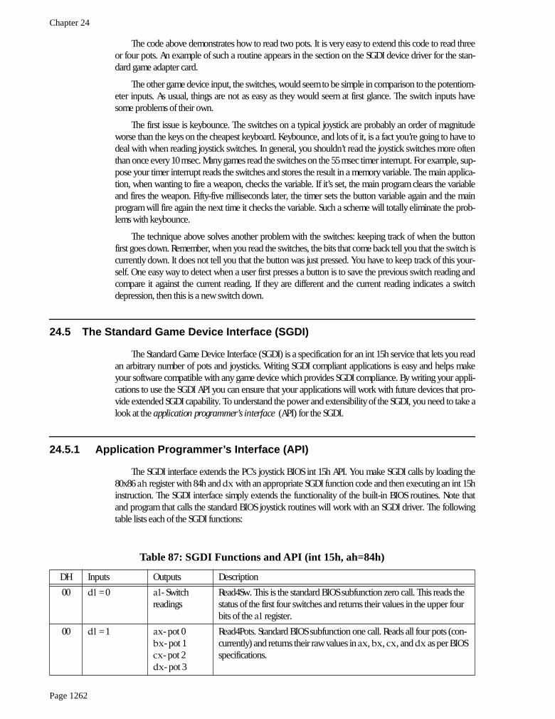
with an appropriate SGDI function code and then executing an int 15hinstruction. The SGDI interface simply extends the functionality of the built-in BIOS routines. Note thatand program that calls the standard BIOS joystick routines will work with an SGDI driver. The followingtable lists each of the SGDI functions:
Table 87: SGDI Functions and API (int 15h, ah=84h)
DH Inputs Outputs Description
00
dl
= 0
al
- Switch readings
Read4Sw. This is the standard BIOS subfunction zero call. This reads the status of the first four switches and returns their values in the upper four bits of the
al
register.
00
dl
= 1
ax
- pot 0
bx
- pot 1
cx
- pot 2
dx
- pot 3
Read4Pots. Standard BIOS subfunction one call. Reads all four pots (con-currently) and returns their raw values in
ax
,
bx
,
cx
, and
dx
as per BIOS specifications.
The Game Adapter
Page 1263
24.5.2 Read4Sw
Inputs:
ah
= 84h,
dx
= 0
This is the standard BIOS read switches call. It returns the status switches zero through three on thejoystick in the upper four bits of the
al
register. Bit four corresponds to switch zero, bit five to switch one,bit six to switch two, and bit seven to switch three. One zero in each bit position denotes a depressedswitch, a one bit corresponds to a switch in the up position. This call is provided for compatibility with theexisting BIOS joystick routines. To read the joystick switches you should use the
Read16Sw
calldescribed later in this document.
24.5.3 Read4Pots:
Inputs:
ah
= 84h,
dx
= 1
This is the standard BIOS read pots call. It reads the four pots on the standard game adapter card andreturns their readings in the
ax
(x axis/pot 0),
bx
(y axis/pot 1),
cx
(pot 2), and
dx
(pot 3) registers.These are
raw, uncalibrated
, pot readings whose values will differ from machine to machine and varydepending upon the game I/O card in use. This call is provided for compatibility with the existing BIOS
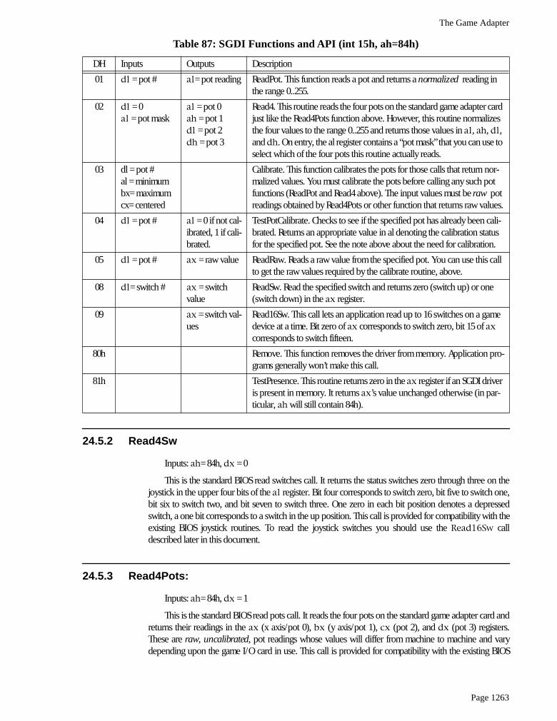
01
dl
= pot #
al
= pot reading ReadPot. This function reads a pot and returns a
normalized
reading in the range 0..255.
02
dl
= 0
al
= pot mask
al
= pot 0
ah
= pot 1
dl
= pot 2
dh
= pot 3
Read4. This routine reads the four pots on the standard game adapter card just like the Read4Pots function above. However, this routine normalizes the four values to the range 0..255 and returns those values in
al
,
ah
,
dl
, and
dh
. On entry, the al register contains a “pot mask” that you can use to select which of the four pots this routine actually reads.
03 dl = pot #al = minimumbx= maximumcx= centered
Calibrate. This function calibrates the pots for those calls that return nor-malized values. You must calibrate the pots before calling any such pot functions (ReadPot and Read4 above). The input values must be
raw
pot readings obtained by Read4Pots or other function that returns raw values.
04
dl
= pot #
al
= 0 if not cal-ibrated, 1 if cali-brated.
TestPotCalibrate. Checks to see if the specified pot has already been cali-brated. Returns an appropriate value in al denoting the calibration status for the specified pot. See the note above about the need for calibration.
05
dl
= pot #
ax
= raw value ReadRaw. Reads a raw value from the specified pot. You can use this call to get the raw values required by the calibrate routine, above.
08
dl
= switch #
ax
= switch value
ReadSw. Read the specified switch and returns zero (switch up) or one (switch down) in the
ax
register.
09
ax
= switch val-ues
Read16Sw. This call lets an application read up to 16 switches on a game device at a time. Bit zero of
ax
corresponds to switch zero, bit 15 of ax corresponds to switch fifteen.
80h Remove. This function removes the driver from memory. Application pro-grams generally won’t make this call.
81h TestPresence. This routine returns zero in the ax register if an SGDI driver is present in memory. It returns ax’s value unchanged otherwise (in par-ticular, ah will still contain 84h).
Table 87: SGDI Functions and API (int 15h, ah=84h)
DH Inputs Outputs Description
Chapter 24
Page 1264
joystick routines. To read the pots you should use the ReadPot, Read4, or ReadRaw routines describedin the next several sections.
24.5.4 ReadPot
Inputs: ah=84h, dh=1, dl=Pot number.
This reads the specified pot and returns a normalized pot value in the range 0..255 in the al register.This routine also sets ah to zero. Although the SGDI standard provides for up to 255 different pots, mostadapters only support pots zero, one, two, and three. If you attempt to read any nonsupported pot thisfunction returns zero in ax. Since the values are normalized, this call returns comparable values for agiven game control setting regardless of machine, clock frequency, or game I/O card in use. For example,a reading of 128 corresponds (roughly) to the center setting on almost any machine. To properly producenormalized results, you must calibrate a given pot before making this call. See the CalibratePot routinefor more details.
24.5.5 Read4:
Inputs: ah = 84h, al = pot mask, dx=0200h
This routine reads the four pots on the game adapter card, just like the BIOS call (Read4Pots).However, it returns normalized values in al (x axis/pot 0), ah (y axis/pot 1), dl (pot 2), and dh (pot 3).Since this routine returns normalized values between zero and 255, you must calibrate the pots before call-ing this code. The al register contains a “pot mask” value. The L.O. four bits of al determine if this routinewill actually read each pot. If bit zero, one, two, or three is one, then this function will read the corre-sponding pot; if the bits are zero, this routine will not read the corresponding pot and will return zero inthe corresponding register.
24.5.6 CalibratePot
Inputs: ah=84h, dh=3, dl=pot #, al=minimum value, bx=maximum value, cx=centered value.
Before you attempt to read a pot with the ReadPot or Read4 routines, you need to calibrate thatpot. If you read a pot without first calibrating it, the SGDI driver will return only zero for that pot reading.To calibrate a pot you will need to read raw values for the pot in a minimum position, maximum position,and a centered position6. These must be raw pot readings. Use readings obtained by the Read4Pots rou-tine. In theory, you need only calibrate a pot once after loading the SGDI driver. However, temperaturefluctuations and analog circuitry drift may decalibrate a pot after considerable use. Therefore, you shouldrecalibrate the pots you intend to read each time the user runs your application. Furthermore, you shouldgive the user the option of recalibrating the pots at any time within your program.
24.5.7 TestPotCalibration
Inputs: ah= 84h, dh=4 , dl = pot #.
This routine returns zero or one in ax denoting not calibrated or calibrated, respectively. You canuse the call to see if the pots you intend to use have already been calibrated and you can skip the calibra-tion phase. Please, however, note the comments about drift in the previous paragraph.
6. Many programmers compute the centered value as the arithmetic mean of the minimum and maximum values.

The Game Adapter
Page 1265
24.5.8 ReadRaw
Inputs: ah = 84h, dh = 5, dl = pot #
Reads the specified pot and returns a raw (not calibrated) value in ax. You can use this routine toobtain minimum, centered, and maximum values for use when calling the calibrate routine.
24.5.9 ReadSwitch
Inputs: ah= 84h, dh = 8, dl = switch #
This routine reads the specified switch and returns zero in ax if the switch is not depressed. It returnsone if the switch is depressed. Note that this value is opposite the bit settings the Read4Sw functionreturns.
If you attempt to read a switch number for an input that is not available on the current device, theSGDI driver will return zero (switch up). Standard game devices only support switches zero through threeand most joysticks only provide two switches. Therefore, unless you are willing to tie your application to aspecific device, you shouldn’t use any switches other than zero or one.
24.5.10 Read16Sw
Inputs: ah = 84h, dh = 9
This SGDI routine reads up to sixteen switches with a single call. It returns a bit vector in the ax reg-ister with bit 0 corresponding to switch zero, bit one corresponding to switch one, etc. Ones denote switchdepressed and zeros denote switches not depressed. Since the standard game adapter only supports fourswitches, only bits zero through three of al contain meaningful data (for those devices). All other bits willalways contain zero. SGDI drivers for the CH Product’s Flightstick Pro and Thrustmaster joysticks willreturn bits for the entire set of switches available on those devices.
24.5.11 Remove
Inputs: ah= 84h, dh= 80h
This call will attempt to remove the SGDI driver from memory. Generally, only the SGDI.EXE codeitself would invoke this routine. You should use the TestPresence routine (described next) to see if thedriver was actually removed from memory by this call.
24.5.12 TestPresence
Inputs: ah=84h, dh=81h
If an SGDI driver is present in memory, this routine return ax=0 and a pointer to an identificationstring in es:bx. If an SGDI driver is not present, this call will return ax unchanged.
24.5.13 An SGDI Driver for the Standard Game Adapter Card
If you write your program to make SGDI calls, you will discover that the TestPresence call willprobably return “not present” when your program searches for a resident SGDI driver in memory. This isbecause few manufacturers provide SGDI drivers at this point and even fewer standard game adapter

Chapter 24
Page 1266
companies ship any software at all with their products, much less an SGDI driver. Gee, what kind of stan-dard is this if no one uses it? Well, the purpose of this section is to rectify that problem.
The assembly code that appears at the end of this section provides a fully functional, public domain,SGDI driver for the standard game adapter card (the next section present an SGDI driver for the CH Prod-ucts’ Flightstick Pro). This allows you to write your application making only SGDI calls. By supplying theSGDI TSR with your product, your customers can use your software with all standard joysticks. Later, ifthey purchase a specialized device with its own SGDI driver, your software will automatically work withthat driver with no changes to your software7.
If you do not like the idea of having a user run a TSR before your application, you can always includethe following code within your program’s code space and activate it if the SGDI TestPresence calldetermines that no other SGDI driver is present in memory when you start your program.
Here’s the complete code for the standard game adapter SGDI driver:
.286page 58, 132name SGDItitle SGDI Driver for Standard Game Adapter Cardsubttl This Program is Public Domain Material.
; SGDI.EXE;; Usage:; SDGI;; This program loads a TSR which patches INT 15 so arbitrary game programs; can read the joystick in a portable fashion.;;; We need to load cseg in memory before any other segments!
cseg segment para public ‘code’cseg ends
; Initialization code, which we do not need except upon initial load,; goes in the following segment:
Initialize segment para public ‘INIT’Initialize ends
; UCR Standard Library routines which get dumped later on.
.xlistinclude stdlib.aincludelib stdlib.lib.list
sseg segment para stack ‘stack’sseg ends
zzzzzzseg segment para public ‘zzzzzzseg’zzzzzzseg ends
CSEG segment para public ‘CODE’assume cs:cseg, ds:nothing
wp equ <word ptr>byp equ <byte ptr>
Int15Vect dword 0
PSP word ?
7. Of course, your software may not take advantage of extra features, like additional switches and pots, but at least your software will support thestandard set of features on that device.
The Game Adapter
Page 1267
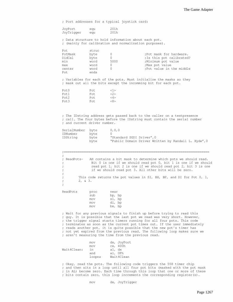
; Port addresses for a typical joystick card:
JoyPort equ 201hJoyTrigger equ 201h
; Data structure to hold information about each pot.; (mainly for calibration and normalization purposes).
Pot strucPotMask byte 0 ;Pot mask for hardware.DidCal byte 0 ;Is this pot calibrated?min word 5000 ;Minimum pot valuemax word 0 ;Max pot valuecenter word 0 ;Pot value in the middlePot ends
; Variables for each of the pots. Must initialize the masks so they; mask out all the bits except the incomming bit for each pot.
Pot0 Pot <1>Pot1 Pot <2>Pot2 Pot <4>Pot3 Pot <8>
; The IDstring address gets passed back to the caller on a testpresence; call. The four bytes before the IDstring must contain the serial number; and current driver number.
SerialNumber byte 0,0,0IDNumber byte 0IDString byte “Standard SGDI Driver”,0
byte “Public Domain Driver Written by Randall L. Hyde”,0
;============================================================================;; ReadPots- AH contains a bit mask to determine which pots we should read.; Bit 0 is one if we should read pot 0, bit 1 is one if we should; read pot 1, bit 2 is one if we should read pot 2, bit 3 is one; if we should read pot 3. All other bits will be zero.;; This code returns the pot values in SI, BX, BP, and DI for Pot 0, 1,; 2, & 3.;
ReadPots proc nearsub bp, bpmov si, bpmov di, bpmov bx, bp
; Wait for any previous signals to finish up before trying to read this; guy. It is possible that the last pot we read was very short. However,; the trigger signal starts timers running for all four pots. This code; terminates as soon as the current pot times out. If the user immediately; reads another pot, it is quite possible that the new pot’s timer has; not yet expired from the previous read. The following loop makes sure we; aren’t measuring the time from the previous read.
mov dx, JoyPortmov cx, 400h
Wait4Clean: in al, dxand al, 0Fhloopnz Wait4Clean
; Okay, read the pots. The following code triggers the 558 timer chip; and then sits in a loop until all four pot bits (masked with the pot mask; in AL) become zero. Each time through this loop that one or more of these; bits contain zero, this loop increments the corresponding register(s).
mov dx, JoyTrigger
Chapter 24
Page 1268
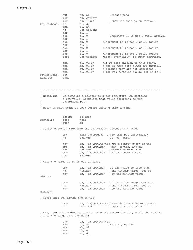
out dx, al ;Trigger potsmov dx, JoyPortmov cx, 1000h ;Don’t let this go on forever.
PotReadLoop: in al, dxand al, ahjz PotReadDoneshr al, 1adc si, 0 ;Increment SI if pot 0 still active.shr al, 1adc bx, 0 ;Increment BX if pot 1 still active.shr al, 1adc bp, 0 ;Increment BP if pot 2 still active.shr al, 1adc di, 0 ;Increment DI if pot 3 still active.loop PotReadLoop ;Stop, eventually, if funny hardware.
and si, 0FFFh ;If we drop through to this point,and bx, 0FFFh ; one or more pots timed out (usuallyand bp, 0FFFh ; because they are not connected).and di, 0FFFh ; The reg contains 4000h, set it to 0.
PotReadDone: retReadPots endp
;----------------------------------------------------------------------------;; Normalize- BX contains a pointer to a pot structure, AX contains; a pot value. Normalize that value according to the; calibrated pot.;; Note: DS must point at cseg before calling this routine.
assume ds:csegNormalize proc near
push cx
; Sanity check to make sure the calibration process went okay.
cmp [bx].Pot.DidCal, 0 ;Is this pot calibrated?je BadNorm ;If not, quit.
mov dx, [bx].Pot.Center ;Do a sanity check on thecmp dx, [bx].Pot.Min ; min, center, and maxjbe BadNorm ; values to make surecmp dx, [bx].Pot.Max ; min < center < max.jae BadNorm
; Clip the value if it is out of range.
cmp ax, [bx].Pot.Min ;If the value is less thanja MinOkay ; the minimum value, set itmov ax, [bx].Pot.Min ; to the minimum value.
MinOkay:
cmp ax, [bx].Pot.Max ;If the value is greater thanjb MaxOkay ; the maximum value, set itmov ax, [bx].Pot.Max ; to the maximum value.
MaxOkay:
; Scale this guy around the center:
cmp ax, [bx].Pot.Center ;See if less than or greaterjb Lower128 ; than centered value.
; Okay, current reading is greater than the centered value, scale the reading; into the range 128..255 here:
sub ax, [bx].Pot.Centermov dl, ah ;Multiply by 128mov ah, almov dh, 0mov al, dh
The Game Adapter
Page 1269
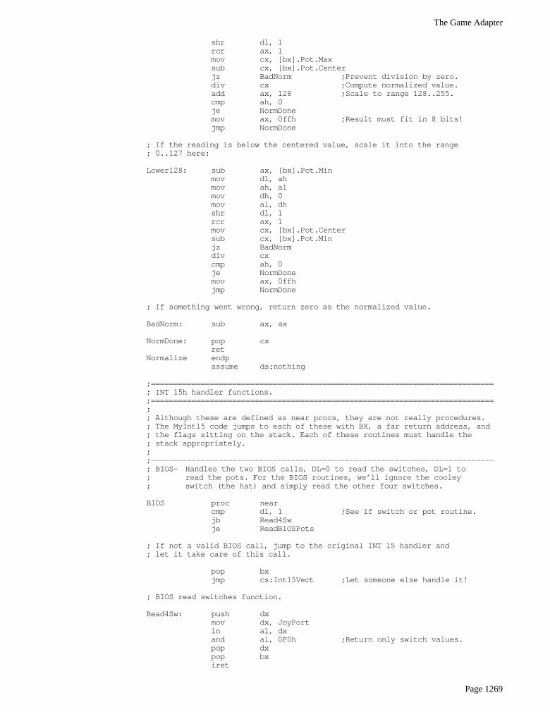
shr dl, 1rcr ax, 1mov cx, [bx].Pot.Maxsub cx, [bx].Pot.Centerjz BadNorm ;Prevent division by zero.div cx ;Compute normalized value.add ax, 128 ;Scale to range 128..255.cmp ah, 0je NormDonemov ax, 0ffh ;Result must fit in 8 bits!jmp NormDone
; If the reading is below the centered value, scale it into the range; 0..127 here:
Lower128: sub ax, [bx].Pot.Minmov dl, ahmov ah, almov dh, 0mov al, dhshr dl, 1rcr ax, 1mov cx, [bx].Pot.Centersub cx, [bx].Pot.Minjz BadNormdiv cxcmp ah, 0je NormDonemov ax, 0ffhjmp NormDone
; If something went wrong, return zero as the normalized value.
BadNorm: sub ax, ax
NormDone: pop cxret
Normalize endpassume ds:nothing
;============================================================================; INT 15h handler functions.;============================================================================;; Although these are defined as near procs, they are not really procedures.; The MyInt15 code jumps to each of these with BX, a far return address, and; the flags sitting on the stack. Each of these routines must handle the; stack appropriately.;;----------------------------------------------------------------------------; BIOS- Handles the two BIOS calls, DL=0 to read the switches, DL=1 to; read the pots. For the BIOS routines, we’ll ignore the cooley; switch (the hat) and simply read the other four switches.
BIOS proc nearcmp dl, 1 ;See if switch or pot routine.jb Read4Swje ReadBIOSPots
; If not a valid BIOS call, jump to the original INT 15 handler and; let it take care of this call.
pop bxjmp cs:Int15Vect ;Let someone else handle it!
; BIOS read switches function.
Read4Sw: push dxmov dx, JoyPortin al, dxand al, 0F0h ;Return only switch values.pop dxpop bxiret
Chapter 24
Page 1270
; BIOS read pots function.
ReadBIOSPots: pop bx ;Return a value in BX!push sipush dipush bpmov ah, 0Fh ;Read all four pots.call ReadPotsmov ax, simov cx, bp ;BX already contains pot 1 reading.mov dx, dipop bppop dipop siiret
BIOS endp
;----------------------------------------------------------------------------;; ReadPot- On entry, DL contains a pot number to read.; Read and normalize that pot and return the result in AL.
assume ds:csegReadPot proc near;;;;;;;;;; push bx ;Already on stack.
push dspush cxpush dxpush sipush dipush bp
mov bx, csegmov ds, bx
; If dl = 0, read and normalize the value for pot 0, if not, try some; other pot.
cmp dl, 0jne Try1mov ah, Pot0.PotMask ;Get bit for this pot.call ReadPots ;Read pot 0.lea bx, Pot0 ;Pointer to pot data.mov ax, si ;Get pot 0 reading.call Normalize ;Normalize to 0..FFh.jmp GotPot ;Return to caller.
; Test for DL=1 here (read and normalize pot 1).
Try1: cmp dl, 1jne Try2mov ah, Pot1.PotMaskcall ReadPotsmov ax, bxlea bx, Pot1call Normalizejmp GotPot
; Test for DL=2 here (read and normalize pot 2).
Try2: cmp dl, 2jne Try3mov ah, Pot2.PotMaskcall ReadPotslea bx, Pot2mov ax, bpcall Normalizejmp GotPot
; Test for DL=3 here (read and normalize pot 3).
Try3: cmp dl, 3jne BadPot
The Game Adapter
Page 1271
mov ah, Pot3.PotMaskcall ReadPotslea bx, Pot3mov ax, dicall Normalizejmp GotPot
; Bad value in DL if we drop to this point. The standard game card; only supports four pots.
BadPot: sub ax, ax ;Pot not available, return zero.GotPot: pop bp
pop dipop sipop dxpop cxpop dspop bxiret
ReadPot endpassume ds:nothing
;----------------------------------------------------------------------------;; ReadRaw- On entry, DL contains a pot number to read.; Read that pot and return the unnormalized result in AX.
assume ds:csegReadRaw proc near;;;;;;;;;; push bx ;Already on stack.
push dspush cxpush dxpush sipush dipush bp
mov bx, csegmov ds, bx
; This code is almost identical to the ReadPot code. The only difference; is that we don’t bother normalizing the result and (of course) we return; the value in AX rather than AL.
cmp dl, 0jne Try1mov ah, Pot0.PotMaskcall ReadPotsmov ax, sijmp GotPot
Try1: cmp dl, 1jne Try2mov ah, Pot1.PotMaskcall ReadPotsmov ax, bxjmp GotPot
Try2: cmp dl, 2jne Try3mov ah, Pot2.PotMaskcall ReadPotsmov ax, bpjmp GotPot
Try3: cmp dl, 3jne BadPotmov ah, Pot3.PotMaskcall ReadPotsmov ax, dijmp GotPot
BadPot: sub ax, ax ;Pot not available, return zero.
Chapter 24
Page 1272
GotPot: pop bppop dipop sipop dxpop cxpop dspop bxiret
ReadRaw endpassume ds:nothing
;----------------------------------------------------------------------------; Read4Pots- Reads pots zero, one, two, and three returning their; values in AL, AH, DL, and DH.;; On entry, AL contains the pot mask to select which pots; we should read (bit 0=1 for pot 0, bit 1=1 for pot 1, etc).
Read4Pots proc near;;;;;;;;;;; push bx ;Already on stack
push dspush cxpush sipush dipush bp
mov dx, csegmov ds, dx
mov ah, alcall ReadPots
push bx ;Save pot 1 reading.mov ax, si ;Get pot 0 reading.lea bx, Pot0 ;Point bx at pot0 vars.call Normalize ;Normalize.mov cl, al ;Save for later.
pop ax ;Retreive pot 1 reading.lea bx, Pot1call Normalizemov ch, al ;Save normalized value.
mov ax, bplea bx, Pot2call Normalizemov dl, al ;Pot 2 value.
mov ax, dilea bx, Pot3call Normalizemov dh, al ;Pot 3 value.mov ax, cx ;Pots 0 and 1.
pop bppop dipop sipop cxpop dspop bxiret
Read4Pots endp
;----------------------------------------------------------------------------; CalPot- Calibrate the pot specified by DL. On entry, AL contains; the minimum pot value (it better be less than 256!), BX; contains the maximum pot value, and CX contains the centered; pot value.
assume ds:cseg
The Game Adapter
Page 1273
CalPot proc nearpop bx ;Retrieve maximum valuepush dspush simov si, csegmov ds, si
; Sanity check on parameters, sort them in ascending order:
mov ah, 0cmp bx, cx ;Make sure center < maxja GoodMaxxchg bx, cx
GoodMax: cmp ax, cx ;Make sure min < center.jb GoodMin ; (note: may make center<max).xchg ax, cx
GoodMin: cmp cx, bx ;Again, be sure center < max.jb GoodCenterxchg cx, bx
GoodCenter:
; Okay, figure out who were supposed to calibrate:
lea si, Pot0cmp dl, 1jb DoCal ;Branch if this is pot 0lea si, Pot1je DoCal ;Branch if this is pot 1lea si, Pot2cmp dl, 3jb DoCal ;Branch if this is pot 2jne CalDone ;Branch if not pot 3lea si, Pot3
DoCal: mov [si].Pot.min, ax ;Store away the minimum,mov [si].Pot.max, bx ; maximum, andmov [si].Pot.center, cx ; centered values.mov [si].Pot.DidCal, 1 ;Note we’ve cal’d this pot.
CalDone: pop sipop dsiret
CalPot endpassume ds:nothing
;----------------------------------------------------------------------------; TestCal- Just checks to see if the pot specified by DL has already; been calibrated.
assume ds:csegTestCal proc near;;;;;;;; push bx ;Already on stack
push dsmov bx, csegmov ds, bx
sub ax, ax ;Assume no calibration (also zeros AH)lea bx, Pot0 ;Get the address of the specifiedcmp dl, 1 ; pot’s data structure into thejb GetCal ; BX register.lea bx, Pot1je GetCallea bx, Pot2cmp dl, 3jb GetCaljne BadCallea bx, Pot3
GetCal: mov al, [bx].Pot.DidCalBadCal: pop ds
pop bxiret
TestCal endp
Chapter 24
Page 1274
assume ds:nothing
;----------------------------------------------------------------------------;; ReadSw- Reads the switch whose switch number appears in DL.
ReadSw proc near;;;;;;; push bx ;Already on stack
push cx
sub ax, ax ;Assume no such switch.cmp dl, 3 ;Return if the switch number isja NotDown ; greater than three.
mov cl, dl ;Save switch to read.add cl, 4 ;Move from position four down to zero.mov dx, JoyPortin al, dx ;Read the switches.shr al, cl ;Move desired switch bit into bit 0.xor al, 1 ;Invert so sw down=1.and ax, 1 ;Remove other junk bits.
NotDown: pop cxpop bxiret
ReadSw endp
;----------------------------------------------------------------------------;; Read16Sw- Reads all four switches and returns their values in AX.
Read16Sw proc near;;;;;;;; push bx ;Already on stack
mov dx, JoyPortin al, dxshr al, 4xor al, 0Fh ;Invert all switches.and ax, 0Fh ;Set other bits to zero.pop bxiret
Read16Sw endp
;****************************************************************************;; MyInt15- Patch for the BIOS INT 15 routine to control reading the; joystick.
MyInt15 proc farpush bxcmp ah, 84h ;Joystick code?je DoJoystick
OtherInt15: pop bxjmp cs:Int15Vect
DoJoystick: mov bh, 0mov bl, dhcmp bl, 80hjae VendorCallscmp bx, JmpSizejae OtherInt15shl bx, 1jmp wp cs:jmptable[bx]
jmptable word BIOSword ReadPot, Read4Pots, CalPot, TestCalword ReadRaw, OtherInt15, OtherInt15word ReadSw, Read16Sw
JmpSize = ($-jmptable)/2
; Handle vendor specific calls here.
The Game Adapter
Page 1275
VendorCalls: je RemoveDrivercmp bl, 81hje TestPresencepop bxjmp cs:Int15Vect
; TestPresence- Returns zero in AX and a pointer to the ID string in ES:BX
TestPresence: pop bx ;Get old value off stack.sub ax, axmov bx, csegmov es, bxlea bx, IDStringiret
; RemoveDriver-If there are no other drivers loaded after this one in; memory, disconnect it and remove it from memory.
RemoveDriver:push dspush espush axpush dx
mov dx, csegmov ds, dx
; See if we’re the last routine patched into INT 15h
mov ax, 3515hint 21hcmp bx, offset MyInt15jne CantRemovemov bx, escmp bx, wp seg MyInt15jne CantRemove
mov ax, PSP ;Free the memory we’re inmov es, axpush esmov ax, es:[2ch] ;First, free env block.mov es, axmov ah, 49hint 21h
pop es ;Now free program space.mov ah, 49hint 21h
lds dx, Int15Vect ;Restore previous int vect.mov ax, 2515hint 21h
CantRemove: pop dxpop axpop espop dspop bxiret
MyInt15 endpcseg ends
Initialize segment para public ‘INIT’assume cs:Initialize, ds:cseg
Main procmov ax, cseg ;Get ptr to vars segmentmov es, axmov es:PSP, ds ;Save PSP value awaymov ds, ax
mov ax, zzzzzzseg

Chapter 24
Page 1276
mov es, axmov cx, 100hmeminit2
printbyte “ Standard Game Device Interface driver”,cr,lfbyte “ PC Compatible Game Adapter Cards”,cr,lfbyte “ Written by Randall Hyde”,cr,lfbyte cr,lfbyte cr,lfbyte “‘SGDI REMOVE’ removes the driver from memory”,cr,lfbyte lfbyte 0
mov ax, 1argv ;If no parameters, empty str.stricmplbyte “REMOVE”,0jne NoRmv
mov dh, 81h ;Remove opcode.mov ax, 84ffhint 15h ;See if we’re already loaded.test ax, ax ;Get a zero back?jz Installedprintbyte “SGDI driver is not present in memory, REMOVE “byte “command ignored.”,cr,lf,0mov ax, 4c01h;Exit to DOS.int 21h
Installed: mov ax, 8400hmov dh, 80h ;Remove callint 15hmov ax, 8400hmov dh, 81h ;TestPresence callint 15hcmp ax, 0je NotRemovedprintbyte “Successfully removed SGDI driver from memory.”byte cr,lf,0mov ax, 4c01h ;Exit to DOS.int 21h
NotRemoved: printbyte “SGDI driver is still present in memory.”,cr,lf,0mov ax, 4c01h ;Exit to DOS.int 21h
; Okay, Patch INT 15 and go TSR at this point.
NoRmv:mov ax, 3515hint 21hmov wp Int15Vect, bxmov wp Int15Vect+2, es
mov dx, csegmov ds, dxmov dx, offset MyInt15mov ax, 2515hint 21h
mov dx, csegmov ds, dxmov dx, seg Initializesub dx, ds:pspadd dx, 2mov ax, 3100h ;Do TSR
The Game Adapter
Page 1277
int 21hMain endp
Initialize ends
sseg segment para stack ‘stack’word 128 dup (0)
endstk word ?sseg ends
zzzzzzseg segment para public ‘zzzzzzseg’byte 16 dup (0)
zzzzzzseg endsend Main
The following program makes several different types of calls to an SGDI driver. You can use this codeto test out an SGDI TSR:
.xlistinclude stdlib.aincludelib stdlib.lib.list
cseg segment para public ‘code’assume cs:cseg, ds:nothing
MinVal0 word ?MinVal1 word ?MaxVal0 word ?MaxVal1 word ?
; Wait4Button-Waits until the user presses and releases a button.
Wait4Button proc nearpush axpush dxpush cx
W4BLp: mov ah, 84hmov dx, 900h ;Read the L.O. 16 buttons.int 15hcmp ax, 0 ;Any button down? If not, je W4BLp ; loop until this is so.
xor cx, cx ;Debouncing delay loop.Delay: loop Delay
W4nBLp: mov ah, 84h ;Now wait until the user releasesmov dx, 900h ; all buttonsint 15hcmp ax, 0jne W4nBLp
Delay2: loop Delay2
pop cxpop dxpop axret
Wait4Button endp
Main proc
printbyte “SGDI Test Program.”,cr,lf
Chapter 24
Page 1278
byte “Written by Randall Hyde”,cr,lf,lfbyte “Press any key to continue”,cr,lf,0
getc
mov ah, 84hmov dh, 4 ;Test presence call.int 15hcmp ax, 0 ;See if thereje MainLoop0printbyte “No SGDI driver present in memory.”,cr,lf,0jmp Quit
MainLoop0:printbyte “BIOS: “,0
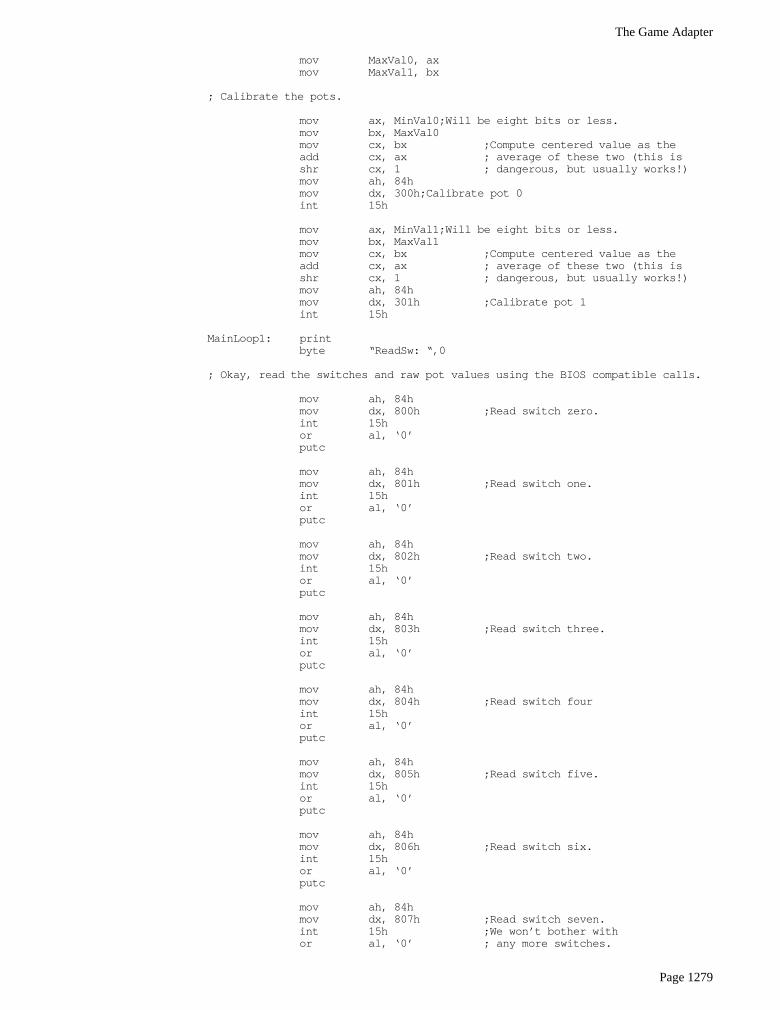
; Okay, read the switches and raw pot values using the BIOS compatible calls.
mov ah, 84hmov dx, 0 ;BIOS compat. read switches.int 15hputh ;Output switch values.mov al, ‘ ‘putc
mov ah, 84h ;BIOS compat. read pots.mov dx, 1int 15hputwmov al, ‘ ‘putcmov ax, bxputwmov al, ‘ ‘putcmov ax, cxputwmov al, ‘ ‘putcmov ax, dxputw
putcrmov ah, 1 ;Repeat until key press.int 16hje MainLoop0getc
; Read the minimum and maximum values for each pot from the user so we; can calibrate the pots.
printbyte cr,lf,lf,lfbyte “Move joystick to upper left corner and press “byte “any button.”,cr,lf,0
call Wait4Buttonmov ah, 84hmov dx, 1 ;Read Raw Valuesint 15hmov MinVal0, axmov MinVal1, bx
printbyte cr,lfbyte “Move the joystick to the lower right corner “byte “and press any button”,cr,lf,0
call Wait4Buttonmov ah, 84hmov dx, 1 ;Read Raw Valuesint 15h
The Game Adapter
Page 1279
mov MaxVal0, axmov MaxVal1, bx
; Calibrate the pots.
mov ax, MinVal0;Will be eight bits or less.mov bx, MaxVal0mov cx, bx ;Compute centered value as theadd cx, ax ; average of these two (this isshr cx, 1 ; dangerous, but usually works!)mov ah, 84hmov dx, 300h;Calibrate pot 0int 15h
mov ax, MinVal1;Will be eight bits or less.mov bx, MaxVal1mov cx, bx ;Compute centered value as theadd cx, ax ; average of these two (this isshr cx, 1 ; dangerous, but usually works!)mov ah, 84hmov dx, 301h ;Calibrate pot 1int 15h
MainLoop1: printbyte “ReadSw: “,0
; Okay, read the switches and raw pot values using the BIOS compatible calls.
mov ah, 84hmov dx, 800h ;Read switch zero.int 15hor al, ‘0’putc
mov ah, 84hmov dx, 801h ;Read switch one.int 15hor al, ‘0’putc
mov ah, 84hmov dx, 802h ;Read switch two.int 15hor al, ‘0’putc
mov ah, 84hmov dx, 803h ;Read switch three.int 15hor al, ‘0’putc
mov ah, 84hmov dx, 804h ;Read switch fourint 15hor al, ‘0’putc
mov ah, 84hmov dx, 805h ;Read switch five.int 15hor al, ‘0’putc
mov ah, 84hmov dx, 806h ;Read switch six.int 15hor al, ‘0’putc
mov ah, 84hmov dx, 807h ;Read switch seven.int 15h ;We won’t bother withor al, ‘0’ ; any more switches.

Chapter 24
Page 1280
putcmov al, ‘ ‘putc
mov ah, 84hmov dh, 9 ;Read all 16 switches.int 15hputw
printbyte “ Pots: “,0mov ax, 8403h ;Read joystick pots.mov dx, 200h ;Read four pots.int 15hputhmov al, ‘ ‘putcmov al, ahputhmov al, ‘ ‘putc
mov ah, 84hmov dx, 503h ;Raw read, pot 3.int 15hputw
putcrmov ah, 1 ;Repeat until key press.int 16hje MainLoop1getc
Quit: ExitPgm ;DOS macro to quit program.Main endp
cseg ends
sseg segment para stack ‘stack’stk byte 1024 dup (“stack “)sseg ends
zzzzzzseg segment para public ‘zzzzzz’LastBytes byte 16 dup (?)zzzzzzseg ends
end Main
24.6 An SGDI Driver for the CH Products’ Flight Stick Pro
The CH Product’s FlightStick Pro joystick is a good example of a specialized product for which theSGDI driver is a perfect solution. The FlightStick Pro provides three pots and five switches, the fifth switchbeing a special five-position cooley switch. Although the pots on the FlightStick Pro map to three of theanalog inputs on the standard game adapter card (pots zero, one, and three), there are insufficient digitalinputs to handle the eight inputs necessary for the FlightStick Pro’s four buttons and cooley switch.
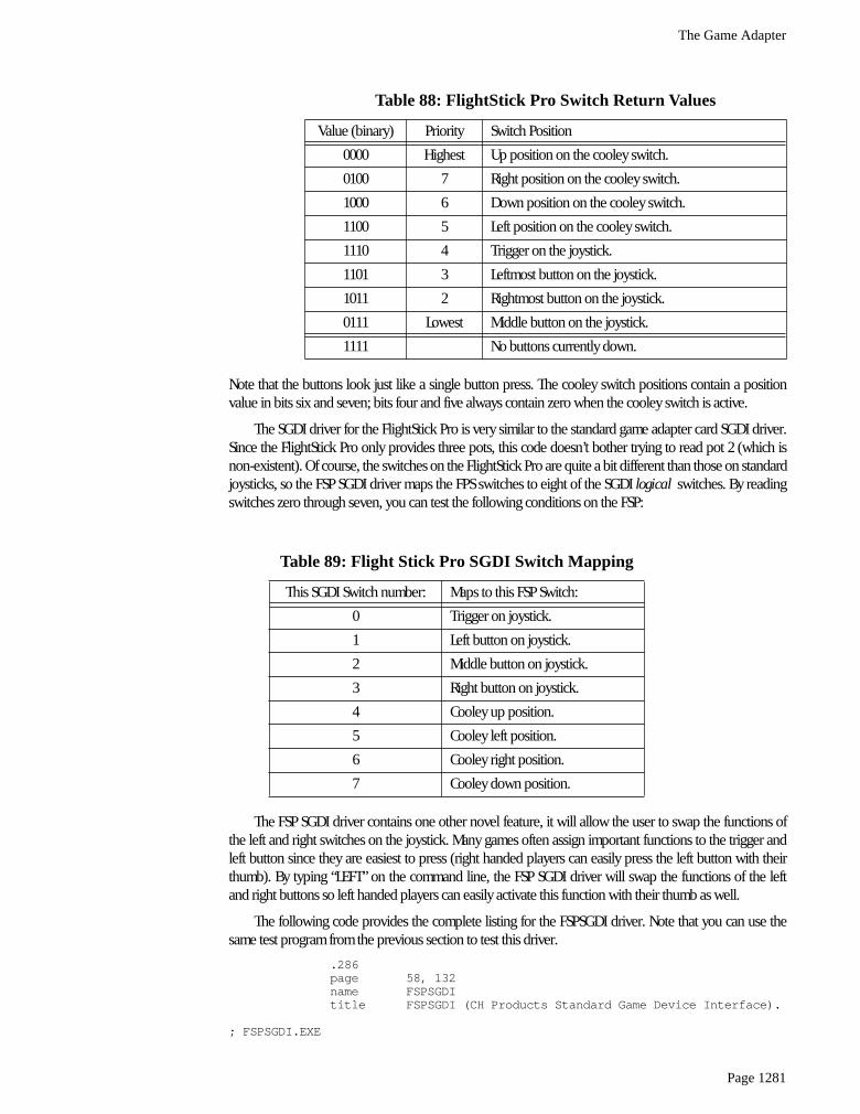
The FlightStick Pro (FSP) uses some electronic circuitry to map these eight switch positions to fourinput bits. To do so, they place one restriction on the use of the FSP switches – you can only press one ofthem at a time. If you hold down two or more switches at the same time, the FSP hardware selects one ofthe switches and reports that value; it ignores the other switches until you release the button. Since onlyone switch can be read at a time, the FSP hardware generates a four bit value that determines the currentstate of the switches. It returns these four bits as the switch values on the standard game adapter card. Thefollowing table lists the values for each of the switches:
The Game Adapter
Page 1281
Note that the buttons look just like a single button press. The cooley switch positions contain a positionvalue in bits six and seven; bits four and five always contain zero when the cooley switch is active.
The SGDI driver for the FlightStick Pro is very similar to the standard game adapter card SGDI driver.Since the FlightStick Pro only provides three pots, this code doesn’t bother trying to read pot 2 (which isnon-existent). Of course, the switches on the FlightStick Pro are quite a bit different than those on standardjoysticks, so the FSP SGDI driver maps the FPS switches to eight of the SGDI logical switches. By readingswitches zero through seven, you can test the following conditions on the FSP:
The FSP SGDI driver contains one other novel feature, it will allow the user to swap the functions ofthe left and right switches on the joystick. Many games often assign important functions to the trigger andleft button since they are easiest to press (right handed players can easily press the left button with theirthumb). By typing “LEFT” on the command line, the FSP SGDI driver will swap the functions of the leftand right buttons so left handed players can easily activate this function with their thumb as well.
The following code provides the complete listing for the FSPSGDI driver. Note that you can use thesame test program from the previous section to test this driver.
.286page 58, 132name FSPSGDItitle FSPSGDI (CH Products Standard Game Device Interface).
; FSPSGDI.EXE
Table 88: FlightStick Pro Switch Return Values
Value (binary) Priority Switch Position
0000 Highest Up position on the cooley switch.
0100 7 Right position on the cooley switch.
1000 6 Down position on the cooley switch.
1100 5 Left position on the cooley switch.
1110 4 Trigger on the joystick.
1101 3 Leftmost button on the joystick.
1011 2 Rightmost button on the joystick.
0111 Lowest Middle button on the joystick.
1111 No buttons currently down.
Table 89: Flight Stick Pro SGDI Switch Mapping
This SGDI Switch number: Maps to this FSP Switch:
0 Trigger on joystick.
1 Left button on joystick.
2 Middle button on joystick.
3 Right button on joystick.
4 Cooley up position.
5 Cooley left position.
6 Cooley right position.
7 Cooley down position.
Chapter 24
Page 1282
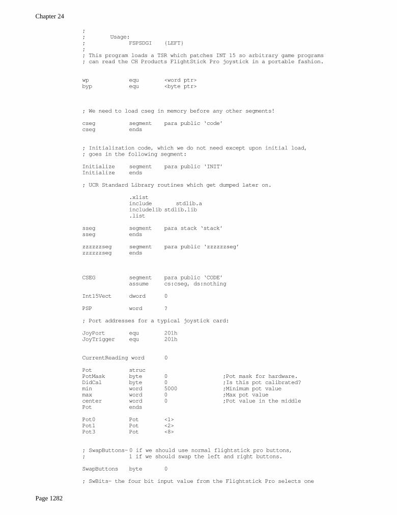
;; Usage:; FSPSDGI {LEFT};; This program loads a TSR which patches INT 15 so arbitrary game programs; can read the CH Products FlightStick Pro joystick in a portable fashion.
wp equ <word ptr>byp equ <byte ptr>
; We need to load cseg in memory before any other segments!
cseg segment para public ‘code’cseg ends
; Initialization code, which we do not need except upon initial load,; goes in the following segment:
Initialize segment para public ‘INIT’Initialize ends
; UCR Standard Library routines which get dumped later on.
.xlistinclude stdlib.aincludelib stdlib.lib.list
sseg segment para stack ‘stack’sseg ends
zzzzzzseg segment para public ‘zzzzzzseg’zzzzzzseg ends
CSEG segment para public ‘CODE’assume cs:cseg, ds:nothing
Int15Vect dword 0
PSP word ?
; Port addresses for a typical joystick card:
JoyPort equ 201hJoyTrigger equ 201h
CurrentReading word 0
Pot strucPotMask byte 0 ;Pot mask for hardware.DidCal byte 0 ;Is this pot calibrated?min word 5000 ;Minimum pot valuemax word 0 ;Max pot valuecenter word 0 ;Pot value in the middlePot ends
Pot0 Pot <1>Pot1 Pot <2>Pot3 Pot <8>
; SwapButtons-0 if we should use normal flightstick pro buttons,; 1 if we should swap the left and right buttons.
SwapButtons byte 0
; SwBits- the four bit input value from the Flightstick Pro selects one
The Game Adapter
Page 1283
; of the following bit patterns for a given switch position.
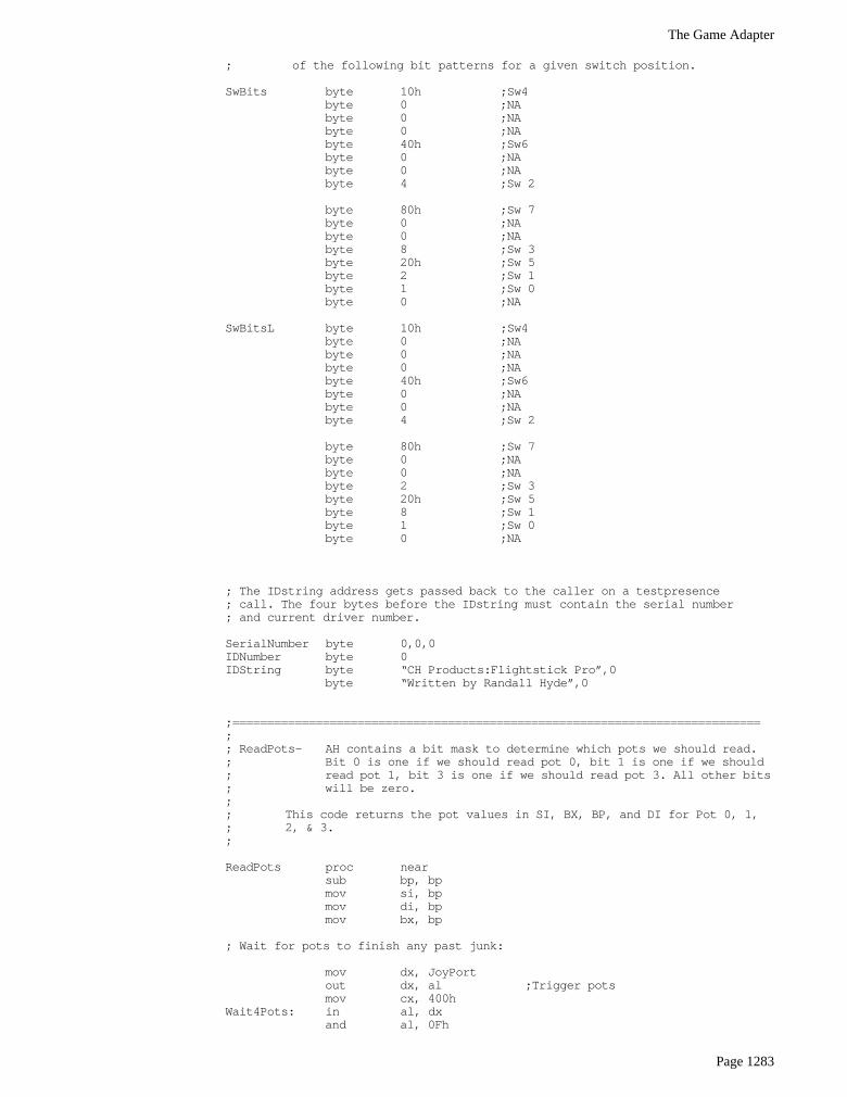
SwBits byte 10h ;Sw4byte 0 ;NAbyte 0 ;NAbyte 0 ;NAbyte 40h ;Sw6byte 0 ;NAbyte 0 ;NAbyte 4 ;Sw 2
byte 80h ;Sw 7byte 0 ;NAbyte 0 ;NAbyte 8 ;Sw 3byte 20h ;Sw 5byte 2 ;Sw 1byte 1 ;Sw 0byte 0 ;NA
SwBitsL byte 10h ;Sw4byte 0 ;NAbyte 0 ;NAbyte 0 ;NAbyte 40h ;Sw6byte 0 ;NAbyte 0 ;NAbyte 4 ;Sw 2
byte 80h ;Sw 7byte 0 ;NAbyte 0 ;NAbyte 2 ;Sw 3byte 20h ;Sw 5byte 8 ;Sw 1byte 1 ;Sw 0byte 0 ;NA
; The IDstring address gets passed back to the caller on a testpresence; call. The four bytes before the IDstring must contain the serial number; and current driver number.
SerialNumber byte 0,0,0IDNumber byte 0IDString byte “CH Products:Flightstick Pro”,0
byte “Written by Randall Hyde”,0
;============================================================================;; ReadPots- AH contains a bit mask to determine which pots we should read.; Bit 0 is one if we should read pot 0, bit 1 is one if we should; read pot 1, bit 3 is one if we should read pot 3. All other bits; will be zero.;; This code returns the pot values in SI, BX, BP, and DI for Pot 0, 1,; 2, & 3.;
ReadPots proc nearsub bp, bpmov si, bpmov di, bpmov bx, bp
; Wait for pots to finish any past junk:
mov dx, JoyPortout dx, al ;Trigger potsmov cx, 400h
Wait4Pots: in al, dxand al, 0Fh
Chapter 24
Page 1284
loopnz Wait4Pots
; Okay, read the pots:
mov dx, JoyTriggerout dx, al ;Trigger potsmov dx, JoyPortmov cx, 8000h ;Don’t let this go on forever.
PotReadLoop: in al, dxand al, ahjz PotReadDoneshr al, 1adc si, 0shr al, 1adc bp, 0shr al, 2adc di, 0loop PotReadLoop
PotReadDone:ret
ReadPots endp
;----------------------------------------------------------------------------;; Normalize- BX contains a pointer to a pot structure, AX contains; a pot value. Normalize that value according to the; calibrated pot.;; Note: DS must point at cseg before calling this routine.
assume ds:csegNormalize proc near
push cx
; Sanity check to make sure the calibration process went okay.
cmp [bx].Pot.DidCal, 0je BadNormmov dx, [bx].Pot.Centercmp dx, [bx].Pot.Minjbe BadNormcmp dx, [bx].Pot.Maxjae BadNorm
; Clip the value if it is out of range.
cmp ax, [bx].Pot.Minja MinOkaymov ax, [bx].Pot.Min
MinOkay:
cmp ax, [bx].Pot.Maxjb MaxOkaymov ax, [bx].Pot.Max
MaxOkay:
; Scale this guy around the center:
cmp ax, [bx].Pot.Centerjb Lower128
; Scale in the range 128..255 here:
sub ax, [bx].Pot.Centermov dl, ah ;Multiply by 128mov ah, almov dh, 0mov al, dhshr dl, 1rcr ax, 1mov cx, [bx].Pot.Maxsub cx, [bx].Pot.Centerjz BadNorm ;Prevent division by zero.
The Game Adapter
Page 1285
div cx ;Compute normalized value.add ax, 128 ;Scale to range 128..255.cmp ah, 0je NormDonemov ax, 0ffh ;Result must fit in 8 bits!jmp NormDone
; Scale in the range 0..127 here:
Lower128: sub ax, [bx].Pot.Minmov dl, ah ;Multiply by 128mov ah, almov dh, 0mov al, dhshr dl, 1rcr ax, 1mov cx, [bx].Pot.Centersub cx, [bx].Pot.Minjz BadNormdiv cx ;Compute normalized value.cmp ah, 0je NormDonemov ax, 0ffh ;Result must fit in 8 bits!jmp NormDone
BadNorm: sub ax, axNormDone: pop cx
retNormalize endp
assume ds:nothing
;============================================================================; INT 15h handler functions.;============================================================================;; Although these are defined as near procs, they are not really procedures.; The MyInt15 code jumps to each of these with BX, a far return address, and; the flags sitting on the stack. Each of these routines must handle the; stack appropriately.;;----------------------------------------------------------------------------; BIOS- Handles the two BIOS calls, DL=0 to read the switches, DL=1 to; read the pots. For the BIOS routines, we’ll ignore the cooley; switch (the hat) and simply read the other four switches.
BIOS proc nearcmp dl, 1 ;See if switch or pot routine.jb Read4Swje ReadBIOSPotspop bxjmp cs:Int15Vect ;Let someone else handle it!
Read4Sw: push dxmov dx, JoyPortin al, dxshr al, 4mov bl, almov bh, 0cmp cs:SwapButtons, 0je DoLeft2mov al, cs:SwBitsL[bx]jmp SBDone
DoLeft2: mov al, cs:SwBits[bx]SBDone: rol al, 4 ;Put Sw0..3 in upper bits and make
not al ; 0=switch down, just like game card.pop dxpop bxiret
ReadBIOSPots: pop bx ;Return a value in BX!push sipush dipush bp

Chapter 24
Page 1286
mov ah, 0bhcall ReadPotsmov ax, simov bx, bpmov dx, disub cx, cxpop bppop dipop siiret
BIOS endp
;----------------------------------------------------------------------------;; ReadPot- On entry, DL contains a pot number to read.; Read and normalize that pot and return the result in AL.
assume ds:csegReadPot proc near;;;;;;;;;; push bx ;Already on stack.
push dspush cxpush dxpush sipush dipush bp
mov bx, csegmov ds, bx
cmp dl, 0jne Try1mov ah, Pot0.PotMaskcall ReadPotslea bx, Pot0mov ax, sicall Normalizejmp GotPot
Try1: cmp dl, 1jne Try3mov ah, Pot1.PotMaskcall ReadPotslea bx, Pot1mov ax, bpcall Normalizejmp GotPot
Try3: cmp dl, 3jne BadPotmov ah, Pot3.PotMaskcall ReadPotslea bx, Pot3mov ax, dicall Normalizejmp GotPot
BadPot: sub ax, ax ;Question: Should we pass this on; or just return zero?
GotPot: pop bppop dipop sipop dxpop cxpop dspop bxiret
ReadPot endpassume ds:nothing
;----------------------------------------------------------------------------;
The Game Adapter
Page 1287
; ReadRaw- On entry, DL contains a pot number to read.; Read that pot and return the unnormalized result in AL.
assume ds:csegReadRaw proc near;;;;;;;;;; push bx ;Already on stack.
push dspush cxpush dxpush sipush dipush bp
mov bx, csegmov ds, bx
cmp dl, 0jne Try1mov ah, Pot0.PotMaskcall ReadPotsmov ax, sijmp GotPot
Try1: cmp dl, 1jne Try3mov ah, Pot1.PotMaskcall ReadPotsmov ax, bpjmp GotPot
Try3: cmp dl, 3jne BadPotmov ah, Pot3.PotMaskcall ReadPotsmov ax, dijmp GotPot
BadPot: sub ax, ax ;Just return zero.GotPot: pop bp
pop dipop sipop dxpop cxpop dspop bxiret
ReadRaw endpassume ds:nothing
;----------------------------------------------------------------------------; Read4Pots-Reads pots zero, one, two, and three returning their; values in AL, AH, DL, and DH. Since the flightstick; Pro doesn’t have a pot 2 installed, return zero for; that guy.
Read4Pots proc near;;;;;;;;;;; push bx ;Already on stack
push dspush cxpush sipush dipush bp
mov dx, csegmov ds, dx
mov ah, 0bh ;Read pots 0, 1, and 3.call ReadPots
mov ax, silea bx, Pot0call Normalizemov cl, al
Chapter 24
Page 1288
mov ax, bplea bx, Pot1call Normalizemov ch, al
mov ax, dilea bx, Pot3call Normalizemov dh, al ;Pot 3 value.mov ax, cx ;Pots 0 and 1.mov dl, 0 ;Pot 2 is non-existant.
pop bppop dipop sipop cxpop dspop bxiret
Read4Pots endp
;----------------------------------------------------------------------------; CalPot- Calibrate the pot specified by DL. On entry, AL contains; the minimum pot value (it better be less than 256!), BX; contains the maximum pot value, and CX contains the centered; pot value.
assume ds:csegCalPot proc near
pop bx ;Retrieve maximum valuepush dspush simov si, csegmov ds, si
; Sanity check on parameters, sort them in ascending order:
mov ah, 0cmp bx, cxja GoodMaxxchg bx, cx
GoodMax: cmp ax, cxjb GoodMinxchg ax, cx
GoodMin: cmp cx, bxjb GoodCenterxchg cx, bx
GoodCenter:
; Okay, figure out who were supposed to calibrate:
lea si, Pot0cmp dl, 1jb DoCallea si, Pot1je DoCalcmp dl, 3jne CalDonelea si, Pot3
DoCal: mov [si].Pot.min, axmov [si].Pot.max, bxmov [si].Pot.center, cxmov [si].Pot.DidCal, 1
CalDone: pop sipop dsiret
CalPot endpassume ds:nothing
The Game Adapter
Page 1289
;----------------------------------------------------------------------------; TestCal- Just checks to see if the pot specified by DL has already; been calibrated.
assume ds:csegTestCal proc near;;;;;;;; push bx ;Already on stack
push dsmov bx, csegmov ds, bx
sub ax, ax ;Assume no calibrationlea bx, Pot0cmp dl, 1jb GetCallea bx, Pot1je GetCalcmp dl, 3jne BadCallea bx, Pot3
GetCal: mov al, [bx].Pot.DidCalmov ah, 0
BadCal: pop dspop bxiret
TestCal endpassume ds:nothing
;----------------------------------------------------------------------------;; ReadSw- Reads the switch whose switch number appears in DL.
SwTable byte 11100000b, 11010000b, 01110000b, 10110000bbyte 00000000b, 11000000b, 01000000b, 10000000b
SwTableL byte 11100000b, 10110000b, 01110000b, 11010000bbyte 00000000b, 11000000b, 01000000b, 10000000b
ReadSw proc near;;;;;;; push bx ;Already on stack
mov bl, dl ;Save switch to read.mov bh, 0mov dx, JoyPortin al, dxand al, 0f0hcmp cs:SwapButtons, 0je DoLeft0cmp al, cs:SwTableL[bx]jne NotDownjmp IsDown
DoLeft0: cmp al, cs:SwTable[bx]jne NotDown
IsDown: mov ax, 1pop bxiret
NotDown: sub ax, axpop bxiret
ReadSw endp
;----------------------------------------------------------------------------;; Read16Sw- Reads all eight switches and returns their values in AX.
Read16Sw proc near;;;;;;;; push bx ;Already on stack
Chapter 24
Page 1290
mov ah, 0 ;Switches 8-15 are non-existant.mov dx, JoyPortin al, dxshr al, 4mov bl, almov bh, 0cmp cs:SwapButtons, 0je DoLeft1mov al, cs:SwBitsL[bx]jmp R8Done
DoLeft1: mov al, cs:SwBits[bx]R8Done: pop bx
iretRead16Sw endp
;****************************************************************************;; MyInt15- Patch for the BIOS INT 15 routine to control reading the; joystick.
MyInt15 proc farpush bxcmp ah, 84h ;Joystick code?je DoJoystick
OtherInt15: pop bxjmp cs:Int15Vect
DoJoystick: mov bh, 0mov bl, dhcmp bl, 80hjae VendorCallscmp bx, JmpSizejae OtherInt15shl bx, 1jmp wp cs:jmptable[bx]
jmptable word BIOSword ReadPot, Read4Pots, CalPot, TestCalword ReadRaw, OtherInt15, OtherInt15word ReadSw, Read16Sw
JmpSize = ($-jmptable)/2
; Handle vendor specific calls here.
VendorCalls: je RemoveDrivercmp bl, 81hje TestPresencepop bxjmp cs:Int15Vect
; TestPresence- Returns zero in AX and a pointer to the ID string in ES:BX
TestPresence: pop bx ;Get old value off stack.sub ax, axmov bx, csegmov es, bxlea bx, IDStringiret
; RemoveDriver-If there are no other drivers loaded after this one in; memory, disconnect it and remove it from memory.
RemoveDriver:push dspush espush axpush dx
mov dx, csegmov ds, dx
The Game Adapter
Page 1291
; See if we’re the last routine patched into INT 15h
mov ax, 3515hint 21hcmp bx, offset MyInt15jne CantRemovemov bx, escmp bx, wp seg MyInt15jne CantRemove
mov ax, PSP ;Free the memory we’re inmov es, axpush esmov ax, es:[2ch] ;First, free env block.mov es, axmov ah, 49hint 21h
;pop es ;Now free program space.mov ah, 49hint 21h
lds dx, Int15Vect ;Restore previous int vect.mov ax, 2515hint 21h
CantRemove: pop dxpop axpop espop dspop bxiret
MyInt15 endpcseg ends
; The following segment is tossed when this code goes resident.
Initialize segment para public ‘INIT’assume cs:Initialize, ds:cseg
Main procmov ax, cseg ;Get ptr to vars segmentmov es, axmov es:PSP, ds ;Save PSP value awaymov ds, ax
mov ax, zzzzzzsegmov es, axmov cx, 100hmeminit2
printbyte “Standard Game Device Interface driver”,cr,lfbyte “CH Products Flightstick Pro”,cr,lfbyte “Written by Randall Hyde”,cr,lfbyte cr,lfbyte “‘FSPSGDI LEFT’ swaps the left and right buttons for “byte “left handed players”,cr,lfbyte “‘FSPSGDI REMOVE’ removes the driver from memory”byte cr, lf, lfbyte 0
mov ax, 1argv ;If no parameters, empty str.stricmplbyte “LEFT”,0jne NoLEFTmov SwapButtons, 1printbyte “Left and right buttons swapped”,cr,lf,0jmp SwappedLeft
NoLEFT: stricmpl
Chapter 24
Page 1292
byte “REMOVE”,0jne NoRmvmov dh, 81hmov ax, 84ffhint 15h ;See if we’re already loaded.test ax, ax ;Get a zero back?jz Installedprintbyte “SGDI driver is not present in memory, REMOVE “byte “command ignored.”,cr,lf,0mov ax, 4c01h;Exit to DOS.int 21h
Installed: mov ax, 8400hmov dh, 80h ;Remove callint 15hmov ax, 8400hmov dh, 81h ;TestPresence callint 15hcmp ax, 0je NotRemovedprintbyte “Successfully removed SGDI driver from memory.”byte cr,lf,0mov ax, 4c01h ;Exit to DOS.int 21h
NotRemoved: printbyte “SGDI driver is still present in memory.”,cr,lf,0mov ax, 4c01h;Exit to DOS.int 21h
NoRmv:
; Okay, Patch INT 15 and go TSR at this point.
SwappedLeft: mov ax, 3515hint 21hmov wp Int15Vect, bxmov wp Int15Vect+2, es
mov dx, csegmov ds, dxmov dx, offset MyInt15mov ax, 2515hint 21h
mov dx, csegmov ds, dxmov dx, seg Initializesub dx, ds:pspadd dx, 2mov ax, 3100h ;Do TSRint 21h
Main endp
Initialize ends
sseg segment para stack ‘stack’word 128 dup (0)
endstk word ?sseg ends
zzzzzzseg segment para public ‘zzzzzzseg’byte 16 dup (0)
zzzzzzseg endsend Main
The Game Adapter
Page 1293
24.7 Patching Existing Games
Maybe you’re not quite ready to write the next million dollar game. Perhaps you’d like to get a littlemore enjoyment out of the games you already own. Well, this section will provide a practical applicationof a semiresident program that patches the Lucas Arts’ XWing (Star Wars simulation) game. This programpatches the XWing game to take advantage of the special features found on the CH Products’ FlightStickPro. In particular, it lets you use the throttle pot on the FSP to control the speed of the spacecraft. It alsolets you program each of the buttons with up to four strings of eight characters each.
To describe how you can patch an existing game, a short description of how this patch was devel-oped is in order. The FSPXW patch was developed by using the Soft-ICE debugging tool. This programlets you set a breakpoint whenever an 80386 or later processor accesses a specific I/O port8. Setting abreakpoint at I/O address 201h while running the xwing.exe file stopped the XWing program when itdecided to read the analog and switch inputs. Disassembly of the surrounding code produced completejoystick and button read routines. After locating these routines, it was easy enough to write a program tosearch through memory for the code and patch in jumps to code in the FSPXW patch program.
Note that the original joystick code inside XWing works perfectly fine with the FPS. The only reasonfor patching into the joystick code is so our code can read the throttle every how and then and take appro-priate action.
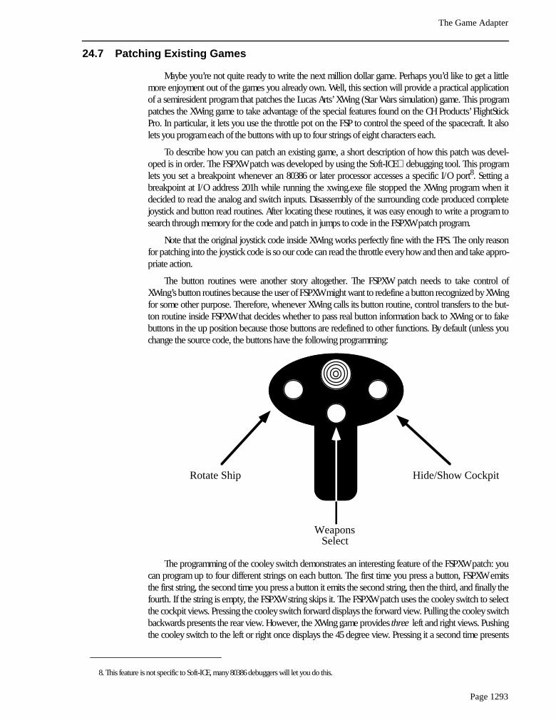
The button routines were another story altogether. The FSPXW patch needs to take control ofXWing’s button routines because the user of FSPXW might want to redefine a button recognized by XWingfor some other purpose. Therefore, whenever XWing calls its button routine, control transfers to the but-ton routine inside FSPXW that decides whether to pass real button information back to XWing or to fakebuttons in the up position because those buttons are redefined to other functions. By default (unless youchange the source code, the buttons have the following programming:
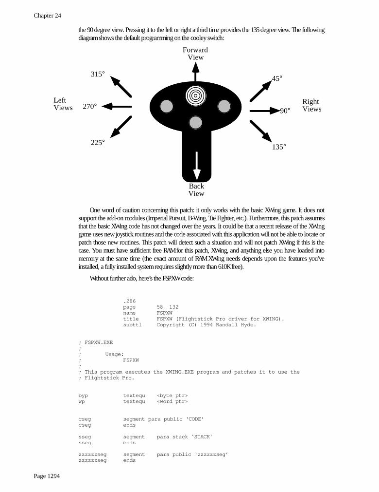
The programming of the cooley switch demonstrates an interesting feature of the FSPXW patch: youcan program up to four different strings on each button. The first time you press a button, FSPXW emitsthe first string, the second time you press a button it emits the second string, then the third, and finally thefourth. If the string is empty, the FSPXW string skips it. The FSPXW patch uses the cooley switch to selectthe cockpit views. Pressing the cooley switch forward displays the forward view. Pulling the cooley switchbackwards presents the rear view. However, the XWing game provides three left and right views. Pushingthe cooley switch to the left or right once displays the 45 degree view. Pressing it a second time presents
8. This feature is not specific to Soft-ICE, many 80386 debuggers will let you do this.
Rotate Ship
WeaponsSelect
Hide/Show Cockpit
Chapter 24
Page 1294
the 90 degree view. Pressing it to the left or right a third time provides the 135 degree view. The followingdiagram shows the default programming on the cooley switch:
One word of caution concerning this patch: it only works with the basic XWing game. It does notsupport the add-on modules (Imperial Pursuit, B-Wing, Tie Fighter, etc.). Furthermore, this patch assumesthat the basic XWing code has not changed over the years. It could be that a recent release of the XWinggame uses new joystick routines and the code associated with this application will not be able to locate orpatch those new routines. This patch will detect such a situation and will not patch XWing if this is thecase. You must have sufficient free RAM for this patch, XWing, and anything else you have loaded intomemory at the same time (the exact amount of RAM XWing needs depends upon the features you’veinstalled, a fully installed system requires slightly more than 610K free).
Without further ado, here’s the FSPXW code:
.286page 58, 132name FSPXWtitle FSPXW (Flightstick Pro driver for XWING).subttl Copyright (C) 1994 Randall Hyde.
; FSPXW.EXE;; Usage:; FSPXW;; This program executes the XWING.EXE program and patches it to use the; Flightstick Pro.
byp textequ <byte ptr>wp textequ <word ptr>
cseg segment para public ‘CODE’cseg ends
sseg segment para stack ‘STACK’sseg ends
zzzzzzseg segment para public ‘zzzzzzseg’zzzzzzseg ends
315°
270°
225°
45°
90°
135°
LeftViews
RightViews
ForwardView
BackView
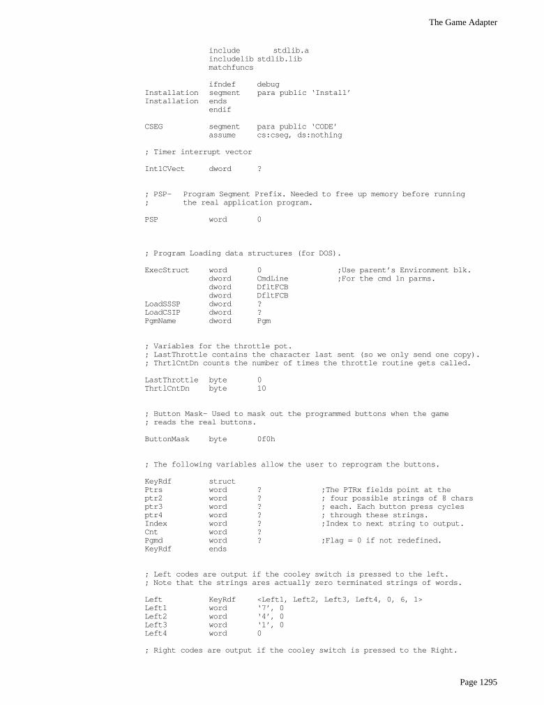
The Game Adapter
Page 1295
include stdlib.aincludelib stdlib.libmatchfuncs
ifndef debugInstallation segment para public ‘Install’Installation ends
endif
CSEG segment para public ‘CODE’assume cs:cseg, ds:nothing
; Timer interrupt vector
Int1CVect dword ?
; PSP- Program Segment Prefix. Needed to free up memory before running; the real application program.
PSP word 0
; Program Loading data structures (for DOS).
ExecStruct word 0 ;Use parent’s Environment blk.dword CmdLine ;For the cmd ln parms.dword DfltFCBdword DfltFCB
LoadSSSP dword ?LoadCSIP dword ?PgmName dword Pgm
; Variables for the throttle pot.; LastThrottle contains the character last sent (so we only send one copy).; ThrtlCntDn counts the number of times the throttle routine gets called.
LastThrottle byte 0ThrtlCntDn byte 10
; Button Mask- Used to mask out the programmed buttons when the game; reads the real buttons.
ButtonMask byte 0f0h
; The following variables allow the user to reprogram the buttons.
KeyRdf structPtrs word ? ;The PTRx fields point at theptr2 word ? ; four possible strings of 8 charsptr3 word ? ; each. Each button press cyclesptr4 word ? ; through these strings.Index word ? ;Index to next string to output.Cnt word ?Pgmd word ? ;Flag = 0 if not redefined.KeyRdf ends
; Left codes are output if the cooley switch is pressed to the left.; Note that the strings ares actually zero terminated strings of words.
Left KeyRdf <Left1, Left2, Left3, Left4, 0, 6, 1>Left1 word ‘7’, 0Left2 word ‘4’, 0Left3 word ‘1’, 0Left4 word 0
; Right codes are output if the cooley switch is pressed to the Right.
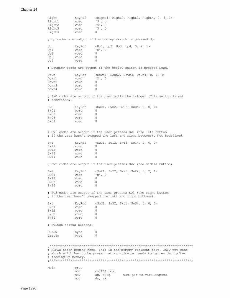
Chapter 24
Page 1296
Right KeyRdf <Right1, Right2, Right3, Right4, 0, 6, 1>Right1 word ‘9’, 0Right2 word ‘6’, 0Right3 word ‘3’, 0Right4 word 0
; Up codes are output if the cooley switch is pressed Up.
Up KeyRdf <Up1, Up2, Up3, Up4, 0, 2, 1>Up1 word ‘8’, 0Up2 word 0Up3 word 0Up4 word 0
; DownKey codes are output if the cooley switch is pressed Down.
Down KeyRdf <Down1, Down2, Down3, Down4, 0, 2, 1>Down1 word ‘2’, 0Down2 word 0Down3 word 0Down4 word 0
; Sw0 codes are output if the user pulls the trigger.(This switch is not; redefined.)
Sw0 KeyRdf <Sw01, Sw02, Sw03, Sw04, 0, 0, 0>Sw01 word 0Sw02 word 0Sw03 word 0Sw04 word 0
; Sw1 codes are output if the user presses Sw1 (the left button; if the user hasn’t swapped the left and right buttons). Not Redefined.
Sw1 KeyRdf <Sw11, Sw12, Sw13, Sw14, 0, 0, 0>Sw11 word 0Sw12 word 0Sw13 word 0Sw14 word 0
; Sw2 codes are output if the user presses Sw2 (the middle button).
Sw2 KeyRdf <Sw21, Sw22, Sw23, Sw24, 0, 2, 1>Sw21 word ‘w’, 0Sw22 word 0Sw23 word 0Sw24 word 0
; Sw3 codes are output if the user presses Sw3 (the right button; if the user hasn’t swapped the left and right buttons).
Sw3 KeyRdf <Sw31, Sw32, Sw33, Sw34, 0, 0, 0>Sw31 word 0Sw32 word 0Sw33 word 0Sw34 word 0
; Switch status buttons:
CurSw byte 0LastSw byte 0
;****************************************************************************; FSPXW patch begins here. This is the memory resident part. Only put code; which which has to be present at run-time or needs to be resident after; freeing up memory.;****************************************************************************
Main procmov cs:PSP, dsmov ax, cseg ;Get ptr to vars segmentmov ds, ax
The Game Adapter
Page 1297
; Get the current INT 1Ch interrupt vector:
mov ax, 351chint 21hmov wp Int1CVect, bxmov wp Int1CVect+2, es
; The following call to MEMINIT assumes no error occurs. If it does,; we’re hosed anyway.
mov ax, zzzzzzsegmov es, axmov cx, 1024/16meminit2
; Do some initialization before running the game. These are calls to the; initialization code which gets dumped before actually running XWING.
call far ptr ChkBIOS15call far ptr Identifycall far ptr Calibrate
; If any switches were programmed, remove those switches from the; ButtonMask:
mov al, 0f0h ;Assume all buttons are okay.cmp sw0.pgmd, 0je Sw0NotPgmdand al, 0e0h ;Remove sw0 from contention.
Sw0NotPgmd:
cmp sw1.pgmd, 0je Sw1NotPgmdand al, 0d0h ;Remove Sw1 from contention.
Sw1NotPgmd:
cmp sw2.pgmd, 0je Sw2NotPgmdand al, 0b0h ;Remove Sw2 from contention.
Sw2NotPgmd:
cmp sw3.pgmd, 0je Sw3NotPgmdand al, 070h ;Remove Sw3 from contention.
Sw3NotPgmd:mov ButtonMask, al ;Save result as button mask
; Now, free up memory from ZZZZZZSEG on to make room for XWING.; Note: Absolutely no calls to UCR Standard Library routines from; this point forward! (ExitPgm is okay, it’s just a macro which calls DOS.); Note that after the execution of this code, none of the code & data; from zzzzzzseg on is valid.
mov bx, zzzzzzsegsub bx, PSPinc bxmov es, PSPmov ah, 4ahint 21hjnc GoodReallocprintbyte “Memory allocation error.”byte cr,lf,0jmp Quit
GoodRealloc:
; Now load the XWING program into memory:
mov bx, seg ExecStructmov es, bx
Chapter 24
Page 1298
mov bx, offset ExecStruc ;Ptr to program record.lds dx, PgmNamemov ax, 4b01h ;Load, do not exec, pgmint 21hjc Quit ;If error loading file.
; Search for the joystick code in memory:
mov si, zzzzzzsegmov ds, sixor si, si
mov di, csmov es, dimov di, offset JoyStickCodemov cx, JoyLengthcall FindCodejc Quit ;If didn’t find joystick code.
; Patch the XWING joystick code here
mov byp ds:[si], 09ah ;Far callmov wp ds:[si+1], offset ReadGamemov wp ds:[si+3], cs
; Find the Button code here.
mov si, zzzzzzsegmov ds, sixor si, si
mov di, csmov es, dimov di, offset ReadSwCodemov cx, ButtonLengthcall FindCodejc Quit
; Patch the button code here.
mov byp ds:[si], 9ahmov wp ds:[si+1], offset ReadButtonsmov wp ds:[si+3], csmov byp ds:[si+5], 90h ;NOP.
; Patch in our timer interrupt handler:
mov ax, 251chmov dx, seg MyInt1Cmov ds, dxmov dx, offset MyInt1Cint 21h
; Okay, start the XWING.EXE program running
mov ah, 62h ;Get PSPint 21hmov ds, bxmov es, bxmov wp ds:[10], offset Quitmov wp ds:[12], csmov ss, wp cseg:LoadSSSP+2mov sp, wp cseg:LoadSSSPjmp dword ptr cseg:LoadCSIP
Quit: lds dx, cs:Int1CVect ;Restore timer vector.mov ax, 251chint 21hExitPgm
The Game Adapter
Page 1299
Main endp
;****************************************************************************;; ReadGame- This routine gets called whenever XWing reads the joystick.; On every 10th call it will read the throttle pot and send; appropriate characters to the type ahead buffer, if; necessary.
assume ds:nothingReadGame proc far
dec cs:ThrtlCntDn ;Only do this each 10th timejne SkipThrottle ; XWING calls the joystickmov cs:ThrtlCntDn, 10 ; routine.
push axpush bx ;No need to save bp, dx, or cx aspush di ; XWING preserves these.
mov ah, 84hmov dx, 103h ;Read the throttle potint 15h
; Convert the value returned by the pot routine into the four characters; 0..63:”\”, 64..127:”[“, 128..191:”]”, 192..255:<bs>, to denote zero, 1/3,; 2/3, and full power, respectively.
mov dl, almov ax, “\” ;Zero powercmp dl, 192jae SetPowermov ax, “[“ ;1/3 power.cmp dl, 128jae SetPowermov ax, “]” ;2/3 power.cmp dl, 64jae SetPowermov ax, 8 ;BS, full power.
SetPower: cmp al, cs:LastThrottleje SkipPIBmov cs:LastThrottle, alcall PutInBuffer
SkipPIB: pop dipop bxpop ax
SkipThrottle: neg bx ;XWING returns data in these registers.neg di ;We patched the NEG and STI instrssti ; so do that here.ret
ReadGame endp
assume ds:nothingReadButtons proc far
mov ah, 84hmov dx, 0int 15hnot aland al, ButtonMask ;Turn off pgmd buttons.ret
ReadButtons endp
; MyInt1C- Called every 1/18th second. Reads switches and decides if it; should shove some characters into the type ahead buffer.
assume ds:csegMyInt1c proc far
push dspush axpush bxpush dxmov ax, cseg
Chapter 24
Page 1300
mov ds, ax
mov al, CurSwmov LastSw, al
mov dx, 900h ;Read the 8 switches.mov ah, 84hint 15h
mov CurSw, alxor al, LastSw ;See if any changesjz NoChangesand al, CurSw ;See if sw just went down.jz NoChanges
; If a switch has just gone down, output an appropriate set of scan codes; for it, if that key is active. Note that pressing *any* key will reset; all the other key indexes.
test al, 1 ;See if Sw0 (trigger) was pulled.jz NoSw0cmp Sw0.Pgmd, 0je NoChangesmov ax, 0mov Left.Index, ax ;Reset the key indexes for all keysmov Right.Index, ax ; except SW0.mov Up.Index, axmov Down.Index, axmov Sw1.Index, axmov Sw2.Index, axmov Sw3.Index, axmov bx, Sw0.Indexmov ax, Sw0.Indexmov bx, Sw0.Ptrs[bx]add ax, 2cmp ax, Sw0.Cntjb SetSw0mov ax, 0
SetSw0: mov Sw0.Index, axcall PutStrInBufjmp NoChanges
NoSw0: test al, 2 ;See if Sw1 (left sw) was pressed.jz NoSw1cmp Sw1.Pgmd, 0je NoChangesmov ax, 0mov Left.Index, ax ;Reset the key indexes for all keysmov Right.Index, ax ; except Sw1.mov Up.Index, axmov Down.Index, axmov Sw0.Index, axmov Sw2.Index, axmov Sw3.Index, axmov bx, Sw1.Indexmov ax, Sw1.Indexmov bx, Sw1.Ptrs[bx]add ax, 2cmp ax, Sw1.Cntjb SetSw1mov ax, 0
SetSw1: mov Sw1.Index, axcall PutStrInBufjmp NoChanges
NoSw1: test al, 4 ;See if Sw2 (middle sw) was pressed.jz NoSw2cmp Sw2.Pgmd, 0je NoChangesmov ax, 0
The Game Adapter
Page 1301
mov Left.Index, ax ;Reset the key indexes for all keysmov Right.Index, ax ; except Sw2.mov Up.Index, axmov Down.Index, axmov Sw0.Index, axmov Sw1.Index, axmov Sw3.Index, axmov bx, Sw2.Indexmov ax, Sw2.Indexmov bx, Sw2.Ptrs[bx]add ax, 2cmp ax, Sw2.Cntjb SetSw2mov ax, 0
SetSw2: mov Sw2.Index, axcall PutStrInBufjmp NoChanges
NoSw2: test al, 8 ;See if Sw3 (right sw) was pressed.jz NoSw3cmp Sw3.Pgmd, 0je NoChangesmov ax, 0mov Left.Index, ax ;Reset the key indexes for all keysmov Right.Index, ax ; except Sw3.mov Up.Index, axmov Down.Index, axmov Sw0.Index, axmov Sw1.Index, axmov Sw2.Index, axmov bx, Sw3.Indexmov ax, Sw3.Indexmov bx, Sw3.Ptrs[bx]add ax, 2cmp ax, Sw3.Cntjb SetSw3mov ax, 0
SetSw3: mov Sw3.Index, axcall PutStrInBufjmp NoChanges
NoSw3: test al, 10h ;See if Cooly was pressed upwards.jz NoUpcmp Up.Pgmd, 0je NoChangesmov ax, 0mov Right.Index, ax ;Reset all but Up.mov Left.Index, axmov Down.Index, axmov Sw0.Index, axmov Sw1.Index, axmov Sw2.Index, axmov Sw3.Index, axmov bx, Up.Indexmov ax, Up.Indexmov bx, Up.Ptrs[bx]add ax, 2cmp ax, Up.Cntjb SetUpmov ax, 0
SetUp: mov Up.Index, axcall PutStrInBufjmp NoChanges
NoUp: test al, 20h ;See if Cooley was pressed left.jz NoLeftcmp Left.Pgmd, 0je NoChangesmov ax, 0mov Right.Index, ax ;Reset all but Left.mov Up.Index, ax

Chapter 24
Page 1302
mov Down.Index, axmov Sw0.Index, axmov Sw1.Index, axmov Sw2.Index, axmov Sw3.Index, axmov bx, Left.Indexmov ax, Left.Indexmov bx, Left.Ptrs[bx]add ax, 2cmp ax, Left.Cntjb SetLeftmov ax, 0
SetLeft: mov Left.Index, axcall PutStrInBufjmp NoChanges
NoLeft: test al, 40h ;See if Cooley was pressed Rightjz NoRightcmp Right.Pgmd, 0je NoChangesmov ax, 0mov Left.Index, ax ;Reset all but Right.mov Up.Index, axmov Down.Index, axmov Sw0.Index, axmov Sw1.Index, axmov Sw2.Index, axmov Sw3.Index, axmov bx, Right.Indexmov ax, Right.Indexmov bx, Right.Ptrs[bx]add ax, 2cmp ax, Right.Cntjb SetRightmov ax, 0
SetRight: mov Right.Index, axcall PutStrInBufjmp NoChanges
NoRight: test al, 80h ;See if Cooly was pressed Downward.jz NoChangescmp Down.Pgmd, 0je NoChangesmov ax, 0mov Left.Index, ax ;Reset all but Down.mov Up.Index, axmov Right.Index, axmov Sw0.Index, axmov Sw1.Index, axmov Sw2.Index, axmov Sw3.Index, axmov bx, Down.Indexmov ax, Down.Indexmov bx, Down.Ptrs[bx]add ax, 2cmp ax, Down.Cntjb SetDownmov ax, 0
SetDown: mov Down.Index, axcall PutStrInBuf
NoChanges: pop dxpop bxpop axpop dsjmp cs:Int1CVect
MyInt1c endpassume ds:nothing
; PutStrInBuf- BX points at a zero terminated string of words.; Output each word by calling PutInBuffer.
The Game Adapter
Page 1303
PutStrInBuf proc nearpush axpush bx
PutLoop: mov ax, [bx]test ax, axjz PutDonecall PutInBufferadd bx, 2jmp PutLoop
PutDone: pop bxpop axret
PutStrInBuf endp
; PutInBuffer- Outputs character and scan code in AX to the type ahead; buffer.
assume ds:nothingKbdHead equ word ptr ds:[1ah]KbdTail equ word ptr ds:[1ch]KbdBuffer equ word ptr ds:[1eh]EndKbd equ 3ehBuffer equ 1eh
PutInBuffer proc nearpush dspush bxmov bx, 40hmov ds, bxpushfcli ;This is a critical region!mov bx, KbdTail ;Get ptr to end of typeinc bx ; ahead buffer and make roominc bx ; for this character.cmp bx, buffer+32 ;At physical end of buffer?jb NoWrapmov bx, buffer ;Wrap back to 1eH if at end.
;NoWrap: cmp bx, KbdHead ;Buffer overrun?
je PIBDonexchg KbdTail, bx ;Set new, get old, ptrs.mov ds:[bx], ax ;Output AX to old location.
PIBDone: popf ;Restore interruptspop bxpop dsret
PutInBuffer endp
;****************************************************************************;; FindCode: On entry, ES:DI points at some code in *this* program which; appears in the ATP game. DS:SI points at a block of memory; in the XWing game. FindCode searches through memory to find the; suspect piece of code and returns DS:SI pointing at the start of; that code. This code assumes that it *will* find the code!; It returns the carry clear if it finds it, set if it doesn’t.
FindCode proc nearpush axpush bxpush dx
DoCmp: mov dx, 1000hCmpLoop: push di ;Save ptr to compare code.
push si ;Save ptr to start of string.push cx ;Save count.
repe cmpsbpop cxpop sipop dije FoundCode
Chapter 24
Page 1304
inc sidec dxjne CmpLoopsub si, 1000hmov ax, dsinc ahmov ds, axcmp ax, 9000hjb DoCmp
pop dxpop bxpop axstcret
FoundCode: pop dxpop bxpop axclcret
FindCode endp
;****************************************************************************;; Joystick and button routines which appear in XWing game. This code is; really data as the INT 21h patch code searches through memory for this code; after loading a file from disk.
JoyStickCode proc nearstineg bxneg dipop bppop dxpop cxretmov bp, bxin al, dxmov bl, alnot aland al, ahjnz $+11hin al, dx
JoyStickCode endpEndJSC:
JoyLength = EndJSC-JoyStickCode
ReadSwCode procmov dx, 201hin al, dxxor al, 0ffhand ax, 0f0h
ReadSwCode endpEndRSC:
ButtonLength = EndRSC-ReadSwCode
cseg ends
Installation segment
; Move these things here so they do not consume too much space in the; resident part of the patch.
DfltFCB byte 3,” “,0,0,0,0,0CmdLine byte 2, “ “, 0dh, 126 dup (“ “) ;Cmd line for programPgm byte “XWING.EXE”,0
byte 128 dup (?) ;For user’s name
The Game Adapter
Page 1305
; ChkBIOS15- Checks to see if the INT 15 driver for FSPro is present in memory.
ChkBIOS15 proc farmov ah, 84hmov dx, 8100hint 15hmov di, bxstrcmplbyte “CH Products:Flightstick Pro”,0jne NoDriverLoadedret
NoDriverLoaded: printbyte “CH Products SGDI driver for Flightstick Pro is not “byte “loaded into memory.”,cr,lfbyte “Please run FSPSGDI before running this program.”byte cr,lf,0exitpgm
ChkBIOS15 endp
;****************************************************************************;; Identify- Prints a sign-on message.
assume ds:nothingIdentify proc far
; Print a welcome string. Note that the string “VersionStr” will be; modified by the “version.exe” program each time you assemble this code.
printbyte cr,lf,lfbyte “X W I N G P A T C H”,cr,lfbyte “CH Products Flightstick Pro”,cr,lfbyte “Copyright 1994, Randall Hyde”,cr,lfbyte lfbyte 0
retIdentify endp
;****************************************************************************;; Calibrate the throttle down here:
assume ds:nothingCalibrate proc far
printbyte cr,lf,lfbyte “Calibration:”,cr,lf,lfbyte “Move the throttle to one extreme and press any “byte “button:”,0
call Wait4Buttonmov ah, 84hmov dx, 1hint 15hpush dx ;Save pot 3 reading.
printbyte cr,lfbyte “Move the throttle to the other extreme and press “byte “any button:”,0
call Wait4Buttonmov ah, 84hmov dx, 1int 15hpop bx
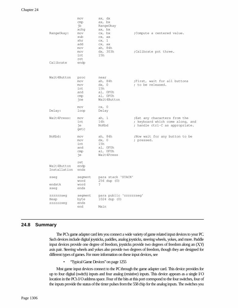
Chapter 24
Page 1306
mov ax, dxcmp ax, bxjb RangeOkayxchg ax, bx
RangeOkay: mov cx, bx ;Compute a centered value.sub cx, axshr cx, 1add cx, axmov ah, 84hmov dx, 303h ;Calibrate pot three.int 15hret
Calibrate endp
Wait4Button proc nearmov ah, 84h ;First, wait for all buttonsmov dx, 0 ; to be released.int 15hand al, 0F0hcmp al, 0F0hjne Wait4Button
mov cx, 0Delay: loop Delay
Wait4Press: mov ah, 1 ;Eat any characters from theint 16h ; keyboard which come along, andje NoKbd ; handle ctrl-C as appropriate.getc
NoKbd: mov ah, 84h ;Now wait for any button to bemov dx, 0 ; pressed.int 15hand al, 0F0hcmp al, 0F0hje Wait4Press
retWait4Button endpInstallation ends
sseg segment para stack ‘STACK’word 256 dup (0)
endstk word ?sseg ends
zzzzzzseg segment para public ‘zzzzzzseg’Heap byte 1024 dup (0)zzzzzzseg ends
end Main
24.8 Summary
The PC’s game adapter card lets you connect a wide variety of game related input devices to your PC.Such devices include digital joysticks, paddles, analog joysticks, steering wheels, yokes, and more. Paddleinput devices provide one degree of freedom, joysticks provide two degrees of freedom along an (X,Y)axis pair. Steering wheels and yokes also provide two degrees of freedom, though they are designed fordifferent types of games. For more information on these input devices, see
• “Typical Game Devices” on page 1255
Most game input devices connect to the PC through the game adapter card. This device provides forup to four digital (switch) inputs and four analog (resistive) inputs. This device appears as a single I/Olocation in the PC’s I/O address space. Four of the bits at this port correspond to the four switches, four ofthe inputs provide the status of the timer pulses from the 558 chip for the analog inputs. The switches you
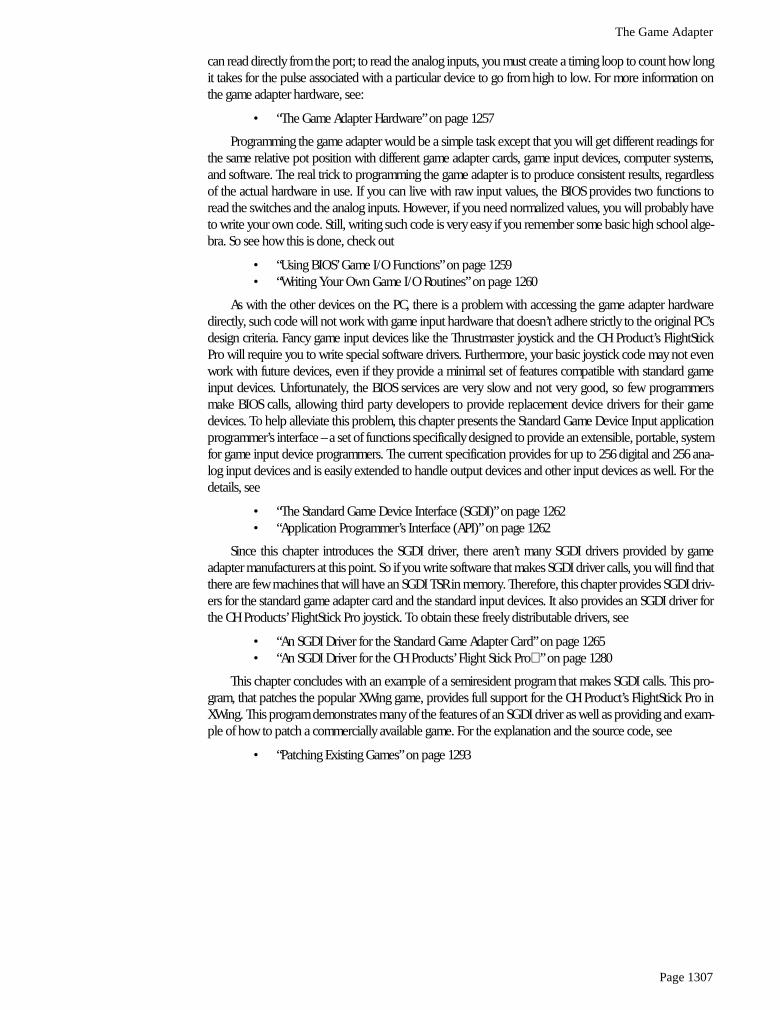
The Game Adapter
Page 1307
can read directly from the port; to read the analog inputs, you must create a timing loop to count how longit takes for the pulse associated with a particular device to go from high to low. For more information onthe game adapter hardware, see:
• “The Game Adapter Hardware” on page 1257
Programming the game adapter would be a simple task except that you will get different readings forthe same relative pot position with different game adapter cards, game input devices, computer systems,and software. The real trick to programming the game adapter is to produce consistent results, regardlessof the actual hardware in use. If you can live with raw input values, the BIOS provides two functions toread the switches and the analog inputs. However, if you need normalized values, you will probably haveto write your own code. Still, writing such code is very easy if you remember some basic high school alge-bra. So see how this is done, check out
• “Using BIOS’ Game I/O Functions” on page 1259• “Writing Your Own Game I/O Routines” on page 1260
As with the other devices on the PC, there is a problem with accessing the game adapter hardwaredirectly, such code will not work with game input hardware that doesn’t adhere strictly to the original PC’sdesign criteria. Fancy game input devices like the Thrustmaster joystick and the CH Product’s FlightStickPro will require you to write special software drivers. Furthermore, your basic joystick code may not evenwork with future devices, even if they provide a minimal set of features compatible with standard gameinput devices. Unfortunately, the BIOS services are very slow and not very good, so few programmersmake BIOS calls, allowing third party developers to provide replacement device drivers for their gamedevices. To help alleviate this problem, this chapter presents the Standard Game Device Input applicationprogrammer’s interface – a set of functions specifically designed to provide an extensible, portable, systemfor game input device programmers. The current specification provides for up to 256 digital and 256 ana-log input devices and is easily extended to handle output devices and other input devices as well. For thedetails, see
• “The Standard Game Device Interface (SGDI)” on page 1262• “Application Programmer’s Interface (API)” on page 1262
Since this chapter introduces the SGDI driver, there aren’t many SGDI drivers provided by gameadapter manufacturers at this point. So if you write software that makes SGDI driver calls, you will find thatthere are few machines that will have an SGDI TSR in memory. Therefore, this chapter provides SGDI driv-ers for the standard game adapter card and the standard input devices. It also provides an SGDI driver forthe CH Products’ FlightStick Pro joystick. To obtain these freely distributable drivers, see
• “An SGDI Driver for the Standard Game Adapter Card” on page 1265• “An SGDI Driver for the CH Products’ Flight Stick Pro” on page 1280
This chapter concludes with an example of a semiresident program that makes SGDI calls. This pro-gram, that patches the popular XWing game, provides full support for the CH Product’s FlightStick Pro inXWing. This program demonstrates many of the features of an SGDI driver as well as providing and exam-ple of how to patch a commercially available game. For the explanation and the source code, see
• “Patching Existing Games” on page 1293

Chapter 24
Page 1308