Embed Size (px)
Citation preview

THE PAST, PRESENT AND FUTURE OF SATELLITE
COMMUNICATIONS
John V. Evans
1. Introduction
The world's first commercial communications satellite "Early Bird," (later renamed INTELSAT
I) was placed by NASA into a geosynchronous orbit above the Atlantic in 1965. Providing 240
voice circuits between the United States and Europe, this single satellite had a capacity almost
equal to that of all of the RF/coaxial cables laid under the Atlantic up to that time. It could,
moreover, be used for relaying television, which the undersea cables of that era could not. Since
1965, several hundred commercial communications satellites have been launched to provide both
domestic and international communications. Used initially for completing long-distance (e.g.,
overseas) telephone circuits, satellites provided a means of establishing a truly global telecommu-
nications system in which small countries for the first time had direct access to the major cities of
the world. With the advent of fiber optic cables, the fraction of overseas telephone traffic carried
on satellites has declined, although it still amounts to about 30 percent. Satellites today are the
prime means of distributing television pictures around the globe, either to cable head ends or di-
rectly to subscribers. Satellites are also increasingly being used to provide private data networks
for companies (such as banks) that have widely distributed offices. This service usually involves
a central large (hub) station linked to many very small aperture terminals (VSATs).
Early development of satellite communications is traced in Section 2, and Section 3 de-
scribes current efforts to create global satellite systems providing personal communications
(voice, fax, and paging) services to users equipped with cellphone-like terminal. Section 4 pre-
sents a discussion of plans announced by large (mostly U.S.) corporations to establish satellite
1

J. V. Evans
systems to deliver multimedia services (such as Internet access, video streaming, telemedicine,
and teleeducation) at high data rates to offices and homes equipped with small fixed terminals.
2. The Past
2.1 INTELSAT
Bell Telephone Laboratories built the first active repeater satellite (Telstar I) that received and re-
transmitted simultaneously. This satellite, operating at 4 and 6 GHz, was placed into a 1,000 by
6,000-km elliptical orbit in 1962. Later the same year, the RCA-built Relay satellite operating at
4.2 and 1.7 GHz was placed into a similar orbit. As a result of these successful demonstrations,
the U.S. Congress passed the Satellite Communications Act in 1962. This created a new private
company (COMSAT) charged with exploiting satellite communications technology with the goal of
improving the world's communications. In 1964, with the assistance of the U.S. State Depart-
ment, an international organization called INTELSAT was created to operate such a global satellite
telecommunications system. COMSAT was named U.S. Signatory to INTELSAT, as well as
technical manager. This latter role ended in 1978.
Fig. 1 Distribution of the INTELSAT satellites (circa 1998).
Modern Radio Science 1999
2
1S-704@66°E1S-804@640E]S-602@63°EIS-604@60°EIS-703@57°EIS-510@33°E
IS-805(»304.5°E
1S-7O6@3O7°EIS-709@310°E
[email protected]°EIS-601(g325.5°[email protected]@330.5°[email protected]°[email protected]
[email protected]°[email protected]°E.
IS-705@3420ErIS-707@359°E'
IS-5i3@183°E1S-7O1@18O»ElSiT02@177°EIS-802@174°E
DE-ORBITED
IS-505®72«E

J. V. Evans
Figure 1 depicts the arrangement of satellites in the INTELSAT system. Satellites are
placed in geostationary orbits over the major oceans. Any pair of earth stations in view of the
same satellite can, in principle, establish a link, and there are now several thousand such links in
the INTELSAT system. Initially, service was provided at C-band (roughly 6 GHz for the uplink
frequency and 4 GHz for the downlink); to achieve added capacity, repeaters were later incorpo-
rated in the Ku-band (roughly 14-GHz uplink and 12-GHz downlink). Table 1 lists the wave-
lengths for bands that are available internationally (i.e., as agreed upon at the ITU) for commercial
satellite communications, and which are referred to herein.
Band
Wavelength (cm)
Table 1
UHF
-75.0
Wavelengths for commercial communications satellites,
L-band
-18.6
S-band(up/down)
-15.1M3.7
C-band(up/down)
-4.0/-7.5
Ku-band(up/down)
-2.5/-2.1
Ka-band(up/down)
-1.6/-1.0
Q/V-band(up/down)
~0.8/~0.6
An indication of the growth of the INTELSAT system can be seen by inspecting the capa-
bilities of the individual satellites employed (Table 2). From INTELSAT I, which could handle
240 circuits, to the INTELSAT IX satellites now being built capable of handling approximately
40,000 circuits, we see a large increase in design life, mass, primary power, number of transpond-
ers, etc. The technical developments necessary to achieve the added capacity indicated by Table
2 are summarized below. Since INTELSAT was the driver for satellites of ever-greater capacity,
the capabilities indicated in Table 2 were essentially "state of the art," and similar satellites were
ordered from the principal manufacturers (initially Hughes, Ford Aerospace, and RCA Astro) by
other systems that were inaugurated later. These included regional systems (Eutelsat and Arab-
sat) and domestic systems for countries such as Indonesia (Palapa), Mexico (Morelos), and Aus-
tralia (Aussat).
Modem Radio Science 1999
3

J. V. Evans
2.2 Satellite Technology
2.2.1 System Concept
A communications satellite consists of a number of active repeaters which receive signals broad-
cast from one or more earth stations on the ground, amplify them and retransmit them at a new
(usually lower) frequency to one or more receiving earth stations. The change in signal frequency
is necessary because the amplification that must be employed to overcome path loss far exceeds
the amount of isolation that could be achieved between separate transmit and receive antennas on
board the satellite if these were at the same frequency.
Links can be established by any pair of earth stations that agree to receive the signals
transmitted by each other (after appropriate frequency translation in the satellite). Since a geosta-
tionary satellite is visible from a large portion of the earth's surface, a large number of links can
be established. The stations may in fact transmit on more than a single frequency and/or polariza-
tion, depending on the amount of traffic they carry. The most efficient use of the satellite trans-
ponder capacity is achieved by combining as many voice circuits as possible onto a single RF car-
rier. This is accomplished at the earth station either by assigning the voice circuits to adjacent 4 -
kHz frequency channels at baseband before modulating the RF carrier, or, in the case of digital
voice channels, by time-division multiplexing the bit streams into a single high-rate stream. While
analog circuit combining was initially employed, the most telephone circuits have since been con-
verted to digital operation. Initially it was the practice to keep the satellites as simple as possible
and place the burden of completing the radio link on the earth station. This lead to a requirement
for large earth station antennas (up to 100 feet in diameter), as shown in Figure 2. As satellite
technology improved, the need for such antennas receded and today few, if any, larger than 10
meters in diameter are required.
Modern Radio Science 1999
4

Z I I I I |H \l [771 I I I \lz § I " • £ - 1 i ~ ^ 8 8 I— •*? h I o 2 £ .§ "a r- g g o
U ^ (s O £ CN vA <J § .2 oo" * - £
2 < £ oo „ ~ ^ S | ffl a I'Z > ~ I i I'll 8. ^ 1 1 I + J
r___Z il hi n IHS i i i !
CJ J^ ( N N < C J C Q W W W Ul M 4 U N O W-T •*" i - <
G g « | 8 2 | 1 •-- 5 o | M. § 8 g * 8 "g = Z
i r s -• is in Hi inn § i o i i
^ IS - i » - 11 i ! 5< 11 s o o . s igz I i = i s S. I i S. «? s a i ^ § Ig •
I 2 > .0 § s . 5 1 .g-1 < 1 1 | ^ & :^ z •? => a § ° I "S S. < 2 ^ ^ S S + - S 5 c4 2 - U i i < N N O J Sm 4 3 o r „• ?: < u <'3'Si F-Q < o 1
3 r a £ of N ' * S «- N
^ H - J -g ^ g g o s o « c |•§ « U Ow Z CN ^ ^ t - < U <
|^ - I = j ij § j j |
i 3 " * ^ 1 1 I I SK 11" u O Z Z ^ _ U - 1 H <
3 - i " % | u 1S 3 J z J l I 10 g M I
^ •? s
2 - 8 - 3 I 2| I 1 z 1 § § o o o - l
g |llljj|l|g^illl|3l 111 [l l l l l l lMl j i l

J. V. Evans
Fig. 2 Earth station antennas employed by COMSAT to communicate with the Atlantic satellites.These antennas are located at Etam, West Virginia, and are 105, 45, and 90 feet in diameter (as oneapproaches the camera). The smaller antenna operates at Ku-band, while the two larger antennasare C-band.
1.7..1 Communications payload design.
The satellite's communications payload receives the signals transmitted from the ground, ampli-
fies them, and retransmits them (usually at a new, lower frequency). Figure 3 sketches the main
elements of a payload for a Ku-band domestic satellite.
For a geostationary satellite overhead, the distance from the earth station is 35,860 km and
for a satellite on the horizon the distance is 41,750 km. Signals received at a satellite from earth
station antennas for these two cases experience attenuation of 162 dB and 163 dB, respectively.
To overcome this, high-power transmitters (up to 12-kW) coupled to high-gain (50 to 60 dB) an-
tennas are employed at the earth stations (Figure 2). This permits the satellite transponder to re-
ceive signals that are considerably stronger than the unwanted Johnson noise in the receiver. Typi-
cal early satellite transponders operated with an output power capability in the range 5 to 20 W.
Thus, the satellite- to-earth link usually operated within lower margins than the earth-to-satellite
link. More recently, however, transponder powers have been raised to as high as 120 W to per-
mit reception for direct-to-the home TV with very small antennas (e.g., 66 cm in diameter).
Modern Radio Science 1999
6

J. V. Evans
Fig. 3 Typical arrangement of pay load components in a satellite. Horizontal and vertical polarizedsignals (H and V) are selected via an ortho mode transducer (OMT) and amplified by receivers (eachof which has a spare). Signals are separated into channels via input multiplexers (MUX) and recom-bined by output mulitiplexers. Each channel has its own channel amplifier and travelling wave tube(TWT). The hybrids (H) and switches allow for routing around failed TWTs.
2.2.3 Channelization
The first attempt to increase communications capacity was made by increasing the bandwidth of
the onboard transponders to occupy an increasing fraction of the assigned frequency band. The
available satellite transmitter power then had to be shared among a larger number of RF carriers.
Careful control of power levels that radiated from each earth station was also required to prevent
any one carrier from capturing an undue share of the power. The increased interference between
the carriers resulting from the mixing that occurs in the final amplifier, however, rendered this ap-
proach unsatisfactory; it was then necessary to employ several transponders, each designed to
operate over only a portion of the assigned band. This change created a need for microwave filters
with little attenuation in their passbands and steep skirts at the edges of their bands. This re-
sponse was achieved by using elliptic function filters in which a series of microwave cavities are
cascaded together. To achieve the proper response, it is necessary to couple energy from the first
to the last cavity independently of any intervening cavities. COMSAT Laboratories developed a
means for accomplishing this by exciting each cavity with two orthogonal modes and coupling
these independently from cavity to cavity. This technology was critical to minimizing the guard
bands needed between transponders. Figure 4 shows the response achieved using this in a mod-
Modern Radio Science 1999
Ku-BsndUplink: 14-5 GHzDownlink: 11.7-12.2 GHz
RECEIVER
RECEIVER
RECEIVER
RECEIVER
JPF
OM
TC i ^
111EH15
N-1 ™ &-B -©wm
SHAMPI
PPT^
TVVTJ
E££MCHAM3
EJHMJ5
BCHAMPI-
N - 9
vmrn
"TWf
Q£
a-rcR
Ii
EHAMPI
CHAMPf-
TwT
H
H

J. V. Evans
ern microwave multiplexer unit. Most current satellite systems employ transponder bandwidths
in the range of 36 to 54 MHz, although INTELSAT employs transponders with 72 MHz band-
width.
FREQUENCY (MMz;
Fig. 4 The response of a set of microwave cavity filters coupled to a waveguide run to provide ameans of connecting the outputs (i.e., multiplexing) a set of transponders in a way that minimizestheir mutual interference and/or interaction. (Courtesy of Ford Aerospace Corporation.).
2.2.4 Antenna Technology
A second technological advance has been to use the assigned band (say 500 MHz) available at C-
band several times on the same satellite. This can be accomplished by using antenna beams that
illuminate separate service areas and achieve excellent isolation (i.e., low sidelobe levels) from one
another. INTELSAT pioneered the application frequency reuse and extended the concept by us-
ing overlapping beams in which isolation is accomplished through orthogonal circular polarization
for the two beams.
Beams are "shaped" to cover an irregular service area or footprint. To create the shape,
long-focal-length reflectors (which can be illuminated by horns offset from the axis without intro-
ducing large coma lobes) are used. Each of the horns in the array must be fed by an appropriate
fraction of transmitted power at the proper phase to achieve the desired flat-topped, sharp-sided
response. This is accomplished using a distribution network consisting of an arrangement of co-
axial power splitters and transmission lines. For domestic or regional satellites, it is simpler to
achieve beam shaping with a single feed horn and distorting the reflector to achieve the desired
contour.
Modern Radio Science 1999
r 73c
0
10
20
30
40
50
IO
0
5
10
1
IS
20
i-12 220
I
I
8

J. V. Evans
2.2.5 Compression and Circuit Multiplication
In the terrestrial telephone network, digital transmission of voice signals was introduced to im-
prove quality and reliability, and to reduce the need for maintenance. Typically, the analog voice
signal arriving at the first switch is sampled 8,000 times per second and assigned an 8 (or 7) bit
digital word that defines its amplitude and polarity. The resulting 64 (or 56) kb/s digital bit
stream is then sent over the long-distance portion of the circuit. In the INTELSAT system, cod-
ers were introduced, employing adaptive pulse-code modulation which reduced this rate to 32
kb/s. Speech interpolation equipment was also introduced which could seize inactive circuits for
active speakers (in a typical voice conversation, only 40 percent of circuit capacity is in use at a
given time). These two developments allowed four voice channels to be created from a single 64
kb/s circuit. Standards have since been developed that achieve toll-quality voice using digital en-
coders operating at low as 16 and 8 kb/s. These coders capture the setting of the vocal tract and
the manner in which it is being excited, and transmit this information rather than the original ana-
log signal.
Television signals are now also transmitted digitally, following compression to remove re-
dundancy. Standards (such as MPEG2) define how this is carried out and permit the delivery of
NTSC television with good (studio) quality at rates as low as 6 to 8 Mb/s.
2.3 Mobile Communications
2.3.1 Inmarsat
Commercial use of satellites for mobile communications began with the 1976 COMSAT/ Marisat
system. Ultrahigh frequency (UHF) and L-band (Table 1) satellites were positioned over the At-
lantic and Pacific oceans. The U.S. Navy used the UHF capacity, while the L-band capacity was
intended for a commercial service for mariners. Shipboard terminals consisted of an above-deck,
1-m-diameter antenna gimballed to remain locked on the satellite and protected from the elements
by a radome, while below deck would be a telephone handset, fax, and/or teleprinter terminal
(Fig. 5). Feeder links were provided at C-band via "coast" earth stations at Southbury, Connecti-
cut, and Santa Paula, California, which were connected to the public switched network.
Modern Radio Science 1999
9

10 J. V. Evans
Fig. 5 Shipboard Inmarsat terminal radome-enclosed antenna.
The system became global with the addition of a third satellite over the Indian Ocean and,
in 1979, was turned over to the newly formed Inmarsat international organization to manage.
Inmarsat, which is headquartered in London, is a treaty organization with 81 members.
In 1991, Inmarsat deployed four Inmarsat-2 satellites constructed to its own specifications.
Two, known as Atlantic East and Atlantic West (see Fig. 6), were placed over the Atlantic to
handle the large amount of traffic in that region. These satellites, like their predecessors, em-
ployed a single L-band global beam for servicing mobile users. This, combined with the limited
band of frequencies (28 MHz) available for this service at L-band, restricted the number of simul-
taneous users. In response to traffic growth, two approaches have been taken to increase the
availability of a circuit. One involves terminal design and the other entails frequency reuse.
Fig. 6 Coverage patterns of the Inmarsat-2 satellites and locationsof the coast earth stations operated by COMSAT.
The original (Inmarsat-A) terminal employed analog (FM) modulation of the L-band signals
and 50-kHz channel spacing. About 20,000 such terminals are installed on vessels around the
Modern Radio Science 1999

J. V. Evans 11
globe. To satisfy the demand for smaller terminals and to create more channels, Inmarsat intro-
duced two new services known as Inmarsat-B, and Inmarsat-M (described in Table 3) that oper-
ate in narrower channels than Inmarsat-A. In 1996, the first two of five Inmarsat-3 satellites were
launched. These satellites reuse the authorized frequencies in up to five "spot" beams, which can
be selected for their coverage of land. These beams provide higher EIRP, making it possible for
still-smaller terminals to operate within the system, and a "mini-M" terminal (Table 3) the size
of a laptop computer was made available in January 1977. It sells for about $3,000, with a usage
charge (fully terminated) of $3.00 per minute.
2.3.2 Other Land-Mobile Systems
Additional land-mobile satellite systems have been established by some countries. These all op-
erate either at L- or S-band (Table 1), since longer wavelengths provide a larger collecting area for
an omnidirectional antenna.
Table 3 Standard services of the Inmarsat system.
Features
Mobile to/from Satellite,L-Band (GHz)Fixed to/from Satellite,C-Band (GHz)Minimum Channel Spacing (kHz)
Users per Carrier
Access Method Modulation
FEC Coding Rate
Speech Coding Algorithm
Voice Coding Rate (kb/s)
Inmarsat-A
1.6/1.5
6/4
50
1
FDMACompanded FMN/A
N/A
N/A
Inmarsat-B
1.6/1.5
6/4
20
1
FDMAO-QPSK3/4
Adaptivepredictivecoding(APC)16
Inmarsat-M
1.6/1.5
6/4
10
1
FDMAO-QPSK3/4 (forsubband bits)Improvedmulti-bandexcitation(IMBE)6.4 (incl. er-ror correctionbits)
Mini-M
1.6/1.5
6/4
5
1
FDMAO-QPSK2/3 (forsuband bits)Advancedmultibandexcitation(AMBE)4.8 (incl.correctionbits)
In North America, the U.S. and Canada operate two satellites in what is called the MS AT
system. This system can provide service to vehicles (cars, trucks, etc.) and is similar in capability
Modern Radio Science 1999

12 J. V. Evans
to the Inmarsat-M system (Table 3) noted above. Australia has implemented an L-band system
known as OPTUS, and the Japanese have an S-band system called N-Star. None of these sys-
tems are powerful enough to permit operation with small handheld terminals, and new systems
proposed to provide this capability are described in Section 3.
3. The Present
Satellite technology is moving toward providing services to individual customers. The earliest ad-
vances in this direction have been satellite systems that deliver television direct to the home
(DTH). These systems have benefited from the increased prime power that can now be generated
on board satellites (currently 10 kW or more), allowing the operation of a sizable number (>16)
high-power (>100 W) Ku-band transponders. Another contributor to the success of these sys-
tems, at least in the U. S., has been the development of powerful digital compression schemes
that permit as many as 10 TV channels to be transmitted via a single transponder, and the picture
to be recovered in a set-top box containing special purpose, very-large-scale digital integrated
(VLSI) circuits manufactured at low cost.
Next to be conceived and developed were satellite systems that provide cellular-like voice
service to mobile users equipped with small handheld terminals. Three such systems with global
or nearly global coverage are under construction, and two more are seeking financing. Market
studies have identified four potential markets: international business travelers (primarily business
travelers from the developed world visiting less-developed countries), national roamers (primarily
business travelers needing mobile communications in their own countries, but who travel beyond
the reach of terrestrial cellular systems), national rural fixed service (an extension of the national
fixed services to regions where they are presently unobtainable), and government agencies (law
enforcement, fire, public safety, and other services). The designs of the global systems discussed
represent different assumptions concerning the business to be attracted from these four segments.
The subsections that follow discuss the five proposed systems that are proceeding. The Iridium,
Globalstar, and ICO systems appear to have the best chance of being fielded, while financing for
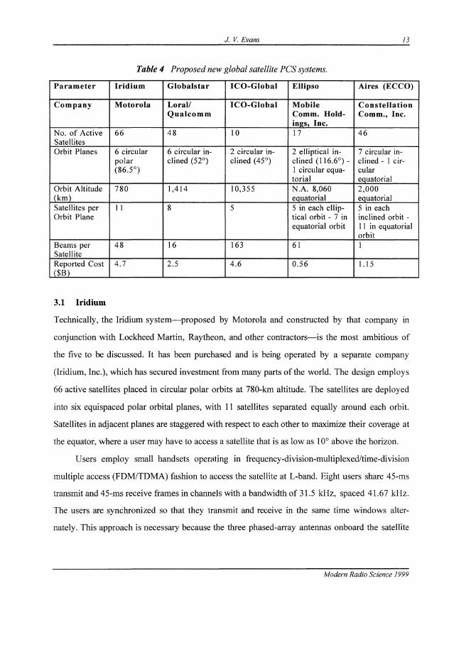
the others remains to be completed. Table 4 summarizes the parameters of these five systems.
Modern Radio Science 1999
Parameter
Company
No. of ActiveSatellitesOrbit Planes
Orbit Altitude(km)Satellites perOrbit Plane
Beams perSatelliteReported Cost($B)
Table 4
Iridium
Motorola
66
6 circularpolar(86.5°)
780
11
48
4.7
/ V. Evans
Proposed new global satellite PCS systems.
Globalstar
Loral/Qualcomm
48
6 circular in-clined (52°)
1,414
8
16
2.5
ICO-Global
ICO-Global
10
2 circular in-clined (45°)
10,355
5
163
4.6
Ellipso
MobileComm. Hold-ings, Inc.17
2 elliptical in-clined (116.6°) -1 circular equa-torialN.A. 8,060equatorial5 in each ellip-tical orbit - 7 inequatorial orbit
61
0.56
13
Aires (ECCO)
ConstellationComm., Inc.
46
7 circular in-clined - 1 cir-cularequatorial2,000equatorial5 in eachinclined orbit -11 in equatorialorbit1
1.15
3.1 Iridium
Technically, the Iridium system—proposed by Motorola and constructed by that company in
conjunction with Lockheed Martin, Raytheon, and other contractors—is the most ambitious of
the five to be discussed. It has been purchased and is being operated by a separate company
(Iridium, Inc.), which has secured investment from many parts of the world. The design employs
66 active satellites placed in circular polar orbits at 780-km altitude. The satellites are deployed
into six equispaced polar orbital planes, with 11 satellites separated equally around each orbit.
Satellites in adjacent planes are staggered with respect to each other to maximize their coverage at
the equator, where a user may have to access a satellite that is as low as 10° above the horizon.
Users employ small handsets operating in frequency-division-multiplexed/time-division
multiple access (FDM/TDMA) fashion to access the satellite at L-band. Eight users share 45-ms
transmit and 45-ms receive frames in channels with a bandwidth of 31.5 kHz, spaced 41.67 kHz.
The users are synchronized so that they transmit and receive in the same time windows alter-
nately. This approach is necessary because the three phased-array antennas onboard the satellite
Modern Radio Science 1999

14 J. V. Evans
(Figure 7a) are used for both transmitting and receiving. Figure 7b shows the 48 spot beam that
these phased arrays form, projected onto the earth at the equator.
The Iridium system is unique in that it is designed to achieve essentially global coverage
with only a small number of gateway earth stations that connect to the public switched network
(in all, 11 will be built). To this end, the satellites are designed to route traffic from satellite to
satellite. Each satellite employs onboard processing to demodulate each arriving TDMA burst,
determine how to route it, and then retransmit it to its next destination. This can be to the
ground if a gateway earth station is in view, or to one of the four nearest satellites: the one
ahead or behind in the same orbital plane, or the nearest in either orbital plane to the east or west.
These satellite cross-links operate at 23 GHz, while the links to the gateway earth stations are at
20 GHz. Each satellite is capable of handling as many as 1,100 simultaneous calls. The Iridium
satellites are station-kept using onboard propulsion in order to overcome atmospheric drag and to
have sufficient fuel for an 8-year life.
Fig. 7a. Sketch of the Iridium satellite showing Fig. 7b. The 48 spot beams produced by thethe three phased-array antennas that are canti- phased-array antennas shown in Figure 7alevered off the three sides of the spacecraft bus. projected onto the earth at the equator.
3.2 Globalstar
The Globalstar system is being purchased by a limited partnership in which Loral and Qualcomm
of the United States are principal partners. The satellites are currently being assembled in Italy
(by Alenia Spazio), while Qualcomm has developed much of the ground segment. Unlike the
Iridium system, which offers true global service, Globalstar's business plan calls for launching the
Modern Radio Science 1999
330 in.BUS SECTION
SOLARARRAY PANEL
BATTERY & "RADIATOR
MAIN MISSIONANTENNA
PANEL
GATEWAY'ANTENNA
•COMMUNICATIONSSECTION
180 in.
CROSS-LINKANTENNA
+30° +20° +10° 0° -10° -20°
+20°
+ 10°
0"
-10'
-20"
J. V. Evans 15
space segment and franchising its use to partners in different countries. More than 90 such rela-
tionships have already been established.
The Globalstar system will employ 48 satellites in eight planes of six satellites each. The
satellite orbits are circular, at 1,414 km and 52° inclination. The use of an inclined orbit concen-
trates the available satellite capacity at lower latitudes where the largest populations exist; little
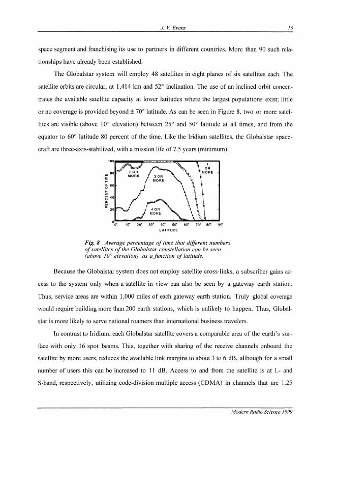
or no coverage is provided beyond ± 70° latitude. As can be seen in Figure 8, two or more satel-
lites are visible (above 10° elevation) between 25° and 50° latitude at all times, and from the
equator to 60° latitude 80 percent of the time. Like the Iridium satellites, the Globalstar space-
craft are three-axis-stabilized, with a mission life of 7.5 years (minimum).
Fig. 8 Average percentage of time that different numbersof satellites of the Globalstar constellation can be seen(above 10° elevation), as a function of latitude.
Because the Globalstar system does not employ satellite cross-links, a subscriber gains ac-
cess to the system only when a satellite in view can also be seen by a gateway earth station.
Thus, service areas are within 1,000 miles of each gateway earth station. Truly global coverage
would require building more than 200 earth stations, which is unlikely to happen. Thus, Global-
star is more likely to serve national roamers than international business travelers.
In contrast to Iridium, each Globalstar satellite covers a comparable area of the earth's sur-
face with only 16 spot beams. This, together with sharing of the receive channels onboard the
satellite by more users, reduces the available link margins to about 3 to 6 dB, although for a small
number of users this can be increased to 11 dB. Access to and from the satellite is at L- and
S-band, respectively, utilizing code-division multiple access (CDMA) in channels that are 1.25
Modern Radio Science 1999
80
60
40
20
0
lit
iVLo
UiotrHi
2 OHMORE 3 OR
MORE
tOR
MORE
4 ORMORE
0° 10° ?(f 30° 40° 50° fi0° 70° 80* 90"
LATITUDE

16 J.V. Evans
MHz in bandwidth. Voice is encoded at 1 to 9 kb/s, depending on speaker activity. The satellites
use simple "bent pipe" transponders, with the feeder links at C-band.
Since all 16 beams of all of the 48 satellites are always active, each satellite in view will
pick up a subscriber's signal and retransmit it in its feeder link. By tracking all the satellites in
view of a given gateway earth station, two channels can be open to the subscriber. The channel
with the stronger signal can connect to the public switched network. This should mitigate block-
ing by buildings and provide a "soft" handoff from satellite to satellite. Globalstar hopes to have
it system in operation by late 1999. Eight of the 48 satellites have been launched so far (Dec.
1998).
3.3 ICO
ICO-Global is a spin-off from Inmarsat, which owns 15 percent of the corporation. The remain-
der is presently owned by Inmarsat signatories, and by Hughes (the builder of the spacecraft) and
TRW. ICO-Global has chosen an intermediate circular orbit for its system (10,355-km altitude),
with 10 satellites arranged 5 in each of two inclined circular orbits. The inclination of the orbits is
45°—making it the lowest of the three systems. Because each satellite must serve a large portion
of the earth's surface, a total of 163 spot beams will be used. Routing signals to the correct spot
beam then becomes difficult with analog [e.g., surface acoustic wave (SAW)] filters, and will in-
stead be done with a digital filter bank [which performs a fast Fourier transform (FFT) on signals
arriving from the gateway earth station]. To access a given spot beam, gateway earth stations
must transmit at a particular frequency.
A true TDMA scheme has been adopted for the service links, with six subscribers multi-
plexed into channels 25.2 kHz in width at a bit rate of 36 kb/s. However, a soft handoff (e.g.,
beam to beam) is not automatic, and it is difficult to exploit dual-satellite visibility.
Hughes Space and Communications Division is building the ICO satellites, and a team con-
sisting of NEC, Ericsson, and Hughes Network Systems Division is building the ground segment.
ICO hopes to have its system in operation by year 2000.
Modern Radio Science 1999

J. V. Evans 17
3.4 EUipso and Aires
The Ellipse* and Aries systems are both currently believed to be attempting to secure investors.
Both aim to be low-cost entrants to the market. These systems would initially deploy satellites
into circular orbits above the equator, and later would add satellites in additional inclined (ellipti-
cal in the case of Ellipso) orbits to cover higher latitudes.
4. The Future
4.1 Introduction
Fixed-satellite services were first offered by INTELSAT at C-band frequencies (refer to Table 1).
The earth terminal antennas in the INTELSAT system were large, but have decreased in size with
the launch of more powerful satellites. As other satellites providing domestic or regional fixed-
satellite services were deployed, agreement had to be reached on their separation along the orbital
arc. To avoid mutual interference between systems caused by an earth station with a small an-
tenna illuminating satellites on either side of the wanted one, it was necessary to agree on the
spacing between satellites using the same frequency band; this is now set at 2°.
Absence of suitable C-band orbital slots drove the construction of satellites operating at
Ku-band, and most INTELSAT satellites are built with transponders operating in both bands.
DTH TV broadcasting satellites also operate at Ku-band. It is now nearly impossible to secure
an orbital location where satellite can be operated at C- or Ku-bands without interfering with its
neighbors. This has spurred interest in systems operating at Ka-band (Table 1).
Until recently, interest in this band has been confined to experimental satellites launched by
Japan, the United States, and Italy. This is because, unlike at C-band, rain greatly attenuates Ka-
band signals (and to some lesser extent, Ku-band signals), making this a difficult band in which to
provide satellite services. A group of private U.S. investors proposed a Ka-band satellite sys-
tem. It would provide a global wideband data distribution capability known as the Callingsm Net-
work, later renamed Teledesic. This system was to employ 840 low-altitude satellites, each of
which could relay to its eight nearest neighbors and provide users (who had sufficiently large
terminals) access to rates up to 1.2 Gb/s.
Modern Radio Science 1999

18 J. V. Evans
Despite the ambitious nature of this proposal, Teledesic organization was successful in
lobbying at the World Administration Radio Conference for Ka-band frequency assignments.
This caused the FCC to proceed with a Notice of Inquiry offering other applicants the opportu-
nity to seek Ka-band spectrum (and orbital locations). In May 1997, the FCC approved applica-
tions for 12 additional Ka band (geostationary) fixed-satellite systems.
Worldwide, there are believed to be over 50 proposed Ka-band projects requiring over 170
geostationary orbit locations. Most appear to be for national or regional systems, and not a great
deal has been published about them. Six of the 13 licensed U.S. systems propose to offer global
(as distinct from domestic) service, and these are reviewed briefly below.
In filing their FCC applications, companies must make representations to the effect that
their systems will benefit the public. In so doing, almost all conceivable services have been cited
as being planned. However, rain fading represents a serious problem at Ka-band and may dis-
courage attempts to provide some of the services (such as telephony, teleeducation, or telemedi-
cine). By far the largest market is believed to be for access to the Internet.
4.2 Proposed Multimedia Satellite Systems
Table 5 Proposed U.S. Ka-band global satellite communications systems.
Company
Lockheed-MartinLoral
Hughes
GEAmericomMorningStarTeledesic
System
Astrolink
Cyberstar
Galaxy/SpacewayGE*Star
MorningStarTeledesic
Orbit
GEO
GEO
GEO
GEO
GEO
LEO
Coverage
Global
LimitedGlobalGlobal
LimitedGlobalLimitedGlobalGlobal
# of Sat-ellites
9
3
20
9
4
840*
SatelliteCapacity(Gb/s)7.7
4.9
4.4
4.7
0.5
13.3*
Intersat-elliteLinklGb/s
lGb/s
lGb/s
None
None
1 Gb/s*
OnboardSwitch-ingFPS
BBS
BBS
BBS
None
FPS*
CapitalInvestment($B)4.0
1.05
5.1
4.0
0.82
9.0*
FPS: Fast packet switch, BBS: Baseband switch*Original design numbers.
As noted above, a very large number of Ka-band satellite system proposals have been filed with
the ITU in Geneva. In the U.S. alone, the FCC has opened two separate windows for filing for
Modern Radio Science 1999
J. V. Evans 19
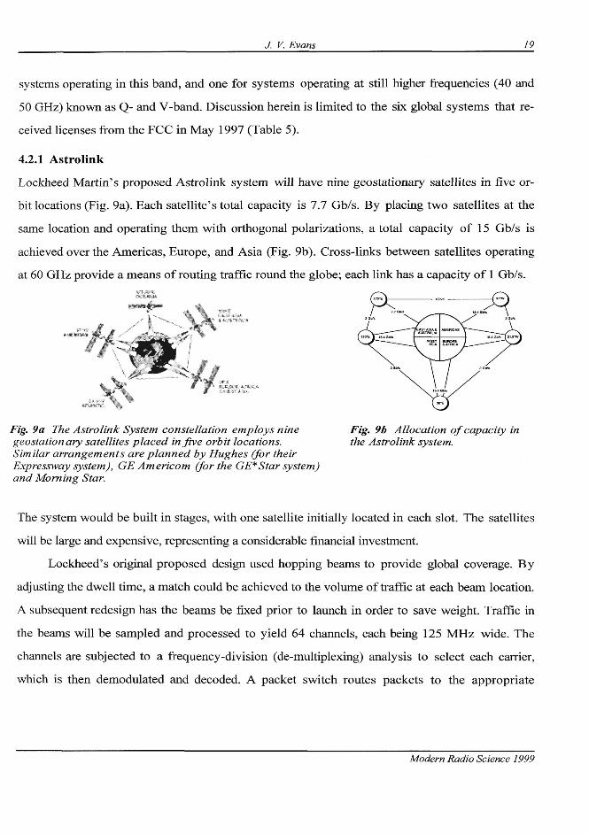
Fig. 9a The Astrolink System constellation employs ninegeostationary satellites placed in five orbit locations.Similar arrangements are planned by Hughes (for theirExpressway system), GE Americom (for the GE*Star system)and Morning Star.
Fig. 9b Allocation of capacity inthe Astrolink system.
The system would be built in stages, with one satellite initially located in each slot. The satellites
will be large and expensive, representing a considerable financial investment.
Lockheed's original proposed design used hopping beams to provide global coverage. By
adjusting the dwell time, a match could be achieved to the volume of traffic at each beam location.
A subsequent redesign has the beams be fixed prior to launch in order to save weight. Traffic in
the beams will be sampled and processed to yield 64 channels, each being 125 MHz wide. The
channels are subjected to a frequency-division (de-multiplexing) analysis to select each carrier,
which is then demodulated and decoded. A packet switch routes packets to the appropriate
Modern Radio Science 1999
systems operating in this band, and one for systems operating at still higher frequencies (40 and
50 GHz) known as Q- and V-band. Discussion herein is limited to the six global systems that re-
ceived licenses from the FCC in May 1997 (Table 5).
4.2.1 Astrolink
Lockheed Martin's proposed Astrolink system will have nine geostationary satellites in five or-
bit locations (Fig. 9a). Each satellite's total capacity is 7.7 Gb/s. By placing two satellites at the
same location and operating them with orthogonal polarizations, a total capacity of 15 Gb/s is
achieved over the Americas, Europe, and Asia (Fig. 9b). Cross-links between satellites operating
at 60 GHz provide a means of routing traffic round the globe; each link has a capacity of 1 Gb/s.
s - . ; ^* ! . % • ' * > - . -
• • .
. 1 / .
; G n
acre
tMERCAS
^ fiFRCA
2 GIVE.- au
15.4 Gb*
20 J. V. Evans
downlink channel, where they are multiplexed with other packets destined for the same beam, re-
encoded, and modulated onto the carrier.
Astrolink proposes to equip users with terminals employing antennas of 65, 85, and 120
cm in diameter, operating at power levels ranging from 0.25 to 10.0 W, at rates in the range of 64
kb/s to 8.448 Mb/s (with larger antennas and higher powers being required for the higher rates.)
These terminals would interconnect with the terrestrial switched network via gateway stations
employing 2.4- or 4.5-m antennas with up to 200 W of power.
4.2.2 Cyberstar
Loral's proposed Cyberstar system represents a lower cost, less risky approach to the market.
Loral proposes to launch just three geostationary satellites positioned to reach the world's largest
population centers and has been awarded slots at 28°E, 105.5°E, and 115°W. The satellites were
to employ multiple spot beams interconnected by an on-board processor, but the plans appear
have undergone several changes. For a while Loral pursued a simpler design (Phase 1) that en-
tailed no onboard processor, allowing very early entry to the market. In Phase 2, three larger,
more powerful satellites were to be launched, each with a total capacity of 10 Gb/s and capable
of providing beam-to-beam connectivity via an onboard processor. At last report, Loral appeared
to be reevaluating this plan in favor of going directly to the Phase 2 system. For the moment, Lo-
ral seems intent on developing an interim service capability (called Cyberlink) with the assets it
obtained from AT&T Skynet and Orion.
4.2.3 Galaxy/Spaceway
Hughes' proposed geostationary satellite system called Galaxy/Spaceway would have 21 satel-
lites in 16 orbital locations. The Spaceway™ portion of this system resembles that proposed by
Lockheed Martin for Astrolink (Fig. 9a) in that it consists of nine satellites placed in five orbital
locations, with intersatellite links between four of the locations.
In the system's Spaceway™ portion, two satellites will occupy each of four orbit loca-
tions. By operating each satellite over the allowed 500 MHz of spectrum (but with different po-
larizations), an equivalent of 1,000 MHz of bandwidth is obtained. Each satellite supports 68
transponders, 64 which occupy 125 MHz each (for the users), and two which occupy 250 MHz
Modern Radio Science 1999

J. V. Evans 21
(for gateways), thus achieving further frequency reuse. The transponders operate into narrow
(59-dBW EIRP) and wide (52.3-dBW EIRP) spot beams that cover the land masses visible to the
satellites. The intersatellite links operate at 60 GHz and have a 1 Gb/s data rate. Communications
services will be provided at rates of 16 kb/s to 1.544 Mb/s via terminals with antennas in the
range of 66 to 200 cm in diameter and uplink transmitters of up to 2 W. Onboard processing of
arriving packets is employed, both to route traffic between beams and to merge traffic in a given
transponder into a single 92-Mb/s stream.
4.2.4 GE* Star
GE American Communications, Inc. (GE Americom) proposed a system of nine geostationary
satellites occupying five orbits (GE*Star). The system's satellites will produce 44 spot beams
each for transmitting and receiving and operate in a fourfold frequency reuse pattern. Signals re-
ceived in these beams will be separated by filters into six 24-MHz sub-bands for high-traffic re-
gions (24 beams) and three 24 MHz sub-bands in low-traffic regions (20 beams). The 204 sub-
bands are processed at base-band to recover the digital bit streams, which are routed to a down-
link beam. The downlink beams would operate at 40 Mb/s, with an EIRP at beam center of 54 or
51 dBW for the high- and low-traffic regions, respectively.
GE Americom intends to work with manufacturers so that terminals are produced that are
compatible with its system. The terminals' proposed antenna sizes are 75 and 150 cm, operating
at 1 W achieving rates of 384 kb/s and 1.544 Mb/s, respectively. Rather than award its satellite
construction contract to a potential competitor (Hughes, Lockheed Martin or Loral), GE Ameri-
com has announced that they will be built by the Harris Corporation.
4.2.5 Morning Star
The Morning Star Satellite Company, L.L.C., of Washington, D.C., has proposed a system of
four geostationary satellites designed to serve parts of North America, Europe, and Asia. Like the
Hughes' Galaxy proposal, Morning Star proposed using hybrid Ku/Ka-band satellites, but has
been authorized to proceed only with the Ka-band portion. As originally proposed, each satellite
would employ up to 10 receive spot beams operating at 30 GHz and combine their traffic into a
single 20-GHz downlink beam to a gateway earth station. This station would uplink signals at 30
Modern Radio Science 1999

22 J. V. Evans
GHz that would be separated and transmitted via the spot beams at 12 GHz (Ku-band). Since
the use of the Ku-band was not authorized, this arrangement will have to be modified
The satellites employ simple frequency-translating transponders with no onboard proc-
essing. This, together with the absence of frequency reuse, limits their capacity to 0.7 Gb/s. The
design is unique among those proposed in that beam-to-beam connectivity can be provided, but
requires two transmissions through the satellite (a so-called double hop). This is wasteful of sat-
ellite resources, but presumably Morning Star plans mainly to deliver movies and Internet serv-
ice, both of which would originate at the gateway earth stations.
4.2.6 Teledesic
The Teledesic system has been described in numerous technical papers, but now appears to be
undergoing complete redesign. As first conceived, a LEO system was chosen because very large
data rates were incompatible with the delay (or latency) encountered with geostationary dis-
tances. Also, to mitigate rain fading, each satellite's service area was limited to a cone of ±40°
about the nadir (i.e., subsatellite point). This (together with the low altitude chosen) brought the
number of satellites needed for global coverage to 840. Each satellite in the system was capable of
cross-linking with its eight nearest neighbors and employed phased array antennas to scan "cells"
on the ground from which to collect and deliver traffic.
Teledesic has announced that the satellite number is to be reduced to 288 and the orbit
raised to 1,400 km. The parameters given in Table 5 are for the old design. Details of the new one
are unavailable, and little more can be said about this system. Teledesic probably remains the
most advanced of all of the proposed systems, and with 288 satellites is likely to be the most ex-
pensive. Given that Motorola has elected to join the Teledesic project and will be technical man-
ager, further changes to the design and/or number of satellites are probable in order to reduce capi-
tal outlay and increase the chances of financing the system.
5. Concluding Remarks
Satellite projects are enjoying a period of great interest, spurred by a number of factors. The
overall telecommunications market is growing rapidly, due in part to growth in international
Modern Radio Science 1999

J. V. Evans 23
trade, but also due to reduced prices for many services and the introduction of new services (such
as cellular or PCS and Internet access). Deregulation and the opening of overseas markets offer
new opportunities for telecommunications companies. Satellites can provide almost "instant" in-
frastructure, requiring little in the way of the civil works needed to install other systems. In addi-
tion, U.S. aerospace companies are seeking new opportunities in the civil sector now that defense
orders have declined. Lockheed Martin, Loral, and Motorola appear intent on vertically inte-
grating into the service business, as Hughes has successfully done. Finally, there is a realization
that the resources (frequencies and geostationary orbital slots) available for satellite projects are
quite limited. The FCC's Ka-band rule-making probably represented one of the last opportuni-
ties to lay claim to a limited resource.
Over the long term, communications satellites will be used only when they provide a clear
competitive advantage. These situations include broadcasting, distributing the same information
(e.g., television) to a large number of subscribers (such as schools or cable head ends), and mobile
applications (ships, planes, travelers in remote places, etc.).
If some of the Ka-band systems described here are successful, then satellites may enjoy a
role not heretofore theirs—providing "last mile" connections to homes and businesses for
broadband data, multimedia, and related services. Success here depends critically on bringing
down user terminal costs; this can be achieved only if terminals are mass-produced using spe-
cially developed chip sets for all functions. Since it will be particularly difficult to lower the price
of terminals requiring tracking antennas, it seems that the LEO systems will have greater diffi-
culty serving the consumer market. Also, timing is critical, since other technologies for wideband
Internet access are being pursued in the developed countries where the largest markets are ini-
tially to be found.
Satellites will also continue to be used for the foreseeable future to deliver telephony and
other public switched services to countries that are not linked by fiber optic cables, and to sup-
port private (e.g., VSAT) networks that cover a wide geographic area. However, these roles ap-
pear inadequate to justify all of the current interest in new satellite systems.
Modern Radio Science 1999


![Polymer Brushes: On the Way to Tailor-Made Surfacescatalogimages.wiley.com/images/db/pdf/3527310339.excerpt.pdf · brushes”[10].Polymerbrushesareveryinterestingsystems,asthestrongstretching](https://img.pdfslide.us/doc/110x75/5b89597e7f8b9a851a8d6d65/polymer-brushes-on-the-way-to-tailor-made-s-brushes10polymerbrushesareveryinterestingsystemsasthestrongstretching.jpg)