Embed Size (px)
Citation preview
THE PALEOINDIAN FLUTED POINT: DART OR SPEAR ARMATURE?
THE IDENTIFICATION OF PALEOINDIAN DELIVERY TECHNOLOGY
THROUGH THE ANALYSIS OF LITHIC FRACTURE VELOCITY
BY
Wallace Karl Hutchings
B.A., Simon Fraser University, 1987
M.A., University of Toronto, 1991
THESIS SUBMITTED IN PARTIAL FULFILLMENT OF
THE REQUIREMENTS FOR THE DEGREE OF
DOCTOR OF PHILOSOPHY
in the Department
of
Archaeology
O Wallace Karl Hutchings 1997
SIMON FRASER UNIVERSITY
November, 1997
All rights reserved. This work may not be reproduced in whole or in part, by photocopy
or other means, without permission of the author.
National bbrary I*I of Canada BiblioMque nationale du Canada
Acquisitions and Acquisitions 81 Bbliographic ~ e d i c e s services bibliographiques
395 Wdllngton Street 3%. sue Welllngtor? CXtawaON K l A O N 4 OfiawaON K l A O N 4 ,
Canada Canada
The author has granted a non- exclusive licence allowing the National Library of Canada. to , reproduce, loan, dstribute or sell copies of t h s thesis in microform, paper or electromc formats.
.. The author retams ownership of the copyright in thls thesis. Neither the thgsis nor substanhal extracts from it may be printed or otherwise reproduced without the author' s permission.
L'auteur a accord& une licence non exclusive pernettant a la Bibliotheque nationale du Canada de regroduire, prster, dstnbuer ou vendre des copies de cette these sous la forme de microfiche/film, de reproduction sur papier - ou sur format electso~que. I
L'auteur conserve la' propnete du droit d'auteur qui protege cette these. <Ni la these 111 des extraits substantiels de celle-ci ne doivent @tre imprimes ou autrement reproduits sans son autorisation.
</ f'
. Approval
NAME: W. Karl Hutchings
DEGREE: PhD. 4
'Kr'LE OF THESIS: The Paleoindian Fluted Point: b u t or Spear Armature? The Identification of Paleoindian Delivery Technology Through the Analysis of Lithic Fracture Velocity
EXAMINING COMMITTEE: 6
.Chair: Phil Hobler
Roy ~arl'son Senior Supervisor Professor Emeritus
Jack bance Professerf
Date Approved:
Dave Burley Professor
J.D. Speth External Examiner Department of Anthropology University of Michigan
October 31,1997
ABSTRACT
One of the highest-profile, yet least known peoples in New World archaeology, are
the Paleoindians. Despite the absence of supportive empirical data, archaeologists have
long assumed that Paleoindians employed the spearthrower along with heavy, fluted-
point-tipped darts, to hunt now extinct species of late Pleistocene mammoth and bison.
This assumption is critical to our understanding of Paleoindian life-ways since the
identification of exploitative technology, such as weapons systems, is often the first
crucial step towards the interpretation of higher order information that contributes to our
knowledge of prehistoric peoples. Without an accurate assessment of the basic tools with
which people interacted with their environment, we cannot fully explore more complex
issues such as technological and social organization, or settlement and subsistence
strategies.
Traditional analyses of weapon technologies generally rely on classification
schemes to identify projectile points as spear, dart, javelin, or arrow armatures. The
logical fallacy of such schemes is the assumption that the investigator knows, apriori,
that the artifact in question served as a projectile armature. By adopting and applying a
methodology based on the fracture mechanics of brittle solids, this research avoids such
interpretive leaps of faith.
Employing data derived from velocity-dependant micro-fracture features, a series of
controlled experiments were conducted to explore the range of lithic fracture velocities
associated with various manufacturing (reduction) techniques, projectile impacts, and
accidental breakage. Manufacturing and weapon delivery technologies are differentiated
based on the fracture velocity exhibited by damaged artifacts; high-speed projectile
impacts are reliably distinguished from other sources of lithic fracture, thus providing a
quantitative means for identifying projectile armatures. Data derived from Paleoindian
artifacts reveal fracture rates associated with high-velocity impacts, indicating the use of
the spearthrower.
ACKNOWLEDGMENTS
This research was supported in part by a Simon Fraser University Doctoral Fellowship
(1 99 1, 1992, 1994, 1 W6), a President's Ph.D. Research Stipend (SFU) (1 999, and a
graduate research travel grant from the Department of Archaeology (SFU) (1 995).
Many individuals contributed their time, energy, and assistance in various forms
throughout this research. I especially thank Earl Hall and Brian McConaghy of the
R.C.M.P. Forensic Laboratory (Vancouver) - Firearms Section; Tom Troczynski and
Florin Esanu of the Department of Metals and Materials Engineering, University of
British Columbia, and Larry Courchaine of Checkmate Archery (Abbottsford). Thanks
also to Lorenz Briichert for endless ethnographic data concerning the spearthrower. I am
indebted to Berkley B. Bailey for providing geological samples from numerous Great
Plains Paleoindian tool-stone sources.
The collection of data from institutions in Canada and the United States would not
have been possible without the generous help of numerous people. I thank Mike Jacobs
of the Arizona State Museum; Vance Haynes of the Department of Anthropology,
University of Arizona; Bruce Huckell, Marianne Rodee, and Bobbi Hohman of the
Maxwell Museum, University of New Mexico; Patricia Nietfeld of the Museum of New
Mexico; James Dixon of the Denver Museum of Natural History; Jack Brink, and Bob
Dawe of the Provincial Museum of Alberta; Don Tuohy, and Sue Ann Monteleone of the
Nevada State Museum; Ken Hedges of the San Diego Museum of Man; John Fagan of
Archaeological Investigations Northwest (Portland); Melvin Aikens and Pam Endsweig
of the Oregon State Museum of Anthropology; and Elise V. LeCompte and David Webb
of the Florida Museum of Natural History, for all the help they have provided me in this
effort.
I owe special thanks to Tony and Simone Baker, who not only provided access to
their private collection, but extended the hospitality of their home during my visit to
Denver.
I express my sincere gratitude to the members of my supervisory committee, my
senior supervisor Dr. Roy Carlson, and Dr. Jack Nance, for their support and guidance.
Among the faculty of the Simon Fraser University Department of Archaeology, I also
wish to thank Dr. David Burley for his constructive criticism as a member of my thesis
examination committee, and Dr. Brian Hayden for the use of various microscopy
equipment. I am delighted to have a newfoGd friend in Dr. John D. Speth (Professor of
Anthropology, and Director of the Museum of Archaeology, University of Michigan [Ann
Arbor]), who served as my external thesis examiner. His extensive comments and
suggestions have contributed immensely to the clarity of this thesis, though ultimately,
any shortcomings are my sole responsibility.
Finally, but most of all, the tremendous support provided by my wife, Lisa, and my
parents, Wallace and Lillian, has been instrumental to my completion of this dissertation.
I thank them from the bottom of my heart.
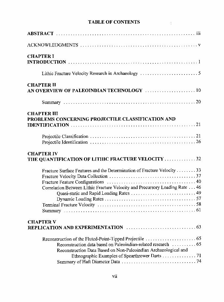
TABLE OF CONTENTS
... ABSTRACT . . . . . . . . . . . . . . . . . . . . . . . . . . . . . . . . . . . . . . . . . . . . . . . . . . . . . . . . . . ill
ACKNOWLEDGMENTS . . . . . . . . . . . . . . . . . . . . . . . . . . . . . . . . . . . . . . . . . . . . . . . . . v
CHAPTER I . . . . . . . . . . . . . . . . . . . . . . . . . . . . . . . . . . . . . . . . . . . . . . . . . . . . . . INTRODUCTION 1
. . . . . . . . . . . . . . . . . . . . . . . . Lithic Fracture Velocity Research in Archaeology 5
CHAPTER I1 . . . . . . . . . . . . . . . . . . . . . AN OVERVIEW OF PALEOINDIAN TECHNOLOGY 10
Summary . . . . . . . . . . . . . . . . . . . . . . . . . . . . . . . . . . . . . . . . . . . . . . . . . . . . . . . 20
CHAPTER I11 PROBLEMS CONCERNING PROJECTILE CLASSIFICATION AND IDENTIFICATION . . . . . . . . . . . . . . . . . . . . . . . . . . . . . . . . . . . . . . . . . . . . . . . . . . . . 21
. . . . . . . . . . . . . . . . . . . . . . . . . . . . . . . . . . . . . . . . . . . . Projectile Classification 21
. . . . . . . . . . . . . . . . . . . . . . . . . . . . . . . . . . . . . . . . . . . . Projectile Identification 26
CHAPTER IV . . . . . . . . . . . . . THE QUANTIFICATION OF LITHIC FRACTURE VELOCITY 32
Fracture Surface Features and the Determination of Fracture Velocity . . . . . . . . 33 . . . . . . . . . . . . . . . . . . . . . . . . . . . . . . . . . . . . Fracture Velocity Data Collection 37
. . . . . . . . . . . . . . . . . . . . . . . . . . . . . . . . . . . . . Fracture Feature Configurations 40 Correlation Between Lithic Fracture Velocity and Precursory Loading Rate . . . 46
. . . . . . . . . . . . . . . . . . . . . . . . . . . Quasi-static and Rapid Loading Rates 49 . . . . . . . . . . . . . . . . . . . . . . . . . . . . . . . . . . . . . . Dynamic Loading Rates 57
. . . . . . . . . . . . . . . . . . . . . . . . . . . . . . . . . . . . . . . . . Terminal Fracture Velocity 58 Summary . . . . . . . . . . . . . . . . . . . . . . . . . . . . . . . . . . . . . . . . . . . . . . . . . . . . . . . 61
CHAPTER V . . . . . . . . . . . . . . . . . . . . . . . . . . . . . REPLICATION AND EXPERIMENTATION 63
. . . . . . . . . . . . . . . . . . . . . Reconstruction of the Fluted-Point-Tipped Projectile 65 Reconstruction data based on Paleoindian-related research . . . . . . . . . . 65 Reconstruction Data Based on Non-Paleoindian Archaeological and
Ethnographic Examples of Spearthrower Darts . . . . . . . . . . . . . . 71 . . . . . . . . . . . . . . . . . . . . . . . . . . . . . . . Summary of Haft Diameter Data 74
vii
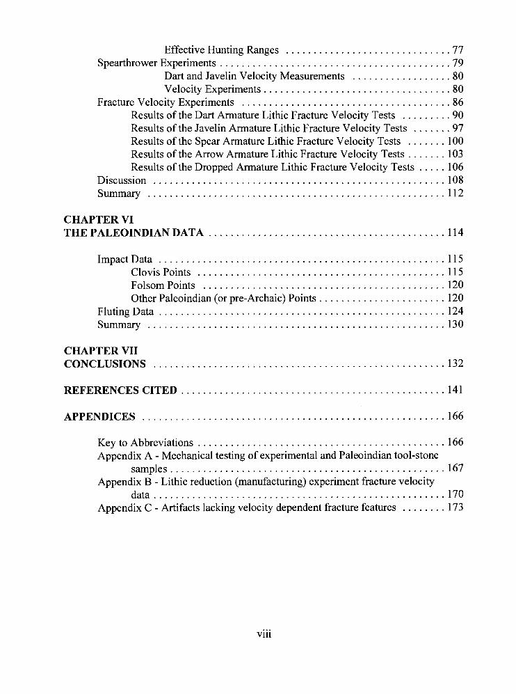
Effective Hunting Ranges . . . . . . . . . . . . . . . . . . . . . . . . . . . . . . 77 Spearthrower Experiments . . . . . . . . . . . . . . . . . . . . . . . . . . . . . . . . . . . . . . . . . . 79
Dart and Javelin Velocity Measurements . . . . . . . . . . . . . . . . . . 80 Velocity Experiments . . . . . . . . . . . . . . . . . . . . . . . . . . . . . . . . . . 80
Fracture Velocity Experiments . . . . . . . . . . . . . . . . . . . . . . . . . . . . . . . . . . . . . . 86 Results of the Dart Armature Lithic Fracture Velocity Tests . . . . . . . . . 90 Results of the Javelin Armature Lithic Fracture Velocity Tests . . . . . . . 97 Results of the Spear Armature Lithic Fracture Velocity Tests . . . . . . . 100 Results of the Arrow Armature Lithic Fracture Velocity Tests . . . . . . . 103 Results of the Dropped Armature Lithic Fracture Velocity Tests . . . . . 106
Discussion . . . . . . . . . . . . . . . . . . . . . . . . . . . . . . . . . . . . . . . . . . . . . . . . . . . . . 108 Summary . . . . . . . . . . . . . . . . . . . . . . . . . . . . . . . . . . . . . . . . . . . . . . . . . . . . . . 112
CHAPTER VI . . . . . . . . . . . . . . . . . . . . . . . . . . . . . . . . . . . . . . . . . . . THE PALEOINDIAN DATA 114
ImpactData . . . . . . . . . . . . . . . . . . . . . . . . . . . . . . . . . . . . . . . . . . . . . . . . . . . . 115 . . . . . . . . . . . . . . . . . . . . . . . . . . . . . . . . . . . . . . . . . . . . . ClovisPoints 115
Folsom Points . . . . . . . . . . . . . . . . . . . . . . . . . . . . . . . . . . . . . . . . . . . . 120 Other Paleoindian (or pre-Archaic) Points . . . . . . . . . . . . . . . . . . . . . . . 120
FlutingData . . . . . . . . . . . . . . . . . . . . . . . . . . . . . . . . . . . . . . . . . . . . . . . . . . . . 124 Summary . . . . . . . . . . . . . . . . . . . . . . . . . . . . . . . . . . . . . . . . . . . . . . . . . . . . . . 130
CHAPTER VII CONCLUSIONS . . . . . . . . . . . . . . . . . . . . . . . . . . . . . . . . . . . . . . . . . . . . . . . . . . . . . 132
REFERENCESCITED . . . . . . . . . . . . . . . . . . . . . . . . . . . . . . . . . . . . . . . . . . . . . . . . 141
APPENDICES . . . . . . . . . . . . . . . . . . . . . . . . . . . . . . . . . . . . . . . . . . . . . . . . . . . . . . . 166
. . . . . . . . . . . . . . . . . . . . . . . . . . . . . . . . . . . . . . . . . . . . . Key to Abbreviations 166 Appendix A . Mechanical testing of experimental and Paleoindian tool-stone
samples . . . . . . . . . . . . . . . . . . . . . . . . . . . . . . . . . . . . . . . . . . . . . . . . . . 167 Appendix B . Lithic reduction (manufacturing) experiment fracture velocity
data . . . . . . . . . . . . . . . . . . . . . . . . . . . . . . . . . . . . . . . . . . . . . . . . . . . . . 170 Appendix C . Artifacts lacking velocity dependent fracture features . . . . . . . . 173
... Vl l l
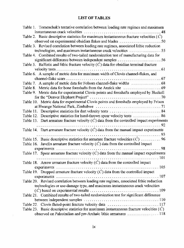
LIST OF TABLES
Table 1 . Tomenchuk's tentative correlation between loading rate regimes and maximum instantaneous crack velocities . . . . . . . . . . . . . . . . . . . . . . . . . . . . . . . . . . . . . . . 48
Table 2 . Basic descriptive statistics for maximum instantaneous fracture velocities ( 6 ) observed on experimental obsidian flakes and blades . . . . . . . . . . . . . . . . . . . . . 50
Table 3 . Revised correlation between loading rate regimes, associated lithic reduction technologies. and maximum instantaneous crack velocities . . . . . . . . . . . . . . . . 55
Table 4 . Combined results of two-tailed randomization test of manufacturing data for significant difference between independent samples . . . . . . . . . . . . . . . . . . . . . . 56
Table 5 . Ballistic and lithic fracture velocity ( 6 ) data for obsidian terminal fracture velocitytests . . . . . . . . . . . . . . . . . . . . . . . . . . . . . . . . . . . . . . . . . . . . . . . . . . . . . 61
Table 6 . A sample of metric data for maximum width of Clovis channel-flakes, and channel-flakescars . . . . . . . . . . . . . . . . . . . . . . . . . . . . . . . . . . . . . . . . . . . . . . . . 67
Table 7 . A sample of metric data for Folsom channel-flake widths . . . . . . . . . . . . . . . 68 Table 8 . Metric data for bone foreshafts from the Anzick site . . . . . . . . . . . . . . . . . . . 69 Table 9 . Metric data for experimental Clovis points and foreshafts employed by Huckell
for the "Denver Elephant Project" . . . . . . . . . . . . . . . . . . . . . . . . . . . . . . . . . . . . 70 Table 10 . Metric data for experimental Clovis points and foreshafts employed by Frison
at Hwange National Park, Zimbabwe . . . . . . . . . . . . . . . . . . . . . . . . . . . . . . . . . 71 . . . . . . . . . . . . . . . . . . . . . . . . . . Table 1 1 . Descriptive statistics for dart velocity tests 84
Table 12 . Descriptive statistics for hand-thrown spear velocity tests . . . . . . . . . . . . . . 86 Table 13 . Dart armature fracture velocity ( 6 ) data from the controlled impact experiments
. . . . . . . . . . . . . . . . . . . . . . . . . . . . . . . . . . . . . . . . . . . . . . . . . . . . . . . . . . . . . . . 92 Table 14 . Dart armature fracture velocity (c) data from the manual impact experiments
. . . . . . . . . . . . . . . . . . . . . . . . . . . . . . . . . . . . . . . . . . . . . . . . . . . . . . . . . . . . . . . 93 Table 15 . Basic descriptive statistics for armature fracture velocities ( 6 ) . . . . . . . . . . 96 Table 16 . Javelin armature fracture velocity ( 6 ) data from the controlled impact
experiments . . . . . . . . . . . . . . . . . . . . . . . . . . . . . . . . . . . . . . . . . . . . . . . . . . . . . 98 Table 17 . Spear armature fracture velocity ( 6 ) data from the manual impact experiments
. . . . . . . . . . . . . . . . . . . . . . . . . . . . . . . . . . . . . . . . . . . . . . . . . . . . . . . . . . . . . . 101 Table 18 . Arrow armature fracture velocity ( 6 ) data from the controlled impact
experiments . . . . . . . . . . . . . . . . . . . . . . . . . . . . . . . . . . . . . . . . . . . . . . . . . . . . 105 Table 19 . Dropped armature fracture velocity ( 6 ) data from the controlled impact
experiments . . . . . . . . . . . . . . . . . . . . . . . . . . . . . . . . . . . . . . . . . . . . . . . . . . . . 107 Table 20 . Revised correlation between loading rate regimes. associated lithic reduction
technologies or use-damage type. and maximum instantaneous crack velocities ( C) based on experimental results . . . . . . . . . . . . . . . . . . . . . . . . . . . . . . . . . . . 109
Table 21 . Combined results of two-tailed randomization test for significant difference between independent samples . . . . . . . . . . . . . . . . . . . . . . . . . . . . . . . . . . . . . . 110
Table 22 . Clovis fluted-point fracture velocity data . . . . . . . . . . . . . . . . . . . . . . . . . . 117 Table 23 . Basic descriptive statistics for maximum instantaneous fracture velocities ( 6 )
observed on Paleoindian and pre-Archaic lithic armatures . . . . . . . . . . . . . . . . 118

. . . . . . . . . . . . . . . . . . . . . . . . . . Table 24 . Folsom fluted-point fracture velocity data 122 Table 25 . Other Paleoindian (or pre-Archaic) point fracture velocity data . . . . . . . . . 123 Table 26 . Clovis flute fracture velocity data . . . . . . . . . . . . . . . . . . . . . . . . . . . . . . . . 128
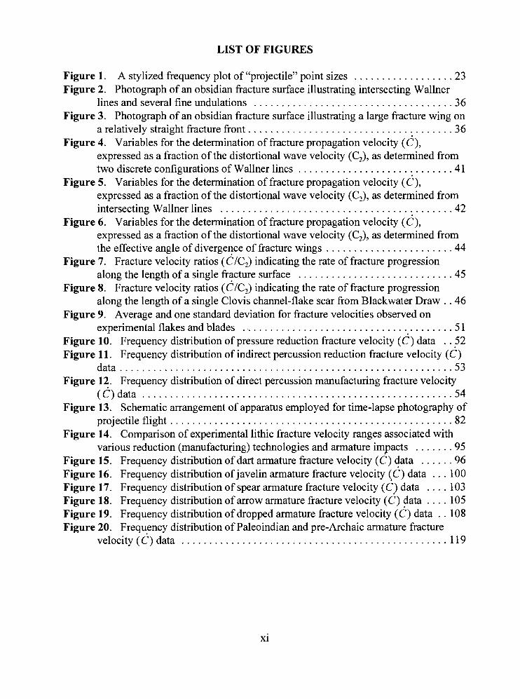
LIST OF FIGURES
Figure 1. A stylized frequency plot of "projectile" point sizes . . . . . . . . . . . . . . . . . . 23 Figure 2. Photograph of an obsidian fracture surface illustrating intersecting Wallner
lines and several fine undulations . . . . . . . . . . . . . . . . . . . . . . . . . . . . . . . . . . . . 36 Figure 3. Photograph of an obsidian fracture surface illustrating a large fracture wing on
a relatively straight fracture front . . . . . . . . . . . . . . . . . . . . . . . . . . . . . . . . . . . . . 36 Figure 4. Variables for the determination of fracture propagation velocity (c),
expressed as a fraction of the distortional wave velocity (C,), as determined from two discrete configurations of Wallner lines . . . . . . . . . . . . . . . . . . . . . . . . . . . .41
Figure 5. Variables for the determination of fracture propagation velocity (c), expressed as a fraction of the distortional wave velocity (C,), as determined from intersecting Wallner lines . . . . . . . . . . . . . . . . . . . . . . . . . . . . . . . . . . . . . . . . . . 42
Figure 6. Variables for the determination of fracture propagation velocity (c), expressed as a fraction of the distortional wave velocity (C,), as determined from the effective angle of divergence of fracture wings . . . . . . . . . . . . . . . . . . . . . . . 44
Figure 7. Fracture velocity ratios ( d l ~ , ) indicating the rate of fracture progression along the length of a single fracture surface . . . . . . . . . . . . . . . . . . . . . . . . . . . .45
Figure 8. Fracture velocity ratios (CIC,) indicating the rate of fracture progression along the length of a single Clovis channel-flake scar from Blackwater Draw . . 46
Figure 9. Average and one standard deviation for fracture velocities observed on experimental flakes and blades . . . . . . . . . . . . . . . . . . . . . . . . . . . . . . . . . . . . . . 5 1
Figure 10. Frequency distribution of pressure reduction fracture velocity (c) data . . 52 Figure 11. Frequency distribution of indirect percussion reduction fracture velocity ( d )
data . . . . . . . . . . . . . . . . . . . . . . . . . . . . . . . . . . . . . . . . . . . . . . . . . . . . . . . . . . . . 53 Figure 12. Frequency distribution of direct percussion manufacturing fracture velocity
(C)data . . . . . . . . . . . . . . . . . . . . . . . . . . . . . . . . . . . . . . . . . . . . . . . . . . . . . . . . 54 Figure 13. Schematic arrangement of apparatus employed for time-lapse photography of
projectile flight . . . . . . . . . . . . . . . . . . . . . . . . . . . . . . . . . . . . . . . . . . . . . . . . . . . 82 Figure 14. Comparison of experimental lithic fracture velocity ranges associated with
various reduction (manufacturing) technologies and armature impacts . . . . . . . 95 Figure 15. Frequency distribution of dart armature fracture velocity (C) data . . . . . . 96 Figure 16. Frequency distribution of javelin armature fracture velocity ( 6 ) data . . . 100 Figure 17. Frequency distribution of spear armature fracture velocity ( 6 ) data . . . . 103 Figure 18. Frequency distribution of arrow armature fracture velocity (c) data . . . . 105 Figure 19. Frequency distribution of dropped armature fracture velocity ( 6 ) data . . 108 Figure 20. Frequency distribution of Paleoindian and pre-Archaic armature fracture
velocity(C)data . . . . . . . . . . . . . . . . . . . . . . . . . . . . . . . . . . . . . . . . . . . . . . . . 119
CHAPTER I
INTRODUCTION
"Archaeology is rather like a vast, fiendish jigsaw puzzle . . . ." - Paul Bahn -
Since the initial discovery of stone tools in association with extinct Pleistocene
fauna at Folsom, New Mexico in 1926 (Figgens 1 927), Paleoindian cultures have been at
the forefront of American archaeology. At present, the earliest, undisputed, clearly
defined cultural complex in the New World is that of the Clovis people (Haynes
1993 :2 19), named for the type site of Blackwater Draw near Clovis, New Mexico (Hester,
Lundelius, and Fryxell 1972; Sellards 1952).
By the early 19801s, Clovis assemblages had been documented throughout most of
the North American continent. Although sharing broad similarities in tool kits and site
types, these widespread assemblages are now known to exhibit variations in regional
point morphology, environmental settings, economies, and occupation dates (Willig
1991).
Johnson (1 991) states that the fluted point was the focus of the Clovis tool kit.
While this may have been true prehistorically, there is no doubt that it is the focus of
modem archaeological investigations. More than any other New World culture, the
Clovis complex has been defined by this one artifact form, and despite apparent regional
economic differentiation, the fluted Clovis point has come to signify late-Pleistocene,
mammoth-hunting Paleoindians.
1
2
The concept of the Llano-Clovis big-game hunting tradition grew out of the
repeated association of Clovis cultural materials with the remains of extinct megafauna at
well-dated kill sites in the Southwest and on the Plains. There is no doubt that fluted
points were used to dispatch late-Pleistocene megafauna. Rather, the question is: how
were these points used to bring down such large game? Some researchers have suggested
alternative hunting strategies including the use of trapping areas, dead falls, snares,
mechanical traps, and pits (e.g., Frison 1991; Haynes 1980; Johnson, Kawano, and Ekker
1980). Few have devoted much attention to the weaponry per se, apart from empirical
descriptions of the points themselves or discussions of metric and stylistic variation.
It is generally accepted that fluted points functioned primarily as spear armatures,
and perhaps secondarily as knives or butchery tools. There is no concrete empirical
evidence which can provide us with a complete picture of such a weapon or tool since no
hafted fluted points have been recovered to date. A common reconstruction of
Paleoindian weaponry suggests that the spear was propelled by use of a spearthrower
(e.g., Amick 1996:414; Fagan l987:180-181, Frison 1989:766), a device which allows
spears (properly referred to as "darts" when associated with the spearthrower) to be
launched with greater speed and a flatter trajectory than a hand-thrown spear.
The spearthrower is a device with considerable antiquity in the Old World, in use
since at least the Magdalenian of Upper Paleolithic Europe approximately 17,000 years
ago, and perhaps much earlier (cf., Caton-Thompson 1946; Knecht 1994). It is known
from the circumpolar regions, western Europe, and throughout most of North America,
Central and South America, Australia, Melanesia, and Micronesia. While there is no
reason to assume that migrants to the New World could not have possessed the device,
there currently is no empirical evidence that it was used by the earliest New World
hunters.
Despite this, students of archaeology are exposed to illustrations in introductory
textbooks of Paleoindians employing the spearthrower to launch fluted-point tipped darts
(e.g., Fagan 1987: 180-181), and even a PBS program that features a prominent
Paleoindian archaeologist demonstrating the effectiveness of Clovis spearthrowers (Eder
1988).
Experiments designed to test the performance capabilities of Clovis weaponry have
been conducted on elephant carcasses, and may have served to perpetuate the image
among academics (Frison 1989; Huckell 1982). References to Paleoindian
spearthrowers (most often referred to by the Nahua term "atlatl") are common in the
academic literature, as illustrated in the following statements:
The association of Clovis type projectile points and mammoth remains in archaeological sites . . . has convinced most Paleoindian investigators that the Clovis projectile point used on a thrusting spear and/or with atlatl and dart was the weaponry used to kill the mammoths [Frison 1989:766].
Most of the [Folsom] projectile points recorded are fragments, presumably broken on impact during use as atlatl dart tips [Amick 1996:4 141.
Notably, these, and similar statements offer no empirical evidence for the existence
of the spearthrower during the Paleoindian period, and offer no references to the origin of
the spearthrower hypothesis. It is not difficult to understand why many people assume
that Paleoindians possessed this type of weaponry. The range and power advantage
provided by the spearthrower (Hutchings and Briichert 1997), relative to the thrusting-
4
spear and javelin, make it is easy to speculate that Paleoindian hunters needed as much
"firepower" as possible to successfully penetrate the armoured hides of six to eight-ton
mammoths.
Opponents to the Clovis spearthrower hypothesis rely on normative arguments
based primarily on technological and morphological aspects of lithic point design.
Wright (1995:35), for example, argues that the spearthrower is associated with notched
points, and has created a model that traces the diffusion of the spearthrower from a source
in the Archaic Southeast. Also relying on the interpretation of hafting technology,
Gramley (1 984) cites flute widths as evidence that Clovis points were employed as
(thrusting-) spear armatures at the Vail site.
Evidence for the initial appearance of the spearthrower in the New World is
undeniably early. Cockrell and Murphy (1978; see also Royal and Clark 1960) report a
shell spearthrower hook, from Warm Mineral Springs, Florida, in association with human
remains, in deposits dated between approximately 9,000 and 10,000 years ago (see also
Clausen, Brooks, and Wesolowsky 1975). Other spearthrower hooks are reported from
the Windust Phase at Marmes Rockshelter in Washington (Rice 1972), dated between
approximately 9,000 and 10,000 years ago (Sheppard et al. 1987); from Fort Rock Cave,
Oregon, dated approximately 8,500 years ago (Cressman 1977: 105); and from the
Roadcut site at Five Mile Rapids, Oregon, dated between approximately 7,600 and 7,900
years ago (Cressman 1960:24, and Figures 20 and 40).
Heite and Blume (1995:53) report a slate "bannerstone" from deposits dating to
approximately 1 1,000 years ago at the Blueberry Hill site (Delaware). Although,
5
bannerstones are reputed to have functioned as spearthrower weights, their association
with the spearthrower has never been empirically demonstrated. The 0.9 cm diameter
groove in this slate object (Heite and Blurne 1995:Figure 28) suggests, however, that it is
probably a grooved and shaped abrader, possibly a shaft smoother.
One is forced to conclude, therefore, that the earliest empirical evidence for the use
of the spearthrower in the New World is currently represented by the spearthrower hooks
from Warm Mineral Springs, and Marrnes Rockshelter. The 9,000 to 10,000 year old
associated dates suggest that the spearthrower was in use by at least the Early Archaic
Period.
The intent of this research is to determine whether there is any empirical evidence
for earlier use of the spearthrower in the New World; specifically, whether Paleoindian
points were associated with the use of the spearthrower, or were restricted to hand-thrown
spears, thrusting spears, or any combined use of these systems. The emphasis is on
Clovis and Folsom fluted-points, but other early, pre-Archaic (as defined by Willig
[I 989: 13- 141) point types were examined for comparison purposes. The research
approach employs fracture velocity data derived from the damaged surfaces of these
artifacts.
Lithic Fracture Velocity Research in Archaeology
A number of researchers have been concerned with the mechanics of brittle fracture
in stone tool materials for several decades (e.g., Cotterell and Karnrninga 1979, 1987;
Faulkner 1972; Fonseca, Eshelby, and Atkinson 1971 ; Goodman 1944; Kerkhof and
6
Miiller-Beck 1969; Speth 1972, 1974, 1975, 198 1 ; Warren 19 14; and most recently
Tomenchuk 1985; Hutchings 1991). Most have been interested in the fracture process
per se from a technical and morphological standpoint; very few have directed their
attention towards the determination of fracture propagation velocity as an analytic tool
with broader implications.
Referring to certain microscopic ripple marks on the fracture surfaces of flakes and
blades, Faulkner (1 972: 162) stated a quarter-century ago that:
Gull [i.e., fracture] wings and Wallner lines, are indicators of fracture velocity, which may prove to be a diagnostic characteristic separating flakes produced at different loading speeds.
Similarly, Cotterell and Kamminga (1987:703) state that:
An appreciation of the mechanics of flake formation can lead directly to behavioral implications. For instance, with glassy stone like obsidian it is possible to distinguish flakes produced by pressure from those produced by percussion by calculating the crack velocity registered by Wallner lines.
Although both Faulkner, and Cotterell and Karnminga had alluded to archaeological
applications, it was Tomenchuk (1985) that first employed fracture velocity
determinations derived directly from archaeological materials for the investigation of
prehistoric human behaviour. His landmark development of a fracture mechanics-based
lithic use-wear-methodology required a non-subjective, quantitative method to determine
the precursory loading rate responsible for the use-damage exhibited by stone tools. His
force estimating models were applicable only to use-damage resulting from quasi-static
and rapid loading conditions (e.g., cutting, sawing, drilling, incising, scraping). Fracture
velocity determinations were, therefore, necessary to distinguish these from use-damage
7
resulting from dynamic loading conditions (e.g., chopping, projectile impacts, various
types of high energy percussion).
While the determination of lithic fracture velocity was not Tomenchuk7s (1 985)
central research concern, his exhaustive theoretical and methodological fracture
mechanics research paved the way for subsequent investigation. Research concerning
fracture velocity assessments of post-Natufian composite lithic armatures (Hutchings
1991), suggested that as the impact speeds (i.e., precursory loading rate) of projectile
armatures increased, fracture propagation velocities exhibited by the damaged lithic
components also increased. Since differing weapon technologies propel armatures at
different speeds, lithic fracture velocity data derived from damaged armatures should be a
useful indicator of the original weapon technology.
The current experimental program was designed to investigate whether weapon
technologies could be differentiated based on the fracture velocity exhibited by damaged
armatures. The research approach is one of replication and experimentation. Fracture
velocity data collected from replicated projectile armatures damaged during controlled
experimentation are compared with like data from archaeological specimens.
The archaeological sample is comprised of fluted Paleoindian, and non-fluted pre-
Archaic (as defined by Willig 1989: 13-14) bifacial points. The reader should keep in
mind that the goal of this research is to document fracture velocities associated with these
types of artifacts, and determine whether fracture velocity analysis may be used as a
reliable indicator of specific delivery technologies. The goal is not to demonstrate that
these artifacts represent the only lithic armatures employed by Paleoindian and pre-
8
Archaic peoples. In addition, while data are collected from damaged artifacts (i.e.,
fracture surfaces), there is no reason to assume apriori that a given fracture was the result
of use of any type. The experimental fracture velocity research presented in Chapter IV
provides the necessary framework to determine whether a given fracture could have
resulted from known reduction processes or incidental damage. Therefore the selection
of these artifacts, generally assumed to represent weapon armatures, in no way affirms the
consequence of the analysis.
An unfortunate fact of this type of research is the surficial appearance of a lack of
human focus. While the central concern is documentation of evidence which will
elucidate a vital aspect of Paleoindian life-ways, the analytic universe unavoidably
consists of technical items, rather than behavioral, organizational, or sociopolitical data.
The reasons for this approach are discussed in Chapter 111, where it is demonstrated that
archaeologists currently have no theoretically reliable means of identifying rudimentary
functional classifications for prehistoric weapon armatures. As a consequence,
archaeological analyses of hunter-gatherer lifeways based on the interpretation of basic
food-getting technology, where only the lithic armatures are represented, currently lack a
solid theoretical foundation.
The practical and methodological fracture mechanics background pertinent to this
research is discussed in Chapter IV. I recommend that readers interested in the history of
theoretical fracture mechanics, or discussions of other aspects of brittle fracture and wave
mechanics, consult Speth (1 972), and Tomenchuk (1 985).
Chapter V presents archaeological, ethno-historic, and experimental data concerning
9
weapon velocities, weights, and practical hunting ranges. These data are employed in a
series of controlled experiments which explore the range of lithic fracture velocities
associated with various weapon technologies.
In the pages that follow, the generic term "spearthrower" is used in preference to the
Nahua, or Aztec, "atlatl" (or "atl-atl"). The reason for my preference is that both
"spearthrower" and "atlatl" are widely used by New World prehistorians, but the former
seems to be the most common term employed by Old World prehistorians, thus
"spearthrower" appears to be the most common usage. The term is not without its
problems however, since the device propels "darts" rather than "spears", making one
wonder whether the term "dart-thrower" might not be more appropriate. The term
"spear" is herein reserved to denote a hand-held thrusting weapon, while "javelin" is used
to describe the equivalent hand-thrown weapon.
The terms "point" and "armature" are used in preference to "projectile point", since
the latter assumes use as a projectile, and thus knowledge of prior function (see Chapter
111). In addition, "projectile point" is not an adequate term for the arming tip of a spear,
since it is not a projectile weaponper se.
CHAPTER I1
AN OVERVIEW OF PALEOINDIAN TECHNOLOGY
"They probably found one mammoth in a lifetime and never got over talking about it." - Richard MacNeish -
Based on a distinctive practice of biface fluting, the term Paleoindian is defined
from a technological perspective, and follows the recommendation of Griffin (1 977: 1 O),
encompassing Clovis, Folsom, and their variants. The Paleoindian period represents the
earliest, well-dated, and clearly defined cultural manifestation in the New World.
Appearing at the end of the Pleistocene, a time of massive environmental change,
Paleoindians appear to have spread rapidly throughout the North American continent,
south of the ice sheets. This rapid spread has been attributed to a lack of other human
competition, and an abundance of large game species uniformly distributed over broad
expanses of plant and animal communities created by the lower seasonal temperature
extremes of the Late Pleistocene (Haynes 1982; Kelly and Todd 1988). Alternative
theories suggest that Paleoindian technology spread through diffusion among a number of
diverse populations already present on the North American continent (Bonnichsen and
Young 1980; Morlan and Cinq-Mars 1982:380-381). Lacking any earlier, well-defined
North American culture with a developmentally antecedent tool-kit, however, Storck
(1988:243) has suggested that Paleoindian technology ". . . was spread by a colonizing
population that maintained a specific cultural identity" (see also Storck 1991).
Unlike modern hunter-gatherers, it has been suggested that Paleoindians were
10
11
"technology oriented" rather than "place oriented" (Kelly and Todd 1988). The high
faunal biomass of North America at the end of the Pleistocene offered early Paleoindians
an effective solution to the risks of exploiting an unknown and rapidly changing
environment. By exercising a strategy of high mobility hunting, they reduced the risks
associated with a lack of environmental familiarity, and were able to respond to periodic
declines in local game populations resulting from both the environmental changes of the
Late Pleistocenelearly Holocene, and the effects of predation, by simply shifting their
range (Kelley and Todd 1988).
Clovis is the earliest cultural and technological expression of the Paleoindian
period. Radiocarbon dates are available from several Plains and Southwestern sites
including the Lehner, Murray Springs, and Naco sites in Arizona; Clovis (Blackwater
Draw #1) in New Mexico; Dent, and Dutton in Colorado; Colby, U.P. Mammoth, and
Sheaman in Wyoming; and the Domebo site in Oklahoma ( Frison 1991 ; Frison and
Stanford 1982; Frison and Todd 1986; Haynes et al. 1984; Leonhardy 1966).
Radiocarbon dates from these sites indicate that the Clovis occupation of the Great
Plains took place between 1 1,500 and 1 1,000 years ago. Haynes et al. (1 984) restrict
Clovis to a narrower span of time between 11,200 and 10,920 I4C years ago based on the
selection of 21 radiocarbon dates from the Lehner and Murray Springs sites; the actual
range of radiocarbon dates from the Lehner site is 1 1,470 * 1 10 B.P (SMU-308) to
10,620 * (300). Recent efforts to recalibrate the radiocarbon calendar based on uranium-
thorium and radiocarbon dates from Barbados corals suggest that, due to global carbon
dioxide fluctuations during the late Pleistocene, these Paleoindian dates are a few
12
hundred years later than they should be. The revised chronology suggests that the actual
time span for Clovis, as defined by Haynes et al. (1984), is approximately 13,200 to
12,800 years ago (Taylor, Haynes, and Stuiver 1996)
Meltzer (1988) and others (Haynes et al. 1984) contend that eastern (Clovis) fluted
point assemblages date from 10,600 to 10,200 years ago (approximately 12,500 to 1 1,500
years ago in the revised chronology), with a noticeable temporal gradient from the
Southeast to the Northeast. Since this is the time range of Folsom and early Plano
complexes rather than Clovis, Willig (1991 :94) has suggested that the cultural versus
temporal significance of fluting must be determined in these regions prior to their
automatic temporal inclusion into the well-dated Clovis complex of the Southwest and
Plains.
Clovis appears during the Pleistocene-Holocene transition. While climatic and
ecological reconstructions vary with location, the overall pattern of change is generally
agreed upon (Hofman et al. 1989). During this period the Great Plains and Southwest
were cooler, moister, and experienced less extreme seasonal fluctuations in temperature
than at present. Biotic provinces distinct from those presently known, contained a
diversity of faunal species which today are nonsympatric, including many now restricted
to boreal or tropical climates (Graham 1979; Martin, Rogers, and Neuner 1985). With
the onset of the Holocene, the increased expression of seasonality restricted the natural
ranges of species that were sensitive to extremes of temperature and moisture. The taxa
that survived the Pleistocene-Holocene transition were those that adapted to the
competitive and climatic stresses, accomplished in part by a reduction of body size (e.g.,
13
bison, beaver, armadillo), and changes in social behaviour (e.g., larger herd sizes for
bison) (Graham and Lundelius 1984).
The basis of the Clovis lithic technological system was the use of large bifaces
which, depending on situational requirements, served as tools, cores for biface thinning
flakes to be used as tools or tool blanks, or as preforms for point manufacture (Hofman et
al. 1989:32-33).
The Clovis point is characterized by alternating opposed biface thinning; slightly
convex lateral margins with the point of maximum width near the mid-section; a concave
base; one or more flutes, usually extending to the area of maximum point width, on one
or both faces; and basal and lateral edge grinding (Bradley l982:207; Haynes 1980: 1 16;
Willig 1991 :93). Resharpening of these points was a common practice (Haynes
1982:385), and perhaps as a result, they are known to vary greatly in size. For example,
specimens examined during the course of this research ranged in length from 3.1 to 1 1.8
cm. Exceptionally large specimens are known from Clovis cache sites; a 16.5 cm
specimen was recovered from the Drake cache in Colorado (Stanford and Jodry 1988:21),
while specimens from the Richey-Roberts cache are greater than 22 cm in length
(Mehringer and Foit 1990:Figure 5).
Clovis knappers usually manufactured points from exceptionally fine-grained
siliceous materials, sometimes from sources a few hundred kilometres from where they
were ultimately deposited (Haynes 1980: 1 18).
In addition to the distinctive fluted point, the Clovis lithic tool kit contains bifacial
knives; burin-like tools including wedges or pikes esquillees; and large, multi-purpose
14
bifaces, which were also used as projectile point preforms. Bifacial drills, sometimes
fluted, are common. Most tools are made on large flakes and include side scrapers;
concave scrapers; end scrapers, often with spurs at the intersection of the retouched distal
edge and a lateral margin; denticulates; notches; unifacial knives; and gravers (Gramly
1990; Haynes 1980: 1 16; Stanford 1991 :2). Core tools include choppers, and thick,
unifacial push-planes. Despite the fact that the existence of a formal, developed blade
technology is disputed by some (e.g., Wright 1995:3 1 ; cf., Bradley 1993 :254), examples
of blade and blade core technology are reported from several localities in New York State
(Funk et al. 1969); the Adams site (Sanders 1990) in Kentucky; Kincade Rockshelter
(Collins et al. 1989), the Davis Blade Cache (Young and Collins 1989), and the Aubrey
site (Ferring 1990) in Texas; and Blackwater Draw (Green 1963), New Mexico. Most
tools on blades or blade-like flakes consist of a variety of scraper types, and combinations
thereof (Haynes 1980: 1 16). Other lithic tools found in Clovis assemblages, but as yet
only rarely, include a single, large crescent from the Fenn Cache on the Wyoming-Idaho
border (Frison 1991 :44), and the occasional burin.
Antler, and mammoth bone and ivory flaking is also associated with Clovis, but the
technology is not well known (Stanford 1991 :2-3). Formal tools include awls or punches;
bone, antler, and ivory points; a possible ivory flintknapping billet from Blackwater Draw
(Hester, Lundelius, and Fryxell 1972; Sellards 1952); and a shaft wrench from Murray
Springs (Haynes and Hemrnings 1968). Other bone, antler, and ivory items bearing a
resemblance to upper Paleolithic projectile points (see Knecht 1994), but often identified
as "foreshafts", have been recovered from Anzick (Lahren and Bonnichsen 1974), the
15
Ritchie-Roberts site (Mehringer 1988), and several submerged sites in Florida (Dunbar
1991 ; Jenks and Simpson 1 !MI),.
Clovis sites are almost invariably associated with ancient fresh water springs,
stream and river terraces, and pond and lake shorelines. To date, most Clovis
archaeological sites, particularly in the West, have been kill sites and scattered surface
finds. Only a few campsites have been excavated. The data recovered from these
suggests small group sizes and short term occupations. Larger campsites located adjacent
to quarries probably reflect multiple reoccupation over many years (Stanford 199 1 :5) .
Species found in Clovis sites include mammoth, bison, horse, camel, tapir, deer,
antelope, peccary, bear, wolf, turtle, marmot, rodents, birds, fish, and molluscs, as well as
some plants (Curran 1984; Meltzer 1988; Willig 1991). Such dietetic diversity has
resulted in a recent trend to de-emphasize the big-game hunting orientation of Clovis.
The undeniable presence of mammoth or bison remains (or both) at all known Clovis kill-
processing sites in the Southwest and on the Plains suggests, minimally, that the hunting
of these, and other large game species, was an important economic pursuit; "early
Paleoindians probably were generalists in relation to large terrestrial faunal resources and
opportunists in relation to all other food resources" (Kelly and Todd 1988:233).
Very little is known about Clovis hunting practices. It is widely assumed that the
fluted point was the primary weapon armature of the Clovis big-game hunter, but it is not
known whether this weapon took the form of a spear, javelin, or dart. Experiments on
modern elephant carcasses (Frison 1989; Huckell 1982) have demonstrated the
effectiveness of Clovis points used as both spear and dart armatures. While the degree of
16
effectiveness achieved during these experiments is not great, the inability of the spears
and darts to achieve a significant depth of penetration may be explained by the bulky
nature of the hafting designs employed by the experimenters.
The recovery of these points from within mammoth skeletons is testimony to the
fact that they were used against the largest, and most heavily armoured game; eight
Clovis points were recovered from the Naco mammoth skeleton (Haynes 1982:393).
Whether or not these points were directly or immediately responsible for the demise of
the Naco mammoth, we may assume that the attackers considered them effective enough
to engage a potentially dangerous animal.
Haynes (1 980:39 1) has noted apparent differences in point breakage patterns
between bison and mammoth kill sites. In contrast to the bison kill area at Murray
Springs where several points were snapped in half and some were missing their basal
ears, points associated with mammoth kills show relatively little damage. Haynes
questions whether this implies differential strategies for attacking different game (Haynes
1980:391), but the data are insufficient to draw meaningful conclusions.
Frison (1 99 1 : 143, 1993) has criticized the popular model that depicts Paleoindian
hunters surrounding and attacking a mired mammoth or bison. He suggests that such a
strategy would be hazardous to the hunters, and make butchery and retrieval tasks
extremely difficult.
Too much interpretation of prehistoric hunting is based on a lack of hunting expertise and a dependence on conjecture, artistic license, and unrealistic, staged experiments. The results are interpretations of prehistoric animal procurement that violate all the rules of intelligent hunting [Frison 1993 :24 11.
17
Instead, Frison (1 991 : 149-1 55) believes that the Colby site, where at least two mammoths
were killed in a deep, steep-walled arroyo, offers some indication of Clovis hunting
strategy; like later Plains hunter-gatherers, they may sometimes have employed a form of
natural trapping area to separate and contain their prey for a direct attack. Several
possible mammoth hunting strategies, including direct individual and group attacks,
snares, and various pit and dead fall-type traps, have been proffered by Johnson, Kawano,
and Ekker (1 980).
Additional evidence from the Colby site suggests that meat and bone caching were
practiced by Clovis hunters as insurance against possible future shortages (Frison 1976,
1978; Frison and Todd 1986). This practice is comparable to evidence from the Upper
Paleolithic of the Central Russian Plain where mammoth bone, used for its marrow, as
well as a source of raw material and as fuel, was cached in well constructed storage pits
(Soffer 1985:253-258).
The transition from Clovis to the Folsom complex, which dates between
approximately 10,900 and 10,200 years ago (approximately 12,900 to 1 1,500 years ago in
the revised chronology [Taylor, Haynes, and Stuiver 1996]), appears to have been rapid,
and may have taken less than 100 years (Frison 199 1 50 ; Haynes et al. 1992; Taylor,
Haynes, and Stuiver 1996).
The Folsom lithic technological system is highly portable and based on the
production of bifaces, and large biface thinning flakes which are routed through a variety
of functional and morphological use-life stages depending on situational requirements
(Hofman et al. 1989:34).
Folsom people were quite conservative in their use of lithic material, and . . . this is manifest in the production of a preform as a primary focal unit. By-products of this process served as blanks for other tools, which then served multipurpose rather than specialized needs. It is tempting to suggest that this efficiency in utilization of raw material and multipurpose usage of a minimum number of tool types represents an adaptation to a highly mobile way of life [Judge 1973: 1921.
The characteristic Folsom point is generally smaller than that of Clovis, and exhibits
very fine marginal retouch. It is slightly convex in outline with the point of maximum
width above the mid-section. Bases are deeply concave and have pronounced lateral ears.
Folsom points are usually fluted on both faces, and flutes often extend to the distal tip.
Other flaked-stone tools of the Folsom complex include bifacial knives; backed
knives; a variety of scrapers, including endscrapers, often with spurs at one or both
intersections of the retouched distal end and the lateral margins; delicate gravers made on
thin flakes; notches; denticulates; borers; pi6ces esquillees; and a variety of multipurpose,
compound flake tools. Heavy duty chopping tools, and abraders also occur (Frison and
Stanford 1982: 107-122; Gramly 1990; Hofman et al. 1989:34-35). Bone and antler
implements include points, needles, awls and punches, and a single bead (Frison and
Craig 1982; Gramly 1990).
The Folsom environment was essentially similar to that of Clovis; indications are
that seasonal variations were less extreme than at present. There was more effective
moisture, and plant and animal communities were more diverse than found in the later
Holocene (Hester, Lundelius, and Fryxell 1972; Holliday 1986; Walker 1982). During
this period there is also evidence for an eastward expansion of coniferous forest onto the
Plains, as evidenced by the recovery of pine needles and pollen in the bone beds of the 12
19
Mile Creek site, dated to about 10,300 years ago (Rogers and Martin 1984; Wells and
Stewart 1987).
Although species such as antelope, deer, rabbits and birds, have been recovered
from Folsom sites, the Folsom economy was strongly oriented toward bison hunting;
bison remains are the primary fauna represented at all Folsom sites. Kills at these sites
include only a small number of animals, usually less than 25, and the butchering evidence
indicates that the animals were only partially butchered (cf., Jodry and Stanford 1992),
suggesting a small hunting group size or high group mobility (Hofman and Ingbar
1988:343; see also Kelly and Todd 1988).
Folsom hunting practices are not well known. Like Clovis, the characteristic
Folsom point is widely assumed to be the primary weapon armature of Folsom bison
hunters. It is not known, however, whether this weapon took the form of a spear, javelin,
or dart. Bone points may also have served as weapon armatures at Agate Basin (Frison
and Zeimens 1980).
The use of steep-walled arroyos as trapping areas is a procurement strategy
inferred from the Agate Basin and CarterIKerr-McGee sites (Frison and Stanford 1982;
Frison 1984). Other sites such as Stewart's Cattle Guard (Jodry and Stanford 1992),
suggest that bison may have been stalked and killed while grazing. There is no strong
evidence for the large-scale communal bison kills that appear on the plains during later
Holocene times (Frison 199 1 : 164).
20
Summary
Current knowledge of Paleoindian technology suggests that toolkits were, for the
most part, relatively simple and non-specialized, being comprised of multi-purpose basic
cutting, scraping, incising, and piercing tools. Widespread similarities in tool forms, with
little stylistic variation suggests a restricted range of subsistence activities, and a mobile
lifestyle.
Mobility patterns are poorly understood, but may be centered around logistical
foraging designed to address both subsistence, and lithic procurement and re-tooling
needs. High-mobility is suggested by the nature of the subsistence base, as well as the
recovery of exotic materials more than 320 km distant from their point of origin.
Current evidence overwhelmingly suggests that hunting was the primary economic
pursuit, and that the most sought and utilized were the largest available species such as
mammoth and bison, with significantly less reliance on a wide variety of smaller game
species and some plant resources. Weaponry and hunting methods are poorly understood.
While the use of the spearthrower is widely assumed, there currently is no direct evidence
for its existence during the Paleoindian period, despite the recovery of other organic
artifacts from cache pit deposits in the Northwest and on the Northern Plains, as well as
from submerged deposits in the Southeast.
CHAPTER I11
PROBLEMS CONCERNING PROJECTILE CLASSIFICATION AND IDENTIFICATION
"The philosophers have only interpreted the world; the thing, however, is to change it." - Karl Marx -
Projectile Classification
Within hunter-gatherer groups, technological and social organization, including
settlement and subsistence strategies, are closely tied to exploitative pursuits and
concomitant technologies. From an archaeological perspective, an important aspect in the
interpretation of hunter-gatherer exploitative technologies is the correct identification of
artifact function.
Due to deeply ingrained normative concepts, certain bifacial point forms are
routinely associated with specific delivery technologies. Small, side-notched points, for
example, are associated with the bow-and-arrow, and larger, corner-notched points are
often associated with the spearthrower (Corliss 1972; Evans 1957; Forbis 1962; Thomas
1978; Wyckoff 1964). While in a great majority of instances the analyst's identifications
may be correct, the basis for such routine assumptions is not necessarily supported by
explicit theoretical considerations. Since the correct functional identification of a
technology is essential to subsequent analyses, it is imperative that a reliable method of
projectile identification be developed.
Prehistoric knives, spears, spearthrower darts, and arrows are readily recognizable
22
items when recovered in their entirety. The length of a shaft, its overall size and weight,
and the absence or presence of a notched versus a dimpled nock, for example, are often
indicators of such an implement's function. Unfortunately, prehistoric spear and dart
shafts, knife hafts, and many other components of weapons were constructed from
organic materials. Apart from rare waterlogged deposits, dry cave deposits, frozen
deposits or other instances of unusual preservation, these fragile organic components are
not often preserved in archaeological contexts. The result is that archaeologists seldom
recover direct evidence of the delivery technology which was employed by a site's
prehistoric inhabitants.
Numerous researchers (e.g., Corliss 1972; Evans 1957; Forbis 1962; Shott 1997;
Thomas 1978; Wyckoff 1964) have attempted to identify prehistoric weapon delivery
technologies through examination of the one surviving component of these systems: their
lithic points. Such research has commonly involved investigation of neck or stem widths
of points, or various measures reflecting overall point size. The basic assumption behind
these analyses is that spear-points and knives are big and heavy, arrow-points are small
and light, and spearthrower dart-point sizes and weights lie somewhere in between
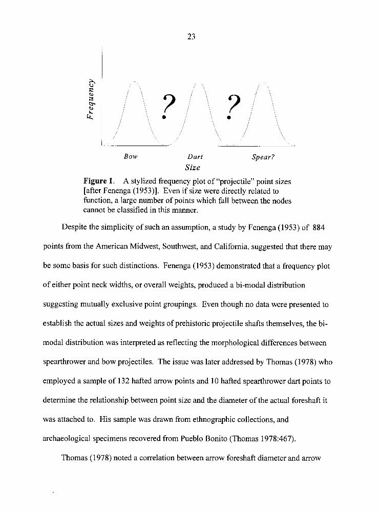
(Figure 1).
These [points] will be discussed in two categories: (1) small, thin, light, finely chipped specimens believed to have served on arrows; and (2) larger, thicker, heavier and more crudely chipped specimens we believe were used on darts thrown with atlatls. That such a distinction actually existed over vast areas of America is no longer denied by many archaeologists [Baker and Kidder 1937:5 11.
Bow Dart Spear?
Size
Figure 1. A stylized frequency plot of "projectile" point sizes [after Fenenga (1953)l. Even if size were directly related to function, a large number of points which fall between the nodes cannot be classified in this manner.
Despite the simplicity of such an assumption, a study by Fenenga (1953) of 884
points from the American Midwest, Southwest, and California, suggested that there may
be some basis for such distinctions. Fenenga (1 953) demonstrated that a frequency plot
of either point neck widths, or overall weights, produced a bi-modal distribution
suggesting mutually exclusive point groupings. Even though no data were presented to
establish the actual sizes and weights of prehistoric projectile shafts themselves, the bi-
modal distribution was interpreted as reflecting the morphological differences between
spearthrower and bow projectiles. The issue was later addressed by Thomas (1978) who
employed a sample of 132 hafted arrow points and 10 hafted spearthrower dart points to
determine the relationship between point size and the diameter of the actual foreshaft it
was attached to. His sample was drawn from ethnographic collections, and
archaeological specimens recovered from Pueblo Bonito (Thomas 1978:467).
Thomas (1978) noted a correlation between arrow foreshaft diameter and arrow
point neck width, but was unable to document a similar relationship between
spearthrower dart foreshafts and their respective points. Despite this, the data suggested
that arrow foreshafts were significantly smaller than spearthrower dart foreshafts, and
arrowheads themselves were significantly smaller than dart tips. Furthermore, a
discriminant analysis based on considerations of length, width, thickness, and neck width
of the points, correctly classified approximately 86% of the study sample (Thomas
Thomas's approach provided no mechanism for dealing with unnotched projectile
points. Shott's (1 997) reassessment of Thomas's data utilizes a significantly enlarged
sample of hafted dart points, and considers shoulder width as an alternative to neck width,
since he found the latter variable to be inadequate:
A neck width threshold of 9 mm correctly classifies 38 of 39 dart points, but misclassifies as darts 82 of 132 arrow points (62.1 percent). A threshold value of 8.5 mm produces identical results for darts but misclassifies 89 arrow points (67.4 percent). Even a threshold of 10.4 mm. One standard deviation lower than Chatters et al.'s (1995:757) mean for inferred dart points, misclassifies 57 arrows (43.2 percent) [Shott 1997:98].
In the end, however, Shott's (1997) ability to distinguish dart and arrow points is
essentially equivalent to that of Thomas's (1 978).
Published metric data and scale photographs are readily available for hundreds of
dart foreshafts recovered from dry cave sites throughout the American Great Basin and
Southwest (e.g., Berry 1976; Cosgrove 1947; Dalley 1976; Dalley and Petersen 1970;
Fenenga and Heizer 194 1 ; Guernsey 193 1 ; Guernsey and Kidder 192 1 ; Harrington 193 3;
Hattori 1982; Heizer 1938; Janetski 1980; Jennings 1957; Kidder and Guernsey 1919;
25
Loud and Harrington 1929; Pendleton 1985; Salls 1986; Smith 1963; Smith et al. 1963;
Taylor 1966; Tuohy 1982; Woodward 1937). This literature indicates that while most
dart foreshafts are approximately 0.8 cm to 1.1 cm in diameter, many are less than 0.6 cm
in diameter. In comparison, the mean diameter of arrow foreshafts from Thomas's
ethnographic sample (n = 1 18) is 0.7 cm, while the mean diameter of arrow foreshafts
from his archaeological sample (n = 14) is 0.9 cm (Thomas 1978:Tables 1 and 2). In
198 1, a 0.6 cm diameter dart foreshaft with a hafted stone point, along with five other
dart foreshafts ranging from 0.4 cm to 0.6 cm, was recovered from NC Cave, Lincoln
County, Nevada (Tuohy 1982). In reference to Thomas's (1978) study, these finds, as
well as 56 other dart foreshafts from cave sites in the vicinity of Lake Winnemucca,
Nevada, prompted Tuohy (1 982:97) to comment:
. . . I am not convinced that enough data have been marshalled [sic] to segregate arrow foreshafts from dart foreshafts on the basis of size or variability in dimensions such as length, width, weight, or shaft diameters, and the new data from "NC" Cave and the Winnemucca Lake foreshafts from a cache support this contention.
Studies such as Thomas's (1978) rely on certain normative assumptions. First, they
assume that their study samples are representative of the technology throughout time; that
shaft diameters associated with a projectile technology will remain essentially invariant
over time. Secondly, they assume that their study samples are representative of the
technology in question. In differentiating points based on metric attributes, particularly
attributes of size, studies such as these tend to overlook the effects of repair and
resharpening. Since the ethnographic and archaeological samples are comprised of
curated and cached weapons, one should instead assume that they are not in pristine,
26
unused condition (cf., Binford 1979). It is therefore reasonable to expect that such
samples may not reflect a technological ideal. Compounding the problem, is the fact that
not all bows and arrows are, or were, created equal. The type and size of the bow, the
construction of the arrow; the materials used in the shaft, whether or not it was fletched,
and whether it was intended for large game, small game, or warfare, may all generate
variability in point size and morphology.
In choosing to study examples of hafted arrow points, Thomas's sample was
unavoidably recent by way of preservation bias. This was an inevitable consequence of
the research parameters, and it biased the sample by assuming a priori that small, late
period and ethnographic arrow points and shafts are representative of bow technology
throughout time. The absence of point types known to be associated with arrows does not
constitute evidence for the absence of the bow. One must keep in mind that many early
lithic points are of a size and weight suitable for use with the bow. In fact, Browne
(1940:211) noted that even Folsom points make highly efficient arrow points. This said, I
do not mean to imply that Paleoindians may have employed a bow and arrow technology,
only that current means of projectile classification are unsatisfactory.
Projectile Identification
A further problem concerning the reconstruction of prehistoric weapons
technologies is the actual identification of projectiles per se. Ahler (1 97 1) found
evidence suggesting that bifacial "projectile" points were not always used primarily as
projectile armatures, but that they were often used as knives and multi-purpose tools.
Certain questions arise then: (1) what exactly constitutes a projectile, and (2) how do we
know that an artifact that we might otherwise label as an arrowhead or dart-point was
ever actually used as a projectile?
So-called "diagnostic impact-fractures" are touted by many analysts (e.g., Ahler and
McMillan 1975; Barton and Bergman 1982; Bergman and Newcomer 1983; Fischer,
Hansen, and Rasmussen 1984; Frison 1978; Frison, Wilson, and Wilson 1976; Holdaway
1989; Ode11 1977, 1988; Roper 1979; Shea 1988; Witthoff 1968; Woods 1988) to be
indicative of projectile impacts. For example, Bergman and Newcomer (1 983) describe
three types of "impact fracture" identified during their projectile experiments:
1. The burin-likefracture. Here one or more slivers of flint resembling burin spalls are detached from the lateral edge and the resulting broken arrowhead may be indistinguishable from an intentionally made burin.
2. Theflute-like fracture. Here a chip is removed from dorsal or ventral surface, leaving a shallow flake scar that may resemble a flat-faced burin facet or a poor attempt at fluting the arrowhead's tip.
3. The bending-fracture. This type of break occurs transversely some way down the arrowhead's length and as it is not percussion-induced there is no positive or negative bulb on either piece. In some cases, the bending break may result in further breaks on the corners of the snapped blade sections, presumably caused by one section pressing off burin-like spalls on the other [Bergman and Newcomer l983:24 1-2431.
Bergman and Newcomer (1983) employ these criteria to suggest that certain Upper
Paleolithic points may constitute projectile armatures. Similar criteria have also been cited
to support the hypothesis that Mousterian points represent hafted projectiles rather than
simple scrapers or knives, and that Neanderthals were, therefore, capable of complex
behaviour (cf., Holdaway 1989, 1990; Shea 1988, 1990; Solecki 1992).
2 8
Most archaeologists have restricted such analyses to formal points. Odell (1988),
however, has labeled large numbers of modified and unmodifiedflakes from a site in the
Lower Illinois Valley as projectile armatures. Relying primarily on the identification of
diagnostic impact-fractures, he suggests: (1) that diagnostic projectile impact fractures may
often be observed on simple retouched flakes as well as unretouched waste flakes and
detritus, (2) that the practice of employing suitable waste flakes as functional projectile
points may be widespread, and (3) that this phenomenon will have repercussions on studies
of technology and foraging efficiency. Odell's (1988) waste flake analysis is based on
previous comparative studies of impact-related breakage patterns, notably Odell and Cowan
(1 986), which used an extensive series of shooting experiments employing replicated bifacial
points and unmodified flakes as armatures on both spears and arrows.
Odell and Cowan (1986:204) describe impact-related breakage patterns as a series
of tip and base fractures classified into general types based on fracture termination as
defined by the Ho Ho Committee (1 976 Vancouver Use-wear Conference [Hayden
19791). These fracture types are dominated by snap, hinge, and step terminations in
varying combinations. Other types of macroscopic damage include burination of the
lateral edges, and a type of fracture consisting of "... shallow scars that often carry a
distance of five or more millimeters from the end and terminate in either a step or hinge"
(Odell and Cowan 1986:204). The latter type of fracture occasionally resembles
intentionally manufactured fluting and is referred to as a "shallow stephinge fracture"
(Odell and Cowan 1986:204). Various other types of use-wear such as edge-rounding,
surface polish, and linear striations were also used to identify projectile impact-related
29
damage.
Unfortunately, Odell's tabulated data (Tables 1 and 2; Odell 1988:344-345) are
confusing and it is unclear exactly what percentage of his study sample is represented by
morphological versus non-morphological (in this case waste flakes and detritus)
functional projectile points. He does state that only 3% of the functional projectile points
from the Smiling Dan site sample are found among ". . . modified type collection objects"
(presumably, morphological projectile points) (Odell 1988:346).
There is little reason to doubt that prehistoric peoples made greater use of materials
usually classified as debitage and detritus than has been popularly recognized. Yet I feel
that there are several problems inherent in the study of impact breakage patterns,
including the use of some forms of polish and striations, especially if these breakage
patterns are to be used as definitive proof of use as a projectile. These problems arise due
to both the general morphology and functional nature of points; specifically:
1) lithic projectiles generally exhibit little use-wear or haft related polish;
2) impact fractures are generally location- and orientation-specific forms of damage
that can be caused as much through thrusting, or even dropping, as from projectile-
related impact;
3) certain impact fractures on the presumed service tips of unmodified flakes often
involve a single, point loading event and cannot always be reliably distinguished
from incidental manufacturing impacts or other damage by means of traditional
analyses.
It is possible to produce flakes and blades during simple core reduction which
unintentionally exhibit sympathetic or repercussive fractures that often appear similar to
projectile point impact fractures. For example, the thin distal and lateral margins of
flakes and blades can be damaged when they strike the ground after removal from a core
or are otherwise discarded or tossed into a pile for subsequent use by the flint-knapper
Such damage would constitute an impact fracture in the true sense of the term, but not an
impact fracture caused by use as a projectile armature. Given a site with a relatively large
population of waste flakes, blades, and other debitage, a large number of pieces can be
expected to exhibit so-called impact fractures.
An investigation of flint chipping debris designed to explore the incidence of
"impact fractures" on flint debitage (Hutchings 1991 :Appendix F), demonstrated that
72.4% of a sample of 246 pieces of flint chipping debris were suitable for hafting as
practical or useable arrowheads. Of these, 15 haftable pieces (6.1 % of the original
sample) were found to exhibit damage suggestive by location, distribution and
morphology, of projectile use according to the macroscopic criteria of Odell and Cowan
(1986) as well as those of Odell (1988) and others (e.g., Ahler 1971; Barton and Bergman
1982; Bergman and Newcomer 1983; Fischer, Hansen, and Rasmussen 1984; and Roper
1979). In fact, three of the haftable pieces which exhibited so-called "diagnostic impact
fractures" also exhibited simple side-notches; one of these three exhibited simple,
uniform, bilateral side-notches.
The results obtained by this simple study demonstrate a high probability of observing projectile impact-like breakage patterns among discarded waste flakes and other debitage and detritus. Over 6% of the sample produced erroneous "use-wear". The overall morphology of these pieces, and the current definition of what constitutes a projectile point, suggests not only that they came in contact
with some target material, but that they were shot or thrown at the target material as projectile points [Hutchings 1991 :Appendix F, emphasis in original].
These results illustrate the problems inherent in employing impact breakage patterns as
proof of projectile function. While projectiles do indeed frequently exhibit these
breakage patterns, one cannot simply reverse the relationship between projectiles and
breakage patterns so that the occurrence of these patterns indicates use as a projectile.
The essential problem then is the fact that various types of fractures which may
otherwise appear identical, may result from a wide range of different events and forces, or
loading rates. For example, lithic implements may exhibit seemingly identical fractures
that were caused during manufacture, careless handling, or various instances of use. So-
called "diagnostic impact-fractures" are little more than a series of tip fractures found on
both projectile points and other pointed lithic implements and debitage. The distal tips
are the most fragile component of these implements, and it is not unreasonable to expect
frequent damage directed parallel to the long axis. The damage sustained by the tips of
projectile armatures, however, should result from much higher loading rates and exhibit
higher fracture velocities than other artifacts exhibiting morphologically similar damage,
but caused by non-projectile-related use. The problem lies in the identification of the
actual loading rate associated with a given tip fracture, or any other fracture thought to be
associated with use. If such data can be supplied by the tool, or more specifically the
fracture, in question, any and all subjective interpretive problems could be eliminated.
CHAPTER IV
THE QUANTIFICATION OF LITHIC FRACTURE VELOCITY
"Every action creates an equal and opposite reaction." - Popular paraphrase of Newton's 3rd Law of Motion -
Archaeologists have long noted the presence of various ripple-marks on the fracture
surfaces of certain isotropic, cryptocrystalline materials. In fact, the "eolith debate" at the
beginning of the twentieth century (e.g., Moir 191 1, 19 12, 191 6, 1928; Warren 1905,
191 3, 1914, 1923) focused on whether the presence of certain lithic fracture surface
features constituted proof of human manufacture. Today, fracture surface features are
commonly used to orient incomplete blades and flake fragments, and have been
successfully employed as an aid in identifying the presence of soft-hammer versus hard-
hammer reduction strategies (e.g., Hayden and Hutchings 1989).
The specific processes responsible for the formation of fracture surface features are
poorly understood among most archaeologists. This chapter presents the basic concepts
necessary to understanding the origin and nature of the fracture surface features pertinent
to this research. In order to avoid a digressive and lengthy reiteration, readers desiring
more than is offered in this brief chapter will find an excellent review and evaluation of
brittle fracture theory and wave mechanics in Tomenchuk (1985).
Fracture surface features are macro- and microscopic markings found on the ventral
surfaces of flakes and blades, and on the flake scars of cores. These are generally formed
33
as a result of momentary changes in modes of fracture, and interactions in stress fields,
along a progressing crack front.
During the production of lithic implements, the flintknapper's primary concern is
the controlled removal of flakes or blades from the core. This is achieved primarily
through manipulation of the energy imparted to the core by the knapper. With respect to
percussion flaking, for example, energy is controlled primarily by three methods: (1) by
the selective use of percussors of different densities, (2) by the angle and speed of the
impact between the percussor and core, and (3) by the selective use of percussors of
different sizes. In general fracture mechanics terms, these methods are means of varying
the loading rate.
The energy imparted to a core is transmitted in the form of a wave induced stress
field. If this energy is sufficient to rupture atomic bonds, a fracture results. Of particular
importance in the formation of certain fracture surface features, is the dynamic interaction
of the crack front with two elastic waves, the longitudinal (or dilational) wave, and the
transverse (or distortional) wave. These waves are generated by the initial loading event
and by bond rupture episodes along the progressing crack front (Tomenchuk 1985:437-
438).
Fracture Surface Features and the Determination of Fracture Velocity
Undulations are the most commonly known type of macroscopic ripple mark.
While they are not velocity dependent fracture features, they are useful indicators of the
orientation of the crack front and are, therefore, important to the discussion that follows.
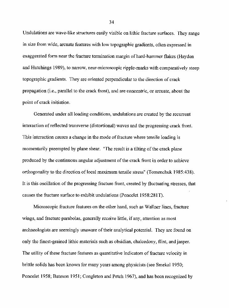
3 4
Undulations are wave-like structures easily visible on lithic fracture surfaces. They range
in size from wide, arcuate features with low topographic gradients, often expressed in
exaggerated form near the fracture termination margin of hard-hammer flakes (Hayden
and Hutchings 1989), to narrow, near-microscopic ripple-marks with comparatively steep
topographic gradients. They are oriented perpendicular to the direction of crack
propagation (i.e., parallel to the crack front), and are concentric, or arcuate, about the
point of crack initiation.
Generated under all loading conditions, undulations are created by the recurrent
interaction of reflected transverse (distortional) waves and the progressing crack front.
This interaction causes a change in the mode of fracture where tensile loading is
momentarily preempted by plane shear. "The result is a tilting of the crack plane
produced by the continuous angular adjustment of the crack front in order to achieve
orthogonality to the direction of local maximum tensile stress" (Tomenchuk 1985:438).
It is this oscillation of the progressing fracture front, created by fluctuating stresses, that
causes the fracture surface to exhibit undulations (Poncelet 1958:28 IT).
Microscopic fracture features on the other hand, such as Wallner lines, fracture
wings, and fracture parabolas, generally receive little, if any, attention as most
archaeologists are seemingly unaware of their analytical potential. They are found on
only the finest-grained lithic materials such as obsidian, chalcedony, flint, and jasper.
The utility of these fracture features as quantitative indicators of fracture velocity in
brittle solids has been known for many years among physicists (see Smekal 1950;
Poncelet 195 8; Bateson 195 1 ; Congleton and Petch 1967), and has been recognized by
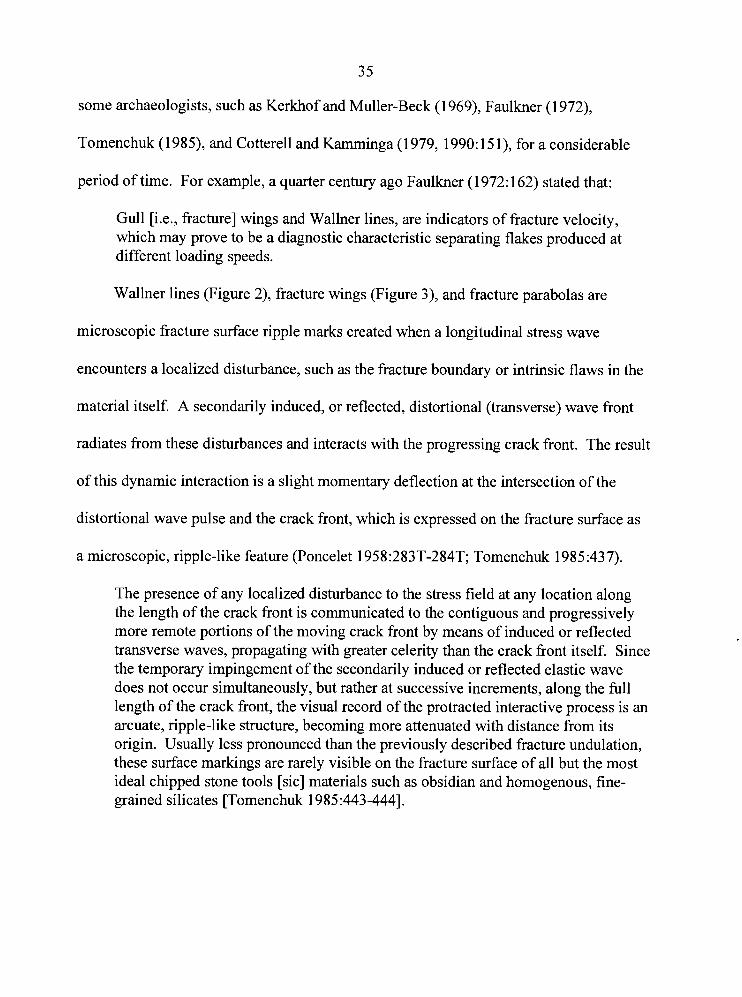
some archaeologists, such as Kerkhof and Muller-Beck (1 969), Faulkner (1 972),
Tomenchuk (1 985), and Cotterell and Kamminga (1 979, 1990: 15 I), for a considerable
period of time. For example, a quarter century ago Faulkner (1 972: 162) stated that:
Gull [i.e., fracture] wings and Wallner lines, are indicators of fracture velocity, which may prove to be a diagnostic characteristic separating flakes produced at different loading speeds.
Wallner lines (Figure 2), fracture wings (Figure 3), and fracture parabolas are
microscopic fracture surface ripple marks created when a longitudinal stress wave
encounters a localized disturbance, such as the fracture boundary or intrinsic flaws in the
material itself. A secondarily induced, or reflected, distortional (transverse) wave front
radiates from these disturbances and interacts with the progressing crack front. The result
of this dynamic interaction is a slight momentary deflection at the intersection of the
distortional wave pulse and the crack front, which is expressed on the fracture surface as
a microscopic, ripple-like feature (Poncelet 1958:283T-284T; Tomenchuk 1985:437).
The presence of any localized disturbance to the stress field at any location along the length of the crack front is communicated to the contiguous and progressively more remote portions of the moving crack front by means of induced or reflected transverse waves, propagating with greater celerity than the crack front itself. Since the temporary impingement of the secondarily induced or reflected elastic wave does not occur simultaneously, but rather at successive increments, along the full length of the crack front, the visual record of the protracted interactive process is an arcuate, ripple-like structure, becoming more attenuated with distance from its origin. Usually less pronounced than the previously described fracture undulation, these surface markings are rarely visible on the fracture surface of all but the most ideal chipped stone tools [sic] materials such as obsidian and homogenous, fine- grained silicates [Tomenchuk 1985 :443-4441.
Figure 2. Photograph of an obsidian fracture surface illustrating intersecting Wallner lines and several fine undulations. 40x magnification.
Figure 3. Photograph of an obsidian fracture surface illustrating a large fracture wing on a relatively straight fracture front. Note numerous smaller fracture wings. 40x magnification.
Wallner lines appear as ripple-like formations, attenuated along their length, which
occur at an oblique angle to the crack front. They occur when:
Sequential crack branching episodes and intrinsic or extrinsic flaws distributed at the perimeter of the plane of the fracture mirror . . . generate a series of crack front disturbances . . . . These structures intercept similar features emanating from the opposite mirror boundary and ultimately, the opposite mirror boundary itself [Tomenchuk 1985:444, emphasis in original].
Where the orientation of the fracture front is known, the maximum instantaneous fracture velocity at the site of a Wallner line may be determined from the effective angle of divergence of this fracture surface feature. Appropriate equations are available (Kerkhof 1975: 1 19) for three different configurations of Wallner lines which may be generated.
Fracture velocity (6 ) is expressed as a fraction of the transverse wave velocity
(C,). The transverse wave velocity is material dependent, and is represented by a
numerical constant. It is this property that accounts for differences in the elastic
properties of various stone tool materials.
Fracture Velocity Data Collection
Velocity dependent fracture surface features can be measured under lo1
magnification, seldom in excess of 4Ox to 60x. A Wild M3 binocular microscope with
magnifications of 6.3x, 15x, and 40x, was employed during this research. Both a 35 rnm
photographic attachment, and a tracing attachment (discussed below) were used for
recording purposes. A custom-manufactured ball-and-socket stage which allows a high
degree of tilt, and 360 degree rotation, was used to mount specimens for viewing.
Two sets of measurements are required in order to assess fracture velocity. The first
is simply a measure of the feature's distance along the length of the fracture, and is
expressed as a percentage of the terminal crack length. A high degree of precision is not
3 8
necessary, and in most cases a simple millimeter ruler laid upon the fracture surface and
observed under magnification is sufficient. Very small fracture surfaces may require the
use of a stage micrometer. In either instance, the distance from the point of fracture
initiation to the fracture feature, is divided by the overall length of the fracture surface.
The use of this measure is discussed later.
A measure of the effective angle of divergence of the longitudinal and transverse
waves constitutes the second set of measurements. Angles are measured at pertinent
locations either directly, using a protractor reticule, or indirectly, by copying the fracture
feature photographically, or by means of a microscope tracing attachment. The
microscope tracing arm manufactured by WILD for their M3 and M8 binocular
microscopes, was the method used for data collection throughout this research. This
method is far more economical than recording each and every micro-feature
photographically, and provides a relatively quick and easy means of creating an accurate,
enlarged illustration, and permanent record. Angular measures may be obtained from the
enlarged illustrations using a standard draftsman's protractor.
Naturally, the fracture surface must be oriented as close to perpendicular with the
viewing axis as possible, since the apparent angle of divergent features is affected by their
plane of orientation. Maintaining a perpendicular orientation is not always easy since the
ability to discern micro-features on highly reflective materials such as obsidian, depends a
great deal on the angle of the incident light. Once a pertinent fracture feature is located,
one must be careful to adjust the angle of the fracture surface, maintaining a relative
lighting angle so that the feature remains visible, in order to make an accurate angular
39
assessment.
Highly reflective surfaces such as obsidian, chalcedonies, and some flints, are often
difficult to light adequately without creating excessive glare. Two 9.5 watt, diffused,
flourescent lights manufactured by Bausch and Lomb (catalogue number 3 1-33-66)
proved effective in eliminating most such lighting problems.
The clarity of various fracture features observed under magnification varies
enormously, and because of this, they are not always easy to record and measure
accurately. During this research, in order to reduce measurement error, each fracture
feature was traced at least three times, sometimes as often as six or seven times. This
produced multiple assessments of each fracture feature, and provided a check for
accuracy. Multiple angular assessments were found to vary by approximately 1.5
degrees.
An informal test of the tracing arm recording and data collection method was
conducted by comparing data collected using the tracing arm, to that obtained by
photographic means. A number of different, well-defined fracture features were traced,
and each recorded on 35 mm transparency film. By projecting the 35 mm transparencies,
the recorded image is enlarged several hundred times and is easily, and accurately
measured. Average angular measures recorded for each fracture feature using these two
methods were consistently within one degree of each other.
40
Fracture Feature Configurations
The effective angle of divergence of the longitudinal and transverse waves is
expressed in various configurations of ripple marks, each requiring specific angular
measurements to be made. The first case (Figure 4a) involves a single Wallner line
originating at a point S on the fracture (mirror) boundary. Two angular measurements are
taken at any suitable point P where the orientation of the crack front can be determined,
as, for example, at the intersection of the Wallner line and an undulation.
The ratio of the fracture velocity to the distortional wave velocity is equal to the ratio of (1) the cosine of the angular displacement, a, between the normal to the crack front and the Wallner line to (2) the cosine of the angular distance, P, between the projected direction of the transverse wave propagation (from point S through point P) and the Wallner line [~omenchuk 1985:447].
In mathematical notation this value is expressed as (Kerkhof 1975:Figure 14a):
CIC, = c o s a l c o s ~ (1)
The second case (Figure 4b) involves a pair of Wallner lines, one a reflection of the
other (see Field 1971 :9, Figure 4c), converging on a single point at the lateral fracture
boundary.
The ratio of the fracture velocity to the distortional wave velocity is simply the sine of half the angular displacement, 24, between the two Wallner lines measured at [the convergence] point S, on the boundary [Tomenchuk 1985:447].
In mathematical notation this value is expressed as (Cotterell and Kamminga 1979: 109):
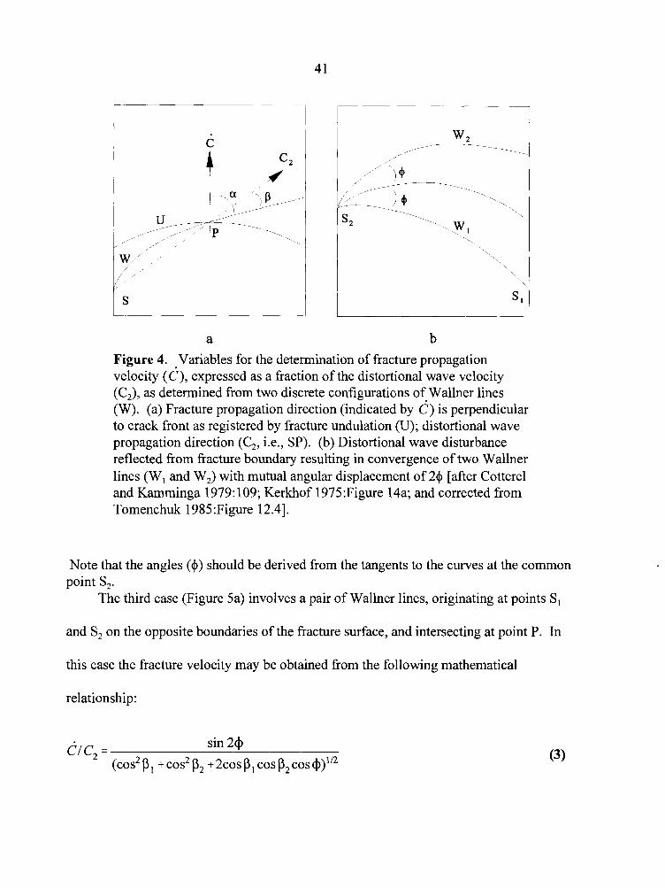
Figure 4. Variables for the determination of fracture propagation velocity (d ) , expressed as a fraction of the distortional wave velocity (C,), as determined from two discrete configurations of Wallner lines (W). (a) Fracture propagation direction (indicated by d ) is perpendicular to crack front as registered by fracture undulation (U); distortional wave propagation direction (C,, i.e., SP). (b) Distortional wave disturbance reflected from fracture boundary resulting in convergence of two Wallner lines (W, and W,) with mutual angular displacement of 24 [after Cotterel and Karnminga 1979: 109; Kerkhof 1975:Figure 14a; and corrected from Tomenchuk 1985:Figure 12.41.
Note that the angles (+) should be derived from the tangents to the curves at the common point S,.
The third case (Figure 5a) involves a pair of Wallner lines, originating at points S,
and S, on the opposite boundaries of the fracture surface, and intersecting at point P. In
this case the fracture velocity may be obtained from the following mathematical
relationship:
d1c2 = sin 2 4
(c0s2 p I + c0s2 p2 + ~ C O S PI cos p2 cos +)IR
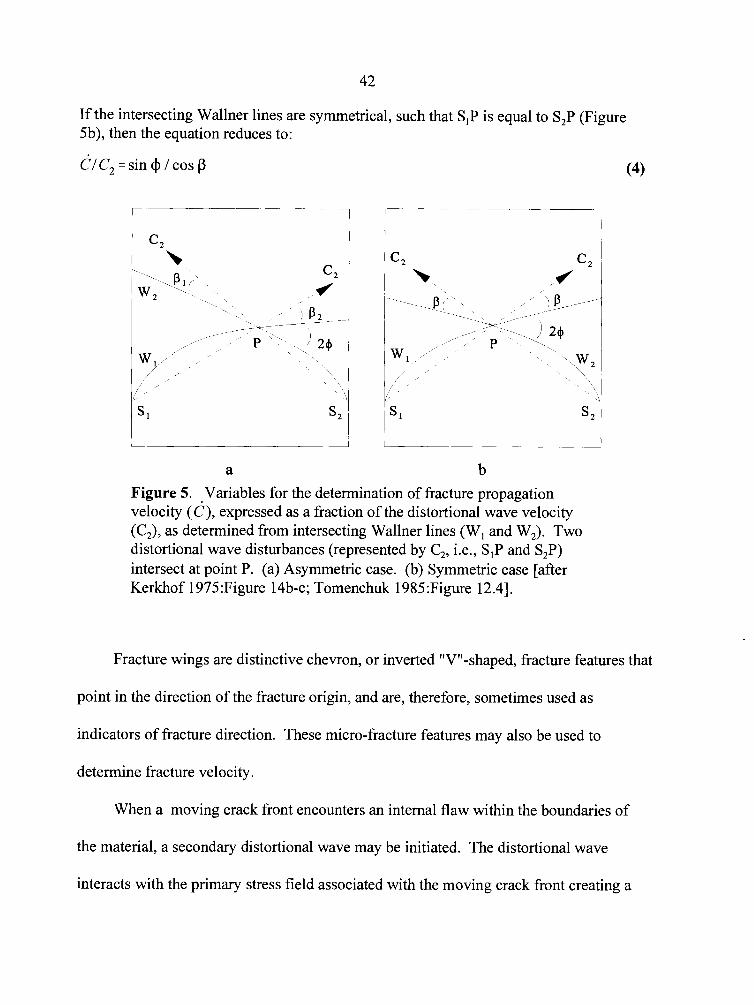
If the intersecting Wallner lines are symmetrical, such that SIP is equal to S,P (Figure 5b), then the equation reduces to:
CIC, =sin @/cos p
Figure 5. Variables for the determination of fracture propagation velocity (c), expressed as a fraction of the distortional wave velocity (C,), as determined from intersecting Wallner lines (W, and W,). Two distortional wave disturbances (represented by C,, i.e., SIP and S,P) intersect at point P. (a) Asymmetric case. (b) Symmetric case [after Kerkhof 1975:Figure 14b-c; Tomenchuk 1985:Figure 12.41.
Fracture wings are distinctive chevron, or inverted "V"-shaped, fracture features that
point in the direction of the fracture origin, and are, therefore, sometimes used as
indicators of fracture direction. These micro-fracture features may also be used to
determine fracture velocity.
When a moving crack front encounters an internal flaw within the boundaries of
the material, a secondary distortional wave may be initiated. The distortional wave
interacts with the primary stress field associated with the moving crack front creating a
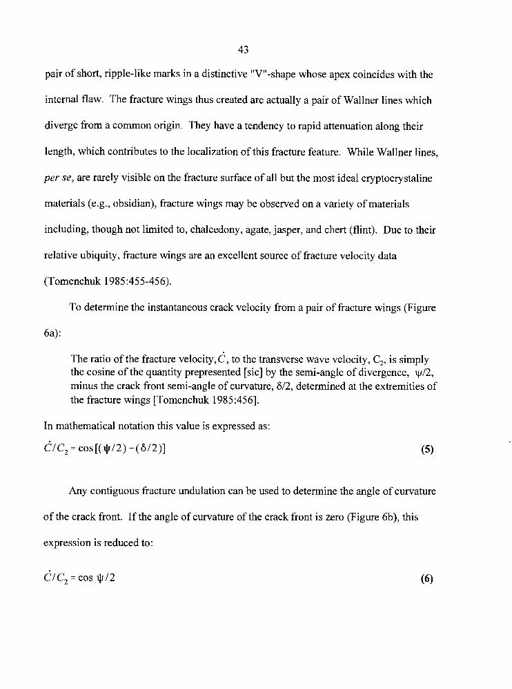
43
pair of short, ripple-like marks in a distinctive "V"-shape whose apex coincides with the
internal flaw. The fracture wings thus created are actually a pair of Wallner lines which
diverge from a common origin. They have a tendency to rapid attenuation along their
length, which contributes to the localization of this fracture feature. While Wallner lines,
per se, are rarely visible on the fracture surface of all but the most ideal cryptocrystaline
materials (e.g., obsidian), fracture wings may be observed on a variety of materials
including, though not limited to, chalcedony, agate, jasper, and chert (flint). Due to their
relative ubiquity, fracture wings are an excellent source of fracture velocity data
(Tomenchuk 1985:455-456).
To determine the instantaneous crack velocity from a pair of fracture wings (Figure
6a):
The ratio of the fracture velocity, C, to the transverse wave velocity, C2, is simply the cosine of the quantity prepresented [sic] by the semi-angle of divergence, ~ 1 2 , minus the crack front semi-angle of curvature, 612, determined at the extremities of the fracture wings [Tomenchuk 1985:456].
In mathematical notation this value is expressed as:
CIC, = cos[($12) - (8/2)]
Any contiguous fracture undulation can be used to determine the angle of curvature
of the crack front. If the angle of curvature of the crack front is zero (Figure 6b), this
expression is reduced to:
ClC, = cos 912
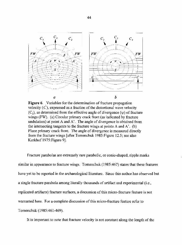
Figure 6. Variables for the determination of fracture propagation velocity (c), expressed as a fraction of the distortional wave velocity (C,), as determined from the effective angle of divergence (y ) of fracture wings (FW). (a) Circular primary crack front (as indicated by fracture undulation) at point A and A'. The angle of divergence is obtained from the intersecting tangents to the fracture wings at points A and A'. (b) Plane primary crack front. The angle of divergence is measured directly from the fracture wings [after Tomenchuk 1985:Figure 12.5; see also Kerkhof 1975:Figure 91.
Fracture parabolas are extremely rare parabolic, or conic-shaped, ripple marks
similar in appearance to fracture wings. Tomenchuk (1 985:467) states that these features
have yet to be reported in the archaeological literature. Since this author has observed but
a single fracture parabola among literally thousands of artifact and experimental (i.e.,
replicated artifacts) fracture surfaces, a discussion of this micro-fracture feature is not
warranted here. For a complete discussion of this micro-fracture feature refer to
Tomenchuk (1985:461-469).
It is important to note that fracture velocity is not constant along the length of the
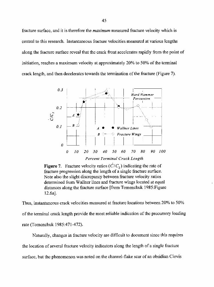
45
fracture surface, and it is therefore the maximum measured fracture velocity which is
central to this research. Instantaneous fracture velocities measured at various lengths
along the fracture surface reveal that the crack front accelerates rapidly from the point of
initiation, reaches a maximum velocity at approximately 20% to 50% of the terminal
crack length, and then decelerates towards the termination of the fracture (Figure 7).
B (-0 Fracture Wings
0
Percent Terminal Crack Length
Figure 7. Fracture velocity ratios (CJC,) indicating the rate of fracture progression along the length of a single fracture surface. Note also the slight discrepancy between fracture velocity ratios determined fiom Wallner lines and fracture wings located at equal distances along the fiacture surface [from Tomenchuk 1985:Figure 12.6al.
Thus, instantaneous crack velocities measured at fracture locations between 20% to 50%
of the terminal crack length provide the most reliable indication of the precursory loading
rate (Tomenchuk 1985:471-472).
Naturally, changes in fracture velocity are difficult to document since this requires
the location of several fracture velocity indicators along the length of a single fiacture
surface, but the phenomenon was noted on the channel-flake scar of an obsidian Clovis
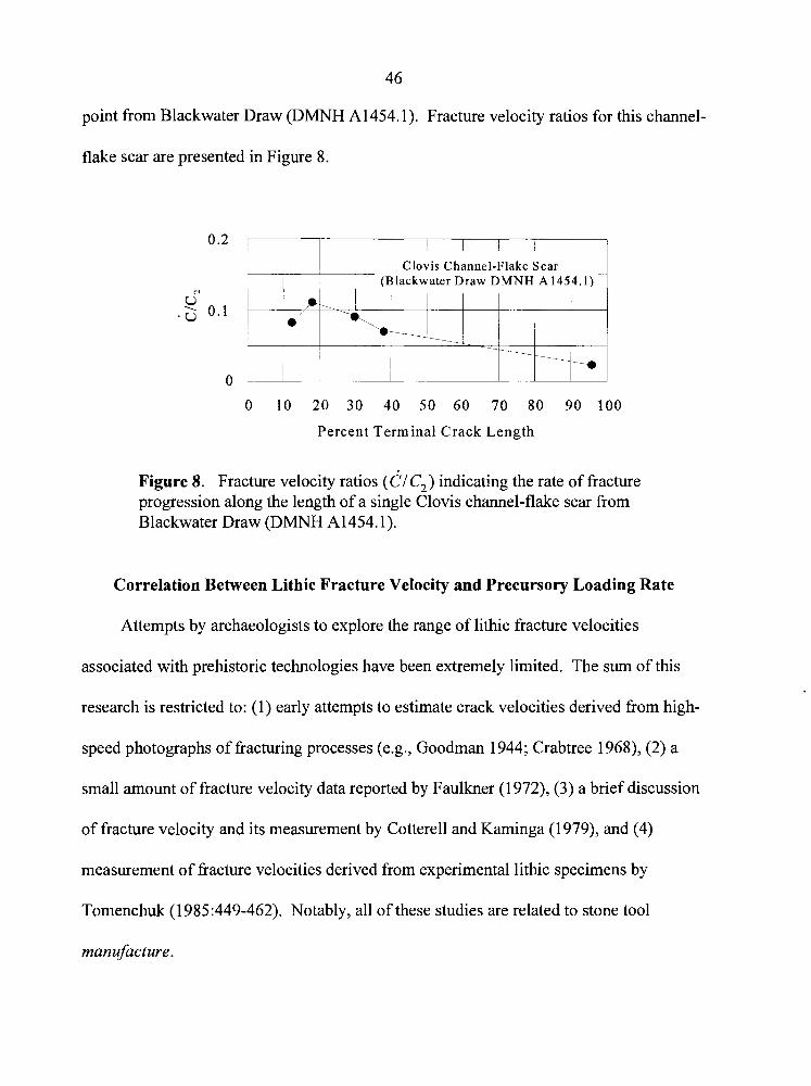
46
point from Blackwater Draw (DMNH A1454.1). Fracture velocity ratios for this channel-
flake scar are presented in Figure 8.
1 1 1 1 Clovis Channel-Flake Scar 1 (Blackwater Draw DMNH A1454.1) 1
0 10 20 30 40 50 60 70 80 90 100
Percent Terminal Crack Length
Figure 8. Fracture velocity ratios (CIC,) indicating the rate of fracture progression along the length of a single Clovis channel-flake scar from Blackwater Draw (DMNH A1454.1).
Correlation Between Lithic Fracture Velocity and Precursory Loading Rate
Attempts by archaeologists to explore the range of lithic fracture velocities
associated with prehistoric technologies have been extremely limited. The sum of this
research is restricted to: (1) early attempts to estimate crack velocities derived from high-
speed photographs of fracturing processes (e.g., Goodman 1944; Crabtree 1968), (2) a
small amount of fracture velocity data reported by Faulkner (1972), (3) a brief discussion
of fracture velocity and its measurement by Cotterell and Kaminga (1979), and (4)
measurement of fracture velocities derived from experimental lithic specimens by
Tomenchuk (1985:449-462). Notably, all of these studies are related to stone tool
manufacture.
47
Cotterell and Kaminga (1 979: 107) state that lithic fracture velocities measured
experimentally, whether the result of percussion or pressure, are in the 200 m/s to 300
m/s range. If this were true, this investigation would not be able to proceed further since
the implication is that fracture velocity determinations would be unable to distinguish
prior loading rates. Fortunately, Cotterell and Kaminga are incorrect; a fact they
themselves demonstrate during their discussion of Wallner lines observed on an obsidian
blade flake from Lipari (1 979: 109). They calculate an effective angle of divergence of 2 1
degrees for these features, producing a CI C, ratio of 0.18 (Cotterell and Kaminga
1979: 109). Given a C, value of 3425 m/s for Lipari obsidian (Tomenchuk 1985:Table
11.4), an instantaneous fracture velocity of 616.5 m/s is obtained; more than double their
stated maximum lithic fracture velocity for either pressure or percussion flaking.
Based on experimental research, Tomenchuk (1 985:472) provides a suggested
correlation between loading rate regimes and maximum instantaneous fracture velocities
for stone tool manufacture. These are listed in Table 1. He further suggests that these
loading rate regimes should remain essentially invariant for use-related fractures, but that
". . . it is not unreasonable to expect greater variability in crack velocities of the use-
related fractures which might erstwhile be regarded as sharing similar service modes"
(Tomenchuk 1 985:473).
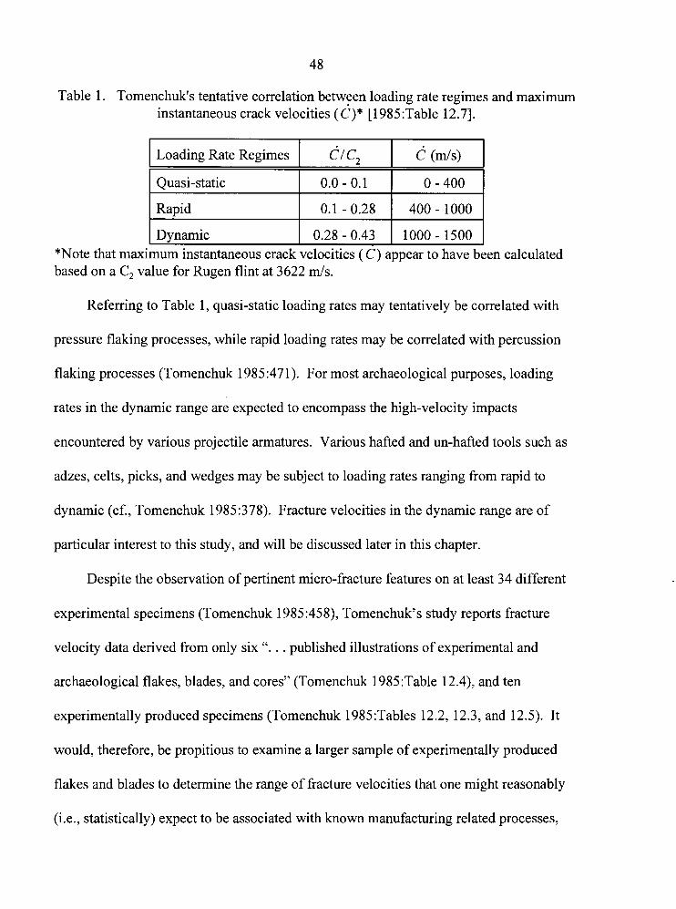
Table 1. Tomenchuk's tentative correlation between loading rate regimes and maximum instantaneous crack velocities ( c)* [I985 :Table 12.71.
Referring to Table 1, quasi-static loading rates may tentatively be correlated with
Loading Rate Regimes
pressure flaking processes, while rapid loading rates may be correlated with percussion
flaking processes (Tomenchuk l985:47 1). For most archaeological purposes, loading
*Note that maximum instantaneous crack velocities ( C) appear to have been calculated based on a C , value for Rugen flint at 3622 m/s.
dl C,
rates in the dynamic range are expected to encompass the high-velocity impacts
c (m/s)
encountered by various projectile armatures. Various hafted and un-hafted tools such as
adzes, celts, picks, and wedges may be subject to loading rates ranging from rapid to
dynamic (cf., Tomenchuk 1985:378). Fracture velocities in the dynamic range are of
particular interest to this study, and will be discussed later in this chapter.
Despite the observation of pertinent micro-fracture features on at least 34 different
experimental specimens (Tomenchuk 1985:458), Tomenchuk's study reports fracture
velocity data derived from only six ". . . published illustrations of experimental and
archaeological flakes, blades, and cores" (Tomenchuk 1985:Table 12.4), and ten
experimentally produced specimens (Tomenchuk 1985 :Tables 12.2, 12.3, and 12.5). It
would, therefore, be propitious to examine a larger sample of experimentally produced
flakes and blades to determine the range of fracture velocities that one might reasonably
(i.e., statistically) expect to be associated with known manufacturing related processes,
49
and refine the general scheme of loading rate regimes. This should later permit the
differentiation of fracture velocities that lie outside the range of manufacturing related
processes.
Quasi-static and Rapid Loading Rates
Several hundred obsidian flakes and blades collected during experimental core and
biface reduction by the author, were examined for velocity dependent fracture features.
Pressure flaking, indirect percussion, and direct percussion flaking techniques were
employed using various happing tools. These included deer antler-, and copper-tipped
pressure flaking tools; an indirect percussion punch of deer antler; an elk antler soft-
hammer percussor; and sandstone and quartzite hard-hammer percussors.
All experiments were performed using Glass Butte (Oregon) obsidian (C, = 3865
rn/s [Appendix A]). Obsidian was chosen for these experiments, not only due to its
availability, but to maximize the potential for data collection. It should be noted that the
use of any one particular raw material does not affect the validity or applicability of the
data since the measurement of divergent stress wave angles and the calculation of fracture
velocities is a non-subjective, metric operation; material-dependent elastic properties (i.e.,
transverse wave velocities [C,]) are accounted for in the fracture velocity calculations.
The experimental data are therefore considered representative of lithic reduction
processes in general.
The data reveal CIC, ratios ranging from 0.03 to 0.38 (Appendix B), and indicate
that manufacturing related fracture velocities in Glass Butte obsidian may be expected to
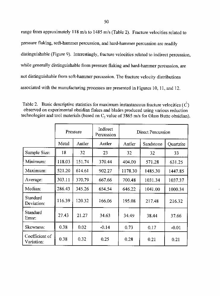
5 0
range from approximately 1 18 m/s to 1485 m/s (Table 2). Fracture velocities related to
pressure flaking, soft-hammer percussion, and hard-hammer percussion are readily
distinguishable (Figure 9). Interestingly, fracture velocities related to indirect percussion,
while generally distinguishable from pressure flaking and hard-hammer percussion, are
not distinguishable from soft-hammer percussion. The fracture velocity distributions
associated with the manufacturing processes are presented in Figures 10, 1 1, and 12.
Table 2. Basic descriptive statistics for maximum instantaneous fracture velocities ( 6 ) observed on experimental obsidian flakes and blades produced using various reduction
technologies and tool materials (based on C, value of 3865 m/s for Glass Butte obsidian).
I Sample Size:
1 Minimum:
I Maximum:
1 Average:
I Median:
Standard Deviation:
Standard
Coefficient of Variation:
Indirect Pressure
Percussion Direct Percussion
Metal Antler Antler Antler Sandstone
18 3 2 23 3 2 3 2
1 18.03 15 1.74 370.44 404.00 571.28
521.20 614.61 902.27 1178.30 1485.30
303.1 1 370.79 667.66 700.48 103 1.34
286.43 345.26 654.54 646.22 1041 .OO
Quartzite
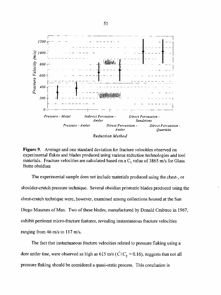
I
- - - - - - - - - - - - - - - - - - - - - - - - - - - - - - - - - - - -
O -L--4 Pressure - Metal Indirect Percusion - Dzrect Percussion -
Antler Sandstone Pressure -Antler Direct Percussion - Direct Percussion -
Antler Quartzite
Reduction Method
Figure 9. Average and one standard deviation for fracture velocities observed on experimental flakes and blades produced using various reduction technologies and tool materials. Fracture velocities are calculated based on a C, value of 3865 m/s for Glass Butte obsidian
The experimental sample does not include materials produced using the chest-, or
shoulder-crutch pressure technique. Several obsidian prismatic blades produced using the
chest-crutch technique were, however, examined among collections housed at the San
Diego Museum of Man. Two of these blades, manufactured by Donald Crabtree in 1967,
exhibit pertinent micro-fracture features, revealing instantaneous fracture velocities
ranging from 46 m/s to 11 7 m/s.
The fact that instantaneous fracture velocities related to pressure flaking using a
deer antler tine, were observed as high as 615 m/s (die, = 0.16), suggests that not all
pressure flaking should be considered a quasi-static process. This conclusion is
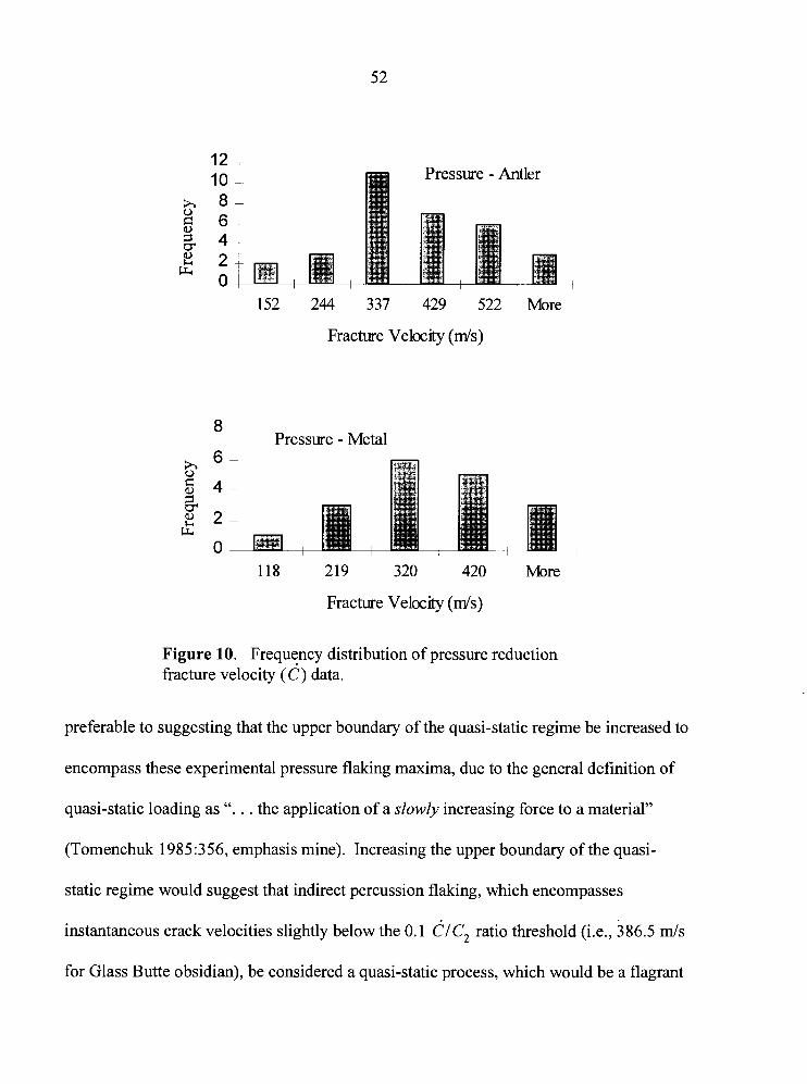
I L
10 Pressure - Antler x 8 * 6 8
4 2 2
C4 0
152 244 337 429 522 More
Fracture Velocrty ( d s )
8 T Pressure - Metal
118 219 320 420 More
Fracture Velocity ( d s )
Figure 10. Frequency distribution of pressure reduction fracture velocity (d) data.
preferable to suggesting that the upper boundary of the quasi-static regime be increased to
encompass these experimental pressure flaking maxima, due to the general definition of
quasi-static loading as ". . . the application of a slowly increasing force to a material"
(Tomenchuk 1985:356, emphasis mine). Increasing the upper boundary of the quasi-
static regime would suggest that indirect percussion flaking, which encompasses
instantaneous crack velocities slightly below the 0.1 CIC, ratio threshold (i.e., 386.5 mls
for Glass Butte obsidian), be considered a quasi-static process, which would be a flagrant
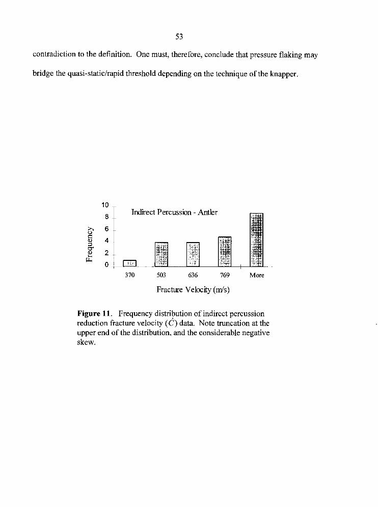
5 3
contradiction to the definition. One must, therefore, conclude that pressure flaking may
bridge the quasi-staticlrapid threshold depending on the technique of the knapper.
8 Indirect Percussion - Antler
h 6 0
8 4 1 cr 2
Cr, 0
370 503 636 769 More
Fracture Velocrty (mk)
Figure 11. Frequency distribution of indirect percussion reduction fracture velocity (c) data. Note truncation at the upper end of the distribution, and the considerable negative skew.
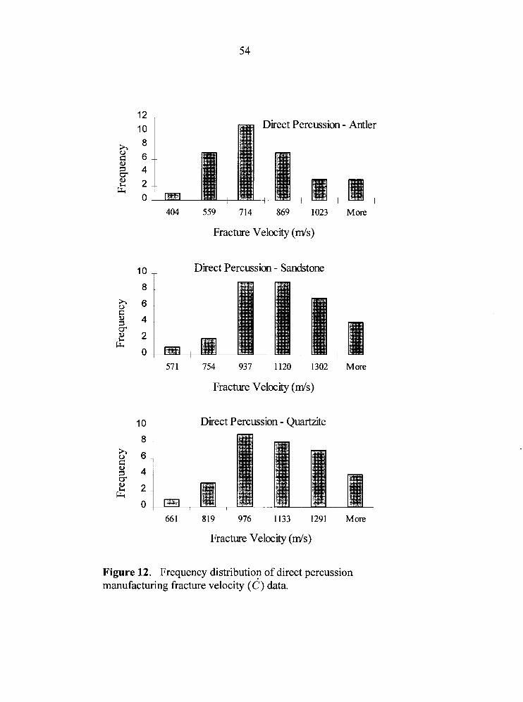
12 10 Direct Percussion - Antler 8
2 6 0
4 5 2 2
F4 0
404 559 714 869 1023
Fracture Veloclty ( d s )
lo T Direct Percussion - Sandstone
Fracture Velocity ( d s )
Direct Percussion - Quartzite
Fracture Velocity ( d s )
More
More
Figure 12. Frequency distribution of direct percussion manufacturing fracture velocity (c) data.
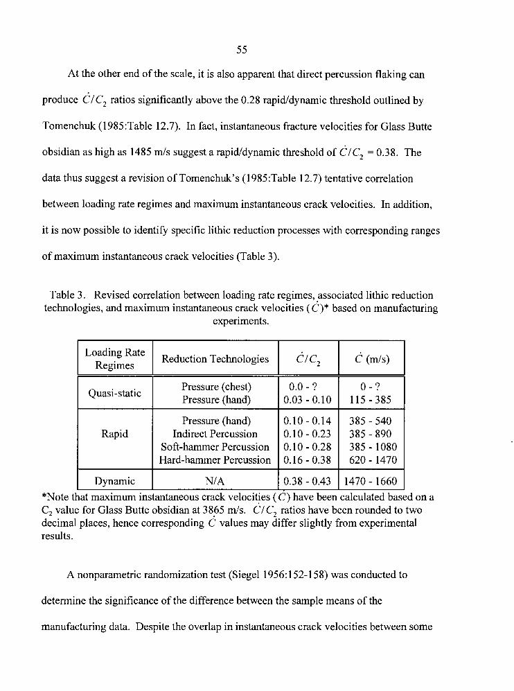
55
At the other end of the scale, it is also apparent that direct percussion flaking can
produce dlc, ratios significantly above the 0.28 rapiddynamic threshold outlined by
Tomenchuk (1985:Table 12.7). In fact, instantaneous fracture velocities for Glass Butte
obsidian as high as 1485 d s suggest a rapiddynamic threshold of CIC, = 0.38. The
data thus suggest a revision of Tomenchuk's (1985:Table 12.7) tentative correlation
between loading rate regimes and maximum instantaneous crack velocities. In addition,
it is now possible to identify specific lithic reduction processes with corresponding ranges
of maximum instantaneous crack velocities (Table 3).
Table 3. Revised correlation between loading rate regimes, associated lithic reduction technologies, and maximum instantaneous crack velocities j d )* based on manufacturing
experiments.
Loading Rate Regimes
C, value for Glass Butte obsidian at 3865 d s . CIC, ratios have been rounded to two decimal places, hence corresponding c values may differ slightly from experimental results.
Quasi-static
Rapid
Dynamic
A nonparametric randomization test (Siege1 1956: 152- 158) was conducted to
determine the significance of the difference between the sample means of the
manufacturing data. Despite the overlap in instantaneous crack velocities between some
Reduction Technologies
*Note that maximum instantaneous crack velocities ( C) have been calculated based on a
Pressure (chest) Pressure (hand)
Pressure (hand) Indirect Percussion
Soft-hammer Percussion Hard-hammer Percussion
NI A
dl c, C (mls)
0.0 - ? 0.03-0.10
0.10-0.14 0.10 - 0.23 0.10 - 0.28 0.16 - 0.38
0.38-0.43
0 - ? 115-385
385-540 385 - 890 385 - 1080 620 - 1470
1470- 1660
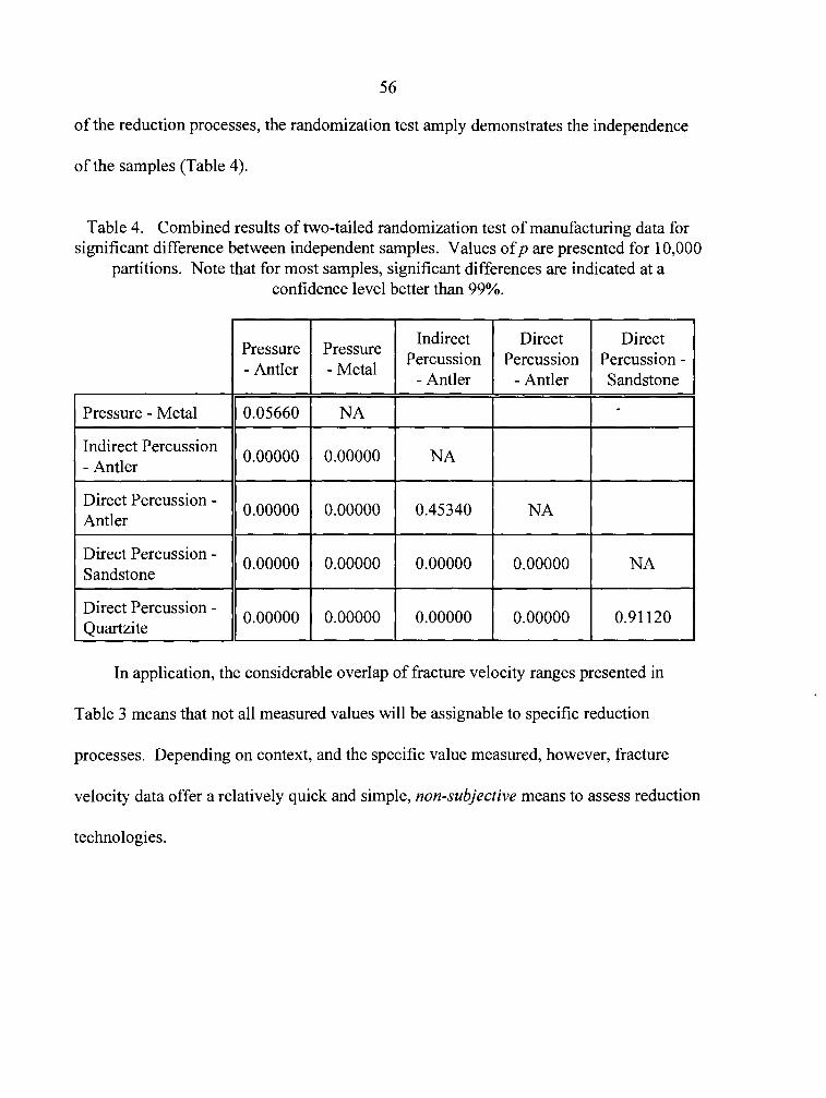
of the reduction processes, the randomization test amply demonstrates the independence
of the samples (Table 4).
Table 4. Combined results of two-tailed randomization test of manufacturing data for significant difference between independent samples. Values o fp are presented for 10,000
partitions. Note that for most samples, significant differences are indicated at a confidence level better than 99%.
In application, the considerable overlap of fracture velocity ranges presented in
Table 3 means that not all measured values will be assignable to specific reduction
processes. Depending on context, and the specific value measured, however, fracture
velocity data offer a relatively quick and simple, non-subjective means to assess reduction
technologies.
Dynamic Loading Rates
The expectation that lithic projectile armatures, subject to high-velocity impacts,
would exhibit fracture velocities in the dynamic range, was investigated during previous
-esearch (Hutchings 1991). Velocity dependent fracture surface features were observed
In damaged flint microliths (truncated rectangles) suspected, through the application of
lesign theory analysis, to have been used prehistorically as elements of composite
xojectile armatures. Average CIC, ratios ranging from 0.37 to 0.52, corresponding to
'racture velocities ranging from 1354 m/s to 1873 m/s (instantaneous maxima ranged
'rom 1268 d s to 2 129 m/s) (corrected from Hutchings 199 1 :Table 7.15) based on a C,
~alue of 3622 d s for Rugen flint, were obtained from fracture wings exhibited by these
irtifacts. These fracture velocities compared favorably with those derived from limited
.eplication experiments where flint microliths, mounted on arrow shafis as composite
irmatures, were shot into meat and bone targets. Average fracture velocities from the
.eplication experiments ranged from 1387 d s to 1498 m/s (instantaneous maxima ranged
?om 1 18 1 m/s to 18 1 1 d s ) (Hutchings 1991 :Table 7.14).
The research suggested that the upper range of dynamic fracture velocities, would
ieed to be extended beyond Tomenchuk's (1 985:Table 12.7) tentative 1500 m/s limit
corresponding to a CIC, ratio of 0.43) to include fractures resulting from use-related
unctions such as high-velocity impacts (Hutchings 199 1 :2 12). Most importantly, it
uggested that lithic fracture velocity data could be used to identify artifacts used as
~rojectile armatures (i.e., artifacts subject to high-velocity impacts), and that it may be
possible to distinguish between loading rates attributable to specific projectile
technologies in a manner similar to that demonstrated for reduction technologies.
Terminal Fracture Velocity
The terminal fracture velocity (c;) for a given material, represents the maximum
transmission rate of longitudinal waves within that material. The issue of terminal
fracture velocity is important since as wave propagation velocities approach this
boundary, it will become increasingly difficult to distinguish variation in prior loading
rates. That is to say that at some point, regardless of any further increases in loading rate,
resulting fracture velocities should reflect little more than the terminal fracture velocity of
the material.
Fracture mechanics researchers have attempted to determine the theoretical velocity
limit for a moving crack in a brittle solid. Some (Mott 1948; Poncelet 1944; 1958; 1964;
Roberts and Wells 1954) have attempted to demonstrate that the maximum fracture
velocity is 0.5 of the transverse wave velocity. Stroh (1957:454), and Broberg (1964,
cited in Tomenchuk 1985:395) equated the terminal fracture velocity with a fraction of
the Rayleigh surface wave velocity. None of these theoretical attempts to estimate
terminal fracture velocity are borne out by the empirical evidence (Schardin 1959;
Tomenchuk 1985:395-396).
... the absence of published information on the terminal crack velocity of chipped tool stone exacerbates the already difficult task of determining the loading rate dependency of crack velocities. The immediate objective, therefore, is to derive representative values of d, for a sample of chipped tool rocks [Tomenchuk 1985:380].
Tomenchuk reasons that like glass and norite, whose terminal fracture velocities
have been measured empirically, chipped-stone silicates are:
. . . hard, elastic, isotropic solids whose chemical composition is predominantly silicon dioxide. Based on the strength of the correspondence between the velocity ratios of glass and norite - especially CF /C, - I conclude that chipped-tool rocks will possess comparable values of velocity ratios.
In principle, the manifestation of specific fracture features should exhibit the same crack propagation ranges and thresholds for both glass and the cryptocrystalline solids such as cherts and flints [Tomenchuk 1985:399].
The empirically determined terminal fracture velocity for norite is 1875 m/s
(Bieniawski 1968:Table 2), while that of soda-lime glass is 1580 m/s (Field 1971 :Table
During this research, instantaneous fracture velocities as high as 223 1 m/s were
observed on experimental impact-damaged obsidian points, indicating that the terminal
fracture velocity of Glass Butte obsidian is considerably higher than that of either soda-
lime glass or norite. A simple experiment was therefore conducted to explore the
terminal fracture velocity of Glass Butte obsidian.
Lacking access to mechanical testing equipment, a less rigorous experiment was
conducted with the assistance of the Firearms Section of the R.C.M.P. Forensic
Laboratory (Vancouver). Several Glass Butte obsidian cores were subjected to extremely
high-velocity impacts by firing bullets into their prepared striking platforms. The
obsidian targets were clamped inside a bullet trapping device at a range of approximately
3 m, and impacts ranging from 308.2 m/s to 983.0 m/s were achieved using various
60
ammunition. Projectile velocities were measured using a photo-electric device similar to
that used during replication experiments described later in Chapter V.
Four types of ammunition spanning a broad range of velocities were employed.
These included standard .22 short and .22 long rifle, along with copper-jacketed 30-MI
carbine and .223 (high-velocity assault rifle) caliber. All ammunition, except for the
relatively slow .22 short, shattered the obsidian cores. The ballistic and lithic fracture
velocity data are presented in Table 5. Fracture velocity data were recovered from nine
obsidian prepared cores and produced CIC, ratios ranging from 0.535 to 0.648,
indicating fracture velocities spanning 2068 d s to 2505 m/s (x = 2324 m/s; s = 115 d s ) .
Interestingly, fracture parabolas, extremely rare on other types of fracture surfaces, were
observed on fragments from most of the nine cores.
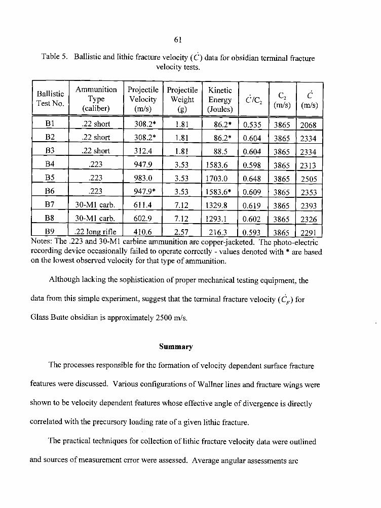
Table 5. Ballistic and lithic fracture velocity (6 ) data for obsidian terminal fracture velocity tests.
Although lacking the sophistication of proper mechanical testing equipment, the
Ballistic Test No'
B1
B2
B3
B4
B5
B6
B7
B8
B9
data from this simple experiment, suggest that the terminal fracture velocity (G) for
Glass Butte obsidian is approximately 2500 d s .
Summary
The processes responsible for the formation of velocity dependent surface fracture
features were discussed. Various configurations of Wallner lines and fracture wings were
shown to be velocity dependent features whose effective angle of divergence is directly
correlated with the precursory loading rate of a given lithic fracture.
The practical techniques for collection of lithic fracture velocity data were outlined
and sources of measurement error were assessed. Average angular assessments are
Notes: The .223 and 30-M1 carbine ammunition are copper-jacketed. The photo-electric recording device occasionally failed to operate correctly - values denoted with * are based on the lowest observed velocity for that type of ammunition.
Ammunition TY pe
(caliber)
.22 short
.22 short
.22 short
.223
.223
.223
30-M1 cab.
30-MI carb.
.22 long rifle
Projectile Velocity
( d s )
308.2*
308.2*
3 12.4
947.9
983.0
947.9*
61 1.4
602.9
4 10.6
Projectile Weight
(g)
1.81
1.81
1.81
3.53
3.53
3.53
7.12
7.12
2.57
Kinetic Energy (Joules)
86.2*
86.2"
88.5
1583.6
1703.0
1583.6*
1329.8
1293.1
216.3
C/C,
0.535
0.604
0.604
0.598
0.648
0.609
0.619
0.602
0.593
c2
( d s )
3865
3865
3865
3865
3865
3865
3865
3865
3865
c ( d s )
2068
2334
2334
2313
2505
2353
2393
2326
2291
62
expected to be accurate to within one degree. Fracture velocity assessments within the
range observed during manufacture-related reduction, based on a C, value of 3865 m/s for
Glass Butte obsidian, are therefore expected to be accurate to within approximately 34 +
1 d s .
Common techniques of lithic reduction were found, through examination of
replicated obsidian flakes and blades, to produce CIC, ratios ranging from 0.01 3 to
0.384, corresponding to fracture velocities ranging from approximately 50 m/s to 1485
m/s . Tomenchuk's (1985:Table 12.7) tentative correlations between loading rate regimes
and maximum instantaneous crack velocities were revised to incorporate these data. In
addition, specific lithic reduction processes were identified with corresponding ranges of
maximum instantaneous crack velocities. The terminal fracture velocity (6,) of Glass
Butte obsidian was determined to be approximately 2500 d s .
Experimentation, both as part of this research, and by Tomenchuk (1 98S), has
demonstrated the applicability of lithic fracture velocity determination as an effective
means of analysis of archaeological materials. Fracture velocity assessments generate
non-subjective measures of empirical data which reveal the precursory loading rate of a
given lithic fracture. Unlike most other types of archaeological data, they are not subject
to alteration by cultural or natural processes that may affect their representability; the
precursory loading rate is the result of a cultural process, but the specific morphological
expression of velocity-dependent fracture features is the result of universal physical laws.
In a sense, each velocity-dependent feature represents a moment frozen in time; a
measurable event reflecting the action that produced it.
CHAPTER V
REPLICATION AND EXPERIMENTATION
"Perhaps how it comes to be is really more distinctive . . . than what it is." - Alfred Kroeber -
The replication of prehistoric artifacts has come to be recognized as a valuable
means of technological and systemic analysis. It is, by necessity, the primary analytical
approach employed by researchers involved in any aspect of experimental archaeology,
including lithic analysis. Prior to the development of hypotheses regarding any aspect of
technology, a certain degree of familiarity with that technology, with respect to materials,
construction, and use are required. This type of familiarity is best gained through
replication, -and the actual use of the replicated artifact.
A well known exponent of lithic artifact replication, Donald Crabtree (1 975: 106),
wrote:
. . . experimental archaeology must be related to the specific aboriginal concepts of a particular technology or cluster of techniques and then used to replicate the stages of manufacture from the raw material to completion.
Defining replication, in this case with respect to stone tools, and outlining some of
the benefits of the replicative approach, Flenniken (1 98 1 :2) stated that:
Replication, in its strictest sense, is reproducing stone tools, using the aboriginal artifacts as controls, using stoneworking fabricators similar to the ones in aboriginal use, employing the same raw materials, and following what can be demonstrated to be the same reduction technology. Therefore, the end products including the debitage, sequential stages of manufacture, and rejuvenated tools should be the same or very similar to the aboriginal controls in terms of technical category percentages, morphologies, and technologies.
Despite widespread interest in the spearthrower, there is surprisingly very little
reliable data available concerning its performance. A survey of the current literature
reveals considerable disparity in assessments of spearthrower effectiveness. Unlike bow
and arrow technologies, which have been reasonably well researched over the past
:entury, archaeologists have little reliable data regarding the most important variables of
spearthrower performance; dart weights, effective range, and projectile velocity.
Several factors contribute to the current variability in our knowledge of
spearthrower performance. The most important of these may be a general lack of
familiarity and requisite skill with the device which would permit a reasonable
~sessment of the technology. In a pioneering experimental study, Browne (1940:211)
stated "any close degree of accuracy is impossible with the atlatl and the spear." His
iescription of throwing technique explains why: "The throw is a fast overhand sweep
[that] lifts the spear to a height above the head equal to the length of both the arm and the
3tlatl and this uncontrolled throw is the cause of the large angle of error" (Browne
I940:211-212). This basic error in throwing technique was repeated by both Butler
: 1975: 105) and Patterson (1 977: 159), and may account for a generalized perception of the
spearthrower as an awkward and inaccurate weapon.
Prior to developing a program of fracture velocity experiments, it was therefore
necessary to explore the nature of spearthrower dynamics. Three characteristics of
spearthrower performance had to be assessed: (I) the practical range of the weapon under
65
reasonable hunting conditions, (2) the practical range of spearthrower dart velocities
associated with various dart weights, (3) and the final velocity and kinetic energy of the
dart upon impact with a target at hunting-related, down-range distances. In addition,
since each of these characteristics are affected by the weight of the projectile, an
assessment of dart weights was necessary prior to any investigation of spearthrower
performance.
Reconstruction of the Fluted-Point-Tipped Projectile
A basic, and reasonable assumption made by Paleoindian researchers is that fluted
points were intended to be hafted, though no complete fluted point-tipped projectiles have
yet been recovered. For the experiments that follow, it is necessary to develop a
reasonable approximation of the overall weight of the hypothetical fluted point-tipped
dart. Weight is an important factor limiting the speed imparted to a projectile, and
contributing to the kinetic energy associated with impact. The size of the shaft and
foreshaft is not as important to most experiments as the weight, but may affect or limit
the performance of a projectile. It will be necessary, however, to estimate the weight
based on the overall size of the shaft elements. The limitations of this approach are duly
noted, but no other means of reconstruction are available
Reconstruction data based on Paleoindian-related research
Researchers have suggested, either explicitly or implicitly, that the Clovis projectile
consisted minimally of the Clovis point, mounted on either a wooden, bone, antler, or
ivory foreshaft with the aid of binding and mastic. This in turn was either bound to a
66
wooden mainshaft or connected via a friction-based socket mount (Dunbar 1991; Frison
1989; Lahren and Bonnichsen 1974; Stanford 1991).
Examining Clovis point widths from the Vail site, Gramly (1 984: 1 12- 1 13) states
that specimens narrower than 24-25 mm were unfinished (i.e., lack edge grinding) and
discarded, while specimens only a few millimeters wider were finished, hafted, and used.
He hypothesizes that the smaller, unfinished points were discarded if their maximum
widths were less than that of the existing haft for which they were intended, since they
would be ineffective if their edges were enclosed by the haft. He concludes that the
shafts employed at the Vail site were 24-25 mm in diameter (Gramly 1984: 1 13). He also
cites ethnographic and historic sources which indicate that thrusting spears have large
shafts, approximately 25 mm in diameter, rarely greater, while javelins and spearthrower
darts are much narrower. He suggests, therefore, that the Vail Clovis points were used as
armatures for spears, rather than spearthrower darts.
Gramly's hypothesis does not account for the fact that the Clovis knappers chose to
flute points that they supposedly knew were too small to fit the large shafts. Channel-
flake removal is usually thought of as the most difficult task in shaping a fluted-point,
while edge-grinding is undoubtedly the simplest. Assuming that these under-sized points
were initially intended for the same use as the larger specimens, it does not seem
economical or even logical to bring a point to such a near-finished state only to discard it
after all the difficult stages had been completed. Gramly's conclusion also suggests that
haft diameters were greater than the maximum width of channel flake scars exhibited by
any of the Vail points, and ". . . also exceeds in width any group of overlapping channel
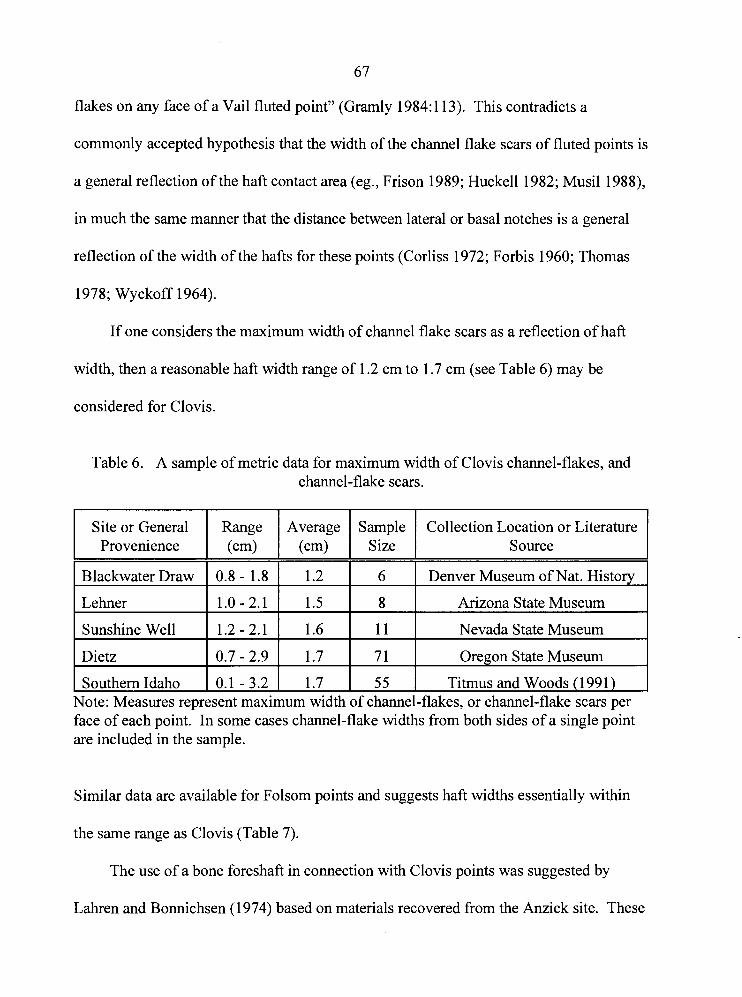
67
flakes on any face of a Vail fluted point" (Gramly 1984: 1 13). This contradicts a
commonly accepted hypothesis that the width of the channel flake scars of fluted points is
a general reflection of the haft contact area (eg., Frison 1989; Huckell 1982; Musil 1988),
in much the same manner that the distance between lateral or basal notches is a general
reflection of the width of the hafts for these points (Corliss 1972; Forbis 1960; Thomas
1978; Wyckoff 1964).
If one considers the maximum width of channel flake scars as a reflection of haft
width, then a reasonable haft width range of 1.2 cm to 1.7 cm (see Table 6) may be
considered for Clovis.
Table 6. A sample of metric data for maximum width of Clovis channel-flakes, and channel-flake scars.
Site or General Provenience
Blackwater Draw
Lehner
Sunshine Well
Dietz
Southern Idaho Vote: Measures rep1
0.1 - 3.2 1 1.7 :sent maximum width
Sample Size
6
Collection Location or Literature Source
Denver Museum of Nat. Historv
8
11
face of each point. In some cases channel-flake widths from both sides of a single point are included in the sample.
Arizona State Museum
Nevada State Museum
7 1
55
Similar data are available for Folsom points and suggests haft widths essentially within
the same range as Clovis (Table 7).
Oregon State Museum
Titmus and Woods (1 99 1)
The use of a bone foreshaft in connection with Clovis points was suggested by
Lahren and Bonnichsen (1974) based on materials recovered from the Anzick site. These
of channel-flakes, or channel-flake scars per
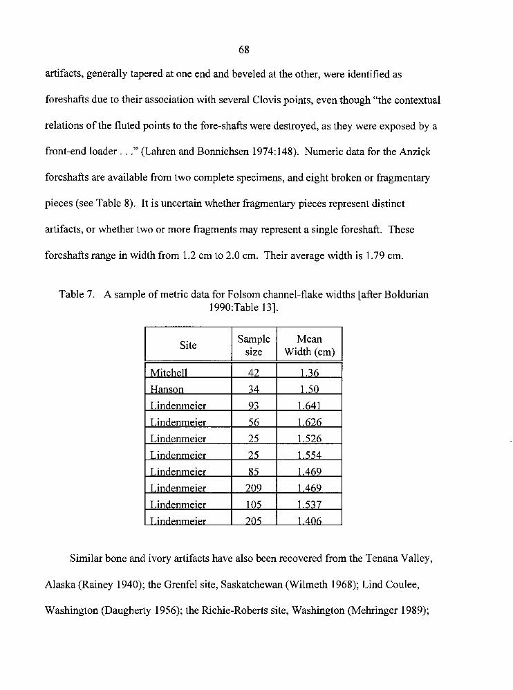
68
artifacts, generally tapered at one end and beveled at the other, were identified as
foreshafts due to their association with several Clovis points, even though "the contextual
relations of the fluted points to the fore-shafts were destroyed, as they were exposed by a
front-end loader . . ." (Lahren and Bonnichsen 1974: 148). Numeric data for the Anzick
foreshafts are available from two complete specimens, and eight broken or fragmentary
pieces (see Table 8). It is uncertain whether fragmentary pieces represent distinct
artifacts, or whether two or more fragments may represent a single foreshaft. These
foreshafts range in width from 1.2 cm to 2.0 cm. Their average width is 1.79 cm.
Table 7. A sample of metric data for Folsom channel-flake widths [after Boldurian 1990:Table 131.
Site Sample I size I Width Mern (cm) I
Similar bone and ivory artifacts have also been recovered from the Tenana Valley,
Alaska (Rainey 1940); the Grenfel site, Saskatchewan (Wilmeth 1968); Lind Coulee,
Washington (Daugherty 1956); the Richie-Roberts site, Washington (Mehringer 1989);
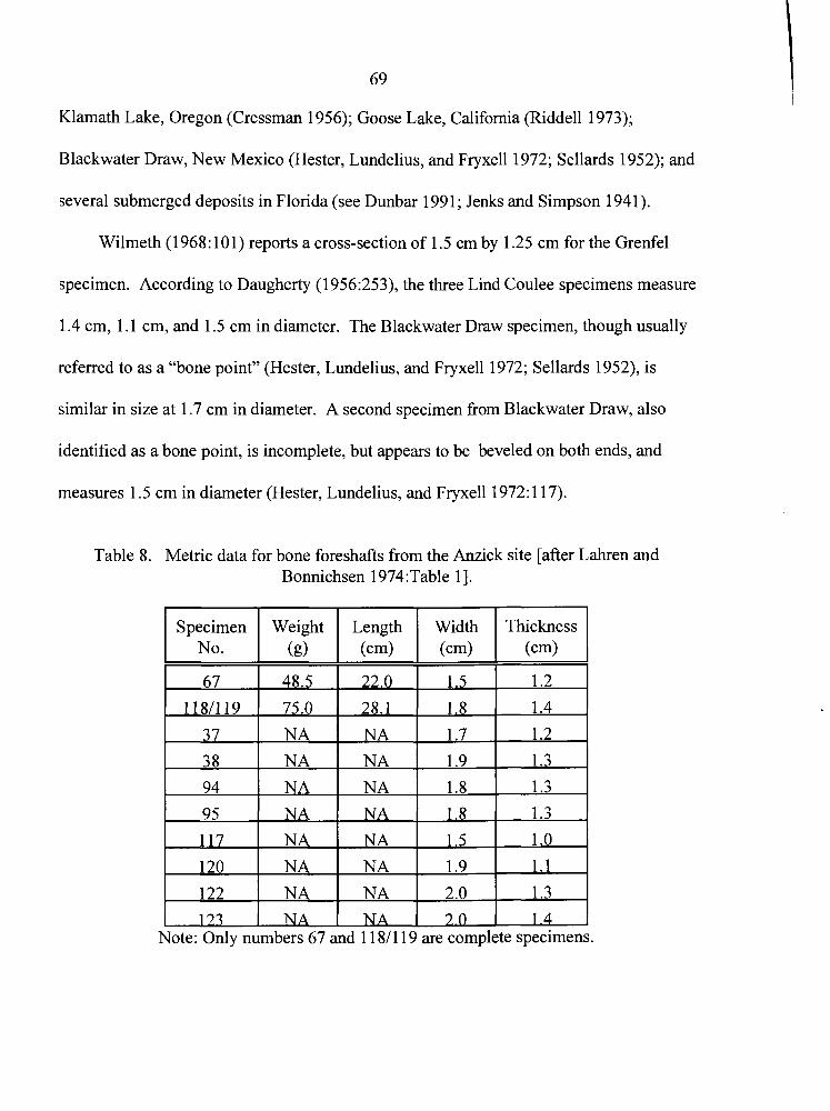
69
Klamath Lake, Oregon (Cressman 1956); Goose Lake, California (Riddell 1973);
Blackwater Draw, New Mexico (Hester, Lundelius, and Fryxell 1972; Sellards 1952); and
several submerged deposits in Florida (see Dunbar 1991 ; Jenks and Simpson 1941).
Wilmeth (1 968: 10 1) reports a cross-section of 1.5 cm by 1.25 cm for the Grenfel
specimen. According to Daugherty (1956:253), the three Lind Coulee specimens measure
1.4 cm, 1.1 cm, and 1.5 cm in diameter. The Blackwater Draw specimen, though usually
referred to as a "bone point" (Hester, Lundelius, and Fryxell 1972; Sellards 1952), is
similar in size at 1.7 cm in diameter. A second specimen from Blackwater Draw, also
identified as a bone point, is incomplete, but appears to be beveled on both ends, and
measures 1.5 cm in diameter (Hester, Lundelius, and Fryxell 1972: 1 17).
Table 8. Metric data for bone foreshafts from the Anzick site [after Lahren and Bonnichsen 1974:Table 11.
-
Specimen No.
67
122
173
-
Weight (g)
48.5
Note: Only numbers 67 and 1 1811 19 are complete specimens.
NA
NA
Thickness (cm)
1.2
Length (cm)
22.0
NA
NA
--
Width (cm)
1.5
2.0
7 0
1.3
1.4
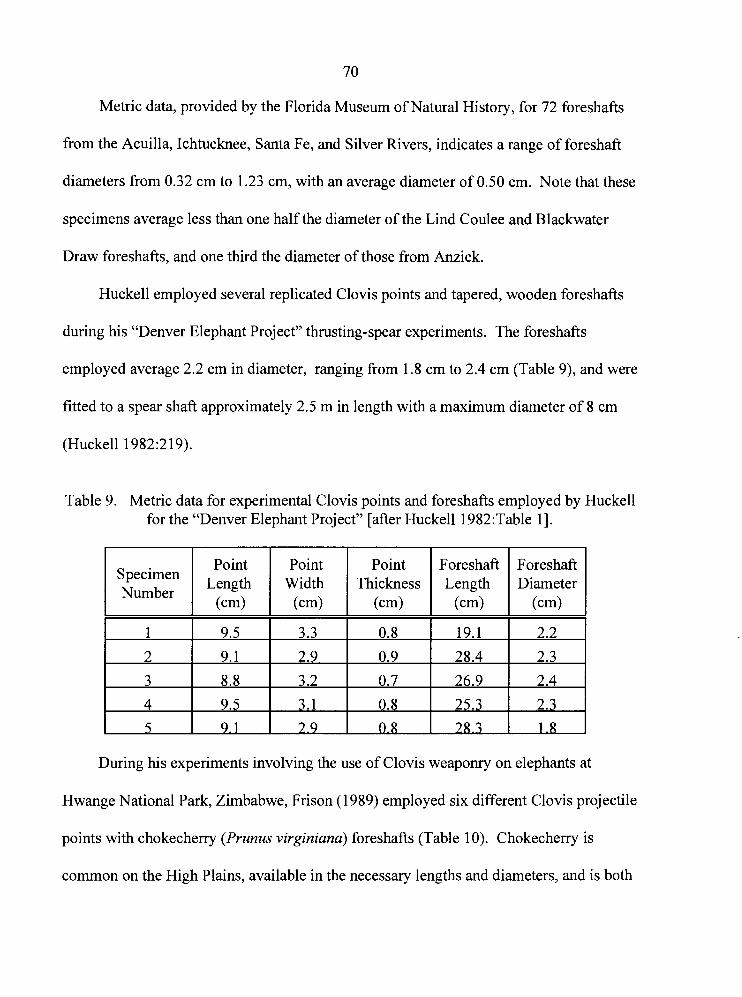
70
Metric data, provided by the Florida Museum of Natural History, for 72 foreshafts
from the Acuilla, Ichtucknee, Santa Fe, and Silver Rivers, indicates a range of foreshaft
diameters from 0.32 cm to 1.23 cm, with an average diameter of 0.50 cm. Note that these
specimens average less than one half the diameter of the Lind Coulee and Blackwater
Draw foreshafts, and one third the diameter of those from Anzick.
Huckell employed several replicated Clovis points and tapered, wooden foreshafts
during his "Denver Elephant Project" thrusting-spear experiments. The foreshafts
employed average 2.2 cm in diameter, ranging from 1.8 cm to 2.4 cm (Table 9), and were
fitted to a spear shaft approximately 2.5 m in length with a maximum diameter of 8 cm
(Huckell 1982:219).
Table 9. Metric data for experimental Clovis points and foreshafts employed by Huckell for the "Denver Elephant Project" [after Huckell 1982:Table 11.
Point Specimen
Length Number
(cm)
Point Width
(cm)
3.3
2.9
3.2
3.1
2.9
Point Thickness
(cm)
0.8
0.9
0.7
0.8
C).8
During his experiments involving the use of Clovis weaponry on elephants at
Hwange National Park, Zimbabwe, Frison (1 989) employed six different Clovis projectile
points with chokecherry (Prunus virginiana) foreshafts (Table 10). Chokecherry is
common on the High Plains, available in the necessary lengths and diameters, and is both
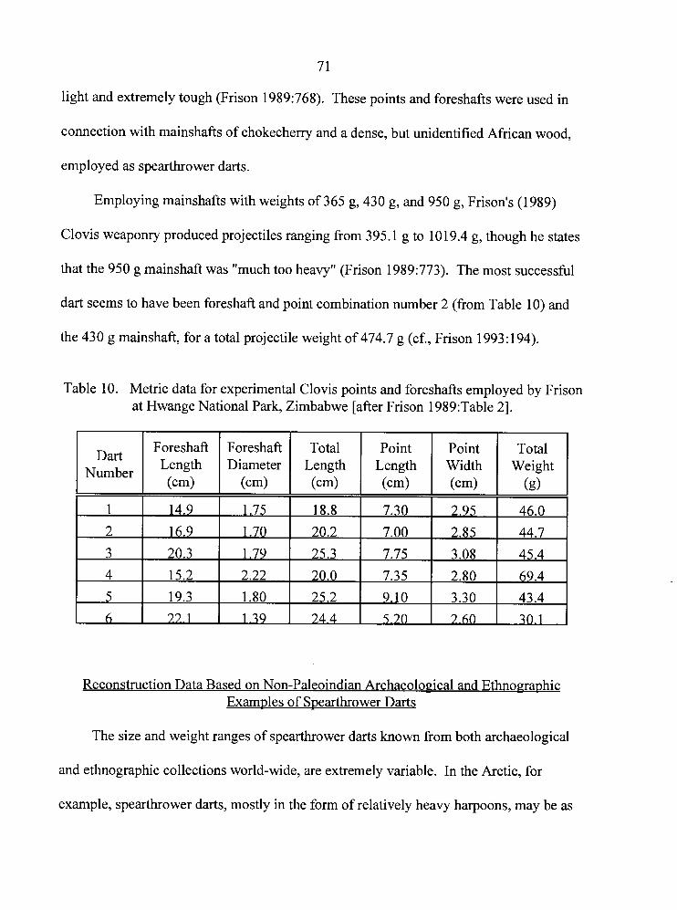
7 1
light and extremely tough (Frison 1989:768). These points and foreshafts were used in
connection with mainshafts of chokecherry and a dense, but unidentified African wood,
employed as spearthrower darts.
Employing mainshafts with weights of 365 g, 430 g, and 950 g, Frison's (1989)
Clovis weaponry produced projectiles ranging from 395.1 g to 1019.4 g, though he states
that the 950 g mainshaft was "much too heavy" (Frison 1989:773). The most successful
dart seems to have been foreshaft and point combination number 2 (from Table 10) and
the 430 g mainshaft, for a total projectile weight of 474.7 g (cf., Frison 1993: 194).
Table 10. Metric data for experimental Clovis points and foreshafts employed by Frison at Hwange National Park, Zimbabwe [after Frison 1989:Table 21.
Reconstruction Data Based on Non-Paleoindian Archaeological and Ethnographic Examples of Spearthrower Darts
Number
The size and weight ranges of spearthrower darts known from both archaeological
and ethnographic collections world-wide, are extremely variable. In the Arctic, for
example, spearthrower darts, mostly in the form of relatively heavy harpoons, may be as
Foreshaft Length (cm)
Foreshaft Diameter
(cm)
Total Length (cm)
Point Length (cm)
Point Width ( 4
Total Weight
(g>
72
short as 105 cm (Eskimo, mean = 124 cm). In contrast, Australian darts reach as much
as 330-340 cm in length (Aborigine, mean = 250 cm)(Stodiek 1993:211) and may weigh
in excess of 800 grams (Palter 1977:Figure 2).
A study of spearthrower dart sizes and weights, based on archaeological specimens
recovered from dry cave deposits in the American Great Basin and Southwest, was
recently conducted by Hutchings and Briichert (1 997):
Some of the lightest spearthrower darts have been recovered from dry cave deposits in the American Great Basin and the Southwest; finds from more than 130 sites noted several hundred dart fragments and several complete darts, which exhibit relative consistency in size, weight, and construction. These are relatively short at approximately 1 16 to 160 cm in length, and many, particularly those from Basketmaker deposits, would have weighed as little as 45 to 90 grams.
Similarly, Spencer (1974:Table 2) provides data for a replicated dart shaft based on
specimens recovered from dry cave sites in the Great Basin. The total weight of his dart
is given as "57 cm [sic]". I interpret Spencer's typographical error to indicate a weight of
57 g. This is consistent with basketmaker dart weights, and the alternative, 57 ounces
(1 61 6 g), assuming the numeric value is correct, is much too heavy
Spearthrower darts employed ethnographically by Australian Aborigines may be the
most variable of any region. Sizes and weights range from specimens comparable to
those of the Southwestern Basketmaker, to the largest known, iron-tipped specimens
which average 500 grams (Cundy 1989: 1 12). Metric data from an Australian sample of
293 ethnographic spearthrower darts was collected by Palter (1977). The average weight
of these darts was found to be 246.3 g (Palter 1977: 163). Unfortunately, while Palter
73
(1 977: 163) recorded an average dart length of 249.8 cm for the sample, no measures of
dart diameter were reported.
Metric data for the diameters of spearthrower dart shafts and foreshafts are available
from the existing literature for North American sites in the Southwest, Great Basin,
California, Mexico, Texas, and Florida (eg., Berry 1976; Cosgrove 1947; Cressman 1944;
Cressman and Krieger 1940; Dalley 1970, 1976; Fenenga and Heizer 194 1 ; Gilliland
1975; Guernsey 193 1 ; Guernsey and Kidder 192 1 ; Harrington 1933; Hattori 1982; Heizer
1938, 1942; Janetski 1980; Jennings 1957; Loud and Harrington 1929; Pendleton 1985;
Salls 1986; Taylor 1966; Tuohy 1982). This material offers several hundred examples of
complete darts and dart fragments from more than 155 sites. In many instances, the
metrics are provided by the author, though in some, diameters were derived from scale
photographs. To summarize these data, North American spearthrower dart mainshafts
recovered from archaeological contexts range from 0.8 cm to 1.9 cm in diameter. The
majority though, range from 0.9 cm to 1.3 cm in diameter. Likewise, foreshafts range
from 0.6 cm to 1.9 cm in diameter, but most are approximately 0.8 cm to 1.1 cm in
diameter. Based on these data, it is reasonable to suggest that a typical spearthrower dart
from this survey area would have a mainshaft diameter of 1.3 cm, and a foreshaft
diameter of 1.1 cm.
Modern spearthrower-hunter Steve Coleman, a well known and respected individual
in the use of prehistoric weaponry (e.g., Becker 1993), has researched the spearthrower
extensively. Having conducted hunts frequently for several years, he has become
extremely proficient in the weapon's use. Coleman prefers a dart of 221 cm length,
74
approximately 1.1 cm in diameter, with a Clovis-style lithic point between 20 g and 30 g,
for a total dart weight of 240 g (Coleman: personal communication; cf., Becker 1993:41).
Summary of Haft Diameter Data
Although the data indicate that spearthrower darts known from different parts of the
world vary significantly, several important characteristics are suggested. The data most
important to the experiments that follow are those concerning dart weight. Frison
(1989:773) states that his experimental 950 g mainshaft was too heavy, and preferred a
total dart weight of 474.7 grams for penetrating elephant hide.
A Paleoindian dart shaft modeled after Basketmaker specimens would be
inadequate for all but the smallest fluted points. Such a lightweight reed shaft would not
withstand the acceleration of a heavy Clovis point without flexing to the point of
breakage. In addition, according to Frison's (1989) experiment, it would not carry
sufficient mass to penetrate elephant hide.
The average dart weight of 246.3 g obtained by Palter (1 977: 163) from a large
Australian ethnographic sample is surprisingly close to the 240 g preference of practicing
hunter Steve Coleman. The effectiveness of Coleman's darts are aptly described by
Becker:
Penetration was about 42" through the hog . . . Never in my 30 years of bowhunting had I seen an arrow put a big game animal down for keeps as quickly as Steve's 3,000 grain [approximately 194gl dart had [Becker 1993 :42].
Although this account describes a slightly lighter dart, Becker notes that in hunting wild
boar, notably a large-game species, Coleman's darts often penetrate the animal
75
completely, whether through the chest cavity, or the shoulder. This has also been
observed while using lithic armatures (Co1eman:personal communication). While the
wild boars hunted by Coleman do not have the thick hide of an elephant, Becker's (1 993)
comparison between the performance of darts and arrows suggests that the dart is an
extremely effective weapon against large-game animals.
It was noted above that the weight of the replicated haft is of prime importance to
the experiments that follow, whereas the size is considered secondary. In most cases, the
size will have little effect as long as the lithic points are presented to the targets in a
reasonably realistic fashion. Gramly's (1984: 1 13) hypothesis that hafts at the Vail site
were 2.4-2.5 cm in diameter cannot be reasonably accepted as a norm for Clovis practice.
The widths of many finished Clovis points are less than this, though their effectiveness
can only be assumed based on the fact that they were indeed used. In such a large haft,
these points could not be presented to a target in a useful fashion since their lateral
margins would not be exposed for contact (see Hutchings 1991 :25).
The diameters of bone and ivory "foreshafts" reported from several Paleoindian
sites vary considerably. I am inclined to believe that many of these artifacts are not
foreshafts at all. The hafting model proposed by Lahren and Bonnichsen (l974:Figure 3)
appears clumsy and cumbersome, and the additional splint required to complete the haft
has never been demonstrated to have existed. Some of these artifacts are, however,
morphologically similar to Upper Paleolithic, Gravettian bevel-based bone points. The
most reasonable assessment, therefore, seems to be that of Hester, Lundelius, and Fryxell
(1972) and Sellards (1952) who identi@ the specimens from Blackwater Draw as bone
76
points. I do not discount the possibility that more than one type of artifact is represented
by this group of objects, perhaps having completely unrelated functions. For example,
Grarnly (1993:59) has speculated that bone rods recovered from the Richey Clovis Cache
in Washington may have been components of sled runners.
Employing the hypothesis that channel-flake scars reflect the haft-contact area for
Paleoindian armatures, one is again presented with a considerable range of hypothetical
haft widths. Of the samples examined average measures of Clovis channel-flake, and
channel-flake scars reflect a relatively narrow range of variation, from 1.2 cm to 1.7 cm.
The thrusting-spear experiments conducted by Huckell(1982) employed
significantly larger foreshafts than the preceding Clovis data suggests. Four of Huckell's
five foreshafts range from 2.2 cm to 2.4 cm., approaching the 2.4 cm to 2.5 cm diameter
of thrusting-spear shafts suggested by Gramly (1984). Huckell does note certain design
flaws related to the size and arrangement of his experimental mainshaft and foreshafts:
It was found that penetration of the spear was generally stopped at one of two locations on the composite spear: the juncture of the foreshaft with the mainshaft, or the binding securing the point to the foreshaft [Hucke111982:220].
These problems suggest that while the design may be sturdy, a smaller diameter foreshaft
and mainshaft would aid penetration. Logically, this suggests that dart shafts should also
be smaller. The subsequent experiment by Frison (1 989) employed slightly narrower
foreshafts, but most were still larger than the 1.2 cm to 1.7 cm diameter suggested by the
sample channel-flake data. It is not surprising then that in connection with similar
experiments Frison (1991 :295) later noted a tendency ". . . to underestimate the strength
77
and flexibility of a wooden foreshaft and the binding elements to the extent that they were
too bulky".
An important consideration for proper performance of a dart shaft is the ability of
the shaft to flex during the throw. A thick dart shaft with little ability to flex does not
transfer energy efficiently, resulting in a loss of speed. It is also much more difficult to
aim since the rotation of the spearthrower is transmitted directly to the shaft, rather than
offset by its flexure.
Based on this survey data, dart shafts and foreshafts of dry hemlock approximately
1.3 cm in diameter were chosen for the experiments employed in this research, except
where noted. These shafts produce an average completed "Clovis" dart weighing
approximately 240 g. Other dart weights varied according to the parameters of various
experiments, but generally ranged from approximately 82 g to 5458.
Effective Hunting Ranges
For the most part, ethnographic data concerning the effective range and accuracy of
the spearthrower is available only from Australia and the North American Arctic
(Hutchings and Briichert 1997). Most accounts reflect the fascination that ethnographers
held for the device and record long distance, competition-type throws. In most of these
cases it appears that distances were often estimated rather than measured. In addition,
where accuracy of the device was recorded, the observer's definition is often in question.
Since accuracy is a relative term, some minimal description of target size and range is
required, but is generally absent from the ethnographies. While some accounts claim that
7 8
the device has been used with some degree of accuracy up to approximately 64 metres,
the most reliable evidence suggests that the majority of successful throws in hunting
situations were at ranges between 10 m and 30 my and that accuracy falls off dramatically
beyond 27 m (Stodiek 1993:211; see also Falkenberg 1968: 15-38).
Data regarding practical hunting ranges and success rates are available from field
studies of spearthrower equipment used in modern hunting situations (Hutchings and
Briichert 1997). The hunts were conducted by Steve Coleman, an experienced
spearthrower hunter (see Becker 1993), who runs a wild-boar hunting operation in
Georgia, catering to hunters who use both the bow and the spearthrower.
Based on 109 field trials (5 1 hits, 58 misses) under normal hunting conditions in
both wooded and open environments, the data indicate that successful throws resulting in
fatal wounds or serious disablement range from 3 m to 46 my with an average of 15 m (s
= 8.5 m). Few throws beyond 23 m are successful. Misses ranged from 6 m to 54 m,
with an average of 24 m (s = 14.3 m) (Hutchings and Briichert 1997).
As target sizes increase, the effective range of the spearthrower increases only
slightly. This is because more massive muscle and skeletal structures usually protect
larger game, thus the need to hit vital organs becomes more critical. One would not
expect a mammoth, for example, to represent an easy target due to its heavy coat, thick
hide, and massive ribcage. Note also that long distance shots, or lobbing projectiles into a
herd of animals, unless launched in massive volleys into a very tightly packed herd, is
generally dismissed as an ineffective hunting method (e.g., Frison 1991 :297).
79
Based on this data, a distance of 15 m was selected to represent an average practical
spearthrower range.
Spearthrower Experiments
Most researchers agree that hunters generally prefer to limit the distance to their
target as much as possible since this allows a flatter trajectory, improved accuracy, and
greater chance of success. Despite this, a common error in spearthrower research has
been the calculation of projectile velocities from maximum throwing distance (e.g.,
Browne 1940; Butler 1975; Dickson 1985; Fenenga and Heizer 194 1 ; Grant 1979; Hill
1948; Howard 1974; Mau 1963; Peets 1960;Van Buren 1974), employing a basic vacuum
ballistics formula where velocity (v) is equal to the square-root of the product of the
distance thrown (d), and the acceleration of gravity (G):
Butler (1 975) has employed distance data derived from the works of Browne
(1 94O:2 13), Peets (1 960: 109), and Howard (1 974: 104), to compute dart velocities ranging
from 20.5 to 26.9 m/s. Similarly, Cotterell & Kamminga (1990:168) calculate that a
velocity greater than 3 1 m/s would be required to cast a dart 100 metres.
Tolley & Barnes (1 979: 162) found that the distance a dart could be thrown is more
a function of its aerodynamics than any property of the spearthrower: consider, for
example, that experienced baseball pitchers and javelin throwers routinely use lift to their
80
advantage. This suggests that velocity estimates derived from distance data are inadequate
for an accurate assessment of spearthrower performance. Simplified ballistics models
based on maximum throwing distance assume ideal trajectories, ignore aerodynamic
effects, and represent only an initial thrust rather than a downrange velocity representative
of hunt-related target ranges.
Dart and Javelin Velocity Measurements
Limited data representing measured dart velocities can be found in the existing
literature. Using both a radar gun and photographic equipment, Raymond (1986:Figure
15, Table 3) recorded average velocities of 25.3 and 21.6 m/s respectively, for a 70 g dart.
Also using photographic equipment, Tolley & Barnes measured velocities "in the
neighborhood of 40 meters per second (as measured 15 meters downrange), varying
plus or minus 6 meters per second" (1979: 172, emphasis added) for an unknown number
of darts which ranged from 68 to 190 g. Carrere & Lepetz (1988), employing a
photoelectric timing device, arrived at maximum velocities of 25.4 and 32.9 m/s for darts
of 150 and 50 g respectively, at a downrange distance of 2.5 m. Likewise, Bergman et al.
(1988) measured a velocity of 23 mls for a 195 g dart, using an MSI photoelectric device.
The considerable range of measured and calculated velocities reported in the current
literature, prompted an independent investigation of spearthrower dart velocity.
Velocity Experiments
Kinesiological studies of throwing technique indicate that more than half of a
spear's final velocity can be attributed to rotational acceleration from the wrist and
8 1
forearm (Cooper & Glassow 1968: 122); the same is true for the spearthrower dart. In
comparison, there is little velocity imparted by the straight-armed sweeping motion
described by Browne (1 94O:2 1 1).
The contribution of wrist rotation and the importance of proper throwing technique
was also evident in a series of tests conducted by Hutchings and Briichert (1 997), which
employed two international competition-level javelin throwers.
Some instruction and practice time was afforded, and although their performance improved rapidly with experience, an initial lack of familiarity limited their ability to adapt the style of wrist rotation required with the spearthrower, as opposed to the more familiar javelin. In the end, despite their proven, highly developed throwing abilities, the velocities achieved by an experienced spearthrower-user averaged 129 to 17 1 % greater than those of the javelin throwers [Hutchings and Briichert: 19971.
This demonstrated the need to develop a reasonable degree of proficiency with the
spearthrower prior to any investigation of spearthrower dart velocities. Several months,
constituting well over one hundred hours of technique development and target practice
were spent in preparation for the dart velocity experiments.
A photographic apparatus was designed to measure in-flight velocities both at
launch, and downrange at a distance of 15 m. The 15 m target range was chosen for three
reasons: (1) it represents the average successful hunting range derived from the Coleman
data (Hutchings and Briichert 1997), (2) it is within the range of successful hunting
throws recorded in the ethnographic literature, and (3) it is the same range tested by
Tolley and Barnes (1 979) during a similar experiment, and would therefore contribute to
an existing, albeit limited, body of data.
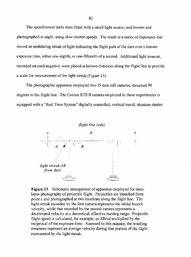
82
The spearthrower darts were fitted with a small light source, and thrown and
photographed at night, using slow shutter-speeds. The result is a series of exposures that
record an undulating streak of light indicating the flight path of the dart over a known
exposure time, either one-eighth, or one-fifteenth of a second. Additional light sources,
recorded on each negative, were placed at known distances along the flight line to provide
a scale for measurement of the light streak (Figure 13).
The photographic apparatus employed two 35 mm still cameras, mounted 90
degrees to the flight line. The Contax RTS I1 camera employed in these experiments is
equipped with a "Real Time System" digitally controlled, vertical travel, titanium shutter
flight line (cde)
I
i I I I
light streak AB ~ from dart ~
I
Figure 13. Schematic arrangement of apparatus employed for time- lapse photography of projectile flight. Projectiles are launched from point c and photographed at two locations along the flight line. The light-streak recorded by the first camera represents the initial launch velocity, while that recorded by the second camera represents a decelerated velocity at a theoretical, effective hunting range. Projectile flight speed is calculated, for example, as AB/cd multiplied by the reciprocal of the exposure time. Assessed in this manner, the resulting measures represent an average velocity during that portion of the flight represented by the light-streak.
8 3
mechanism governed by a high-precision quartz-crystal oscillator. A bench-test of the
Contax RTS I1 by Goldberg and Frank (1983), determined the percentage error associated
with a range of shutter speeds embracing those employed during these experiments.
During pre- and post-torture tests, Goldberg and Frank (1 983) measured a +I percent
(slow) error for the one-eighth second shutter speed, and a -6 percent (fast) error for the
one-fifteenth second shutter speed. By comparison, the ANSI shutter-accuracy standard
is +I- 25%, making most other types of 35 mm cameras unsuitable for this type of
research.
The tests employed seven different dart masses ranging from 82.9 g to 545.3 g
(Table 1 I). Darts were made from 1.3 cm diameter dry hemlock, and were of two-piece,
composite construction. The 122 cm mainshafts and 6 1 cm foreshafts were slightly
tapered on one end to accommodate a connector-sleeve made from a 7.6 cm length of
PVC tubing with an inside-diameter of 1.2 cm. Dart masses could be adjusted by adding
weighted metal sleeves to the shafts. The spearthrower employed in these experiments,
was a rigid, unweighted male type made of spruce, with double finger-loops of leather. It
is 65.4 cm in total length, 52.1 cm from the center of the finger-loops to the tip of the
bone engaging-hook, and weighs 149.5 grams.
The darts were launched in level flight, at an imaginary target approximately 1.5 m
to 2 m high, beyond the end of the flight-line. It is assumed that people employing the
spearthrower for subsistence would have the skills necessary to combine power and
accuracy. An imaginary target was therefore chosen over an actual target, to reduce any
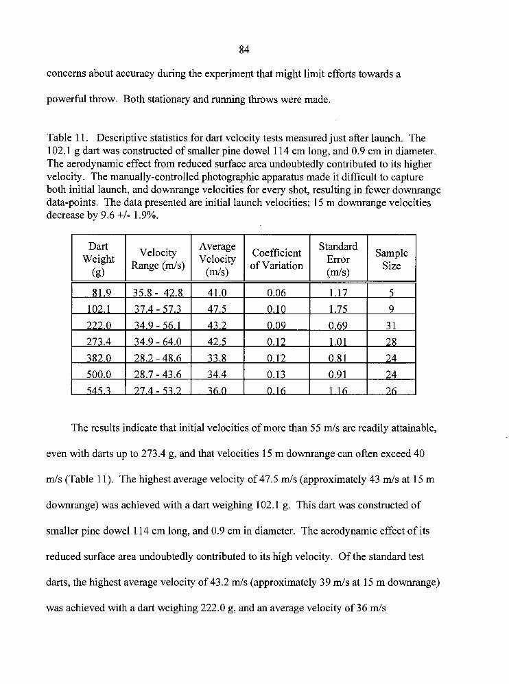
concerns about accuracy during the experiment that might limit efforts towards a
powerful throw. Both stationary and running throws were made.
Table 1 1. Descriptive statistics for dart velocity tests measured just after launch. The 102.1 g dart was constructed of smaller pine dowel 1 14 cm long, and 0.9 cm in diameter. The aerodynamic effect from reduced surface area undoubtedly contributed to its higher velocity. The manually-controlled photographic apparatus made it difficult to capture both initial launch, and downrange velocities for every shot, resulting in fewer downrange data-points. The data presented are initial launch velocities; 15 m downrange velocities decrease by 9.6 +I- 1.9%.
The results indicate that initial velocities of more than 55 m/s are readily attainable,
even with darts up to 273.4 g, and that velocities 15 m downrange can often exceed 40
Dart Weight
(g)
m/s (Table 1 I). The highest average velocity of 47.5 m/s (approximately 43 mls at 15 m
downrange) was achieved with a dart weighing 102.1 g. This dart was constructed of
smaller pine dowel 114 cm long, and 0.9 cm in diameter. The aerodynamic effect of its
Velocity Range ( d s )
reduced surface area undoubtedly contributed to its high velocity. Of the standard test
darts, the highest average velocity of 43.2 m/s (approximately 39 m/s at 15 m downrange) L
b i was achieved with a dart weighing 222.0 g, and an average velocity of 36 m/s I
Average Velocity
( d s )
Coefficient of Variation
Standard Error
(&s>
Sample Size
8 5
(approximately 32.5 m/s at 15 m downrange) was attained with the heaviest dart tested, at
545.3 g (Table 11). Downrange values at 15 m were calculated based on an average
velocity decrease of 9.6% * 1.9%.
The 222 g dart was the best matched projectile employed in these tests. That is to
say that its length, weight, and flexibility (i.e., "spine") were better suited to the properties
of the spearthrower, and the technique of the user (see Klopsteg 1943), and thus account
for its superior performance. Like an arrow on a bowstring, a dart flexes due to the
acceleration of the spearthrower during the throw, and continues to oscillate throughout
most of its flight, producing the undulating light streak recorded by the photographic
apparatus. The oscillation of an ideally matched dart allows it to spring away from the
engaging hook at a critical moment, after maximum acceleration of the spearthrower, that
adds to its overall efficiency (Cundy 1989:64-69; Perkins 1992).
In comparison, a similar study involving hand-thrown spears of the same materials,
dimensions, and of comparable weights indicates that velocities previously attributed to
spearthrower darts (cf., Butler 1975; Bergman, McEwen and Miller 1988; Carrkre and
i Lepetz 1988; Raymond 1986) are in fact attainable without the aid of that device at all
i (Table 12).
The velocities derived from these experiments were employed as benchmarks for
the lithic armature impact experiments which follow. A speed of 25 m/s was chosen to
represent javelin impact velocity at a theoretical downrange distance of 15 m, while
speeds of 35 m/s and 45 m/s were chosen to represent dart impact velocities at the same
range (although tests at 45 m/s were subsequently deemed unnecessary).
-. .-. -
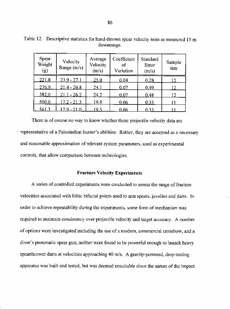
Table 12. Descriptive statistics for hand-thrown spear velocity tests as measured 15 m downrange.
There is of course no way to know whether these projectile velocity data are
Spear Weight
(g)
representative of a Paleoindian hunter's abilities. Rather, they are accepted as a necessary
and reasonable approximation of relevant system parameters, used as experimental
controls, that allow comparison between technologies.
Velocity Range ( d s )
Fracture Velocity Experiments
A series of controlled experiments were conducted to assess the range of fracture
velocities associated with lithic bifacial points used to arm spears, javelins and darts. In
order to achieve repeatability during the experiments, some form of mechanism was
required to maintain consistency over projectile velocity and target accuracy. A number
of options were investigated including the use of a modern, commercial crossbow, and a
diver's pneumatic spear gun; neither were found to be powerful enough to launch heavy
spearthrower darts at velocities approaching 40 m/s. A gravity-powered, drop-testing
apparatus was built and tested, but was deemed unsuitable since the nature of the impact
Average Velocity
(m/s)
Coefficient of
Variation
Standard Error ( d s )
Sample size
87
forces were not a reasonable approximation of the desired system. Other devices suffered
from similar problems, or were simply impractical.
Failing to locate and adapt any commercially available device, it was necessary to
design and build a shooting machine capable of launching heavy darts at a wide range of
velocities. The result was essentially a large, mounted crossbow with an adjustable draw
length. The main platform, supporting legs, and trigger mechanism were constructed
from heavy gauge aluminum by the Simon Fraser University Machine Shop. The
fibreglass bow limbs were constructed by bowyer Larry Courchaine of Checkmate
Archery, Abbottsford. The machine has a maximum draw weight of approximately 450
Ibs, and employs a bowstring of 2.38 mm diameter, 920 Ib test stainless steel aircraft
cable. A boat trailer winch, mounted at the rear of the main platform, is used to draw the
bowstring back to its locked position in the trigger mechanism. Dart velocities are
adjusted by altering the position of the trigger mechanism along the main platform, and
thereby altering the draw length.
In some experiments, where lower projectile velocities were required, or lighter
projectiles were used, a compound bow with a draw weight of 45 lbs was substituted for
the shooting machine. Relative consistency was achieved by marking the dart or arrow
shafts with the desired draw length necessary to produce a specific velocity.
Dart velocity was measured with a customized archery Speedtach chronometer,
manufactured by Custom Chronometer of Sumas, Washington. This photo-electric
device is designed to measure projectile velocities ranging from those of arrows, to small-
caliber firearms, and is accurate to one foot per second (approximately 0.3 mls). The
88
Speedtach was optimized for these experiments by the manufacturer to accurately
measure spear velocities as low as approximately 36 feet per second (1 1 mls), which are
normally below the Speedtach's accurate range.
In removing the projectiles from their normal system of operation and employing
the shooting machine, or compound bow, several important benefits were realized. The
most important of these was a relatively precise control over the flight path of the
projectile. A major disadvantage of the spearthrower is that at close range the device is
not very accurate. This is due largely to extreme flexure of the dart shaft during the initial
stages of the throw. After release the dart shaft continues to oscillate throughout its
flight, but at a greatly reduced amplitude after the first several metres. This created three
major problems which were solved by employing the shooting machine and compound
bow. First, the test range would need to be very long in order to give the dart shafts
enough time to settle into relatively stable flight. This also meant that the Speedtach
could be no closer than approximately 10 m since the oscillating shafts would strike the
sky-screen windows of the photo-sensors. This created a second problem in that, at that
distance, the Speedtach itself was at great risk of being severely damaged by an errant
shot. The third problem was that longer ranges would require the use of much larger
targets to prevent accidental damage to the test armatures.
The shooting machine does not seem to impart as much flexure to the dart shafts as
the spearthrower does, perhaps since the dart is restricted from reflexing by the platform
of the machine itself. Regardless, the accuracy of the system is sufficient to clear the sky-
screens of the Speedtach, and to target an area approximately five centimeters in diameter
8 9
at a range of four metres. The actual distance from the shooting machine to the target was
kept to a minimum, dictated by the lengths of the projectile and the Speedtach housing.
For example, the shooting machine and the target were both spaced approximately one
projectile length from opposite ends of the Speedtach. This permits the velocity of the
projectile to be measured after complete acceleration (i.e., after the projectile has
separated from the bowstring). For practical purposes, a little extra distance was afforded
between the Speedtach and target to prevent damage to the chronometer from a
rebounding projectile. In most cases, therefore, the range from bowstring to target was
limited to approximately three and one half meters. The stable flight, and accuracy of the
device, also permitted the use of much smaller targets. Except where otherwise noted,
targets for the controlled experiments consisted of several layers of fresh beef ribs
supported by straw-bail backstops.
A brief series of 12 trial shots employing a 230 g dart suggests that shooting
machine velocities are consistent to within a range of five feet per second at an average
velocity of 1 19.7 feet per second (36.5 d s ) . Recorded velocities ranged from 1 18 feet
per second (36.0 d s ) to 123 feet per second (37.5 d s ) (coefficient of variation = 0.01;
standard error = 0.41). Similar consistency was observed during the armature fracture
velocity experiments.
The darts employed in these experiments were identical to those used in the dart and
javelin velocity experiments. They were of two-piece construction consisting of a
fletched, 122 cm long mainshaft and a 40 cm foreshaft, both of 1.3 cm diameter dry
hemlock. A 7.6 cm length of PVC tubing with a 1.2 cm inside-diameter was used to
90
connect the slightly tapered mainshafts and foreshafts. When required, weights were
made from various lengths of 1.35 cm inside-diameter copper tubing, slipped over the
foreshaft and shaft, and secured with friction tape.
During the production of dart armatures, the aim was to fashion fluted Clovis point
replicas. Since a large number of points were necessary to complete these experiments,
rather than discard usable points that did not conform with the Clovis template due to
mistakes during manufacture, a variety of styles and sizes were ultimately employed. In
addition, points were often recycled after being used and damaged, producing smaller
points, sometimes fluted, sometimes not. All spear, javelin, and dart armatures were
fashioned from Glass Butte obsidian.
Results of the Dart Armature Lithic Fracture Velocity Tests
Darts ranging from 166.7 g to 295.6 g (2 = 243.8 g) were employed for this series
of projectile armature fracture velocity experiments. Projectile velocities for the dart tests
averaged 35.6 mls (s = 1.44 m/s; coefficient of variation = 0.04). Kinetic energies ranged
from 116.5 Joules to 165.1 Joules (x = 147.0 Joules). Fracture velocity data recovered
from 53 dart armatures (Tables 13 and 14) produced dl C, ratios ranging from 0.12 to
0.58, indicating fracture velocities spanning the rapid (38%) and dynamic (62%) loading
rate regimes (Figure 14). Summary statistics for dart armature fracture velocities are
presented in Table 15. The distribution of fracture velocities associated with dart impacts
is presented in Figure 15.
9 1
The fact that high-speed projectile impacts do not always produce dynamic regime
fractures indicates that the documenting of fracture velocity data for a single point may be
insufficient to identify the technological cause of a fracture. Note that the CIC, ratios
derived from the dart tests which reflect rapid loading rates actually span the full range of
fracture velocities associated with stone tool manufacture. This suggests that the impact
fracturing of lithic projectiles is a complex process which involves more than just those
fractures caused by the extreme force of sudden impact. In fact, an examination of highly
fragmented points suggests that a series of subsequent fractures may occur after the initial
impact. These may range from percussion fractures to actual pressure fractures as broken
and shattered armature fragments are pressed into one another during the later stages of
target penetration. It is, therefore, theoretically possible to document a broad range of
CIC, ratios from different fracture surfaces among the fragments of a single dart
armature that might span the entire range of fracture velocities associated with dart
impacts.
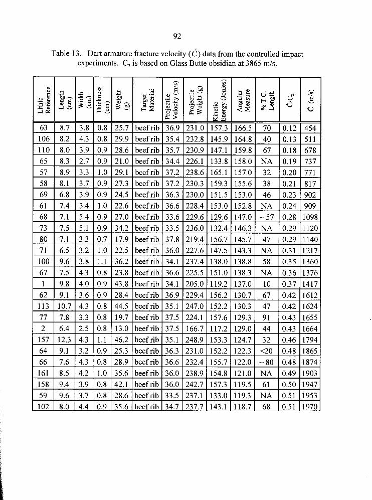
92
Table 13. Dart armature fracture velocity (6 ) data from the controlled impact experiments. C, is based on Glass Butte obsidian at 3865 m/s.
- m
Y .-
c- 2
beef rib beef rib beef rib beef rib beef rib beef rib beef rib beef rib beef rib beef rib beef rib beef rib beef rib beef rib
beef rib beef rib beef rib beef rib beef rib beef rib beef rib beef rib beef rib beef rib beef rib beef rib
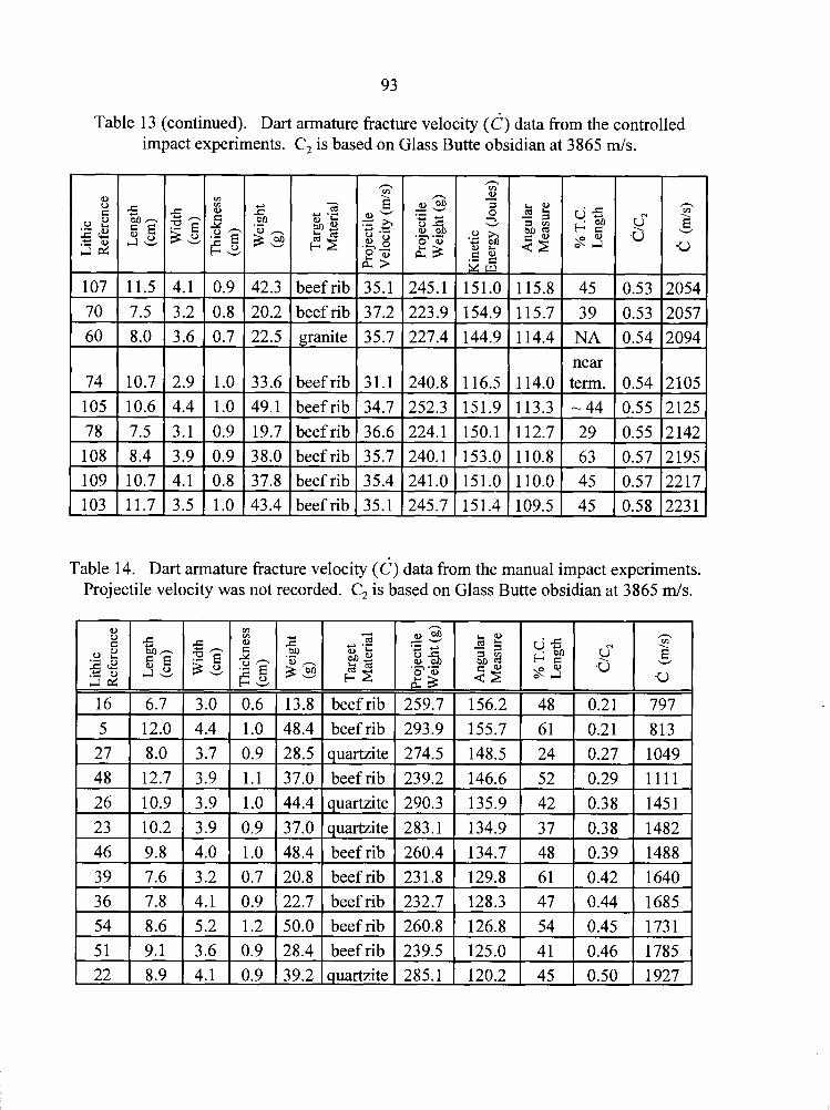
Table 13 (continued). Dart armature fracture velocity (6 ) data from the controlled impact experiments. C, is based on Glass Butte obsidian at 3865 mls.
- --
beef rib beef rib granite
beef rib beef rib beef rib
114.4 NA 0.54 near
114.0 term. 0.54 113.3 - 44 0.55 112.7 29 0.55 110.8 63 0.57 beef rib
beef rib beef rib
Table 14. Dart armature fracture velocity (c) data from the manual impact experiments. Projectile velocity was not recorded. C, is based on Glass Butte obsidian at 3865 mls.
beef rib 1 259.7 1 156.2 beef rib 1 293.9 1 155.7
beef rib 1 260.8 1 126.8
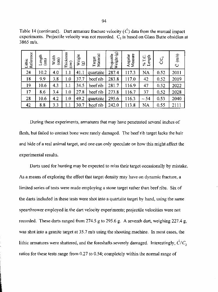
Table 14 (continued). Dart armature fracture velocity (c) data from the manual impact experiments. Projectile velocity was not recorded. C, is based on Glass Butte obsidian at 3865 m/s.
During these experiments, armatures that may have penetrated several inches of
flesh, but failed to contact bone were rarely damaged. The beef rib target lacks the hair
and hide of a real animal target, and one can only speculate on how this might affect the
experimental results.
Darts used for hunting may be expected to miss their target occasionally by mistake.
As a means of exploring the effect that target density may have on dynamic fracture, a
limited series of tests were made employing a stone target rather than beef ribs. Six of
the darts included in these tests were shot into a quartzite target by hand, using the same
spearthrower employed in the dart velocity experiments; projectile velocities were not
recorded. These darts ranged from 274.5 g to 295.6 g. A seventh dart, weighing 227.4 g,
was shot into a granite target at 35.7 m/s using the shooting machine. In most cases, the
lithic armatures were shattered, and the foreshafts severely damaged. Interestingly, dlc2
ratios for these tests range from 0.27 to 0.54; completely within the normal range of
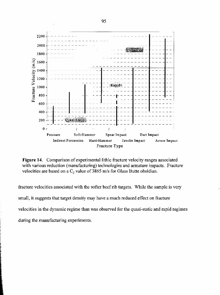
I I I I I I I
Pressure Soft-Hammer Spear Impact Dart Impact
Indirect Percussion Hard-Hammer Javelin Impact Arrow Impact
Fracture Type
Figure 14. Comparison of experimental lithic fracture velocity ranges associated with various reduction (manufacturing) technologies and armature impacts. Fracture velocities are based on a C, value of 3865 mls for Glass Butte obsidian.
fracture velocities associated with the softer beef rib targets. While the sample is very
small, it suggests that target density may have a much reduced effect on fracture
velocities in the dynamic regime than was observed for the quasi-static and rapid regimes
during the manufacturing experiments.
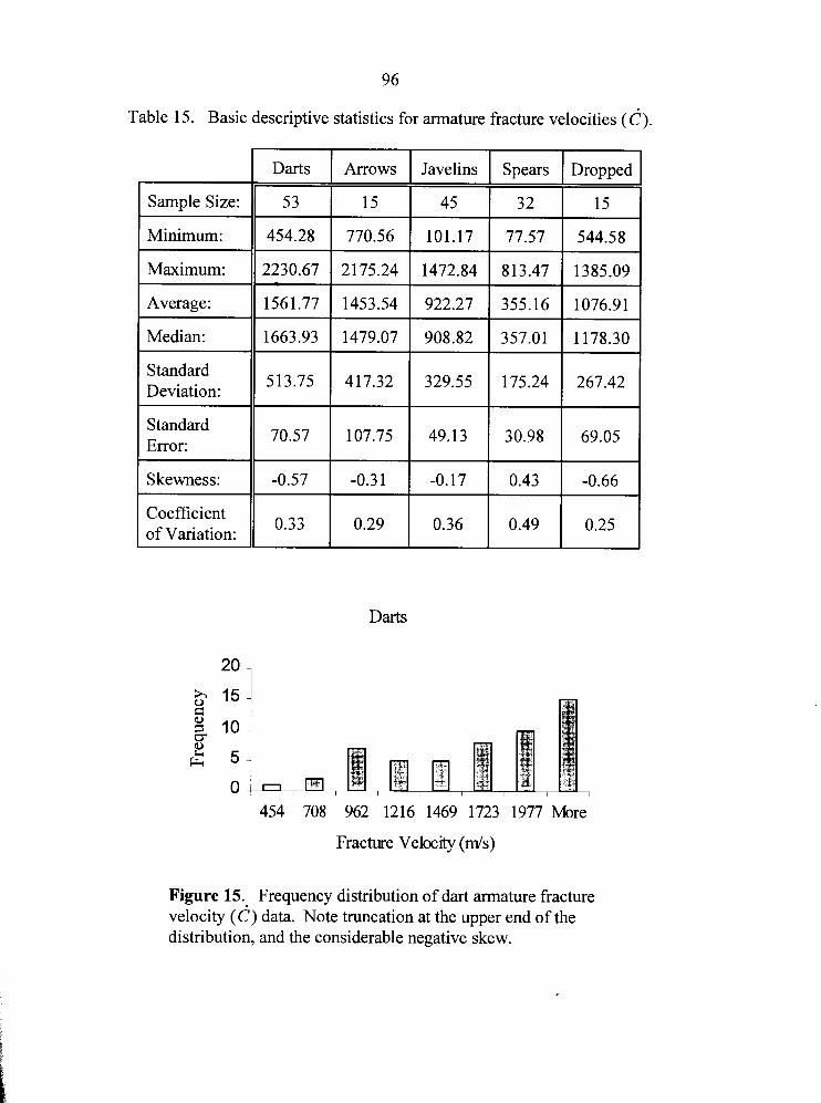
Table 15. Basic descriptive statistics for armature fracture velocities (c).
Darts Arrows Javelins Spears Dropped
3 2 15 Sample Size:
Minimum:
Maximum:
Average:
Median:
Standard Deviation:
513.75 417.32 329.55 175.24 267.42
Standard Error:
70.57 107.75 49.13 30.98 69.05
Skewness: -0.57 -0.3 1 -0.17 0.43 -0.66
Coefficient I 0.33 of Variation:
0.29 0.36 0.49 0.25
Darts
454 708 962 1216 1469 1723 1977 More
Fracture Veloclty ( d s )
Figure 15. Frequency distribution of dart armature fracture velocity (6) data. Note truncation at the upper end of the distribution, and the considerable negative skew.
Results of the Javelin Armature Lithic Fracture Velocitv Tests
Javelins ranging from 137.4 g to 296.4 g (x = 192.7 g) were employed for this
series of projectile armature fracture velocity experiments. Projectile velocities for the
javelin tests averaged 25.1 d s (s = 0.57 d s ; coefficient of variation = 0.02). Kinetic
energies ranged from 43.3 Joules to 97.0 Joules (x = 60.8 Joules). Fracture velocity data
recovered from 45 javelin armatures (Table 16) produced CIC, ratios ranging from 0.03
to 0.38, indicating fracture velocities spanning the quasi-static (4.4%), rapid (91.2%), and
dynamic (4.4%) loading rate regimes (Figure 14). Notably, only two javelin armatures
produced fracture velocities in the dynamic regime, and both were borderline, with CIC,
ratios of 0.38. Summary statistics for javelin armature fracture velocities are presented in
Table 15. The distribution of fracture velocities associated with javelin impacts is
presented in Figure 16.
As with the dart tests, a series of 10 shots were made employing denser targets of
granite and quartzite rather than beef ribs. These javelins ranged from 145.8 g to 242.2 g,
i and were fired under controlled conditions at velocities averaging 24.9 d s . In most I
cases, the lithic armatures were shattered, and the foreshafts severely damaged. The
dlC, ratios for these tests range from 0.17 to 0.38, which is within the normal range of
javelin armature fracture velocities associated with the softer beef rib targets. This again
suggests that target density may have a reduced effect on fracture velocities even at the
upper range of the rapid regime. More importantly, it suggests that regardless of the
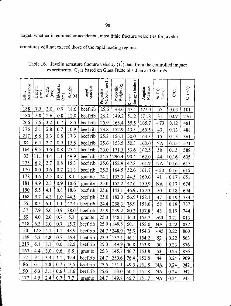
98
target, whether intentional or accidental, most lithic fracture velocities for javelin
armatures will not exceed those of the rapid loading regime.
Table 16. Javelin armature fracture velocity (c) data from the controlled impact experiments. C, is based on Glass Butte obsidian at 3865 d s .
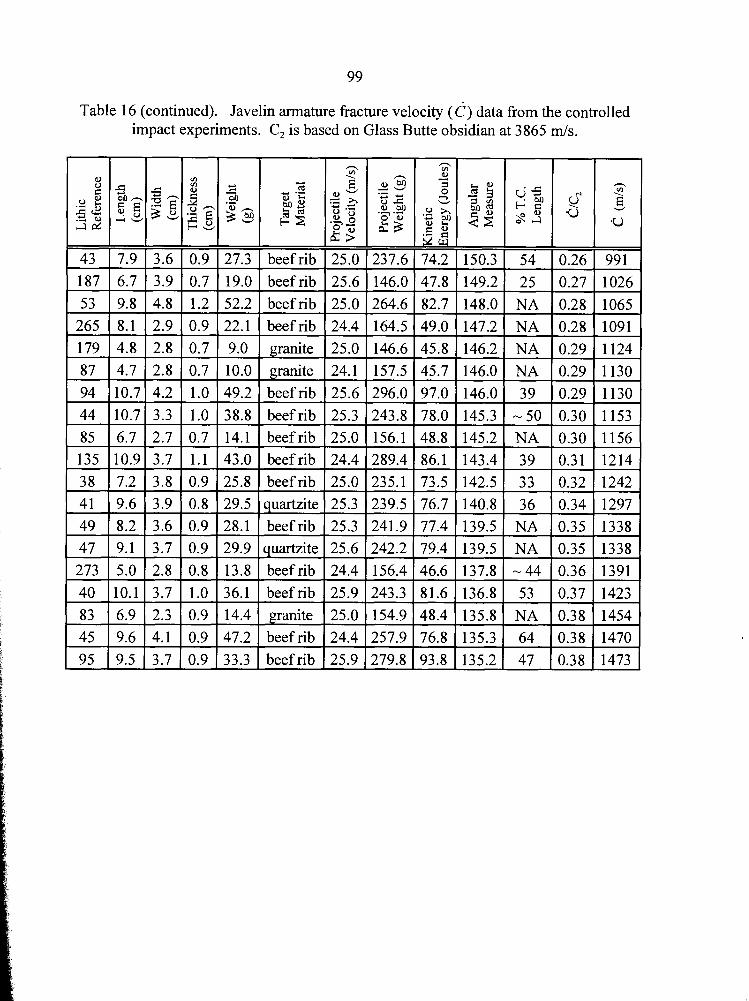
Table 16 (continued). Javelin armature fracture velocity (d) data from the controlled impact experiments. C, is based on Glass Butte obsidian at 3865 d s .
3.6 0.9 27.3 beefrib 25.0 237.6 74.2 150.3 54 0.26 9 9 1 3.9 0.7 19.0 beefrib 25.6 146.0 47.8 149.2 25 0.27 1026 4.8 1.2 52.2 beefrib 25.0 264.6 82.7 148.0 NA 0.28 1065 2.9 0.9 22.1 beefrib 24.4 164.5 49.0 147.2 NA 0.28 1091 2.8 1 0.7 1 9.0 1 granite ( 25.0 ( 146.6 1 45.8 1 146.2 1 NA 1 0.29 1 1124
3.9 0.8 29.5 quartzite 25.3 239.5 76.7 140.8 36 0.34 1297 3.6 0.9 28.1 beefrib 25.3 241.9 77.4 139.5 NA 0.35 1338 3.7 0.9 29.9 auartzite 25.6 242.2 79.4 139.5 NA 0.35 1338 2.8 0.8 13.8 beefrib 24.4 156.4 46.6 137.8 -44 0.36 1391 3.7 1.0 36.1 beefrib 25.9 243.3 81.6 136.8 53 0.37 1423 2.3 0.9 14.4 granite 25.0 154.9 48.4 135.8 NA 0.38 1454 4.1 0.9 47.2 beefrib 24.4 257.9 76.8 135.3 64 0.38 1470 3.7 0.9 33.3 beefrib 25.9 279.8 93.8 135.2 47 0.38 1473
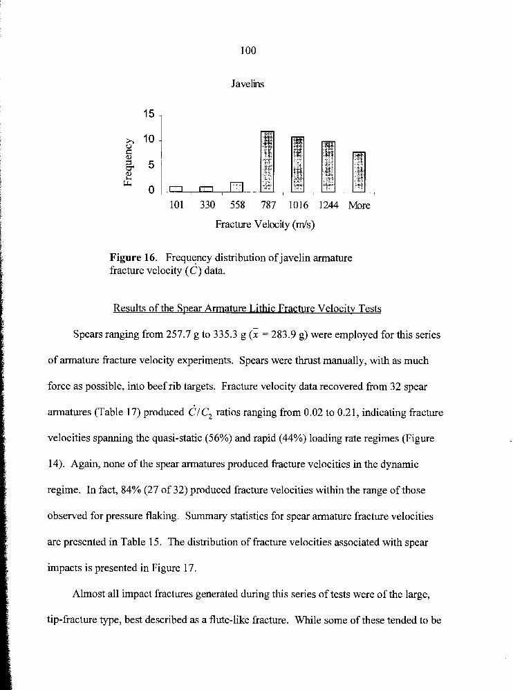
Javelins
101 330 558 787 1016 1244 More
Fracture Velocrty (rnls)
Figure 16. Frequency distribution of javelin armature fracture velocity ( d ) data.
Results of the Spear Armature Lithic Fracture Velocity Tests
Spears ranging from 257.7 g to 335.3 g (x = 283.9 g) were employed for this series
of armature fracture velocity experiments. Spears were thrust manually, with as much
force as possible, into beef rib targets. Fracture velocity data recovered from 32 spear
armatures (Table 17) produced dl C, ratios ranging from 0.02 to 0.2 1, indicating fracture
velocities spanning the quasi-static (56%) and rapid (44%) loading rate regimes (Figure
14). Again, none of the spear armatures produced fracture velocities in the dynamic
regime. In fact, 84% (27 of 32) produced fracture velocities within the range of those
observed for pressure flaking. Summary statistics for spear armature fracture velocities
are presented in Table 15. The distribution of fracture velocities associated with spear
impacts is presented in Figure 17.
Almost all impact fractures generated during this series of tests were of the large,
tip-fracture type, best described as a flute-like fracture. While some of these tended to be
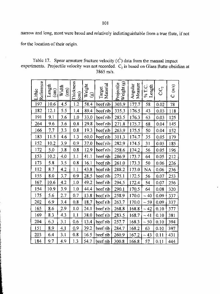
narrow and long, most were broad and relatively indistinguishable from a true flute, if not
for the location of their origin.
Table 17. Spear armature fracture velocity ( 6 ) data from the manual impact experiments. Projectile velocity was not recorded. C, is based on Glass Butte obsidian at
3865 rnls.
0 V1 n
0 V1 fz 5 8 0 : m - g T 3 0 - .3 0,
3 s a d j g 3 z a 8 + b .3
t - . v
197 10.6 4.5 1.2 58.4 beefrib 303.9 177.7 58 0.02 78 12.1 1 5.5 1 1.4 1 89.4 1 beef rib 1 335.3 1 176.5 1 43 1 0.03 1 118 1
191 9.1 3.6 1.0 33.0 beef rib 283.5 176.3 63 0.03 125
264 9.6 3.6 0.8 29.8 beefrib 271.8 175.7 68 0.04 145
166 7.7 3.3 0.8 19.3 beefrib 263.9 175.5 50 0.04 152
183 11.5 4.6 1.3 60.0 beefrib 311.3 174.7 35 0.05 179
1 152 ( 10.2 ( 3.9 1 0.9 1 37.0 1 beef rib 1 282.9 1 174.5 1 3 1 1 0.05 1 185 1
beefrib 1 268.8 (168.8 1 --42 k 1 0
1 184 1 9.7 1 4.9 1 1.3 (54.7 (beefrib) 300.8 1166.8 1 57 10.11 1444 1
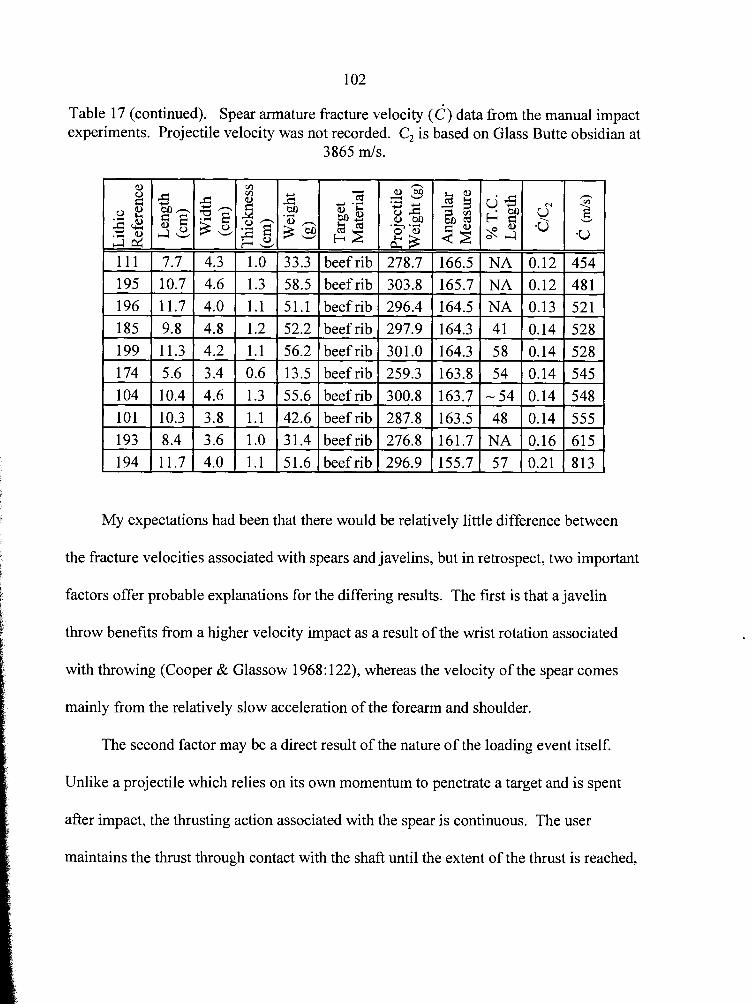
Table 17 (continued). Spear armature fracture velocity ( 6 ) data from the manual impact experiments. Projectile velocity was not recorded. C, is based on Glass Butte obsidian at
1.0 1 33.3 1 beef rib 1 278.7 1.3 1 58.5 1 beef rib 1 303.8 1.1 51.1 beefrib 296.4 * 1.1 56.2 beefrib 301.0 0.6 13.5 beefrib 259.3 1.3 55.6 beef rib 300.8 1.1 42.6 beef rib 287.8 , 1.0 1 3 1.4 1 beef rib 1 276.8 1.1 1 51.6 1 beefrib 1 296.9
My expectations had been that there would be relatively little difference between
the fracture velocities associated with spears and javelins, but in retrospect, two important
factors offer probable explanations for the differing results. The first is that a javelin
throw benefits from a higher velocity impact as a result of the wrist rotation associated
with throwing (Cooper & Glassow 1968: 122), whereas the velocity of the spear comes
mainly from the relatively slow acceleration of the forearm and shoulder.
The second factor may be a direct result of the nature of the loading event itself.
Unlike a projectile which relies on its own momentum to penetrate a target and is spent
after impact, the thrusting action associated with the spear is continuous. The user
maintains the thrust through contact with the shaft until the extent of the t h s t is reached,
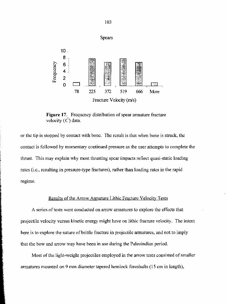
103
Spears
78 225 372 519 666 More
Fracture Velocrty ( d s )
Figure 17. Frequency distribution of spear armature fracture velocity ( 6 ) data.
or the tip is stopped by contact with bone. The result is that when bone is struck, the
contact is followed by momentary continued pressure as the user attempts to complete the
thrust. This may explain why most thrusting spear impacts reflect quasi-static loading
rates (i.e., resulting in pressure-type fractures), rather than loading rates in the rapid
regime.
Results of the Arrow Armature Lithic Fracture Velocity Tests
A series of tests were conducted on arrow armatures to explore the effects that
projectile velocity versus kinetic energy might have on lithic fracture velocity. The intent
here is to explore the nature of brittle fracture in projectile armatures, and not to imply
that the bow and arrow may have been in use during the Paleoindian period.
Most of the light-weight projectiles employed in the arrow tests consisted of smaller
armatures mounted on 9 mm diameter tapered hemlock foreshafts (1 5 cm in length),
104
connected to 9 rnrn diameter socketed pine shafts (80 cm in length). Others were
mounted directly to the pine shafts (80 cm in length). Completed arrows ranged from
44.5 g to 55.8 g (x = 49.8 g) and were fired into beef rib targets with a 45 lb draw weight
compound bow. Projectile velocities ranged from 33.5 m/s to 46.6 m/s (x = 39.2 d s ) .
Kinetic energies ranged from 30.0 Joules to 48.3 Joules (x = 38.2 Joules). Fracture
velocity data recovered from 15 arrow armatures (Table 18) produced CIC, ratios
ranging from 0.20 to 0.56, indicating fracture velocities spanning the rapid (46.7%) and
dynamic (53.3%) loading rate regimes (Figure 14). Summary statistics for arrow
armature fracture velocities are presented in Table 15. The distribution of fracture
velocities associated with arrow impacts is presented in Figure 18.
Fracture velocity data recovered from the arrow armatures compare favorably with
that of the darts. Considering that kinetic energies for the arrows were less than one third
that of the darts, and approximately half that of the javelins, one must conclude that
impact velocity is the essential variable affecting fracture velocity, rather than kinetic
energy.
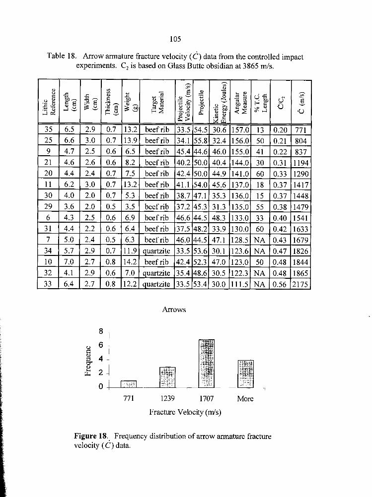
Table 18. Arrow armature fracture velocity ( 6 ) data from the controlled impact experiments. C, is based on Glass Butte obsidian at 3865 d s .
beef rib beef rib beef rib beef rib beef rib beef rib beef rib
beef rib beef rib beef rib beef rib quartzite beef rib quartzite quartzite
Arrows
77 1 1239 1707 More
Fracture Velocrty ( d s )
Figure 18. Frequency distribution of arrow armature fracture velocity ( d ) data.
Results of the Dropped Armature Lithic Fracture Velocity Tests
It is reasonable to expect that projectile armatures, either hafted or un-hafted, were
occasionally subjected to accidental abuse by their prehistoric owners. The most
probable area of impact for a hafted armature would be the distal lateral margins and tip,
and this may result in damage morphologically indistinguishable from intentional use. A
series of tests were therefore conducted to explore the effects of accidental dropping of
armatures onto a hard surface.
All armatures were hafted as spearthrower darts, and dropped from a height of two
metres, tip first, onto an andesite boulder. Their velocity upon impact was estimated at
6.3 mls. Total weights ranged from 225.3 g to 244.6 g (x = 232.1 g), and their kinetic
energies ranged from 4.4 Joules to 4.8 Joules. Most damage was in the form of classic tip
fractures; a single armature was shattered, and two suffered burinated lateral margins.
Fracture velocity data recovered from 15 armatures (Table 19) produced dl C, ratios
ranging from 0.14 to 0.36, indicating fracture velocities within the rapid loading rate
regime. Summary statistics for dropped armature fracture velocities are presented in
Table 15. The distribution of fracture velocities associated with drop impacts is presented
in Figure 19.
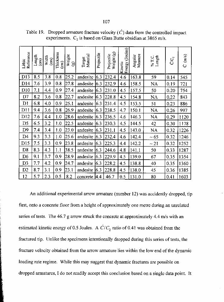
Table 19. Dropped armature fracture velocity (c) data from the controlled impact experiments. C, is based on Glass Butte obsidian at 3865 d s .
I I I
125.2 1 andesite 16.3
8.2 1 concrete 14.4
An additional experimental arrow armature (number 12) was accidently dropped, tip
first, onto a concrete floor from a height of approximately one metre during an unrelated
series of tests. The 46.7 g arrow struck the concrete at approximately 4.4 m/s with an
estimated kinetic energy of 0.5 Joules. A CIC, ratio of 0.41 was obtained from the
fractured tip. Unlike the specimens intentionally dropped during this series of tests, the
fracture velocity obtained from the arrow armature lies within the low end of the dynamic
loading rate regime. While this may suggest that dynamic fractures are possible on
dropped armatures, I do not readily accept this conclusion based on a single data point. It
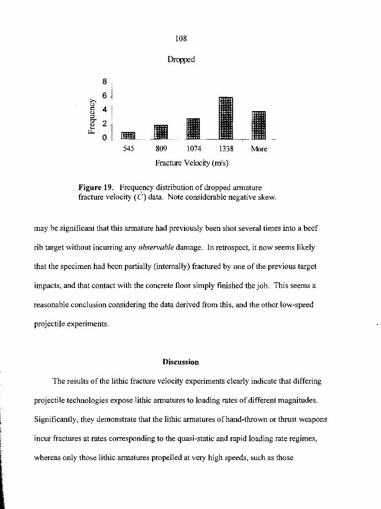
lo8
Dropped
545 809 1074 1338 More
Fracture VelocQ (mk)
Figure 19. Frequency distribution of dropped armature fracture velocity (6) data. Note considerable negative skew.
may be significant that this armature had previously been shot several times into a beef
rib target without incurring any observable damage. In retrospect, it now seems likely
that the specimen had been partially (internally) fractured by one of the previous target
impacts, and that contact with the concrete floor simply finished the job. This seems a
reasonable conclusion considering the data derived from this, and the other low-speed
projectile experiments.
Discussion
The results of the lithic fracture velocity experiments clearly indicate that differing
projectile technologies expose lithic armatures to loading rates of different magnitudes.
Significantly, they demonstrate that the lithic armatures of hand-thrown or thrust weapons
incur fractures at rates corresponding to the quasi-static and rapid loading rate regimes,
whereas only those lithic armatures propelled at very high speeds, such as those
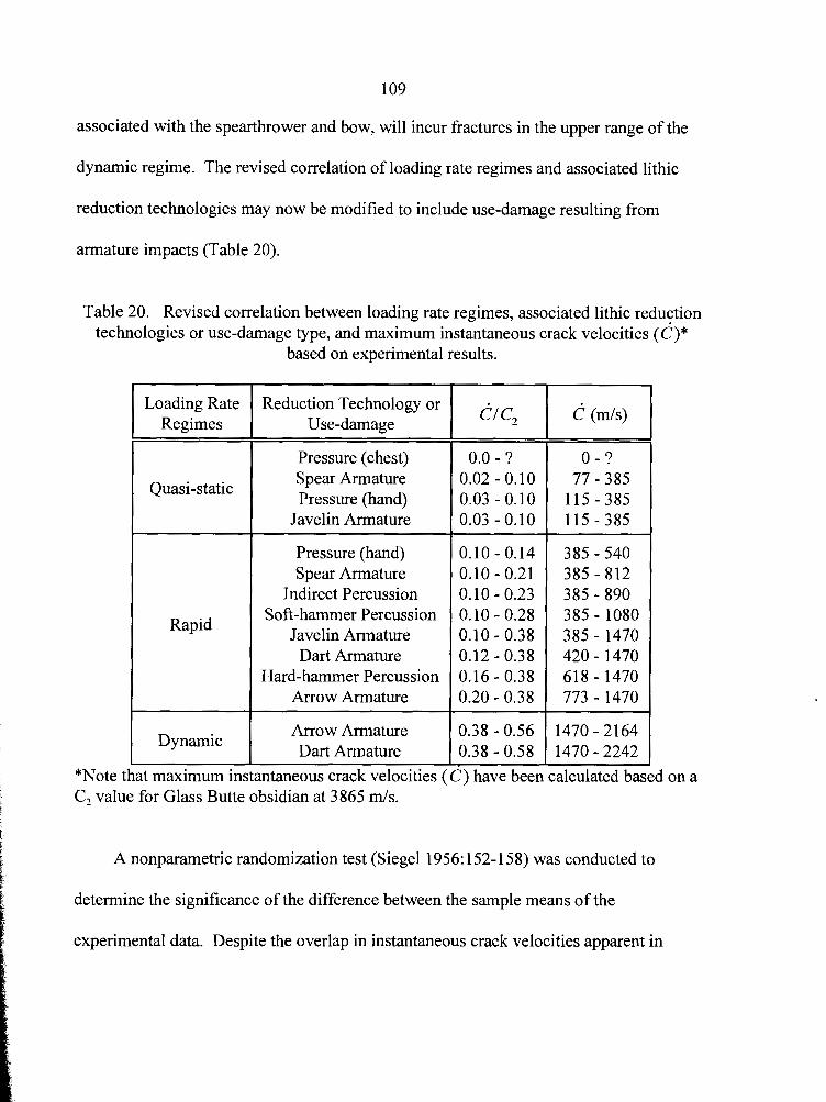
109
associated with the spearthrower and bow, will incur fractures in the upper range of the
dynamic regime. The revised correlation of loading rate regimes and associated lithic
reduction technologies may now be modified to include use-damage resulting from
armature impacts (Table 20).
Table 20. Revised correlation between loading rate regimes, associated lithic reduction technologies or use-damage type, and maximum instantaneous crack velocities (c)*
based on experimental results.
Loading Rate Regimes
Rapid
Dynamic
that maximum
Reduction Technology or Use-damage
Pressure (chest) Spear Armature Pressure (hand)
Javelin Armature
Pressure (hand) Spear Armature
Indirect Percussion Soft-hammer Percussion
Javelin Armature Dart Armature
Hard-hammer Percussion Arrow Armature
Arrow Armature Dart Armature I 7 ) have been calculated based on a
C, value for Glass Butte obsidian at 3865 rnls.
A nonparametric randomization test (Siege1 1956: 152- 158) was conducted to
determine the significance of the difference between the sample means of the
experimental data. Despite the overlap in instantaneous crack velocities apparent in
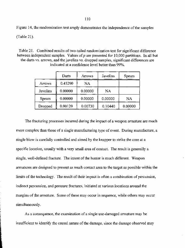
Figure 14, the randomization test amply demonstrates the independence of the samples
(Table 21).
Table 21. Combined results of two-tailed randomization test for significant difference between independent samples. Values o fp are presented for 10,000 partitions. In all but
the darts vs. arrows, and the javelins vs. dropped samples, significant differences are indicated at a confidence level better than 99%.
I Darts 1 Arrows ( Javelins I Spears I
I Javelins 11 0.00000 ( 0.00000 1 NA ( I
I
I Spears 11 0.00000 ( 0.00000 1 0.00000 ( NA I
Arrows
1 Dropped 11 0.00120 1 0.00730 1 0.10440 1 0.00000 1
The fracturing processes incurred during the impact of a weapon armature are much
0.45290
more complex than those of a single manufacturing type of event. During manufacture, a
NA
single blow is carefully controlled and aimed by the knapper to strike the core at a
specific location, usually with a very small area of contact. The result is generally a
single, well-defined fracture. The intent of the hunter is much different. Weapon
armatures are designed to present as much contact area to the target as possible within the
limits of the technology. The result of their impact is often a combination of percussion,
indirect percussion, and pressure fractures, initiated at various locations around the
margins of the armature. Some of these may occur in sequence, while others may occur
simultaneously.
As a consequence, the examination of a single use-damaged armature may be
insufficient to identify the causal nature of the damage, since the damage observed may
not be the result of an event
11 1
which accurately reflects the maxirr lum loading rate normally
expected for that armature type. For example, experimental point number 69 is an
obsidian Clovis replica employed as a dart armature, that incurred a large, flute-like tip
fracture resulting from impact with bone at 36.3 mls; experimental point number 163 is
also an obsidian Clovis replica, though employed as a javelin armature, that incurred a tip
fracture resulting from impact with bone at 25.3 m/s. The tip fractures of both armatures
reveal fractures with CIC, ratios of 0.23, indicating fracture velocities of approximately
889 rnls. Both of these fall within the range of fracture velocities observed for soft- and
hard-hammer percussion, as well as dart, javelin, and arrow armature impacts, or even
accidentally dropped specimens! One cannot reliably assign these fractures to any
specific cause based on their known loading rates, although pressure flaking may be ruled
out since their loading rates exceed that known for pressure reduction.
The cause of a specific fracture, based solely on knowledge of the precursory
loading rate, can only be assigned through exclusion. That is to say, for example, that if a
fracture velocity of 1700 m/s were obtained from a given armature constructed from a
material with properties similar to Glass Butte obsidian, one may reasonably conclude:
(1) that the fracture was not the result of any known manufacturing process; (2) that it
was caused by a high-velocity impact; and therefore (3) it was the result of use as an
arrow or dart armature. Due to its dynamic loading rate, the armature is excluded from
consideration of any other causes of fracture. Given also, that fracture velocities are a
non-subjective, metric determination, a single, reliable measure is all that is necessary for
the armature in this example to be confidently assigned as an arrow or dart armature.
Summary
An examination of spearthrower dart metric data derived from both ethnographic
and archaeological sources, combined with performance studies, suggests that effective
spearthrower darts may vary greatly in size and weight. While there are no empirical data
regarding Clovis fluted-point haft sizes, a reasonable approximation of 1.3 cm diameter,
and 240 grams total projectile weight was suggested for hypothetical Clovis dart replicas.
Similarly, ethnographic and ethno-archaeological research suggested that the
effective range of the spearthrower is approximately 15 m. These size and range data
formed the basis of several series of experiments designed to assess the range of
velocities associated with various darts and javelins. It was demonstrated that these
projectiles, similar in size and weight to the hypothetical Clovis replica, could impact 15
m distant targets at average velocities of approximately 39 rn/s using a spearthrower, and
25 m/s as a hand-thrown javelin. Subsequently, javelin velocities of 25 m/s, and dart
velocities of 35 m/s and 45 m/s were chosen as benchmarks for the lithic projectile
armature fracture velocity experiments, though tests at 45 m/s were subsequently deemed
unnecessary to adequately distinguish the loading rates of these projectiles.
The lithic armature fracture experiments demonstrated that some overlap in fracture
velocities could be expected between spears, javelins, arrows, and darts, but also that only
the high-velocity projectiles, darts and arrows, will produce use-related fractures in the
dynamic regime (i.e., in excess of 1470 rnls). In addition, spears produce unexpectedly
low fracture velocities, often combined with characteristic large, flute-like tip fractures.
113
Flintknappers have long known that flaking implements of different densities
produce flakes with differing morphological characteristics. It is little surprise, therefore,
that the manufacture-related experiments in Chapter IV suggested that different density
percussors and pressure implements have a direct effect on lithic fracture velocity. In
contrast, the armature fracture experiments suggest that targets of different densities have
little effect on lithic fracture velocities as loading rates increase beyond the upper range of
the rapid regime.
CHAPTER VI
THE PALEOINDIAN DATA
"Wait a thousand years and even the garbage left behind by a vanished civilization becomes precious to us."
- Isaac Asimov -
The majority of the artifacts studied during the course of this research were
recovered from sites and localities on the edge of the Southern Great Plains, the
Southwest, and Far West. Represented sites and localities include Murray Springs, Naco,
Dent, Lehner, Lindenmeier, Folsom, Rio Rancho, Blackwater Draw, Sunshine Well,
Tonopah Lake, and the Dietz site (Boldurian 1990; Campbell and Campbell 1940;
Dawson and Judge 1969; Figgens 1927,1933; Haury, Antevs, and Lance 1953; Haury,
Sayles, and Wasley 1959; Haynes 1982; Hester, Lundelius, and Freyxell 1972;
Hutchinson 1988; Judge 1973; Kelly 1978; Sellards 1952; Tuohy 1968, 1988; Willig
1989; Wilmsen 1974; Wilmsen and Roberts 1978; York 1993, as well as many lesser
known, and unreported sites and localities. Individual surface finds were also included
since temporal priorities far outweigh spatial provenience in a study of this type.
In total, 668 Paleoindian artifacts, mostly fluted-points and fluted-point fragments,
were examined. Data derived from velocity dependent fracture features observed on 55
(8.2%) of these artifacts are presented in this chapter. Appendix C provides a list of
artifacts which were examined, but which lacked discernable velocity-dependent fracture
features.
Impact Data
Since the primary interest of this research is the documentation of fracture velocities
derived from use-damaged points, efforts focused on the distal tips and margins of these
artifacts. All artifacts exhibiting any type of tip damage (e.g., flake removals and spin-
offs, bending and snap fractures, burin-like breaks, crushed or shattered tips) were
examined for relevant, velocity-dependent fracture features. Importantly, no assumptions
as to the cause of the damage could be made at this time, since only later analysis of the
fracture velocity data would reveal whether a tip was damaged from a high-velocity
impact, or from some less intensive type of use or accidental contact; the concept of so-
called "diagnostic impact fractures" was ignored.
Clovis Points
A total of 19 Clovis fluted-points exhibited velocity-dependent fracture features
from which 2 1 fracture velocity assessments were made. Types of damage observed on
points yielding fracture velocity data include tip fractures, bending fractures, and
burinated margins. CIC, ratios ranging from 0.13 to 0.56 were documented (an
exceptional specimen exhibiting a ~ I C , ratio of 0.69 will be discussed separately).
Approximately 63% of these points revealeddl~, ratios in the dynamic regime,
indicating high-velocity impacts (Table 22). Summary descriptive statistics for
instantaneous fracture velocity data are presented in Table 23. The distribution of Clovis
fracture velocity data is presented in Figure 20.
116
Of particular interest are two Clovis points from Murray Springs, Arizona (see
Haynes 1982:Figure 3). These artifacts both incurred tip damage, and both were refitted
with fragments of their missing tips. The first (A32991) was found in the bison kill area,
while its refitted tip fragment was recovered from the hunter's camp 138 meters away.
The opposite situation was observed for the other specimen (A33 1 15); it was recovered
from the camp area, and its refitted tip fragment was recovered 47 meters away in the
bison kill area. Fracture features observed on these two specimens reveal similar CIC,
ratios of 0.49 (A331 15) and 0.51 (A32991), confirming Haynes's (1982:385) observation
that the ". . . impact damage to [the] point tips clearly indicates that they were indeed
propelled." A third Clovis point (A33 114) from the bison kill area reveals a similar
fracture velocity with a CIC, ratio of 0.48.
The highest fracture velocity recorded was from a large obsidian Clovis point from
the Dietz site (Oregon). This specimen yielded a CIC, ratio of 0.69 from a partial
fracture wing whose origin coincides with that of a fissure. Fissures are generally
presumed to run perpendicular to the crack front, and should, therefore, effectively bisect
the angle formed by any fracture wing with a common point of origin. Assuming this to
be the case, an average angle of 46.5 degrees was obtained from the single visible fracture
wing arm, suggesting a fracture velocity of 2429 d s (based on a C, value of 3520 d s for
Modoc obsidian). Considering, however, that this may be greater than the terminal
fracture velocity for this obsidian, it seems most reasonable to assume that fissures are not
reliable indicators of the precise orientation of the crack front. Even so, they remain a
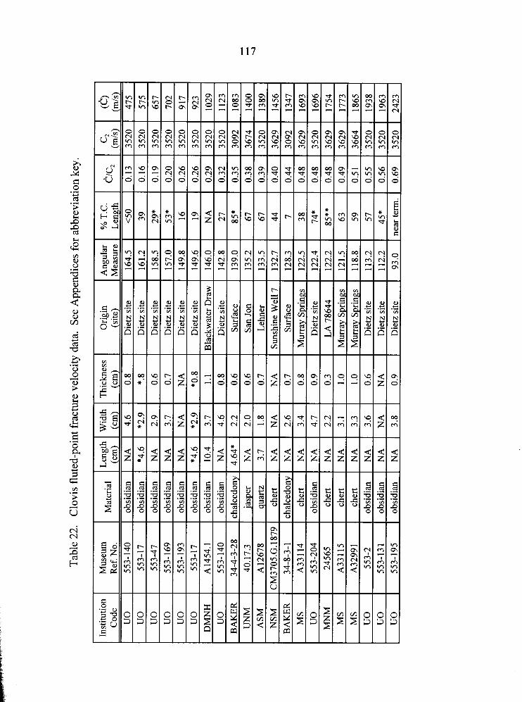
Tab
le 2
2.
Clo
vis
flut
ed-p
oint
frac
ture
vel
ocity
dat
a. S
ee A
ppen
dice
s fo
r abb
revi
atio
n ke
y.
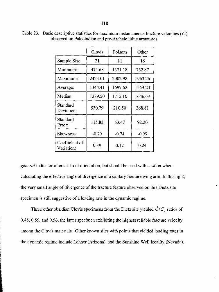
Table 23. Basic descriptive statistics for maximum instantaneous fracture velocities (c) observed on Paleoindian and pre-Archaic lithic armatures.
Standard Deviation:
11 530.79 ( 210.50 1 368.81 1
Sample Size:
Minimum:
Maximum:
Average:
Median:
Standard Error:
1 115.83 1 63.47 1 92.20 1 I Skewness: 11 -0.79 1 -0.74 ( -0.99 1
Clovis
2 1
474.68
2423.01
1344.41
1389.50
Coefficient of / 1 1 0.24 1 Variation: 0.39 0.12
general indicator of crack front orientation, but should be used with caution when
Folsom
11
1371.18
2002.98
1697.62
1712.10
calculating the effective angle of divergence of a solitary fracture wing arm. In this light,
Other
16
752.87
1963.26
1554.24
1646.63
the very small angle of divergence of the fracture feature observed on this Dietz site 1
specimen is still suggestive of a loading rate in the dynamic regime. i I
i Three other obsidian Clovis specimens from the Dietz site yielded CI C, ratios of 6 E
0.48, 0.55, and 0.56, the latter specimen exhibiting the highest reliable fracture velocity
among the Clovis materials. Other known sites with points that yielded loading rates in
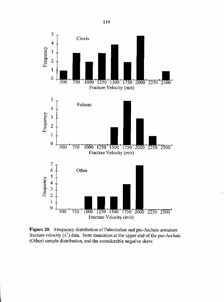
Fracture Velocity (mls)
3 -
J
Folsom 4 --
h 8 3 - - 1
g 2 -- C4
1 --
O 500 ' 750 ' 1000' 1250' 1500'
4
2 3
Fracture Velocity (mls)
Clovis --
--
I - 6 -- Other
?? --
g 4 - - 5 3 --
g 2 - - 1 --
O ' 500 ' 750 ' 1000' 1250' 1500' 1750'
0 1
g 2 -- C4
' 750 ' 1000 ' 1250 ' 1500 ' 1750 ' 2000 ' 2250 '
Fracture Velocity ( d s )
Figure 20. Frequency distribution of Paleoindian and pre-Archaic armature fracture velocity ( 6 ) data. Note truncation at the upper end of the pre-Archaic (Other) sample distribution, and the considerable negative skew.
Folsom Points
Eight Folsom fluted-points exhibited a total of 1 1 velocity-dependent fracture features
from which fracture velocity assessments were made. Types of damage observed on
points yielding fracture velocity data include tip and bending fractures. CIC, ratios
ranging from 0.38 to 0.55 were documented; notably, all of these CIC, ratios fall within
the dynamic regime, indicating high-velocity impacts (Table 24). Summary descriptive
statistics for instantaneous fracture velocity data are presented in Table 23. The
distribution of Folsom fracture velocity data is presented in Figure 20.
Most of these points were surface collected throughout Colorado and New Mexico.
One of these, collected from the Deming area of New Mexico, and exhibiting massive tip
damage, yielded a CIC, ratio of 0.55, the highest recorded for the Folsom materials. A
single specimen yielding a d l c , ratio of 0.48 was recovered from the Sunshine Well
locality (Nevada).
Other Paleoindian (or pre-Archaic) Points
Other points, variously defined as Paleoindian or pre-Archaic (cf., Willig 1989: 13-
14), from which fracture velocity data was recovered include 16 specimens identified as
Midland, Great Basin Stemmed, Western Pluvial Lakes Stemmed, Cougar Mountain
Stemmed, Humbolt, Sandia, and Windust. Represented sites and localities include
Manzano Cave, and Beargrass Draw in New Mexico; Hanging Rock Shelter, Massacre
Lake, Pine Creek Well, Mud Lake, Lake Parrnan, and Sunshine Well in Nevada; and the
Dietz site, and Christmas Valley in Oregon. These points yielded dlc, ratios ranging

121
from 0.21 to 0.56, 12 (75%) of which exhibited loading rates in the dynamic regime
(Table 25). Summary descriptive statistics for instantaneous fracture velocity data are
presented in Table 23. The distribution of these fracture velocity data is presented in
Figure 20.
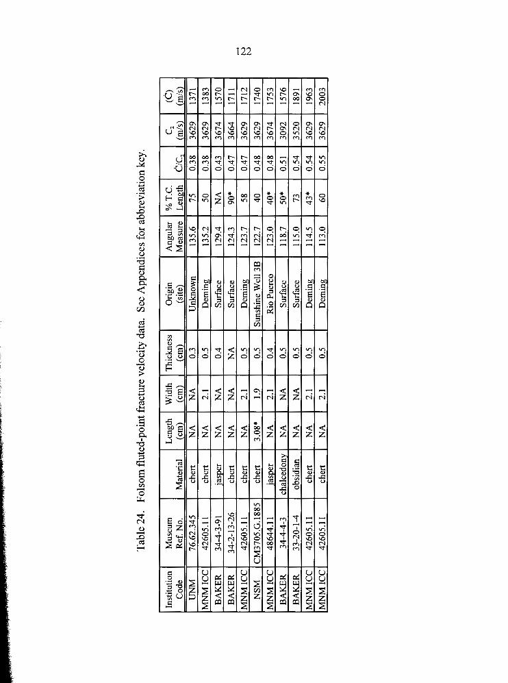
Tab
le 2
4.
Fols
om f
lute
d-po
int f
ract
ure
velo
city
dat
a. S
ee A
ppen
dice
s fo
r abb
revi
atio
n ke
y.
CI
h,
h,
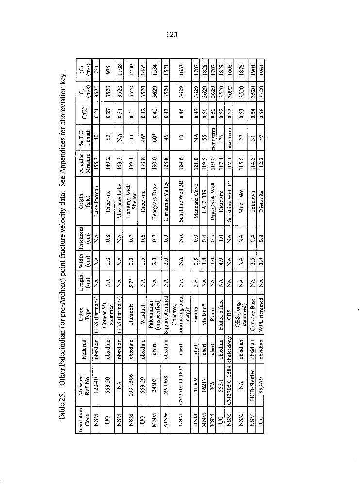
Tab
le 2
5.
Oth
er P
aleo
indi
an (o
r pre
-Arc
haic
) poi
nt f
ract
ure
velo
city
dat
a. S
ee A
ppen
dice
s fo
r abb
revi
atio
n ke
y.
l~ns
titu
tion
1 M
useu
m
Ref
. No.
120-
40
I N
SM
1 10
3-35
86
UN
M
I 41
.6.9
M
NM
I
1621
7
Lith
ic
Len
gth
Wid
th
Thi
ckne
s:
(cm
) (c
m)
(cm
) ob
sidi
an
GB
S (P
arm
an?)
N
A
NA
N
A
obsi
dian
C
ouga
rMt.
N
A
2.0
stem
med
0.
8
obsi
dian
IG
BS
(Par
man
?) 1
NA
I
NA
I
NA
I
I I
I ob
sidi
an
Hum
bolt
5.7*
2.
0 0.
7
obsi
dian
W
indu
st
NA
2.
5 0.
6
cher
t Pa
leoi
ndia
n N
A
2.3
(uns
peci
fied
) 0.
7
obsi
dian
G
BS
(lon
g N
A
NA
N
A
stem
med
)
obsi
dian
C
onca
ve B
ase
NA
2.
5 0.
4 ob
sidi
an
WPL
ste
mm
ed
NA
3.
4 0.
8
Ori
gin
(sit
e)
Lak
e Pa
rman
Die
tz s
ite
Mas
sacr
e L
ake
Han
ging
Roc
k Sh
elte
r
Die
tz s
ite
Bea
rgra
ss D
raw
Chr
istm
as V
alle
y
Suns
hine
Wel
l 3B
Man
zano
Cav
e
LA
713
39
Pine
Cre
ek W
ell
Die
tz s
ite
Suns
hine
Wel
l P2
Mud
Lak
e
unkn
own
Die
tz s
ite
Ang
ular
M
easu
re
155.
3
% T
.C.
Len
gth
40
ClC
2
0.21
c2
(mls
) 35
20
(c)
(mls
) 75
3
Fluting Data
In addition to damaged distal tips, some channel-flake scars, and channel-flakes
! themselves, were also examined in an effort to document the reduction technology b
! 6 associated with Paleoindian fluting. The fluting of bifacial points is an unusual technique k
practiced for a relatively short period of time, and, seemingly, restricted in geographical
distribution to the New World. The recent report by King and Slobodin (1996) of a
"fluted-point", approximately 4.6 cm in length, from the Uptar site in Magadan Oblast,
northeastern Siberia, does not offer convincing evidence of a fluted-point-bearing,
Paleoindian presence in Northeast Asia. While amazingly symmetrical, the single
longitudinal flake scar exhibited by this point appears instead to be a large tip fracture.
The jagged "base" does not resemble the initiation point of a channel-flake scar, nor does
it appear to have been retouched or finished in any way. In addition, the high-relief
undulations, while not completely unknown on channel-flake scars, are not characteristic.
Please note that this assessment is based solely on published photographs (King and
Slobodin 1996; Menon 1997) of the specimen, and that any conclusions should be based
on examination of the point itself.
Lacking any obvious Old World predecessors, it has been suggested (e.g., Haynes
1980) that fluting was a New World development originating somewhere between
Beringia and the southern limits of the ice-sheets, spreading south into the Plains and
Great Basin. Alternatively, if fluted points in Alaska are post-Clovis in age, then they
125
represent an influx from the south, and perhaps an origin south of the ice-sheets (Dixon
1975).
Carlson (1991) has hypothesized that logical ancestors of the Clovis fluted-point are
the bone or antler points with multiple side-hafted blade segments found in Upper
Paleolithic and Neolithic sites in Siberia, and that fluting itself is a logical development of
blade technology. Some Clovis assemblages do exhibit blade technology, and while
Carlson may be correct, I do not agree that blade and channel-flake removal are
necessarily conceptually similar (Carlson 199 1 : 84). The overall flaking technology
exhibited by classic Clovis demonstrates a high degree of platform preparation and
control in the production of broad, thin, invasive flakes, and is itself sufficient to supply
the necessary concepts and skills for channel-flake removal.
The most easily damaged component of a slotted haft and lithic armature
arrangement is usually the slot component itself. I believe fluting to be an attempt to
compensate for the relative fragility of the organic haft component by reducing the
thickness of the point base in favor of more substantial haft material on each side of the
hafting slot. There may be three reasons why this became a problem: (1) a lack of plant
materials from which to quickly and easily fashion replacement hafts, and a reliance
instead on more expensive bone and antler hafting material (i.e., it was less expensive to
replace the lithic component than the haft component). This could be due to a shift to a
tundra type of environment where plant materials for haft construction were scarce; (2) it
may have been an effort to increase the maintainability (Bleed 1986) of the weapon by i
designing the lithic component to fail before the haft component. For mobile hunters, it
126
would be easier to carry replacement points than replacement hafts; or (3) a recent
technological shift from a hafting arrangement in which the extant point design was
sufficiently thin (relatively speaking) at the base, to one in which it was suddenly
inadequate. Such a shift may have been from thick-shafted spears, to much smaller
diameter spearthrower darts. Stemming may have been an alternative solution to the
same problem.
Most of the research concerning fluting technology itself has centered around the
more aesthetically-appealing Folsom points, and is related to the techniques of channel-
flake removal (e.g., Akerman and Fagan 1986; Boldurian, Fitzgibbons, and Shelley 1985;
Boldurian et al. 1986, 1987; Callahan 1979a, 1979b; Crabtree 1966; Flenniken 1978;
Frison and Bradley 1980, 198 1 ; Gryba 1988; Ibarra and Wellman 1988; Imel 1988; Neil1
1952; Patten 1979a, 1979b, 1980; Sollberger 1977, 1985; Sollberger and Patterson 1980,
1986). Crabtree (1 966:22), having experimented with several different fluting
techniques, concluded that indirect percussion with a rest, or pressure with clamps and
anvil were the two techniques most likely employed in fluting the Lindenmeier Folsom.
Researchers have also proposed that leverage machines may have been used to pressure-
flute Paleoindian points (e.g., Frison and Bradley 198 1 ; Ibarra and Wellman 1988;
Sollberger and Patterson 1980). In fact, practically every known reduction technology
(i.e., pressure flaking, indirect- and direct-percussion flaking) can be demonstrated to
produce adequate channel-flakes. In replicating points for this, and other research, I have
found both indirect and direct percussion to be simple and effective techniques for
fluting. Due to the fact that different reduction techniques work, and often produce
127
morphologically similar results, no one method has ever been demonstrated to be the sole
technique used by Paleoindian knappers.
The utility of fracture velocity data to impart information about manufacturing or
reduction techniques was noted in Chapter IV. An example of the practical application of
this type of data collection involves the recording and interpretation of fracture velocity
relevant micro-features observed on the channel-flake scars of Paleoindian fluted points.
During this research, fracture velocity data were collected from the channel-flake scars of
12 obsidian Clovis points (Table 26). CIC, ratios recorded for these specimens range
from 0.02 to 0.18.
Of particular interest are the very low fracture velocities obtained from the channel-
flake scars of certain points, notably those recovered from the Dietz site (Oregon), Lake
Tonopah (Nevada), and Blackwater Draw (New Mexico). The CIC, ratios for these
specimens range from 0.02 to 0.18, but fully 75% (nine of twelve) lie between 0.02 and
0.09, indicating quasi-static loading rates which correspond to pressure flaking.
One such specimen is an incomplete obsidian Clovis point from the Lake Tonopah
Locality, that was broken during fluting of the second face. The CIC, ratio for a single
fracture wing observed on the channel-flake scar which broke the point is 0.04. Based on
a C, value of 3520 d s for Modoc obsidian, the fracture velocity of 144 d s indicates that
pressure flaking, using either hand or chest-crutch methods, was employed for fluting
(refer to Table 3).
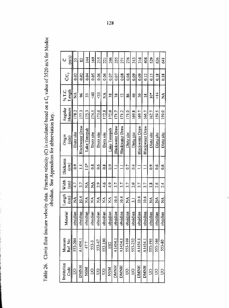
Tab
le 2
6.
Clo
vis
flut
e fr
actu
re v
eloc
ity d
ata.
Fra
ctur
e ve
loci
ty (
c) i
s ca
lcul
ated
bas
ed o
n a
C, v
alue
of
3520
m/s
for
Mod
oc
obsi
dian
. Se
e A
ppen
dice
s for
abb
revi
atio
n ke
y.
The same technology is in evidence on other points from the Dietz Site and
Blackwater Draw. The Blackwater Draw specimen (Denver Museum of Natural History
reference number Al454. I), is a relatively large obsidian Clovis point. Although fluted
on both faces, pertinent micro-fracture features were observed only on the larger channel-
flake scar. Approximately 50 mm in length, this channel-flake scar exhibits at least five
fracture wing sites which indicate an average fracture velocity for the fluting process of
266 m/s (see also Figure 8). Instantaneous fracture velocities for this specimen range
from 82 m/s to 408 m/s, based on a C, value of 3520 m/s for Modoc obsidian. As stated
in Chapter IV, however, only those instantaneous velocities lying between 20% and 50%
of the terminal crack length offer an accurate reflection of the fracture velocity. The
channel-flute fracture velocity is therefore reflected by two fracture wing sites lying at
30% and 38% of the terminal crack length. ~ h e d l c , ratios derived from these features
are 0.09 and 0.07 respectively, and again suggest that a pressure flaking method was
employed to remove this large channel-flake.
One point which deserves particular attention is a very large Clovis mid-section
fragment from the Dietz site (Oregon State Museum of Anthropology reference number
553-204). The CIC, ratio for the single fracture wing observed on one of its channel-
flake scars is 0.02. Based on a C, value of 3520 mls for Modoc obsidian, this very low
value indicates a fracture velocity of 55 m/s (the actual CIC, value is 0.0157 if
considered to four decimal places). Considering the size of the channel-flake indicated by
this point fragment, along with the experimental evidence from Chapter IV, and the data
130
collected from chest-punched blades produced by Donald Crabtree (see page 5 I), it
appears that this point was fluted using a chest-punch, or other similar pressure flaking
device, which permitted a very slow application of a large amount of pressure. To my
knowledge, this is the first empirical confirmation of a specific Paleoindian fluting
technology.
Summary
Loading rates in the dynamic regime were documented on 27 Paleoindian fluted-
points, and 16 other points variously defined as Paleoindian or pre-Archaic (cf., Willig
1989: 13-14). Previous experimentation failed to generate dynamic fractures during any
known lithic reduction process, or from accidental abuse. Loading rates in the dynamic
regime were only generated through high-velocity impacts, of the type associated with
mechanical propulsion devices such as the spearthrower and bow. Assuming that
Paleoindian peoples did not possess bow and arrow technology, the data therefore
indicate that they employed the spearthrower, and thus constitutes the earliest direct
evidence for this weapon's use in the New World. While the presence of the
spearthrower is indicated, this does not imply that Paleoindians did not employ other
types of weapons. Experiments indicate that the lower range of loading rates documented
for Paleoindian points overlaps the upper range of loading rates associated with both
javelins and spears. Even though the Paleoindian data fall within the range of variation
documented for the experimental darts, and higher, one cannot rule out the possibility that
all three types of weapons may have been in use.
131
In addition to data from use-related fractures, a small body of data was generated
through the examination of channel-flake scars from several obsidian Clovis points,
revealing that these artifacts were often pressure fluted, probably through the use of a
chest- or crutch-type pressure tool (a secondary function for organic points?).
My own experience, and probably that of many other flintknappers as well, suggests
that large, effective channel-flakes can be removed using a variety of reduction
techniques. Large channel-flake scars exhibiting very low fracture velocities, like those
observed during this study, suggest that at least some obsidian points were fluted as a co-
operative effort, since it probably required at least two individuals to simultaneously hold
a preform and operate a chest-punch unless some kind of clamp or jig was employed to
secure the preform. A possible alternative might be a mechanical pressure-flaking device
like that proposed by Frison and Bradley (1981).
CHAPTER VII
CONCLUSIONS
"Science is nothing but developed perception, integrated intent, common sense rounded out and minutely articulated."
- George Santayana -
"People who like this sort of thing will find this the sort of thing they like." - Book review by Abraham Lincoln -
The interpretation of archaeological data relies to a great extent on the use of
analogy. The ability of these data to accurately reflect prehistoric events depends
essentially on the integrity of the analogue employed. Traditional analyses of weapon
armature technologies (e.g., Corliss 1972; Evans 1957; Forbis 1962; Thomas 1978; Shott
1997; Wyckoff 1964 ) employ classification schemes to identifl projectile points as either
spear, dart, javelin, or arrow armatures. For example, the identification of an arrow
armature is traditionally a two-step process: (1) the investigator recognizes an artifact as a
"projectile point", and (2), classifies it as an arrow point based on certain pre-defined
criteria that distinguish it from other classes of projectile points. The basic logical fallacy
of such schemes is the assumption that the investigator knows, apriori, that the artifact in
question served as a projectile armature (cf., Ahler 1971).
In this case, the inadequacy of the traditional classification method for identification
of projectile armatures lies at the very heart of its theoretical foundation within the direct
historic approach. Our knowledge of what constitutes a "projectile point" is derived from
133
example, is defined as an artifact which has been observed attached to an arrow shaft.
Similarly, classification schemes like that proposed by Thomas (1978) and Shott (1997)
define criteria for classes based on data derived from artifacts assumed to be
representative of those classes. Consequently, such models are untestable because
relevant data have already been used in their construction.
From a theoretical (i.e., scientific or logical) standpoint, as long as our models are
derived from data, we have no objective criteria with which to evaluate them. As Kosso
(1 989:246) has stated, objective evidence is ". . . evidence that is verified independently
of what it is evidence for." Therefore, instead of deriving our models from our data,
models should be constructed from relations among phenomena that are predicted from
theory and tested against data (Rigaud and Simek 1987:48). The methodology employed
in this research to determine precursory loading rates is free of data-based interpretive
analogy (while it is true that bifacial points were selected for study, based on general,
normative, morphological variables that suggest suitability as armatures, no assumptions
were made with regard to artifact function. Instead, function was identified through
analysis of fracture velocity. Had this study failed to document dynamic lithic fracture
velocities among Clovis fluted points it would merely have suggested that these artifacts
were not used as high-speed projectile armatures, and would not necessarily indicate that
Clovis did not employ the spearthrower in connection with some, as yet unknown, type of
armature). Instead, it is a non-subjective, quantitative method firmly rooted in the
physical sciences. The physical processes that created the velocity-dependent fracture
features during the late-Pleistocene are the same physical processes that we observe
134
today. The effects of 13,000 year-old actions were, in a very real way, set in stone,
providing a Pompeii-like opportunity to measure the loading rates generated by an
ancient weapon system.
The dynamic loading rates associated with the Paleoindian points examined during
the course of this investigation, offer conclusive evidence for the use of the spearthrower
during the earliest, well documented, period of human prehistory in the New World. The
significance of this discovery addresses our basic understanding of Paleoindian peoples
and life-ways. The unprecedented appearance of "technology oriented" hunter-gatherers
(Kelly and Todd 1988) at the close of the Pleistocene, marks one of the more dramatic
periods in hunter-gatherer prehistory. Their fully-developed biface technology, coupled
with a logistic pattern of extreme mobility, offered a highly effective solution to the risks
of exploiting unknown and rapidly changing environments. It is tempting to hypothesize
that Paleoindian cultural and technological advances may be the result of the right
technology combined with the right place and time.
The Upper Paleolithic cultures of the Central Russian Plain are known from sites
such as Mezhirich, Mezin, and Yudinovo, for their use of enormous quantities of
mammoth bone to construct elaborate and complex dwellings. According to Soffer
(1 985), current evidence suggests that the majority of the bone used in these structures
was collected from the treeless tundra, rather than through active hunting, but that
mammoth hunting was indeed practiced.
The distribution of Kostenki knives and points suggests a general west to east
movement of Upper Paleolithic technology which parallels the megafauna extinction
trajectory posited by Martin (1 982). While this trend appears to begin prior to the Valdai
maximum, which occurred between approximately 20,000 and 18,000 B.P. and saw the
absence of human occupation on the Central Russian Plain (Ivanova 1977, cited in Soffer
1985; Levkovskaya 1977 cited in Soffer 1985; Soffer 1985: 173-1 76; Klein 1969), Soffer
(1985, 1987) has suggested that localized environmental deterioration may have been felt
earlier by groups living in Eastern Europe between the Scandinavian ice sheet and Alpine
glaciers. It is tempting to hypothesize that these already highly-mobile hunters and
gatherers may have been prompted to move eastward into areas of lower population
density, eventually spreading into Beringia sometime after 18,000 B.P. (see also Haynes
In Upper Paleolithic Western Europe, the spearthrower had been in use since at least
the Magdalenian approximately 17,000 years ago, and perhaps much earlier (cf., Caton-
Thompson 1946; Cressman and Krieger 1 94O:3 6; Knecht 1994; Krause 1905: 124;
Massey 1961:81). Indeed, Dickson (1985:6) has speculated that it may have been in use
as early as 80,000 years ago during the Mousterian. There is currently no empirical
evidence for its use among the Upper Paleolithic peoples of the Central Russian Plain, but
if future research reveals they had possessed the weapon, they may be considered as
possible progenitors of New World Paleoindians.
Many of the Late Paleolithic mammoth-hunter sites of Eurasia show similarities in artifacts and features such as dwellings, fireplaces, and ocher burials. While game takes were not exclusively mammoths, the socioeconomic orientation of the cultures toward the hunting and utilization of mammoth meat, hide, bones, and ivory is clearly manifest. The mammoth was to the Paleolithic hunter as the reindeer is to the Laplander or the inland Eskimo. On the basis of the similarities among Clovis stone and bone artifact assemblages and such Late Paleolithic
hunting camps as Pavlov, Dolni Vestonice, level 5 of Kostienki I [sic], and many others, I assume that the earliest root for Clovis stems from Europe during the early Late Paleolithic (Gravettian-Aurignacian), about 28,000 years ago. Mammoth hunters moving eastward gave rise to such sites as Afontova Gora 11, Mal'ta and Buret I sometime between 25,000 and 15,000 BP. During this time cultural diversity had already developed in eastern Siberia, where Dyuktai people had acquired a core-and-blade technology. Bifacial points or knives at Dyuktai Cave and bone points slotted for microblades at Afontova Gora may be evidence of cultural mixing, but some people apparently did not adopt microblades. It may be these Mal'ta-Afontova Gora descendants that entered Beringia with artifacts characterized by bifaces, blades, and cylindrical bone and ivory points between 20,000 and 15,000 years ago [Haynes 1982:396-3971.
Far-reaching hypotheses aside, early Paleoindians faced unknown and rapidly
changing, high-risk environments with a very reliable (Bleed 1986) form of weaponry.
The spearthrower provided a method of delivering relatively heavy projectiles at very
high velocities, up to 50 and 60 meters per second. These velocities compare favorably
with the bow, but due to the mass of the dart, result in much greater impact force.
. . . we have computed kinetic energies from average throws in excess of 350 Joules. This is four times the kinetic energy carried by a modern arrow fired from an efficient, modern compound bow; the AM0 standard is a 540 grain (35 g) arrow fired from a 30-inch draw, 60 pound peak-weight bow. Modern equipment meeting these standards will produce projectile velocities up to 70 d s , resulting in kinetic energies less than 86 Joules. Traditional bows would be considerably less efficient. Raymond (1986:Table 5) calculates a kinetic energy of 12.6 Joules for Ishi's bow based on a velocity of 30 d s using a 28 g arrow [Hutchings and Briichert 19971.
When combined to create a projectile with effective penetration, this combination of
large mass and high velocity results in an extremely efficient weapon. For example, in
his account of the De Soto expedition to the southeastern United States in the 16th
century, Garcilaso de la Vega noted that the spearthrower propelled darts "with extreme
force, so that it has been known to pass through a man armed with a coat of mail"
(Swanton 1938:358). Comparing the spearthrower to the javelin, data from the
137
experiments discussed in Chapter V indicate that the spearthrower can propel a dart with
as much as 185% of the velocity of its hand-thrown equivalent.
An additional advantage of the spearthrower is that it permits hunters to maintain a
safer distance from aggressive prey than does the spear or javelin, thereby increasing
hunting success by reducing risk of personal injury. In essence, the spearthrower,
equipped with a relatively heavy dart, is the prehistoric equivalent of the modern elephant
gun.
Dynamic loading rates, indicating high-velocity fractures, were indicated not only
on Clovis and Folsom fluted points, but on other early point types including Plano,
Midland, Western Pluvial Lakes Stemmed, Great Basin Stemmed, and Windust.
Importantly, this indicates that no one hafting technique was uniquely associated with
spearthrower technology during this period, and may indicate that early peoples were
experimenting with hafting methods rather than delivery technologies. This in turn
implies a recent switch from an earlier technology.
Logical precursors to these lithic armatures are of course the bone, antler, and ivory
bevel-based points common to the Upper Paleolithic, and found at several New World
Paleoindian sites and localities, including the Tenana Valley, Alaska (Rainey 1940), the
Grenfel site, Saskatchewan (Wilmeth 1968), Lind Coulee, Washington (Daugherty 1 %6),
the Richie-Roberts site, Washington (Mehringer 1989), Sheaman (Anzick) site, Wyoming
(Lahren and Bonnichsen 1974), Klamath Lake, Oregon (Cressman 1 %6), Goose Lake,
California (Riddell 1973), Blackwater Draw, New Mexico (Hester, Lundelius, and
Fryxell 1972; Sellards 1952), and several submerged deposits in Florida (see Dunbar
138
1991 ; Jenks and Simpson 194 1). Similar points were obviously considered effective
during the European Upper Paleolithic (e.g., Knecht 1994), but an experimental study by
Stodiek (1993:200-202) determined that they do not penetrate very well since they pierce
a small hole and push it open rather than slicing a suitably-sized hole like a stone point.
So while the organic points may have been sufficient for hunting smaller or younger
animals, large mammoth and bison, with their thicker hides, probably demanded a more
efficient, albeit costlier, lithic armature.
Organic points may have survived as economic alternatives, used as backups after
an initial attack using lithic armatures, or may have been maintained as killing lances to
dispatch incapacitated prey. Their beveled bases would create a relatively smooth joint
with a shaft or foreshaft, allowing them to be repeatedly withdrawn and thrust without
fear of snagging on bone or tendon. Alternatively, they may have survived simply as
economic alternatives intended for smaller, or younger game. In any case, maintenance
of bone, antler, and ivory technologies would have provided insurance against
inopportune depletion of curated lithic armatures until the group returned to a known
tool-stone quarry or located a new source.
I believe the contributions made by this research to be twofold. Most simply, it has
confirmed what many Paleoindian archaeologists have believed all along; that
Paleoindians employed spearthrower weaponry. The difference now being that we can
support this position with theory-based, objective empirical evidence, giving us a firm
foundation for higher-order analyses of Paleoindian life-ways. This research has also
139
outlined a relatively simple analytical methodology that should prove to have many useful
applications in archaeology, in both use-related and manufacture-related studies.
Although fracture velocity data may not be able to positively identify the precursory
loading rates of all artifacts suspected of being weapon armatures, the data may also be
incorporated in traditional discriminant function analyses (e.g., Thomas 1978; Shott
1997) to refine the discrimination of functional types.
The loading rate parameters employed here were generated through manufacture-
related experiments using Glass Butte obsidian. This was done for reasons of
expediency; due to the relative rarity of velocity dependent fracture features, it was
simply not advantageous to use any but the finest-grained material available for the
experimental research. Considering its high C, value of 3865 m/s, compared to
approximately 3600 to 3700 m/s for most fine-grained flint toolstones, the loading rate
boundaries outlined here may be considered high, but again, it was simply not expedient
to identify all Paleoindian artifact material sources, and perform the same range of
experiments on each. By using a material with a relatively high C, value, and thus raising
the rapidldynamic loading rate boundary, it is possible that fewer Paleoindian artifacts
have been documented with dynamic loading rates than may have been the case had
Edwards flint (C, = 3629 d s ) , for example, been used. Had the loading rate scheme
outlined by Tomenchuk (1985:Table 12.7) been used, this research would have
documented approximately 2 1 % more Paleoindian artifacts exhibiting dynamic loading
rates. Similarly, the C, value of 3520 m/s for Modoc obsidian was used for all fracture
velocity calculations involving Paleoindian obsidian artifacts, rather than the value for
140
Glass Butte obsidian, resulting in fewer dynamic loading rates being documented than
might otherwise have been the case.
While the approach followed here has adequately demonstrated that dynamic
loading rates associated with spearthrower use are often exhibited by Paleoindian
armatures, future research should compare the manufacture- and use-related loading rate
ranges associated with other tool-stone materials. I do not expect significant variation
from the results presented here, but I feel that the potential of the methodology warrants
all possible refinement.
An additional area where refinements are possible, is that of data collection.
Velocity dependent fracture surface features are often so small that they are difficult to
locate. The definition of these features is often improved by varying the angle of incident
lighting to highlight the microscopic ripples against their own shadows. Unfortunately,
many of the finest-grained lithic materials are also extremely reflective, so that when a
feature is located, it is sometimes difficult to orient the plane of the fracture perpendicular
i to the viewing axis of the microscope . Large deviations from the perpendicular will t
adversely affect angular measurements. It is possible that the use of a scanning electron
microscope might alleviate some aspects of this potential problem, while the application
of digitizing and CAD systems may improve the accuracy of data recovery.
REFERENCES CITED
Ahler, Stanley 1971 Projectile Point Form and Function at Rodgers Shelter, Missouri. Missouri
Archaeological Society Research Series No. 8.
Ahler, Stanley A., and R.B. McMillan 1975 Material Culture at Rodgers Shelter: A reflection of Past Human Activities.
In Prehistoric Man and his Environments: A Case Study in the Ozark Highland, edited by W.R. Wood and R.B. McMillan, pp. 163- 199. Academic Press, Inc., New York.
Akerman, Kim, and John L. Fagan 1986 Fluting the Lindenrneier Folsom: A Simple and Economical Solution to the
Problem, and its Implications for Other Fluted Point Technologies. Lithic Technology l5(l): 1-8.
Amick, Daniel S. 1996 Regional Patterns of Folsom Mobility and Land Use in the American
Southwest. World Archaeology 27(3):4 1 1-426.
Baker, W.E., and A.V. Kidder 1937 A Spear Thrower from Oklahoma. American Antiquity 3(l):5 1-52.
Barton, R.N.E., and C.A. Bergman 1982 Hunters at Hengistbury: Some Evidence from Experimental Archaeology
World Archaeology 14(2):237-248.
Bateson, H. Marshall 195 1 Some Views on the Breaking of Glass Derived from the Examination of
Fracture Surfaces. Journal of the Society of Glass Technology 25: 108-1 18.
Becker, Lou 1993 Hunting with the Atlatl. Traditional Bowhunter 5(2):40-44.
Bergman, C.A., E. McEwen, and R. Miller 1988 Experimental Archery: Projectile Velocities and Comparison of Bow
Performances. Antiquity 62:658-670.
Bergman, C.A., and M.H. Newcomer 1983 Flint Arrowhead Breakage: Examples from Ksar Akil, Lebanon. Journal of
Field Archaeology 10% 8-243.
Berry, Michael S. 1976 Remnant Cave. In Swallow Shelter and Associated Sites, edited by Gardiner
F. Dalley, pp. 1 15-127. University of Utah Anthropological Papers, no. 96. University of Utah Press, Salt Lake City.
Bieniawski, Z.T. 1968 The Phenomenon of Terminal Fracture Velocity in Rock. Rock Mechanics
and Engineering Geology 6: 1 13-125.
Binford, Lewis Roberts 1979 Organization and Formation Processes: Looking at Curated Technologies.
Journal of Anthropological Research 3 5(3):255-273.
Birch, Francis, J.F. Schairer, and H. Cecil Spicer 1942 Handbook of Physical Constants. Geological Society of America, Special
Paper 36.
Blair, B.E. 1955 Physical Properties of Mine Rock, Part 111. United States Department of the
Interior, Bureau of Mines, Report of Investigations, 5 130.
I t Bleed, Peter 1 1986 The Optimal Design of Hunting Weapons: Maintainability or Reliability.
American Antiquity 5 1 (4):737-747. B i,
Blitz, Jack 1967 Fundamentals of Ultrasonics. Second edition. Buttenvorths, London.
Boldurian, Anthony T. 1990 Lithic Technology at the Mitchell Locality of Blackwater Draw: A Stratified
Folsom Site in Eastern New Mexico. Plains Anthropologist 35-130, Memoir
Boldurian, Anthony T., George Agogino, Phillip H. Shelley, and J. Mark Slaughter 1987 Folsom Biface Manufacture, Retooling, and Site Function at the Mitchell
Locality of Blackwater Draw. Plains Anthropologist 32(117):299-3 1 1.
Boldurian, Anthony T., Philip T. Fitzgibbons , and Phillip H. Shelley 1985 Fluting Devices in the Folsom Tradition: Patterning in Debitage Formation
and Projectile Point Basal Configuration. Plains Anthropologist 30(110 pt. l):293-303.
Boldurian, Anthony T., Philip T. Fitzgibbons , Phillip H. Shelley, and John L. Montgomery
1986 A Reply to Sollberger and Patterson on Experimental Folsom Biface Manufacture. Plains Anthropologist 3 1(113):245-248.
Bonnichsen, Robson, and David Young 1980 Early Technological Repertoires: Stones to Bones. Canadian Journal of
Anthropology 1 : 123-228.
Bradley, Bruce A. 1982 Flaked Stone Technology and Typology. In The Agate Basin Site : A Record
of the Paleoindian Occupation of the Northwestern High Plains, edited by George C. Frison and Dennis J. Stanford, pp. 18 1-203. Academic Press, New York.
1993 Paleo-Indian Flaked Stone Technology in the North American High Plains. In From Kostenki to Clovis: Upper Paleolithic - Paleo-Indian Adaptations, edited by Olga Soffer and N.D. Praslov, pp.251-262. Plenum Press, New Y ork.
Browne, Jim 1940 Projectile Points. American Antiquity 5 :209-2 13.
i Butler, William B. F
i 1975 The Atlatl: The Physics of Function and Performance. Plains Anthropologist 20(68):105-110. t
Callahan, Errett 1979a Comments on Patten's Analysis of the Clovis from Clovis. Flinthapper's
Exchange 2(3): 17.
1979b The Basics of Biface Knapping in the Eastern Fluted Point Tradition; A Manual for Flint-knappers and Lithic Analysts. Archaeology of Eastern North America 7(l): 1-1 80.
Campbell, E. W.C., and W.H. Campbell 1940 A Folsom Complex in the Great Basin. Masterkey 14:7-11.
Carlson, Roy L. 1991 Clovis from the Perspective of the Ice-Free Corridor. In Clovis: Origins and
Adaptations, edited by Robson Bonnichsen and Karen L. Turnmire, pp.8 1-90. Center for the Study of the First Americans, Oregon State University, Corvallis.
Carrere, P., and S. Lepetz 1988 Etude de la Dynamique des Pointes de Projectiles: Elaboration d'une
Methode. Memoire de Maitrise. Universite de Paris I.
Caton-Thompson, G. 1946 The Aterian Industry: Its Place and Significance in the Paleolithic World.
Journal of the Royal Anthropological Institute of Great Britain and Ireland 76:87-130.
Clausen, Carl J., H.K. Brooks, and A1 B. Wesolowsky 1975 The Early Man Site at Warm Mineral Springs, Florida. Journal of Field
Archaeology 2(3): 19 1-2 13.
Cockrell, W.A., and L. Murphy 1978 Pleistocene Man in Florida, Archaeology of Eastern North America 6: 1 - 13.
Collins, M.D., G.L. Evans, T.N. Campbell, M.C. Winans, and C.E. Mear 1989 Clovis Occupation at Kincade Shelter, Texas. Current Research in the
Pleistocene 6:3-5.
Congleton, J., and N.J. Petch 1967 Crack Branching. Philosophical Magazine 8(16):749-760.
Corliss, David W. 1972 Neck Width of Projectile Points: An Index of Culture Continuity and Change.
Occasional Papers of the Idaho State University Museum, No. 29. Pocatello, Idaho.
Cosgrove, C.B. 1947 Caves of the Upper Gila and Hueco Areas in New Mexico and Texas. Papers
of the Peabody Museum of American Archaeology and Ethnology, vo1.24, no.2, Cambridge.
Cotterell, Brian, and Johan Kamminga 1979 The Mechanics of Flaking. In Lithic Use- Wear Analysis, edited by Brian
Hayden, pp.97-112. Academic Press, New York.
1987 The Formation of Flakes. American Antiquity 52(4):675-708.
1990 Mechanics of Pre-industrial Technology : An Introduction to the Mechanics ofAncient and Traditional Material Culture. Cambridge University Press, Cambridge.
Crabtree, Don E. 1966 A Stoneworker's Approach to Analyzing and Replicating the Lindenmeier
Folsom. Tebiwa 9:3-39.
1968 Mesoamerican Polyhedral Cores and Prismatic Blades. American Antiquity 33(4):446-478.
1975 Comments on Lithic Technology and Experimental Archaeology. In Lithic Technology, edited by Earl Swanson, pp. 105- 1 14. Mouton Publishers, The Hague, Paris.
Cressman, L.S. 1944 New Information on South-Central Oregon Atlatls. The Masterkey
18(6): 169-1 79.
1956 Klamath Prehistory: The Prehistory of the Culture of the Klamath Lake Area, Oregon. Transactions of the American Philosophical Society, Vol. 46, Part 4. Philadelphia.
1977 Prehistory of the Far West. University of Utah Press, Salt Lake City.
Cressman, L.S., and Alex D. Krieger 1940 Atlatls and Associated Artifacts from Southcentral Oregon. In Early Man in
Oregon: Archaeological Studies in the Northern Great Basin, edited by L.S. Cressman, Howell Williams, and Alex D. Krieger, pp. 16-52. University of Oregon Monographs, Studies in Anthropology No.3, University of Oregon, Eugene.
Cundy, B.J. 1989 Formal Variation in Australian Spear and Spearthrower Technology. BAR
International Series no. 546. (B.A.R.), Oxford.
Curran, Mary Lou 1984 The Whipple Site and Paleoindian Tool Assemblage Variation: A
Comparison of Intrasite Structuring. Archaeology of Eastern North America 12:5-40.
Dalley, Gardiner F. 1970 Artifacts of Wood. In Hogup Cave, edited by Melvin C. Aikens, pp.153-186.
University of Utah Anthropological Papers, No. 93. University of Utah Press, Salt Lake City.
1976 Swallow Shelter and Associated Sites. University of Utah Anthropological Papers, no. 96. University of Utah Press, Salt Lake City.
Dalley, G.F., and K.L. Petersen 1 970 Additional Artifacts from Hogup Cave. Appendix X. In Hogup Cave, edited
by Melvin C. Aikens, pp.283-286. Univ. of Utah Anthropological Papers, No. 93.
Daugherty, R.D. 1956 Archaeology of the Lind Coulee Site, Washington. Proceedings of the
American Philosophical Society, Vol. 100, No. 3, pp.223-278. Philadelphia.
Dawson, J., and W. J. Judge 1969 Paleo-indian Sites and Topography in the Middle Rio Grande Valley of New
Mexico. Plains Anthropologist 14: 149- 163.
Dickson, D.B. 1985 The Atlatl Assesed: A Review of Recent Anthropological Approaches to
Prehistoric North American Weaponry. Bulletin of the Texas Archaeological Society 56:l-38.
Dixon, E. James Jr. 1975 The Gallagher Flint Station, an Early Man Site on the North Slope, Arctic
Alaska, and its Role in Relation to the Bering Land Bridge. Arctic Anthropology 12:68-75.
Dunbar, James S. 1991 Resource Orientation of Clovis and Suwannee Age Paleoindian Sites in
Florida. In Clovis: Origins and Adaptations, edited by Robson Bonnichsen and Karen L. Turnmire, pp. 185-21 3. Center for the Study of the First Americans, Oregon State University, Corvallis.
Eder, Stephen (producer) 1988 The Search for Ancient Americans (VHS). Vestron Video, Van Nuys, CA.
Evans, Oren F. 1957 Probable Use of Stone Projectile Points. American Antiquity 23(1):83-84.
,
Fagan, Brian M. 1987 The Great Journey: The Peopling of Ancient America. Tharnes and Hudson
Ltd., London.
Falkenberg, A.J. 1968 Spyd og Kastetr~r fra Murinbataene I Nord-Australia. University of Oslo
Museum of Ethnography Annual, 1 5-38.
Faulkner, Alaric 1972 Mechanical Principles of Flintworking. Unpublished Ph.D. dissertation,
Department of Anthropology, Washington State University, Pullman.
Fenenga, Franklin 1953 The Weights of Chipped Stone Points: A Clue to Their Functions.
Southwestern Journal of Anthropology 9:309-323.
Fenenga, Franklin, and Robert F. Heizer 194 1 The Origins and Authenticity of an Atlatl and Atlatl Dart from Lassen
County, California. American Antiquity 7(2): 134- 146.
Ferring, C.R. 1990 The 1989 Investigations at the Aubrey Clovis Site, Texas. Current Research
in the Pleistocene 7: 10- 12.
Field, J.E. 197 1 Brittle Fracture: Its Study and Application. Contemporary Physics 12(1): 1 -
31.
Figgens, J.D. 1927 The Antiquity of Man in America. Natural History 27:229-239.
1933 A Further Contribution to the Antiquity of Man in America. Proceedings of the Colorado Museum of Natural History 12(2).
Fischer, Anders, Peter Vemrning Hansen, and Peter Rasmussen 1984 Macro and Micro Wear Traces on Lithic Projectile Points: Experimental
Results and Prehistoric Examples. Journal of Danish Archaeology 3: 19-46.
Flenniken, J. Jeffrey 1978 Reevaluation of the Lindenmeier Folsom: A Replication Experiment in Lithic
Technology. American Antiquity 43(3):473-.
198 1 Replicative Systems Analysis: A Model Applied to the Vein Quartz Artifacts @om the Hoko River Site. Washington State University Laboratory of Anthropology Reports of Investigations, No. 59. Washington State University, Pullman.
Fonseca, J.G., J.D. Eshelby, and C. Atkinson 1971 The Fracture Mechanics of Flint-Knapping and Allied Processes.
International Journal of Fracture Mechanics 7(4):42 1-433.
Forbis, Richard G. 1962 The Old Woman's Buffalo Jump, Alberta. Contributions to Anthropology,
National Museum of Canada, Bulletin No. 180. Department of Northern Affairs and National Resources, Ottawa.
Frison, George C. cultural Activity Associated with Prehistoric Mammoth Butchering and Activity. Science 1 94:728-730.
Prehistoric Hunters of the High Plains. Academic Press, New York.
The CarterKerr-McGee Paleoindian Site: Cultural Resource Management and Archaeological Research. American Antiquity 49(2):288-3 14.
Experimental Use of Clovis Weaponry and Tools on African Elephants. American Antiquity 54(4):766-784.
Prehistoric Hunters of the High Plains, Second Edition. Academic Press, New York.
North American High Plains Paleo-Indian Hunting Strategies and Weaponry Assemblages. In From Kostenki to Clovis: Upper Paleolithic - Paleo-Indian Adaptations, edited by Olga Soffer and N.D. Praslov, pp.237-249. Plenum Press, New York.
Frison, George C., and Bruce A. Bradley 1980 Folsom tools and technology at the Hanson site, Wyoming. University of
New Mexico Press, Albuquerque.
i L 198 1 Fluting Folsom Projectile Points: Archaeological Evidence. Lithic
Technology 1 O(1): 13-2 1.
Frison, George C., and Carolyn Craig 1982 Bone, Antler, and Ivory Artifacts and Manufacture Technology. In The
Agate Basin Site : A Record of the Paleoindian Occupation of the Northwestern High Plains, edited by George C. Frison and Dennis J. Stanford, pp. 157-1 73. Academic Press, New York.
Frison, George C., and Dennis J. Stanford (editors) 1982 The Agate Basin Site : A Record of the Paleoindian Occupation of the
Northwestern High Plains. Academic Press, New York.
Frison, George C., and Lawrence C. Todd 1986 The Colby Mammoth Site: Taphonomy and Archaeology of a Clovis Kill in
Northern Wyoming. University of New Mexico Press, Albuquerque.
Frison, George.C., M. Wilson, and D.J. Wilson 1976 Fossil Bison and Artifacts from an Early Altithermal Period Arroyo Trap in
Wyoming. American Antiquity 41 :28-57.
Frison, George C., and George M. Zeimens 1980 Bone Projectile Points: An Addition to the Folsom Cultural Complex.
American Antiquity 45(2):23 1-237.
Funk, R.E., T.P Weinman, and P.L. Weinman 1969 The Kings Road Site: A Recently Discovered Paleo-Indian Manifestation in
Greene County, New York. New York State Archeological Association Bulletin 45 : 1-23.
Gilliland, Marion Spjut 1975 The Material Culture of Key Marco Florida. The University Presses of
Florida. Gainesville.
Goldberg, Norman, and Michele A. Frank 1983 Lab Report: Contax RTS 11. Popular Photography 90(2):66-69.
Goodman, Mary Ellen 1944 The Physical Properties of Stone Tool Materials. American Antiquity
9(4):415-433.
Graham, R.W. 1979 Paleoclimates and Late Pleistocene Faunal Provences in North America. In
Pre-Llano Cultures of the Americas: Paradoxes and Possibilities, edited by R.L. Humphrey and D. J. Stanford, pp.49-64. The Anthropological Society of Washington, Washinton (DC).
Graham, R.W., and E.L. Lundelius, Jr. 1984 Coevolutionary Disequilibrium and Pleistocene Extinctions. In Quaternary
Extinctions: A Prehistoric Revolution, edited by P.S. Martin and R.G. Klein, pp.223-299. University of Arizona Press, Tucson.
Grant, Campbell 1979 The Spearthrower from 15000 Years Ago to the Present. PaciJic Coast
Archaeological Society Quarterly 15: 1 - 17.
Gramly, Richard Michael 1984 Kill Sites, Killing Ground and Fluted Points at the Vail Site. Archaeology of
Eastern North America 12: 1 10- 12 1.
1990 Guide to the Palaeo-Indian Artifacts of North America. Persimmon Press Monographs in Archaeology, Persimmon Press, Buffalo.
1993 The Richey Clovis Cache. Persimmon Press Monographs in Archaeology, Buffalo.
Green, F.E. 1963 The Clovis Blades: An Important Addition to the Llano Complex. American
Antiquity 29: 145-1 65.
Griffin, James B. 1977 A Commentary on Early Man Studies in the Northeast. In Amerinds and
their Environments in Northeastern North America, edited by Walter S. Newrnan and Bert Salwen, pp.3-15. Annals of the New York Academy of Sciences, Volume 288.
Gryba, Eugene M. 1988 A Stone Age Pressure Method of Folsom Fluting. Plains Anthropologist
33(119):53-66.
Guernsey, Samuel James 193 1 Explorations in Northeastern Arizona: Report on the Archaeological
Fieldwork of 1920-1923. Papers of the Peabody Museum of American Archaeology and Ethnology, Harvard University Vol. 12, No. 1. Cambridge, MA.
Guernsey, Samuel James, and Alfred Vincent Kidder 192 1 Basket-Maker Caves of Northeastern Arizona. Papers of the Peabody
Museum of Archaeology and Ethnology, Harvard University, Vol. 8, no. 2. Cambridge.
Harrington, M.R. 1933 Gypsum Cave, Nevada. Southwest Museum Papers, No. 8, Los Angles.
Hattori, Eugene Mitsuru 1 982 The Archaeology of Falcon Hill, Winnemucca Lake, Washoe County,
Nevada. Nevada State Museum Anthropological Papers, No. 18.
Haury, Emil W., E. Antevs, and J. F. Lance 1953 Artifacts with Mammoth Remains, Naco, Arizona. American Antiquity
14(1):1-14.
Haury, Emil W., E.B. Sayles, and William W. Wasley 1959 The Lehner Mammoth Site, Southeastern Arizona. American Antiquity 25:2-
30.
Hayden, Brian (editor) 1979 The Ho-Ho Classification and Nomenclature Committee Report. In Lithic
Use- Wear Analysis, edited by Brian Hayden, pp. 133- 135. Academic Press, New York.
Hayden, Brian, and W. Karl Hutchings 1989 Whither the Billet Flake?. In Experiments in Lithic Technology, edited by
Daniel S. Amick and Raymond P. Mauldin, pp.235-257. BAR International Series No. 528. (B.A.R.), Oxford.
Haynes, C. Vance, Jr. 1 980 The Clovis Culture. Canadian Journal of Anthropology 1 : 1 1 5- 1 2 1.
1982 Were Clovis Progenitors in Beringia?. In Paleoecology of Beringia, edited by D.B. Hopkins, J.V. Mathews, Jr., C.E. Schweger, and S.B. Young, pp.383- 398. Academic Press, New York.
1993 Clovis-Folsom Geochronology and Climatic Change. In From Kostenki to Clovis: Upper Paleolithic - Paleo-Indian Adaptations, edited by Olga Soffer and N.D. Praslov, pp. 219-236. Plenum Press, New York.
Haynes, C.V., Jr., D.J. Donahue, A.J.T. Jull, and T.H. Zabel 1984 Application of Accelerator Dating to Fluted Point Paleoindian Sites.
Archaeology of Eastern North America 12: 184- 19 1.
Haynes, C. V., Jr., and E.T. Hemmings 1968 Mammoth-Bone Shaft Wrench from Murray Springs, Arizona. Science
159: 186-1 87.
Heite, E.F., and C.L. Blume 1995 Data Recovery Excavations at the Blueberry Hill Prehistoric Site (7K-C-
10 7). Delaware Department of Transportation Archaeological Series No. 130. Wilmington, Delaware.
Heizer, Robert F. 1938 A Complete Atlatl Dart from Pershing County, Nevada. New Mexico
Anthropologist 1 1 (4-5):69-71.
1942 Massacre Lake Cave, Tule Lake Cave and Shore Sites. In Archaeological Researches in the Northern Great Basin, edited by L.S. Cressman, pp. 12 1 - 134. Carnegie Institution of Washington, Publication no. 538, Washington, D.C.
Hester, James J., E.L. Lundelius, Jr., and R. Fryxell 1972 Blackwater Locality No. I : A Stratijied, Early Man Site in Eastern New
Mexico. Fort Burgwin Research Center, Southern Methodist University, Dallas.
Hill, Malcolm W. 1948 The Atlatl or Throwing Stick: A Recent Study of Atlatls in use with Darts of
Various Sizes. Tennessee Archaeologist 4(4):37-44.
Hofman, J. L., R.L. Brooks, J.S. Hays, D.W. Owsley, R.L. Jantz, M.K. Marks, and M.H. Manhein
1989 From Clovis to Comanchero: Archaeological Overview of the Southern Great Plains. Final Report Submitted to the U.S. Army Corps of Engineers, Southwestern Division. Study Unit 5 of the Southwestern Division Archaeological Overview.
Hofman, Jack L., and Eric Ingbar 1988 A Folsom Hunting Overlook in Eastern Wyoming. Plains Anthropologist
33(121):337-350.
Holdaway, S. 1989 Were There Hafted Projectile Points in the Mousterian?. Journal ofField
Archaeology 16:79-86.
1990 Mousterian Projectile Points - Reply to Shea. Journal of Field Archaeology 17:114-115.
Holliday, V.T. 1986 Late Pleistocene Vegetation of the Southern High Plains: A Reappraisal.
Current Research in the Pleistocene 3:53-54.
Howard, Calvin D. 1974 The Atlatl: Function and Performance. American Antiquity 39(1): 102- 104.
Huckell, Bruce B. 1982 The Denver Elephant Project: A Report on Experimentation with Thrusting
Spears. Plains Anthropologist 27(97):2 17-224.
Hutchings, W. Karl 199 1 The Nachcharini Composite Projectile: Design Theory and the Study of
Hunting Systems Technology at Mugharet En-Nachcharini in the Post- Natufian Levant. Unpublished M.A. thesis, Department of Anthropology, University of Toronto.
Hutchings, W. Karl, and Lorenz W. Briichert 1997 Spearthrower Performance: Ethnographic and Experimental Research.
Antiquity 7 1 :(in press)
Hutchinson, P. W. 1988 The Prehistoric Dwellers at Lake Hubbs. In Early Human Occupation in Far
Western North America: The Clovis -Archaic Interface, edited by J.A. Willig, C.M. Aikens, and J.L. Fagan, pp.303-3 18. Nevada State Museum Anthropological Papers 2 1. Carson City.
Ibarra, Raouel, and John Wellman 1988 Folsom Fluting: An Aboriginal Approach. 20th Century Lithics 1 :29-36.
Imel, Ivan 1988 Heat Treating West Texas Materials. 20th Century Lithics 1 :78-79.
Jaeger, J. C., and N.G.W. Cook 1976 Fundamentals of Rock Mechanics. Second edition. John Wiley and Sons,
New York.
Janetski, Joel C. 1980 Wood and Reed Artifacts. In Cowboy Cave, edited by Jesse D. Jennings,
pp.75-95. University of Utah Anthropological Papers, no. 104. University of Utah Press, Salt Lake City.
Jennings, Jesse D. 1957 Danger Cave. University of Utah Anthropological Papers. No. 27.
University of Utah Press, Salt Lake City.
Jenks, Albert Ernest, and H.H. Simpson, Sr. 194 1 Beveled Artifacts in Florida of the Same Type as Artifacts Found Near
Clovis, New Mexico. American Antiquity 6:3 14-3 19.
Jodry, Margaret A., and Dennis J. Stanford 1992 Stewart's Cattle Guard Site: An Analysis of Bison Remains in a Folsom Kill-
Butchery Campsite. In Ice Age Hunters of the Rockies, edited by Dennis Stanford and Jane S. Day, pp.101-168. University Press of Colorado.
Johnson, D.L., P. Kawano, and E. Ekker 1980 Clovis Stratigies of Hunting Mammoth. Canadian Journal of Anthropology
l:lO7-114.
Johnson, Eileen 199 1 Late Pleistocene Cultural Occupation on the Southern Plains. In Clovis:
Origins and Adaptations, edited by Robson Bonnichsen and Karen L. Turnmire, pp.2 15-236. Center for the Study of the First Americans, Oregon State University, Corvallis.
Judge, William James t 1973 Paleoindian Occupation of the Central Rio Grande Valley in New Mexico.
University of New Mexico Press, Albuquerque. 5
f Kelly, R.L. 1978 Paleo-Indian Settlement Patterns at Pleistocene Lake Tonopah, Nevada.
( Unpublished B.A. honors thesis, Department of Anthropology, Cornell k
University, Ithaca. h
Kelly, Robert L., and Lawrence C. Todd 1988 Coming Into the Country: Early Paleoindian Hunting and Mobility
American Antiquity 53(2):23 1-244.
Kerkhof, Frank, and Hansjiirgen Miiller-Beck 1969 Zur Bruchmechanischen Deutung der Schlagmarken an Steingeraten.
Glastechnische Berichte 42(10):439-448.
Kidder, Alfred Vincent, and Samuel J. Guernsey 19 19 Archaeological Explorations in Northeastern Arizona. Smithsonian
Institution Bureau of American Ethnology, Bulletin No. 65, Washington.
King, Maureen L., and Sergei B. Slobodin 1996 A Fluted Point from the Uptar Site, Northeastern Siberia. Science 273:634-
636.
Klein, Richard G. 1969 Man and Culture in the Late Pleistocene: A Case Study. Chandler, San
Francisco.
Klopsteg, Paul E. 1943 Physics of Bows and Arrows. American Journal of Physics 1 l(4): 175-192.
Knecht, H. 1994 Late Ice Age Hunting Technology. Scientijc American 271(1):82-87.
Kosso, P. 1989 Science and Objectivity. Journal of Philosophy 86:245-257.
Krause, F. 1905 Sling Contrivances for Projectile Weapons. Smithsonian Institution, Annual
Report for 1904, pp 619-638. Washington, D.C.
Lahren, Larry A., and Robson Bonnichsen 1974 Bone Foreshafts from a Clovis Burial in Southwestern Montana. Science
186:147-150.
Leonhardy, Frank C. (editor) 1966 Domebo: A Paleo-Indian Mammoth Kill in the Prairie Plains. Contributions
of the Museum of the Great Plains 1, Lawton (OK).
Loud, Llewellyn L., and M.R. Harrington 1929 Lovelock Cave. University of California Publications in American
Archaeology and Ethnology, 25(l): 1-1 83.
Martin, L.D., R.A. Rogers, and A.M. Neuner 1985 The Effect of the End of the Pleistocene on Man in North America. In
Environments and Extinctions: Man in Late Glacial North America, edited by J.I. Mead and D.J. Meltzer, pp.15-30. Center for the Study of Early Man, Orono.
Massey, William C. 196 1 The Survival of the Dart-Thrower on the Peninsula of Baja California.
Southwestern Journal of Anthropology 17:8 1-93.
Mau, Clayton 1963 Experiments with the Spearthrower. The Bulletin. New York State
Archaeological Association 29:2- 15.
Mehringer, P. J., Jr. 1988 Weapons Cache of Ancient Americans. National Geographic 174:500-503.
1989 Of Apples and Archaeology. Universe 1 (2):2-8.
Mehringer, Peter J., Jr., and Franklin F. Foit Jr. 1990 Volcanic Ash Dating of the Clovis Cache at East Wenatchee, Washington.
National Geographic Research 6(4):495-503.
Meltzer, David J. 1988 Late Pleistocene Human Adaptations in Eastern North America. Journal of
World Prehistory 2: 1-52.
Menon, Shanti 1997 The New Americans. Discover 18(1): 10-1 1.
Moir, J. Reid 191 1 Fracture of Flint by Nature and Man. Nature 88(2200):295-296.
1912 The Natural Fracture of Flint and its Bearing upon Rudimentary Flint Implements. Proceedings of the Prehistoric Society of East Anglia 1 : 17 1 - 184.
19 16 Flint Fracture and Flint Implements. Science Progress 4 1 :3 7-50.
1928 Where Nature Imitates Man. ScientiJic American 138:426-427.
Morlan, Richard E., and Jacques Cinq-Mars 1982 Ancient Beringians: Human Occupation in the Late Pleistocene of Alaska
and the Yukon Territory. In Paleoecology of Beringia, edited by D.B. Hopkins, J.V. Mathews, Jr., C.E. Schweger, and S.B. Young, pp.353-381. Academic Press, New York.
Moss, Emily H., and M.H. Newcomer 1982 Reconstruction of Tool Use at Pincevent: Microwear and Experiments.
Studia Praehistorica Belgica 222:289-3 12.
Mott, N.F. 1948 Brittle Fracture in Mild-Steel Plates. Engineering 165: 16-1 8.
Musil, Robert R. 1988 Functional Efficiency and Technological Change: A Hafting Tradition Model
for Prehistoric North America. In Early Human Occupation in Far Western North America: The Clovis -Archaic Interface, edited by J.A. Willig, C.M. Aikens, and J.L. Fagan, pp.3 73 -3 87. Nevada State Museum Anthropological Papers 2 1. Carson City.
Neill, Wilfred T. 1952 The Manufacture of Fluted Points. Florida Anthropologist 5(1-2):9- 16.
Odell, George H. 1977 The Application of Micro-wear Analysis to the Lithic Component of an Entire
Prehistoric Settlement: Methods, Problems, and Functional Reconstructions. Unpublished Ph.D. dissertation, Department of Anthropology, Harvard University, Harvard.
1988 Addressing Prehistoric Hunting Practices Through Stone Tool Analysis. American Anthropology 90(2):33 5-356.
Odell, George H., and Frank Cowan 1986 Experiments with Spears and Arrows on Animal Targets. Journal of Field
Archaeology 13: 195-2 12.
Palter, John L. 1977 Design and Construction of Australian Spear-Thrower Projectiles and Hand-
Thrown Spears. Archaeological and Physical Anthropology in Oceania 12(3):161-172.
Patten, Bob 1979a The Denver Series, #34, Blackwater Draw Clovis, New Mexico.
Flintknapper's Exchange 2(2):5-6.
1979b The Denver Series, #5, Folsom Point from Folsom, New Mexico. Flintknapper 's Exchange 2(3): 16.
1980 Folsom Staging: A Speculative Approach. Flintknapper's Exchange 3(2):7- 10.
Patterson, L. W. 1977 Atlatl Function: Comments on Howard's Views. Plains Anthropologist 22-
76(l): 159-160.
Peets, Orville H. 1960 Experiments in the Use of Atlatl Weights. American Antiquity 26: 108- 1 10.
Pendleton, Lorann S. A. 1985 Material Culture: Artifacts of Wood. In The Archaeology of Hidden Cave,
Nevada, edited by David Hurst Thomas, pp.25 1-261. Anthropological Papers of the American Museum of Natural History, Vo1.61, pt. 1.
Perkins, William R. 1992 The Weighted Atlatl and Dart: A Deceptively Complicated Mechanical
System. Archaeology in Montana 33(1):65-77.
Poncelet, Eugene F. 1944 Fracture and Comminution of Brittle Solids. Metal Technology 1 1 (Technical
Publication 1684): 1-20.
1958 The Markings on Fracture Surfaces. Journal of the Society ofGIass Technology 42:279T-288T.
1964 The Mechanism of Fracture Propagation. Transactions of the Society of Mining Engineers 229: 161 -1 69.
Rainey, Froelich 1940 Archaeological Investigation in Central Alaska. American Antiquity 5:299-
308.
Raymond, Anan 1986 Experiments in the Function and Performance of the Weighted Atlatl. World
Archaeology l8(2): 153-1 77.
Riddell, Francis A. 1973 Fossilized California Bone Artifacts. The Masterkey 47(1):28-32.
Rice, D.G. 1972 The Windust Phase in Lower Snake River Prehistory. Unpublished Ph.D.
dissertation, Department of Anthropology, Washington State University, Pullman.
Rigaud, Jean-Philippe, and Jan F. Simek 1987 "Arms Too Short to Box with God": Problems and Prospects for Paleolithic
Prehistory in Dordogne, France. In The Pleistocene Old World: Regional Perspectives, edited by Olga Soffer, pp.47-61. Plenum Press, New York.
Roberts, D.K., and A.A. Wells 1954 Velocity of Brittle Fracture. Engineering 178:820-82 1.
Rogers, R.A., and L.D. Martin 1984 The 12 Mile Creek Site: A Reinvestigation. American Antiquity :757-764.
Roper, Donna C. 1979 Breakage Patterns of Central Illinois Woodland Projectile Points. Plains
Anthropologist 24(84-1): 1 13-121.
Royal, William, and Eugenie Clark 1960 Natural Preservation of Human Brain, Warm Mineral Springs, Florida.
American Antiquity 26(2):285-287.
Salls, Roy A. 1986 The La Brea Atlatl Foreshafts: Inferences for the Millingstone Horizon.
PaczJic Coast Archaeological Society Quarterly 22(2):2 1-30.
Sanders, Thomas N. 1990 Adams: The Manufacturing of Flaked Stone Tools at a Paleoindian Site in
Western Kentucky. Persimmon Press, Buffalo.
Schardin, H. 1959 Velocity Effects in Fracture. In Fracture, edited by B.L. Averbach, D.K.
Feldbeck, G.T. Hahn, and D.A. Thomas, pp.297-330. John Wiley and Sons, New York.
Sellards, E.H. 1952 Early Man in America: A Study in Prehistory. University of Texas Press,
Austin.
Shea, John J. 1988 Spear Points from the Middle Paleolithic of the Levant. Journal of Field
Archaeology 15:441-450.
Sheppard, John C., Peter E. Wigand, Carl E. Gustafson, and Meyer Rubin 1987 A Reevaluation of the Marmes Rockshelter Radiocarbon Chronology.
American Antiquity 52(1): 1 18-125.
Shott, Michael J. 1 997 Stones and Shafts Redux: The Metric Discrimination of Chipped-Stone Dart
and Arrow Points. American Antiquity 62(1):86- 101.
Siegel, Sidney 1956 Nonparametric Statistics for the Behavioral Sciences. McGraw-Hill, New
York.
Smekal, Adolf 1950 ~ b e r den Anfangsverlauf der Bruchgeschwindigkeit im Zerreissversuch.
Glastechnische Berichte 23: 186-1 89.
Smith, Gerald A. (editor) 1963 Archaeological Survey of the Mojave River Area and Adjacent Regions. San
Bernardino County Museum Association, San Bernardino.
Smith, Gerald A., Walter C. Schuiling, Lloyd Martin, Ritner J. Sayles, and Pauline Jillson 1963 The Archaeology of Newberry Cave, San Bernardino County, Newberry,
California. In Archaeological Survey of the Mojave River Area and Adjacent Regions, edited by Gerald A. Smith, pp. 138-1 97. San Bernardino County Museum Association.
Soffer, Olga 1985 The Upper Paleolithic of the Central Russian Plain. Academic Press, New
York.
Solecki, Rose L. 1992 More on Hafted Projectile Points in the Mousterian. Journal of Field
Archaeology 19:207-212.
Sollberger, J.B. 1977 On Fluting Folsom: Notes on Recent Experiment. Bulletin of the Texas
Archaeological Society 48:47-52.
1985 A Technique for Folsom Fluting. Lithic Technology 14(1):41-50.
Sollberger, J.B., and L.W. Patterson 1980 Attributes of Experimental Folsom Points and Channel Flakes. Bulletin of
the Texas Archaeological Society 5 1 :289-299.
1986 Comments on Folsom Fluting Experiments by Boldurian et al. Plains Anthropologist 3 l(1 l3):24 1-244.
Spencer, Lee 1974 Replicative Experiments in the Manufacture and Use of a Great Basin Atlatl.
In Great Basin Atlatl Studies, edited by T.R. Hester, M.P. Mildner, and L. Spencer, pp.37-60. Ballena Press Publications in Archaeology, Ethnology and History No. 2, Ramona, California.
Speth, John D. 1972 Mechanical Basis of Percussion Flaking. American Antiquity 37(1):34-60.
1974 Experimental Investigations of Hard-hammer Percussion Flaking. Tebiwa 17(1):7-36.
1975 Miscellaneous Studies in Hard-hammer Percussion Flaking: The Effects of Oblique Impact. American Antiquity 40(2):203-207.
198 1 The Role of Platform Angle and Core Size in Hard-Hammer Percussion Flaking. Lithic Technology 1 O(1): 16-2 1.
Stanford, Dennis 199 1 Clovis Origins and Adaptations: An Introductory Perspective. In Clovis:
Origins and Adaptations, edited by Robson Bonnichsen and Karen L. Turnmire, pp. 1 - 13. Center for the Study of the First Americans, Oregon State University, Corvallis.
Stanford, Dennis J., and Margaret A. Jodry 1988 The Drake Clovis Cache. Current Research in the Pleistocene 5:21-22.
Stodiek, Ulrich 1993 Zur Technologie der Jungpalaeolithischen Speerschleuder: Eine Studie auf
Der Basis Archaologischer, Ethnologischer und Experimenteller Erkenntnisse (translated summary by Martin Street). Verlag Archaeologica Venatoria. Institut fur Ur- und Friihgeschichte der Universitat, Tiibingen.
Storck, Peter L. 1988 The Early Paleo-Indian Occupation of Ontario: Colonization or Difusion.
Bulletin of the Buffalo Society of Natural Sciences 33:243-250.
199 1 Imperialists Without a State: The Cultural Dynamics of Early Paleoindian Colonization as Seen from the Great Lakes Region. In Clovis: Origins and Adaptations, edited by Robson Bonnichsen and Karen L. Turnmire, pp.153- 162. Center for the Study of the First Americans, Oregon State University, Corvallis.
Stroh, A.N. 1957 A Theory of Fracture of Metals. Advancements in Physics 6:418-434.
Swanton, J.R. 1938 Historic Use of the Spear-Thrower in Southeastern North America. American
Antiquity 3:356-358.
Taylor, R.E., C. Vance Haynes, Jr., and Minze Stuiver 1996 Clovis and Folsom Age Estimates: Stratigraphic Context and Radiocarbon
Calibration. Antiquity 7O(l996):5 15-525.
Taylor, Walter W. 1966 Archaic Cultures Adjacent to the Northeastern Frontiers of Mesoamerica. In
Archaeological Frontiers and External Connections, edited by Gordon F. Ekholm and Gordon R. Willey, pp.59-94. Handbook of Middle American Indians Vol. 4. Washington.
Thomas, David Hurst 1978 Arrowheads and Atlatl Darts: How the Stones got the Shaft. American
Antiquity 43(3):46 1-472.
Titmus, Gene L., and James C. Woods 1991 Fluted Points from the Snake River Plain. In Clovis: Origins and
Adaptations, edited by Robson Bonnichsen and Karen L. Turnmire, pp. 1 19- 13 1. Center for the Study of the First Americans, Oregon State University, Corvallis.
Tolley, Robert, and Jack Barnes 1979 Reinventing the Atlatl. Journal of the Steward Anthropological Society
10(2):161-179.
Tomenchuk, John 1985 The Development of a Wholly Parametric Use-Wear Methodology and its
Application to Two Selected Samples of Epipaleolithic Chipped Stone Tools from Hayonim Cave, Israel. Unpublished Ph.D disertation, Department of Anthropology, University of Toronto.
Tuohy, Donald R. 1968 Some Early Lithic Sites in Central Nevada. In Early Man in Western North
America, edited by C. Irwin-Williams, pp.27-38. Eastern New Mexico University Contributions in Anthropology No. 1.
1982 Another Great Basin Atlatl with Dart Foreshafts and Other Artifacts: Implications and Ramifications. Journal of California and Great Basin Anthropology 4(2):8O- 106.
1988 Paleoindian and Early Archaic Cultural Complexes from Three Central Nevada Localities. In Early Human Occupation in Far Western North America: The Clovis -Archaic Interface, edited by J.A. Willig, C.M. Aikens, and J.L. Fagan, pp.217-230. Nevada State Museum Anthropological Papers 2 1. Carson City.
Van Buren, G.E. 1974 Arrowheads and Projectile Points. Arrowhead Publishing Co., Garden
Grove, California.
Walker, Danny N. 1982 Early Holocene Vertebrate Fauna. In The Agate Basin Site : A Record ofthe
Paleoindian Occupation of the Northwestern High Plains, edited by George C. Frison and Dennis J. Stanford, pp.274-308. Academic Press, New York.
Warren, Samuel Hazzledine 1905 On the Origin of Eolithic Flints by Natural Causes, Especially by the
Foundering Drifts. Journal of the Royal Anthropological Institute 3 5 : 3 3 7- 364.
191 3 The Problem of Flint Fracture. Man 13(19):37-38.
1914 The Experimental Investigation of Flint Fracture and its Application to Problems of Human Implements. Journal of the Royal Anthropological Institute 44:412-450.
1923 Subsoil Pressure Flaking. Proceedings of the Geological Association 34: 153- 174.
Wells, P.V., and J.D. Stewart 1987 Spruce Charcoal, Conifer Macrofossils, and Landsnail and Small Vertebrate
Faunas in Wisconsinan Sediments on the High Plains of Kansas. In Quaternary Environments of Kansas, edited by W.C. Johnson, pp.129-140. Kansas Biological Survey Guidebook Series 5.
Willig, Judith A. 1989 Paleo-Archaic Broad Spectrum Adaptations at the Pleistocene-Holocene
Boundary in Far Western North America. Unpublished Ph.D. dissertation, Department of Anthropology, University of Oregon, Eugene.
199 1 Clovis Technology and Adaption in Far Western North America: Regional Pattern and Environmental Context. In Clovis: Origins and Adaptations, edited by Robson Bonnichsen and Karen L. Turnmire, pp.91-118. Center for the Study of the First Americans, Oregon State University, Corvallis.
Wilmeth, Roscoe 1968 A Fossilized Bone Artifact from Southern Saskatchewan. American
Antiquity 33(1):100-101.
Wilmsen, Edwin N. 1974 Lindenmeier: A Pleistocene Hunting Society. Harper and Row, New York.
Wilmsen, E. N., and F.H.H. Roberts, Jr. 1978 Lindenmeier, 1934 - 1974: Concluding Report on Investigations.
Smithsonian Contributions to Anthropology 24.
Witthoff, J. 1968 Flint Arrowpoints from the Eskimo of Northwestern Alaska. Expedition
10(2):30-37.
Woods, James C. 1988 Projectile Point Fracture Patterns and Inferences About Tool Function. Idaho
Archaeologist 1 1 (1):3-8.
Woodward, Arthur 1937 Atlatl Dart Foreshafts from the La Brea Pits. Bulletin of the Southern
California Academy of Sciences 36(2):4 1 -60.
Wright, J.V. 1995 A History of the Native People of Canada: Volume I (1 0,000 - 1,000 B. C.).
Mercury Series, Archaeological Survey of Canada, Paper 152, Canadian Museum of Civilization, Hull.
Wyckoff, Don G. 1964 The Cultural Sequence of the Packard Site, Mayes County, Oklahoma.
Archaeological Site Report, No. 2. Oklahoma River Basin Survey Project, University of Oklahoma Research Institute.
York, Gigi 1995 Delineating Settlement Patterns in Long Valley, Nevada. Unpublished M.A.
thesis, Northern Arizona University, Flagstaff.
Young, B., and M.B. Collins 1989 A Cache of Blades with Clovis Affinities from Northeastern Texas. Current
Research in the Pleistocene 6:26-29.
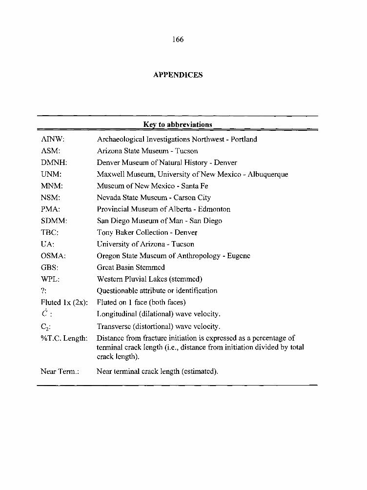
APPENDICES
Kev to abbreviations
AINW:
ASM:
DMNH:
UNM:
MNM:
NSM:
PMA:
SDMM:
TBC:
U A:
OSMA:
GBS:
WPL:
?:
Fluted l x (2x):
c : C, :
%T.C. Length:
Near Term.
Archaeological Investigations Northwest - Portland
Arizona State Museum - Tucson
Denver Museum of Natural History - Denver
Maxwell Museum, University of New Mexico - Albuquerque
Museum of New Mexico - Santa Fe
Nevada State Museum - Carson City
Provincial Museum of Alberta - Edmonton
San Diego Museum of Man - San Diego
Tony Baker Collection - Denver
University of Arizona - Tucson
Oregon State Museum of Anthropology - Eugene
Great Basin Stemmed
Western Pluvial Lakes (stemmed)
Questionable attribute or identification
Fluted on 1 face (both faces)
Longitudinal (dilational) wave velocity.
Transverse (distortional) wave velocity.
Distance from fracture initiation is expressed as a percentage of terminal crack length (i.e., distance from initiation divided by total crack length).
Near terminal crack length (estimated).
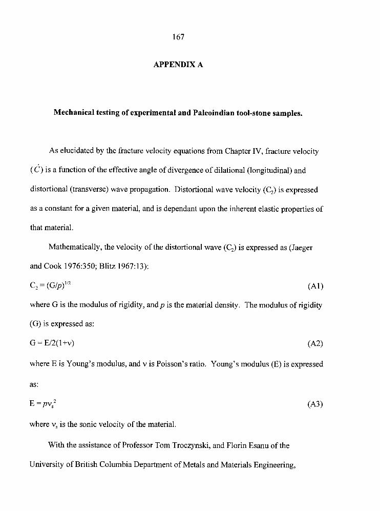
167
APPENDIX A
Mechanical testing of experimental and Paleoindian tool-stone samples.
As elucidated by the fracture velocity equations from Chapter IV, fracture velocity
( 6 ) is a function of the effective angle of divergence of dilational (longitudinal) and
distortional (transverse) wave propagation. Distortional wave velocity (C,) is expressed
as a constant for a given material, and is dependant upon the inherent elastic properties of
that material.
Mathematically, the velocity of the distortional wave (CJ is expressed as (Jaeger
and Cook 1976:350; Blitz 1967:13):
C, = (Glp)'I2 (A1
where G is the modulus of rigidity, andp is the material density. The modulus of rigidity
(G) is expressed as:
G = E/2(l+v) ( 4
where E is Young's modulus, and v is Poisson's ratio. Young's modulus (E) is expressed
as:
E =pv,2 (A31
where v, is the sonic velocity of the material.
With the assistance of Professor Tom Troczynski, and Florin Esanu of the
University of British Columbia Department of Metals and Materials Engineering,
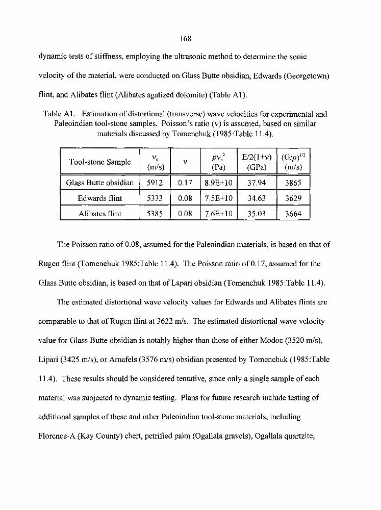
dynamic tests of stiffness, employing the ultrasonic method to determine the sonic
velocity of the material, were conducted on Glass Butte obsidian, Edwards (Georgetown)
flint, and Alibates flint (Alibates agatized dolomite) (Table Al).
Table A1 . Estimation of distortional (transverse) wave velocities for experimental and Paleoindian tool-stone samples. Poisson's ratio (v) is assumed, based on similar
materials discussed by Tomenchuk (1985:Table 11.4).
Tool-stone Sample
I I I I I
I Alibates flint 5385 0.08 7.6E+IO 35.03 3664
Glass Butte obsidian
Edwards flint
The Poisson ratio of 0.08, assumed for the Paleoindian materials, is based on that of
Rugen flint (Tomenchuk 1985:Table 1 1.4). The Poisson ratio of 0.17, assumed for the
Glass Butte obsidian, is based on that of Lapari obsidian (Tomenchuk 1985:Table 11.4).
The estimated distortional wave velocity values for Edwards and Alibates flints are
comparable to that of Rugen flint at 3622 mls. The estimated distortional wave velocity
value for Glass Butte obsidian is notably higher than those of either Modoc (3520 d s ) ,
Lipari (3425 mls), or Arnafels (3576 d s ) obsidian presented by Tomenchuk (1985:Table
11.4). These results should be considered tentative, since only a single sample of each
material was subjected to dynamic testing. Plans for future research include testing of
additional samples of these and other Paleoindian tool-stone materials, including
Florence-A (Kay County) chert, petrified palm (Ogallala gravels), Ogallala quartzite,
5912
5333
0.17
0.08
8.9E+10
7.5E+lO
37.94
34.63
3865
3629

169
Dakota quartzite, Flat Top flint, Spanish Diggings flint, Day Creek chert, Knife River
flint, and Smoky Hill Jasper (Niobrara).
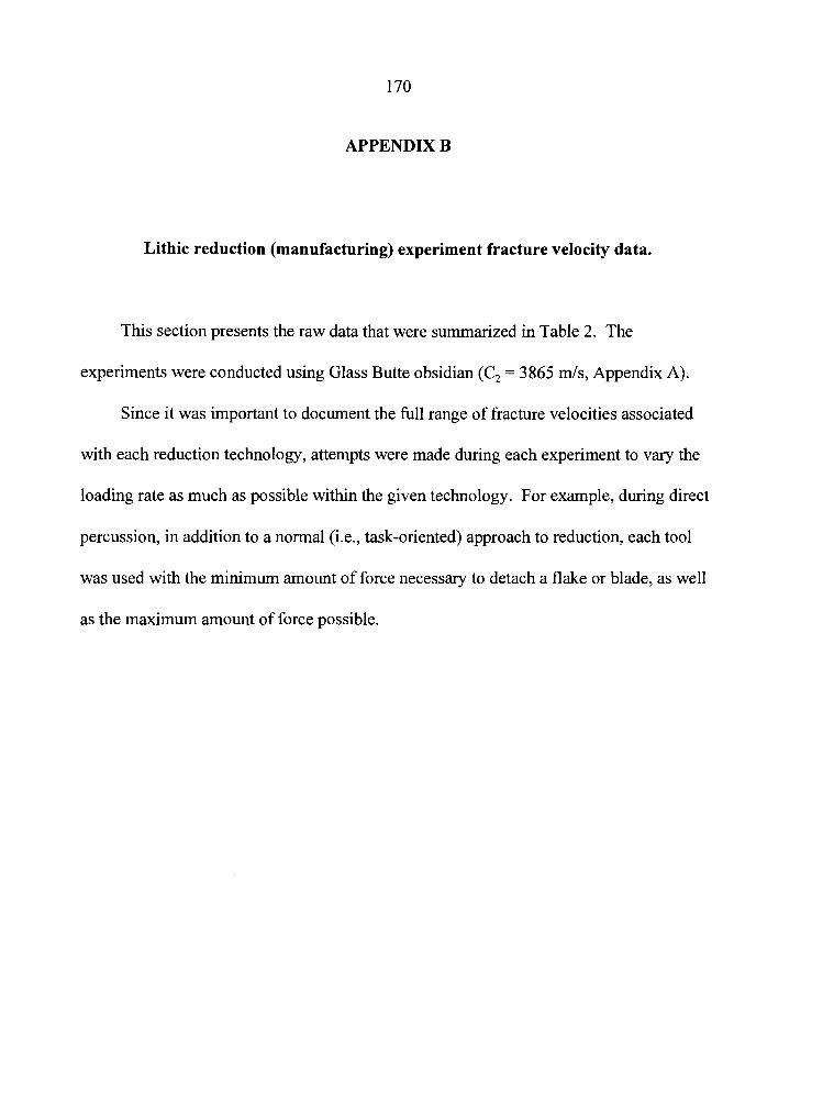
170
APPENDIX B
Lithic reduction (manufacturing) experiment fracture velocity data.
This section presents the raw data that were summarized in Table 2. The
experiments were conducted using Glass Butte obsidian (C, = 3865 mls, Appendix A).
Since it was important to document the full range of fracture velocities associated
with each reduction technology, attempts were made during each experiment to vary the
loading rate as much as possible within the given technology. For example, during direct
percussion, in addition to a normal (i.e., task-oriented) approach to reduction, each tool
was used with the minimum amount of force necessary to detach a flake or blade, as well
as the maximum amount of force possible.
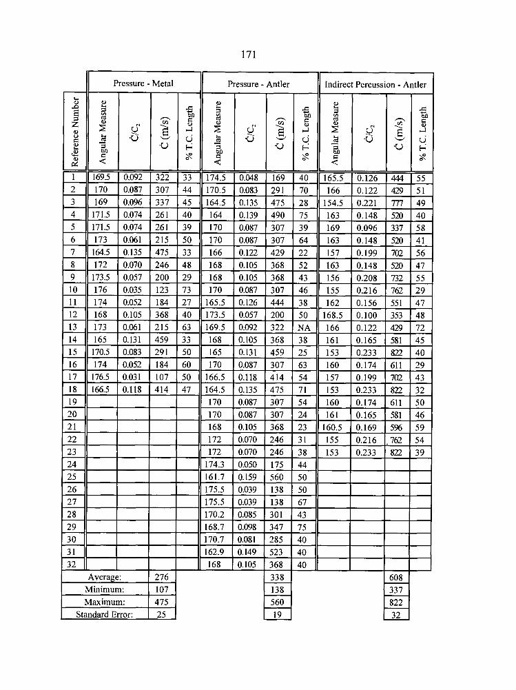
I( Pressure - Mia1 Pressure - Antler I I I
Indirect Percussion - Antler (
Average: Minimum: 1 107 1 Maximum:
Standard Error:
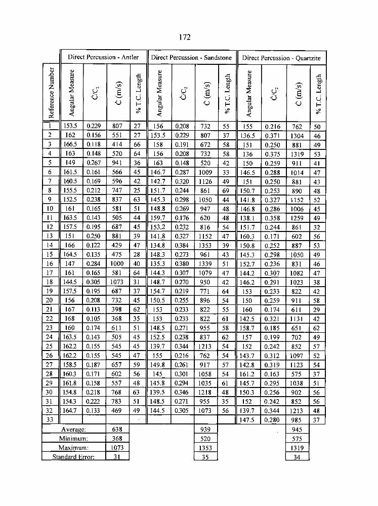
Direct Percussion - Antler Direct Percussion - Sandstone I I I
Direct Percussion - Quartzite
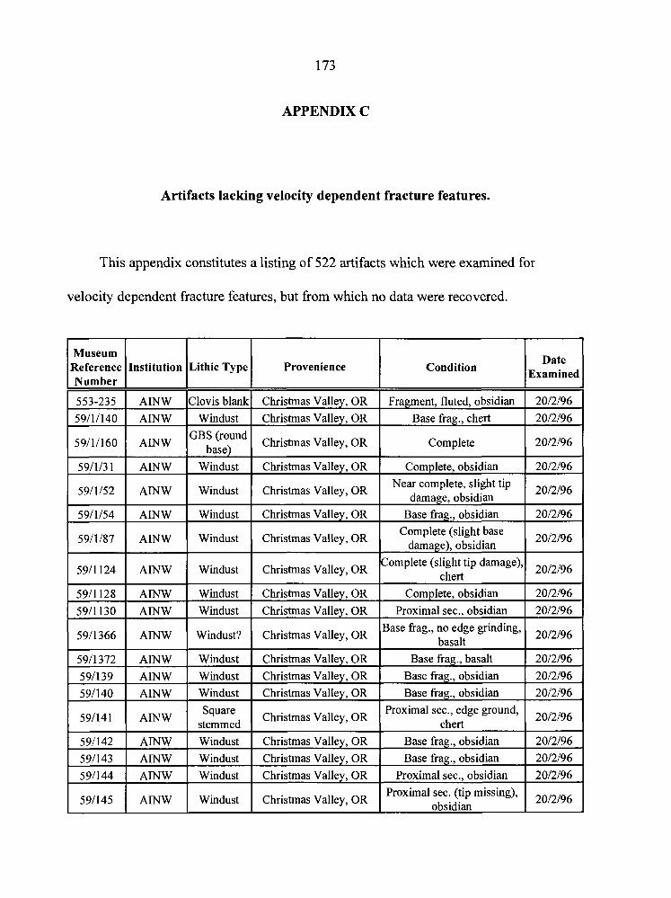
APPENDIX C
Artifacts lacking velocity dependent fracture features.
This appendix constitutes a listing of 522 artifacts which were examined for
velocity dependent fracture features, but from which no data were recovered.
59111160 1 AMW IGBE:f,";"d 1 Christmas Valley, OR I Complete
Museum teference Number
553-235
59111140
59/1/31 1 AINW I Windust I Christmas Valley, OR I Complete, obsidian
Lithic Type Institution
AINW AINW
59/1/54 1 AINW I Windust I Christmas Valley, OR I Base frag., obsidian
Provenience
59/1/52
Condition
Clovis blank
Windust
5911 124 1 AINW I Windust I Christmas Valley, OR I Complete (slight tip damage) chert
AINW
-
59/1/87
5911 128 1 AINW I Windust 1 Christmas Valley, OR I Complete, obsidian
Christmas Valley, OR Christmas Valley, OR
Fragment, fluted, obsidian
Base frag., chert
Windust
AINW
5911 130
5911366
5911372
591139
591140
591142 1 AINW I Windust I Christmas Vallev. OR I Base frag.. obsidian
Christmas Valley, OR
Windust
59/141
Near complete, slight tip damage, obsidian
AINW
AINW
AINW AINW AINW
Christmas Valley, OR
AINW
591143
591144
Date Examined
Complete (slight base damage), obsidian
Windust
Windust?
Windust Windust Windust
591145
Square stemmed
AINW AINW
Christmas Valley, OR
Christmas Valley, OR
Christmas Valley, OR
Christmas Valley, OR Christmas Valley, OR
AINW
Proximal sec., obsidian
Base frag., no edge grinding, basalt
Base frag., basalt Base frag., obsidian Base frag., obsidian
Christmas Valley, OR
Windust Windust
Proximal sec., edge ground, chert
Windust
Christmas Valley, OR Christmas Valley, OR
Base frag., obsidian
Proximal sec., obsidian
Christmas Valley, OR Proximal sec. (tip missing),
obsidian
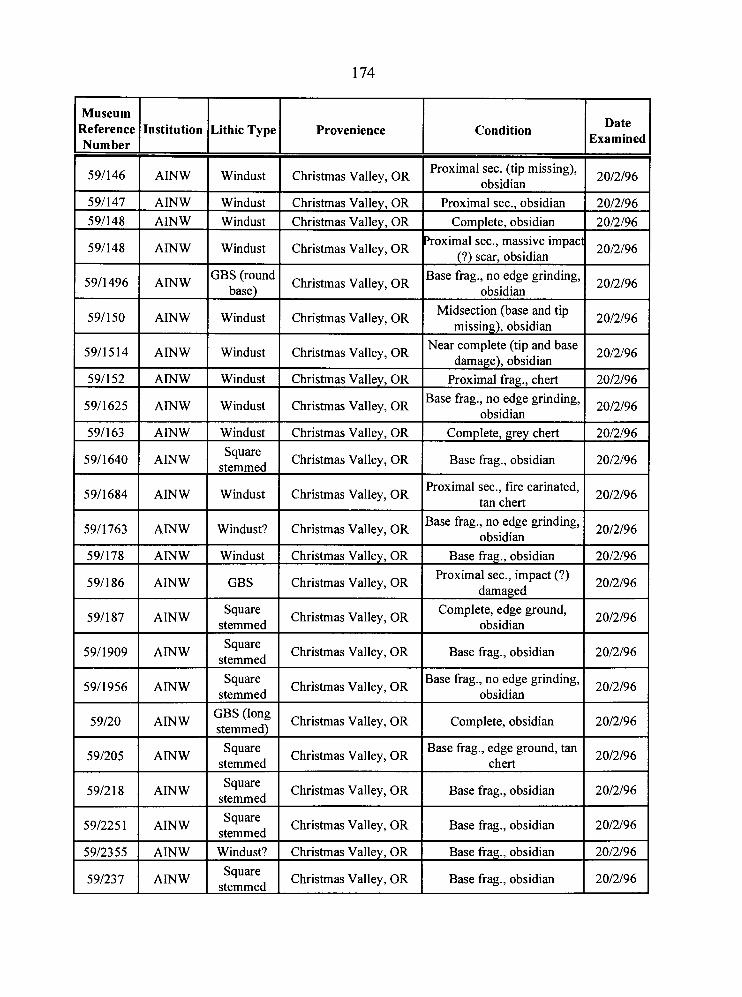
Museum teference Number
591147 1 AINW I Windust I Christmas Valley, OR I Proximal sec., obsidian 1 2012196
591146
591148 1 AINW I Windust I Christmas Valley, OR I Complete, obsidian 1 2012196
Institution
AINW
591163 1 AINW I Windust I Christmas Valley, OR 1 Complete, grey chert 1 2012196
Lithic Type
591148
5911496
5911 50
59/15 14
591152
5911625
Windust
Provenience
AINW
AMW
AINW
AINW
AINW
AINW
5911640
Christmas Valley, OR
5911684
591178 1 AINW I Windust I Christmas Valley, OR I Base frag., obsidian 1 2012196
Condition
Windust
GBS (round
Windust
Windust
Windust
Windust
AINW
5911763
Date Examined
Proximal sec. (tip missing), obsidian
AINW
2012196
Christmas Valley, OR
Christmas Valley, OR
Christmas Valley, OR
Christmas Valley, OR
Christmas Valley, OR
Christmas Valley, OR
Square stemmed
AINW
591186
Windust
591187
'roximal sec., massive impact (?) scar, obsidian
Base frag., no edge grinding, obsidian
Midsection (base and tip missing), obsidian
Near complete (tip and base damage), obsidian
Proximal frag., chert Base frag., no edge grinding,
obsidian
Christmas Valley, OR
Windust?
AINW
5911909
2012196
2012196
2012196
2012196
2012196
2012196
Christmas Valley, OR
AINW
5911956
Base frag., obsidian
Christmas Valley, OR
GBS
AINW
59120 I AINW
2012196
Proximal sec., fire carinated, tan chert
Square stemmed
AINW
591205
2012196
Base frag., no edge grinding, obsidian
Christmas Valley, OR
Square stemmed
GBS (long I Christmas Valley, OR I Complete, obsidian stemmed)
591218
5912355 1 AINW I Windust? I Christmas Valley, OR I Base frag., obsidian 1 2012196
2012196
Christmas Valley, OR
Square stemmed
2012196
AINW
591225 1
Proximal sec., impact (?) damaged
Christmas Valley, OR
AINW
2012196
Complete, edge ground, obsidian
Christmas Valley, OR
Square stemmed
AINW
591237
2012196
Base frag., obsidian
Square stemmed
2012196
Base frag., no edge grinding, obsidian
Christmas Valley, OR
Square stemmed
AINW
2012196
Christmas Valley, OR
Base frag., edge ground, tan chert
Christmas Valley, OR
Square stemmed
2012196
Base frag., obsidian 2012196
Base frag., obsidian
Christmas Valley, OR
2012196
Base frag., obsidian 2012196
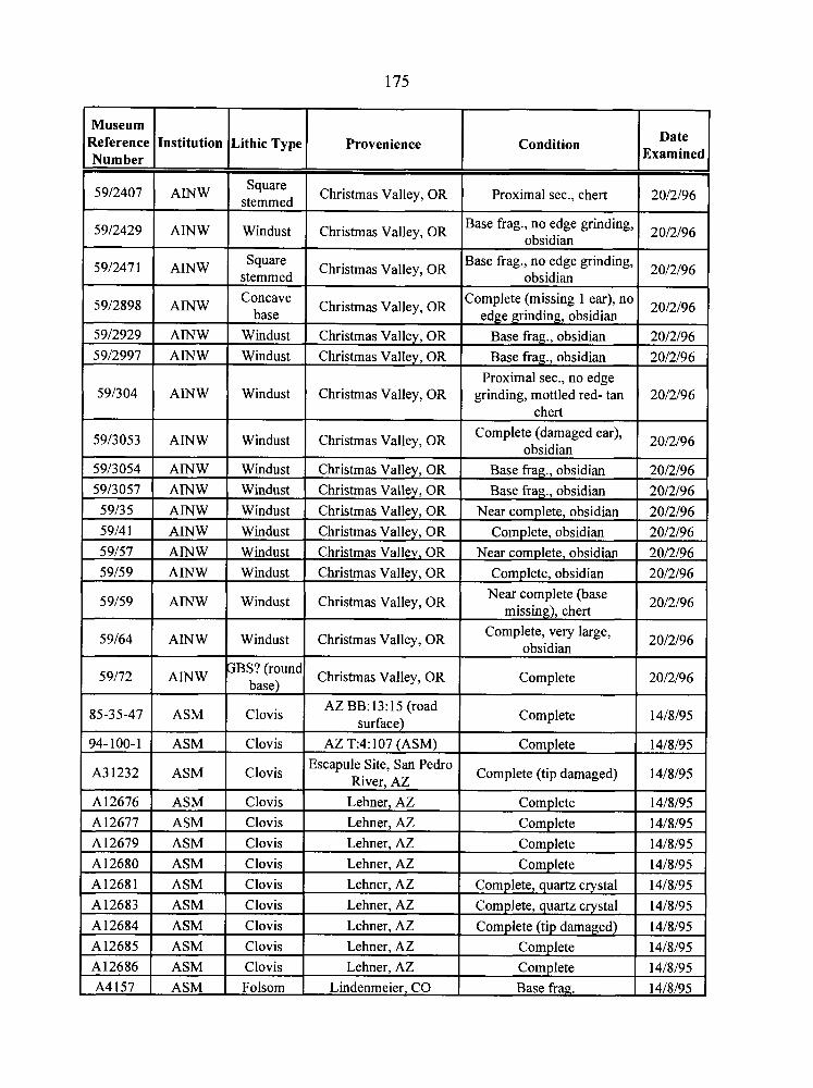
Museum Reference Number
5912407
5912429
5912471
5912898
5912929
5912997
591304
Institution
AINW
AINW
AINW
AINW
5913053
AINW
AINW
AINW
5913054
5913057
Lithic Type
Square stemmed
Windust
Square stemmed Concave
base
AINW
59/35 5914 1
59157 59/59
1 94-100-1 1 ASM I Clovis I AZ T:4:107 (ASM) I Complete 1 14/8/95 1
Windust Windust
Windust
AINW AINW
59/59
59164
59/72
85-35-47
Provenience
Christmas Valley, OR
Christmas Valley, OR
Christmas Valley, OR
Christmas Valley, OR
Windust
AINW AINW
AINW AINW
Christmas Valley, OR
Christmas Valley, OR
Christmas Valley, OR
Windust Windust
AINW
AINW
AINW
ASM
A3 1232
1 A12679 1 ASM I Clovis ( Lehner, AZ 1 Complete 1 1418195 1
Condition
Proximal sec., chert
Base frag., no edge grinding, obsidian
Base frag., no edge grinding, obsidian
Complete (missing 1 ear), no ed rindin , obsidian
Christmas Valley, OR
Windust
Windust Windust
Windust
A12676 A12677
Date Examined
2012196
2012196
2012196
2012196
Base frag., obsidian
Base fiag., obsidian Proximal sec., no edge
grinding, mottled red- tan chert
Christmas Valley, OR Christmas Valley, OR
Windust
Windust
"BS? (round
Clovis
:
ASM
2012196 2012196
2012196
Complete (damaged ear), obsidian
Christmas Valley, OR
Christmas Valley, OR Christmas Valley, OR Christmas Valley, OR
ASM ASM
A12680 A12681
2012196
Base frag., obsidian Base frag., obsidian
Christmas Valley, OR
Christmas Valley, OR
Christmas Valley, OR
AZ BB:13:15 (road surface)
Clovis
A12683
A12684 A12685 A12686 A4157
2012196 2012196
Near complete, obsidian Complete, obsidian
Near complete, obsidian
Complete, obsidian
Clovis Clovis
ASM ASM
2012196 2012196
2012196 2012196
Near complete (base missing), chert
Complete, very large, obsidian
Complete
Complete
Escapule Site, San Pedro River, AZ
ASM
ASM ASM ASM ASM
2012196
2012196
2012196
14/8/95
Lehner, AZ Lehner, AZ
Clovis Clovis
Complete (tip damaged)
Clovis
Clovis Clovis Clovis Folsom
14/8/95
Complete Complete
Lehner, AZ Lehner, AZ
14/8/95 14/8/95
Lehner, AZ
Lehner, AZ
Lehner, AZ Lehner, AZ
Lindenmeier. CO
Complete
Complete, quartz crystal
14/8/95
14/8/95
Complete, quartz crystal
Complete (tip damaged) Complete Complete Base frag.
14/8/95
14/8/95 14/8/95 14/8/95 14/8/95
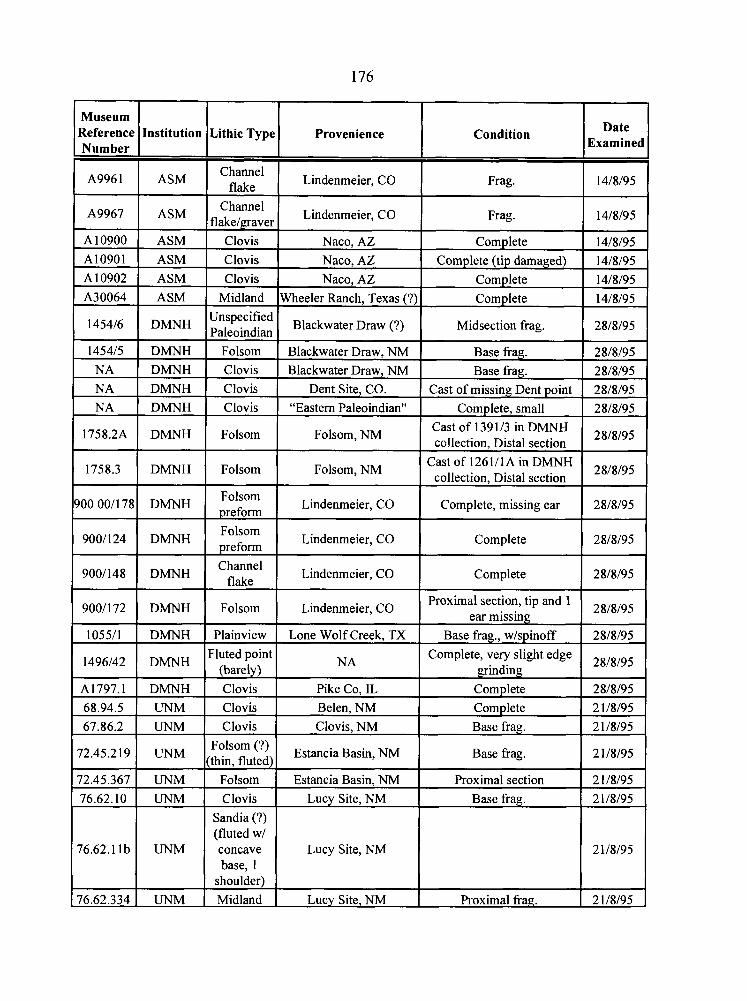
1 Number I I I I
Museum IReference Date
Examine Institution
A996 1
A9967
Lithic Type
A10900 A10901
ASM
A10902 A30064
NA I DMNH ( Clovis I Blackwater Draw, NM I Base frag. 1 28/8/95
Provenience
ASM ASM
1454/6
145415
Condition
Channel flake
Channel flakelgraver
ASM ASM
Clovis Clovis
DMNH
NA NA
Lindenmeier, CO
Lindenmeier, CO
Clovis Midland
1758.2A
1758.3
9001148 1 DMNH I 1 Lindenmeier, CO I Complete
Naco, AZ Naco, AZ
Unspecified Paleoindian
Folsom
DMNH DMNH
900 00/178
9001124
Frag.
Frag.
Naco, AZ Wheeler Ranch, Texas (?)
DMNH
DMNH
105511 ( DMNH I Plainview 1 Lone Wolf Creek, TX ( Base frag., wlspinoff 1 28/8/95
14/8/95
14/8/95
Complete
Complete (tip damaged)
Blackwater Draw (?)
Blackwater Draw, NM
Clovis Clovis
DMNH
DMNH
9001172
14/8/95 14/8/95
Complete Complete
Folsom
Folsom
14/8/95 14/8/95
Midsection frag.
Base frag.
Dent Site, CO. "Eastern Paleoindian"
Folsom
Folsom Drefom
DMNH
1496142
67.86.2 1 UNM I Clovis I Clovis, NM 1 Base frag. 1 21/8/95
28/8/95
28/8/95
Folsom, NM
Folsom, NM
A1797.1 68.94.5
Cast of missing Dent point Complete, small
Lindenrneier, CO
Lindenmeier, CO
Folsom
DMNH
28/8/95 28/8/95
Cast of 139 113 in DMNH collection, Distal section
Castof1261/1AinDMNH collection, Distal section
DMNH UNM
Folsom (?) I Estancia Basin, NM I 72'45'2 1 UNM I(thin, fluted) Base frag.
76.62.334 1 UNM 1 Midland I Lucy Site, NM I Proximal frag. 1 21/8/95
28/8195
28/8/95
Complete, missing ear
Complete
Lindenmeier, CO
Fluted point (barel )
2 1/8/95
72.45.367 76.62.10
76.62.11b
28/8/95
28/8/95
Proximal section, tip and 1 ear missing
Clovis Clovis
NA
UNM UNM
UNM
Pike Co, IL Belen, NM
Complete, very slight edge grinding
Folsom Clovis
Sandia (?) (fluted w/ concave base, 1
28/8/95
Complete Complete
28/8/95 2 1/8/95
Estancia Basin, NM Lucy Site, NM
Lucy Site, NM
Proximal section Base frag.
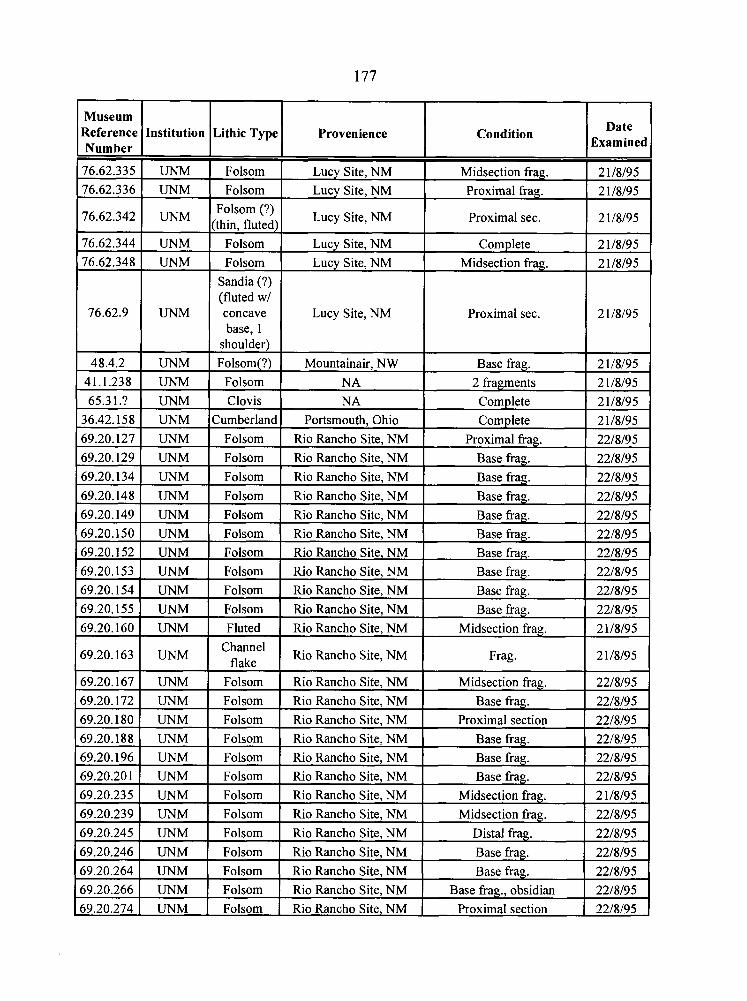
177
Proximal sec.
69.20.266 1 UNM I Folsom I Rio Rancho Site, NM I Base fiag., obsidian 1 22/8/95 69.20.274 1 UNM I Folsom 1 Rio Rancho Site, NM ( Proximal section 1 22/8/95 -
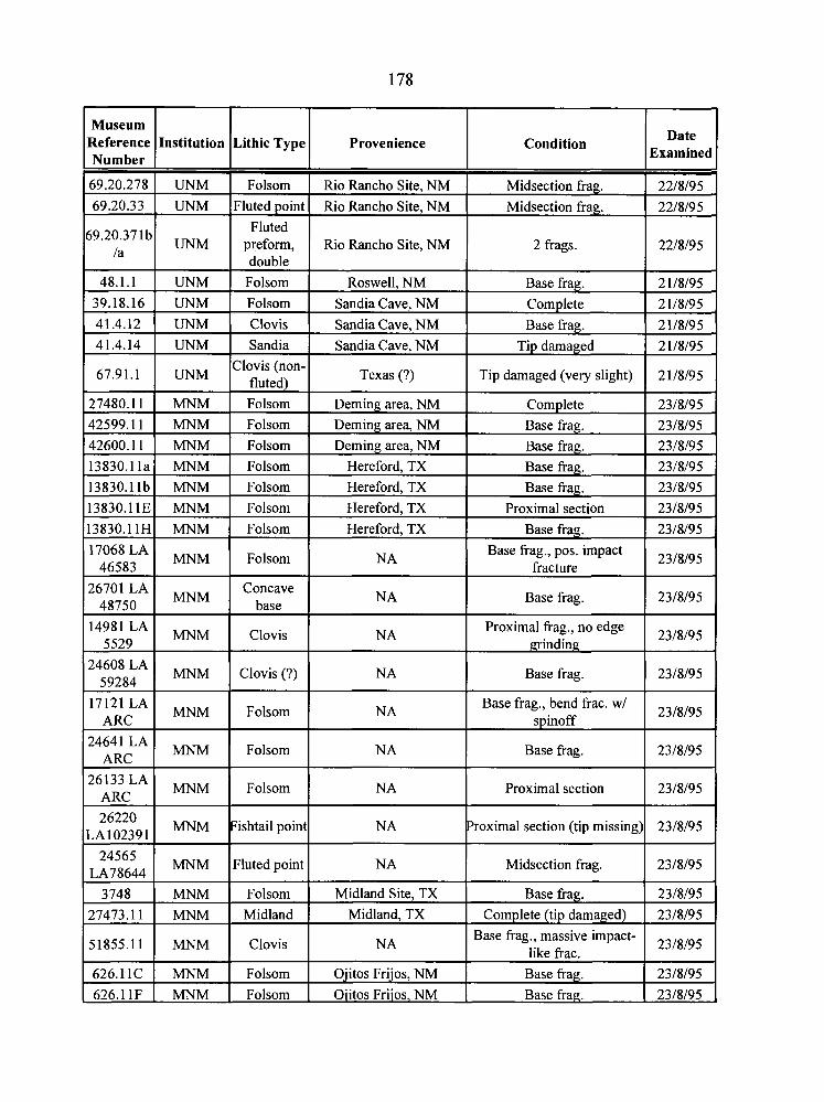
Reference I Institution I Lithic Typr
69.20.33 1 UNM I~luted poinl
Number
69.20.278
Fluted
double 48.1.1 1 UNM I Folsom
UNM
39.18.16 1 UNM I Folsom
Folsom
Clovis (non. 67.91'1 1 UNM I fluted)
41.4.12 41.4.14
27480.1 1 zi Folsom 42599.1 1 Folsom 42600.1 1 Folsom 13830.11a MNM Folsom 13830.11b MNM Folsom
UNM UNM
Clovis Sandia
13830.11E 13830.11H 17068 LA
46583
MNM MNM
14981LA 5529
24608 LA 59284
17121 LA ARC
24641 LA ARC
26133 LA ARC
24565 1 MNM IFluted poinl LA78644
Folsom Folsom
MNM
26220 LA 10239 1
Folsom
51855.11 Clovis
Folsom
MNM
MNM
MNM
MNM
mM
626.11C 1 MNM I Folsom
Clovis
Clovis (?)
Folsom
Folsom
Folsom
MNM
626.1 1F 1 MNM I Folsom
Fishtail poin
Provenience
Rio Rancho Site, NM I 2 frags.
Rio Rancho Site, NM Rio Rancho Site, NM
Condition Date Examinec
Midsection frag. Midsection frag.
Roswell, NM Sandia Cave. NM
22/8/95 22/8/95
Sandia Cave, NM Sandia Cave, NM
Texas (?)
Hereford, TX 1 Base frag. 1 23/8/95
Base frag. Com~lete
Deming area, NM Deming area, NM Deming area, NM
2 1/8/95 2 1/8/95
Base frag. Tip damaged
Tip damaged (very slight)
21/8/95 2 1/8/95
2 1/8/95
Complete Base frag. Base frag.
Hereford, TX Hereford, TX Hereford. TX
NA 1 Base frag. I 23/8/95
23/8/95 23/8/95 23/8/95
NA
Base frag. Proximal section
Base frac.
NA I Base fiag. 1 23/8/95
23/8/95 23/8/95 23/8/95
Base frag., pos. impact fracture
NA
23/8/95
Proximal frag., no edge grinding
NA
23/8/95
NA
NA
Base frag., bend frac. w/ spinoff
NA
NA
23/8/95
Base frag.
Proximal section
Midland Site, TX Midland, TX
Ojitos Frijos, NM 1 Base frag. 1 23/8/95
23/8/95
23/8/95
Proximal section (tip missing)
Midsection frag.
NA
Oiitos Friios, NM I Base frag. 1 23/8/95
23/8/95
23/8/95
Base frag. Complete (tip damaged)
23/8/95 23/8/95
Base frag., massive impact- like frac. 23/8/95
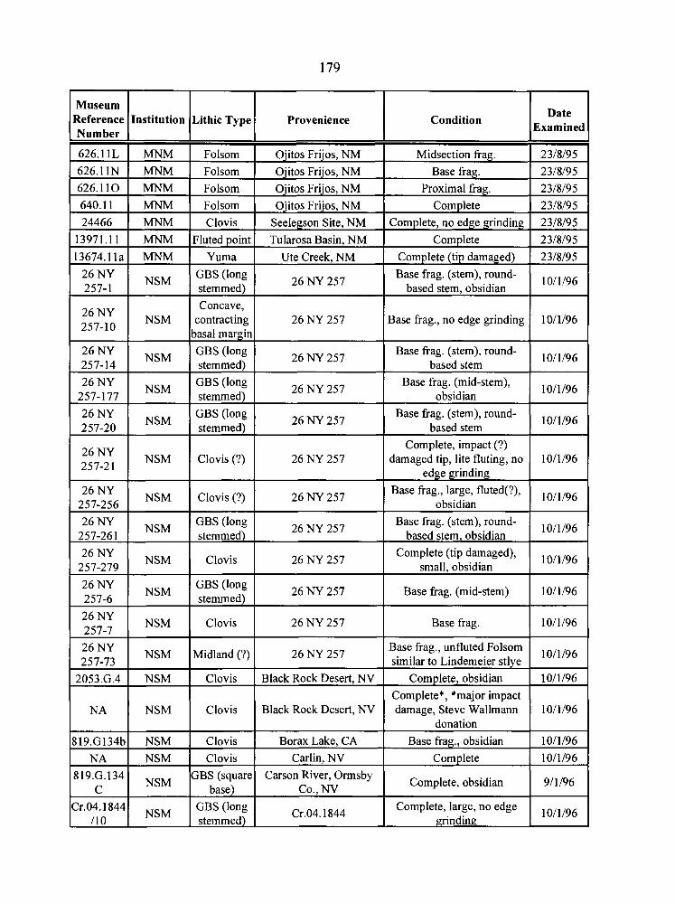
626.1 1N 1 MNM I Folsom 1 Ojitos Frijos, NM 1 Base frag.
Museum Reference Number
626.11L
Institution
MNM
626.1 1 0
640.1 1
24466
13 97 1.1 1
13674.11a
MNM
MNM
MNM
26 NY 257-1
Condition
Midsection frag.
Lithic Type
Folsom
MNM
MNM
26 NY 257-10
Provenience
Ojitos Frijos, NM
Folsom
Folsom
Clovis
GBS (long NSM 1 stemmed)
26 NY 257-14
Fluted point
Yuma
NSM
26 NY GBS (long 26 NY 257
257-177 I NSM 1 stemmed) 1
Ojitos Frijos, NM
Ojitos Frijos, NM
Seelegson Site, NM
26 NY 257
NSM
Base frag. (mid-stem), obsidian
26 NY 257-20
Proximal frag.
Complete
Complete, no edge grinding
Tularosa Basin, NM
Ute Creek, NM
Base frag. (stem), round- based stem, obsidian
Concave, contracting
basal margin
26 NY 257-2 1
Complete
Complete (tip damaged)
GBS (long stemmed)
NSM
26 NY I NSM I ~ l o v i s (7) I 26 NY 257 257-256
26 NY 257
NSM
Base frag., large, fluted(?), obsidian
26 NY 257-26 1 1 NSM
Base frag., no edge grinding
26 NY 257
GBS (long stemmed)
26 NY 257-279
26 NY 257-6
26 NY I NSM IMidland (?) 1 26 NY 257 1 Base frag., unfluted Folsom 257-73 similar to Lindemeier stlve
Base frag. (stem), round- based stem
Clovis (?)
GBS (long stemmed)
26 NY 257-7
26 NY 257
NSM
NSM
Base frag. (stem), round- based stem
26 NY 257
26 NY 257
NSM
2053.G.4
NA
Complete, impact (?) damaged tip, lite fluting, no
edge grinding
Base frag. (stem), round- based stem, obsidian
Clovis
GBS (long stemmed)
819.G134b
NA
Clovis
NSM
NSM
819.G.134 C
Date Examined
26 NY 257
26 NY 257
- -
NSM
NSM
Cr.04.1844 I10
Complete (tip damaged), small, obsidian
Base frag. (mid-stem)
26 NY 257
Clovis
Clovis
NSM
Base frag.
Clovis
Clovis
NSM
Black Rock Desert, NV
Black Rock Desert, NV
GBS (square base)
Complete, obsidian
Complete*, *major impact damage, Steve Wallmann
donation
Borax Lake, CA
Carlin, NV
GBS (long stemmed)
Base frag., obsidian
Complete Carson River, Ormsby
Co., NV Complete, obsidian
Cr.04.1844 Complete, large, no edge
grinding
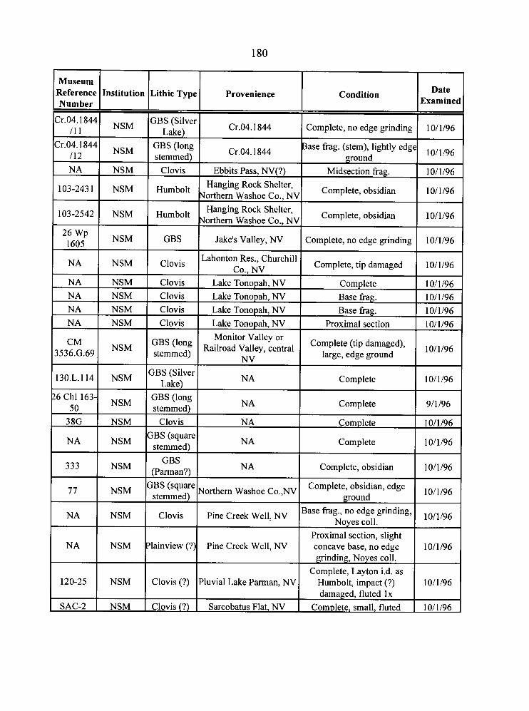
Number I Museum Reference
NA NSM
Institutior
103-2431 1 NSM
103-2542 1 NSM
NA 1 NSM
CM I NSM 1536.G.69
13O.L.114 NSM
NA NSM
qe SAC-2 NSM
GBS I Cr.04.1844 I Complete, no edge grinding I .&el
Lithic Type Provenience
Clovis I Ebbits Pass, NV(?) I Midsection frag. 1 1011196
GBS (long stemmed) Cr.04.1844 ase frag. (stem), lightly edge
ground
Humbolt
1011196
Humbolt
Hanging Rock Shelter, Northern Washoe Co., NV
GBS
Hanging Rock Shelter, Northern Washoe Co., NV
Clovis
Clovis I Lake Tonopah, NV I Proximal section 1 1011196
Complete, obsidian
Jake's Valley, NV
Clovis Clovis
Clovis
Monitor Valley or GBS (long Railroad Valley, central stemmed) I NV
1011196
Complete, obsidian
Lahonton Res., Churchill Co., NV
1011196
Complete, no edge grinding
Lake Tonopah, NV Lake Tonopah, NV
Lake Tonopah, NV
1011196
Complete, tip damaged
Complete (tip damaged), large, edge ground
GBS (long stemmed) NA Complete 9/1/96
1011196
Complete Base frag. Base frag.
1011196
3BS (Silver Lake)
Clovis I NA Complete 1 1011/96
10/1/96 10/1/96
1011196
3BS (square stemmed) NA Complete 1011196
NA
I Complete, obsidian 1 1011196
3BS (square Northern Washoe Co.,NV Complete, obsidian, edge
stemmed) ground
Complete
Clovis Pine Creek Well, NV Base frag., no edge grinding, Noyes coll.
10/1/96
10/1/96
Proximal section, slight concave base, no edge grinding, Noyes coll.
Complete, Layton i.d. as Humbolt, impact (?) damaged. fluted l x
'lainview (?)
Clovis (?)
Clovis (?) Complete, small, fluted 1 1011196
Pine Creek Well, NV
Pluvial Lake Parman, NV
Sarcobatus Flat, NV
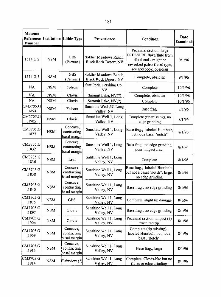
Provenience Museum
Date Athic Type Condition Sxamine
Proximal section, large PRESSURE flake/flute from
distal end - might be reworked paleo-fluted type,
see notebook, obsidian
Complete, obsidian
GBS (Parman)
Soldier Meadows Ranch, Black Rock Desert, NV
1514.G.2 NSM I I I 1511G.3 I NSM GBS (Parman)
Folsom
Soldier Meadows Ranch, Black Rock Desert, NV Star Peak, Pershing Co.,
NV Summit Lake, NV(?) Summit Lake, NV(?)
Sunshine Well ,3C Long Valley, NV
Sunshine Well 1, Long Valley, NV
Sunshine Well 1, Long Valley, NV
Complete t++ NSM
Clovis Complete, obsidian Complete Clovis
Folsom Base frag.
Clovis
Concave, :ontracting asal margin Concave, ;ontracting asal margin
Leaf
Complete (tip missing), no edge grinding
3ase frag., labeled Humbolt, but not a basal "notch"
3ase frag., no edge grinding, poss. impact frac.
Sunshine Well 1, Long Valley, NV
Sunshine Well 1, Long Valley, NV Complete
Concave, :ontracting asal margin Concave, :ontracting asal margin
GBS
3ase frag., labeled Humbolt, ~u t not a basal "notch", large,
no edge grinding
Sunshine Well 1, Long Valley, NV
Sunshine Well 1, Long Valley, NV Base frag., no edge grinding
Sunshine Well 1, Long Valley, NV
Sunshine Well 1, Long Valley, NV
Sunshine Well 1, Long Vallev. NV
Complete, slight tip damage
Clovis Base frag., no edge grinding
Proximal section, impact (?) fractured tip
Complete (tip missing), labeled Humbolt, but not a
basal "notch"
Clovis
Concave, :ontracting asal margin Concave, :omacting asal margin
ainview (?)
Sunshine Well 1, Long Valley, NV
Sunshine Well 1, Long Valley, NV
Sunshine Well 1, Long Valley, NV
Base frag., large
r:zGI NSM :omplete, Clovis-like but no flutes or edge grinding
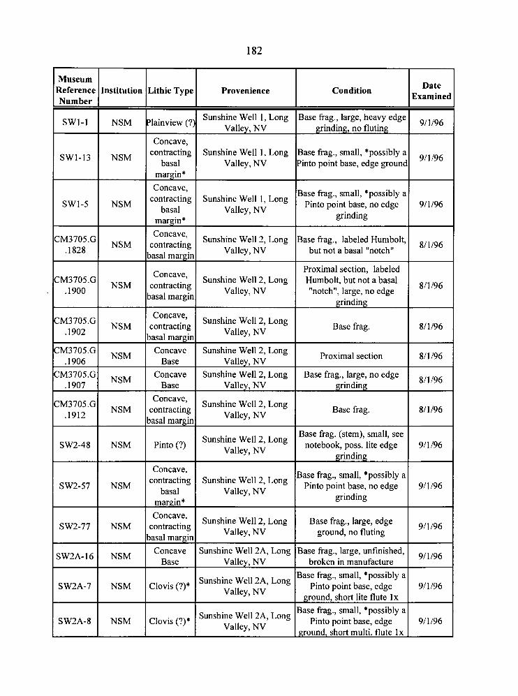
Museum Reference Institution Lithic Type Provenience Number
Date Sxamined
9/1/96
Condition
SWl-1 NSM ?lainview (?) Sunshine Well 1, Long
Valley, NV Base frag., large, heavy edge
grinding, no fluting
I I concave, I contracting Sunshine Well 1, Long
SW1-13 I NSM I basal I Valley, NV 3ase frag., small, *possibly a 'into point base, edge grounc
margin* Concave,
3ase frag., small, *possibly a Pinto point base, no edge
grinding
3ase frag., labeled Humbolt, but not a basal "notch"
contracting Sunshine Well 1, Long SW1-5 I NSM I basal I Valley, NV
I I margin* I Concave, 2M3705.G
NSM Sunshine Well 2, Long
,1828 contracting basal margin Valley, NV
Proximal section, labeled Hurnbolt, but not a basal "notch", large, no edge
- grinding
Concave, 2M3705.G
NSM contracting Sunshine Well 2, Long
.I900 Valley, NV basal margin
Concave, ZM3705.Gl NsM 1 I Sunshine Well 2, Long
.I902 contracting
basal margin Valley, NV Base frag.
ZM3705.G NSM
Concave Sunshine Well 2, Long .I906 Base Valley, NV
Proximal section
2 ~ 3 7 0 5 . ~ 1 NSM I Concave .I907 Base
Base frag., large, no edge grinding
Concave, ZM3705.G NSM
Sunshine Well 2, Long .I912
contracting basal margin Valley, NV
Base frag.
Base fiag. (stem), small, see notebook, poss. lite edge
grinding
3ase frag., small, *possibly a Pinto point base, no edge
grinding
Sunshine Well 2, Long SW2-48 I NSM I Pinto (?) I
Valley, NV I I I
I Concave, I contracting Sunshine Well 2, Long
SW2-57 I NSM I basal I Valley, NV I I margin* I
Concave, SW2-77 NSM contracting
Sunshine Well 2, Long
basal margin Valley, NV
Base frag., large, edge ground, no fluting
Sunshine Well 2A, Long SW2A-16 1 NSM I C:z I Vallev. NV
3ase frag., large, unfinished, broken in manufacture
Sunshine Well 2A, Long SW2A-7 I NSM I Clovis (?)* I Valley, NV
3ase frag., small, *possibly a Pinto point base, edge
ground, short lite flute l x 3ase frag., small, *possibly a
Pinto point base, edge ground, short multi. flute l x
Sunshine Well 2A, Long SW2A-8 1 NSM I Clovis (?I* / Valley, NV
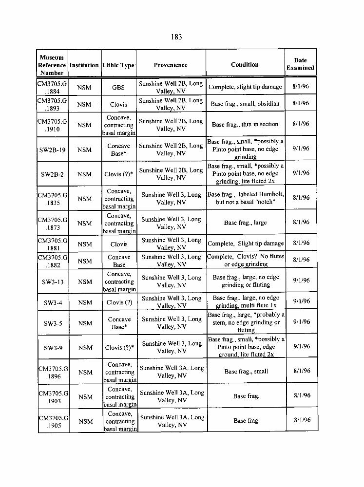
Date Examined
8/1/96
8/1/96
8/1/96
9/1/96
9/1/96
811/96
8/1/96
8/1/96
811196
9/ 1 196
9/1/96
9/1/96
9/1/96
8/1/96
8/1/96
8/1/96
Condition
Complete, slight tip damage
Base frag., small, obsidian
Base frag., thin in section
Base frag., small, *possibly a pinto point base, no edge
grinding
Base frag., small, *possibly a Pinto point base, no edge
grinding, lite fluted 2x
Base frag., labeled Humbolt, but not a basal "notch"
Base fiag., large
Complete, Slight tip damage
Complete, Clovis? No flutes or edge grinding
Base frag., large, no edge grinding or fluting
Base frag., large, no edge grinding, multi flute l x
Base frag., large, *probably a stem, no edge grinding or
fluting Base frag., small, *possibly a
Pinto point base, edge ground, lite fluted 2x
Base fiag.,
Base fiag.
Base frag.
Museum Reference Number
CM3705.G .I884
CM3705.G .I893
CM3705.G .I910
SW2B-19
SW2B-2
CM3705.G .I835
CM3705.G .I873
CM3705.G .I881
CM3705.G .I882
SW3-13
SW3-4
SW3-5
SW3-9
CM3705.G .I896
CM3705.G .I903
CM3705.G .I905
Institution
NSM
NSM
NSM
NSM
NSM
NSM
NSM
NSM
NSM
NSM
NSM
NSM
NSM
NSM
NSM
NSM
Lithic Type
GBS
Clovis
Concave, contracting
basal margin
Base*
Clovis (?)*
Concave, contracting
basal margin Concave,
contracting basal margin
Clovis
Concave Base
Concave, contracting
basal margin
Clovis (?)
Base*
Clovis (?)*
Concave, contracting
basal margin Concave,
contracting basal margin
Concave, contracting
basal margin
183
Provenience
Sunshine 2B' Long Valley, NV
Sunshine 2B' Long Valley, NV
Sunshine 2B' Long Valley, NV
Sunshine 2B, Valley, NV
Sunshine 2B' Long Valley, NV
Sunshine Well 3, Long Valley, NV
Sunshine Well 3, Long Valley, NV
3' Long Valley, NV
Sunshine Well 3, Long Valley, NV
Sunshine Well 3, Long Valley, NV
Sunshine Well 3, Long Valley, NV
Sunshine 37 Long Valley, NV
Sunshine 3' Long Valley, NV
Sunshine Well 3A, Long Valley, NV
Sunshine Well 3A, Long Valley, NV
Sunshine Well 3A, Long Valley, NV
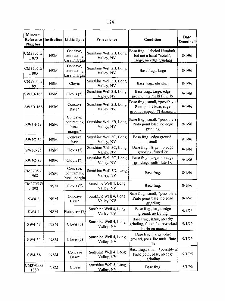
Museum Provenience Condition
Date Reference Institution Lithic Type Examined Number
Concave, Base frag., labeled Humbolt, CM3705.G NSM contracting
Sunshine 3B> but not a basal tOnotchU, .I829 Valley, NV
8/ 1/96 basal margin Large, no edge grinding
Concave, CM3705.G
NSM Sunshine Well 3B, Long
contracting Base frag., large .I883 Valley, NV
8/1/96 basal margin
CM3705.G NSM Clovis
Sunshine Well 3B, Long Base frag., obsidian .I891 Valley, NV
8/1/96
SW3B-165 NSM Clovis (?) Sunshine Well 3B, Long Base frag., large, edge
Valley, NV ground, lite multi flute l x 9/1/96
Base frag., small, *possibly a Concave Sunshine Well 38, Long Pinto point base, edge SW3B-166 NSM Base* Valley, NV
9/ 1 196 ground, impact (?) damaged
Concave, Base frag., small, *possibly a SW3B-79 NSM
contracting Sunshine Well 38, Long Pinto point base, no edge basal Valley, NV
9/1/96 grinding
margin*
SW3C-64 NSM Concave Sunshine Well 3C, Long Base frag., edge ground,
Base Valley, NV small 9/1/96
Sunshine Well 3C, Long Base frag., large, no edge SW3C-85 NSM Clovis (?) Valley, NV grinding, fluted 2x
9/1/96
Sunshine Well 3C, Long Base frag., large, no edge SW3C-89 NSM Clovis (?) Valley, NV grinding, multi flute l x
9/1/96
Concave, CM3705.G NSM
Sunshine Well 3D, Long contracting Base frag. Valley, NV
8/1/96 .I908 basal margin
CM3705.G NSM
Sunshine Well 4, Long Clovis (?) Base frag. Valley, NV
8/1/96 .I892
Base frag., small, *possibly a 'Oncave Sunshine 47 Long Pinto point base, no edge 9/1/96 SW4-2 NSM Base* Valley, NV grinding
Sunshine Well 4, Long Base frag., large, edge SW4-4 NSM ?lainview (?) Valley, NV ground, no fluting
9/l 196
Base frag., large, no edge SW4-49 NSM Clovis (?) grinding, fluted 2x, reworked 9/1/96
Sunshine Well 4, Long Valley, NV - burin on margin
Base frag., large, edge SW4-54 NSM Clovis (?) Sunshine 4' Long ground, poss. lite multi flute 9/1/96
Valley, NV lx
Base frag., small, *possibly a Sunshine 4> Long pinto point base, no edge 9/1/96 SW4-56 NSM Base* Valley, NV grinding
CM3705.G NSM
Sunshine Well 5, Long Clovis Base frag. 8/1/96
.I880 Valley, NV
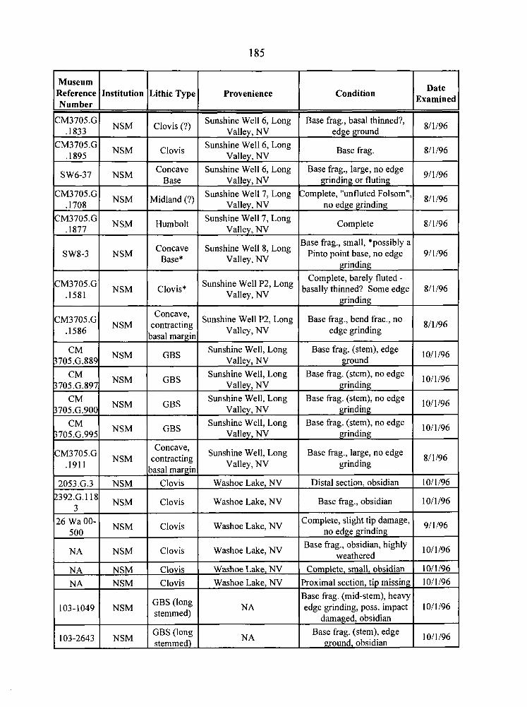
Museum Condition Date
Examined Lithic Type Provenience
Clovis (?) Sunshine Well 6, Long Base frag., basal thinned?, 81 1/96
Base frag. 8/1/96
Valley, NV
Clovis Sunshine Well 6, Long
Valley, NV Sunshine Well 6, Long Concave
Base
Midland (?)
Humbolt
Base frag., large, no edge grinding or fluting
91 1/96 SW6-37 ( NSM Valley, NV
Sunshine Well 7, Long Valley, NV
Sunshine Well 7, Long Valley, NV
Sunshine Well 8, Long Valley, NV
Sunshine Well P2, Long Valley, NV
Complete, "unfluted Folsom", no edge grinding
81 1/96
Complete 1 8/1/96
SW8-3 I NSM Concave
Base*
Base frag., small, *possibly a Pinto point base, no edge 9/1/96
grinding Complete, barely fluted -
basally thinned? Some edge 8/1/96 grinding
Base frag., bend frac., no edge grinding
8/1/96
Clovis*
Concave, contracting
basal margin
GBS
Sunshine Well P2, Long Valley, NV
Sunshine Well, Long Base frag. (stem), edge ground
10/1/96 CM I NSM 705.G.889 Valley, NV
NSM
GBS Sunshine Well, Long
Valley, NV Sunshine Well, Long
Base frag. (stem), no edge grinding
1011/96 -
GBS Base frag. (stem), no edge 10/1/96
grinding Valley, NV
I NSM 705.G.995
GBS Sunshine Well, Long
Valley, NV Base frag. (stem), no edge
grinding 10/1/96
Base frag., large, no edge grinding
81 1/96 Concave,
contracting basal margin
Clovis
Clovis
Sunshine Well, Long Valley, NV
Washoe Lake, NV
Washoe Lake, NV Base frag., obsidian 10/1/96
Clovis Washoe Lake, NV
Washoe Lake, NV
Complete, slight tip damage, no edge grinding
9/1/96 l6 gF-/ NSM
Clovis Base frag., obsidian, highly
weathered 10/1/96
Complete, small, obsidian 1011196 Proximal section, tip missing 10/1/96
Base frag. (mid-stem), heavy edge grinding, poss. impact 1011 196
I damaged, obsidian Base frag (stem), edge
I ground, obsidian 10/1/96
NA I NSM
Clovis Clovis
Washoe Lake, NV Washoe Lake, NV
GBS (long stemmed)
103-2643 1 NSM GBS (long stemmed)
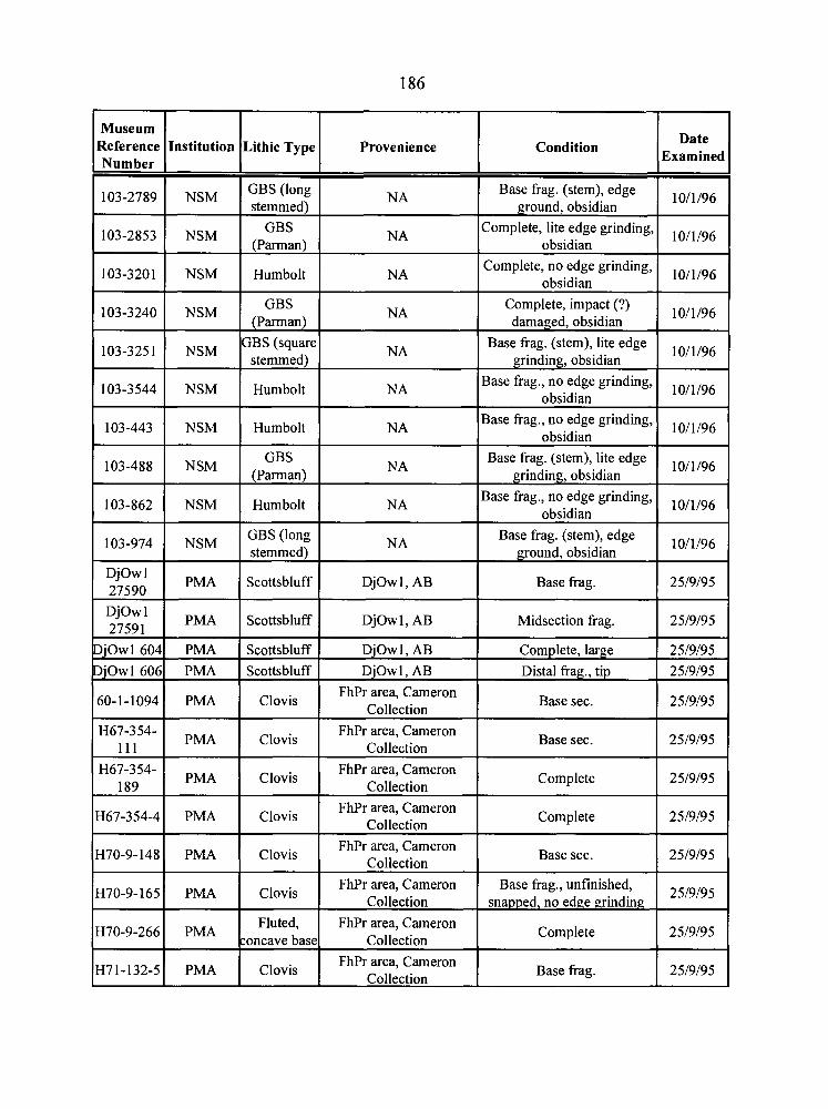
Museum Reference Number
103-2789
103-2853
103-3201
103-3240
103-325 1
103-3544
Institution
103-443
NSM
NSM
NSM
NSM
NSM
NSM
103-488
Lithic Type
NSM
103-862
GBS (long
GBS (Parman)
Humbolt
GBS (Parman)
GBS (square stemmed
Humbolt
NSM
103-974
DJowl 27590
Provenience
Humbolt
NSM
Djowl 27591
DjOwl 604
DjOwl 606
60- 1 - 1094
NA
NA
NA
NA
NA
NA
GBS (Parman)
NSM
PMA
H67-354- 111
H67-354- 189
H67-354-4
H70-9-148
Condition
NA
Humbolt
PMA
PMA PMA
PMA
Date Examined
Base frag. (stem), edge ground, obsidian
Complete, lite edge grinding, obsidian
obsidian Complete, no edge grinding,
Complete, impact (?) damaged, obsidian
Base frag. (stem), lite edge grinding, obsidian
Base frag., no edge grinding, obsidian
NA
GBS (long
Scottsbluff
H70-9-165 PMA FhPr area, Cameron Base frag., unfinished, Clovis Collection snapped, no edge grinding 25/9/95
Fluted, FhPr area, Cameron H70-9-266 concave base Collection Complete 25/9/95
H7 1 - 132-5 PMA Base frag. 25/9/95 FhPr area, Cameron
Clovis Collection
PMA
PMA
PMA
PMA
10/1/96
10/1/96
10/1/96
10/1/96
10/1/96
10/1/96
obsidian Base frag., no edge grinding,
NA
Scottsbluff
Scottsbluff Scottsbluff
Clovis
10/1/96
Base frag. (stem), lite edge grinding, obsidian
NA
DjOwl, AB
Clovis
Clovis
Clovis
Clovis
10/1/96
Base frag., no edge grinding, obsidian
DjOw 1, AB
DjOwl, AB DjOwl, AB
FhPr area, Cameron Collection
10/1/96
Base frag. (stem), edge ground, obsidian
Base frag.
FhPr area, Cameron Collection
FhPr area, Cameron Collection
FhPr area, Cameron Collection
FhPr area, Cameron Collection
10/1/96
25/9/95
Midsection frag.
Complete, large Distal frag., tip
Base sec.
25/9/95
25/9/95
25/9/95
25/9/95
Base sec.
Complete
Complete
Base sec.
25/9/95
25/9/95
25/9/95
25/9/95
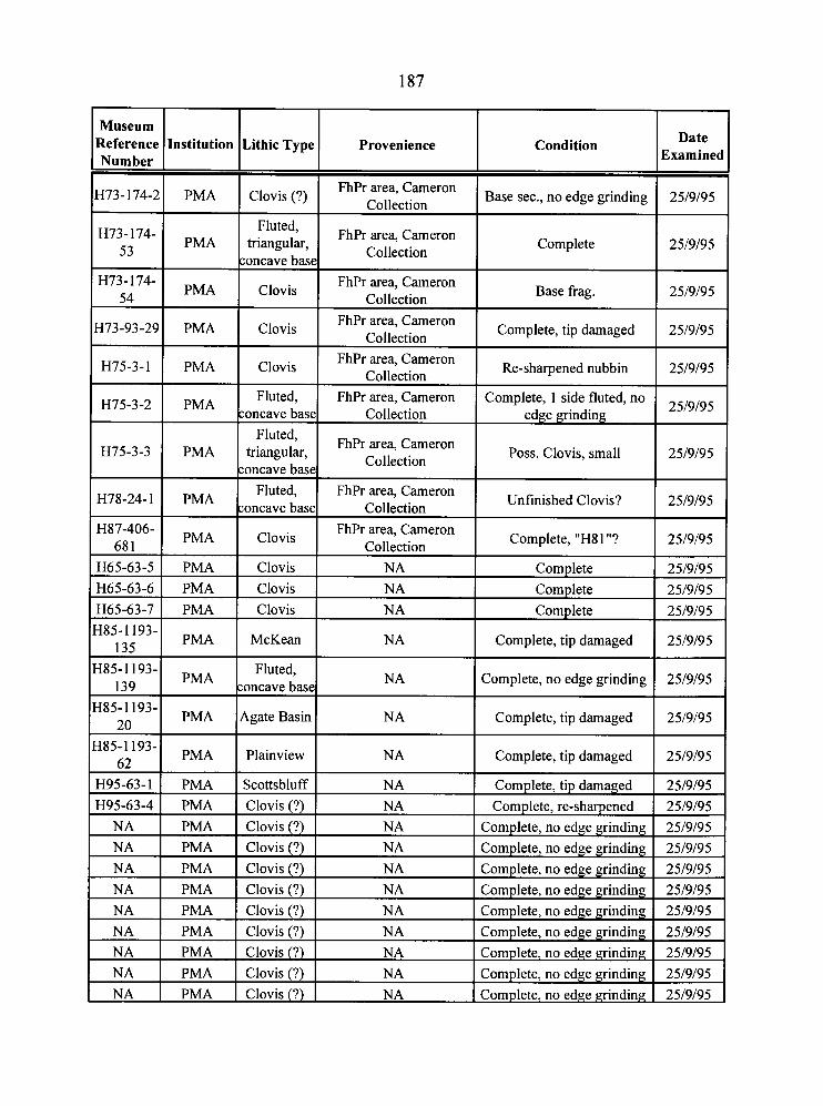
Museum Reference Number
H73- 174-2
H73-1 74- 53
H73-174- 54
H73-93-29
H75-3-1
H75-3-2
H75-3-3
H78-24-1
H87-406- 68 1
H65-63-5 H65-63-6 H65-63-7 H85-1193-
135 H85-1193-
139 H85-1 193-
20
Institution
PMA
PMA
PMA
PMA
PMA
PMA
PMA
PMA
PMA
H85-1193- 62
NA 1 PMA I Clovis (?) I NA I Complete, no edge grinding 1 25/9/95 1
PMA
PMA
PMA
PMA
H95-63-1 H95-63-4
NA I PMA I Clovis (?) I NA I Complete, no edge grinding 1 25/9/95 1
Lithic Type
Clovis (?)
Fluted, triangular,
soncave base
Clovis
Clovis
Clovis
Fluted, concave base
triangular, concave base
Fluted, concave base
Clovis
Clovis Clovis
1
PMA
Clovis
McKean
Fluted, soncave base
Agate Basin
PMA PMA
Provenience
FhPr area, Cameron Collection
FhPr area, Cameron Collection
FhPr area, Cameron Collection
FhPr area, Cameron Collection
FhPr area, Cameron Collection
FhPr area, Cameron Collection
FhPr area, Cameron Collection
FhPr area, Cameron Collection
FhPr area, Cameron Collection
NA
NA
Plainview
NA
NA NA
NA
NA
NA
NA
Scottsbluff Clovis (?)
Condition
Base sec., no edge grinding
Complete
Base frag.
Complete, tip damaged
Re-sharpened nubbin
Complete, 1 side fluted, no edge grinding
Poss. Clovis, small
Unfinished Clovis?
Complete, "H8 1 "?
Complete
Complete
NA
PMA PMA PMA
Date Examined
25/9/95
25/9/95
25/9/95
25/9/95
25/9/95
25/9/95
25/9/95
25/9/95
25/9/95
25/9/95 25/9/95
Complete
Complete, tip damaged
Complete, no edge grinding
Complete, tip damaged
NA NA
25/9/95
25/9/95
25/9/95
25/9/95
Complete, tip damaged
Clovis (?)
Clovis (?)
Clovis (?)
25/9/95
Complete, tip damaged Complete, re-sharpened
25/9/95 25/9/95
NA NA NA
Complete, no edge grind in^
Complete, no edge grinding Complete, no edge grinding
25/9/95 25/9/95 25/9/95
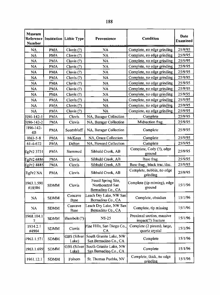
Condition Date
Examined
Museum Reference I Institution Lithic Type Provenience Number
NA PMA Clovis (?)
Clovis (?)
Clovis (?)
Clovis (?) PMA
NA I PMA Clovis (?)
NA 1 PMA Clovis (?)
Clovis (?)
Clovis (?)
NA I PMA Clovis (?)
NA I PMA Clovis (?)
Clovis (?)
Clovis (?)
Clovis Clovis
Scottsbluff
NA NA, Barager Collection
NA, Barager Collection
NA, Barager Collection Complete 25/9/95
Com~lete 25/9/95 McKean Dalton
NA. Grace Collection
NA, Howard Collection
Sibbald Creek, AB Stemmed
Clovis Clovis
Sibbald Creek, AB Sibbald Creek, AB
Sibbald Creek, AB
ZgPr2 68861 PMA
Complete, nubbin, no edge grinding
25/9/95 Clovis
Fossil Spring Site, Northcentral San
Bemadino Co., CA
Complete (tip missing), edge ground 1 15/1/96 Clovis
Concave Base
Concave Base
Humbolt (?)
Leach Dry Lake, NW San Complete, obsidian 15/1/96
Bernadine Co., CA
NA I SDMM Leach Dry Lake, NW San
Bemadino Co., CA
NS-25
San Bemadino Co.. CA
Proximal section, massive impact(?) fracture
15/1/96
Complete (2 pieces), large, quartz crystal
15/1/96
GBS (Silver
GBS (Silver
Folsom
Complete 15/1/96
Complete, thick, no edge 15/1/96
South Granite Lake, NW
St. Thomas Pueblo, NV
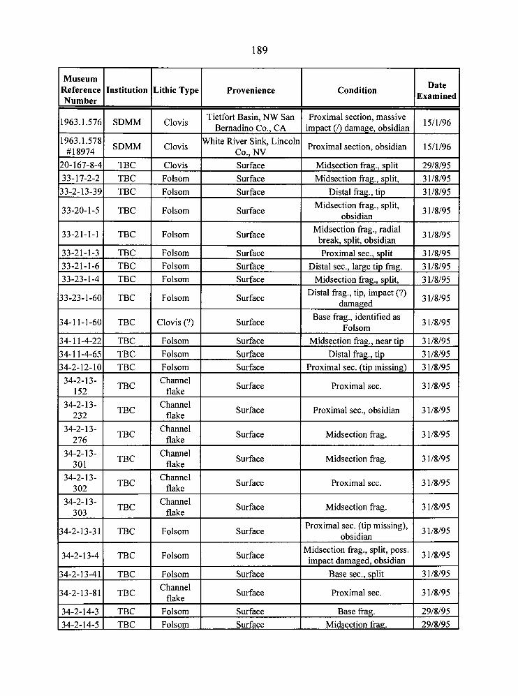
Museum Reference Institution Lithic Type Provenience - * Number I 963.1 .576 SDMM Clovis Tietfort Basin, NW San
Bernadine Co., CA 963.1.578) SDMM I White River Sink, Lincolr # 18974 C1OVis I Co.. NV
Clovis Surface Folsom Surface
Folsom Surface
Folsom Surface
33-21-1-1 TBC Folsom Surface
33-21-1-3 1 TBC I Folsom I Surface 33-21-1-6 TBC Folsom Surface 33-23-1-4 TBC Folsom Surface
3-23-1-60 TBC Folsom Surface
4-11-1-601 ZE3: 1 Clovis (?) 1 Surface
4- 1 1-4-22 Folsom Surface 4- 1 1-4-65 TBC Folsom Surface 4-2-12-10 TBC Folsom Surface 34-2-13-
TBC Channel
152 flake Surface
34-2-13- 1 TBC I C k r l I 232 Surface
34-2-13- TBC
Channel 276 flake
Surface
34-2-13- TBC
Channel 301 flake
Surface
34-2-13- TBC
Channel 302 flake
Surface
34-2-13- TBC
Channel 303 flake
Surface
4-2-13-3 1 TBC Folsom Surface
14-2-13-4 1 TBC ( Folsom I Surface I I I
4-2-13-41 1 TBC I Folsom I Surface
4-2-13-81 TBC Channel
flake Surface
34-2-14-3 1 TBC I Folsom I Surface 34-2-14-5 1 TBC I Folsom I Surface
Condition Date Examined
Proximal section, massive 15/1/96
Midsection frag., split 1 29/8/95
Midsection fiag., split, 3 1/8/95 Distal frag., tip 3 1/8/95
Midsection frag., split, obsidian
3 1/8/95
Midsection frag., radial 3 1/8/95
Proximal sec.. s ~ l i t 3 1/8/95
Distal sec., large tip frag. 1 31/8/95 Midsection frag., split, 1 3 1/8/95
Distal frag., tip, impact (?) damaged
3 1/8/95
Base frag., identified as Folsom
3 1/8/95
Proximal sec. 3 1/8/95
Proximal see., obsidian 1 31/8/95
3 1/8/95
Midsection frag. 3 1/8/95
Proximal sec. 3 1/8/95
Midsection frag. 3 1/8/95
Proximal sec. (tip missing), obsidian
3 1/8/95
Midsection frag., split, poss. impact damaged, obsidian
3 1/8/95
Base sec., s lit 3 1/8/95
Proximal sec. 3 1 18/95 . Base frag. 1 29/8/95
Midsection frag. 1 29/8/95
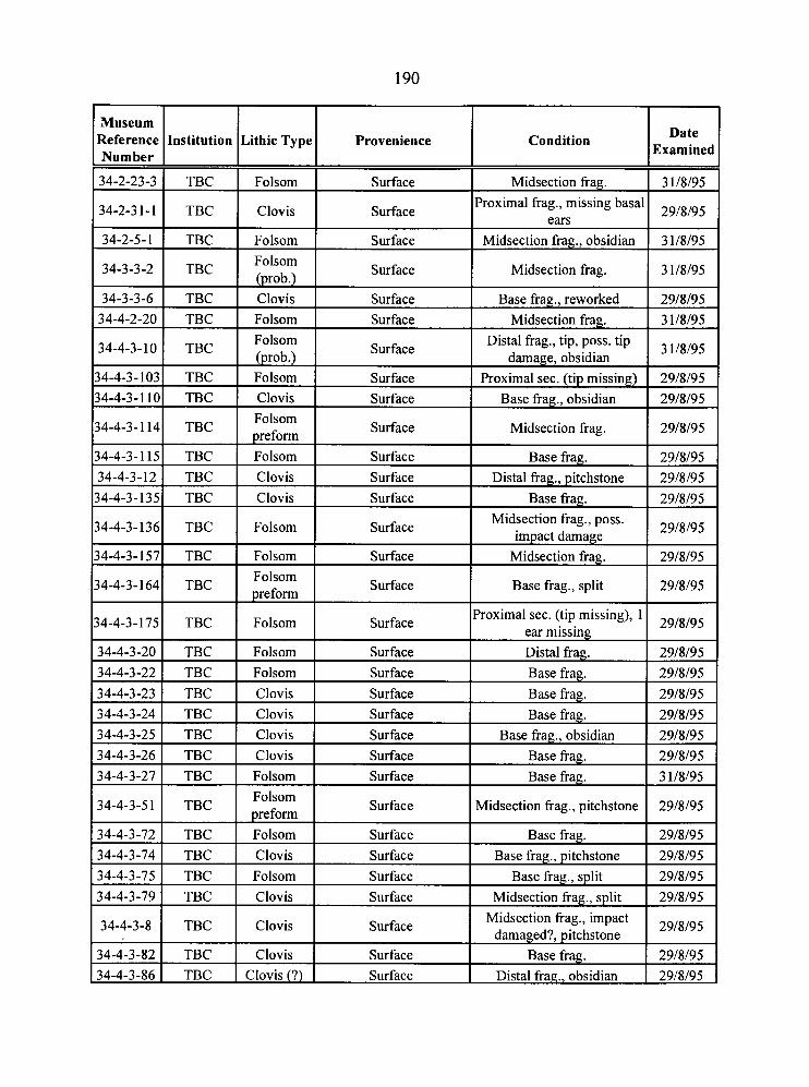
34-2-23-3 1 TBC I Folsom I Surface I Midsection frag. 1 3 1/8/95 1
Museum Reference Number
34-2-5-1 1 TBC I Folsom I Surface I Midsection frag., obsidian 1 3 1/8/95 1
Institution
34-2-3 1 - 1
Lithic Type
TBC
34-3-3-2
34-3-3-6
34-4-2-20
134-4-3-1351 TBC I Clovis I Surface 1 Base frag. 1 29/8/95 1
Provenience
Clovis
1
TBC
34-4-3-10
34-4-3- 103
34-4-3- 1 10
34-4-3- 1 14
34-4-3- 1 15
34-4-3-12
TBC TBC
Condition
Surface
Folsom (prob.)
TBC
TBC TBC
TBC
TBC TBC
34-4-3-136
34-4-3-157
Date Examined
Clovis Folsom
34-4-3-164
Proximal frag., missing basal ears
Surface
Folsom (prob.) Folsom Clovis Folsom preform Folsom Clovis
TBC
TBC
34-4-3- 175
29/8/95
Surface Surface
TBC
34-4-3-20
34-4-3-22
34-4-3-23
134-4-3-27 1 TBC I Folsom I Surface 1 Base frag. 1 31/8/95 1
Midsection frag.
Surface
Surface Surface
Surface
Surface Surface
Folsom
Folsom
TBC
34-4-3-24
34-4-3-25
34-4-3-26
3 1/8/95
Base fiag., reworked Midsection frag.
Folsom preform
TBC TBC TBC
29/8/95
3 1/8/95
Distal frag., tip, poss. tip damage, obsidian
Proximal sec. (tip missing) Base frag., obsidian
Midsection frag.
Base frag.
Distal frag., pitchstone
Surface
Surface
Folsom
TBC TBC TBC
34-4-3-5 1
34-4-3-72
3 1/8/95
29/8/95
29/8/95
29/8/95
29/8/95
29/8/95
Surface
Folsom Folsom Clovis
34-4-3-74
34-4-3-75
34-4-3-79
Midsection frag., poss. impact damage
Midsection frag.
Surface
Clovis Clovis Clovis
TBC
TBC
34-4-3-8
29/8/95
29/8/95
Base frag., split
Surface Surface Surface
TBC TBC TBC
34-4-3-82
34-4-3-86
29/8/95
Proximal sec. (tip missing), 1 ear missing
Surface Surface Surface
Folsom preform Folsom
TBC
29/8/95
Distal fiag. Base frag.
Base fiag.
Clovis Folsom Clovis
TBC TBC
29/8/95
29/8/95
29/8/95
Base frag. Base frag., obsidian
Base frag.
Surface
Surface
Clovis
29/8/95
29/8/95
29/8/95
Surface Surface Surface
Clovis Clovis (?)
Midsection frag., pitchstone
Base frag.
Surface
29/8/95
29/8/95
Base frag., pitchstone Base fiag., split
Midsection frag., split
Surface Surface
29/8/95
29/8/95
29/8/95
Midsection frag., impact damaged?, pitchstone 29/8/95
Base frag. Distal frag., obsidian
29/8/95
29/8/95
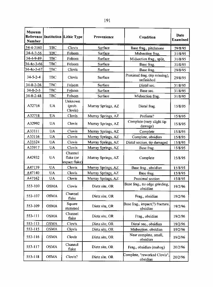
Museum Reference Number
34-4-3 160 34-4-7-56 34-4-9-89 34-4c-3-66
34-4c-3-67
Institution
34-5-2-4
34-8-2-26
TBC
TBC TBC TBC
TBC
34-8-2-3 34-8-2-48
A327 16
A327 18
Lithic Type
TBC
TBC
A42932
A47139 A47 140 A47 162
Clovis Folsom
Folsom Folsom
Clovis
TBC TBC
UA
UA
553-100
553-107
553-109
553-111
Provenience
Clovis
Folsom
UA
UA
UA UA
553-113
553-115
553-116
553-117
553-1 18
Surface Surface Surface
Surface Surface
Folsom Folsom
Unknown (prob.
Clovis) Clovis
OSMA
OSMA
OSMA
OSMA
Condition
Surface
Surface
Channel flake (or
impact flake) Clovis Clovis
Clovis
OSMA OSMA
OSMA
OSMA
OSMA
Date Examined
Base frag., pitchstone Midsection frag.
Midsection frag., split, Base frag. Base frag.
Surface
Surface
Murray Springs, AZ
Murray Springs, AZ
Clovis
Channel flake
Square stemmed Channel
flake
29/8/95
3 1/8/95 ,
3 1/8/95 3 1/8/95 29/8/95
Proximal frag. (tip missing), unfinished Distal sec.
Murray Springs, AZ
Murray Springs, AZ
Murray Springs, AZ Murray Springs, AZ
Clovis
Clovis
Clovis
Channel flake
Clovis?
29/8/95
3 1/8/95 Base sec.
Midsection frag.
Distal frag.
Preform?
Dietz site, OR
Dietz site, OR
Dietz site, OR
Dietz site, OR
3 1/8/95 3 1/8/95
15/8/95
15/8/95
Complete
Base frag., obsidian Base frag.
Proximal section
Dietz site, OR
Dietz site, OR
Dietz site, OR
Dietz site, OR
Dietz site, OR
15/8/95
15/8/95 15/8/95
15/8/95 Base frag., no edge grinding,
obsidian
Frag., obsidian
Base frag., impact(?) fracture, obsidian
Frag., obsidian
19/2/96
19/2/96
19/2/96
19/2/96
Distal sec., obsidian
Midsection, obsidian Near complete, small,
obsidian
Frag., obsidian (mahog)
Zomplete, "reworked Clovis", obsidian
19/2/96
19/2/96
19/2/96
2012196
2012196
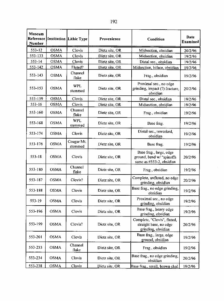
Museum Reference Institution Number I .ithie Type I Provenience Condition
Clovis Dietz site. OR
Midsection, obsidian Midsection, obsidian Distal sec., obsidian
Midsection, biface, obsidian
553-14 1 OSMA 553-142 I OSMA Fluted? I Dietz site, OR
Channel flake
I Dietz site, OR Frag., obsidian
Proximal sec., no edge yinding, impact (?) fracture
obsidian
WPL stemmed
Clovis Clovis
Channel flake
Distal sec., obsidian Midsection, obsidian
Dietz site, OR
Dietz site, OR Dietz site, OR
Dietz site, OR 553-160 OSMA
553-168 OSMA
553-174 OSMA * Frag., obsidian
Dietz site, OR Base frag.
Distal sec., reworked, obsidian
Base frag.
Clovis I Dietz site, OR
553-176 1 OSMA Zougar Mt.
Dietz site, OR
Base frag., large, edge ground, bend w/ "spinoffs same as #553-2, obsidian
553-18 C1Ovis I Dietz site, OR OSMA
Channel Dietz site, OR
flake I Frag., obsidian
:omplete, unfluted, no edge grinding, obsidian
lase frag., no edge grinding, obsidian
Proximal sec., no edge grinding, obsidian
Base frag., heavy edge grinding, obsidian
Complete, "Clovis", fluted, straight base, no edge
grinding, obsidian Base frag., large, edge
ground, obsidian
Frag., obsidian
Clovis? Dietz site, OR
Clovis Dietz site, OR 553-188 1 OSMA
Clovis Dietz site, OR
Clovis Dietz site, OR
553-199 OSMA Clovis?
I Dietz site, OR flake
Dietz site, OR
Clovis
Clovis Dietz site, OR
Clovis
Dietz site, OR
lase frag., no edge grinding, obsidian
553-238 1 OSMA ase frag., small, brown chal.
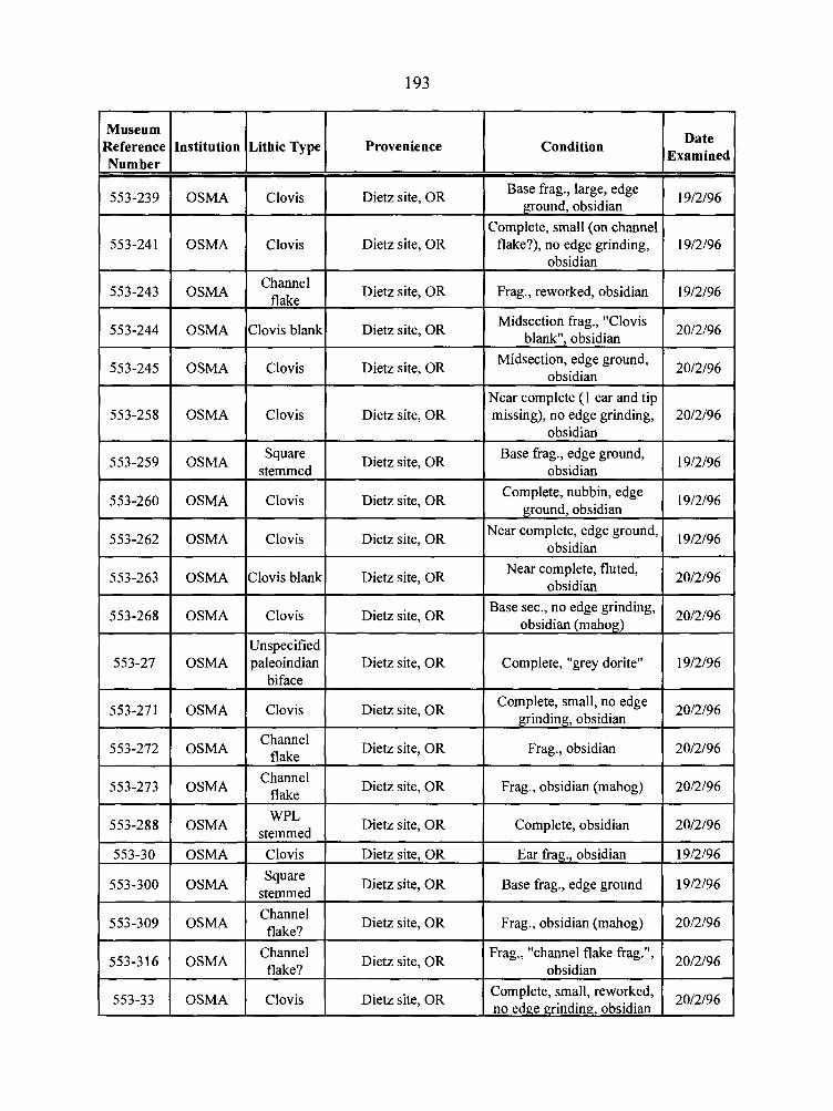
Museum
Number I I
553-239 1 OSMA
553-258 OSMA I
553-288 1 OSMA
553-33 1 OSMA
1 Clovis 1 Dietz site, OR Base frag., large, edge 1 mound. obsidian
I 19/2/96 I
I
Lithic Type I
I Complete, small (on channel I clovis Dietz site, OR 1 flake?), no edge grinding, I 19/2/96 I
Provenience
I Channel flake
Clovis blank
Clovis
Condition
Clovis
Date Examined
Dietz site, OR
Dietz site, OR
Dietz site, OR
Square stemmed
Dietz site, OR
Clovis
Frag., reworked, obsidian
Midsection frag., "Clovis blank", obsidian
Midsection, edge ground, obsidian
Near complete (1 ear and tip missing), no edge grinding,
obsidian
Dietz site, OR
Clovis
19/2/96
2012196
2012196
Dietz site, OR
Clovis blank
Unspecified paleoindian I Dietz site, OR I Complete, "grey dorite" ( 1912196 1
Base frag., edge ground, obsidian
Dietz site, OR
Clovis
1912196
Complete, nubbin, edge ground, obsidian
Dietz site, OR
19/2/96
Near complete, edge ground, obsidian
Dietz site, OR
Clovis
I Dietz site, OR I flake Frag., obsidian (mahog) 1 2012196 I
19/2/96
Near complete, fluted, obsidian
Channel flake
2012196
Base sec., no edge grinding, obsidian (mahog)
Dietz site, OR
2012196
Dietz site, OR
WPL stemmed Clovis
Square stemmed Channel flake?
Channel flake?
Complete, small, no edge grinding, obsidian
Clovis
20/2/96
Frag., obsidian
Dietz site, OR
Dietz site, OR
Dietz site, OR
Dietz site, OR
Dietz site, OR
2012196
Dietz site, OR
Complete, obsidian
Ear frag., obsidian
Base frag., edge ground
Frag., obsidian (mahog)
Frag., "channel flake frag.", obsidian
2012196
19/2/96
19/2/96
2012196
2012196
Complete, small, reworked, no edge grinding. obsidian
2012196
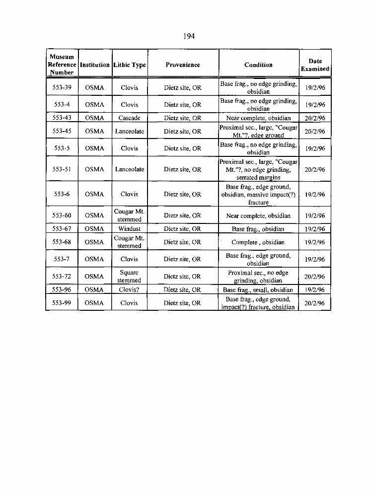
Museum Reference Number
553-39
553-4
553-43
553-45
553-5
553-5 1
553-6
553-60
553-67
553-68
553-7
553-72
553-96
553-99
Institution
OSMA
OSMA
OSMA
OSMA
OSMA
OSMA
OSMA
OSMA
OSMA
OSMA
OSMA
OSMA
OSMA
OSMA
Lithic Type
Clovis
Clovis
Cascade
Lanceolate
Clovis
Lanceolate
Clovis
Cougar Mt. stemmed
Windust Cougar Mt.
stemmed
Clovis
Square stemmed Clovis?
Clovis
Provenience
Dietz site, OR
Dietz site, OR
Dietz site, OR
Dietz site, OR
Dietz site, OR
Dietz site, OR
Dietz site, OR
Dietz site, OR
Dietz site, OR
Dietz site, OR
Dietz site, OR
Dietz site, OR
Dietz site, OR
site' OR
Condition
Base frag., no edge grinding, obsidian
Base frag., no edge grinding, obsidian
Near complete, obsidian Proximal sec., large, "Cougar
Mt."?, edge ground Base frag., no edge grinding,
obsidian
Proximal sec., large, "Cougar Mt."?, no edge grinding,
serrated margins Base frag., edge ground,
obsidian, massive impact(?) fracture
Near complete, obsidian
Base fiag., obsidian
Complete , obsidian
Base frag., edge ground, obsidian
Proximal sec., no edge grinding, obsidian
Base frag., small, obsidian Base frag., edge ground,
impact(?) fracture. obsidian
Date Examined
19/2/96
19/2/96
2012196
2012196
19/2/96
2012196
19/2/96
19/2/96
19/2/96
19/2/96
19/2/96
2012196
19/2/96
2012196