Embed Size (px)
Citation preview
Proceedings of the Annual Stability Conference
Structural Stability Research Council St. Louis, Missouri, April 16-20, 2013
The Overall Interaction Concept: an Alternative Approach to the Stability and Resistance of Steel Sections and Members
N. Boissonnade1, J. Nseir2, E. Saloumi3
Abstract
The Overall Interaction Concept (O.I.C.) stands as a new design approach that aims at a straightforward design check of the stability and resistance of steel members. It was developed in response to the expansion of high strength steel products, where instability has more influence and deserves specific attention, especially at the cross-sectional level.
Based on the use of a generalized relative slenderness and so-called interaction curves, it applies to both open and tubular cross-sections, further includes potential non-linear material behavior (beneficial strain hardening effects, e.g. stainless steel or cold formed hollow profiles) and covers combined loading cases. In addition, it can be applied in a similar manner to cross-section or to member verifications.
The present paper first describes the bases and features of the O.I.C.; detailed information is given on its application to either sections or members, to combined loading situations, and to materials exhibiting a high degree of non-linearity. Then, its accuracy and applicability is tested against many experimental results and FE simulations, and the potential for the O.I.C. to become an accurate and effective approach for practical design is demonstrated.
Provided additional complementary developments, the O.I.C. may appear as a powerful alternative to the current design methodologies, and serve as a basis for the next generation of standards and practical tools, especially in the frame of an increasing use of high steel grades.
1. Introduction
Present paper concerns the effective and practical design of steel members. More precisely, a recently developed alternative approach to the stability and resistance of steel members, the Overall Interaction Concept (O.I.C.), is presented and detailed here. Applicable to the design of both sections and members, it has been developed mainly to i) improve actual design practice, ii) increase accuracy, and iii) advance simplicity and consistency.
The investigations have also been driven by the current trend to increase the standard available steel grade, and directed towards usual steel grades and high strength steels (i.e. yield
1 Professor, University of Applied Sciences of Western Switzerland, <[email protected]> 2 Graduate Student, University of Applied Sciences of Western Switzerland, <[email protected]> 3 Graduate Student, University of Applied Sciences of Western Switzerland, <[email protected]>
48
stress > 65 ksi). For such steel grades, the influence of instability effects is more pronounced, and affects usual design practices. In particular, sections made of high strength steel fall into the slender range, which implies long and fastidious calculations for the designer; further, as all fibers of the cross-section cannot reach the yield stress at the peak load, the economic interest of resorting to such grades is somewhat lost. Accordingly, the need for adapted and efficient but simple approaches is actually getting more and more pronounced.
Presently, it shall be noted that the most recent design codes handle the influence of instabilities in many different ways. In a non-exhaustive manner, it is possible to refer to the approaches of AISC/LRFD recommendations (AISC 2005), Eurocode 3 (CEN 2005), the British Standards (BSI 2000), the Australian code (SA 1998)… As an example, one may cite the many sets of design formulae for beam-columns, relying on as many different approaches as the Merchant-Rankine formula (Merchant 1964), the Ayrton-Perry proposal (Maquoi 1978), the German approach (DIN 1990), or the more recent rules proposed in Eurocode 3 (Boissonnade 2006)4. For what concerns local buckling, most of these codes rely on the effective width concept, and propose so-called b / t limit ratios that each of the section’s wall should fulfill to be considered as non-affected by early local buckling. Besides, alternatives recently developed based on the use of more sophisticated tools (Schafer 2006) or on a continuous relationship between strains and plate slenderness (Gardner 2008) have been suggested.
From a practical point of view, these codes and methods however still suffer from a series of problems and inadequacies. Amongst them, the handling of local buckling may appear as the one causing most problems; it is indeed usual to select the resistance formulae to be used by the designer in accordance with the proneness of the cross-sections to suffer from early local buckling effects: the earlier the occurrence of local buckling is expected to occur, the more restricted the design rules become.
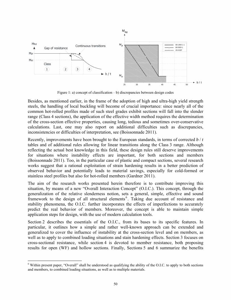
In Eurocode 3 for example, this is accounted for through an additional step prior to the verification process that consists in the classification of the cross-section. According to the Class of the section5, different sets of formulae are to be used for the design checks of both sections and members, i.e. plastic or elastic equations. First of all, it has been shown (Semi-Comp 2007) that several values of the b / t limit ratios of Eurocode 3 are often misleading, further to suffering from a lack of mechanical background. Moreover, this concept of classes, as it is defined – discrete and artificial –, generates a gap of resistance at the Class 2-3 border, which is mechanically meaningless and unacceptable (see Fig. 1a).
Fig. 1b also plots an example of a comparison between recommended b / t flange limits according to various standards for cold-formed hollow sections under major-axis bending moment. The observed discrepancies are so important that several b / t values seem questionable, to say the least. Another important limitation embedded with the b / t limit ratios commonly found in standards lies in the assumed “ideal support conditions” of the various plates comprised within the whole section, since the interaction between elements is indeed usually disregarded (Seif 2010), each being presumed to behave discretely.
4 The practical design of steel beam-columns remains one of the most challenging problems for engineers, and numerous research works have been led on this specific topic, see for example Massonnet 1976. To the authors’ knowledge, a fully satisfactory design procedure is not available yet. 5 The class of the entire section is governed and defined by the class of its worst element: in Eurocode 3, class 1 stands for “plastic”, 2 for “compact”, 3 for “semi-compact” and 4 for “slender”.
49
25 30 35 40 45 50
EN 1993-1-1
BS 5950-1
AS 4100*
b / t
Mel
Mpl
MRd
Figure 1: a) concept of classification – b) discrepancies between design codes
Besides, as mentioned earlier, in the frame of the adoption of high and ultra-high yield strength steels, the handling of local buckling will become of crucial importance: since nearly all of the common hot-rolled profiles made of such steel grades exhibit sections will fall into the slender range (Class 4 sections), the application of the effective width method requires the determination of the cross-section effective properties, causing long, tedious and sometimes over-conservative calculations. Last, one may also report on additional difficulties such as discrepancies, inconsistencies or difficulties of interpretation, see (Boissonnade 2011).
Recently, improvements have been brought to the European standards, in terms of corrected b / t tables and of additional rules allowing for linear transitions along the Class 3 range. Although reflecting the actual best knowledge in this field, these design rules still deserve improvements for situations where instability effects are important, for both sections and members (Boissonnade 2011). Too, in the particular case of plastic and compact sections, several research works suggest that a rational exploitation of strain hardening results in a better prediction of observed behavior and potentially leads to material savings, especially for cold-formed or stainless steel profiles but also for hot-rolled members (Gardner 2011).
The aim of the research works presented herein therefore is to contribute improving this situation, by means of a new “Overall Interaction Concept” (O.I.C.). This concept, through the generalization of the relative slenderness notion, sets a general, simple, effective and sound framework to the design of all structural elements6 . Taking due account of resistance and stability phenomena, the O.I.C. further incorporates the effects of imperfections to accurately predict the real behavior of members. Moreover, the concept is able to maintain simple application steps for design, with the use of modern calculation tools.
Section 2 describes the essentials of the O.I.C., from its bases to its specific features. In particular, it outlines how a simple and rather well-known approach can be extended and generalized to cover the influence of instability at the cross-section level and on members, as well as to apply to combined loading situations and stain hardening effects. Section 3 focuses on cross-sectional resistance, while section 4 is devoted to member resistance, both proposing results for open (WF) and hollow sections. Finally, Sections 5 and 6 summarize the benefits
6 Within present paper, “Overall” shall be understood as qualifying the ability of the O.I.C. to apply to both sections and members, to combined loading situations, as well as to multiple materials.
50
brought by the use of the O.I.C. in practical design, as well as actual and future developments, respectively.
2. Mechanical bases and background of the O.I.C.
2.1 General concept
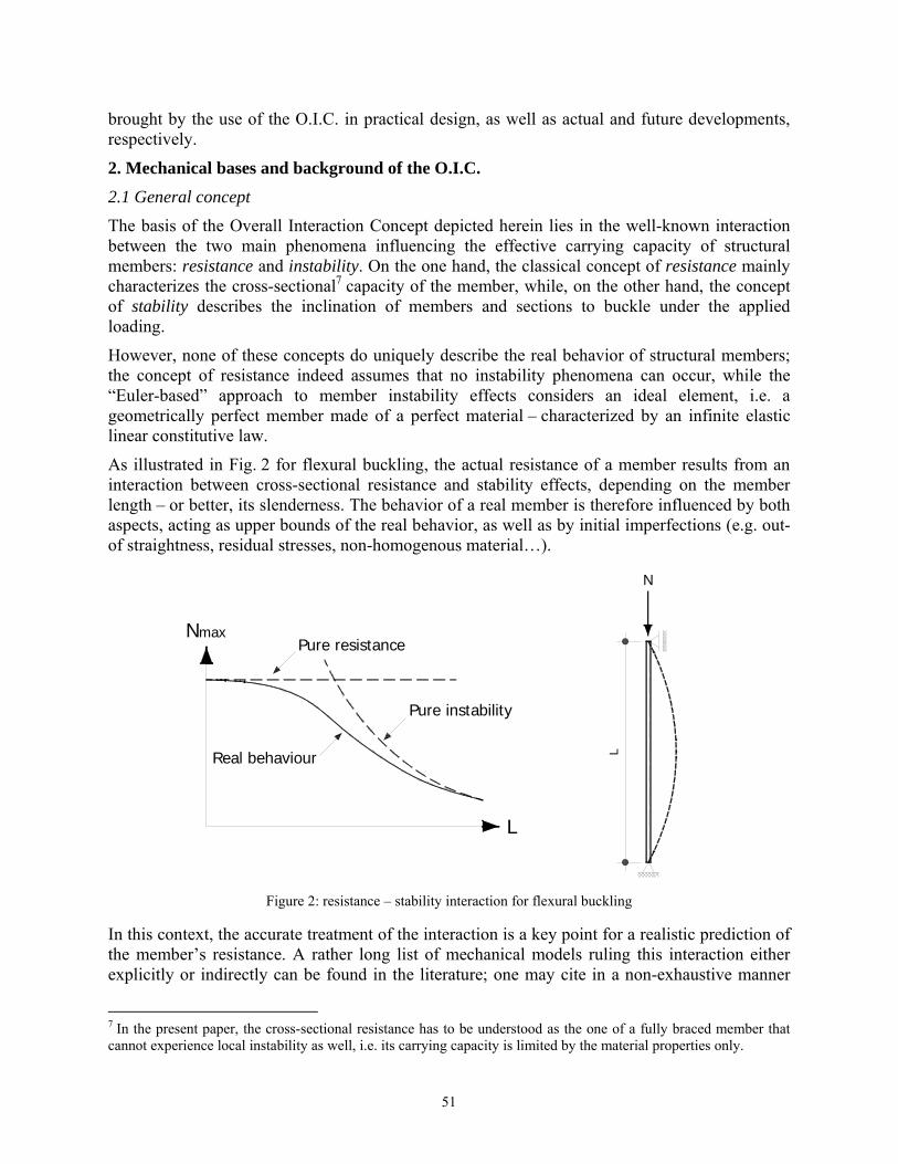
The basis of the Overall Interaction Concept depicted herein lies in the well-known interaction between the two main phenomena influencing the effective carrying capacity of structural members: resistance and instability. On the one hand, the classical concept of resistance mainly characterizes the cross-sectional7 capacity of the member, while, on the other hand, the concept of stability describes the inclination of members and sections to buckle under the applied loading.
However, none of these concepts do uniquely describe the real behavior of structural members; the concept of resistance indeed assumes that no instability phenomena can occur, while the “Euler-based” approach to member instability effects considers an ideal element, i.e. a geometrically perfect member made of a perfect material – characterized by an infinite elastic linear constitutive law.
As illustrated in Fig. 2 for flexural buckling, the actual resistance of a member results from an interaction between cross-sectional resistance and stability effects, depending on the member length – or better, its slenderness. The behavior of a real member is therefore influenced by both aspects, acting as upper bounds of the real behavior, as well as by initial imperfections (e.g. out-of straightness, residual stresses, non-homogenous material…).
Nmax
L
Pure resistance
Pure instability
Real behaviour
L
N
Figure 2: resistance – stability interaction for flexural buckling
In this context, the accurate treatment of the interaction is a key point for a realistic prediction of the member’s resistance. A rather long list of mechanical models ruling this interaction either explicitly or indirectly can be found in the literature; one may cite in a non-exhaustive manner
7 In the present paper, the cross-sectional resistance has to be understood as the one of a fully braced member that cannot experience local instability as well, i.e. its carrying capacity is limited by the material properties only.
51
the works of Ayrton-Perry (Maquoi 1978), the Direct Strength Method (Schafer 2006), the Effective Width Concept (Johansson 2007)…
Surprisingly, no recognized general theoretical background has been established to organize and unify the handling of this crucial interaction in a global way. Even if all of the above-referenced developments deal with the resistance-stability interaction, they are built in totally different ways, and a lack of a general and global basis can be pointed out. Furthermore, the way this interaction is dealt with may be highly complex in some situations, such as for slender sections for example, where fastidious iterative procedures are usually required.
Almost no attempts have been made to overcome this unsatisfactory situation in a global way. However, recent developments (Boissonnade 2011, STSS 2012, Li 2012) have snatched a glimpse that such an ambitious general approach can fill this fundamental gap of knowledge: the so-called “Overall Interaction Concept”. Despite the formal simplicity of the concept, the potential of the O.I.C. is such that all structural members, whatever the material, could be treated with an identical general, global, accurate, simple and sound-based background.
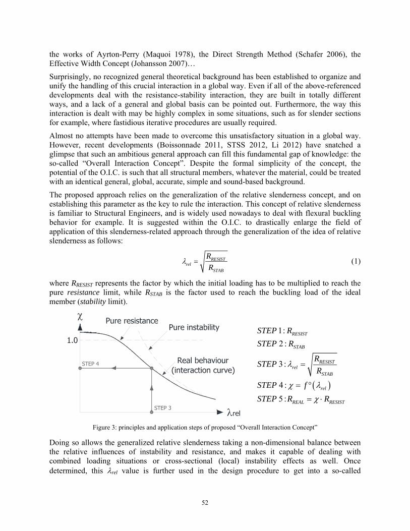
The proposed approach relies on the generalization of the relative slenderness concept, and on establishing this parameter as the key to rule the interaction. This concept of relative slenderness is familiar to Structural Engineers, and is widely used nowadays to deal with flexural buckling behavior for example. It is suggested within the O.I.C. to drastically enlarge the field of application of this slenderness-related approach through the generalization of the idea of relative slenderness as follows:
RESISTrel
STAB
R
Rl = (1)
where RRESIST represents the factor by which the initial loading has to be multiplied to reach the pure resistance limit, while RSTAB is the factor used to reach the buckling load of the ideal member (stability limit).
1:
2 :
3 :
4 :
5 :
RESIST
STAB
RESISTrel
STAB
rel
REAL RESIST
STEP R
STEP R
RSTEP
R
STEP f
STEP R R
Figure 3: principles and application steps of proposed “Overall Interaction Concept”
Doing so allows the generalized relative slenderness taking a non-dimensional balance between the relative influences of instability and resistance, and makes it capable of dealing with combined loading situations or cross-sectional (local) instability effects as well. Once determined, this rel value is further used in the design procedure to get into a so-called
52
“interaction curve” (also sometimes referred to as “buckling curve”) and leads to the determination of a “” value (see Fig. 3). This value (analogous to the one used in Eurocode 3), which may also be called “reduction factor”, represents the penalty due to instability effects on the pure resistant behavior, and can obviously only be lower than 1.0. Then, the final resistance is evaluated as . RRESIST; Fig. 3 further illustrates the proposed approach and its application steps8.
This rather simple procedure can be applied to many situations within structural engineering (e.g. member buckling, cross-sectional resistance…), regardless of the material behavior, and be a general approach to each design situation where instability affects the resistance. The following paragraphs details how this general approach may apply to slender cross-sections (i.e. prone to local buckling) and to combined loading situations.
2.2 Application to cross-sectional behavior
When applied to the particular case of cross-sectional resistance, the O.I.C. approach remains as explained in the previous paragraph, except that RSTAB relates to cross-sectional instability, i.e. local or distortional buckling.
Obviously, RRESIST remains unchanged, and, usually, the critical load factor RSTAB is calculated by means of plate linear buckling theory, and so-called critical stresses cr, determined for each of the cross-section walls, can be evaluated; they depend on the various edge conditions and on the distribution of stresses of the considered wall. The weakest wall is then identified as the one with the minimum cr value, and RSTAB is simply set as the ratio between cr and the actual stress on the considered wall.
However, as in many design codes, usual approximations for cr values assume simple (and somewhat ideal) support conditions for the various walls of the section: simply supported webs, and clamped-free outstand elements. Doing so disregards potential significant resistance reserves that may be reached in considering the cross-section as a whole, i.e. accounting for beneficial restraints brought by adjacent walls.
Nowadays, numerical solutions exist for such an advanced calculation of RSTAB, such as software CUFSM (Li 2010) or GBTUL (Bebiano 2008) for example, which allow for a more accurate and straightforward prediction of elastic cross-section stability. Accordingly, such numerical calculations of RSTAB greatly differ from those obtained from approximate formulae, and so do the corresponding rel values and associated interaction curves.
Besides the opportunity to resort to these numerical tools, it shall be recalled that the proposed O.I.C. approach allows for a direct determination of the cross-sectional resistance, regardless of the section’s shape. Further, no classification of the cross-section is needed (unlike in the AISC or European standards for example), and the case of slender sections is accounted for in a quite simple way, without the usual tedious effective properties calculations yielded by the usual effective width method; this is expected to become of increasing importance in the frame of the development of high strength steels.
Recent developments in the field of cold-formed sections (Direct Strength Method, see Schafer 2006) and on stainless steel (Continuous Strength Method, Gardner 2008) may appear as equivalent or complementary proposals to the O.I.C., and several attempts into the behavior of 8 This procedure is currently the one used for flexural and lateral torsional buckling in many design codes.
53
hot-rolled steel sections have been made. To date, both the D.S.M. and the C.S.M. do not allow for combined loading situations yet, which is a feature the O.I.C. can afford rather simply, see next paragraph.
2.3 Extension to combined loading situations
The Overall Interaction Concept remains valid and applies whatever the loading acting on the considered member, with the same application steps. Indeed, as detailed in § 2.1, the proposed generalized slenderness is based on the calculation of “R-factors” (“load factors”) which, consequently, can be determined for any loading situation, i.e. for simple cases (pure compression or monoaxial bending) as well as for combined ones (biaxial bending with compression). Although their calculations do not raise particular difficulties for simple cases, it may appear much more delicate under biaxial bending and compression for example. RRESIST may however be relatively easily determined by means of either numerical tools or well-known plastic interaction formulae, and RSTAB can nowadays also be quite efficiently computed with software like CUFSM or GBTUL. The simplicity and ease of application of the O.I.C. are therefore preserved. This, for example, avoids resorting to complex member interaction formulae (see for example Eurocode 3, CEN 2005).
2.4 Non-linear material behavior
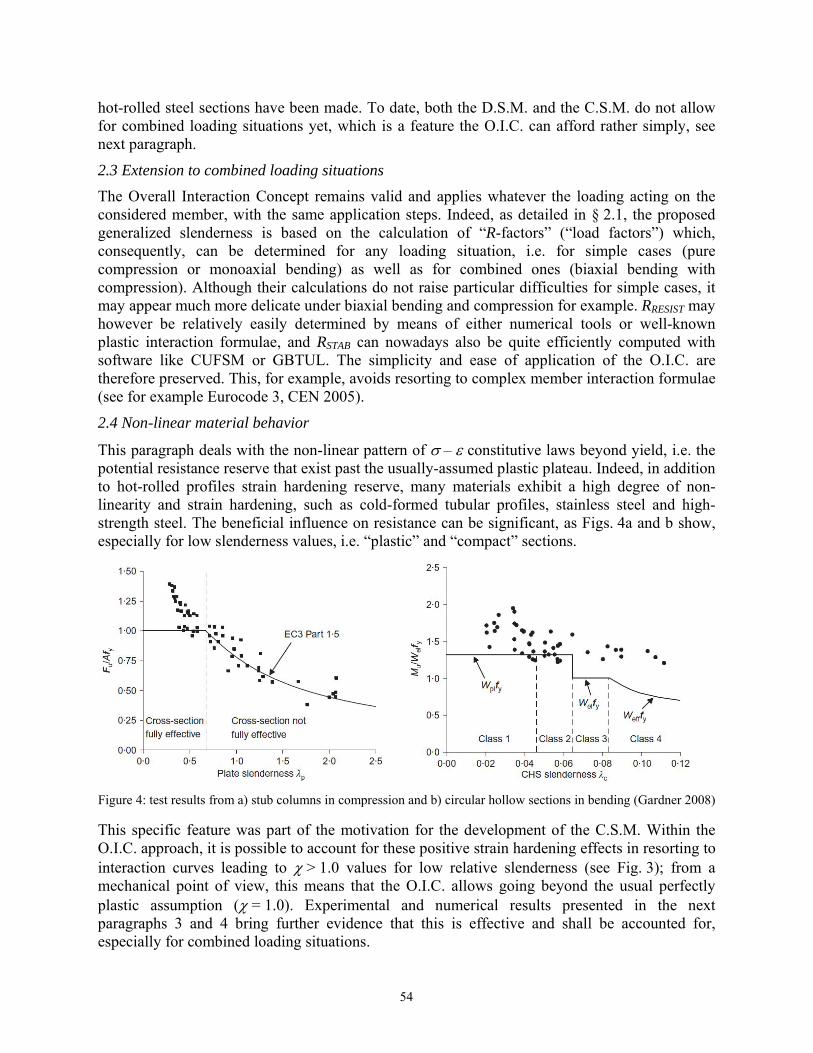
This paragraph deals with the non-linear pattern of – constitutive laws beyond yield, i.e. the potential resistance reserve that exist past the usually-assumed plastic plateau. Indeed, in addition to hot-rolled profiles strain hardening reserve, many materials exhibit a high degree of non-linearity and strain hardening, such as cold-formed tubular profiles, stainless steel and high-strength steel. The beneficial influence on resistance can be significant, as Figs. 4a and b show, especially for low slenderness values, i.e. “plastic” and “compact” sections.
Figure 4: test results from a) stub columns in compression and b) circular hollow sections in bending (Gardner 2008)
This specific feature was part of the motivation for the development of the C.S.M. Within the O.I.C. approach, it is possible to account for these positive strain hardening effects in resorting to interaction curves leading to > 1.0 values for low relative slenderness (see Fig. 3); from a mechanical point of view, this means that the O.I.C. allows going beyond the usual perfectly plastic assumption ( = 1.0). Experimental and numerical results presented in the next paragraphs 3 and 4 bring further evidence that this is effective and shall be accounted for, especially for combined loading situations.
54
3. Results for cross-sectional resistance
3.1 WF and I sections
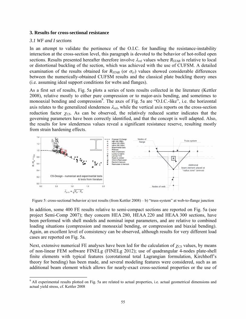
In an attempt to validate the pertinence of the O.I.C. for handling the resistance-instability interaction at the cross-section level, this paragraph is devoted to the behavior of hot-rolled open sections. Results presented hereafter therefore involve rel values where RSTAB is relative to local or distortional buckling of the section, which was achieved with the use of CUFSM. A detailed examination of the results obtained for RSTAB (or cr) values showed considerable differences between the numerically-obtained CUFSM results and the classical plate buckling theory ones (i.e. assuming ideal support conditions for webs and flanges).
As a first set of results, Fig. 5a plots a series of tests results collected in the literature (Kettler 2008), relative mostly to either pure compression or to major-axis bending, and sometimes to monoaxial bending and compression9. The axes of Fig. 5a are “O.I.C.-like”, i.e. the horizontal axis relates to the generalized slenderness rel, while the vertical axis reports on the cross-section reduction factor CS. As can be observed, the relatively reduced scatter indicates that the governing parameters have been correctly identified, and that the concept is well adapted. Also, the results for low slenderness values reveal a significant resistance reserve, resulting mostly from strain hardening effects.
Additionalbeam element placed at"radius zone" centroid
Nodes offlange
Nodes of web
Truss system
Figure 5: cross-sectional behavior a) test results (from Kettler 2008) – b) “truss-system” at web-to-flange junction
In addition, some 400 FE results relative to semi-compact sections are reported on Fig. 5a (see project Semi-Comp 2007); they concern HEA 280, HEAA 220 and HEAA 300 sections, have been performed with shell models and nominal input parameters, and are relative to combined loading situations (compression and monoaxial bending, or compression and biaxial bending). Again, an excellent level of consistency can be observed, although results for very different load cases are reported on Fig. 5a.
Next, extensive numerical FE analyses have been led for the calculation of CS values, by means of non-linear FEM software FINELg (FINELg 2012); use of quadrangular 4-nodes plate-shell finite elements with typical features (corotational total Lagrangian formulation, Kirchhoff’s theory for bending) has been made, and several modeling features were considered, such as an additional beam element which allows for nearly-exact cross-sectional properties or the use of
9 All experimental results plotted on Fig. 5a are related to actual properties, i.e. actual geometrical dimensions and actual yield stress, cf. Kettler 2008
55
linear constraints at the supports (see Boissonnade 2012 for more details). Moreover, a “truss system” was added to the models in the web-flange junction zone, in order to keep this region nearly rigid. This ensures local buckling waves to develop as realistically as possible and an accurate characterization of the onset of instability.
These FE-models being shown to be adequate (see Semi-Comp 2007), they have been extensively used within parametric studies. Two series of cross-sections were analyzed, namely the complete AISC W-sections database (203 sections) and all the European IPE, HEA, HEB and HEM sections (89 sections). The elastic-perfectly plastic with 2% strain hardening material law of Fig. 6b was adopted for all calculations, and suitable initial imperfections have been considered. The following set of parameters has been used in this first numerical study on open sections:
292 cross-section shapes (203 US + 89 European ones); 3 different steel grades: S235, S460, S690 for European profiles, and 36, 65 and 100 ksi
steel for US profiles (see Table 6a); The loading conditions have been varied as follows:
o A first case for sections under pure compression; o A second one for major-axis bending; o A first series of combined compression and biaxial bending situations, where an
initial load sequence increases axial compression up to 30% of the section’s capacity, followed by a second load sequence where compression is maintained constant and biaxial bending increased up to collapse. 7 different My / Mz ratios where considered, and all IPE and HEB sections of the European database have been kept;
o A second series of biaxial bending + 70% of compression cases, performed in the same way as the previous one.
In total, more than 3 400 non-linear FE computations have been performed for open sections.
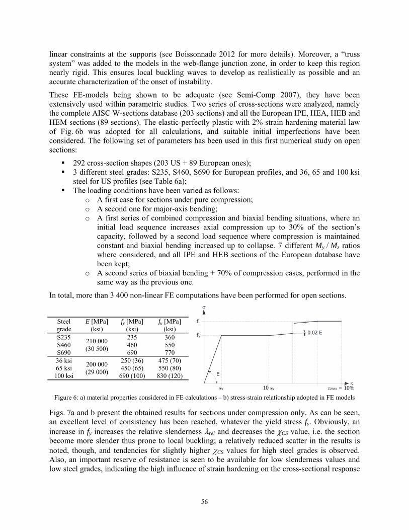
Steel grade
E [MPa] (ksi)
fy [MPa] (ksi)
fu [MPa] (ksi)
S235 210 000 (30 500)
235 360 S460 460 550 S690 690 770 36 ksi
200 000 (29 000)
250 (36) 475 (70) 65 ksi 450 (65) 550 (80) 100 ksi 690 (100) 830 (120)
Figure 6: a) material properties considered in FE calculations – b) stress-strain relationship adopted in FE models
Figs. 7a and b present the obtained results for sections under compression only. As can be seen, an excellent level of consistency has been reached, whatever the yield stress fy. Obviously, an increase in fy increases the relative slenderness rel and decreases the CS value, i.e. the section become more slender thus prone to local buckling; a relatively reduced scatter in the results is noted, though, and tendencies for slightly higher CS values for high steel grades is observed. Also, an important reserve of resistance is seen to be available for low slenderness values and low steel grades, indicating the high influence of strain hardening on the cross-sectional response
56
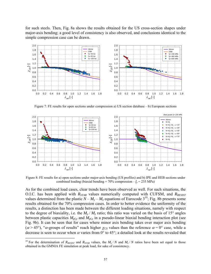
for such steels. Then, Fig. 8a shows the results obtained for the US cross-section shapes under major-axis bending; a good level of consistency is also observed, and conclusions identical to the simple compression case can be drawn.
rel [-]0.0 0.2 0.4 0.6 0.8 1.0 1.2 1.4 1.6 1.8
CS
[-]
0.0
0.2
0.4
0.6
0.8
1.0
1.2
1.4
1.6
1.8
2.0WinterDSMfy=36 ksify=65 ksify=100 ksi
rel [-]0.0 0.2 0.4 0.6 0.8 1.0 1.2 1.4 1.6 1.8
CS
[-]
0.0
0.2
0.4
0.6
0.8
1.0
1.2
1.4
1.6
1.8
2.0WinterDSMfy=235 MPafy=460 MPa fy=690 MPa
Figure 7: FE results for open sections under compression a) US section database – b) European sections
rel [-]0.0 0.2 0.4 0.6 0.8 1.0 1.2 1.4 1.6 1.8
CS
[-]
0.0
0.2
0.4
0.6
0.8
1.0
1.2
1.4
1.6
1.8
2.0WinterDSMfy=46 ksi fy=65 ksi fy=100 ksi
rel [-]0.0 0.2 0.4 0.6 0.8 1.0 1.2 1.4 1.6 1.8
CS
[-]
0.0
0.2
0.4
0.6
0.8
1.0
1.2
1.4
1.6
1.8
2.0WinterN+My
N+My+Mz - =15°
N+My+Mz - =30°
N+My+Mz - =45°
N+My+Mz - =60°
N+My+Mz - =75°
N+Mz
Steel grade fy=235 MPa
Figure 8: FE results for a) open sections under major-axis bending (US profiles) and b) IPE and HEB sections under
combined loading (biaxial bending + 70% compression – fy = 235 MPa)
As for the combined load cases, clear trends have been observed as well. For such situations, the O.I.C. has been applied with RSTAB values numerically computed with CUFSM, and RRESIST values determined from the plastic N – My – Mz equations of Eurocode 310; Fig. 8b presents some results obtained for the 70% compression cases. In order to better evidence the uniformity of the results, a distinction has been made between the different loading situations, namely with respect to the degree of biaxiality, i.e. the My / Mz ratio; this ratio was varied on the basis of 15° angles between plastic capacities Mpl,y and Mpl,z in a pseudo-linear biaxial bending interaction plot (see Fig. 9b). It can be seen that for cases where minor axis bending takes over major axis bending ( > 45°), “-groups of results” reach higher CS values than the reference = 0° case, while a decrease is seen to occur when varies from 0° to 45°; a detailed look at the results revealed that 10 For the determination of RRESIST and RSTAB values, the My / N and Mz / N ratios have been set equal to those obtained in the GMNIA FE simulation at peak load, for sake of consistency.
57
this was due to variations in the observed local buckling collapse modes, which obviously change with , as well as a certain conservatism in the N – My – Mz plastic interaction equations adopted herein.
The application of the O.I.C. to predict the resistance of open cross-sections is therefore seen to be fully appropriate, whatever the dimensions, steel grade or loading conditions; as presumed in the definition of a generalized relative slenderness, this approach is able to catch the governing parameters and to lead to consistent results, even for non-trivial situations and despite quite simple application steps. Consequently, the possibility to derive practical but accurate expressions for -curves exists, and is currently under completion (multiple mechanically-based expressions are foreseen, according to the trends observed for the combined loading cases).
3.2 Hollow sections
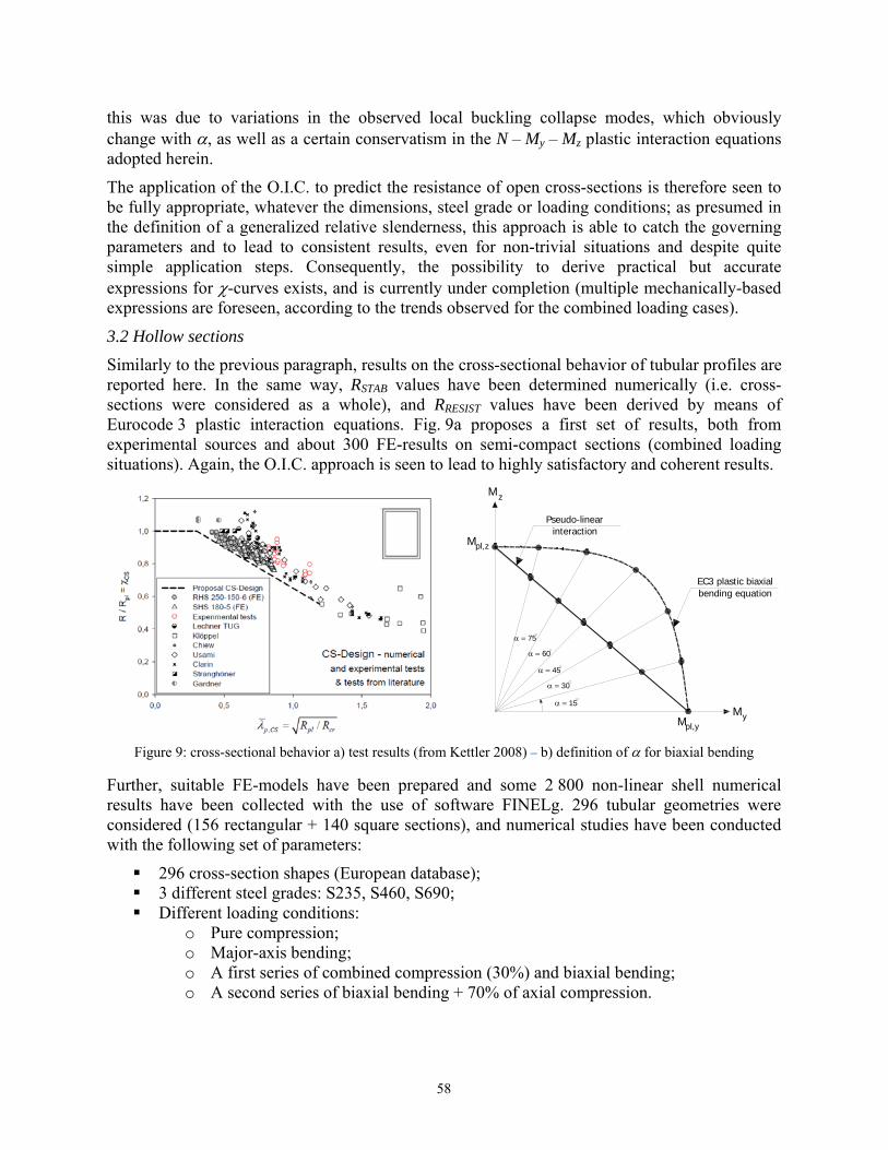
Similarly to the previous paragraph, results on the cross-sectional behavior of tubular profiles are reported here. In the same way, RSTAB values have been determined numerically (i.e. cross-sections were considered as a whole), and RRESIST values have been derived by means of Eurocode 3 plastic interaction equations. Fig. 9a proposes a first set of results, both from experimental sources and about 300 FE-results on semi-compact sections (combined loading situations). Again, the O.I.C. approach is seen to lead to highly satisfactory and coherent results.
15
30
45
60
75
Mz
Mpl,z
Mpl,y
My
EC3 plastic biaxialbending equation
Pseudo-linearinteraction
Figure 9: cross-sectional behavior a) test results (from Kettler 2008) – b) definition of for biaxial bending
Further, suitable FE-models have been prepared and some 2 800 non-linear shell numerical results have been collected with the use of software FINELg. 296 tubular geometries were considered (156 rectangular + 140 square sections), and numerical studies have been conducted with the following set of parameters:
296 cross-section shapes (European database); 3 different steel grades: S235, S460, S690; Different loading conditions:
o Pure compression; o Major-axis bending; o A first series of combined compression (30%) and biaxial bending; o A second series of biaxial bending + 70% of axial compression.
58
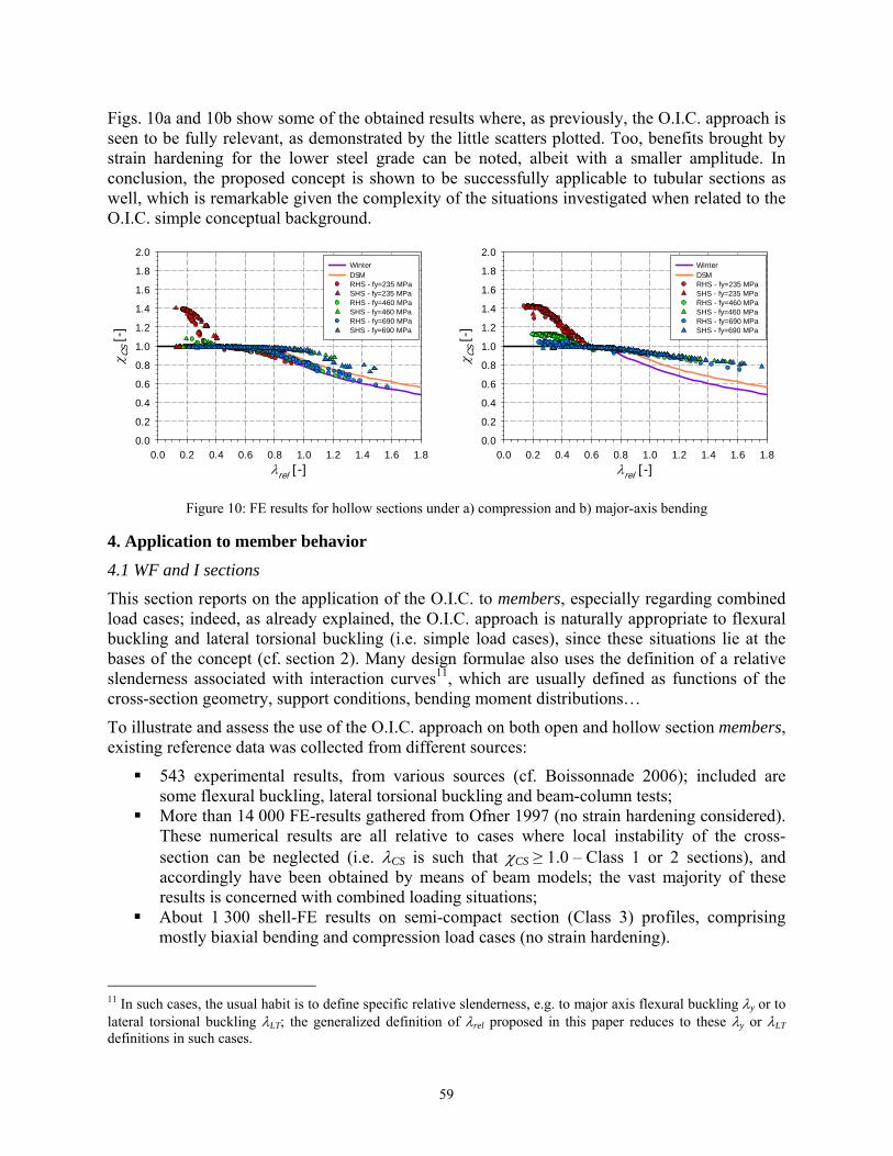
Figs. 10a and 10b show some of the obtained results where, as previously, the O.I.C. approach is seen to be fully relevant, as demonstrated by the little scatters plotted. Too, benefits brought by strain hardening for the lower steel grade can be noted, albeit with a smaller amplitude. In conclusion, the proposed concept is shown to be successfully applicable to tubular sections as well, which is remarkable given the complexity of the situations investigated when related to the O.I.C. simple conceptual background.
rel [-]0.0 0.2 0.4 0.6 0.8 1.0 1.2 1.4 1.6 1.8
CS
[-]
0.0
0.2
0.4
0.6
0.8
1.0
1.2
1.4
1.6
1.8
2.0WinterDSMRHS - fy=235 MPa SHS - fy=235 MPaRHS - fy=460 MPa SHS - fy=460 MPaRHS - fy=690 MPa SHS - fy=690 MPa
rel [-]0.0 0.2 0.4 0.6 0.8 1.0 1.2 1.4 1.6 1.8
CS
[-]
0.0
0.2
0.4
0.6
0.8
1.0
1.2
1.4
1.6
1.8
2.0WinterDSMRHS - fy=235 MPaSHS - fy=235 MPa RHS - fy=460 MPaSHS - fy=460 MPa RHS - fy=690 MPa SHS - fy=690 MPa
Figure 10: FE results for hollow sections under a) compression and b) major-axis bending
4. Application to member behavior
4.1 WF and I sections
This section reports on the application of the O.I.C. to members, especially regarding combined load cases; indeed, as already explained, the O.I.C. approach is naturally appropriate to flexural buckling and lateral torsional buckling (i.e. simple load cases), since these situations lie at the bases of the concept (cf. section 2). Many design formulae also uses the definition of a relative slenderness associated with interaction curves11, which are usually defined as functions of the cross-section geometry, support conditions, bending moment distributions…
To illustrate and assess the use of the O.I.C. approach on both open and hollow section members, existing reference data was collected from different sources:
543 experimental results, from various sources (cf. Boissonnade 2006); included are some flexural buckling, lateral torsional buckling and beam-column tests;
More than 14 000 FE-results gathered from Ofner 1997 (no strain hardening considered). These numerical results are all relative to cases where local instability of the cross-section can be neglected (i.e. CS is such that CS ≥ 1.0 – Class 1 or 2 sections), and accordingly have been obtained by means of beam models; the vast majority of these results is concerned with combined loading situations;
About 1 300 shell-FE results on semi-compact section (Class 3) profiles, comprising mostly biaxial bending and compression load cases (no strain hardening).
11 In such cases, the usual habit is to define specific relative slenderness, e.g. to major axis flexural buckling y or to lateral torsional buckling LT; the generalized definition of rel proposed in this paper reduces to these y or LT definitions in such cases.
59
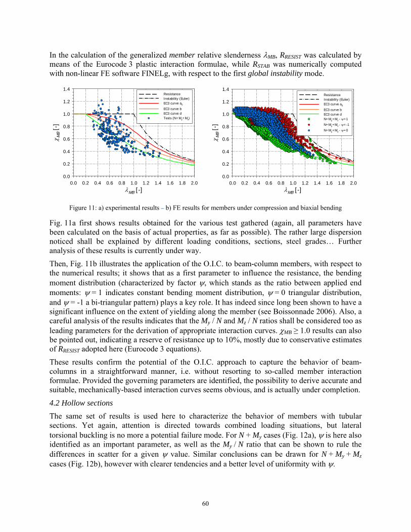
In the calculation of the generalized member relative slenderness MB, RRESIST was calculated by means of the Eurocode 3 plastic interaction formulae, while RSTAB was numerically computed with non-linear FE software FINELg, with respect to the first global instability mode.
MB [-]0.0 0.2 0.4 0.6 0.8 1.0 1.2 1.4 1.6 1.8 2.0
MB
[-]
0.0
0.2
0.4
0.6
0.8
1.0
1.2
1.4Resistance Instability (Euler)EC3 curve a0
EC3 curve bEC3 curve dTests (N+My+Mz)
MB [-]0.0 0.2 0.4 0.6 0.8 1.0 1.2 1.4 1.6 1.8 2.0
MB
[-]
0.0
0.2
0.4
0.6
0.8
1.0
1.2
1.4ResistanceInstability (Euler)EC3 curve a0
EC3 curve bEC3 curve dN+My+Mz - =1
N+My+Mz - =-1
N+My+Mz - =0
Figure 11: a) experimental results – b) FE results for members under compression and biaxial bending
Fig. 11a first shows results obtained for the various test gathered (again, all parameters have been calculated on the basis of actual properties, as far as possible). The rather large dispersion noticed shall be explained by different loading conditions, sections, steel grades… Further analysis of these results is currently under way.
Then, Fig. 11b illustrates the application of the O.I.C. to beam-column members, with respect to the numerical results; it shows that as a first parameter to influence the resistance, the bending moment distribution (characterized by factor , which stands as the ratio between applied end moments: = 1 indicates constant bending moment distribution, = 0 triangular distribution, and = -1 a bi-triangular pattern) plays a key role. It has indeed since long been shown to have a significant influence on the extent of yielding along the member (see Boissonnade 2006). Also, a careful analysis of the results indicates that the My / N and Mz / N ratios shall be considered too as leading parameters for the derivation of appropriate interaction curves. MB ≥ 1.0 results can also be pointed out, indicating a reserve of resistance up to 10%, mostly due to conservative estimates of RRESIST adopted here (Eurocode 3 equations).
These results confirm the potential of the O.I.C. approach to capture the behavior of beam-columns in a straightforward manner, i.e. without resorting to so-called member interaction formulae. Provided the governing parameters are identified, the possibility to derive accurate and suitable, mechanically-based interaction curves seems obvious, and is actually under completion.
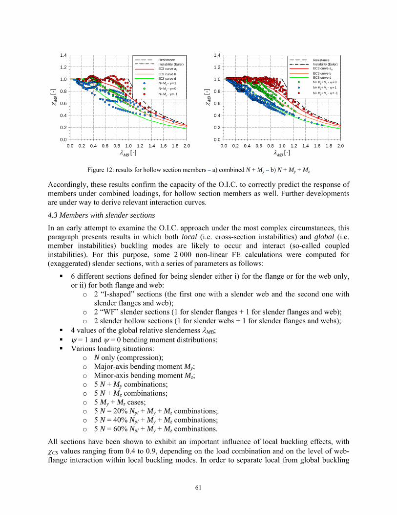
4.2 Hollow sections
The same set of results is used here to characterize the behavior of members with tubular sections. Yet again, attention is directed towards combined loading situations, but lateral torsional buckling is no more a potential failure mode. For N + My cases (Fig. 12a), is here also identified as an important parameter, as well as the My / N ratio that can be shown to rule the differences in scatter for a given value. Similar conclusions can be drawn for N + My + Mz cases (Fig. 12b), however with clearer tendencies and a better level of uniformity with .
60
MB [-]0.0 0.2 0.4 0.6 0.8 1.0 1.2 1.4 1.6 1.8 2.0
MB
[-]
0.0
0.2
0.4
0.6
0.8
1.0
1.2
1.4ResistanceInstability (Euler)EC3 curve a0
EC3 curve bEC3 curve dN+My - =1
N+My - =0
N+My - =-1
MB [-]0.0 0.2 0.4 0.6 0.8 1.0 1.2 1.4 1.6 1.8 2.0
MB
[-]
0.0
0.2
0.4
0.6
0.8
1.0
1.2
1.4ResistanceInstability (Euler)EC3 curve a0
EC3 curve bEC3 curve dN+My+Mz - =0
N+My+Mz - =1
N+My+Mz - =-1
Figure 12: results for hollow section members – a) combined N + My – b) N + My + Mz
Accordingly, these results confirm the capacity of the O.I.C. to correctly predict the response of members under combined loadings, for hollow section members as well. Further developments are under way to derive relevant interaction curves.
4.3 Members with slender sections
In an early attempt to examine the O.I.C. approach under the most complex circumstances, this paragraph presents results in which both local (i.e. cross-section instabilities) and global (i.e. member instabilities) buckling modes are likely to occur and interact (so-called coupled instabilities). For this purpose, some 2 000 non-linear FE calculations were computed for (exaggerated) slender sections, with a series of parameters as follows:
6 different sections defined for being slender either i) for the flange or for the web only, or ii) for both flange and web:
o 2 “I-shaped” sections (the first one with a slender web and the second one with slender flanges and web);
o 2 “WF” slender sections (1 for slender flanges + 1 for slender flanges and web); o 2 slender hollow sections (1 for slender webs + 1 for slender flanges and webs);
4 values of the global relative slenderness MB; = 1 and = 0 bending moment distributions; Various loading situations:
o N only (compression); o Major-axis bending moment My; o Minor-axis bending moment Mz; o 5 N + My combinations; o 5 N + Mz combinations; o 5 My + Mz cases; o 5 N = 20% Npl + My + Mz combinations; o 5 N = 40% Npl + My + Mz combinations; o 5 N = 60% Npl + My + Mz combinations.
All sections have been shown to exhibit an important influence of local buckling effects, with CS values ranging from 0.4 to 0.9, depending on the load combination and on the level of web-flange interaction within local buckling modes. In order to separate local from global buckling
61
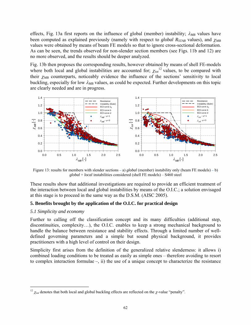
effects, Fig. 13a first reports on the influence of global (member) instability; MB values have been computed as explained previously (namely with respect to global RSTAB values), and MB values were obtained by means of beam FE models so that to ignore cross-sectional deformation. As can be seen, the trends observed for non-slender section members (see Figs. 11b and 12) are no more observed, and the results should be deeper analyzed.
Fig. 13b then proposes the corresponding results, however obtained by means of shell FE-models where both local and global instabilities are accounted for; tot
12 values, to be compared with their MB counterparts, noticeably evidence the influence of the sections’ sensitivity to local buckling, especially for low MB values, as could be expected. Further developments on this topic are clearly needed and are in progress.
MB [-]0.0 0.5 1.0 1.5 2.0 2.5
MB
[-]
0.0
0.2
0.4
0.6
0.8
1.0
1.2
1.4ResistanceInstability (Euler)EC3 curve a0
EC3 curve bEC3 curve dMB - =1
MB
- =0
MB [-]0.0 0.5 1.0 1.5 2.0 2.5
tot [
-]
0.0
0.2
0.4
0.6
0.8
1.0
1.2
1.4ResistanceInstability (Euler)EC3 curve a0
EC3 curve bEC3 curve dtot - =1
tot- =0
Figure 13: results for members with slender sections – a) global (member) instability only (beam FE models) – b)
global + local instabilities considered (shell FE models) – S460 steel
These results show that additional investigations are required to provide an efficient treatment of the interaction between local and global instabilities by means of the O.I.C.; a solution envisaged at this stage is to proceed in the same way as the D.S.M. (AISC 2005).
5. Benefits brought by the application of the O.I.C. for practical design
5.1 Simplicity and economy
Further to calling off the classification concept and its many difficulties (additional step, discontinuities, complexity…), the O.I.C. enables to keep a strong mechanical background to handle the balance between resistance and stability effects. Through a limited number of well-defined governing parameters and a simple but sound physical background, it provides practitioners with a high level of control on their design.
Simplicity first arises from the definition of the generalized relative slenderness: it allows i) combined loading conditions to be treated as easily as simple ones – therefore avoiding to resort to complex interaction formulae –, ii) the use of a unique concept to characterize the resistance
12 tot denotes that both local and global buckling effects are reflected on the -value “penalty”.
62
of sections as well as the resistance of members, and iii) the treatment of all sections shapes in a unique procedure, i.e. no distinction is made between open and tubular sections for example13.
Then, the use of modern (and sometimes free) powerful analysis tools such as CUFSM, GBTUL, MASTAN… provides quick and accurate results, and deeply simplifies the determination of critical stresses (or, equivalently, of RSTAB) as well as the resolution of so-called “coupled instabilities” problems, i.e. involving both cross-sectional (local) and member (global) instabilities.
Next, the definition of interaction curves permits to consider the influence of imperfections, and establishes smooth and continuous transitions along the slenderness range. As a consequence, the fastidious determination of effective properties is no more necessary, “slender” sections being designed in the same way as others.
Although being applied in this paper to structural steel design, the O.I.C. remains open to any material, in particular to elements made of tomorrow’s high performance materials highly susceptible to buckle (e.g. columns or beam-columns made of high performance concrete, fiber-reinforced concrete, high strength steel, composite materials…). The relative influence of instability on the carrying capacity of members will indeed increase with their slenderness – directly linked to the increase in resistance , so that an accurate treatment of the interaction will become imperative. The application of the O.I.C. to such materials is relatively simple, as the bases and concept remain whatever the material considered.
As for economic aspects, one shall begin by pointing out simpler and quicker design procedures. Then, the treatment of the cross-section as a whole, made possible thanks to modern efficient and powerful analytical tools, generates notably more favorable results. Also, the possibility to benefit from inelastic effects exists in all loading cases and whatever the slenderness, since continuous transitions are offered from “plastic” to “slender” situations.
Last, the possibility to account for strain hardening positive effects, a feature enabled by the O.I.C., brings further material savings, especially for materials that exhibit a high degree of nonlinearity and strain hardening (high strength steel, stainless steel, aluminum…)
5.2 High strength steels
As high strength steels are expected to become more and more commonly used for buildings in a near future, the relative influence of instabilities will increase significantly and become decisive. As already explained, for 65 ksi steels and above, many cross-sections used in practice will be concerned with local instabilities, which, to date and for the vast majority of design standards, means long and tedious iterative calculations. Improvements should therefore be brought to the actual state-of-the art in this respect, and result in new methods for predicting the resistance of sections and members in cases where instability effects are important, which is precisely what the O.I.C. is meant for.
Moreover, it shall be recalled that the interest of resorting to high strength steels should somewhat be tempered due to serviceability reasons: if metallurgists have been able to propose significantly higher steel grades, they have not been able to appreciably change the Young’s modulus of steel, which results in serviceability to control the design more often. To re-balance
13 It may be noted that this differentiation between open and hollow section design rules applies in many modern design standards, such as in Eurocode 3.
63
the serviceability vs strength equation is therefore imperative in order to embrace the potential of high strength steel and ultra-high strength steels. This can be achieved through many levels of optimization (moving material around in existing sections, explore entirely new shapes, see Schafer 2006).
5.3 Modern design tools
More direct calculations of resistance and the emergence of new design approaches can only be achieved through the development of new analytical tools such as CUFSM, GBTUL… In addition to offering the highly beneficial features already detailed, they enable our knowledge to shift from pages of complex and approximate, long formulae into more general, mechanically based tools. For sake of practical efficiency, they however deserve improvements and simplifications before being economically used on a daily basis for design. This turn in practical habits finally is equivalent to the one done in the 80’s for the computer-aided determination of internal forces and moments (nowadays common and essential software), however on the “resistance side”. This will also require changes in the education of tomorrow’s engineers to such new tools and methods, which is the responsibility of Academia.
6. Conclusions – Actual and future developments
6.1 Conclusions
In the present paper, the Overall Interaction Concept has been shown to be a fully appropriate alternative to the current well-known design rules to account for the interaction between resistance and instability effects. In particular, results on both sections and members (i.e. local and/or global instability), open or tubular sections, simple or combined load cases have been presented; they evidence that, although being based on simple principles and with straightforward application steps, the O.I.C. may appear as an accurate and consistent approach, and serve as a basis for the next generation of standards and practical tools, especially in the frame of an increasing use of high steel or ultra-high steel grades.
6.2 Undergoing research works
The O.I.C. approach is actually at the core of the S.T.S.S. project (“Simple Tools Sell Steel”, STSS 2012), whose main objective is to develop and assess new design concepts to predict accurately the response of members made of standard and high-strength steel up to collapse. The project consists in 7 work packages organized as follows:
WP1 – Cross-Sectional and Member Resistance – I and H-shaped Sections; WP2 – Cross-Sectional and Member Resistance – Hollow or Tubular Sections; WP3 – Behavior of Non-linear Materials, including Strain Hardening Effects; WP4 – Influence of Shear Stresses on Cross-sectional Resistance; WP5 – Development of Criteria to allow for Plastic Analysis; WP6 – Development of Practical Tools and Design Formulae; WP7 – Incorporation of Design Formulae in Design Standards.
Many partners are currently involved in the project, both from the industrial side (ArcelorMittal, CIDECT, Stahl Gerlafingen, TataSteel, Vallourec & Mannesmann, Voestalpine Krems…) and from the academic side (University of Liège, Johns Hopkins University, Imperial College London, Technical University of Graz, Virginia Tech, Technical University of Lisbon, University of Applied Sciences of Western Switzerland – Fribourg…).
64
In an international effort, almost all WPs are actually under development, involving deep, varied and extensive activities, both at the experimental, numerical, theoretical and practical level. Also, several attempts to bring the best features of the D.S.M., of the C.S.M. and of the O.I.C. under a common umbrella are contemplated within S.T.S.S.
Besides, O.I.C.-based investigations on high and ultra-high performance fiber concrete elements (columns and beam-columns) are currently under way.
6.3 Future developments and possible extensions
The future research directions related to an O.I.C. approach will first be oriented towards its application to other materials, in situations where instability is of prime importance. This concerns for example members made of composite sections, stainless steel, aluminum, ultra-high performance concrete with fibers, structural glass…
Moreover, the development of new cross-sectional shapes, deliberately slender, is intended with the objective of taking the benefits from the new generation of high strength steel. Also, investigations within fire and earthquake steel design will become necessary, as a consequence of the calling off of the classification concept. Further, the O.I.C. approach and principles, as described herein, should appreciably improve the design of specific members where coupled instabilities and/or complex solutions to implement require (partial) numerical solutions and the associated conceptual framework (e.g. tapered members, cellular beams…). Last, in the perspective of seeing the O.I.C. embedded in various standards worldwide, the O.I.C. should allow for a certain harmonization of standard and design habits, since relying on a general and global concept.
Notations
rel Generalized relative slenderness
RRESIST Load factor (ratio) with respect to “resistance” aspects, i.e. driven by material resistance only (no instability)
RSTAB Load factor (ratio) with respect to “stability” aspects, i.e. perfect material (yield stress = infinity) and perfect element (no material nor geometrical imperfections)
Reduction factor (penalty due to instability and imperfections on the “pure resistant” behavior)
CS Reduction factor due to cross-sectional (CS – local) instability
MB Reduction factor due to member buckling (MB – global instability)
N Axial force (compression)
My Major axis bending moment
Mz Minor axis bending moment
b Width of plate/wall
t Thickness of plate/wall
fy Yield stress
cr Plate critical stress
Parameter indicating the ratio of “biaxiality”, see Fig. 9a
Ratio between end moments (-1 ≤ ≤ 1)
65
References
AISC (2001). “Manual of Steel Construction, Load and Resistance Factor Design”, AISC, Chicago, Illinois. AISC (2005). Specification for structural steel buildings. American Institute of Steel Construction, Chicago, IL.
ANSI/ASIC 360-05. Bebiano R., Pina P., Silvestre N. and Camotim D. (2008). “GBTUL – Buckling and Vibration Analysis of Thin-
Walled Members”, DECivil/IST, Technical University of Lisbon (http://www.civil.ist.utl.pt/gbt). Boissonnade N. (2011). “The Concept of Cross-section Classes in Eurocode 3 into Question”, ECCS TC8 meeting,
Lisbon, June 3rd. Boissonnade N., Greiner R., Jaspart J.P., Lindner J. (2006) “Rules for Member Stability in EN 1993–1–1;
Background documentation and design guidelines”, Eds. Mem Martins, Portugal, E.C.C.S. – ISBN 92-9147-000-84, Vol. 119, 259 pages.
Boissonnade, N., Somja, H. (2012). “Influence of Imperfections in FEM Modeling of Lateral Torsional Buckling”. Proceedings of the Annual Stability Conference, Structural Stability Research Council, Grapevine, Texas, April 18-21.
BSI British Standards Institution (2000) BS5950. The Structural Use of Steelwork in Building: Part 1: Code of Practice for Design: Rolled and Welded Sections, BSI, London.
CEN (Comité Européen de Normalisation) (2005). “Eurocode 3: Design of Steel Structures, Part 1–1: General rules and rules for buildings (EN 1993-1-1)”, Brussels.
CEN (Comité Européen de Normalisation) (2005). “Eurocode 3: Design of Steel Structures, Part 1–5: Design of plated structures (EN 1993-1-1)”, Brussels.
DIN 18800 1-4: 1990 (1990). “Stahlbauten.” Beuth Verlag GmbH, Berlin. Gardner, Leroy (2008). “The continuous strength method”. Proc. Institution of Civil Engineers: Structures and
Buildings, vol. 161, n°3, p 127-133. Gardner L., Wang F., Liew A. (2011). “Influence of strain hardening on the behavior and design of steel structures”,
International Journal of Structural Stability and Dynamics, Vol. 11, pp. 855-875. Johansson B., Maquoi R., Sedlacek G., Müller C., Beg D. (2007). “Commentary and worked examples to EN 1993-
1-5 Plated elements”, JRC Scientific and Technical Reports, First Edition, 242 p. Kettler M. (2008). “Elastic-plastic cross-sectional resistance of semi-compact H- and hollow sections”. PhD Thesis,
Graz Technical University. Li Y., Rossi B. (2012). “Finite element model for the extension of the Direct Strength Method to hot-rolled profile
cross-sections”, Proc. of the Nordic Steel Construction Conference, Oslo, Norway, 5-7 September. Li Z., Schafer B. (2010) “Buckling analysis of cold-formed steel members with general boundary conditions using
CUFSM: conventional and constrained finite strip methods.” Proceedings of the 20th Int.. Spec. Conf. on Cold-Formed Steel Structures, St. Louis, MO. November, 2010.
Maquoi R., Rondal J. (1978). “Mise en équation des nouvelles courbes européennes de flambement”, Construction Métallique, n°1, pp. 17-30.
Massonnet C. (1976). “Forty Years of Research on Beam-Columns in Steel”, Solid Mechanics Archives, Noordhoff International Publishing, Leyden, Vol.1, n°1.
Merchant, W. (1954). “The failure load of rigid jointed frameworks as influenced by stability”, The Structural Engi neer, 32, No. 7, July, pp. 185–90.
Non-linear finite element analysis program “FINELg” (2012), User’s Manual, version 9.3, ArGEnCo Department, University of Liège, Greisch Info S.A., Liège, Belgium.
Ofner R. (1997) “Traglast von Staben aus Stahl bei Druck und Biegung”. PhD Thesis, Graz Technical University. “Plastic member capacity of semi-compact steel sections – a more economic design (Semi-Comp)” (2007). Final
report (01/01/06 – 30/06/07) – RFCS – Steel RTD (Contract RFS-CR-04044). SA (1998) AS4100–1998 Steel Structures, Standards Australia, Sydney, Australia. Schafer B. (2006). “Cross-section Stability of Structural Steel”, AISC Faculty Fellowship Research Project. Seif M., Schafer B. (2010). “Local buckling of structural steel shapes”, Journal of Constructional Steel Research,
vol. 66, pp. 1232-1247. S.T.S.S. (2012). “Research project STSS – Simple Tools Sell Steel” (http://www.ims.org/2012/02/stss-simple-tools-
sell-steel/). Ziemian, R., McGuire W. (2009). MASTAN2, www.mastan2.com.
66