Embed Size (px)
Citation preview
The Outer Planets / Solar Probe Project : “Between an Ocean, a Rock, and a Hot Place”
Robert W. Maddock Jet Propulsion Laboratory, California Institute of Technology
4800 Oak Grove Dr., Mail Stop 30 1 - 160 Pasadena, CA 9 1 109
Karla B. Clark Jet Propulsion Laboratory, Californialnstitute of Technology
4800 Oak Grove Dr., Mail Stop 301-1 60 Pasadena, CA 9 1 109
Curt A. Henry Jet Propulsion Laboratory, California Institute of Technology
4800 Oak Grove Dr., Mail Stop 301-160 Pasadena, CA 9 1 109
Pamela J. Hoffman Jet Propulsion Laboratory, California Institute of Technology
4800 Oak Grove Dr., Mail Stop 301-320 Pasadena, CA 9 1 109
8 18-354- 1443
8 18-354-9033
818-393-3851
81 8-354-6756 [email protected] ‘
Abstract -As part of NASA’s Origins program, the Outer Plan- ets / Solar Probe Project (formerly known as the Ice and Fire Preprojects) was established in early 1998. This flight project is composed of three challenging and exciting missions which span the far reaches of the solar system. Europa Orbiter, with a planned launch in November of 2003, will travel to Jupiter‘s moon, Europa, in search of a subsurface liquid water ocean which, if found, could provide a possible environment for the evolution of extraterrestrial life. Pluto-Kuiper Express, with a planned launch in December 2004, will travel to the last planet of the solar system yet to be visited and studied by a robotic spacecraft, and possibly continue on an extended mission to study the remnants from the creation of the solar system found within the Kuiper Belt. Solar Probe, with a planned launch in February 2007, will travel into the heart of the solar system, at
Copywrite 0 1999 The Institute of Electrical and Electron- ics Engineers, Inc. The U S . Government has a royalty-free license to excercise all rights under the copyright claimed herein for Governmental Purposes. All other rights are reserved by the copyright owner.
three solar radii from the “surface” of the Sun, to study the structure of the corona as well as the source and mechanisms for the creation and acceleration of the Solar Wind.
In order to ensure success of each of these missions, under stringent mass, power, and cost constraints, the Outer Planets / Solar Probe Project will rely heavily on several new tech- nologies. Many of these technologies are currently being de- veloped by the Deep Space System Technology Program‘s First Delivery Project (otherwise known as X2000) and in- clude: low mass, low power, and radiation hard avionics; an avionics packaging scheme which utilizes embedded cabling; a high efficiency, low mass and low power transponder; a mN (milli-Newton) thruster and variable liquid regulator; and a unified flight and ground system software core and architec- ture. These and other mission-specific technologies will not only enable the Outer Planet / Solar Probe missions, but also provide the foundation upon which technology is to be devel- oped for missions well into the future.
This paper summarizes each of the Outer Planet Solar Probe missions, including the science objectives, mission descrip- tion, and current spacecraft concepts. The commonalities be-
tween these three missions and their reliance on the X2000 project, as well as the mission specific technology develop- ments required for each mission, are also discussed.
A R P S A.U. CISM DSN DSSTP ELV EO1 EUV HGA IMU IR IUS JGA JOI JPL MCM MDS MGA NASA
OP/SP PJR PKE RHU Rs RW SDST SDT STS
uv VLR x2000 X-SSPA
ACRONYM LIST Advanced Radioisotope Power Source Astronomical Unit Center for Integrated Space Microsystems Deep Space Network Deep Space System Technology Program Expendable Launch Vehicle Europa Orbit Insertion Extreme Ultraviolet High Gain Antenna Inertial Measurement Unit Infrared Inertial Upper Stage Jupiter Gravity Assist Jupiter Orbit Insertion Jet Propulsion Laboratory Multi-chip Module Mission Data System Medium Gain Antenna National Aeronautics and Space Administration Outer Planets / Solar Probe Perijove Raise Pluto-Kuiper Express Radioisotope Heater Unit Solar Radii Reaction Wheel Small Deep Space Transponder Science Definition Team Space Transportation System (Space Shuttle) Ultraviolet Variable Liquid Regulator DSSTP First Delivery Project X-band Solid State Power Amplifier
TABLE OF CONTENTS 1 . INTRODUCTION 2. PROJECT OVERVIEW 3. EUROPA ORBITER 4. PLUTO-KUIPER EXPRESS 5. SOLAR PROBE 6. SUMMARY 7. ACKNOWLEDGMENTS 8. REFERENCES 9. ABOUT THE AUTHORS
1 . INTRODUCTION
Early in the next century, the National Aeronautics and Space Administration (NASA) and the Jet Propulsion Laboratory (JPL) will launch the first set of missions in an ongoing pro- gram to study the solar system. As part of the NASA Origins initiative, these missions will search for clues into the origins and development of the solar system as well as life here on Earth and possibly elsewhere. The Outer Planets / Solar Probe (OP/SP) Project is comprised of this first set of missions: Europa Orbiter, currently planned to launch in November 2003; Pluto-Kuiper Express, in December 2004; and Solar Probe, in February 2007. These missions, as well as the technology de- velopment required to enable their success, including low mass, low power, and low cost spacecraft components, will set the standards for deep space exploration well into the future.
Of course, many final decisions have yet to be made on the mission implementation and spacecraft design. Many trades and analyses are still on-going and have yet to be completed. Several key review and decision processes are also yet to be completed, including the environmental impact process. What is described here is the current (October 1998) proposed baseline design.
2. PROJECT OVERVIEW The Outer Planets / Solar Probe (OP/SP) Project was estab- lished in early 1998 as the first flight project in an ongoing Outer Planets / Solar Probe Exploration Program within NASA, This purpose of this program is to enable deep-space exploration by driving technology development and sharing cost among several missions. Spacecraft, launch systems, and mission operations costs must all fit within the budget of a single program, thus encouraging system level and program wide (between multiple missions) trades to minimize costs. The current plan of the OP/SP Program is to launch a mission roughly every 2 years (on average), beginning in 2003.
The OP/SP Project is the continuation of the Ice and Fire Preprojects, established in late 1996, and consists of three very exciting planetary exploration ventures. These are :
Europa Orbiter mission: place a spacecraft into Europa orbit and explore Jupiter’s icy moon in search of a subsurface ocean, and to identify pos- sible landing sites for future missions
Pluto-Kuiper Express mission : reconnaissance of the only planet in the solar system that has yet to be visited and possibly objects within the vast Kuiper Belt beyond Pluto to learn and un- derstand more about the formation of the solar system
Solar Probe mission : first solar mission to go inside the stellar corona to increase the under-

Option Europa : Direct STS/IUS/Star48V Pluto : JGA STS/IUS/Star48V, Deltalll-AtlasllV Star48V Solar Probe : JGI Deltalll-Atlaslll/ Star48V
Pluto : JGA STS/IUS/Star48V, Deltalll-AtlaslW Star48V Europa : Direct STS/IUS/Star48V
Solar Probe : JGP Deltalll-Atlaslll/ Star48V
7
Europa arrival sensitive to trajectoly design and launch date
Figure 2.1: Outer Planets / Solar Probe Project Mission Timeline
standing of those processes of the heating and acceleration of the solar wind and to obtain the first viewing of the solar poles at a resolution better than that achieved on Earth
Figure 2.1 shows the current proposed OP/SP mission sched- ule. An option to switch the Europa Orbiter and Pluto-Kuiper Express launch dates is still being maintained in the event that technology development required for the Europa Orbiter space- craft is not ready in time.
The program level budget constraint drives the use of com- mon components and technology across the different missions. Although the three OP/SP missions may not appear on the surface to have much in common, they actually share many similarities. One of these is in the mission design, where the proposed baselines call for each mission to be sent to Jupiter before ultimately reaching its final destination. (This is dis- cussed further in the mission description sections below.) An- other very important similarity between these missions is the requirement for low mass, low power, low cost spacecraft com- ponents. These missions also span the entire environment spec- trum a spacecraft could encounter in flight, including: long lifetime and long periods of cruise, severe radiation environ- ment, and severe thermal environments. Technology which can be developed to survive one or all of these environments, while maintaining the low mass, low power, and low cost re- quirement, is certain to help not only these missions, but mis- sions well into the future.
Much of the new technology required by the OP/SP Project is being developed by the Deep Space System Technology Program's (DSSTP) First Delivery Project (otherwise known as X2000). DSSTP is chartered with continually developing the next generation of advanced avionics, software, and other new technologies. From this, current and future missions can draw upon recent technology advances and utilize those state- of-the-art spacecraft components which make sense for the individual mission. This minimizes the development costs of the individual missions, while improving performance and minimizing risk.
In partnership with the Center for Integrated Space Microsystems (CISM), a NASA Center of Excellence, X2000 will develop advanced avionics which can be utilized by all OP/SP missions, as well as other current and fiture flight projects. A summary of the items which X2000 will develop and deliver for use on the OP/SP, and other interested mis- sions, is provided in Table 2.1.
Another area in which many missions will benefit, including the OP/SP missions, is that of ground and flight data systems. In the past, each individual mission found itself developing a flight and ground data system, as well as an operation strat- egy, which was unique to that mission. Attempts to inherit software and other flight and ground system elements were oftentimes greatly hindered by lack of foresight while in de- velopment phase. Even if componemts of these systems were inherited, the mission would frequently have to make major
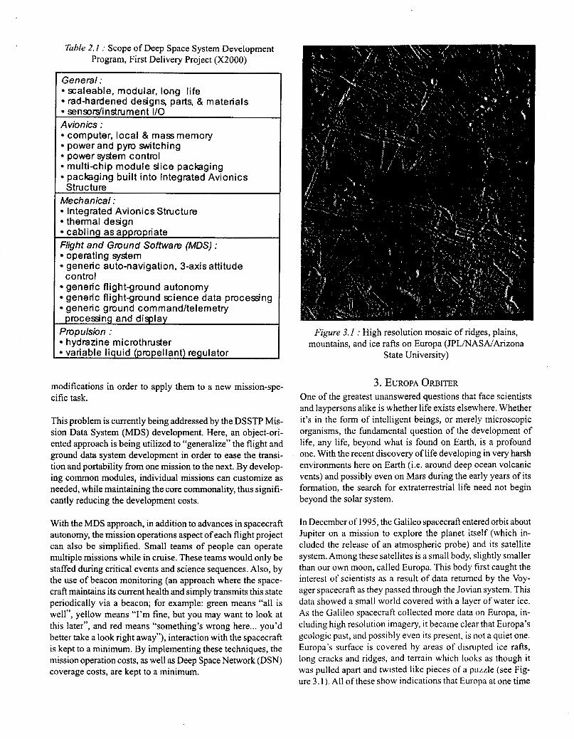
Table 2. I : Scope of Deep Space System Development Program, First Delivery Project (X2000)
General : scaleable, modular, long life rad-hardened designs, parts, & materials sensodinstrument I/O
Avionics : computer, local & mass memory power and pyro switching power system control mult ichip module slice packaging packaging built into Integrated Avionics Structure
Mechanical : Integrated Avionics Structure thermal design cabling asappropriate
Flight and Ground Software (MDS) : operating system generic auto-navigation, 3-axis attitude
generic flightground autonomy generic flightground science data processing generic ground command/telemetry processing and display
Propulsion : hydrazine microthruster variable liquid (propellant) regulator
control
modifications in order to apply them to a new mission-spe- cific task.
This problem is currently being addressed by the DSSTP Mis- sion Data System (MDS) development. Here, an object-ori- ented approach is being utilized to “generalize” the flight and ground data system development in order to ease the transi- tion and portability from one mission to the next. By develop- ing common modules, individual missions can customize as needed, while maintaining the core commonality, thus signifi- cantly reducing the development costs.
With the MDS approach, in addition to advances in spacecraft autonomy, the mission operations aspect of each flight project can also be simplified. Small teams of people can operate multiple missions while in cruise. These teams would only be staffed during critical events and science sequences. Also, by the use of beacon monitoring (an approach where the space- craft maintains its current health and simply transmits this state periodically via a beacon; for example: green means “all is well”, yellow means “I’m fine, but you may want to look at this later“, and red means “something’s wrong here ... you’d better take a look right away”), interaction with the spacecraft is kept to a minimum. By implementing these techniques, the mission operation costs, as well as Deep Space Network (DSN) coverage costs, are kept to a minimum.
Figure 3.1 : High resolution mosaic of ridges, plains, mountains, and ice rafts on Europa (JPLINASAlArizona
State University)
3. EUROPA OR~ITER One of the greatest unanswered questions that face scientists and laypersons alike is whether life exists elsewhere. Whether it’s in the form of intelligent beings, or merely microscopic organisms, the fundamental question of the development of life, any life, beyond what is found on Earth, is a profound one. With the recent discovery of life developing in very harsh environments here on Earth (i.e. around deep ocean volcanic vents) and possibly even on Mars during the early years of its formation, the search for extraterrestrial life need not begin beyond the solar system.
In December of 1995, the Galileo spacecraft entered orbit about Jupiter on a mission to explore the planet itself (which in- cluded the release of an atmospheric probe) and its satellite system. Among these satellites is a small body, slightly smaller than our own moon, called Europa. This body first caught the interest of scientists as a result of data returned by the Voy- ager spacecraft as they passed through the Jovian system. This data showed a small world covered with a layer of water ice. As the Galileo spacecraft collected more data on Europa, in- cluding high resolution imagery, it became clear that Europa’s geologic past, and possibly even its present, is not a quiet one. Europa’s surface is covered by areas of disrupted ice rafts, long cracks and ridges, and terrain which looks as though it was pulled apart and twisted like pieces of a puzzle (see Fig- ure 3.1 ). All of these show indications that Europa at one time
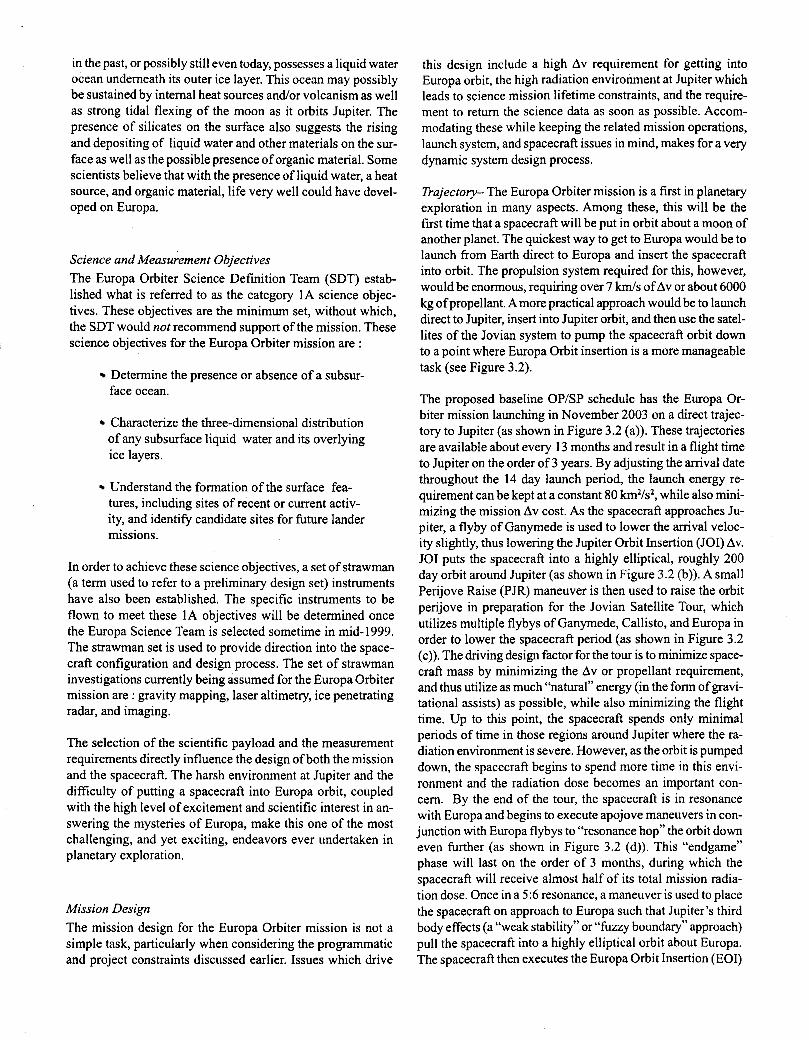
in the past, or possibly still even today, possesses a liquid water ocean underneath its outer ice layer. This ocean may possibly be sustained by internal heat sources and/or volcanism as well as strong tidal flexing of the moon as it orbits Jupiter. The presence of silicates on the surface also suggests the rising and depositing of liquid water and other materials on the sur- face as well as the possible presence of organic material. Some scientists believe that with the presence of liquid water, a heat source, and organic material, life very well could have devel- oped on Europa.
Science and Measurement Objectives The Europa Orbiter Science Definition Team (SDT) estab- lished what is referred to as the category 1A science objec- tives. These objectives are the minimum set, without which, the SDT would not recommend support of the mission. These science objectives for the Europa Orbiter mission are :
Determine the presence or absence of a subsur- face ocean.
Characterize the three-dimensional distribution of any subsurface liquid water and its overlying ice layers.
Understand the formation of the surface fea- tures, including sites of recent or current activ- ity, and identify candidate sites for future lander missions.
In order to achieve these science objectives, a set of strawman (a term used to refer to a preliminary design set) instruments have also been established. The specific instruments to be flown to meet these 1A objectives will be determined once the Europa Science Team is selected sometime in mid-1999. The strawman set is used to provide direction into the space- craft configuration and design process. The set of strawman investigations currently being assumed for the Europa Orbiter mission are : gravity mapping, laser altimetry, ice penetrating radar, and imaging.
The selection of the scientific payload and the measurement requirements directly influence the design of both the mission and the spacecraft. The harsh environment at Jupiter and the difficulty of putting a spacecraft into Europa orbit, coupled with the high level of excitement and scientific interest in an- swering the mysteries of Europa, make this one of the most challenging, and yet exciting, endeavors ever undertaken in planetary exploration.
Mission Design The mission design for the Europa Orbiter mission is not a simple task, particularly when considering the programmatic and project constraints discussed earlier. Issues which drive
this design include a high Av requirement for getting into Europa orbit, the high radiation environment at Jupiter which leads to science mission lifetime constraints, and the require- ment to return the science data as soon as possible. Accom- modating these while keeping the related mission operations, launch system, and spacecraft issues in mind, makes for a very dynamic system design process.
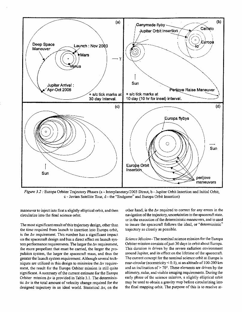
Trajectory- The Europa Orbiter mission is a first in planetary exploration in many aspects. Among these, this will be the first time that a spacecraft will be put in orbit about a moon of another planet. The quickest way to get to Europa would be to launch from Earth direct to Europa and insert the spacecraft into orbit. The propulsion system required for this, however, would be enormous, requiring over 7 km/s of Av or about 6000 kg of propellant. Amore practical approach would be to launch direct to Jupiter, insert into Jupiter orbit, and then use the satel- lites of the Jovian system to pump the spacecraft orbit down to a point where Europa Orbit insertion is a more manageable task (see Figure 3.2).
The proposed baseline OPISP schedule has the Europa Or- biter mission launching in November 2003 on a direct trajec- tory to Jupiter (as shown in Figure 3.2 (a)). These trajectories are available about every 13 months and result in a flight time to Jupiter on the order of 3 years. By adjusting the amval date throughout the 14 day launch period, the launch energy re- quirement can be kept at a constant 80 km2/s2, while also mini- mizing the mission Av cost. As the spacecraft approaches Ju- piter, a flyby of Ganymede is used to lower the arrival veloc- ity slightly, thus lowering the Jupiter Orbit Insertion (JOI) Av. JOI puts the spacecraft into a highly elliptical, roughly 200 day orbit around Jupiter (as shown in Figure 3.2 (b)). A small Perijove Raise (PJR) maneuver is then used to raise the orbit perijove in preparation for the Jovian Satellite Tour, which utilizes multiple flybys of Ganymede, Callisto, and Europa in order to lower the spacecraft period (as shown in Figure 3.2 (c)). The driving design factor for the tour is to minimize space- craft mass by minimizing the Av or propellant requirement, and thus utilize as much “natural” energy (in the form of gravi- tational assists) as possible, while also minimizing the flight time. Up to this point, the spacecraft spends only minimal periods of time in those regions around Jupiter where the ra- diation environment is severe. However, as the orbit is pumped down, the spacecraft begins to spend more time in this envi- ronment and the radiation dose becomes an important con- cern. By the end of the tour, the spacecraft is in resonance with Europa and begins to execute apojove maneuvers in con- junction with Europa flybys to “resonance hop” the orbit down even further (as shown in Figure 3.2 (d)). This “endgame” phase will last on the order of 3 months, during which the spacecraft will receive almost half of its total mission radia- tion dose. Once in a 5:6 resonance, a maneuver is used to place the spacecraft on approach to Europa such that Jupiter’s third body effects (a “weak stability” or “fuzzy boundary” approach) pull the spacecraft into a highly elliptical orbit about Europa. The spacecraft then executes the Europa Orbit Insertion (EOI)
I
\ \
+ s/c tick marks at W e c r J
10 day (10 hr for inset) interval.
maneuvers
Figure 3.2 : Europa Orbiter Trajectory Phases (a - Interplanetary/2003 Direct, b - Jupiter Orbit Insertion and Initial Orbit, c - Jovian Satellite Tour, d - the “Endgame” and Europa Orbit Insertion)
maneuver to inject into first a slightly elliptical orbit, and then circularize into the final science orbit.
The most significant result of this trajectory design, other than the time required from launch to insertion into Europa orbit, is the Av requirement. This number has a significant impact on the spacecraft design and has a direct effect on launch sys- tem performance requirements. The larger the Av requirement, the more propellant that must be carried, the larger the pro- pulsion system, the larger the spacecraft mass, and thus the greater the launch system requirement. Although several tech- niques are utilized in this design to minimize the Av require- ment, the result for the Europa Orbiter mission is still quite significant. A summary of the current estimate for the Europa Orbiter mission Av is provided in Table 3.1. The determinis- tic Av is the total amount of velocity change required for the designed trajectory in an ideal world. Statistical Av, on the
other hand, is the Av required to correct for any errors in the navigation of the trajectory, uncertainties in the spacecraft state, or in the execution of the deterministic maneuvers, and is used to insure the spacecraft follows the ideal, or “deterministic” trajectory as closely as possible.
Science Mission- The nominal science mission for the Europa Orbiter mission consists ofjust 30 days in orbit about Europa. This duration is driven by the severe radiation environment around Jupiter, and its effect on the lifetime of the spacecraft. The current concept for the nominal science orbit at Europa is near-circular (eccentricity < 0. l), at an altitude of 100-200 km and an inclination of > 70’. These elements are driven by the altimetry, radar, and visible imaging requirements. During the early phase of the science mission, a slightly elliptical orbit may be used to obtain a gravity map before circularizing into the final mapping orbit. The purpose of this is to resolve at-
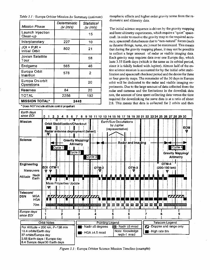
Table 3. I : Europa Orbiter Mission Av Summary (estimate)
Deterministic Statistical Mission Phase Av (ds ) Av ( d s ) Launch Injection Clean-up 15
I
Tour
Endgame
Insertion Europa Orbit
46 565
578 2
Europa On-orbit Operations 20
Reserves a4 20 TOTAL
2448 MISSION TOTAL* 2256 I 192
I I I * Does NOTinclude attitude control propellant
mospheric effects and higher order gravity terms from the ra- diometric and altimetry data.
The initial science sequence is driven by the gravity mapping and laser altimetry experiments, which require a “quiet” space- craft. In order to resolve the gravity map to the required accu- racy, spacecraft disturbances due to “non-natural” forces (such as thruster firings, turns, etc.) must be minimized. This means that during the gravity mapping phase, it may not be possible to collect a large amount of radar or visible imaging data. Each gravity map requires data over one Europa day, which lasts 3.55 Earth days (which is the same as its orbital period, since it is tidally locked with Jupiter). Almost half of the en- tire science mission is accounted for by the initial orbit stabi- lization and spacecraft checkout period and the desire for three or four gravity maps. The remainder of the 30 days in Europa orbit will be dedicated to the radar and visible imaging ex- periments. Due to the large amount of data collected from the radar and cameras and the limitations in the downlink data rate, the amount of time spent collecting data versus the time required for downlinking the same data is at a ratio of about 2:8. This means that data is collected for 2 orbits and then
Figure 3.3 : Europa Orbiter Science Mission Timeline (example)
downlinked during the next 8 orbits. The downlinking strat- egy must also account for Europa occultations (once every orbit for about 45 minutes, depending on altitude and geom- etry) and Jupiter occultations (once every Europa day for about 3 hours) of the Earth which prohibit communications.
An example of a science mission timeline is shown in Figure 3.3. It is likely that some science data will be collected before the spacecraft is inserted into Europa orbit, particularly radar and imaging during the tour and endgame flybys of Europa (and possibly even other Jovian satellites). This will provide time to calibrate and test instruments, but should also result in useful scientific data.
Launch System- The selection of a launch system for the Europa Orbiter mission is driven by several issues, including spacecraft mass, launch energy requirements, safety, reliabil- ity, and available budget. Due to the high launch energy re- quirement (driven by the direct interplanetary trajectory) and large spacecraft mass (driven by the propulsion system and large Av requirement), the proposed launch system for use as a baseline for the current spacecraft and mission design is the Space Shuttle (STS or Space Transportation System). The STS would carry the spacecraft along with an IUS (Inertial Upper Stage) and a Star-48V kick stage into orbit for release and injection onto the direct interplanetary transfer.
Spacecraft Design .
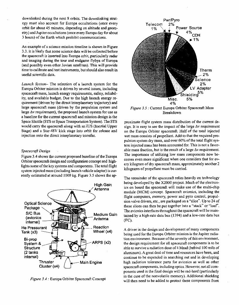
Figure 3.4 shows the current proposed baseline of the Europa Orbiter spacecraft design and configuration concept and high- lights some of the key systems and components. The total flight system injected mass (including launch vehicle adapter) is cur- rently estimated at around 1000 kg. Figure 3.5 shows the ap-
High Gain Antenna
(avionics 1 internal) m
He Pressurant Tank (x3) 1 Wheel (x4)
b - Reaction
Bi-prop System & ARPS ( x 2 ) Structure (2 tanks internal)
Thruster Cluster (x4) 0- Main Engine
Figure 3.4 : Europa Orbiter Spacecraft Concept
PwdPyro Telecom 2%
I OL \ I Power Source
Misc. 5% 4 yo
Figure 3.5 : Current Europa Orbiter Spacecraft Mass Breakdown
proximate flight system mass distribution of the current de- sign. It is easy to see the impact of the large Av requirement on the Europa Orbiter spacecraft. Half of the total injected wet mass consists of propellant. Add to that the required pro- pulsion system dry mass, and over 60% of the total flight sys- tem injected mass has been accounted for. This is not a favor- able mass fraction, but is the result of a large Av requirement. The importance of utilizing low mass components now be- comes even more significant when one considers that for ev- ery kilogram of dry spacecraft mass, approximately another 2 kilograms of propellant must be-canied.
The remainder of the spacecraft relies heavily on technology being developed by the X2000 project. Much of the electron- ics on board the spacecraft will make use of the rnulti-chip module (MCM) concept. Spacecraft avionics, including the flight computers, memory, power and pyro control, propul- sion valve drivers, etc., are packaged on a “slice”. Up to 24 of these slices can then be put together into a “stack” or “loaf’. The avionics interfaces throughout the spacecraft will be main- tained by a high-rate data bus (1 394) and a low-rate data bus ( I T ) .
A driver in the design and development of many components being used for the Europa Orbiter mission is the Jupiter radia- tion environment. Because of the severity of this environment, the design requirement for all spacecraft components is to be able to survive a radiation dose of 4 Mrad (behind 100 mils of aluminum). A great deal of time and resources have been, and continue to be expended in searching out and in developing high radiation tolerance parts for avionics as well as other spacecraft components, including optics. However, not all com- ponents used in the final design will be rad-hard (particularly in the case of the nonvolatile memory). Additional shielding will then need to be added to protect these components from
the radiation environment. It is obvious that there is a great desire to minimize this additional shielding mass. This shield- ing is “dead mass”. It serves no useful purpose other than to protect those rad-soft parts and, as a consequence of the added mass, forces the spacecraft to cany additional propellant.
Mass is not the only critical resource on the Europa Orbiter spacecraft. Power is another resource which must be managed carefully. Although the spacecraft makes use of the lowest power components available which can do the job, sufficient power must be provided during the entire mission to support all spacecraft operations, particularly the science mission. Due to the distance from the Sun during this time, the frequent solar occultations by Europa (once per orbit) and by Jupiter (once per Europa day), the spacecraft must be supplied with continuous power. Although the final design decisions have not yet been made, the current proposed baseline makes use of the Advanced Radioisotope Power Source ( A R P S ) . To- gether, two of these provide the spacecraft with approximately 200 W by the end of mission (which is about one fourth of what is required for the Cassini spacecraft). A secondary bat- tery may also be used to compensate for short duration andor transient power loads.
Communications to and from the spacecraft will be at X-band. The telecommunications subsystem consists of a 2 m High Gain Antenna (HGA), the Small Deep Space Transponder (SDST), an X-band Solid State Power Amplifier (X-SSPA), and supporting equipment. A Medium Gain Antenna (MGA), which will make use of an articulating mirror to steer the ra- dio beam, will be used for the gravity mapping phase of the Europa Orbiter science mission in order to maintain a com- munications link for acquiring tracking data. Downlinking of other science and engineering data will be accomplished by turning the spacecraft so that the HGA points at Earth. The HGA provides the added benefit of acting as a solar shade to the spacecraft while it is still within the inner solar system.
The October 1998 baseline design for the propulsion sub- system consists of a two tank, dual-mode system. A bi-propel- lant main engine, with a thrust on the order of 450 N and an Isp of around 325 sec., will be used for all deterministic as well as the larger statistical maneuvers. Additional 22 N mono- propellant thrusters (which utilize the same hydrazine as the bi-propellant main engine) are used for the smaller statistical maneuvers as well as for thrust vector control during the main engine bums. These thrusters will also provide roll control during the Star-48V kick stage bum at launch. Management of the propellant to the thrusters will be controlled by a Vari- able Liquid Regulator (VLR) developed by X2000. This com- ponent will provide better feedback between upstream pres- sure in the propellant tanks and downstream pressure at the thruster or engine, thus providing enhanced performance.
Attitude determination is accomplished using a sun sensor, star tracker, and an Inertial Measurement Unit (IMU). The
sun sensor will provide initial and emergency, coarse attitude determination, while the star tracker will provide more refined attitude determination. The IMU package includes gyros which will provide 3-axis propagation of attitude whenever turn rates exceed the capability of the star tracker. The IMU also in- cludes a single axis accelerometer that will be used to time- cutoff spacecraft main engine bums. Fine attitude control will be performed using three Reaction Wheels (RWs). There is one spare wheel that will be mounted so that it can compen- sate for the loss of any of the other three wheels. Coarse con- trol, as well as momentum dumping of the RWs, will be per- formed using the 22 N thrusters.
As discussed earlier, the actual science payload for the Europa Orbiter mission will not be selected until mid- 1999. Currently, a strawman payload is being used to assist in the early space- craft design phase. This consists of a wide angle camera, a narrow angle camera, a laser altimeter, and an ice penetrating radar. All of the optical instruments will be packaged together and mounted to the spacecraft, along with the radar antenna which is deployed after launch. The science instrument elec- tronics may utilize the MCM concept from X2000 and, there- fore, could be packaged along with the spacecraft avionics.
The main spacecraft bus consists of 4 main structural panels and 4 smaller connector panels. These composite panels will also be developed by X2000, and not only provide structure for mounting the avionics and other equipment, but also con- sist of embedded cabling to provide cleaner connections be- tween the avionics components themselves as well as to the rest of the spacecraft. The electronics are all housed within this bus structure in an attempt to provide additional radia- tion shielding. The optical instruments and trackers, antenna, RWs, and thermal control components (i.e. louvers) are mounted to the exterior of the bus structure. Support is also provided by the propulsion system structure, which houses the propellant tanks, and provides mounting for the Helium pressurant tanks, the ARPSs, the main engine, the thruster clus- ters, the radar antenna, etc. Thermal control of the spacecraft, including the propulsion system, is currently planned to be provided solely by waste heat from the power sources, with the exception of the thruster clusters where the lines and thrust- ers themselves may be kept warm by use of small Radioiso- tope Heater Units (RHUS).
The entire spacecraft is then integrated to the launch system by way of the launch vehicle adapter. This will provide the mechanical and electrical interface and provide the proper load path from the launch system to the spacecraft.
As discussed earlier, the Europa Orbiter mission, as well as the other OP/SP missions, will make use of the new ground and flight data system development by MDS, which will fur- ther lower development costs. Utilizing MDS will also allow for minimization of mission operations costs by the sharing of resources across multiple missions.
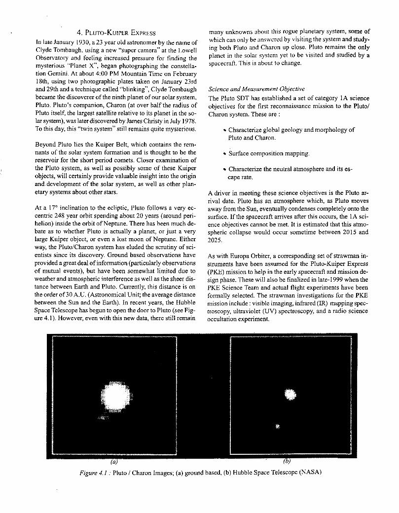
4. PLUTO-KUIPER EXPRESS In late January 1030, a 23 year old astronomer by the name of Clyde Tombaugh, using a new “super camera” at the Lowell Observatory and feeling increased pressure for finding the mysterious “Planet X”, began photographing the constella- tion Gemini. At about 4:OO PM Mountain Time on February 18th, using two photographic plates taken on January 23rd and 29th and a technique called “blinking”, Clyde Tombaugh became the discoverer of the ninth planet of our solar system, Pluto. Pluto’s companion, Charon (at over half the radius of Pluto itself, the largest satellite relative to its planet in the so- lar system), was later discovered by James Christy in July 1978. To this day, this “twin system” still remains quite mysterious.
Beyond Pluto lies the Kuiper Belt, which contains the rem- nants of the solar system formation and is thought to be the reservoir for the short period comets. Closer examination of the Pluto system, as well as possibly some of these Kuiper objects, will certainly provide valuable insight into the origin and development of the solar system, as well as other plan- etary systems about other stars.
At a 17’ inclination to the ecliptic, Pluto follows a very ec- centric 248 year orbit spending about 20 years (around peri- helion) inside the orbit of Neptune. There has been much de- bate as to whether Pluto is actually a planet, or just a very large Kuiper object, or even a lost moon of Neptune. Either way, the PlutoICharon system has eluded the scrutiny of sci- entists since its discovery. Ground based observations have provided a great deal of information (particularly observations of mutual events), but have been somewhat limited due to weather and atmospheric interference as well as the sheer dis- tance between Earth and Pluto. Currently, this distance is on the order of 30 A.U. (Astronomical Unit; the average distance between the Sun and the Earth). In recent years, the Hubble Space Telescope has begun to open the door to Pluto (see Fig- ure 4.1). However, even with this new data, there still remain
many unknowns about this rogue planetary system, some of which can only be answered by visiting the system and study- ing both Pluto and Charon up close. Pluto remains the only planet in the solar system yet to be visited and studied by a spacecraft. This is about to change.
Science and Measurement Objective The Pluto SDT has established a set of category 1A science objectives for the first reconnaissance mission to the Pluto/ Charon system. These are :
Characterize global geology and morphology of Pluto and Charon.
Surface composition mapping.
Characterize the neutral atmosphere and its es- cape rate.
A driver in meeting these science objectives is the Pluto ar- rival date. Pluto has an atmosphere which, as Pluto moves away from the Sun, eventually condenses completely onto the surface. If the spacecraft arrives after this occurs, the 1A sci- ence objectives cannot be met. It is estimated that this atmo- spheric collapse would occur sometime between 201 5 and 2025.
As with Europa Orbiter, a corresponding set of strawman in- struments have been assumed for the Pluto-Kuiper Express (PKE) mission to help in the early spacecraft and mission de- sign phase. These will also be finalized in late- 1999 when the PKE Science Team and actual flight experiments have been formally selected. The strawman investigations for the PKE mission include : visible imaging, infrared (IR) mapping spec- troscopy, ultraviolet (UV) spectroscopy, and a radio science occultation experiment.
Meeting these measurement objectives will be a real challenge. Unlike the Europa Orbiter mission, Pluto-Kuiper Express is a fast flyby through the Pluto/Charon system. The spacecraft observations of the system will exceed the best Hubble im- ages when the spacecraft is still weeks from the encounter. The encounter scenario in which the primary science is to be collected is on the order of 5 hours, during which all science data required to meet the 1A science objectives must be col- lected .
Mission Design As with Europa Orbiter, the Pluto-Kuiper Express mission design is also driven by flight time and launch system capa- bility. Pluto sits at the edge of our solar system, not within easy reach. Many trajectory options are available, between direct to Pluto, and those utilizing single or multiple planetary gravity assists. Given the fact that any choice will likely result in a relatively long flight time to Pluto, the hope is to mini- mize this effect while at the same time minimizing both the launch energy and mission Av (and, thus, spacecraft mass) requirements.
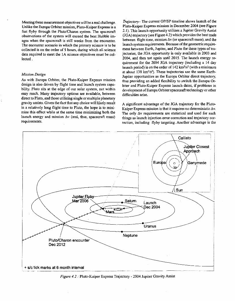
Trajectoty- The current OP/SP timeline shows launch of the Pluto-Kuiper Express mission in December 2004 (see Figure 2.1). This launch opportunity utilizes a Jupiter Gravity Assist (JGA) trajectory (see Figure 4.2) which provides the best trade between flight time, mission Av (or spacecraft mass), and the launch system requirements. Because of the geometric require- ment between Earth, Jupiter, and Pluto for these types of tra- jectories, the JGA opportunity is only available in 2003 and 2004, and then not again until 2015. The launch energy re- quirement for the 2004 JGA trajectory (including a 14 day launch period) is on the order of 142 km2/s2 (with a minimum at about 138 kmz/s2). These trajectories use the same Earth- Jupiter opportunities as the Europa Orbiter direct trajectory, thus providing an added flexibility to switch the Europa Or- biter and Pluto-Kuiper Express launch dates, if problems in development of Europa Orbiter spacecraft technology or other difficulties arise.
A significant advantage of the JGA trajectory for the Pluto- Kuiper Express mission is that it requires no deterministic Av. The only Av requirements are statistical and used for such things as launch injection error correction and trajectory cor- rection, including flyby targeting. Another advantage is the
.............................................................. x ~ ...... ~ .- ...........
Uranus
\ -
Neptune Pluto/Charon Dec 201 2
+ slc tick marks at 6 month interval
” \ Figure 4.2 : Pluto-Kuiper Express Trajectory - 2004 Jupiter Gravity Assist
flexibility it provides in the spacecraft design. A clear trade between the flight time to Pluto and the spacecraft mass can be used. This is done using a relationship in which the flight system mass is translated into a maximum possible launch energy, given a specific launch system, which in turn deter- mines the flight time to Pluto. The current spacecraft design results in a system mass which would allow for an 8 year flight time to Pluto for the 2004 JGA opportunity.
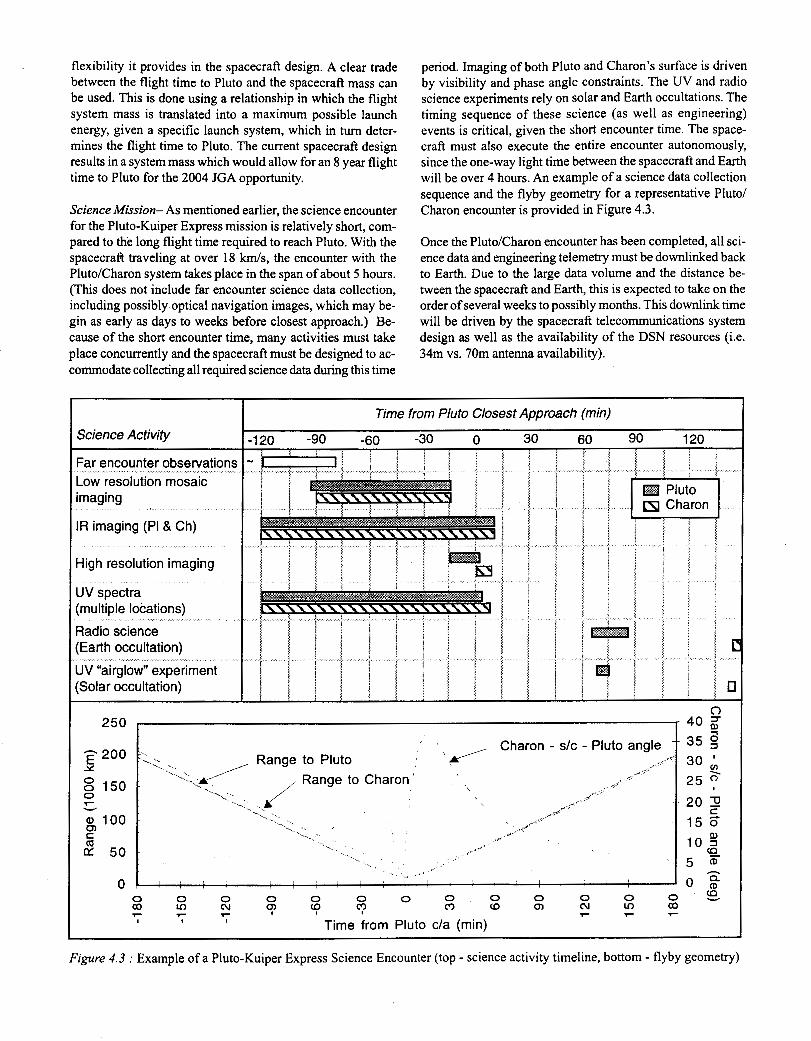
Science Mission- As mentioned earlier, the science encounter for the Pluto-Kuiper Express mission is relatively short, com- pared to the long flight time required to reach Pluto. With the spacecraft traveling at over 18 km/s, the encounter with the Pluto/Charon system takes place in the span of about 5 hours. (This does not include far encounter science data collection, including possibly optical navigation images, which may be- gin as early as days to weeks before closest approach.) Be- cause of the short encounter time, many activities must take place concurrently and the spacecraft must be designed to ac- commodate collecting all required science data during this time
period. Imaging of both Pluto and Charon's surface is driven by visibility and phase angle constraints. The UV and radio science experiments rely on solar and Earth occultations. The timing sequence of these science (as well as engineering) events is critical, given the short encounter time. The space- craft must also execute the entire encounter autonomously, since the one-way light time between the spacecraft and Earth will be over 4 hours. An example of a science data collection sequence and the flyby geometry for a representative Pluto/ Charon encounter is provided in Figure 4.3.
Once the Pluto/Charon encounter has been completed, all sci- ence data and engineering telemetry must be downlinked back to Earth. Due to the large data volume and the distance be- tween the spacecraft and Earth, this is expected to take on the order of several weeks to possibly months. This downlink time will be driven by the spacecraft telecommunications system design as well as the availability of the DSN resources (Le. 34m vs. 70m antenna availability).
Science Activity
'ar encounter observations -ow resolution mosaic maging
R imaging (PI & Ch)
4igh resolution imaging
UV spectra [multiple locations) Radio science :Earth occultation) JV "airglow" experiment :Solar occultation)
I Time from Pluto Closest Approach (min) -120 -90 -60 -30 0 30 60 90 120
Figure 4.3 : Example of a Pluto-Kuiper Express Science Encounter (top - science activity timeline, bottom - flyby geometry)
Launch Sysfem- As with the Europa Orbiter mission, the launch system selection for the Pluto-Kuiper Express mission is driven not only by spacecraft and mission constraints, but also pro- grammatic considerations. As mentioned earlier, the launch system capability requirement stems directly from the desired flight time. This, in tum, provides the maximum spacecraft system mass allowable. Another way to look at it is given the spacecraft system mass, the launch system requirement is de-
, termined, and thus the flight time to Pluto.
The proposed PKE launch system concept includes two pos- sibilities: the STS/IUS/Star-48V (the same launch system be- ing used for the Europa Orbiter baseline), and an expendable launch vehicle (ELV) of Delta I11 “class”, with a Star-48V kick stage. With the current spacecraft system design, each of these launch systems provides sufficient performance for an 8 year flight time to Pluto. The Space Shuttle option provides sufficient injected mass margin for this trajectory, and allows for added flexibility in spacecraft mass without significant im- pact to the flight time. Another added benefit is that this op- tion is, in fact, identical launch system, and thus provides very similar launch system interfaces, as that currently baselined for the Europa Orbiter mission. The ELV options do provide for an 8 year flight time with the current spacecraft mass. However, they do not provide as much performance margin as the Space Shuttle option and any significant increase in the spacecraft mass would quickly impact the flight time to Pluto.
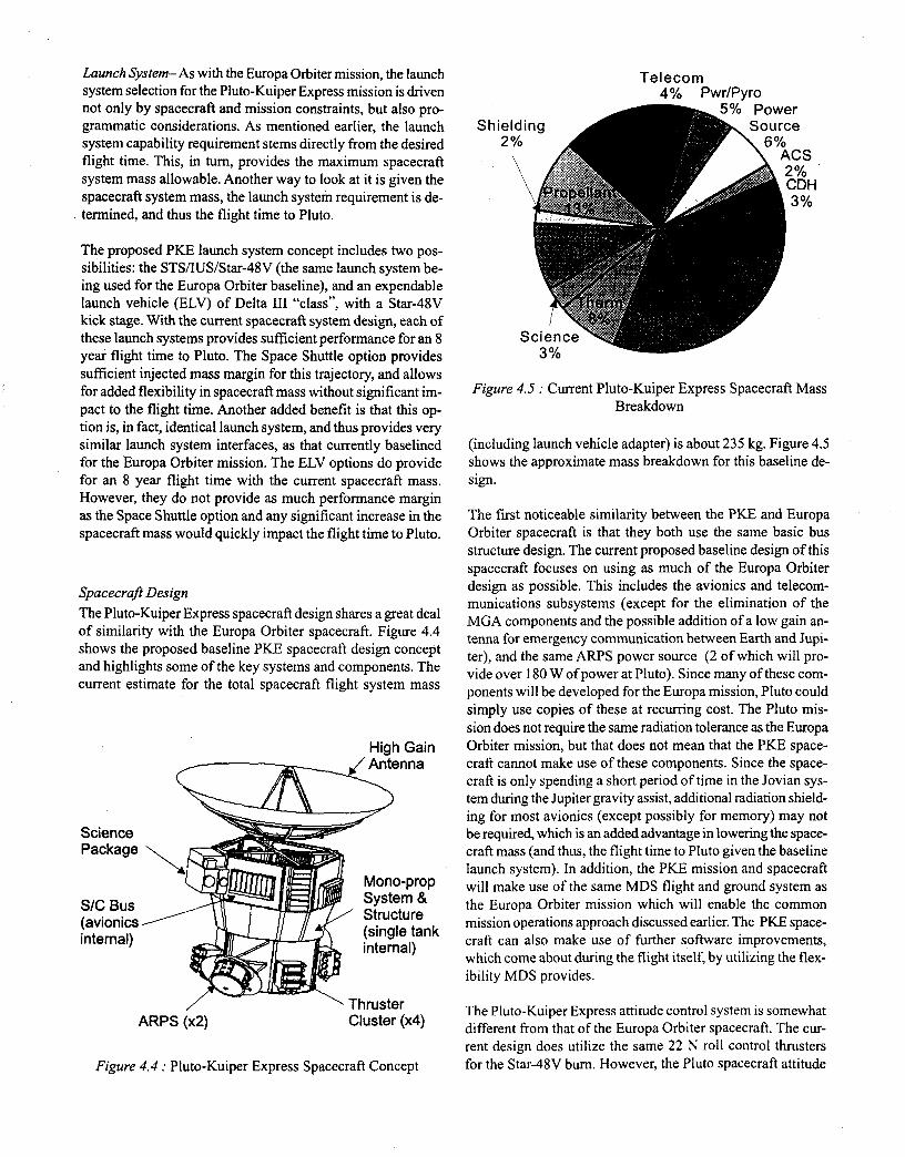
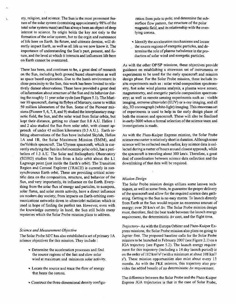
Spacecraft Design The Pluto-Kuiper Express spacecraft design shares a great deal of similarity with the Europa Orbiter spacecraft. Figure 4.4 shows the proposed baseline PKE spacecraft design concept and highlights some of the key systems and components. The current estimate for the total spacecraft flight system mass
High Gain
Science Package
SIC Bus (avionics internal)
/ Thruster ARPS (x2) Cluster (x4)
Figure 4.4 : Pluto-Kuiper Express Spacecraft Concept
Shie 2
S
Telecom 4 Yo PwrIPvro
Figure 4.5 : Current Pluto-Kuiper Express Spacecraft Mass Breakdown
(including launch vehicle adapter) is about 235 kg. Figure 4.5 shows the approximate mass breakdown for this baseline de- sign.
The first noticeable similarity between the PKE and Europa Orbiter spacecraft is that they both use the same basic bus structure design. The current proposed baseline design of this spacecraft focuses on using as much of the Europa Orbiter design as possible. This includes the avionics and telecom- munications subsystems (except for the elimination of the MGA components and the possible addition of a low gain an- tenna for emergency communication between Earth and Jupi- ter), and the same A R P S power source (2 of which will pro- vide over 180 W ofpower at Pluto). Since many of these com- ponents will be developed for the Europa mission, Pluto could simply use copies of these at recurring cost. The Pluto mis- sion does not require the same radiation tolerance as the Europa Orbiter mission, but that does not mean that the PKE space- craft cannot make use of these components. Since the space- craft is only spending a short period of time in the Jovian sys- tem during the Jupiter gravity assist, additional radiation shield- ing for most avionics (except possibly for memory) may not be required, which is an added advantage in lowering the space- craft mass (and thus, the flight time to Pluto given the baseline launch system). In addition, the PKE mission and spacecraft will make use of the same MDS flight and ground system as the Europa Orbiter mission which will enable the common mission operations approach discussed earlier. The PKE space- craft can also make use of further software improvements, which come about during the flight itself, by utilizing the flex- ibility MDS provides.
The Pluto-Kuiper Express attitude control system is somewhat different from that of the Europa Orbiter spacecraft. The cur- rent design does utilize the same 22 N roll control thrusters for the Star-48V bum. However, the Pluto spacecraft attitude

c o ~ ~ t r o l t x l s c l ~ ~ ~ c tlocs 1 1 0 1 ~llakc use 0 1 ' reactloll \\,I~ccls. b u t illstc;d tlscs aI11;IIIcr Illrtatct-s. 'l'llc trade study i l l 1111s ;IK;I con- tinues, x n t l current possihle solutions inclL1cle usillg 0 . 0 N thrtlstcrs li)r coursc attitude control :Ind evcI1 snullcr InN thrustera (possibly clcvelopcd by X7000) o r a ~v;1r tn gas thrustct systcm for right attitude control during the Plutoi'Charon en- counter. I t is also likely that the PKE spacecraft will use very different star trackers. For the Europa Orbiter mission, the design of the star tracker is driven by the radiation environ- ment. I t is possible that the PKE mission can make use of much simpler, off-the-shelf equipment to gain the required performance.
The most noticeable difference between the two spacecraft designs is in the propulsion system. Since the Pluto-Kuiper Express mission does not have the same tremendous Av re- quirement that the Europa Orbiter spacecraft must accommo- date, only a small mono-propellant propulsion system is re- quired. The PKE mission Av requirement can be accomodated using a single, hydrazine tank and the attitude control thrust- ers.
Another obvious difference in the Europa Orbiter and Pluto- Kuiper Express spacecraft is in the science payload. The PKE
str;1wnlaIl p y I o : ~ d IllcIucIcs ;I V I S I I ~ I ~ ~lllagcr. x 1 I R imager, an ul t rav io le t spcctrorllctcr. ; 1 n d ; d c l i ~ i o t w l ccluiplncnt in the tele- comlnllnie~ltiorls subsystem (including an ultra-stable oscilla- t o r ) t o ;Icconllnodate the radio science experiments. The mount- Ing ot'thcsc irlstrumcnts IS also still under study. The driving requirement here IS the collrctlon of the required science data at the deslred resolution 'IS the spacecraft passes through the Pluto/Charon system. If it turns out that the spacecraft cannot provlde the required slew rate and stability, some sort of scan- ning platform or scan mirrors may be required to insure the instruments can properly collect all of the science data.
All In all, as mentioned earlier, the Pluto-Kuiper Express space- craft design is centered on making use of as much from the Europa Orbiter spacecraft as possible; from the component level to entire subsystems. With this approach, many compo- nents can be purchased at recurring cost, thus, the spacecraft development costs are kept at a minimum. This, however, will not increase risk or compromise performance of the PKE spacecraft or mission.
5. SOLAR PROBE The Sun has always been a key central theme in human soci-
Figure) 5. I . ' Composlte of 12 solar images showing the variability o f the Sun through a portion of the solar cycle; taken at 90 day Interval by the Yohkoh spacecraft w n g an x-ray imager (ISAS/NASA)
ety, religion, and science. The Sun is the most prominent fea- ture of the solar system (containing approximately 98% of the total solar system mass) and has always been an object of deep interest to science. Its origin holds the key not only to the formation of the solar system, but to the orgin and sustenance of life here on Earth. Its future, and ultimate demise, will di- rectly impact Earth, as well as all life as we now know it. The importance of understanding the Sun’s past, present, and h- ture, and the level at which it interacts and influences life here on Earth cannot be overstated.
There has been, and continues to be, a great deal of research on the Sun, including both ground based observation as well as space based exploration. Due to the harsh environment in close proximity to the Sun, this work has been limited to rela- tively distant observations. These have provided a great deal of information about structure of the Sun and its behavior dur- ing the roughly 1 1 year solar cycle (see Figure 5.1). The Mari- ner 10 spacecraft, during its flybys of Mercury, came to within 50 million kilometers of the Sun. Some of the Pioneer mis- sions (Pioneer 5,6,7,8, and 9) studied the interplanetary mag- netic field, the Sun, and the solar wind from Solar orbits, but kept their distance, getting no closer that 0.8 A.U. Helios 1 and 2 also studied the Sun from solar orbit, with closest ap- proach of under 45 million kilometers (0.3 A.U.). Earth or- biting observations of the Sun have included Skylab, Helios 1A and lB, the Solar Maximum Mission (SMM), and theYohkoh spacecraft. The Ulysses spacecraft, which is cur- rently studying the Sun in a heliocentric polar orbit, has a peri- helion of 1.3 A.U. The Solar and Heliospheric Observatory (SOHO) studies the Sun from a halo orbit about the L1 Lagrange point (just inside the Earth’s orbit). The Transition Region and Coronal Explorer (TRACE) is currently in sun- synchronous Earth orbit. These are providing critical scien- tific data on the composition, structure, and behavior of the Sun, and very importantly, its influence on the Earth. Every- thing from the solar flux of energy and particles, to sunspots, solar flares, and solar storm activity, have a direct influence on modem day society; from impacts on Earth-orbiting com- munications networks down to ultraviolet radiation which is used in hope of finding the perfect tan. However, even with the knowledge currently in hand, the Sun still holds many mysteries which the Solar Probe mission plans to address.
Science and Measurement Objective The Solar Probe SDT has also established a set of primary 1 A science objectives for this mission. They include :
Determine the acceleration processes and find the source regions of the fast and slow solar wind at maximum and minimum solar activity.
Locate the source and trace the flow of energy that heats the corona.
Construct the three-dimensional density configu-
ration from pole to pole; and determine the sub- surface flow pattern, the structure of the polar magnetic field, and its relationship with the over- lying corona.
Identify the acceleration mechanisms and locate the source regions of energetic particles, and de- termine the role of plasma turbulence in the pro- duction of solar wind and energetic particles.
As with the other OP/SP missions, these objectives provide guidance on establishing a strawman set of instruments or experiments to be used for the early spacecraft and mission design phase. For the Solar Probe mission, these include in- situ experiments such as : solar wind composition spectrom- etry, fast solar wind plasma analysis, a plasma wave sensor, magnetometry, and energetic particle composition spectrom- etry; as well as remote sensing experiments such as : visible imaging, extreme ultraviolet (EUV) or x-ray imaging, and all sky, 3D coronagraph (white-light) imaging. This strawman set of experiments is used to help in the early design phase of both the mission and spacecraft. These will also be finalized in early-2000 when a formal selection of the science team and investigations is made.
As with the Pluto-Kuiper Express mission, the Solar Probe science encounter is relatively short in duration. Although some science will be collected much earlier, key science data is col- lected during a matter of hours around closest approach, while the spacecraft is traveling about 300 km/s. Therefore, a great deal of coordination between science data collection and the downlinking of that data will be required.
Mission Design The Solar Probe mission design utilizes some known tech- niques, as well as some firsts, to guarantee the proper delivery of the spacecraft and allow for the required science data gath- ering. Getting to the Sun is no easy matter. To launch directly from Earth at the Sun would require an enormous amount of energy; over 20 km/s of Av. The Solar Probe mission design must, therefore, find the best trade between the launch energy requirement, the deterministic Av cost, and the flight time.
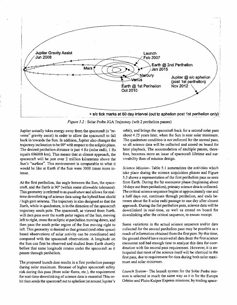
Trajectory- As with the Europa Orbiter and Pluto-Kuiper Ex- press missions, the Solar Probe mission also plans on going to Jupiter first. The proposed baseline calls for the Solar Probe mission to be launched in February 2007 (see Figure 2.1) on a JGA trajectory (see Figure 5.2). The launch energy require- ment for this trajectory (including a 14 day launch period) is on the order of 1 12 km’/s2 (with a minimum at about 108 k m 2 /
s2). These mission opportunities also exist about every 13 months. As with the PKE mission, this trajectory also pro- vides the added benefit of no deterministic Av requirement.
The difference between the Solar Probe and the Pluto-Kuiper Express JGA trajectories is that in the case of Solar Probe,
I .... + s/c tick marks at 60 day interval (out to aphelion post 1st perihelion only) .................................................................. .........................................................................................................................................................................
Figure 5.2 : Solar Probe JGA Trajectory (wth 2 perihelion passes)
Jupiter actually takes energy away from the spacecraft (a “re- verse’’ gravity assist) in order to allow the spacecraft to fall back in towards the Sun. In addition, Jupiter also changes the trajectory inclination to be 90” with respect to the ecliptic plane. The desired perihelion distance is just 4 Rs (solar radii; 1 Rs equals 696000 km). This means that at closest approach, the spacecraft will be just over 2 million kilometers above the Sun’s “surface”. This environment is comparable to what it would be like at Earth if the Sun were 3000 times more in- tense.
At the first perihelion, the angle between the Sun, the space- craft, and the Earth is 90” (within some allowable tolerance). This geometry is referred to as quadrature and allows for real- time downlinking of science data using the hybrid heat shield I high gain antenna. The trajectory is also designed so that the Earth, while in quadrature, is in the direction of the spacecraft trajectory south pole. The spacecraft, as viewed from Earth, will then pass over the north polar region of the Sun, moving left to right, cross the ecliptic at perihelion moving down, and then pass the south polar region of the Sun moving right to left. This geometry is desired so that ground (and other space) based observations of solar activity can be coordinated and compared with the spacecraft observations. A longitude on the Sun can first be observed and studied from Earth shortly before that same longitude rotates under the spacecraft as it passes through perihelion.
The proposed launch date results in a first perihelion passage during solar maximum. Because of higher spacecraft safety risk during this pass (from solar flares, etc.), the requirement for real-time downlinking of science data is essentiaLThis or- bit then sends the spacecraft out to aphelion (at around Jupiter’s
orbit), and brings the spacecraft back for a second solar pass about 4.25 years later, when the Sun is near solar minimum. The quadrature condition is not enforced for the second pass, so all science data will be collected and stored on board for later playback. The accomodation of multiple passes, there- fore, becomes more an issue of spacecraft lifetime and sur- vivability than of mission design.
Science Mission- Table 5.1 summarizes the activities which take place during the science acquisition phases and Figure 5.3 shows a representation of the first perihelion pass as seen from Earth. During the far encounter phase (beginning about 10 days out from perihelion), primary science data is collected. The critical science sequence begins at approximately one and a half days out, continues through perihelion, and ends be- tween about the 8 solar radii passage to one day after closest approach. During the fist perihelion pass, science data will be downlinked in real-time, as well as stored on board for downlinking after the critical sequence, to ensure receipt.
Some variations in the actual science sequence and/or data collected for the second perihelion pass may be possible as a result of information obtained from the first pass. By this time, the ground should have received all data from the first science encounter and had enough time to analyze this data for coor- dination with the second pass requirement. However, it is an- ticipated that most of the science itself will be identical to the first pass, due to requirement for data during both solar maxi- mum and solar minimum.
Launch System- The launch system for the Solar Probe mis- sion is selected in much the same way as it is for the Europa Orbiter and Pluto-Kuiper Express missions; by trading space-
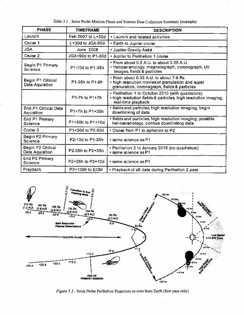
Table 5.1 : Solar Probe Mission Phase and Science Data Collection Summary (example)
PHASE DESCRIPTION TIMEFRAME Launch
Jupiter to Perihelion 1 cruise JGA+SOd to P130d Cruise 2 Jupiter Gravity A s 4 3 June 2008 JGA Earth to Jupitercmise L+30d to JGA-9Od Cruise 1 Launch and related activities Feb 2007 to L+30d
From about 0.5 A.U. to about 0.35 A.U. Science Begin Primary Helioseismology, magnetograph, coronograph, UV pq-lod to p1-35h
images, fields & particles
Begin P1 Critical Data Aquisition
From about 0.35 A.U. to about 7-8 Rs PI-35h to P1-8h high resolution movies of granulation and super
granulation, coronagraph, fields & particles Perihelion 1 in October 2010 (with quadrature)
PI-7h to P1+7h high resolution fields& particles, high resolution imaging, real-time playback
End PI Critical Data Aquisition
fields and particles, high resolution imaging, begin P1+7h to P1+35h downlinldng of data
End PI Primary fieldsand particles, high resolution imaging, possible Science P1+35h to Pl+lOd helioseismology, contiue downlinldng data Cnrise 3 P1+30d to P2-30d Cruise from PI to aphelion to P2 Begin P2 Primary Science P2-1Od to PI-35h same science a s PI
Begin P2 Critical Perihelion 2 in January 2015 (no quadrature) Data Aquisition P2-35h to P2+35h Same science as p1 End P2 Primary Science I P2+35h to P2+10d I Same science asp1 Playback I P2+106h to EOM I Playbackof all data during Perihelion 2 pass
Figure 5.3 : Solar Probe Perihelion Trajectory as seen from Earth (first pass only)
craft mass with launch system performance and cost. How- ever, in the case of Solar Probe, the flexibility in changing the flight time using the JGA trajectory does not exist as it does for the PKE mission. Here, the launch energy required to reach Jupiter with a velocity such that Jupiter’s “reverse” gravity assist sends the spacecraft back towards the Sun is a relatively constant value (although small variations due to the eccen- tricity of Earth and Jupiter’s orbit do exist). This means that the launch system selection is based on finding a vehicle with sufficient lift performance given the Solar Probe spacecraft system mass, which also fits within the project funding con- straints. For the Solar Probe mission, the current proposed baseline launch system is an ELV, Delta I11 “class”, with a Star-48V kick stage. A launch vehicle of this class should be able to provide sufficient performance (with margin) for the Solar Probe mission. If the Pluto-Kuiper Express mission also utilizes the ELV option, this would mean that identical launch systems, as well as very similar launch system interfaces, would be used for these two missions.
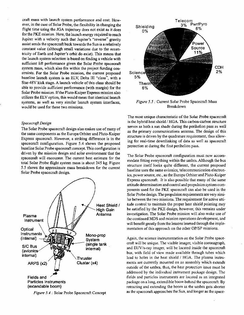
spacecraft Design The Solar Probe spacecraft design also makes use of many of the same components as the Europa Orbiter and Pluto-Kuiper Express spacecraft. However, a striking difference is in the spacecraft configuration. Figure 5.4 shows the proposed baseline Solar Probe spacecraft concept. This configuration is driven by the mission design and solar environment that the spacecraft will encounter. The current best estimate for the total Solar Probe flight system mass is about 245 kg. Figure 5.5 shows the approximate mass breakdown for the current Solar Probe spacecraft design.
““‘“‘“J Cluster (x4)
Fields and Particles Instruments (extendable boom)
Figure 5.4 : Solar Probe Spacecraft Concept
sc
Sh Telecorn
0% A
r Source \
:ien 5%
1
CDH 2%
6 %
Figure 5.5 : Current Solar Probe Spacecraft Mass Breakdown
The most unique characteristic of the Solar Probe spacecraft is the hybrid heat shield / HGA. This carbon-carbon structure serves as both a sun shade during the perihelion pass as well as the primary communications antenna. The design of this structure is driven by the quadrature requirement, thus allow- ing for real-time downlinking of data as well as spacecraft protection at during the first perihelion pass.
The Solar Probe spacecraft configuration must now accom- modate fitting everything within the umbra. Although the bus structure itself looks quite different, the current proposed baseline uses the same avionics, telecommunication electron- ics, power source, etc., as the Europa Orbiter and Pluto-Kuiper Express spacecraft. It is also possible that many of the same attitude determination and control and propulsion system com- ponents used for the P I E spacecraft can also be used in the Solar Probe design. The propulsion requirements are very simi- lar between the two missions. The requirement for active atti- tude control to maintain the proper heat shield pointing may be satisfied by the PKE design, however, this remains under investigation. The Solar Probe mission will also make use of the continued MDS and mission operations development, and will benefit greatly fiom the lessons learned through the imple- mentation of this approach on the other OP/SP missions.
Again, the science instrumentation on the Solar Probe space- craft will be unique. The visible imager, visible coronagraph, and EUVix-ray imager, will be located inside the spacecraft bus, with field of view made available through tubes which lead to holes in the heat shield / HGA. The plasma instru- ments are currently mounted on an assembly which extends outside of the umbra, thus, the heat protection issue must be addressed by the individual instrument package design. The fields and particles instruments are located as an integrated package on a long, extendible boom behind the spacecraft. By retracting and extending the boom as the umbra gets shorter as the spacecraft approaches the Sun, and longer as the space-

craft moves away, this design allows the instruments to have the best field of view around the spacecraft during the entire encounter. Keep in mind, however, that this design incorpo- rates only the strawman payload. Once the final science in- vestigations are selected, the spacecraft design and configura- tion will have to be reassessed to insure compatibility.
By attempting to maximize the commonality between all three spacecraft, the hope is that development and manufacturing costs are minimized. The impact of this approach on the Solar Probe spacecraft design is not well known at this time. Due to the much later launch date, most of the focus has been on the Europa Orbiter and Pluto-Kuiper Express spacecraft design, particularly in light of the continued requirement to accom- modate either mission launching in November 2003. Once these designs are understood more completely, focus will be turned to Solar Probe and how to incorporate as much com- monality as possible.
6. SUMMARY The Outer Planets / Solar Probe Project is certainly a very challenging, yet very exciting venture. The days of single, dedicated flight projects, spending several hundreds of mil- lion to billions of dollars to develop large, highly unique space- craft, are at a close. Although each OP/SP mission may con- sists of its own unique scientific and mission characteristics, the similarities between the Europa Orbiter, Pluto-Kuiper Ex- press, and Solar Probe missions will be used to the project’s advantage. Each mission, by focusing on the highest priority science objectives, will attempt to solve a different piece of the mystery surrounding the origin and formation of the solar system and life within it. From the heart of the solar system, the Sun, to the far reaches, Pluto and beyond in the Kuiper Belt, to the search for a suitable environment for extraterres- trial life beneath the surface of the icy Jovian world of Europa, the extreme environments these spacecraft must face will cer- tainly push technology to the limits.
By sharing many of the same avionics and other spacecraft components, the OP/SP project will keep technology devel- opment, as well as recurring costs, low. As three missions in one flight project, which is part of an even larger exploration program, system level as well as project and program level trades can be carried out to share both risk and cost across all of the missions. The X2000 project will continue working to- wards a solution to ensure that state-of-the-art, low mass, low power, and low cost technologies are available for these and future missions. The MDS will revolutionize the approach to flight and ground system development as well as mission op- eration requirements. High commonality even exists in the launch systems under consideration for these three missions. The need for unique development in certain areas may always exist. After all, space exploration is based on the premise of discovery and doing those things that have yet to be done. However, by relying on a central development in those areas of which every mission can make use, and by focusing on
continually improving that central technology base, every mis- sion can benefit, not only by getting the best of what is avail- able, but also by getting it for a lower cost.
Only by working together, as missions in a project, as projects in a program, and as individual programs working towards a common strategic plan, will future space exploration and the continued search into the unknown truly flourish.
7. ACKNOWLEDGMENTS The authors wish to give thanks to the entire Outer Planets / Solar Probe Project team, past, present, and future. The work described here is the result of a team effort, with no single contribution less significant than another. Team members in- clude : John McNamee - Project Manager; Rob Staehle - Deputy Project Manager; Jan Ludwinski, Jennie Johannesen, and Juan Ayon - Mission Design; Alok Chatterjee and Rita Willcoxon - Launch Systems; Rich Terrile - Project Scientist and Pluto science; Torrence Johnson - Europa science; Bruce Tsurutani - Solar Probe science; Paul Henry and Ken Klaasen - Instruments; Jim Randolph - Solar Probe and Technology Development; Shawn Goodman and Alexander Eremenko - Mechanical Systems; Mike Leeds - Propulsion; Rich Kemski and Martin Ratliff - Mission Assurance; Dawn Skinner, James Smith, and Sandy Dawson - Launch Approval; Sue Johnson and Jeff Mellstrom -Attitude Control; Gordon Wood and Bill Moore - Telecommunications; Mark Guman and Chris Potts - Navigation and Orbit Determination; John Carraway - Opera- tions; Anne Elson - Software; Randy Blue - Avionics; Jim Lumsden - Safety; Jackie Giuliano and Richard Shope - Edu- cation and Outreach; Stacy Weinstein - Pluto Express Mis- sion Design; Steve Matousek - Pluto Express Mission Design; Doug Abraham - Pluto Express Launch Approval; Hoppy Price - Pluto Express spacecraft design; and any others we may have forgotten to mention (our sincere apologies). Thanks is also extended to the entire X2000 design and development team, without which, the OP/SP Project could not survive. Special thanks also goes to Stephen Brewster from the OP/SP project for his help in putting this paper together.
The research described in this paper was carried out by the Jet Propulsion Laboratory, California Institute of Technology, under a contract with the National Aeronautics and Space Administration.
8. REFERENCES
The work summarized in this paper is the culmination of years of effort which has resulted in too many references to list here. For firther information and more detail on some of the past and current work within the Outer Planets / Solar Probe Project, see the following references :
Office of Space Science, National Aeronautics and Space Administration, Outer Planets Program Including Europa

I Orbitec Pluto-Kuiper Express, and Solar Probe: Announce- ment of Opportunity, draft version released 1 December 1998.
Staehle, R., et. al., “Ice & Fire Missions to the most Dificult Solar System Destinations ... on a Budget”, IAA-L98-0601, Third IAA International Conference on Low-Cost Planetary Missions, Pasadena, CA, 27 April - 1 May 1998.
Ludwinski, J., et. al., “The Europa Orbiter Mission Design”, IAF 98-4.2.02, 49th International Astronautical Congress, Melboune, Australia, 28 September - 2 October 1998.
Sweetser, T., et. al., “Trajectory Design for a Europa Orbiter Mission: A Plethora of Astrodynamic Challenges”, AAS 97- 174, AASIAIAA Space Flight Mechanics Meeting, Huntsville, AL, 10-12 February 1997.
David H. Levy, Clyde Tombaugh; Discoverer ofplanet Pluto, University of Arizona Press, 1992.
Alan Stem and Jacqueline Mitton, Pluto and Charon; Ice Worlds on the Ragged Edge of the Solar System, John Wiley and Sons, Inc., 1998.
S. A. Stern and D. J. Tholen (editors), Pluto and Charon, Uni- versity o f h z o n a Press, 1997.
Henry, P., et. al., “Exploring the Kuiper Belt: an Extended Pluto Mission”, 2nd IAA Symposium on Realistic Near-Term Advanced Scientific Space Missions, Aosta, Italy, 29 June - 1 July 1998.
Randolph, J. E., et. al., “Innovations on the Solar Probe Mis- sion”, Submitted for publication in the SPIE Journal (article number 3442-02).
Randolph, J. E., (editor), “Solar Probe: Mission and System Design Concepts 1994”, JPL internal document JPL.D- 12396, December 1994.
Randolph, J. E., (editor), “Solar Probe: Mission and System Design Concepts 1997”, JPL internal document JPL D- 15342, December 1997.
Also, please feel free to contact any of the authors for addi- tional information andlor references.
The following websites provide hrther information , as well as links to other resources, on the Outer Planet / Solar Probe Project (including education and outreach resources), as well as other U.S., foreign, and international space exploration ef- forts :
http://www.jpl.nasa.gov/ice-fire http://www.cism.jpl.nasa.gov http://www.jpl.nasa.gov http://www.nasa.gov
http://msl.jpl.nasa.gov http://www,hawastsoc.org/solar
9. ABOUT THE AUTHORS Rob Maddock received his BS in Aerospace Engineering from St. Louis University in 1992. He then received his MS in Aero- space Engineering from the University of Tennessee in 1994. Rob has been employed at the Jet Propulsion Laboratory since 1996. He began work in mission and trajectory design for the Cassini flight project and the Pluto Express preproject. He then went on to work in the areas of mission design, mission engineering, and launch systems for the Ice and Fire Preprojects which later became known as the Outer Planets / Solar Probe Project. Currently, Rob is working in spacecraft Systems En- gineering for the Outer Planets / Solar Probe Project as well as mission planning and operations for the Shuttle Radar To- pography Mission (SRTM).
Karla Clark received her BS in Chemical Engineering from Rice University in 1983. She then went on to receive her MS in Mechanical Engineering in 1986 and her MS in Engineer- ing Management in 1988 from the University of Southern California. Karla has been employed at the Jet Propulsion Laboratory and working with flight spacecraft for over 11 years. She has been involved with such programs as Mars Observer, TOPEX, Mars Global Surveyor, and most recently the Cassini flight project. Karla was also a Group Supervisor for the Power Systems and Electronics Group in the Avionics Equipment Section at JPL for 3 and a half years. Currently, Karla is the Program Engineer for the Outer Planets / Solar Probe Project.
Curt Henry received his BS in Aerospace Engineering from Penn State University in 1984. Since then, he has worked in the Flight Systems Engineering Section at the Jet Propulsion Laboratory. His experience includes diverse systems engineer- ing roles in the development, verification, and flight opera- tions of the Galileo, Mars Observer, and Cassini spacecraft. Curt is currently serving as the principal Flight System Engi- neer for the Outer Planets / Solar Probe Project.
Pam Hoffman received her BS in Mechanical Engineering from the University of California, Berkeley in 1987. She also received her MS in Mechanical Engineering from the Califor- nia Institute of Technology in 1989. She has been an employee of the Jet Propulsion Laboratory since 1988. She spent her first 7 years working in the area of thermal engineering and her last 4 years in mechanical systems. She has worked on the Galileo, NASA Scatterometry (NSCAT), International Space Station (ISS), and Cassini flight projects. She currently is the Mechanical Systems Project Element Manager for the Outer Planets / Solar Probe Project.