Embed Size (px)
Citation preview

Send Orders for Reprints to [email protected]
1170 The Open Civil Engineering Journal, 2017, 11, (Suppl-5, M10) 1170-1190
1874-1495/17 2017 Bentham Open
The Open Civil Engineering Journal
Content list available at: www.benthamopen.com/TOCIEJ/
DOI: 10.2174/1874149501711011170
RESEARCH ARTICLE
Criteria for Preliminary Design of an Arched Steel Bridge on ShallowFoundation Under Soil Liquefaction Conditions
Isabella Vassilopoulou1,*, Vasiliki Kaymenaki1, Charis J. Gantes1 and George Bouckovalas2
1Institute of Steel Structures, School of Civil Engineering, National Technical University of Athens, Athens, Greece2Geotechnical Department, School of Civil Engineering, National Technical University of Athens, Athens, Greece
Received: December 07, 2016 Revised: March 27, 2017 Accepted: June 02, 2017
Abstract:
Introduction:
The research is based on a proposed new foundation design method of bridges on liquefiable soil, consisting of using a shallowfoundation and exploiting the liquefiable soil layer as natural seismic isolation, replacing thus the commonly employed deepfoundation method. The use of this concept may be hindered by detrimental effects, such as large displacements and rotations that areexpected to take place at the foundation of the structure during a strong seismic event, associated with permanent displacements dueto the liquefaction phenomenon.
Methods:
The aim of the current study is to investigate the response of an arched steel bridge with two simply supported spans todisplacements and rotations induced by soil liquefaction, delineate the acceptable limits of such ground movements that the bridgecan sustain, avoiding the collapse of the superstructure, and define criteria for the preliminary design of the spread footing of themiddle pier. To that effect, nonlinear analyses are performed, taking into account geometric and material nonlinearities.Displacements and rotations are imposed at the base of the pier and their amplitude is gradually increased until the first group ofstructural elements that reach failure is detected.
Results and Conclusion:
The values of displacements and rotations, for which failure occurs, specify the tolerable design limits. This is a first step towardsinvestigating the feasibility of the above concept for bridges of this type.
Keywords: Steel arched bridge, Imposed ground movements, Liquefaction, Shallow foundation, Nonlinear analysis, Preliminarydesign.
1. INTRODUCTION
According to current international practice, the use of shallow foundation for heavy structures such as bridges,founded in soil susceptible to liquefaction, is avoided. The conventional pile foundation method is employed, ensuringthat the imposed loads are transmitted to deeper, non-liquefied soil layers. Nevertheless, several damages have beenobserved during and after an earthquake event due to pile instability. The pile failure is attributed to liquefaction-induced large lateral loads leading to high bending moments. Namely, besides the dynamic lateral load due to seismicexcitation, the excess pore pressure causes liquefaction and extra lateral loads are transmitted to the piles [1, 2]. In order
* Address correspondence to this author at the Institute of Steel Structures, School of Civil Engineering, National Technical University of Athens, 12,Irinis Avenue, GR-15121 Pefki, Greece; Tel: +302106141055; Fax: +302107723442; E-mail: [email protected]

Criteria for Preliminary Design The Open Civil Engineering Journal, 2017, Volume 11 1171
to decrease the developed bending moments and control the large lateral pile deflections, the deep foundation solutionentails extensive improvement of the liquefiable soil layer. The latter can be achieved by using drains, stone columnsand vibrocompaction. Although the use of deep foundation combined with soil improvement ensures adequate safety,the constructional cost is quite high [3 - 6].
Instead of the conventional pile foundation method an alternative design method is studied herein, involving the useof shallow foundation, by means of spread footings, aiming at reducing the overall cost and exploiting the liquefiablelayer as a natural system of seismic isolation, maintaining at the same time an adequate performance and high safetylevels [7 - 10]. The main idea of the new foundation concept is based on the principle that the shear waves cannot betransmitted through liquids, thus a liquefied layer may act as a seismic isolation barrier to the upward propagatingseismic waves. To maintain the bearing capacity of the shallow foundation, a non-liquefiable surface “crust” needs alsoto be assured, in the form of either a non-liquefiable (e.g. clay) layer or an improved ground zone [11 - 14]. Themagnitude of the evolved total displacements and rotations at the foundation of the structure due to soil liquefactionplays a significant role in the implementation of the new foundation concept. Namely, the ground movements inducedby the liquefaction produce substantial deformations and consequently additional stresses to the critical components ofthe structure leading potentially to the loss of its serviceability and structural integrity [15, 16]. Thus, the definition ofthe maximum acceptable displacements and rotations is a determining factor for assessing the performance of theliquefied layer as a natural system of seismic isolation [17 - 22].
The scope of the current research is to investigate the sensitivity of a bridge with shallow foundation to groundmovements due to the liquefaction event and to set criteria and limits for the preliminary design of the foundationsystem. A first approach of this design concept was included in [23]. An arched steel bridge with two simply supportedspans is selected as a representative example for this investigation, but the procedure could be extended to other typesof bridges. A preliminary investigation of this issue was performed in [24], where geometric nonlinearities wereneglected while material nonlinearities were taken into account by means of a simplified approach, consideringpotential formation of concentrated plastic hinges at the ends of pier columns. In this work, the ductility of the piercolumns is taken into account more rigorously, by means of Moment – Curvature diagrams. In order to specify thetolerable displacements and rotations at the base of the pier, nonlinear analyses are conducted using the finite elementanalysis software ADINA [25], considering also the geometric and material nonlinearity. Serviceability and failurecriteria are defined for all components of the bridge, including the concrete columns of the pier, the steel members ofthe superstructure and the bearings. The response of the bridge is monitored step by step as the imposed displacementsand rotations evolve and the first component that reaches failure determines the tolerable limit of ground movements forthe preliminary design of the foundation and the “crust”.
2. ALTERNATIVE FOUNDATION METHOD
As already mentioned the use of shallow foundation for structures resting on liquefiable soil is avoided inengineering practice. Thus, deep foundations are employed ensuring adequate safety, while, along with measures forimprovement of the liquefiable soil layer, the overall construction cost increases significantly. Motivated by the latter,the scientific community has been investigating an alternative foundation method, graphically demonstrated in Fig. (1).This involves the use of shallow foundation resting on a non-liquefiable layer, denoted as “crust”, with sufficientthickness and shear strength that assures adequate safety in terms of bearing capacity of the foundation surface duringand after a seismic excitation. The underlying liquefiable susceptible layer is intentionally allowed to liquefy, acting asnatural seismic isolation. The main effect of this system is to reduce drastically the intensity of seismic motion at thesurface of the liquefiable layer leading to the decrease of the inertia forces acting on the superstructure [26 - 29]. Adecisive factor for the implementation of the new foundation method is the thickness of the “crust”, as there is a criticalthickness beyond which failure takes place within the crust [8].
3. MATERIAL AND METHODS
3.1. Case Study Description
The bridge under investigation is a steel arched road bridge with composite deck consisting of two simply supportedspans. An elevation view of the bridge including the two spans and the pier is given in Fig. (2). The total length of thesuperstructure is 87.60m while the theoretical length of each span is 42.00m. The connection between the two spans isrealized by a continuous concrete slab with length equal to 1.00m.

1172 The Open Civil Engineering Journal, 2017, Volume 11 Vassilopoulou et al.
Fig. (1). Schematic representation of the new foundation concept.
Fig. (2). Elevation view of the bridge.
The total width of the composite deck is equal to 15.00m. The steel members of a superstructure span include two(2) main beams with their in-between distance equal to 14.70m and seventeen (17) transverse beams placed at adistance of 2.625m. Each main beam is suspended by the corresponding arch with the use of seven (7) hangers. The twoarches are connected with k-type bracings consisting of five (5) transverse and eight (8) diagonal members (Fig. 3). Theproperties of all steel members are presented in Table 1 including the cross sections as well as the theoretical length andspan of each group. Steel grade S355 is employed for all steel members. The composite deck, with total thickness of35cm, is formed by a concrete slab on trapezoidal profiles, connected with the transverse and main beams through steelshear connectors. The concrete grade used for the slab is C35/45.
Criteria for Preliminary Design The Open Civil Engineering Journal, 2017, Volume 11 1173
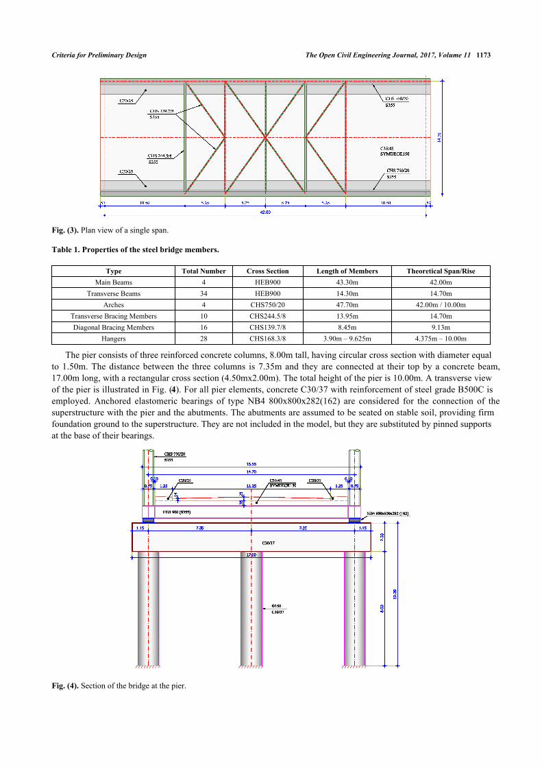
Fig. (3). Plan view of a single span.
Table 1. Properties of the steel bridge members.
Type Total Number Cross Section Length of Members Theoretical Span/RiseMain Beams 4 HEB900 43.30m 42.00m
Transverse Beams 34 HEB900 14.30m 14.70mArches 4 CHS750/20 47.70m 42.00m / 10.00m
Transverse Bracing Members 10 CHS244.5/8 13.95m 14.70mDiagonal Bracing Members 16 CHS139.7/8 8.45m 9.13m
Hangers 28 CHS168.3/8 3.90m – 9.625m 4.375m – 10.00m
The pier consists of three reinforced concrete columns, 8.00m tall, having circular cross section with diameter equalto 1.50m. The distance between the three columns is 7.35m and they are connected at their top by a concrete beam,17.00m long, with a rectangular cross section (4.50mx2.00m). The total height of the pier is 10.00m. A transverse viewof the pier is illustrated in Fig. (4). For all pier elements, concrete C30/37 with reinforcement of steel grade B500C isemployed. Anchored elastomeric bearings of type ΝΒ4 800x800x282(162) are considered for the connection of thesuperstructure with the pier and the abutments. The abutments are assumed to be seated on stable soil, providing firmfoundation ground to the superstructure. They are not included in the model, but they are substituted by pinned supportsat the base of their bearings.
Fig. (4). Section of the bridge at the pier.

1174 The Open Civil Engineering Journal, 2017, Volume 11 Vassilopoulou et al.
3.2. Deformation Limits
Limiting values of various types of displacements are generally not directly associated with certain limit states ofthe structure. Thus, only simplified approaches are possible. Most researchers [30 - 32] support the view thatsettlements less than 5cm are tolerable or acceptable; which could constitute a performance criterion for theServiceability Limit State (SLS). The same value is also suggested by EN1997-1 in Annex H [33]. Furthermore,settlements larger than 6cm could cause severe structural damage, while settlements up to 10cm are harmful, thusintolerable. This could correspond to an Ultimate Limit State (ULS) condition.
Assuming that the settlement of the abutment is practically zero, limiting values of differential settlements willcorrespond to the allowable vertical displacement of the pier. AASHTO [34, 35] sets a limit of 0.008rad in theallowable angular distortion of simply supported bridges. Taking into account that the span between the pier and theabutment of the bridge under study is 42m, the aforementioned value corresponds to a differential settlement of 33.6cmbetween the pier and the abutments. It should be mentioned that the angular distortion is defined as the ratio of thedifferential settlement between two consecutive foundations over the span length. Moulton et al. [36], instead, set alimit in the allowable angular distortion equal to 0.005rad, which, in case of this bridge, corresponds to 21cm. Finally,according to EN1997-1 [33], a limiting value of 0.002rad is set in the allowable angular distortion of such structures forServiceability Limit State corresponding to 8.4cm of differential settlement, while, for Ultimate Limit State, a limitingvalue of span/150 is proposed. Applying the Eurocodes in this study, maximum allowable settlements for theServiceability Limit State should not exceed 8.5cm, while for the Ultimate Limit State the limit arises at 28cm.
In ULS, according to several researchers [30, 31] and [36], horizontal displacements up to 2.5cm are consideredtolerable, values between 2.5cm and 5cm are harmful, while displacements larger than 5cm could cause structuraldamage, thus are defined as intolerable. Moulton et al [36] suggested that the value of horizontal displacement of thepier footing equal to 38mm could constitute a performance criterion for the SLS condition. In case the horizontaldisplacement coexists with settlement, the tolerable value is 25mm.
Regarding the studied bridge the most critical structural member is the pier, which essentially dictates the toleranceof the entire system to liquefaction-induced deformations. In this system, where the pier is a simple cantilever in thelongitudinal direction of the bridge, when longitudinal displacements or rotations in the transverse direction of thebridge prevail, the formation of plastic hinges at its base is not allowed, since the structural system becomes amechanism, unable to carry even the vertical loads (Fig. 5). Moreover, when rotations about the longitudinal axis aredominant, the pier of the bridge under investigation acts as a statically indeterminate frame, thus, the formation ofplastic hinges is allowed at the top of its columns (Fig. 6). Hence, the maximum permissible ground settlement androtations correspond to the first yield at the pier base, or the formation of plastic hinge at the top of the pier, or theplastic resistance of the steel members, whichever occurs first.
Fig. (5). A statically determinate bridge becomes a mechanism after the formation of a plastic hinge at the base of the pier.

Criteria for Preliminary Design The Open Civil Engineering Journal, 2017, Volume 11 1175
Fig. (6). For rotation about the longitudinal axis of the bridge, the pier acts as a frame and plastic hinges are allowed at the top of itscolumns.
3.3. Nonlinear Analyses
3.3.1. Numerical Model
In order to simulate the behaviour of the arched steel road bridge imposed to differential displacements androtations, a numerical model using the finite element analysis software ADINA [25] is developed. Geometric andmaterial nonlinearities are taken into account. For the configuration of the numerical model, three different types offinite elements are employed. Beam elements are used for the modelling of the main beams, the secondary beams, thearches, the transverse bracing members and the structural elements of the pier (columns and concrete beam). Trusselements simulate the diagonal bracing members and the hangers. Regarding the concrete slab, shell elements with athickness of 25cm, accounting for the mean value of the total thickness, are selected. The numerical model of the bridgeis illustrated in Fig. (7).
Fig. (7). Numerical model of the bridge.
The connection of the slab through bearings with the abutments and the pier are simulated by horizontal and verticalequivalent nonlinear springs. As the abutments are not modelled in the present study, the corresponding springs areconsidered fixed at their base. The initial stiffness of each spring imposed to horizontal and vertical displacements iscalculated according to EN1337 [37, 38] and EN1998 [39].
3.3.2. Material Laws
Nonlinear analyses are conducted taking into account the geometric and material nonlinearity through theirconstitutive laws. The material law of structural steel S355 is depicted in Fig. (8a) according to the codes [40 - 42]. Thenonlinear behaviour of the columns of the pier is modelled by means of Μoment-curvature (M-φ) diagrams, shown inFig. (8b), that have been calculated for characteristic values of axial forces using the software myBiaxial [43 - 44],assuming that the longitudinal reinforcement of the columns is 45Φ25 placed at equal distances with a cover of 8cm.

1176 The Open Civil Engineering Journal, 2017, Volume 11 Vassilopoulou et al.
The maximum and minimum value of the axial force taken into consideration for the Moment – Curvature diagramsequals the strength of the cross section of the pier columns to uniaxial tension and compression, respectively, the valuesof which are derived by the interaction diagram M-N of the section, calculated by software Response-2000 [45]. Thenonlinear behaviour of the horizontal springs, simulating the bearings of the abutments and the pier, is described by theForce-Displacement (F-δ) curve denoting the maximum tolerable displacement of the bearing according to the pertinentcodes (Fig. 8c). More specifically, according to EN1998 [39], the shear strain γq,d of the elastomer due to translationalmovement, defined as the ratio of the maximum resultant horizontal relative displacement of parts of the bearing overthe total thickness of the elastomer (γ=δ/t), shall not exceed the value of 2.00, corresponding to a horizontal deformationbetween the upper and lower surfaces of the bearings equal to δq,d=0.324m. Moreover, the maximum design strain γt,d,defined as the sum of the shear strain due to translational movement γq,d, the design strain due to compressive loads γc,d
and the nominal strain due to angular rotation γα,d, shall not exceed the maximum value of 7.00 leading to a maximumhorizontal deformation of maxδt,d=1.13m. The horizontal springs that simulate the stiffness of the bearings to horizontaldisplacements are assumed to have nonlinear behaviour acting linearly up to a horizontal movement of δq,d, while theylose their stiffness if this limit is exceeded but the analysis continues until their horizontal deformation reaches the valueof maxδt,d. The stiffness of the horizontal springs is calculated equal to k=3556kN/m, thus the force F of the diagrams isgiven as F = k · δ. A very large stiffness is assumed for the vertical springs.
Fig. (8). (a) Material law of structural steel, (b) Moment – Curvature diagrams for the pier columns, (c) Material law of the springsmodelling the bearings.
3.3.3. Imposed Loads
Three load cases are taken into account: the self-weight (LC1), the superimposed loads including the weight of thepavement and the sidewalks (LC2) and the imposed displacements or rotations at the base of the pier (LC3). Morespecifically, LC3 describes displacements (dx, dy, ρ) and rotations (θx, θy) applied at the base of each pier column,simulating the liquefaction induced ground movements in case of a seismic event. Each displacement and rotation isimposed separately without taking into account combinations between them. All partial factors are considered equal toone. No live loads are considered, as they act favourably, causing additional compression to the pier, which is the mostvulnerable component of the bridge to ground movements.
Special attention is drawn on the modelling of the support at the footing of the pier columns, accounting for a fixedconnection. Namely, when LC1 and LC2 are exerted it is considered that the pier columns remain fixed at their base.Nevertheless, as the applied displacements and rotations evolve, the corresponding degrees of freedom are released. Tothis end, springs with infinite stiffness in the direction of the imposed displacements and rotations are employed that areactivated for the first two load cases and deactivated for the last one allowing the movement at the base of the pier toevolve.
3.3.4. Sequence of Imposed Loads
The application of the loads is realized in several time steps, as is common in nonlinear analysis, in order to
-1200
-600
0
600
1200
-1.2 -0.6 0.0 0.6 1.2F [k
N]
δ [m]
(a) (c) (b)

Criteria for Preliminary Design The Open Civil Engineering Journal, 2017, Volume 11 1177
simulate the real behaviour of the bridge in an accurate way. In particular, from t=0 to t=0.995 the self-weight of thesteel structure is applied without taking into account the stiffness of the composite deck. At t=1, the shell elements ofthe concrete slab are activated while the superimposed loads begin to evolve. The imposition of LC2 (superimposedloads) is completed at t=2 when the springs with the infinite stiffness at the base of the pier are deactivated. From t=2 tot=3, the liquefaction induced movements are applied, taking into consideration the geometric and material nonlinearitiesof the system. The loading sequence is presented in Table 2.
Table 2. Loading sequence.
Time Period (t) LC1 LC2 LC3 Surface Elements Pier Support0 0% 0% 0% ̶ √
0.995 100% 0% 0% ̶ √1 100% 0% 0% √ √2 100% 100% 0% √ ̶3 100% 100% 100% √ ̶
3.3.5. Method of Analysis
Nonlinear static analyses are performed and the response of the pier columns, the steel elements and the elastomericbearings due to imposed ground movements is monitored until the first failure occurs. Then, the maximum tolerabledisplacements and rotations at the footing of the pier are detected and the behaviour of the crucial bridge components isassessed comparing their response with the corresponding material laws. The response of the structural members, whichare deemed easily repairable or replaceable, such as the continuous slab and the expansion joints, is not considered to becrucial for the definition of the tolerable movements at the foundation of the pier, as they cannot cause a total failure ofthe bridge. Although the bearings are considered replaceable, their stiffness is reduced in case they fail and the responseof the whole bridge is affected. This eventual change of their stiffness is taken into account in the analysis, through theirmaterial law.
4. RESULTS
4.1. Tolerable Displacements and Rotations of the Pier
The sensitivity of the bridge to imposed displacements and rotations with respect to the global axes is investigatedin this section and the permissible limits are defined.
4.2. Response of the Bridge to Induced Ground Displacement dx
The vertical loads in combination with the ground displacement about the longitudinal axis x, as well as thecorresponding deformed structure, are presented in Fig. (9). The maximum displacement dx reaches the value of 0.52mat t=2.99 and flexural failure occurs at the base of the outer pier columns. Nevertheless, the first yield of the piercolumns occurs at t=2.75 when the horizontal displacement becomes 0.40m. As already explained, for longitudinalmovements the pier is considered as cantilever and no plastic hinges are allowed at its base, thus the maximumpermissible displacement for the bridge is considered equal to 0.40m that causes the first yield to the middle column ofthe pier.
Fig. (9). (a) Vertical loads and imposed ground displacement dx, (b) Deformed state due to imposed ground displacement dx.
(a) (b)

1178 The Open Civil Engineering Journal, 2017, Volume 11 Vassilopoulou et al.
At the last time step of the nonlinear analysis, the magnitude of the developed axial force at the footing of thecolumns is calculated, the M-φ diagrams are plotted for all columns of the pier, and the response of all critical bridgecomponents is compared with the corresponding material laws. The behaviour of the bridge to horizontal grounddisplacement is represented by the three representative diagrams of Fig. (10), describing the response of the mostcritical column of the pier at the point of the first hinge creation, the bearings and the main beams, which develop themaximum stress among the steel members of the superstructure. In Fig. (10a) the bending moment My of the piercolumn is plotted, referring to the local axis y, which is parallel to the global Y-axis. The pier columns prove to be themost vulnerable elements for this ground movement, exhausting their capacity first among all other components of thebridge, whereas the springs simulating the elastomeric bearings and all the steel members remain elastic.
Fig. (10). Response of the bridge components to ground displacement dx (a) Moment – Curvature (M-φ) diagram for the base of theouter pier columns, (b) Maximum Force – Displacement (F-δ) diagram for the bearings, (c) Maximum stress – strain (σ-ε) diagramfor the main beams.
The developed internal forces and deformations of the characteristic bridge members are illustrated in Fig. (11) asfunctions of the time of the imposed loads. It can be observed that the pier columns develop significant internal bendingmoments through the imposition of the longitudinal displacement dx (from t=2 to t=3), while the vertical loads do notinduce bending (from t=0 to t=2). Regarding the springs simulating the bearings, significant shear deformations aredeveloped, when the displacement dx is exerted at the footing of the pier (from t=2 to t=3), without though leading totheir failure. The main beams are influenced by the imposition of the longitudinal displacement developing stress equalto 220MPa that does not exceed the yield stress.
Fig. (11). Evolution of the bridge response to ground displacement dx (a) Moment – time (M-t) diagram for the pier columns, (b)Shear deformation – time (γ-t) diagram for the bearings, (c) Stress – time (σ-t) diagram for the main beams.
A Damage Index (DI) is used for each component of the bridge, defined as DI=Ed/Rd. Ed is the calculated response
(a) (b) (c)
(a) (b) (c)

Criteria for Preliminary Design The Open Civil Engineering Journal, 2017, Volume 11 1179
of the bridge by means of the maximum bending moment of the pier columns, the maximum stress for the steelmembers and the maximum strain for the bearings the moment of the first yield for the columns of the pier. Rd is themagnitude that defines the strength of each component, namely the yielding bending moment of the pier columns withrespect to the developed axial force derived from the M-φ diagrams, the ultimate stress fu=510MPa for the steelmembers and the limit of the maximum shear strain γq,d=2 for the bearings, as the translational movement prevails. Theevolution of damage is illustrated in Fig. (12) by means of the DI for the whole analysis up to first failure, where it isshown that DI for the pier columns increases continuously, while the bearings exhaust only half of their capacity atfailure. All other components of the bridge are slightly affected by the ground horizontal displacement dx. At first yield,the horizontal displacement takes the value of 0.40m and the DI of the pier columns becomes equal to 1, defining thedesign limit for the induced ground horizontal longitudinal displacement. The maximum value of DI is 1.25, accountingfor the formation of the first plastic hinge at the outer columns of the pier. The results corresponding to the design limitof the displacement dx=0.40m are summarized in Table 3, giving the maximum response of each component of thebridge, with respect to the strength and their DI.
Fig. (12). Damage indices for ground displacement dx.
Table 3. Response of the bridge members to ground displacement dx=0.40m and damage indices (DI).
Structural Members Response (Ed) Strength (Rd) DI (Ed/Rd)Pier Columns 5255kNm Bending Moment 5207kNm 1.00Main Beams 175MPa
Ultimate Stress 510MPa
0.34Transverse Beams 88MPa 0.17
Arches 155MPa 0.30Transverse Bracing Members 37MPa 0.07Diagonal Bracing Members 12MPa 0.02
Hangers 173MPa 0.34Bearings 1.02 γq,d = 2 0.51
4.3. Response of the Bridge to Induced Ground Displacement dy
In this case, the sum of the vertical loads and the displacement in the transverse direction of the bridge areconsidered (Fig. 13a). The deformed geometry of the structure is presented in Fig. (13b), where it can be observed thatthe bearings of the pier develop significant translational deformations, being thus the most vulnerable components ofthe bridge. The nonlinear analysis stops at t=2.89, when the displacement dy is equal to 2.32m, as the bearings of thepier are not capable to sustain the increased transverse displacement. However, the maximum shear strain of the

1180 The Open Civil Engineering Journal, 2017, Volume 11 Vassilopoulou et al.
bearings is reached at t=2.28 for a ground displacement dy equal to 0.72m, which constitutes the design limit for thisground movement. After this value the system deforms without resistance, as the connection of the deck with the pier islost due the annihilation of the bearings stiffness.
Fig. (13). (a) Vertical loads and imposed ground displacement dy, (b) deformed state due to imposed ground displacement dy.
The comparison between the response of the critical components of the bridge and their corresponding material lawsis illustrated in Fig. (14). It is noted that first the springs, modelling the bearings of the pier, reach failure due totranslational movement, whereas the pier columns exceed their elastic limit, without though corresponding to failure, asthe pier in the transverse direction forms a frame and the creation of the plastic hinges is permitted. The bendingmoment Mz of Fig. (14b) refers to the local axis z of the pier columns, which is parallel to the global X-axis. Among thesteel members, the maximum stress is calculated at the hangers, which is equal to 167MPa, remaining though in theelastic zone. The diagrams describing the developed internal forces with respect to time are plotted in Fig. (15). It isnoted that the members of the bridge such as the pier columns and the hangers develop stress until t1=2.28, when thestiffness of the springs becomes zero, while after that time the pier moves independently without resisting the imposedtransverse displacement.
Fig. (14). Response of the bridge components to ground displacement dy (a) Maximum Force – Displacement (F-δ) diagram for thebearings of the pier, (b) Moment – Curvature (M-φ) diagram for the outer pier column, (c) Maximum stress – strain (σ-ε) diagram forthe hangers.
(a) (b) (c)

Criteria for Preliminary Design The Open Civil Engineering Journal, 2017, Volume 11 1181
Fig. (15). Evolution of the bridge response to ground displacement dy (a) Shear deformation – time (γ-t) diagram for the bearings ofthe pier, (b) Moment – time (M-t) diagram for the pier columns, (c) Stress – time (σ-t) diagram for the hangers.
Summarizing the results for all bridge components, the DI is calculated and the evolution of the damages is shownin Fig. (16) by means of the DI for the whole analysis. It is noted that the bearings first lose their stiffness as the shearstrain exceeds its limit and then they reach total failure. The DI for the pier columns increases until the stiffness of thebearings becomes zero, reaching a value of DI=0.91. All other bridge components are not influenced significantly bythe horizontal ground displacement dy, remaining in the elastic zone. When the stiffness of the bearings becomes zero,the horizontal displacement takes the value of 0.72m and the DI of the bearings becomes equal to 1, setting the designlimit for the induced horizontal transverse ground displacement. The maximum value of the DI is 3.50, accounting forthe failure of the bearings. The results corresponding to the design limit of the displacement dy are given in Table 4, bymeans of the maximum response of each component of the bridge with respect to the strength and their DI.
Fig. (16). Damage indices for ground displacement dy.
(a) (b) (c)

1182 The Open Civil Engineering Journal, 2017, Volume 11 Vassilopoulou et al.
Table 4. Response of the bridge components to ground displacement dy=0.72m and damage indices (DI).
Structural Members Response (Ed) Strength (Rd) DI (Ed/Rd)Pier Columns 6008.80kNm Bending Moment 6584.32kNm 0.91Main Beams 104MPa
Ultimate Stress 510MPa
0.20Transverse Beams 73MPa 0.14
Arches 125MPa 0.25Transverse Bracing Members 38MPa 0.07Diagonal Bracing Members 13MPa 0.03
Hangers 167MPa 0.33Bearings 2 γq,d = 2 1.00
4.4. Response of the Bridge to Induced Settlement ρ
Next, the behaviour of the bridge to imposed settlement due to soil liquefaction is studied. After the imposition ofthe superimposed loads (t=2), vertical forces equal to the corresponding reactions are exerted at the base of the piercolumns. The magnitude of the aforementioned forces is decreased gradually, allowing the settlement of the bridge. Theanalysis stops at t=3.00, when the settlement of the pier reaches the value of 2.58m, due to large rotational deformationof the bearings. The applied loads and the deformed geometry of the bridge are depicted in Fig. (17), showing largeinclination of the deck due to the pier settlement. In such case severe damage occurs at the continuous slab connectingthe two spans. However, as it is considered replaceable, its large deformations do not indicate an overall bridge failure.Nevertheless, for such large settlements the shear deformation of the bearings is significant, reaching to failure. Themaximum tolerable settlement is 2.58m that is considered quite high and cannot constitute a design criterion. At thattime, it is certain that the bridge would have lost its serviceability due to the failure of the continuous concrete slab andthe large inclination of the deck. According to EN1997-1 [33], as already mentioned, the maximum allowablesettlement is equal to 28cm.
Fig. (17). (a) Vertical loads and imposed settlement ρ (b) Deformed state due to imposed settlement ρ.
Such settlement causes significant rotation of the bearings about the transverse axis of the bridge, while theirtranslational movement is negligible. The diagram of the angular rotation φy of the abutments’ bearings presenting themaximum total strain γ is plotted in Fig. (18a), showing that at the end of the analysis the total strain reaches the valueof the maximum design strain equal to 7, as defined in section 5.2. The columns of the pier do not develop significantadditional internal forces due to the settlement, as they move vertically without resisting, being thus the less vulnerablecomponents of the bridge for this kind of ground movement. The main beams are the most critical steel members of thesuperstructure developing the largest stress, due to increased tension forces and bending moments at their ends. Themaximum stress of the main beams at the end of the analysis is equal to 356MPa, slightly exceeding the yield stress, asplotted in Fig. (18b) along with the material law. The DI is calculated for all components of the bridge and the evolutionof the damages is plotted in Fig. (19) by means of these indices, while the results of the analysis are listed in Table 5. Itis noted that the bearings first lose their stiffness as the angular rotation increases rapidly and the total strain reaches thedesign limit of 7, defining the failure of the bearings. The main beams show an increasing DI until they reach the yield
(a) (b)

Criteria for Preliminary Design The Open Civil Engineering Journal, 2017, Volume 11 1183
stress taking the value of 0.70, but entering in the plastic zone their DI remains almost unaltered. All other steelmembers of the bridge are represented by DI smaller than 0.50, corresponding to low damage levels. The DI for thecolumns of the pier is defined by the ratio of their axial force over the maximum pure compressive force they cansustain, as the bending moments are negligible.
Fig. (18). Response of the bridge components to settlement ρ (a) Moment – Curvature (M-φ) diagram for the bearings of theabutments, (b) Maximum stress – strain (σ-ε) diagram for the main beams.
Fig. (19). Damage indices for settlement ρ.
Table 5. Response of the bridge components to settlement ρ=2.58m and damage indices (DI).
Structural Members Response (Ed) Strength (Rd) DI (Ed/Rd)Pier Columns 4534.86kN Compressive Force 39000kN 0.12Main Beams 356MPa
Ultimate Stress 510MPa
0.70Transverse Beams 200MPa 0.39
Arches 239MPa 0.47Transverse Bracing Members 43MPa 0.09Diagonal Bracing Members 13MPa 0.02
Hangers 210MPa 0.41Bearings 7 γt,d = 7 1.00
(a) (b)

1184 The Open Civil Engineering Journal, 2017, Volume 11 Vassilopoulou et al.
4.5. Response of the Bridge to Induced Ground Rotation θx
Rotation along the longitudinal axis x is applied at the base of the pier columns, in combination with the sum of thesuperimposed loads, as illustrated in Fig. (20a). The application of rotation θx is realized by imposing vertical forces atthe base of the outer pier columns that are equivalent to the developed reaction forces at t=2. From t=2 to t=3, themagnitude of one vertical force is increased whereas the value of the other is decreased, allowing the rotation of thebridge about the longitudinal axis x. The nonlinear analysis stops at t=2.99, when θx=0.025rad, due to bending failure atthe top of the outer pier columns. The deformed state at the moment of failure is depicted in Fig. (20b).
Fig. (20). (a) Vertical loads and imposed ground rotation θx, (b) Deformed state due to imposed ground rotation θx.
Due to the imposed rotation θx the pier acts as a frame, hence significant bending moments develop at the top of itscolumns, leading to the creation of plastic hinges defining flexural failure. The M-φ diagrams are plotted in Fig. (21a),where it is noted that the columns exhaust their capacity. Regarding the bearings, the load-displacement diagram of thehorizontal springs in the transverse direction is illustrated in Fig. (21b), where it is noted that they behave elasticallyuntil the end of the analysis. The maximum stress-strain diagram for the arches is given in Fig. (21c) in comparisonwith the material law. The arches present the maximum stress among the steel members of the bridge, equal to 229MPathat corresponds to 90% of the yield stress. Monitoring the response of all components of the bridge the evolution of theDI is calculated and shown in Fig. (22) for the whole time of analysis. It is noted that this index increases continuouslyfor the pier columns until it reaches the value of 1 accounting for failure, while the DI for the bearings and the steelmembers remain below 0.50, indicating elastic behaviour. The results corresponding to the design limit of rotation θx
are given in Table 6 by means of the maximum response of each component of the bridge with respect to the strengthand their DI.
Fig. (21). Response of the bridge components to ground rotation θx (a) Moment – Curvature (M-φ) diagram at the top of the outerpier columns (b) Maximum Force – Displacement (F-δ) diagram for the bearings of the pier, (c) Maximum stress – strain (σ-ε)diagram for the arches.
(a) (b)
(a) (b) (c)
Criteria for Preliminary Design The Open Civil Engineering Journal, 2017, Volume 11 1185
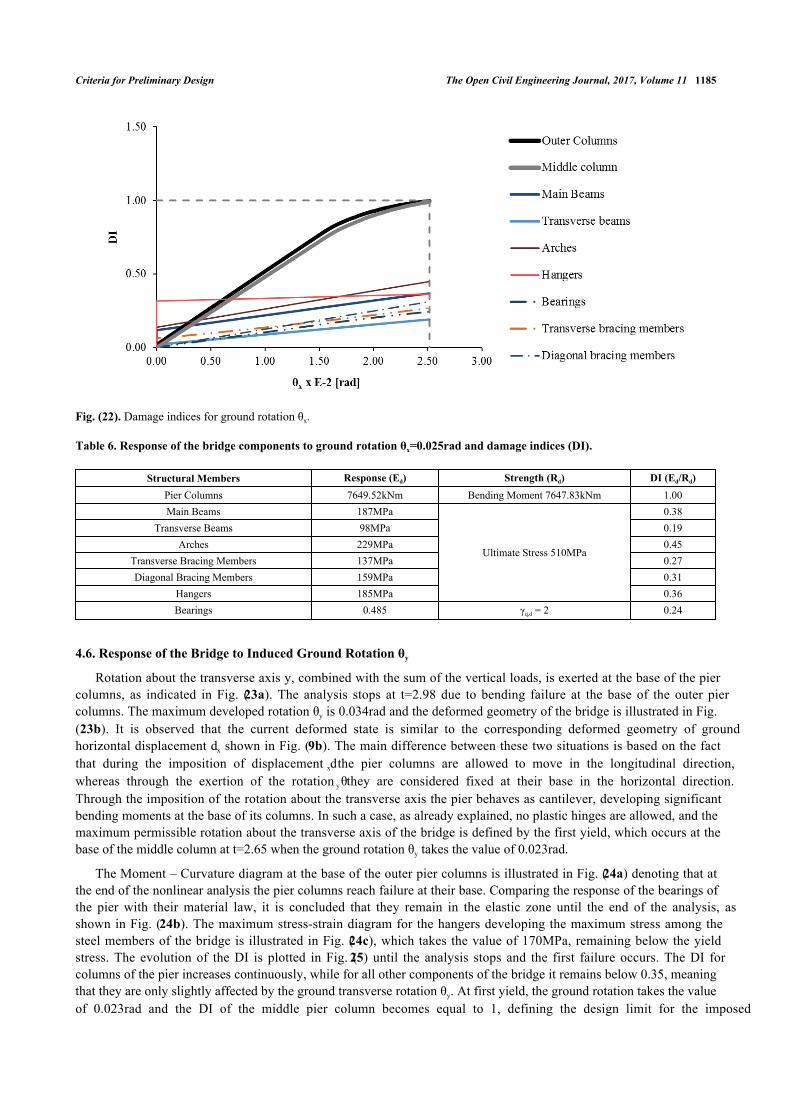
Fig. (22). Damage indices for ground rotation θx.
Table 6. Response of the bridge components to ground rotation θx=0.025rad and damage indices (DI).
Structural Members Response (Ed) Strength (Rd) DI (Ed/Rd)Pier Columns 7649.52kNm Bending Moment 7647.83kNm 1.00Main Beams 187MPa
Ultimate Stress 510MPa
0.38Transverse Beams 98MPa 0.19
Arches 229MPa 0.45Transverse Bracing Members 137MPa 0.27Diagonal Bracing Members 159MPa 0.31
Hangers 185MPa 0.36Bearings 0.485 γq,d = 2 0.24
4.6. Response of the Bridge to Induced Ground Rotation θy
Rotation about the transverse axis y, combined with the sum of the vertical loads, is exerted at the base of the piercolumns, as indicated in Fig. (23a). The analysis stops at t=2.98 due to bending failure at the base of the outer piercolumns. The maximum developed rotation θy is 0.034rad and the deformed geometry of the bridge is illustrated in Fig.(23b). It is observed that the current deformed state is similar to the corresponding deformed geometry of groundhorizontal displacement dx shown in Fig. (9b). The main difference between these two situations is based on the factthat during the imposition of displacement dx the pier columns are allowed to move in the longitudinal direction,whereas through the exertion of the rotation θy they are considered fixed at their base in the horizontal direction.Through the imposition of the rotation about the transverse axis the pier behaves as cantilever, developing significantbending moments at the base of its columns. In such a case, as already explained, no plastic hinges are allowed, and themaximum permissible rotation about the transverse axis of the bridge is defined by the first yield, which occurs at thebase of the middle column at t=2.65 when the ground rotation θy takes the value of 0.023rad.
The Moment – Curvature diagram at the base of the outer pier columns is illustrated in Fig. (24a) denoting that atthe end of the nonlinear analysis the pier columns reach failure at their base. Comparing the response of the bearings ofthe pier with their material law, it is concluded that they remain in the elastic zone until the end of the analysis, asshown in Fig. (24b). The maximum stress-strain diagram for the hangers developing the maximum stress among thesteel members of the bridge is illustrated in Fig. (24c), which takes the value of 170MPa, remaining below the yieldstress. The evolution of the DI is plotted in Fig. (25) until the analysis stops and the first failure occurs. The DI forcolumns of the pier increases continuously, while for all other components of the bridge it remains below 0.35, meaningthat they are only slightly affected by the ground transverse rotation θy. At first yield, the ground rotation takes the valueof 0.023rad and the DI of the middle pier column becomes equal to 1, defining the design limit for the imposed

1186 The Open Civil Engineering Journal, 2017, Volume 11 Vassilopoulou et al.
transverse ground rotation. The maximum value of the DI is 1.29, accounting for the time of the first plastic hingecreation at the outer columns of the pier. The results corresponding to the design limit of rotation θy are listed in Table7, by means of the maximum response of each component of the bridge, with respect to the strength and their DI.
Fig. (23). (a) Vertical loads and imposed ground rotation θy, (b) Deformed state due to imposed ground rotation θy.
Fig. (24). Response of the bridge components to ground rotation θy (a) Moment – Curvature (M-φ) diagram at the base of the outerpier columns, (b) Maximum Force – Displacement (F-δ) diagram for the bearings of the pier, (c) Maximum stress – strain (σ-ε)diagram for the hangers.
Fig. (25). Damage indices for ground rotation θy.
(a) (b)
(a) (b) (c)

Criteria for Preliminary Design The Open Civil Engineering Journal, 2017, Volume 11 1187
Table 7. Response of the bridge components to ground rotation θy=0.023rad and damage indices (DI).
Structural Members Response (Ed) Strength (Rd) DI (Ed/Rd)Pier Columns 5075.91kNm Bending Moment 5068.24kNm 1.00Main Beams 140MPa
Ultimate Stress 510MPa
0.28Transverse Beams 86MPa 0.17
Arches 139MPa 0.27Transverse Bracing Members 36MPa 0.07Diagonal Bracing Members 11MPa 0.02
Hangers 168MPa 0.33Bearings 0.39 γq,d = 2 0.19
5. DISCUSSION
5.1. Final Results
All results from the analyses conducted for the arched steel bridge are summarized in Table 8. The groundmovements that are found to be most critical are the ones that cause large bending moments at the base of the piercolumns, namely horizontal displacement dx and rotation θy. In this case study, the design criterion defining themaximum tolerable ground movement dictates that no plastic hinges should be created at the base of the pier, as it isconsidered to be a cantilever system, leaving though some margins until the formation of the hinges which will lead tototal collapse.
Table 8. Maximum and allowable limits of ground induced movements.
Ground Induced Movement Structural Member Maximum Value Allowable Limit [33]Displacement dx Pier Columns (Base) 0.40m -Displacement dy Bearings 0.72m -
Settlement ρ Bearings 2.58m 0.28cmRotation θx Pier Columns (Top) 0.025rad -Rotation θy Pier Columns (Base) 0.023rad -
For this bridge system, consisting of two simply supported spans, the settlement is not as critical as the horizontaldisplacements and rotations, causing only damage at the connection slab of the deck and large rotations at the bearings,which are both repairable and replaceable. The permissible limit for settlement is set by the Eurocodes, which, asmentioned in section 4, is equal to 28cm. It is certain that such limit does not cause any damage in the structuralcomponents of the bridge, as shown in section 6.3 and more specifically in Fig. (19). Nevertheless, combining this valuewith a ground rotation or a horizontal displacement, as usually occurs in a liquefaction phenomenon, the limits of Table8, regarding these predominant ground movements, will be reduced. A combination of the ground movements in alldirections should be taken into consideration in the final design of the bridge [46 - 48]. For example, in [48] a relationbetween the rotation and the settlement is proposed, expressed as θ=0.05ρ, where the rotation θ at the pier footing is indegrees, while the uniform settlement ρ in cm. This means that the permissible rotation θy, which is the smallest valueamong the rotations, equal to 0.023rad (=1.32o), should be combined with a settlement equal to 26cm. This value ismuch smaller than the maximum tolerable settlement of 2.58m calculated in section 6.3. The bridge remains almostintact to such a vertical displacement, thus, a ground movement combination does not alter significantly the permissiblerotations of Table 8.
It should be mentioned that buckling of steel members was taken into account for their dimensioning and finalselection of their cross sections at ULS. In all cases of ground movement studied in this work, the arches, which are themain compressive steel members of the superstructure, develop axial forces almost half of the ones calculated at ULSand almost one third of their design buckling resistance. All other members develop stresses much smaller than thearches, thus they are not considered to be susceptible to buckling. Hence, as loss of buckling resistance is not expectedfor the members of the superstructure due to liquefaction movements, for simplicity buckling of steel members isneglected at this preliminary design stage.
The allowable limits of ground movements, derived by the procedure presented herein, are used for the preliminary

1188 The Open Civil Engineering Journal, 2017, Volume 11 Vassilopoulou et al.
design of the pier spread footing and the dimensions of the “crust”. The final design of the bridge should include theentire model of the bridge with the pier foundation and appropriate springs and dashpots simulating the soil-foundation-structure interaction effects for the static and dynamic response of the bridge, taking also into account the particularstratification of the subsoil. The permanent loads, live loads, seismic action and a combination of initial imperfectionsto ensure the stability of the steel members against buckling should be considered in this final design stage.
CONCLUSION
The bridge under investigation is a steel arch road bridge with two simply supported spans, with a middle pierconsisting of three circular reinforced concrete columns connected at their top with a concrete beam, forming thus aframe in the transverse direction of the bridge, and at their base with a common spread footing. In this study the footingis not simulated. Instead, fixed supports are considered at the base of the columns. The bridge is supposed to be seatedon a layer of non-liquefiable “crust” lying over a liquefaction susceptible soil. Additional permanent groundmovements, by means of horizontal displacements, settlement and rotations may occur after a major earthquake event.The behaviour of the bridge is investigated in order to determine the permissible ground movements without loss of itsserviceability and resistance setting the allowable limits of the preliminary design of the pier footing and dimensioningof the “crust”.
The design criteria set in this study specify that for the assumed pier system plastic hinges at the base of the columnsare not allowed, because they would lead to the collapse of the bridge. The analyses showed that the pier and bearingsare the most vulnerable components of the bridge. Failure occurs at the bearings only in case of ground transversedisplacement and settlement, while all other ground movements cause failure at the pier columns. As expected for asimply supported bridge, the settlement itself does not constitute a critical limit, but in combination with rotationsor/and horizontal movements could define a design criterion for the foundation of the bridge.
CONSENT FOR PUBLICATION
Not applicable.
CONFLICT OF INTEREST
The authors declare no conflict of interest, financial or otherwise.
ACKNOWLEDGEMENTS
The work presented here was carried out in the framework of research program “Innovative design of bridge pierson liquefiable soils with the use of natural seismic isolation”, having Professor George Bouckovalas as principalinvestigator. This research has been co-financed by the European Union (European Social Fund - ESF) and GreekNational funds through the Operational Program “Education and Lifelong Learning” of the National StrategicReference Framework (NSRF) – Research Funding Program: THALES: Reinforcement of the interdisciplinary and/orinter-institutional research and innovation.
REFERENCES
[1] W.D. Meyersohn, "Pile response to liquefaction – induced lateral spread", Ph.D. Dissertation, Cornel University, Ithaca, NY, USA, 1994.
[2] A.S. Mokhtar, M.A. Abdel-Motaal, and M.M. Wahidy, "Lateral displacement and pile instability due to soil liquefaction using numericalmodel", Ain Shams Eng. J., vol. 5, no. 4, pp. 1019-1032, 2014.[http://dx.doi.org/10.1016/j.asej.2014.05.002]
[3] Soil Liquefaction Department of Civil Engineering, University of Washington. Available at: https://depts.washington.edu/liquefy/html/main.html
[4] P. P. Xanthakos, L. W. Abramson, and D. A. Bruce, Ground Control and Improvement, John Wiley and Sons, Inc.: New York, 1994.
[5] S.L. Kramer, "Geotechnical earthquake engineering", In: W.J. Hall, Ed., Prentice-Hall International Series in Civil Engineering andEngineering Mechanics., Prentice-Hall, Inc.: Upper Saddle River, NJ, USA, 1996. [ISBN 0133749436]
[6] D. Karamitros, G. Bouckovalas, and Y. Chaloulos, "Performance-based design of bridge foundation on partially improved liquefiable soil",In: Second International Conference on Performance Based Design in Earthquake Geotechnical Engineering, Taormina, Italy, May 28-30,2012.
[7] T. Adachi, S. Iwai, M. Yasui, and Y. Sato, "Settlement and inclination of reinforced concrete buildings in Dagupan City due to liquefactionduring the 1990 Philippine earthquake", In: Tenth World Conference on Earthquake Engineering (10WCEE), vol. 1. A. A. Balkema:Rotterdam, July 19-24, 1992, pp. 147-152.

Criteria for Preliminary Design The Open Civil Engineering Journal, 2017, Volume 11 1189
[8] E. Cascone, and G. Bouckovalas, "Seismic bearing capacity of footings on saturated sand with clay cap", In: Eleventh European Conferenceon Earthquake Engineering, Paris, France, September 6-11, 1998. and in Proceedings of Eleventh European Conference on EarthquakeEngineering, P. Bisch, P. Labbe, A. Pecker, Eds. Rotterdam: A. A. Balkema, 1998. [ISBN 9054109823]
[9] A. Elgamal, J. Lu, and Z. Yang, "Liquefaction-induced settlement of shallow foundations and remediation: 3D numerical simulation", J.Earthquake Eng., vol. 9, no. sup001, pp. 17-45, 2005.[http://dx.doi.org/10.1080/13632460509350578]
[10] J.F. Bird, J.J. Bommer, H. Crowley, and R. Pinho, "Modelling liquefaction-induced building damage in earthquake loss estimation", Soil.Dyn. Earthquake Eng., vol. 26, no. 1, pp. 15-30, 2006.[http://dx.doi.org/10.1016/j.soildyn.2005.10.002]
[11] G.D. Bouckovalas, and P. Dakoulas, "Liquefaction performance of shallow foundations in presence of a soil crust", In: Fourth InternationalConference on Earthquake Geotechnical Engineering (4ICEGE). Thessaloniki, Greece, June 25-28, 2007, and in Earthquake GeotechnicalEngineering: Fourth International Conference on Earthquake Geotechnical Engineering - Invited Lectures, K. D. Pitilakis Ed. London:Springer, 2007.[http://dx.doi.org/10.1007/978-1-4020-5893-6_11]
[12] D.K. Karamitros, G.D. Bouckovalas, and Y.K. Chaloulos, "Seismic settlements of shallow foundations on liquefiable soil with a clay crust",Soil. Dyn. Earthquake Eng., vol. 46, pp. 61-76, 2013.[http://dx.doi.org/10.1016/j.soildyn.2012.11.012]
[13] D. K. Karamitros, G. D. Bouckovalas, and Y. K. Chaloulos, "Insight to the seismic liquefaction performance of shallow foundations", J.Geotech. Geoenviron., vol. 139, no. 4, 2013.[http://dx.doi.org/10.1061/(ASCE)GT.1943-5606.0000797]
[14] G. Bouckovalas, "THALIS-NTUA: Innovative design of bridge piers on liquefiable soils with the use of natural seismic isolation – WP3:Analytical methodology for the design of shallow foundations on liquefiable soil", Technical Report, School of Civil Engineering, NationalTechnical University of Athens, School of Civil Engineering: Athens, Greece, 2014. Available at:http://users.ntua.gr/gbouck/Thales/Thalis_NTUA(MIS380043)_NAT-SEI-ISO_D3.pdf
[15] K. Tokimatsu, and H.B. Seed, "Evaluation of settlement in sands due to earthquake shaking", J. Geotech. Eng., vol. 113, no. 8, pp. 861-878,1987.[http://dx.doi.org/10.1061/(ASCE)0733-9410(1987)113:8(861)]
[16] K. Ishihara, and M. Yoshimine, "Evaluation of settlements in sand deposits following liquefaction during earthquakes", Soil Found., vol. 32,no. 1, pp. 173-188, 1992.[http://dx.doi.org/10.3208/sandf1972.32.173]
[17] K. Ishihara, A. Acacio, and I. Towhata, "Liquefaction-induced ground damage in Dagupan in the July 16, 1990 Luzon earthquake", SoilFound., vol. 33, no. 1, pp. 133-154, 1993.[http://dx.doi.org/10.3208/sandf1972.33.133]
[18] L. Liu, and R. Dobry, "Seismic response of shallow foundation on liquefiable sand", J. Geotech. Geoenviron., vol. 123, no. 6, 1997.[http://dx.doi.org/10.1061/(ASCE)1090-0241(1997)123:6(557)]
[19] K. Kawasaki, T. Sakai, S. Yasuda, and M. Satoh, "Earthquake induced settlement of an isolated footing for power transmission tower",Proceedings of the International Conference Centrifuge 98, Tokyo, Japan, September 23-25 1998, vol. 1, 1998 Tokyo, Japan T. Kimura, O.Kusakabe and J. Takemura, Eds., Rotterdam: A. A. Balkema, 1998, pp. 271-276. [ISBN 9054109866]
[20] S. Yasuda, T. Terauchi, H. Morimoto, A. Erken, and N. Yoshida, "Post liquefaction behavior of several sands", In: Eleventh EuropeanConference on Earthquake Engineering. September 6-11, 1998 and in Proceedings of Eleventh European Conference on EarthquakeEngineering, P. Bisch, P. Labbe, A. Pecker, Eds. Rotterdam: A. A. Balkema, 1998. [ISBN 9054109823]
[21] A.A. Acacio, Y. Kobayashi, I. Towhata, R.T. Bautista, and K. Ishihara, "Subsidence of building foundations resting upon liquefied subsoil:Case studies and assessment", Soil Found., vol. 41, no. 6, pp. 111-128, 2001.[http://dx.doi.org/10.3208/sandf.41.6_111]
[22] G.D. Bouckovalas, A.I. Valsamis, and K.I. Andrianopoulos, "Pseudo static vs. performance based seismic bearing capacity of footings onliquefiable soil", In: Satellite Conference on Recent Developments in Earthquake Geotechnical Engineering, Osaka, Japan, Sept 10, 2005.
[23] A. Sextos, N. Psilla, I. Psycharis, A. Kappos, O. Taskari, I. Vassilopoulou, E. Mylona, C. Gantes, and G. Bouckovalas, "Performance criteriafor bridges designed with spread footing on liquefiable soils", In: Second European Conference on Earthquake Engineering and Seismology(2ECEES), Istanbul, Turkey, August 25-29, 2014.
[24] A. Psychari, I. Vassilopoulou, and C.J. Gantes, "Sensitivity of a steel arch road bridge to imposed foundation displacements and rotations", In:International Conference – CESARE 14, civil engineering for sustainability and resilience, Amman, Jordan., April 24-27, 2014.
[25] K.J. Bathe, Theory and Modeling Guide. ADINA, Report ARD 08-7., vol. 1. ADINA R & D Inc.: Watertown, MA, USA, 2006.[http://www.adina.com/]
[26] K. Ishihara, "Stability of Natural Deposits during Earthquakes", In: Eleventh International Conference on Soil Mechanics and FoundationEngineering (XI. ICSMFE), August 12-16, 1985, pp. 321-376, San Francisco, USA.
[27] K. Ishihara, "Effects of at-depth liquefaction on embedded foundations during Earthquakes", In: Tenth Asian Regional Conference on SoilMechanics and Foundation Engineering. vol. 2, Beijing, China, August 29 - September 2, 1995.

1190 The Open Civil Engineering Journal, 2017, Volume 11 Vassilopoulou et al.
[28] E. Naesgaard, P.M. Byrne, and G. Ven Huizen, "Behaviour of light structures founded on soil ‘crust’ over liquefied ground", In: SpecialtyConference on Geotechnical Earthquake Engineering and Soil Dynamics III, Seattle, WA, USA Aug 3-6, 1998 and in Geotechnical SpecialPublication, Geotechnical Earthquake Engineering and Soil Dynamics III, vol. 1 no. 75, P. Dakoulas, M. Yegian, and R. D. Holtz, Eds.Reston, VA, USA: American Society of Civil Engineers (Verlag), 1998, pp. 422–433 [ISBN 9780784403617].
[29] G. Bouckovalas, I. Psycharis, C.J. Gantes, A. Sextos, A. Kappos, and F. Mylonakis, "Performance-based design of bridge piers in liquefiablesites with shallow foundation and limited ground improvement", In: Third International Conference on Performance-based Design inEarthquake Geotechnical Engineering (PBD-III). Vancouver, BC, Canada, July 16-19, 2017.
[30] M. Bozozuk, "Bridge foundations move", Transportation Research Record: Tolerable movement of bridge foundations, sand drains, K-test,slopes, and culverts. vol. 678, Series: Transportation Research Board, Washington DC: National Academy of Sciences, pp. 17-21, 1978.[ISBN: 030902823X]
[31] J.L. Walkinshaw, "Survey of bridge movements in the Western United States", Transportation Research Record: Tolerable movement ofbridge foundations, sand drains, K-test, slopes, and culverts, vol. 678, Series: Transportation Research Board: Washington DC: NationalAcademy of Sciences, pp. 6-12, 1978.
[32] A.F. DiMillio, Performance of Highway Bridge Abutments on Spread Footings on Compacted Fill, Report No. FHWA RD-81-184. FederalHighway Administration, U.S. Department of Transportation, 1982.
[33] EN 1997-1:, Geotechnical design – Part 1: General rules., European Committee for Standardization: Brussels, 2004.
[34] AASHTO, Standard Specifications for Highway Bridges, American Association of State Highway and Transportation Officials: Washington,DC, 2002.
[35] AASHTO, AASHTO LRFD Bridge Design Specifications, American Association of State Highway and Transportation Officials: 4th Edition,Washington DC, 2007. with 2009 Interims.
[36] L. K. Moulton, H. V. S. GangaRao, and G. T. Halvorsen, Tolerable Movement Criteria for Highway Bridges., Report No. FHWA RD-85-107,Federal Highway Administration: U.S. Department of Transportation, 1985.
[37] ΕΝ1337-1:, Structural bearings – Part 1: General design rules, European Committee for Standardization: Brussels, 2000.
[38] ΕΝ1337-3:, Structural bearings – Part 3: Elastomeric bearings, European Committee for Standardization: Brussels, 2005.
[39] EN 1998-2:, Design of structures for earthquake resistance - Part 2: Bridges, European Committee for Standardization: Brussels, 2005.
[40] EN1993-1.1:, Design of steel structures – Part 1.1: General rules and rules for buildings, European Committee for Standardization: Brussels,2005.
[41] EN1993-2:, Design of steel structures – Part 2: Steel Bridges., European Committee for Standardization: Brussels, 2006.
[42] EN1994-1.1:, Design of composite steel and concrete structures – Part 1.1: General rules and rules for buildings., European Committee forStandardization: Brussels, 2004.
[43] A.E. Charalampakis, and V.K. Koumousis, "MyBiAxial v. 2.0.37", Free Software, National Technical University of Athens (NTUA), Schoolof Civil Engineering, Institute of Structural Analysis and Aseismic Research: Athens, Greece, 2005. http://users.ntua.gr/vkoum/ links-prog/MyBiaxial/mybiaxial.htm
[44] A.E. Charalampakis, and V.K. Koumousis, "Ultimate strength analysis of composite sections under biaxial bending and axial load", Adv. Eng.Softw., vol. 39, no. 11, pp. 923-936, 2008.[http://dx.doi.org/10.1016/j.advengsoft.2008.01.007]
[45] E. C. Bentz, and M. P. Collins, "Response-2000 v.1.0.5", In: Sectional Analysis Program (Free Software), University of Toronto: Toronto,Canada, 2000. http://www.ecf.utoronto.ca/~bentz/r2k.htm
[46] A.W. Skempton, and D.H. MacDonald, "The allowable settlements of buildings", The Institution of Civil Engineering: Structural andBuilding Division Meeting, vol. 5, no. 6, pp. 727-761, May 10, 1956.[http://dx.doi.org/10.1680/ipeds.1956.12202]
[47] G.F. Sowers, "Shallow Foundations", In: Foundation Engineering. G. A. Leonards Ed. New York: McGraw-Hill Book Co., 1961.
[48] S. Yasuda, "Allowable settlement and inclination of houses defined after the 2011 Tohoku: Pacific Ocean Earthquake in Japan", In:Earthquake Geotechnical Engineering Design. Geotechnical, Geological and Earthquake Engineering. vol. 28, M. Maugeri and C.Soccodato, Eds. Switzerland: Springer International Publishing, pp. 141-157, 2014.[http://dx.doi.org/10.1007/978-3-319-03182-8_5]
© 2017 Vassilopoulou et al.
This is an open access article distributed under the terms of the Creative Commons Attribution 4.0 International Public License (CC-BY 4.0), acopy of which is available at: https://creativecommons.org/licenses/by/4.0/legalcode. This license permits unrestricted use, distribution, andreproduction in any medium, provided the original author and source are credited.