Embed Size (px)
Citation preview

The Only Factory Authorized Repair Center for Superior Electric Stepper Drive & Motor Repair
Motor Systems Inc.460 Milford Parkway Milford, OH . 45150www.motorsystems.com513-576-1725
PRICE: $25.00
ecticut 060110-7488
1987 The Superlor Eleclr~c Company
Artisan Technology Group - Quality Instrumentation ... Guaranteed | (888) 88-SOURCE | www.artisantg.com
The following are the minimum steps necessary for the Packaged become operational. FAILURE TO PERFORM THESE Y RESULT IN DAMAGE TO THE UNIT.
I. DRIVE
Connect 120 volts ac, 50160 hertz to the AC input terminal strip. The terminal labeled "H" is hot, "C" is common and "G" is ground,
Check to see that the motor used is compatible with the drive. A list of compatible motors is given in Section 3.3 of this manual.
Set the correct current level for the motor being used per the instructions in Section 3.8 of this manual.
Wire the motor per Section 2.2, "Motor Connections" in this manual.
Caution: always disconnect the ac power to the unit when con- necting or disconnecting the motor connector or leads. Be certain the "PWR ON" LED is OFF before unplugging the motorconnec- tor, or the drive will be damaged.
Caution: The motor and drive must always be grounded during operation. Be sure to twist the wires for each motor phase. Six twists per foot is a good guideline.
Connect parallel interface data to J5 and serial datato J4. The SSP- 100 lndexer Programmer is a parallel interface device and the SSP-500 lndexer Programmer is aserial interface device. Referto Sections 4 and 5 of the manual for information and operating in- structions.
This instruction manual MUST BE READ IN ITS ENTIRETY to correctly operate the indexer. This Express Start-Up Procedure only highlights the important items necessary to ensure correct operation of the Indexer.
S - Be certain that your signals which communi- cate with the lndexer meet the following specifications (more details are found in Section 3.6 of this manual).
. SERIAL (RS232) OPERATIO
S - Be certain that the following signal speci fications are met:
RS232 s~gnal characterrstics:
Output voltage swing: 6 Vdc minimum: l t l O Vdc maximum lnput voltage range: -30 Vdc mlnimum: t 3 0 Vdc maximum
2. CONNECTIONS - The serial port (9-pin "D" connector) is designated as follows:
Pin ssignment
Signal Common RS232 Chain Out RS232 Receive Data Signal Common Signal Common 6 2 3 2 Echo RS232 Chain In t 5 Vdc t 5 Vdc
Connect the host computer or terminal as shown in Figure 2.4 of this manual for single indexer interfacing oras in Figure 2.5fordaisy-chain operation, Use caution when connecting the indexer to the host device as +5 Vdc is present on the connector. Only use the t 5 Vdc for operation with the SSP-500 hand-held pendant. This connection is already made in the cable.
3. COMMUNICATIONS - Configure the RS232 communication parameters to correspond to the protocol of the host device. The indexer utilizes the XonKoff handshaking technique which should be followed to ensure proper serial communications. The indexer must be addressed with the proper attention character(e.g., "<")and the device identification number (e,g., indexer#Ol) that is contained in parameter L21 to initiate com- munications.
4. PROGRAMMING - Always program L70, the step resolution parameter, first, followed by the remainder of the parameters. Carefully read Section 4 to implement the powerful and varied instruction set. Factory defaults have been set for your unit to aid in first-time operation. These are listed in Section 4.3 of the manual.
5. EXECUTION - The indexer executes its program based on the present settings of the various modes. If program or manual operations are not correct, verify the mode and parameter set- tings. The Trace mode is a valuable aid in observing program operation.
If the motor operates erratically, the motion parameters may need adjusting.
PARALLEL OPERATION
1. SPECIFICATIONS- Be certain that yoursignals which commu- nicate with the indexer meetthe following specifications (more details are found in Section 3.6 of the manual).
lnput Characteristics: High Level (inactive) Voltage: 4 . 5 Vdc minimum, t15.0 Vdc
maximum High Level Current: 1 milliampere maximum leakage Low Level (Active) Voltage: tO.O Vdc minimum, t6.5 Vdc
maximum Low Level Current: 3.5 milliamperes maximum
Output Characteristics: High Level (inactive) Voltage: t24.0 Vdc maximum, open
collector
Artisan Technology Group - Quality Instrumentation ... Guaranteed | (888) 88-SOURCE | www.artisantg.com
High Level Leakage Current: 250 microamperes maximum leakage
Low Level Output: t0.4 Vdc at 16 milliamperes sink current +0.7 Vdc at 40 mil l iam~eres sink current
2. CONNECTIONS -The parallel signals are obtained via the 25- pin "D" type connector. The pin assignments are as follows:
Pin Assignment - Pin Assignment - Signal Common 14 D7 Input* 15 D5 Input* 16 03 Input* 17 D l Input* 18 Motion Busy*? 19 Strobe 7 * 20 Strobe 5 * 21 Strobe 3 " 22 Strobe 1 * 23 Output 2 * t 24 All Windings Off Output't 25 Direction Outputet
Signal Common 05 Input* D4 Input" D2 lnput* DO Input* Not Used Strobe 6 * Strobe 4 * Strobe 2 * Strobe O* Output I * t Pulse Output*t
* Signals are active when low, inactive when high t Open collector output.
An example of a switch panel interface is displayed in Figure 5.2. The diodes must be included for the indexer to operate successfully.
3. COMMUNICATIONS - Proper parallel operation must observe the timing requirements as shown in Figure 5.3. The LO7 parameter determines the timing of the strobes during the load sequence.
4. PROGRAMMING - 170. the step resolution parameter, must be programmed first, after which the rest of the parameters may be programmed. Carefully read Sections 4 and 5 of the manual to learn how to implement the powerful and varied instruction set. Factory default values have been set for your unit to aid in first-time operation. These default values are listed in Section 4.3 of the manual.
-The indexer executes based on the present settings of the various modes. If program or manual opera- tions are not correct, verify the mode and parameter settings.
I General Comments
SLO-SYN Micro Serles drives use modern solld-state electronics such as microprocessors to provide the features needed for- advanced motion control applications. In some cases, these applications pro- duce electromagnetic interference (EMI, or electrical "noise") that may cause inappropriate operation of the microprocessor logic used in the Micro Series product, or in any other computer-type equipment in the user's system.
This guide is aimed toward helping users avoid such problems by applying "good engineering practices" when designing their systems. Following these guidelines will usually prevent EM1 noise from inter- fering l ~ i t h drive operation.
li Noise Sources
What causes electrical norse? In general, any equrpment that causes arcs or sparks or that switches voltage or current at high frequencies can cause interference. In addition, ac utility lines are often "polluted" with electrical noise from sources outside a user's control (such as equipment in the factory next door).
The following are some of the more common causes of electrical interference:
* power from the utility ac line
* relays. contactors and solenoids
* hght dimmers
* arc welders
* motors and motor starters
* induction heaters
* radio controls or transmitters
sw~tch-mode power supplies If the motor operates erratically, adjust the motion parame- ters.
FUSE AND MOTOR CONNECTOR PART NUMBERS FOR 3180 SERIES UNITS
FUSE: Littelfuse part number 225005 2AG. 5 amperes. 125 volts, fast acting
MOTOR CONNECTOR (mates with female motor connector on drive)
Male connector body: AMP part number 206434-1 Pins (5 required): AMP part number 66506-8 Cable clamp: AMP part number 206062-1
* computer-based equipment
* high frequency llghting equipment
* dc servo and stepper motors and drives
Ill Mounting Location
When selecting a mounting location ~t is preferable to keep the drive away from obvious noise sources such as those listed above If possible locate the drive in rts own metal enclosure to shield it and its w rmg from noise sources If this cannot be done keep the dr~ve at least three feet from any nolse sources
Artisan Technology Group - Quality Instrumentation ... Guaranteed | (888) 88-SOURCE | www.artisantg.com
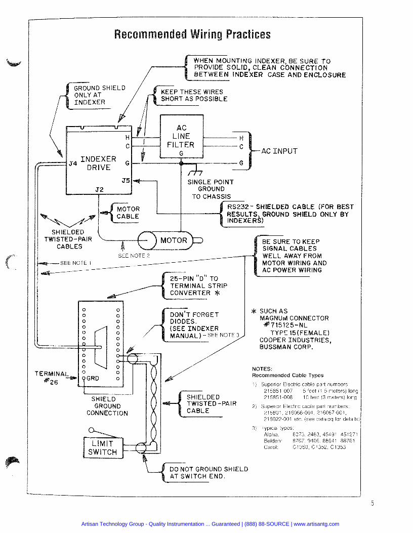
WHEN MOUNTING EXER, BE SURE TO PROVIDE SOLID, AN CONNECTION
E AND ENCLOSU
P THESE WIRES
C INPUT
I I J5 SINGLE POINT I GROUND
S TWI
SEE NOTE 1 SEE NOTE 2
-
BE SURE TO KEEP
OM AND
AC POWER WIRING
U d CONNECTOR
TYPE 15(FEMALE) OOPER INDUSTRIES, USSMAN CORP.
NOTES: Recommended Cable Types
1) Superior Electr~c cable part numbers 215851 007 5 feet (1 5 meters) Ions 21 5851 008 10 feet (3 meters) long
2) Superior Electric cable part numbers 215801 216066 001 216067 001 216022 001 etc (see catalog for details
3) Typ~cal types Alpha 6073 2463 45491 451271 Belden 8767 9406 88641 88761 Carol C1350 C1352 C1353
Artisan Technology Group - Quality Instrumentation ... Guaranteed | (888) 88-SOURCE | www.artisantg.com
IV Wiring Practices - "Dos and Don'ts"
Do the folloviing when installing or wiring your drive or indexer
* Do keep the drive and its wiring as far away from noise sources as possible
4 Do provide a good solid ground connection to the ac system earth ground conductor Bond thedrive case to the system en- closure Do use a srngle-point grounding scheme for ail related corn- ponents of a system (this looks like a hub and spokes ar- rangement) Do keep the ground connection short and direct
* Do use a line filter on the ac input (Corcorn type 10B1 10S1 or lOK1 or e q w a l e n t ) for noisy ac lines Particularly bad ac lines inay need t o be conditioned with a ferroresonant type isolation transformer to provide clean power to the drive o r indexer Do keep signal and drive wiring well separated If the wires inust cross they should do so at right angles to minimize cou- pling Power wiring includes ac wiring motor wiring etc and srgnal wir ing includes inputs and outputs (110) serial coinrnu- nicatrons (RS232 lines) etc
* Do use separate conduits or ducts for signal and I10 wiring Keep all power wir ing out of these signal line conduits
* Do use shielded twisted-pair cables for indexer 110 lmes * Do ground shields only at one end the indexer idr i~e end * Do use twisted-pair shielded cable for the motor wir ing * Do use solid-state relays instead of electromechanical contact
types wherever possible to minimize noise generat~on * Do suppress all relays to prevent noise generation Typical
suppressors are capacitors or M O V s See manufacturers lrterature for complete information
Do not do the following when installing your drive or indexer:
Do not install sensitive computer-based equipment (such as an indexer1drive) near a source of electromagnetic noise.
* Do not bundle power and signal lines together. * Do not bundle motor cables and signal lines together. * Do not fail to use shielded. twisted-pair cables for signals.
Do not fail to properly connect the system grounds. * Do not use "daisy-chained" grounds. * Do not fail to ground signal cable shields at only one end. * Do not assume that power f rom the ac line is adequately
"clean".
Artisan Technology Group - Quality Instrumentation ... Guaranteed | (888) 88-SOURCE | www.artisantg.com
V AC Line Filter
Use of an AC lhne filter on 31 80 and 61 80 Ser~es drlves is recommended. Asuitable filter is included with each unit supplied for sale in North America.
Proper installation of the AC Line Filter is essential
WARNING: Improper installation of the ac l ine filter may cause electrical shock, which could result in death, serious bodily injury or property damage. To avoid electrical shock:
*The ac l ine filter must be installed by qualified personnel. Typical methods of locating and installing the l ine filter are shown in Figures 1 and 2.
*The ac l ine filter must be firmly fastened near the Indexer. Failure to do so may result in damage to the filter and system.
*The installer must properly insulate and protect the ac connections to assure that the wires are not exposed. Exposed wires could cause electrical shock, resutting in death, bodily injury or property damage.
If you have any questions regarding installation of the line filter, contact an electrician before installing the device.
For best performance:
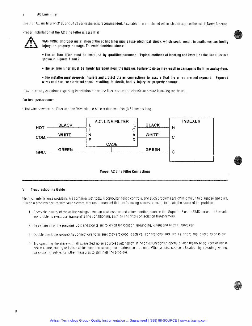
* The wlre between the Filter and the Drive should be less than two feet (0.61 meter) long
Proper AC Line Filter Connections
VI Troubleshooting Guide
Electrical interference problems are common with today's computer-based controls, and such problems are often difficult to diagnose and cure. If such a problem occurs with your system. it is recommended that the fol lowing checks be made to locate the cause of the problem.
1 . Check the quality of the ac line voltage using an oscilloscope and a line monitor. such as the Superior Electric VMS series. If l inevolt- age problems exist, use appropriate line conditioning, such as line filters or isolation transformers.
2 . Be certaln all of the previous Do's and Don'ts are followed for location, grounding, w r i n g and relay suppression
3. Double check the grounding connections to be sure they are good electrical connections and are as short and direct as possible.
4 Try operating the drive wlth all suspected noise sources switched off If the drlve functions properly switch the noise sources on again one at a t ime and try to Isolate whlch ones are causing the Interference problems When a noise source is located try rerouting wir lng suppressing relays or other measures to eliminate the problem
Artisan Technology Group - Quality Instrumentation ... Guaranteed | (888) 88-SOURCE | www.artisantg.com
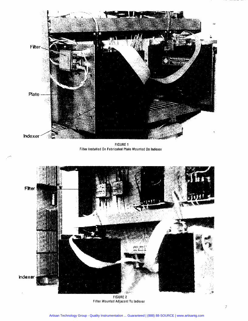
FIGURE 1 Filter installed On Fabricated Plate Mounted On Indexer
FIGURE 2 Filter Mounted Adjacent To Indexer
Artisan Technology Group - Quality Instrumentation ... Guaranteed | (888) 88-SOURCE | www.artisantg.com
PAGE PAGE
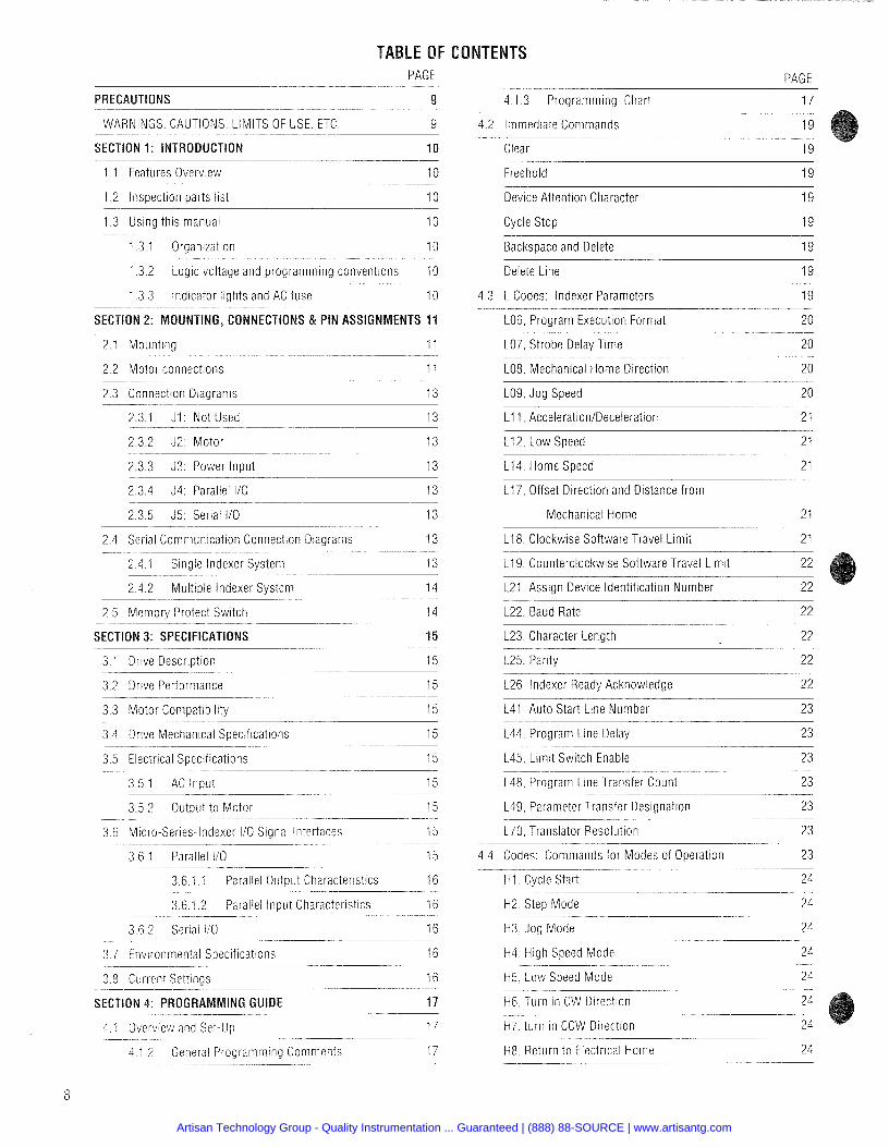
PRECAUTIONS 9 4.1.3 Programming Chart ~ -- -- -.-
1 7
4.2 Immediate Commands -
1 9
Clear 1 9
WARNINGS CAUTIONS. LIMITS OF USE. ETC 9
SECTION 1: INTRODUCTION
1.1 Features Overview 1 0 Freehold 1 9
1 .2 Inspection parts list 10 Device Attention Character 1 9
1.3 Using this manual 1 0 Cycle Stop 1 9
1.3.1 Organization 10 Backspace and Delete 1 9
1.3.2 Logic voltage and programming conventions 1 0 Delete Line 1 9
1.3.3 Indicator lights and AC fuse 1 0 4.3 L Codes: Indexer Parameters 1 9
SECTION 2: MOUNTING, CONNECTIONS & PIN ASSIGNMENTS 11 L06, Program Execution Format
2.1 Mounting 11 107, Strobe Delay Time 20
2.2 Motor connections 11 L08, Mechanical Home Direction 20
2.3 Connection Diagrams 1 3 L09, Jog Speed 20
2.3.2 J2: Motor 1 3 L1 2. Low Speed 2 1
2.3.3 J3: Power lnuut 13 L14, Home Speed 2 1
2.3.4 34: Parallel 110 . .. -- - -. --
13
2.3.5 J5: Serial 110 13
117, Offset Direction and Distance f rom
Mechanical Home 21
L18, Clockwise Software Travel Limit 2 1 2 4 Serial Communication Connection Diagrams - -
2 4 1 Single lndexer System 119. Counterclockwise Software Travel Limit
2 4 2 Multiple lndexer System - -- -
2 5 Memory Protect Switch
L21. Assign Device Identification Number
L22, Baud Rate 22
SECTION 3: SPECIFICATIONS 15 L23, Character Length 22
3 1 Drive Description -- -
15
3 2 Drive Performance -- - - -- -- -
15
3 3 Motor Compatibility -- - ---
15
3 4 Drive Mechanical Specifications 15
L25, Parity 2 2
126, Indexer Ready Acknowledge 22
141, Auto Start Line Number 2 3
L44 Program Line Delay --
2 3
L45 Limit Switch Enable 23 3.5 Electrical Specifications 15
3 5 1 AC lnput -
3 5 2 Output to Motor
L48. Program Line Transfer Count 2 3
L49, Parameter Transfer Designation -.
2 3
170, Translator Resolution 23 -
3 6 Micro-Series-Indexer 110 Signal Interfaces -- - -- --
3 6 1 Parallel I10 4 4 Codes Commands for Modes of Operation -- - - - - - - - - -
H I Cycle Start 3 6 1 1 Parallel Output Characteristics 1 6
3 6 1 2 Parallel lnput Characteristics -- --
1 6 -
3 6 2 Serial I10 1 6
H2 Step Mode
H3 Jog Mode
3.7 Environmental Specifications 1 6 H4. High Speed Mode 24
3 8 Current Settings - - -
1 6
GUIDE - --
17 - --
- - -- 17
4 1 2 General Programming Comments 17
H5. Low Speed Mode 24
H6. Turn in CW Direction
H i . turn in CCW Direction
H8 Return to Electrical Home 24
Artisan Technology Group - Quality Instrumentation ... Guaranteed | (888) 88-SOURCE | www.artisantg.com
G36 Strobe X Code Data
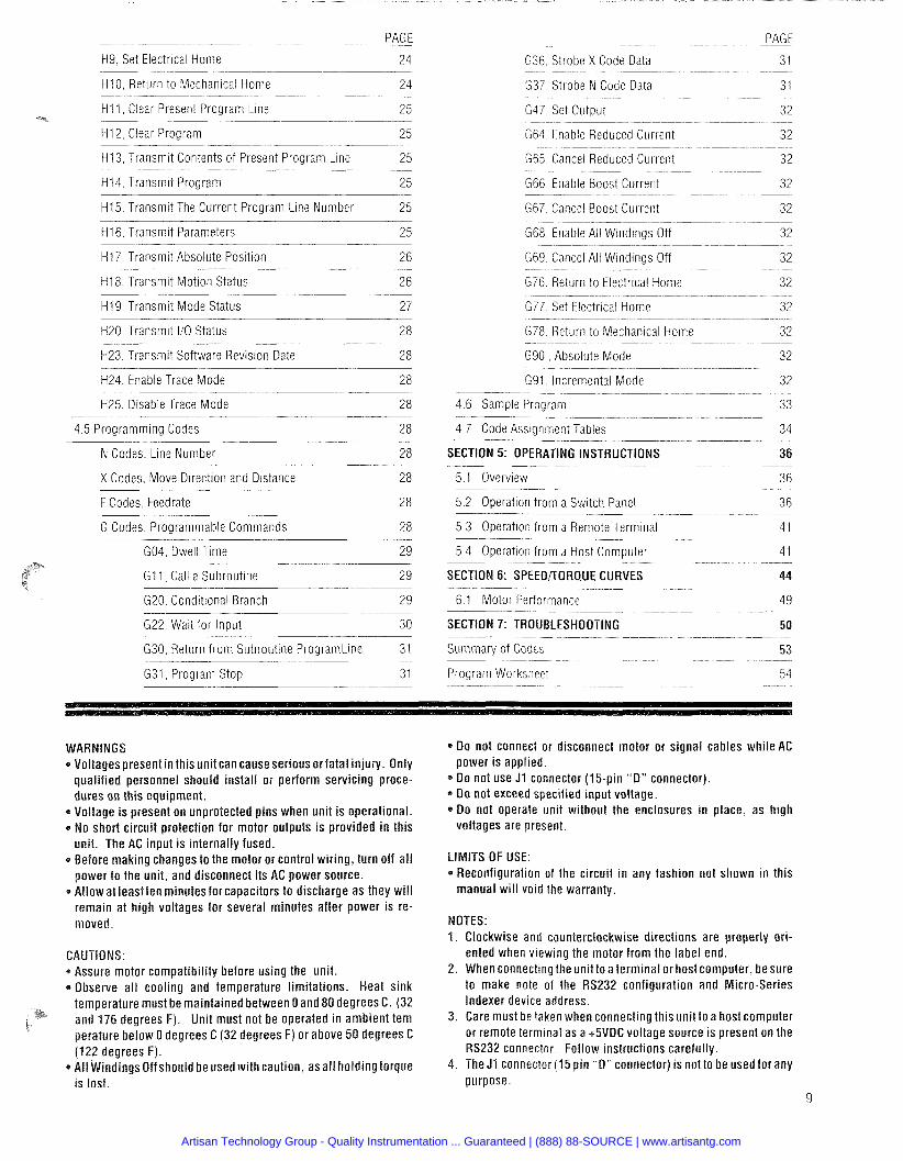
PAGE ---
31 H9, Set Electr~cal Home - --
24 --
H I 0 Return to Mechanical Home 24 G37 Strobe N Code Data 31
H I 1, Clear Present Program Line 25 G47 Set Output 3 2
H I 2. Clear Program 25 G64 Enable Reduced Current - ---
32 - -
G65 Cancel Reduced Current 3 2 H13. Transmit Contents of Present Program L~ne 2 5
H I 4 Transm~t Program -. -- -
25 .-
H15, Transmit The Current Program Line Number 25
G66 Enable Boost Currerlt 32
G67 Cancel Boost Current 32
H16, Transmit Parameters 25 G68 Enable All Wmdings Off -- -
32
G69 Cancel All Windings Off 32 H17, Transmit Absolute Position 26
H I 8, Transmit Motion Status 2 6 G76 Return to Electrical Home - - -- -- -
3 2 -
G77 Set Electrical Home 32 H I 9, Transmit Mode Status 2 7
H20, Transmit I/O Status 28
H23, Transmit Software Revision Date 2 8
G78 Return to Mechanical Home - - -
3 2 - - --
G90 Absolute Mode 32
H24, Enable Trace Mode 28 G91, Incremental Mode 32
H25, Disable Trace Mode 28 4.6 Sample Program 33
4 5 Programming Codes --
2 8 -
N Codes Line Number 28
4.7 Code Assignment Tables 34
SECTION 5: OPERATING INSTRUCTIONS 36
X Codes, Move Direction and Distance 28 5 1 Overview - - -
5 2 Operation from a Sw~tch Panel F Codes, Feedrate
5.3 Operation from a Remote Terminal 4 1 G Codes Programmable Commands - -
28 --
GO4 Dwell Time 29 -
GI 1 Call a Subrout~ne -- --
29
G20 Conditional Branch - -
29 --
G22 Wait for Input 30
5.4 Operation from a Host Computer
SECTION 6: SPEEORORQUE CURVES
6.1 Motor Performance 49
SECTION 7: TROUBLESHOOTING 50
G30, Return from Subroutine ProgramLine 31 Summary of Codes - -- -
53 - - -
Program Worksheet 54 G31. Program Stop 3 1
* D o not connect or disconnect motor or signal cables while AC power is applied.
* 0 0 not use J1 connector (15-pin "0 " connector). * Do not exceed specified input voltage. * D o not operate unit without the enclosures in place, as high
voltages are present.
WARNINGS * Voltagespresent in this unit can causeserious or fatal injury. Only
qualified personnel should install or perform servicing proce- dures on this equipment.
* Voltage is present on unprotected pins when unit is operational. a No short circuit protection for motor outputs is provided in this
unit. The AC input is internally fused. * Before making changes to the motor or control wiring, turn off a l l
power to the unit, and disconnect its AC power source. * Allow at least ten minutes for capacitors to discharge as they wil l
remain at high voltages for several minutes after power is re- moved.
LIMITS OF USE: * Reconfiguration of the circuit in any fashion not shown in this
manual wi l l void the warranty.
NOTES: 1. Clockwise and counterclockwise directions are properly ori-
ented when viewing the motor from the label end. 2. When connecting the unit to a terminal or host computer, be sure
to make note of the RS232 configuration and Micro-Series Indexer device address.
3. Care must be taken when connecting this unit to a host computer or remote terminal as a +5VDC voltage source is present on the RS232 connector. Follow instructions carefully.
4. The J1 connector (15 pin "D" connector) is not to be used for any purpose.
9
*Assure motor compatibility before using the unit. *Observe al l cooling and temperature limitations. Heat sink
temperature must be maintained between Oand 80 degrees C. (32 and 176 degrees F). Unit must not be operated in ambient tern perature below 0 degrees C (32 degrees F) or above 50 degrees C (122 degrees F).
* All Windings Off should be used with caution, asa l l holding torque is lost.
Artisan Technology Group - Quality Instrumentation ... Guaranteed | (888) 88-SOURCE | www.artisantg.com
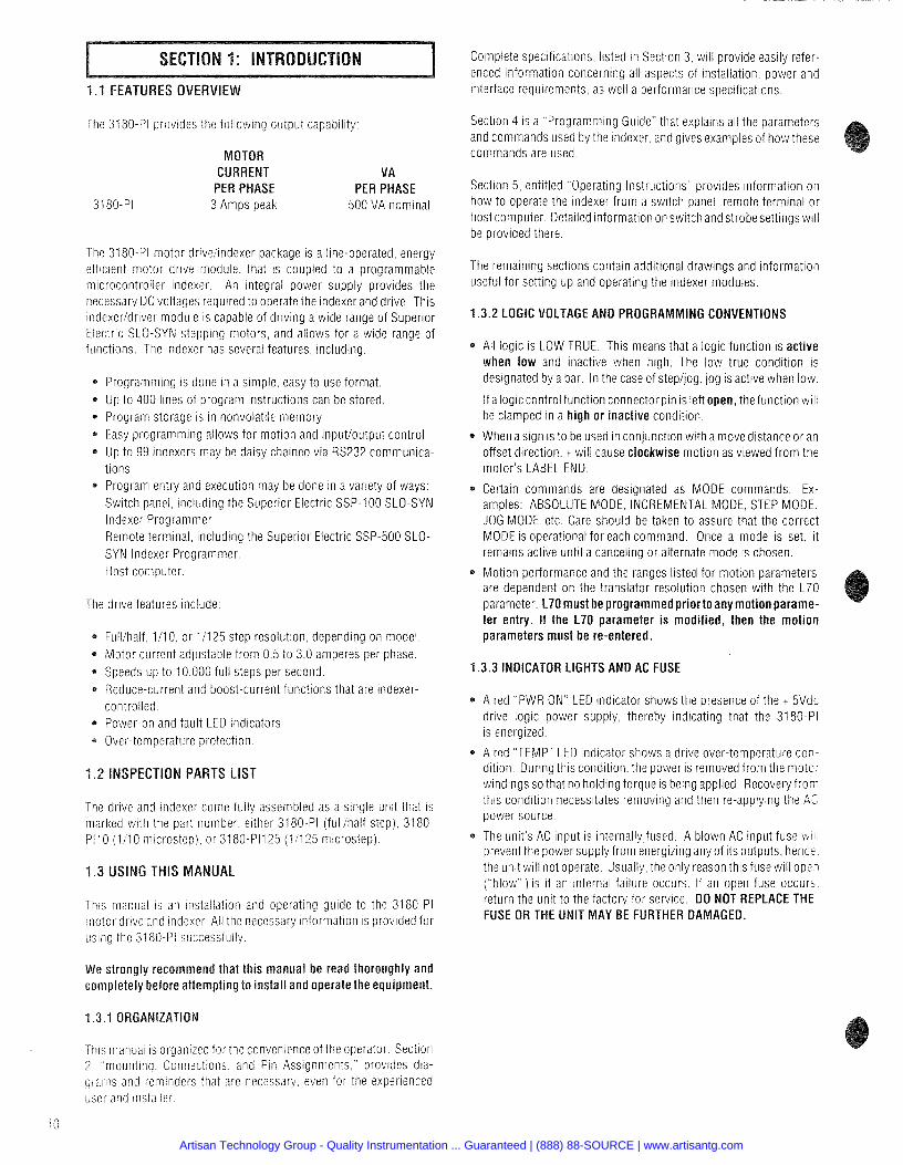
1.1 FEATURES OVERVIEW
The 3180-PI provides the following output capability:
MOTOR CURRENT VA
PER PHASE PER PHASE 3180-PI 3 Amps peak 500 VA nominal
The 3180-PI motor drivelindexer package is a line-operated, energy efficient motor drive module, that is coupled to a programmable m~crocontrol ier indexer. An integral power supply provides the necessary DC voltages required to operate the indexer and drive. This indexeridriver module is capable of driving a wide range of Superior Electric SLO-SYN stepping motors, and allows for a wide range of functions, The indexer has several features, including:
Programming is done in a s ~ m p l e easy to use format Up to 400 lines of program instructions can be stored Program storage is in nonvolatile memory Easy programming allows for motion and input/output control Up to 99 indexers may be daisy chained via RS232 communica- tions Program entry and execution may be done in a variety of ways Switch panel including the Superior Electric SSP-100 SLO-SYN lndexer Programmer Remote terminal including the Superlor Electric SSP-500 SLO- SYN Indexer Programmer Host computer
The drive features include.
Full/half 1/10 or 11125 step resolution depending on model Motor current adjustable f rom 0 5 to 3 0 amperes per phase
* Speeds up to I 0 000 full steps per second * Reduce-current and boost-current functions that are indexer-
controlled * Power-on and fault LED indicators * Over-temperature protection
1.2 INSPECTION PARTS LIST
The drive and indexer come fully assembled as a single unit that is inarked with the part number either 3180-PI (fullihalf step) 3180- PI10 (1110 microstep) or 3180-PI125 (11125 microstep)
1.3 USING THIS MANUAL
This manual is an installation and operating guide to the 3180-PI motor drive and indexer All the necessary information is provided for using the 3180-Pi successfully
We strongly recommend that this manual be read thoroughly and completely before attempting to install and operate the equipment.
1.3.1 ORGANIZATION
Complete specifications listed in Section 3 will provide easily refer- enced information concerning all aspects of installation power and interface requirements as well a performance specifications
Section 4 is a Programmrng Guide' that explains all the parameters and commands used by the indexer and gives examples of how these commands are used
Section 5 entitled Operating Instructions provides information on how to operate the indexer f rom a switch panel remote terminal o r host computer Detailed information on switch and strobesettings wil l be provided there
The remaining sections contain additional drawings and information useful for setting up and operating the indexer modules.
1.3.2 LOGIC VOLTAGE AND PROGRAMMING CONVENTIONS
All logic is LOW TRUE. This means that a logic function is active when low and inactive when high. The low true condition is designated by a bar. In the case of step/Eg, jog is active when low.
If a logiccontrol function connectorpin is left open, the function wil l be clamped in a high or inactive condition.
When a sign is to be used in conjunction with a move distance or an offset direction. + will cause clockwise motion as viewed f rom the motor's LABEL END.
Certain commands are designated as MODE commands. Ex- amples: ABSOLUTE MODE. INCREMENTAL MODE, STEP MODE. JOG MODE, etc. Care should be taken to assure that the correct MODE is operational for each command. Once a mode is set. i t remains active until a canceling or alternate mode is chosen.
Motion performance and the ranges listed for motion parameters are dependent on the translator resolution chosen with the L70 parameter. L70 must be programmed priorto any motionparame- ter entry. If the L70 parameter is modified, then the motion parameters must be re-entered.
3.3 INDICATOR LIGHTS AND AC FUSE
A red "PWR ON" LED indicator shows the presence of the t 5Vdc drive logic power supply. thereby indicating that the 3180-PI is energized.
A red "TEMP" LEO indicator shows a drive over-temperature con- dition. During this condition. the power is removed from the motor v~indings so that no holding torque is being applied. Recovery f rom tlirs condition necessitates removing and then re-applying the AC power source.
The unit s AC input is internally fused A blown AC input fuse w I prevent the power supply f rom energizing any of its outputs hencs the unit will not operate Usually theonly reason thlsfuse will ope? ( blow ) is if an internal failure occurs If an open fuse occurs return the unit to the factory for service DO NOT REPLACE THE FUSE OR THE UNIT MAY BE FURTHER DAMAGED.
This inianuai is organized for the convenience of the operator Section 2 mounting Connections and Pin Assignments provides dia- grai i is and reminders that are necessary even for the experienced user and iiistaller
Artisan Technology Group - Quality Instrumentation ... Guaranteed | (888) 88-SOURCE | www.artisantg.com
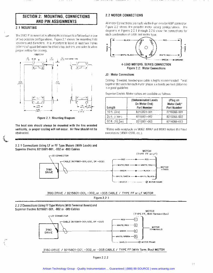
The 31 80-PI is mounted by afflxing ~ t s enclosure to af lat surface in one of two possible configurations Figure 2 1 shows the mounting hole locations and diameters It is important to leave at least two inches (51 rnm) of space between the drive s t o p bottom and sides to allow
2.2 MOTOR CONNECTIONS
All motor Connectioris are made vla the 8-pin circular AMP connector. Figure 2.2 shows the possible rnotor wiring configurations. The diagrarns in Figures 2.2.1 through 2.2.6 show the connections for each comblnatiori of cable and motor type
BLACK
m a w
WHlTElBLACK
-QUEEN -+ QRWND
4-LEA0 MOTORS, SERIES CONNECTION Figure 2.2: Motor Connections
J2: Motor Connections
Cabling: Shielded. twisted-par cable IS highly recommended. T w ~ s t together the wlres for each motor phase; six twists per foot (305mm) IS a good guideline.
Superior Electric Motor cables are available as follows.
(Unterminated Leads On Motor End)
Figure 2.1: Mounting Diagram
(Plug on Motor End)*
Length
The heat sink should always be mounted with the fins oriented vertically, or proper cooling wi l l not occur. Air flow should not be
Part Number I Part Number
*Mates wlth receptacle on M062, M062 and M063 motors that have receptacles (M061 -CS08. etc )
2.2.1 Connections Using LF or FF Type Motors (With Leads) and Superior Electric 8215801-001, -002 or -003 Cables
l o f t (3m)
MOTOR
821 5801 -001 1 B216066-001
ZCONNECTOR (TYPE FF or L F )
RED -RED CABLE (8215801-001;002, OR -003)
TE/RED b W H I T E / R E D -
GREEN -BLAC
WHITE/GREEN --+--- WHITE/BLA
SHIELD-@ MOTOR FRAME
3180 DRIVE / 8215801-001, -002, or - 0 0 3 CABLE / TYPE FF or L F MOTOR
Figure 2.2.1
2.2.2 Connections Using FFType Motors (With Terminal Boxes) and Superior Electric B215801-001, -002 or -003 Cables
MOTOR (TYPE FF, With Terminal Box)
2 CONNECTOR
CABLE (8215801-001;002, OR -003)
MOTOR TERMINALS
WHITE/QREEN
SHIELD ~-0 MOTOR FRAME
3180 DRIVE / 8215001-001, -002,or - 0 0 3 CABLE / TYPE FF (With Term. Box) MOTOR
Figure 2.2.2
Artisan Technology Group - Quality Instrumentation ... Guaranteed | (888) 88-SOURCE | www.artisantg.com
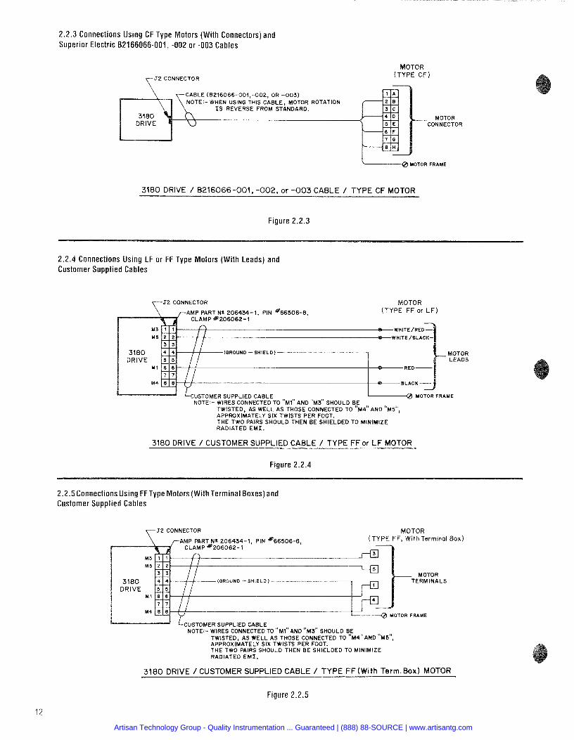
2.2.3 Connections Using CF Type Motors (With Connectors) and Superior Electric 82166066-001, -002 or -003 Cables
CABLE (8216066-001,-002, OR -003)
OTOR (TYPE CF)
- MOTOR CONNECTOR
3180 DRIVE / B216066-001, -002, or -003 CABLE / TYPE CF MOTOR
Figure 2.2.3
2.2.4 Connections Using LF or FF Type Motors (With Leads) and Customer Supplied Cables
2 CONNECTOR MOTOR AMP PART N r 206434-1, PIN "66506-8, (TYPE FF or LF)
CLAMP *206062-1
(GROUND -SHIELD MOTOR LEADS
L----------d LCUSTOMER SUPPLIED CABLE I-0 MOTOR FRAME NOTE:- WIRES CONNECTED TO " ~ 1 " AND " ~ 3 " SHOULD BE
TWISTED, AS WELL AS THOSE CONNECTEO TO " ~ 4 ' ' AND "M5", APPROXIMATELY SIX TWISTS PER FOOT. THE TWO PAIRS SHOULD THEN BE SHIELDED TO MINIMIZE RADIATED E M I .
3180 DRIVE / CUSTOMER SUPPLIED CABLE / TYPE FF or L F MOTOR
Figure 2.2.4
2.2.5 Connections Using FFType Motors (With Terminal Boxes) and Customer Supplied Cables
F, Wi th Terminal Box)
MOTOR FRAME
NOTE:- WIRES CONNECTEO TO "Ml" AND " ~ 3 " SHOULD BE TWISTED, AS WELL AS THOSE CONNECTED TO "M4"AND "M5", APPROXIMATELY SIX TWISTS PER FOOT. THE TWO PAIRS SHOULD THEN BE SHIELDED TO MINIMIZE RADIATED E M I .
3180 DRIVE / CUSTOMER SUPPLIED CABLE / TYPE FF(With Term.Box) MOTOR
Figure 2.2.5
Artisan Technology Group - Quality Instrumentation ... Guaranteed | (888) 88-SOURCE | www.artisantg.com
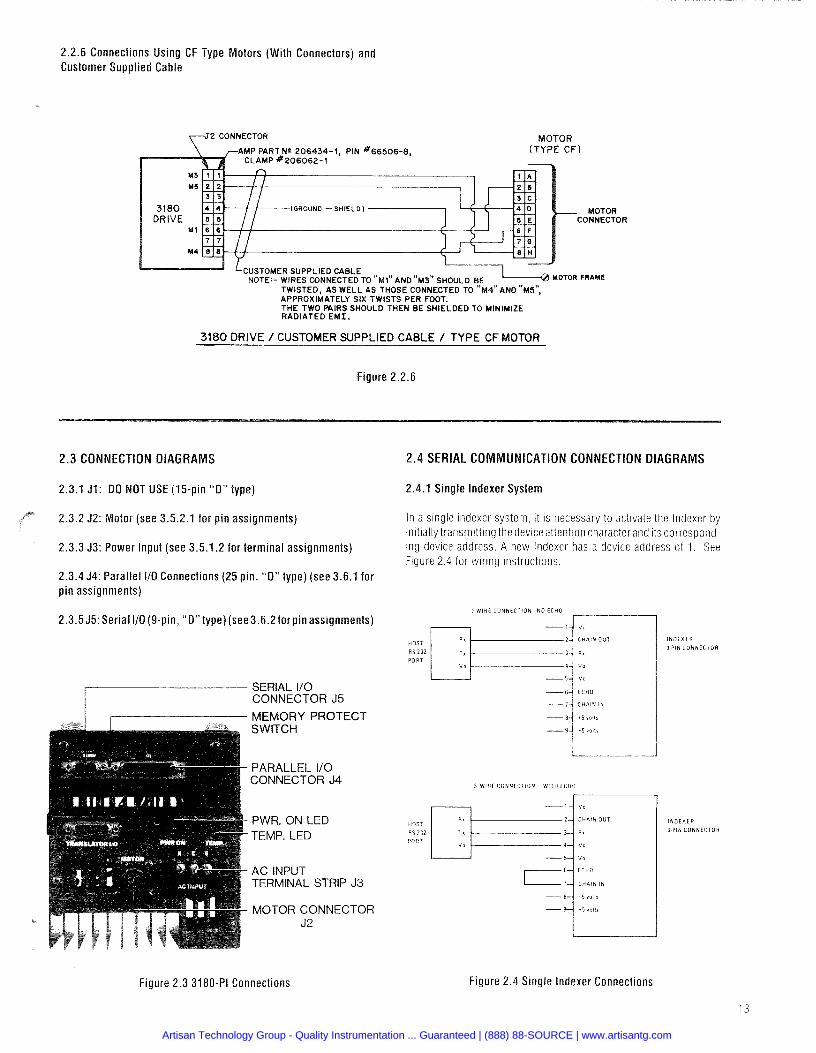
2.2.6 Connections Using CF Type Motors (With Connectors) and Customer Supplied Cable
2 CONNECTOR
GROUND -SHIELD)
LcusToMER SUPPLIED CABLE ' 7 L o I o R rmw NOTE:- WIRES CONNECTED TO " ~ 1 " AND " ~ 3 " SHOULD BE
TWISTED, AS WELL AS THOSE CONNECTED TO " ~ 4 " AND "M5", APPROXIMATELY SIX TWISTS PER FOOT. THE TWO WlRS SHOULD THEN BE SHIELDED TO MINIMIZE RADIATED E M I .
3180 DRIVE / CUSTOMER SUPPLIED CABLE / TYPE CF MOTOR
Figure 2.2.6
2.3 CONNECTION DIAGRAMS
2.3.1 J1: DO NOT USE (15-pin "0 " type)
otor (see 3.5.2.1 for pin assignments)
2.3.3 53: Power Input (see 3.5.1.2 for terminal assignments)
2.3.4 J4: Parallel I10 Connections (25 pin. "0 " type) (see 3.6.1 for pin assignments)
2.4 SERIAL COMMUNICATION CONNECTION DIAGRAMS
2.4.1 Single lndexer System
2.3.5 55: Serial IlO(9-pin, "0 " type)(see3.6.2forpinassignments)
HOST
RS 2 3 2 PORT
SERIAL 110 / CONNECTOR J5
I M E M O R Y P R O T E C T
In a s lng ie ~ndexer s y s t e l n ~t IS necessary t o ac t l va te the lridexer by i n i t ~ a l l y t ransrn l t t l ng the dev~ce attentton character and ~ t s correspond- I n g dev lce address A new indexer has a dev lce address of 1 See F lgure 2 4 for w l r l n g I n s t r u c t t o n s
S W I T C H
3WlRE C O N N t C I l O N NO ECHO
a x
TI
V O
PARALLEL I10 CONNECTOR J4
3 WlR€ CONNECTION WITH ECI i0
I
PWR. O N L E D TEMP. L E D
A C INPUT TERMINAL STRIP J3
MOTOR CONNECTOR J2
INDEXER
9 PIN CONNECTOR
INDEXER
9 PIN CONNCCTOR
Figure 2.3 3180-PI Connections Figure 2.4 Single Indexer Connections
Artisan Technology Group - Quality Instrumentation ... Guaranteed | (888) 88-SOURCE | www.artisantg.com
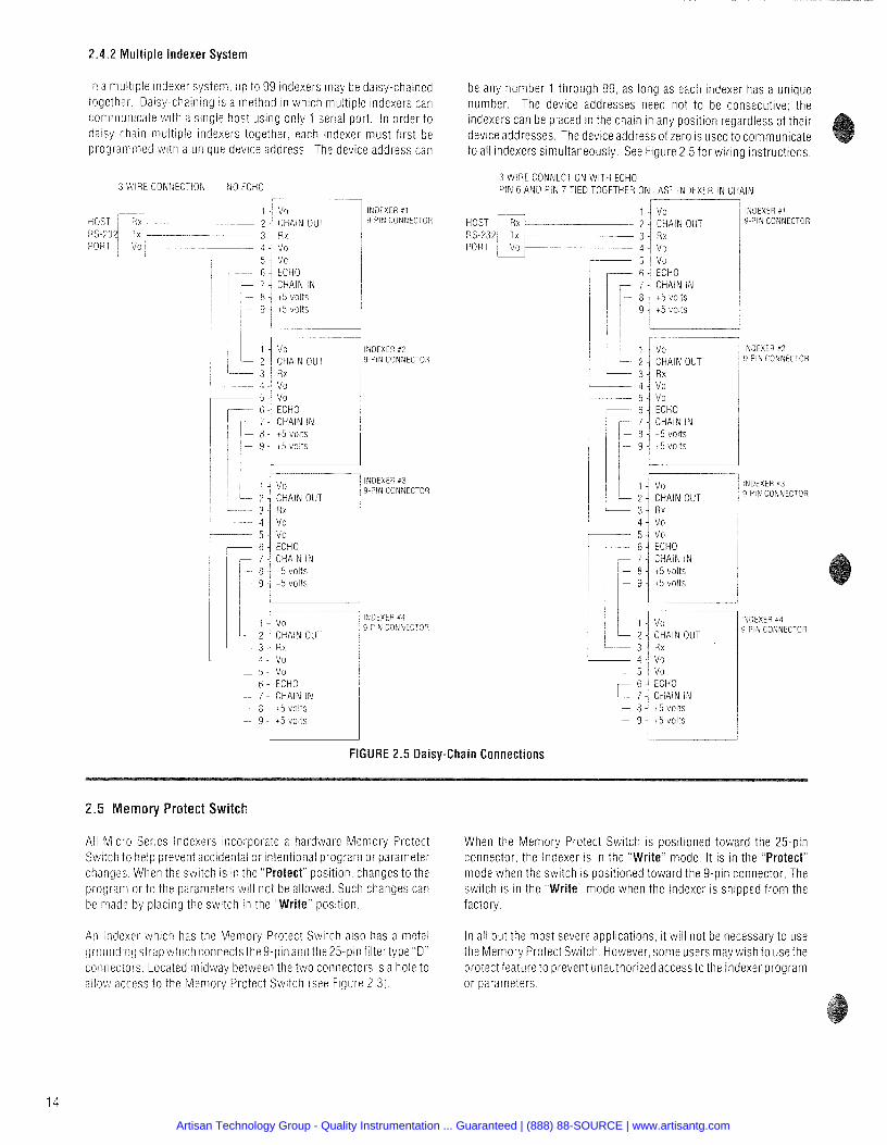
2.4.2 Multiple lndexer System
In a multiple indexer system. up to 99 indexers may be d a y - c h a i n e d together Dalsy-chaining IS a method in which muhp le indexers can communicate with a singie host uslng only 1 s e r a port. In order to dalsy chaln multiple Indexers together, each indexer must first be progran~med with a unlque device address. The device address can
3 WIRE CONhECTlON NO ECHO 7 - 1
I P d E X E R #I 2. CHAIN OUT I 9 PI4 CONNECTOR
3 - 'Ivo R x - - 4 -I vo i
... 5: vo 1 r--- 6-1 ECHO
7 - CHAIN IN 1 1 c B ! 15 volts I ) - 9 -1 15 volts I l l I I
/ INDEXER 42 / 9 PIN CONNECTOR
I l l - INDEXER #3 9-PIN CONNECTOR
1 INDEXER #4 / 9-PIN CONNECTOR
l I I i
:
I r--
- - 3 - R r
4 - vo
be any number 1 through 99, as long as each indexer has a unique number. The device addresses need not to be consecutive; the Indexers can be placed ~n the cnain in any position regardless of their device addresses. The device address of zero is used to communicate to all indexers simultaneously. See Figure 2.5 for wiring instructions.
- 5 - - - 6 -
3 WIRE CONNECTION WITH ECHO PIN 6 AND PIN 7 TIED TOGETHER ON LAST INDEXER IN CHAIN
vo ECHO
1 4 vo INDEXER pl HOST I%--.- --- 2 ' CHAIN OUT 9-PIN CONNECTOR RS-232, Tx t 3 1 R x
-- 7 4 CHAIN IN - 8 -/ 15 volts - 9 -i 45 volts
1
INDEXER #3 9-PIN CONNECTOR
FIGURE 2.5 Daisy-Chain Connections
t5 volts 15 volts
INDEXER #4 9-PIN CONNECTOR
emory Protect Switch
Ali Micro Series Indexers Incorporate a hardware Memory Protect When the Memory Protect Switch is positioned toward the 25-pin Switch to help prevent accidental or intentional program or parameter connector, the lndexer is in the "Write" mode. I t is in the "Protect" changes. When the swltch IS in the "Protect" position. changes to the mode when the switch IS positioned toward the 9-pin connector. The program or to the parameters will not be allowed. Such changes can switch is in the "Write" mode when the lndexer is shipped f rom the be made by placing the swltch in the "Write" position. factory.
An Indexer whlch has the Memory Protect Swltch also has a metal in all but the most severe applications ~t will not be necessary to use grounding strap w h c h connects the 9-pin and the 25-pin filtertype D ' the Memory Protect S~v i t ch However some users may wlsh to use the connectors Located midway between the two connectors 1s a hole to protect feature to prevent unauthorized access to the lndexer program allov! access to the Memory Protect Switch (see Figure 2 3) or parameters
Artisan Technology Group - Quality Instrumentation ... Guaranteed | (888) 88-SOURCE | www.artisantg.com
3.5 ELECTRICAL SPECIFICATIONS 3.5.1 AC lnput
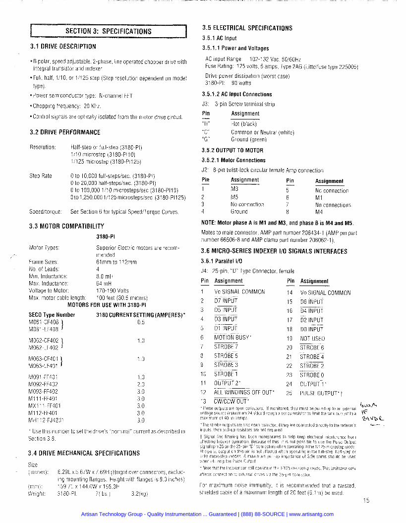
3.1 DRIVE DESCRlPTlO 3.5.1.1 Power and Voltages
AC lnput Range: 102-1 32 Vac. 50160Hz Fuse Rating: 125 volts, 5 amps, Type 2AG (Littelfuse type 225005)
* Blpolar, speed adjustable, 2-phase. line operated chopper drive with integral translator and indexer.
*Full, half, 111 0, or 111 25 step (Step resolution dependent on model
type).
Drive power dissipation (worst case) 3180-PI: 90 watts
3.5.1.2 AC lnput Connections P o w e r semiconductor type: N-channel FET J3: 3-pin Screw terminal strip *Chopping frequency: 20 Khz. Pin - Assignment
"H" Hot (black) "C" Common or Neutral "G" Ground (green)
*Control signals are optically isolated from the motor drive circuit.
3.2 DRIVE PERFORMANCE (white)
Resolution: Half-step or full-step (3180-Pi) 1/10 microstep (3180-PI1 0) 11125 microstep (3180-P1125)
3.5.2 OUTPUT TO MOTOR
3.5.2.1 Motor Connections
J2: 8-pin twist-lock circular female Amp connection Step Rate: 0 to 10,000 full-stepsisec. (3180-PI)
0 to 20,000 half-stepsisec. (3180-PI) 0 to 100,000 111 0 microstepsisec (3180-P110) Oto 1,250,000 11125 microsteps1sec. (3180-PI1 25)
Pin - Assignment - Pin Assignment 1 M3 5 No connection 2 M 5 6 M 1 3 No connection 7 No connectioils 4 Ground 8 M4 Speeditorque: See Section 6 for typical SpeedDorque Curves
NOTE: Motor phase A is M I and M3, and phase B is M4 and M5.
Mates to male connector, AMP part number 206434-1 (AMP pin part number 66506-8 and AMP clamp part number 206062-1).
Motor Types: Superior Electric motors are recom- mended
Frame Sizes: 61 m m to 112mm No. of Leads: 4 Min. Inductance: 8.0 mH Max. Inductance: 64 mH Voltage to Motor: 170-1 90 Volts Max. motor cable length: 100 feet (30.5 meters)
MOTORS FOR USE WITH 3180-PI
SECO Type Number 3180 CURRENTSETTING (AMPERES)* M061 -CF408 1 0.5 M061 -LF408
DEXER I10 SIGNALS I 3.6.1 Parallel 110
J4: 25-pin, "D" Type Connector, female
Pin Assignment - 1 Vo SIGNAL COMMON
2 07 INPUT --
3 D5 INPUT
4 03 INPUT
Pin Assignment
VO SIGNAL COMMON -- D6 INPUT - -- D4 INPUT --
D2 INPUT -- -
DO INPUT
NOT USED -- STROBE 6
STROBE 4
STROBE 2 -- STROBE 0
5 D l INPUT --
6 MOTION BUSY * --
7 STROBE 7
8 STROBE 5
9 STROBE 3
10 STROBE 1 M091 -FF401 M092-FF402 M093-FF402 M I 11 -FF401 MX l 1 1 -FF401 M1 12-FF401 MHI 12-FJ4201
--
11 OUTPUT2* 24 OUTPUT 1 "
12 ALL WINDINGS OFF OUT* 25 PULSE OUTPUT*^
13 CWiCCW OUT* in m.,f+- 'These outputs are open collectors I f monitored they must be pulled up to an external mltage source (maximum 24 Vdc) through a series resistor to limit the sink current to a \F maximum of 40 milliamps
'The strobe outputs are also open coliector, i f they are conrlected directly to l h e indexers ---- inputs then pull-up resistors are not required
t Signal line filtering has been incorporated to help keep electrical interference from affecting Indexer operation Because of this, i t is not possibie to use the Pulse Output signai (pin 25 on the 25-pin ' D" connector) when operating in the 1:125 microstep mode The puise output on this pin is not affected when operatinq in the full-step half-step or 1/10 microstep modes A maximum piiil-up impedance of 3 9k ohriis should be used vihen utilizing the Puise Outpu!
t Note that the Indexer can still operate in the 11125 microstep mode This lirnitation only
affects connection to external dri'des via the 25-pin connector
* Use this number to set the drlve's "nominal" current as described in Section 3 8
Size (inches)
i m m i Weight
MECHANICAL SPECIFICATIONS
6.291 x 5.67W x 7.69H (Height over connectors, exclud- ing mounting flanges. Helght with flanges is 8.0 inches) 159.71 x 144.OW x 195.3H 3180-PI: 7(lbs.) 3.2(kg)
For maximum noise immunity, it IS recommended that a twisted, shielded cable of a maximum length of 20 feet (6.1 m) be used.
15
Artisan Technology Group - Quality Instrumentation ... Guaranteed | (888) 88-SOURCE | www.artisantg.com
3.6.1.1 Parallel Output Characteristics
The f o l l o v ~ ~ n g pertain to Output 1 (Pin 24) Output 2 (Pin 11)
Out (Pin 12) CW CCW Out (Pin 13) % L ~ ( P I ~ 25) ~:t ionX&
(Pin 6) and Strobe 0 through Strobe 7 Outputs
High level output. 124 Vdc max.. open collector High level leakage current: 250 microamps max. Low level output: 1-0.4 Vdc @ 1 6 m A sink current
t 0 . 7 Vdc @ 40 mA sink current
3.6.1.2 Parallel Input characteristics
The following pertain to DO through 0 7 inputs: High level ( inact~ve voltage: t 8 . 5 Vdc min. ; t 15 Vdc max High level current: 1 mil l iamp maximum leakage Low level (active) voltage: 0.0 Vdc mln.: t 6.5 Vdc max. [.ow Level current: 3.5 m i l l i a m ~ max
3.6.2 Serial 110
35 9-Pin "D" Type Coriiiector female
Pin
1 2 3 4 5 6 7 8 9
Assignment
Vo RS-232 CHAIN OUT RS-232 RECEIVE DATA Vo Vo RS-232 ECHO RS-232 CHAIN IN t 5 Vdc t 5 Vdc
Wire size. 24 AWG minimum. Cable with shielded. tw~s ted pairs is higtily recommended.
Ruii length: 50 feet (15.2m) max
Cables available f rom Superlor Electric:
(25 pin D connector on one end 9-pin D connector on other)
Length Part No. 5 ft (1 51n) B216059-001 l o f t (3x1) 821 6059-002
VIRONMENTAL SPECIFICATIONS
Operating Temp t 32 F to t 122 F (0 C to t 5 0 C) Free Air Anibient
Storage Temp - 40 F to t 167 F ( - 40 C to t 7 5 C) Humidity 95% max noncondensing Altitude 1 0 000 feet (3048 meters) max Cooling Wil l operate up to 122 degrees F (50 degrees C)
so long as maximuni heat sink temperature of 176 degrees F (80 degrees C) is maintained forced-air (fan) cooling may be required)
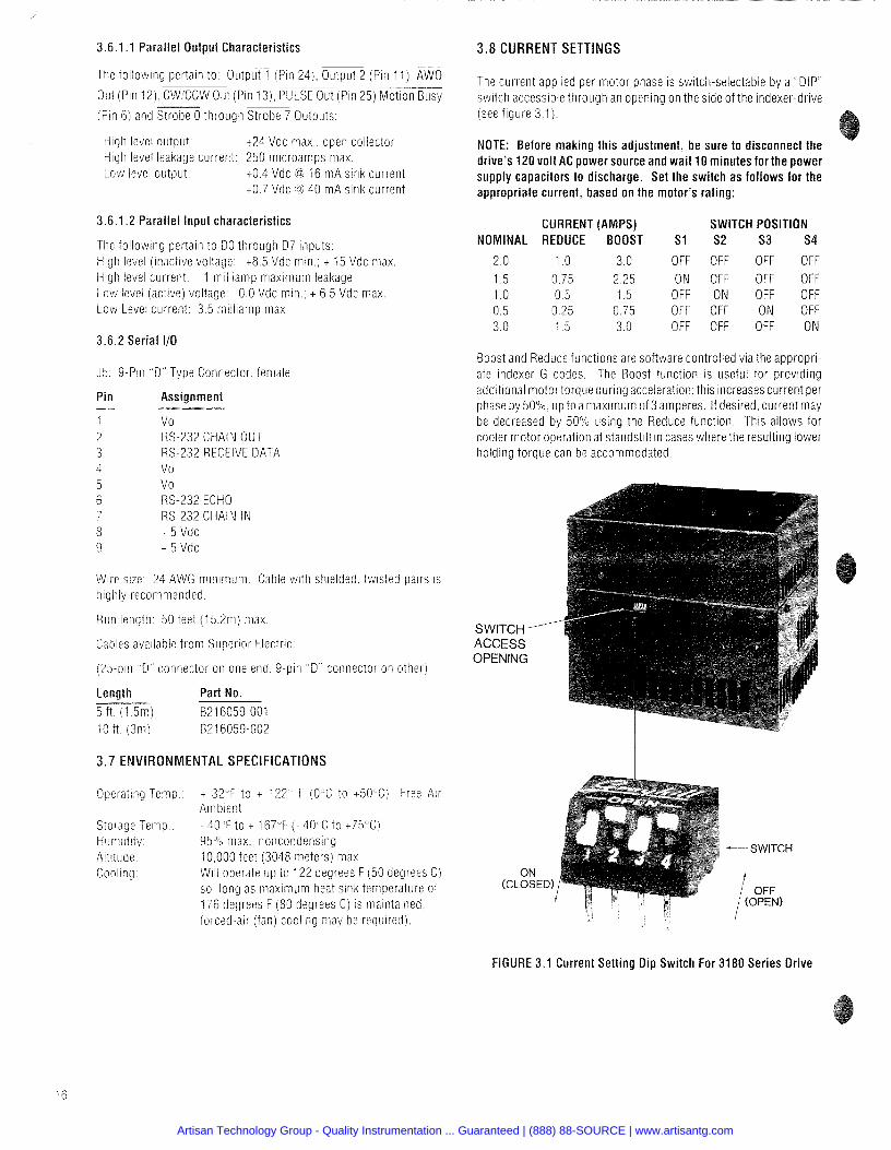
3.8 CURRENT SETTINGS
The current applied per motor phase is switch-selectable by a "DIP" switch accessible through an opening on the s ~ d e of the indexer-drive (see figure 3.1).
NOTE: Before making this adjustment, be sure to disconnect the drive's 120 volt AC power source and wait 10 minutes for the power supply capacitors to discharge. Set the switch as follows for the appropriate current, based on the motor's rating:
CURRENT (AMPS) SWITCH POSITION NOMINAL REDUCE BOOST S1 S2 S3 S4
2.0 1 .O 3.0 OFF OFF OFF OFF 1.5 0.75 2.25 ON OFF OFF OFF 1 .O 0 .5 1.5 OFF ON OFF OFF 0.5 0.25 0.75 OFF OFF ON OFF 3.0 1 .5 3.0 OFF OFF OFF ON
Boost and Reduce functions are software controlled via the appropri- ate Indexer G codes The Boost func t~on IS useful for p r o v ~ d ~ n g additional motor torque during acceleration this increases current per phase by 50% up to a maximum of 3 amperes If desrred current may be decreased by 50% using the Reduce functlon Thls allows for cooler motor operation at standstill in cases where the resulting lower holding torque can be accommodated
S W I T C H - A C C E S S O P E N I N G
FIGURE 3.1 Current Setting Dip Switch For 3180 Series Drive
Artisan Technology Group - Quality Instrumentation ... Guaranteed | (888) 88-SOURCE | www.artisantg.com
This section contains the information necessary to set up, enter, and edit programs and also to execute programs with the Micro Series Indexer.
By carefully reading this section through in its entirety, the user will fully understand the wide range of applications possible with the Micro Series Indexer.
.1 OVERVIEW AN0 SET-U EIA (Electronic Industries Association) Standard RS274-D is the programming guide for numerically controlled machines. Superior Electric has utilized this standard to form the basis for the Micro Series Indexer's command structure. It was not technically desirable to conform to the standard in complete detail, but it proved beneficial in the program structure to perform complex and varied operations with a simple format.
Using straightforward programming formats, the Micro Series lndexer enables the user to program and execute in either parallel (switch panel) or serial (remote terminal or host computer) communication modes.
In general, all parameters and commands can be broadly grouped into four categories, which correspond to these code groupings:
1. L Codes 3. N, G , X and F Codes 2. H Codes 4. Immediate Codes
1. "L Codes" (discussed in Section 4.3) are used to set parameters for each indexer. These commands are not consid- ered part of an indexer program, that i s , they are made prior to any motion programming and do not have program line num bers.
It is important to remember that the L codes are used exclu- sively to set the initial parameters of a particular indexer and should not be thought of as part of the program option for the indexer.
Codes" (Section 4.4) are used to set indexer modes, control manual and program execution and to transmit para- meters and indexer status via the serial communications port. H codes are not part of the programming commands for the indexer. There are no program line numbers associated with the "H" codes and they are not considered to be part of the programming function.
and F Codes" (Section 4.5) are the programming commands for the indexer. Up to 400 lines of program instruc- tions can be stored as a unique motion control program.
Each program is in a fixed format, and is composed of a line number, a "G" code, an "Xu code and an "F" field.
A line of program has this format: N[nnn) G[nn] X[snnnnnnnn] F[nnnnnnn] A space is used to separate the codes. Not all codes need be programmed for each program line. The G, X and F codes may be programmed in any order.
: The brackets, [I, are used in this manual for clarity h,
and are not to be used when entering data or variables
4. lmmediate Codes (Section 4.2) are executed immediately upon receipt and are not stored as part of the program. All commands are highlighted in bold face for easy reference.
4.1.2 General Programming Comments
T PROGRAMMING NOTES**
1. The indexer contains a 40 character serial buffer to accept al l data and programming entries. If a COMMAND TERMINATOR (CARRIAGE RETURN and/or LINE FEED) is not received by the 40th character, the buffer contents art: dumped and that 40 character strina is lost.
Upon receipt of a CR and/or LF, an XOFF (ASCII Code 19) character is transmitted to the host; no further data trans- mission from the host should occur. However, any char- acters transmitted subsequent to XOFF wi l l be stored in the buffer until the buffer capacity is reached. if the capacity is exceeded, the buffer contents are dumped.
The receipt of a COMMAND TERMINATOR character wi l l cause the commands in the buffer to be executed sequen- tially. That is, the first command that was entered wil l be the first command executed. The COMMAND DELIMITER for a series of commands is a space. Once al l the com- mands in the buffer have been executed, the indexer wi l l send an XON (ASCII Code 17) character and wi l l be ready to receive further data.
2. Whether the indexer is being operated from a switch panel, remote terminal or host computer, the first task that faces an operator, after all circuit connections have been made, is that of setting "L: codes", the parameters of each indexer.
3. In the following descriptions, it is important to note the factory default values for each parameter as entry steps can be eliminated. Upon receipt of a new indexer, the default ilalues will have been entered for the parameters.
I . Motor speeds and acceleration will depend on theTRANS- LATOR RESOLUTION setting (L70 nnn). Set this parameter first and then work in ascending numerical order starting @ith the LO6 parameter.
NOTE: If the L70value is changed, the valuesfor L09, L11, L12, L14 and the "F" field values must be reentered.
5. Entry of invalid data for a parameter or program field will -esult in the previous data being left intact.
3. If the number of characters entered exceeds the number ~f required characters, the data is truncated to the maxi- num field length for the entry.
XoniXoff Protocol: The Xoff character is transrnitted to the host when a CR or LF is received The lndexer will process the information it has received and v!iII transmit an Xon character when it is ready to accept more information f rom the host The lndexer should be polled to determine when it is ready to accept more information If L26 3 is selected the lndexer will transmit an = if i t is ready to accept more ~nformat ion If an Xoff chardcter has been transmitted to the host and the command received by the lndexer calls for motion or progrdm execution the lndexer will send an Xon to the host This allo?.!s the host to send any of the immediate commands such as * [Clear) S (Feed Hold) or # (Cycle Stop) The host shoiild not send normal commands until
the lndexer is ready to accept more information The lndexer will be ready to accept more information when motion is stopped program is stopped and all previoiis commands have been executed
1 7
Artisan Technology Group - Quality Instrumentation ... Guaranteed | (888) 88-SOURCE | www.artisantg.com
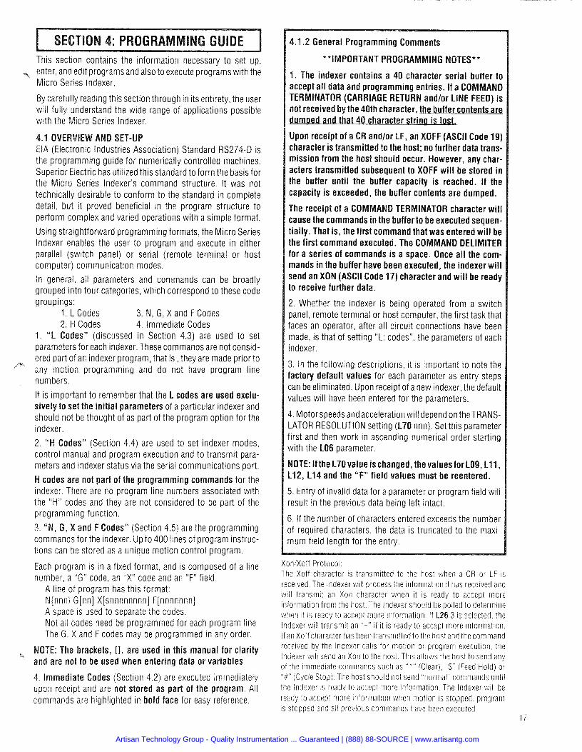
.1 .3 Programming Chart For lndexer Communications - "On The Fly" Commands
"On The Fly" commands can be sent to the indexer when it is "BUSY" (When motion or program execution is active or when previously transmitted commands are being processed)."On The Fly" commands allow the indexer to send status or position information to the host. The sequence for sending "On The Fly" commands is shown below. The host must send an "On The Fly" command, followed immediately by a carriage return (CR) and/or Line Feed (LF). If the command is not sent in this manner, it will not be treated as an "On The Fly" command. Instead, it will be placed in the buffer and executed when the indexer is no longer "BUSY".
1 HOST DEVICE SENDS ON THE FLY" COMMAND" I I
I HOST DEVICE WAITS FOR INDEXER TO SEND REQUESTED DATA I
The following commands can be sent the lndexer while it is "BUSY":
H I Scrlf Transmit Present Program Line Number H I 7crlf Transmit Present Absolute Position H I 8crlf Transmit Mode Status H I 9crlf Transmit Motion Status H2Ocrlf Transmit I10 Status
Any other commands sent to the lndexer will be executed when the lndexer is no longer "BUSY"
.l, Program Flow Chart For lndexer Communications
Artisan Technology Group - Quality Instrumentation ... Guaranteed | (888) 88-SOURCE | www.artisantg.com
.2 IMMEDIATE COMMANDS The "X command is executed immediately upon entry and is not stored as part of the program. I * CLEAR (ASCII Code 42) /
(s.
This command IMMEDIATELY halts all motor motion and program execution and will cause a loss of home position. The program line pointer is reset to the line number specified with the L41 parameter.
The RS232 input buffer is also cleared and the indexer trans- mits an XOFF and then an XON when a CLEAR command is used.
(ASCII CODE 36) 1 This command will immediately bring current motor motion to a controlled stop with deceleration determined by the L11 parameter (ACCELERATION/DECELERATION).
Motion can be continued without loss of position by using a NO1 CYCLE START command if the feedhold was applied during program execution. If a feedhold was applied during a H08 (return to electrical home) command, a subsequent H08 will continue the motion. A feedhold during a H I 0 (return to mechanical home) command requires a H I 0 to continue the motion. The line number cannot bealtered during afeedhold as the remaining move distance needs to be completed. A CLEAR ( * ) can be issued if it is not desired to complete the motion.
TTENTION CHARACTE
If <[nn] = 00, all indexers will be addressed; otherwise, the indexer with the value set by the L21 parameter that matches the <[nn] value will become the active indexer. The indexer will respond with " = XON" when the <[nn] value matches the value set with the L21 parameter and the indexer is ready for commands. If the indexer is not ready, the indexer responds with ":". If <00 is used, there is no indexer response.
This command halts program execution after the current program line is completed.
This command is used to stop programs executing with LO6 [2] [31 EXECUTION FORMAT settings.
H) BACKSPACE AND DELETE
The CONTROL H (&H) command will cause a backspace and delete one character on the current program line. The AH command is executed immediately upon entry and is not stored as part of the program.
The CONTROL X (A ) command will delete the program line that has been entered in the line buffer,
This command must be used prior to a COMMAND TERMINA- TOR.
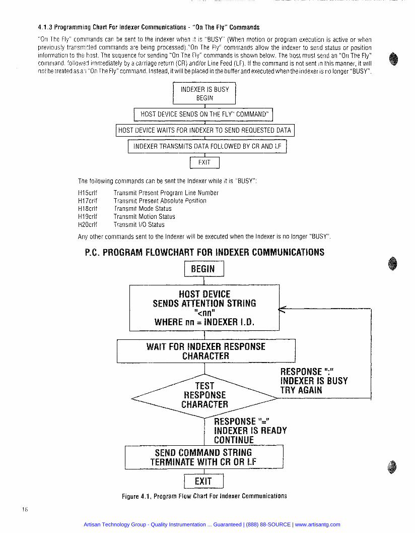
.3 L Codes: INDEXER PARAMETERS L codes are used to set parameters for each indexer. These parameters affect the entire operation of the indexer and cannot be changed during program execution; therefore, they should be programmed first. The Lcodes can be categorized into three areas of interest: motion, execution and serial communication parameters.
Motion parameters: L08, L09, L11, L12, L14, L17, L18, L19, L70
Execution parameters: L06, L07, L41, L44, L45, L48, L49
Communication parameters: L21, L22, L23, L25, L26
The L codes have been preset at the factory to default values; these are listed as "Factory Default" settings.
INDEXER PARAMETER FACTORY DEFAULT VALUES
Full Step 1/10 Step 11125 Step Translator Translator Translator
Artisan Technology Group - Quality Instrumentation ... Guaranteed | (888) 88-SOURCE | www.artisantg.com
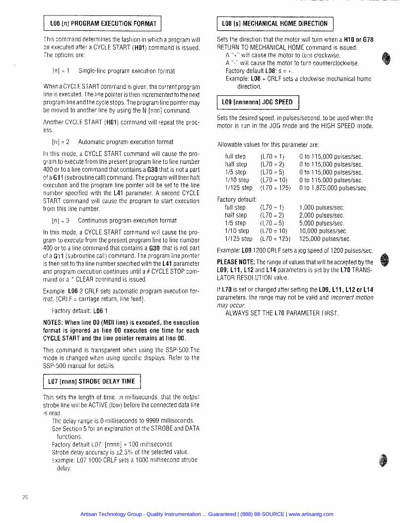
I LO8 [sl MECHANICAL HOME DIRECTION / This command determines the fashion in which a program will be executed after a CYCLE START (H01) command is issued. The options are:
[n] = 1 Single-line program execution format
When a CYCLE STARTcommand is given, the current program line is executed. The line pointer is then incremented to the next program line and the cycle stops. The program line pointer may be moved to another line by using the N [nnn] command.
Another CYCLE START (H01) command will repeat the proc- ess.
[n] = 2 Automatic program execution format
In this mode, a CYCLE START command will cause the pro- gram to execute from the present program line to line number 400 or to a line command that contains a G30 that is not a part of a GI1 (subroutine call) command. The program will then halt execution and the program line pointer will be set to the line number specified with the L41 parameter. A second CYCLE START command will cause the program to start execution from this line number.
[n] = 3 Continuous program execution format
In this mode, a CYCLE START command will cause the pro- gram to execute from the present program line to line number 400 or to a line command that contains a 630 that is not part
(subroutine call) command. The program line pointer is then set to the line number specified with the L41 parameter and program execution continues until a # CYCLE STOP com- mand or a * CLEAR command is issued.
Example: LO6 2 CRLF sets automatic program execution for- mat. [CRLF = carriage return, line feed].
Factory default: LO6 1
NOTES: When line 00 (MDI line) is executed, the execution format is ignored as line 00 executes one time for each CYCLE START and the line pointer remains at line 00.
This command is transparent when using the SSP-500.The mode is changed when using specific displays. Refer to the SSP-500 manual for details.
This sets the length of time, in milliseconds, that the output strobe line will be ACTIVE (low) before the connected data line is read.
The delay range is 0 milliseconds to 9999 milliseconds. See Section 5 for an explanation of the STROBE and DATA
functions. Factory default L07: [nnnn] = 100 milliseconds Strobe delay accuracy is i2.5•‹/0 of the selected value. Example: LO7 1000 CRLF sets a 1000 millisecond strobe
delay.
Sets the direction that the motor will turn when a H I 0 or 678 RETURN TO MECHANICAL HOME command is issued.
A "t" will cause the motor to turn clockwise. A "-" will cause the motor to turn counterclockwise. Factory default LO$: s = t. Example: LO8 t CRLF sets a clockwise mechanical home
direction.
LO9 [nnnnnnnl JOG SPEED
Sets the desired speed, in pulseslsecond, to be used when the motor is run in the JOG mode and the HIGH SPEED mode.
Allowable values for this parameter are:
full step (L70 = 1) 0 to 115,000 pulses/sec. half step (L70 = 2) 0 to 115,000 pulses/sec. 115 step (L70 = 5) 0 to 115,000 pulses/sec. 111 0 step (L70 = 10) 0 to 11 5,000 pulses/sec. 111 25 step (L70 = 125) 0 to 1,875,000 pulses/sec.
Factory default: full step (L70 = 1) 1,000 pulseslsec. half step (L70 = 2) 2,000 pulses/sec. 115 step (L70 = 5) 5,000 pulses/sec. 1/10 step (L70 = 10) 10,000 pulses/sec. 111 25 step (L70 = 125) 125,000 pulses/sec.
Example: LO9 1200 CRLF sets a jog speed of 1200 pulseslsec.
PLEASE NOTE: The range of values that will be accepted by the L09, L11, L12 and L14 parameters IS set by the L70 TRANS- LATOR RESOLUTION value.
If L70 is set or changed after setting the L09, L11, L12 or L14 parameters, the range may not be valid and incorrect motion may occur.
ALWAYS SET THE L70 PARAMETER FIRST.
Artisan Technology Group - Quality Instrumentation ... Guaranteed | (888) 88-SOURCE | www.artisantg.com
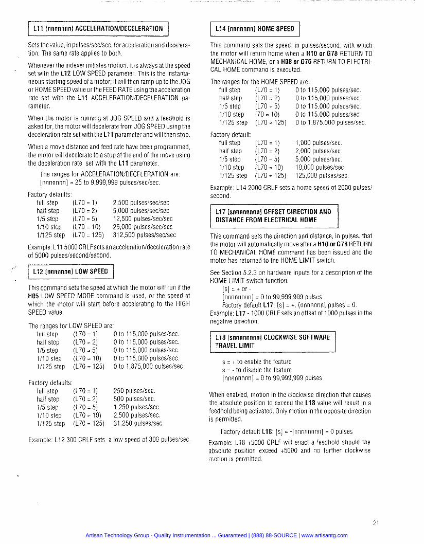
Sets the value, in pulses/sec/sec, for acceleration and decelera- tion. The same rate applies to both.
Whenever the indexer initiates motion, it is always at the speed set with the L12 LOW SPEED parameter. This is the instanta- neous starting speed of a motor; it will then ramp up to the JOG or HOME SPEED value orthe FEED RATE using the acceleration rate set with the L11 ACCELERATIONIDECELERATION pa- rameter.
When the motor is running at JOG SPEED and a feedhold is asked for, the motor will decelerate from JOG SPEED using the deceleration rate set with the L11 parameter and will then stop.
When a move distance and feed rate have been programmed, the motor will decelerate to a stop at the end of the move using the deceleration rate set with the L11 parameter.
The ranges for ACCELERATIONIDECELERATION are: [nnnnnnn] = 25 to 9,999,999 pulses/sec/sec.
Factory defaults: full step (L70 = 1) 2,500 pulses/sec/sec half step (L70 = 2) 5,000 pulses/sec/sec 115 step (L70 = 5) 12,500 pulseslseclsec 1110 step (L70 = 10) 25,000 pulses/sec/sec 111 25 step (L70 = 125) 31 2,500 pulses/sec/sec
Example: L11 5000 CRLFsets an accelerationldeceleration rate of 5000 pulses/second/second.
This command sets the speed at which the motor will run if the H05 LOW SPEED MODE command is used, or the speed at which the motor will start before accelerating to the HIGH SPEED value.
The ranges for LOW SPEED are: full step (L70 = 1) 0 to 115,000 pulseslsec. half step (L70 = 2) 0 to 115,000 pulseslsec. 115 step (L70 = 5) 0 to 11 5,000 pulseslsec. 1/10 step (L70 = 10) 0 to 115,000 pulseslsec. 11125 step (L70 = 125) 0 to 1,875,000 pulseslsec
Factory defaults: full step (L70 = 1) 250 pulseslsec. half step (L70 = 2) 500 pulseslsec. 115 step (L70 = 5) 1,250 pulseslsec. 1/10 step (L70 = 10) 2,500 pulseslsec. 11125 step (L70 = 125) 31,250 pulseslsec.
Example: L12 300 CRLF sets a low speed of 300 pulseslsec.
L14 [nnnnnnn] HOME SPEED
This command sets the speed, in pulseslsecond, with which the motor will return home when a H I 0 or 678 RETURN TO MECHANICAL HOME, or a H08 or 676 RETURN TO ELECTRI- CAL HOME command is executed.
The ranges for the HOME SPEED are: full step (L70 = 1) 0 to 11 5,000 pulseslsec. half step (L70 = 2) 0 to 115,000 pulseslsec. 115 step (L70 = 5) 0 to 115,000 pulseslsec. 111 0 step (70 = 10) 0 to 11 5,000 pulseslsec. 111 25 step (L70 = 125) 0 to 1,875,000 pulseslsec.
Factory default: full step (L70 = 1) 1,000 pulseslsec. half step (L70 = 2) 2,000 pulseslsec. 115 step (L70 = 5) 5,000 pulseslsec. 111 0 step (L70 = 10) 10,000 pulseslsec. 11125 step (L70 = 125) 125,000 pulseslsec
Exampie: L14 2000 CRLF sets a home speed of 2000 pulses1 second.
L17 [snnnnnnnnl OFFSET DIRECTION AND DISTANCE FROM ELECTRICAL HOME
This command sets the direction and distance, in pulses, that the motor will automatically move after a H I 0 or 678 RETURN TO MECHANICAL HOME command has been issued and the motor has returned to the HOME LIMIT switch.
See Section 5.2.3 on hardware inputs for a description of the HOME LIMIT switch function.
[s] = t o r - [nnnnnnnnj = 0 to 99,999,999 pulses. Factory default L17: [s] = t: [nnnnnnn] pulses = 0.
Example: L17 - 1000 CRLF sets an offset of 1000 pulses in the negative direction.
L18 [snnnnnnnnl CLOCKWISE SOFTWARE TRAVEL LIMIT
s = t to enable the feature s = - to disable the feature [nnnnnnnn] = 0 to 99,999,999 pulses
When enabled, motion in the clockwise direction that causes the absolute position to exceed the L18 value will result in a feedhold being activated. Only motion in the opposite direction is permitted.
Factory default L18: [s] = -[nnnnnnnn] = 0 pulses
Example: L18 t5000 CRLF will enact a feedhold should the absolute position exceed t5000 and no further clockwise motion is permitted.
Artisan Technology Group - Quality Instrumentation ... Guaranteed | (888) 88-SOURCE | www.artisantg.com
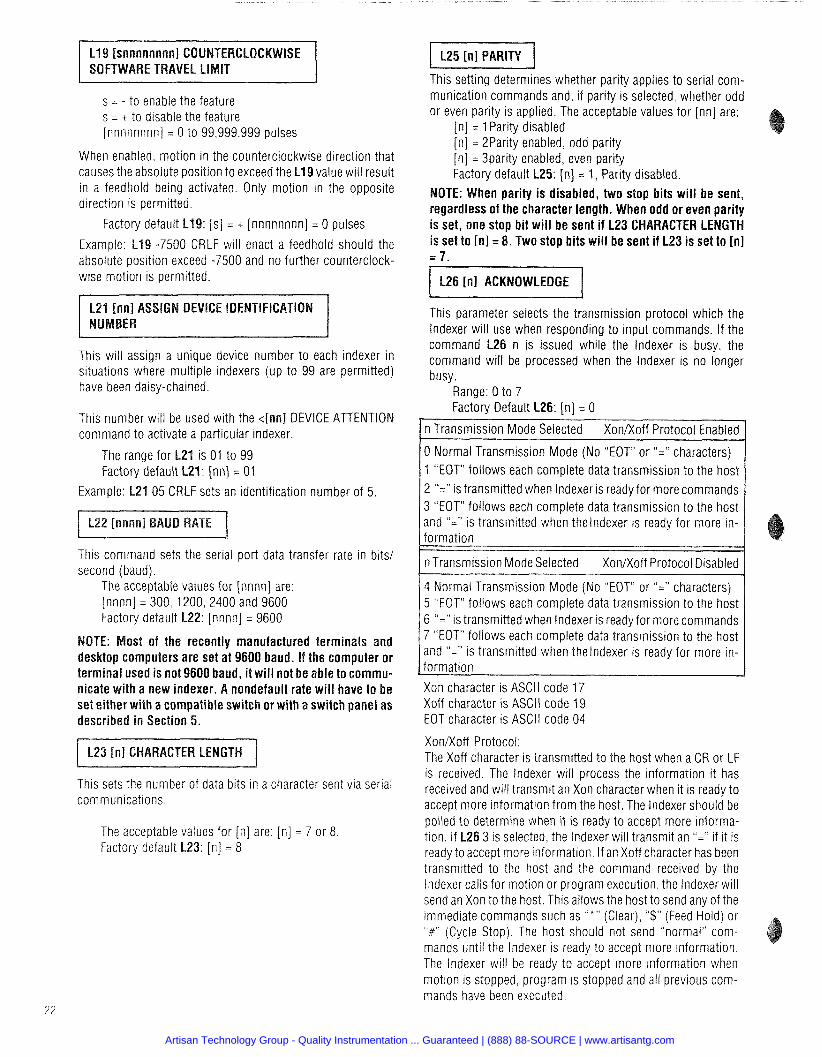
s = - to enable the feature s = t to disable the feature [nnnnnnnn] = 0 to 99,999,999 pulses
When enabled, motion in the counterclockwise direction that causes the absolute position to exceed the L19 value will result in a feedhold being activated. Only motion in the opposite direction is permitted.
: [s] = t [nnnnnnnn] = 0 pulses
Example: L19 -7500 CRLF will enact a feedhold should the absolute position exceed -7500 and no further counterclock- wise motion is permitted.
This will assign a unique device number to each indexer in situations where multiple indexers (up to 99 are permitted) have been daisy-chained.
This number will be used with the 4 n n l DEVICE ATTENTION command to activate a particular indexer.
The range for L21 is 01 to 99 Factory default L21: inn] = 01
Example: L21 05 CRLF sets an identification number of 5.
This command sets the serial port data transfer rate in bits1 second (baud).
The acceptable values for [nnnn] are: [nnnn] = 300, 1200,2400 and 9600 Factory default L22: [nnnn] = 9600
ost of the recently manufactured terminals and desktop computers are set at 9600 baud. If the computer or terminal used is not 9600 b d, it will not be able to commu- nicate with a new indexer. nondefault rate will have to be set either with a compatible switch or with a switch panel as described in Section 5.
I L23 [nl CHARACTER LE
This sets the number of data bits in a character sent via serial communications.
The acceptable values for [n] are: [n] = 7 or 8 Factory default L23: [n ] = 8
This setting determines whether parity applies to serial com- munication commands and, if parity is selected, whether odd or even parity is applied. The acceptable values for [nn] are:
[n] = 1 Parity disabled [n] = 2Parity enabled, odd parity [n] = 3parity enabled, even parity Factory default L25: [n] = 1, Parity disabled.
OTE: When parity is disabled, two stop bits will be sent, regardless of the character length. When odd or even parity is set, one stop bit will be sent if L23 CHARACTER LENGTH is set to [nl = 8. Two stop bits will be sent if L23 is set to [nl = 7.
This parameter selects the transmission protocol which the lndexer will use when responding to input commands. If the command L26 n is issued while the lndexer is busy, the command will be processed when the lndexer is no longer busy.
Range: 0 to 7 Factory Default L26: [n] = 0
n Transmission Mode Selected XonRoff Protocol Enabled
0 Normal Transmission Mode (No "EOT" or "=" characters) 1 "EOT" follows each complete data transmission to the host 2 "=" is transmitted when Indexer is ready for more commands 3 "EOT" follows each complete data transmission to the host and "=" is transmitted when thelndexer is ready for more in- formation
n Transmission Mode Selected XonRoff Protocol Disabled
4 Normal Transmission Mode (No "EOT" or "=" characters) 5 "EOT" follows each complete data transmission to the host 6 "=" is transmitted when lndexer is ready for more commands 7 "EOT" follows each complete data transmission to the host and "=" is transmitted when thelndexer is ready for more in- formation
Xon character is ASCll code 17 Xoff character is ASCll code 19 EOT character is ASCll code 04
XonRoff Protocol: The Xoff character is transmitted to the host when a CR or LF is received. The lndexer will process the information it has received and will transmit an Xon character when it is ready to accept more information from the host. The lndexer should be polled to determine when it is ready to accept more informa- tion. If L26 3 is selected, the lndexer will transmit an "=" if it is ready to accept more information. If an Xoff character has been transmitted to the host and the command received by the lndexer calls for motion or program execution, the lndexer will send an Xon to the host. This allows the host to send any of the immediate commands such as " * " (Clear), "$" (Feed Hold) or "f" (Cycle Stop). The host should not send "normal" com- mands until the lndexer is ready to accept more information. The lndexer will be ready to accept more information when motion is stopped, program is stopped and all previous com- mands have been executed.
Artisan Technology Group - Quality Instrumentation ... Guaranteed | (888) 88-SOURCE | www.artisantg.com
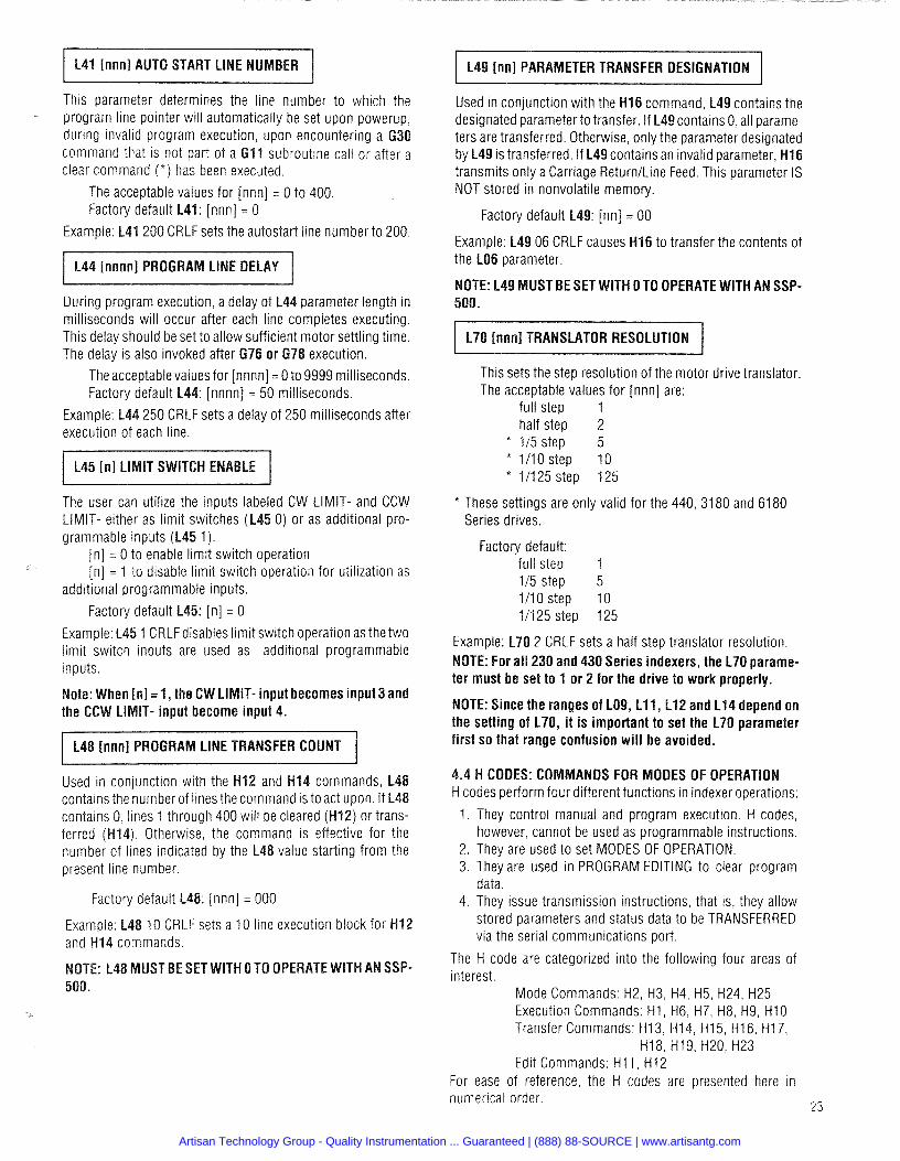
This parameter determines the line number to which the - program line pointer will automatically be set upon powerup,
during invalid program execution, upon encountering a G30 command that is not part of a G I1 subroutine call or after a clear command ( * ) has been executed.
The acceptable values for [nnn] = 0 to 400. Factory default L41: [nnn] = 0
1 200 CRLF sets the autostart line number to 200.
During program execution, a delay of L44 parameter length in milliseconds will occur after each line completes executing. This delay should be set to allow sufficient motor settling time. The delay is also invoked after G76 or 67
sfor [nnnn] = 0 to 9999 milliseconds. [nnnn] = 50 milliseconds.
ets a delay of 250 milliseconds after execution of each line.
IT SWITCH ENABLE I The user can utilize the inputs labeled CW LIMIT- and CCW LIMIT- either as limit switches (L45 0) or as additional pro- grammable inputs (L45 1).
[n] = 0 to enable limit switch operation [n] = 1 to disable limit switch operation for utilization as
additional programmable inputs.
Factory default L45: [n] = 0
Example: L45 1 CRLFdisables limit switch operation as the two limit switch inputs are used as additional programmable inputs.
ote: When [n] = 1, the CW LIMIT- input becomes input 3 and IT- input become input
I L48 [nnn] PROGRA LINE TRANSFER COUNT / Used in conjunction with the H12 and H I 4 commands, L48 contains the number of lines the command is to act upon. If L48 contains 0, lines 1 through 400 will be cleared (H12) or trans-
) . Otherwise, the command is effective for the number of lines indicated by the L48 value starting from the present line number.
Factory default L48: [nnn] = 000
Example: L48 10 CRLF sets a 10 line execution block for H12
UST BE SET WlTH 0 TO OPER 500.
Used in conjunction with the H I 6 command, L49 contains the designated parameter to transfer. If L49contains 0, all parame- ters are transferred. Otherwise, only the parameter designated by L49 is transferred. If L49 contains an invalid parameter, H I 6 transmits only a Carriage ReturnILine Feed. This parameter IS NOT stored in nonvolatile memory.
Factory default L49: [nn] = 00
Example: L49 06 CRLF causes H I 6 to transfer the contents of the LO6 parameter.
UST BE SET WlTH 0 TO OPERATE WlTH AN SSP- 500.
L70 [nnnl TRANSLATOR RESOLUTION
This sets the step resolution of the motor drive translator The acceptable values for [nnn] are:
full step 1 half step 2
* 115 step 5 * 1/10 step 10 * 11125step 125
* These settings are only valid for the 440, 3180 and 6180 Series drives.
Factory default: full step 1 115 step 5 1/10 step 10 111 25 step 125
Example: L70 2 CRLF sets a half step tsanslator resolution. OTE: For all 230 and 430 Series indexers, the L70 parame-
ter must be set to 1 or 2 for the drive to work properly.
OTE: Since the ranges of L09, L l l , L12 and L14 depend on the setting of L70, it is important to set the L70 parameter first so that range confusion will be avoided.
.4 H CODES: COMMANDS FOR MODES OF OPERATION H codes perform four different functions in indexer operations:
1. They control manual and program execution. H codes, however, cannot be used as programmable instructions.
2. They are used to set MODES OF OPERATION, 3. They are used in PROGRAM EDITING to clear program
data. 4. They issue transmission instructions, that is, they allow
stored parameters and status data to be TRANSFERRED via the serial communications port.
The H code are categorized into the following four areas of interest.
Mode Commands: H2, H3, H4, H5, H24, H25 Execution Commands: H I , H6, H7, H8, H9, H I 0 Transfer Commands: H13, H14, H15, H16, H17,
H18, H19, H20, H23 Edit Commands: H1 1, H I 2
For ease of reference, the H codes are presented here in numerical order.
23
Artisan Technology Group - Quality Instrumentation ... Guaranteed | (888) 88-SOURCE | www.artisantg.com
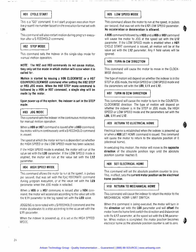
I HQ1 CYCLE START I H05 LOW SPEED MODE
This is a "GO" command. It will start program execution from the present line number based on the execution format set with
This command will also restart motion during program execu- tion after a $ FEEDHOLD command.
This command sets the indexer in the single-step mode for manual motion operation.
OTE: The HQ2 and H03 commands do not cause motion, they only set the mode in which motion will occur when it is called for.
otion is started by issuing a H06 CLOCKWISE or a HQ7 COUNTERCLOCKWISE command after setting the H02 STEP or H03 JOG mode. When the H02 STEP mode command is followed by a H06 or H07 command, a single step will be made by the motor.
Upon power up of the system, the indexer is set in the STEP
I H03 JOG MODE I This command sets the indexer in the continuous motion mode for manual motion operation.
When a H06 or H07 command is issued after a H03 command, the motor will turn continuously until a $ FEEDHOLD command is issued.
The speed at which the motor will turn is dependent on whether the HlGH SPEED or the LOW SPEED mode has been selected.
If the HlGH SPEED mode is enabled, the motor will run at the value set with the LO9 parameter. If the LOW SPEED mode is enabled. the motor will run at the value set with the L12 parameter.
This command allows the motor to run at the speed, in pulses per second, that was set with the F[x] FEEDRATE command during program execution, or at the value set with the L parameter when the JOG mode is selected.
or a HQ7 command is issued after a HQ4 com- mand, the motor will accelerate according to the value set with the L11 parameter to the jog speed set with the LO9 value.
JOGGING is terminated with a $ FEEDHOLD command and the motor decelerates to a stop according to the value set with the L11 parameter.
When the indexer is powered up, it is set in the HlGH SPEED MODE.
This command allows the motor to run at the speed, in pulses per second, that was set with the L12 LOW SPEED parameter.
o acceleration or deceleration is allowed.
A H05 command followed by a H03 and a H06 or H07 command will cause the motor to JOG at the speed set with the L12 parameter. If the LOW SPEED mode is enabled when a H01 CYCLE START command is issued, all motion will be at the value set with the L12 parameter. Any F field values will be ignored.
H06 TURN IN CW DIRECTION
This command will cause the motor to move in the CLOCK- WISE direction.
The type of motion will depend on whether the indexer is in the STEP or JOG mode, the HlGH SPEED or LOW SPEED mode and the parameters set with the L09, L11 and L12.
I H07 TURN IN CCW DIRECTION I This command will cause the motor to turn in the COUNTER- CLOCKWISE direction. The type of motion will depend on whether the indexer is in the STEP or JOG mode, the HlGH SPEED or LOW SPEED mode and the parameters set with the LQ9, L11 and L12.
Electrical home is established when the indexer is powered up or when a H09 SET HOME command is issued. This command will cause the motor to return to the absolute position of 0 (electrical home).
In executing this motion, the motor will move in the opposite direction of the absolute position sign until the absolute position counter reaches 0.
H09 SET ELECTRICAL HOME
This command will set the absolute position counter to zero. This, in effect, sets the current motor position as the electrical home position.
HlO RETURN TO MECHANICAL HOME
This command will cause the indexer to return the motor to the MECHANICAL HOME LIMIT SWITCH.
When this command is being executed, the motor will turn in the direction set with the LO8 parameter and will offset the motor from the home limit switch the direction and distance set with the L17 parameter, at the speed set with the L14 parame- ter. When motion is completed, the motor position becomes electrical home as the absolute position counter is set to zero.
Artisan Technology Group - Quality Instrumentation ... Guaranteed | (888) 88-SOURCE | www.artisantg.com
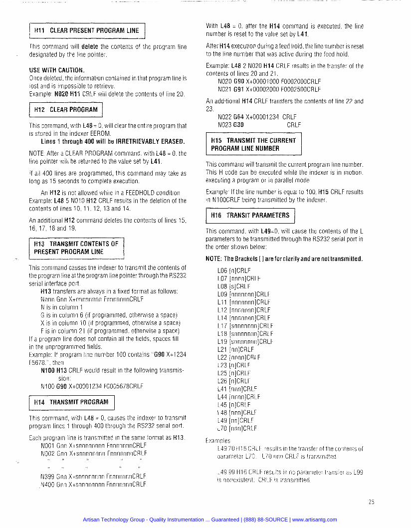
This command will delete the contents of the program line designated by the line pointer.
rmation contained in that program line is
lete the contents of line 20.
This command, with L48 = 0, will clear the entire program that is stored in the indexer EEROM.
Lines 1 through 400 will be IRRETRIEVABLY ERASED.
NOTE: After a CLEAR PROGRAM command, with L48 = 0, the line pointer will be returned to the value set by L41.
If all 400 lines are programmed, this command may take as long as 15 seconds to complete execution.
12 is not allowed while in a FEEDHOLD condition Example: L48 5 NO10 H12 CRLF results in the deletion of the contents of lines 10, 11, 12, 13 and 14.
An additional H12 command deletes the contents of lines 15, 16,17,18 and 19.
This command causes the indexer to transmit the contents of the program line at the program line pointerthrough the RS232 serial interface port.
H13 transfers are always in a fixed format as follows: Nnnn Gnn Xtnnnnnnnn FnnnnnnnCRLF N is in column 1 G is in column 6 (if programmed, otherwise a space) X is in column 10 (if programmed, otherwise a space) F is in column 21 (if programmed, otherwise a space)
If a program line does not contain all the fields, spaces fill in the unprogrammed fields. Example: If program line number 100 contains "G90 Xt1234 F5678,". then
100 H13 CRLF would result in the following transmis- sion:
N l 00 G90 Xt00001234 F0005678CRLF
This command, with L48 = 0, causes the indexer to transmit program lines 1 through 400 through the RS232 serial port.
Each program line is transmitted in the same format as H13. NO01 Gnn Xtsnnnnnnnn FnnnnnnnCRLF NO02 Gnn Xtsnnnnnnnn FnnnnnnnCRLF
& t ! t
N399 Gnn Xtsnnnnnnnn FnnnnnnnCRLF N400 Gnn Xtsnnnnnnnn FnnnnnnnCRLF
With L48 = 0, after the H14 command is executed, the line number is reset to the value set by L41.
After H14 execution during afeed hold. the line number is reset to the line number that was active during the feed hold.
Example: L48 2 NO20 H14 CRLF results in the transfer of the contents of lines 20 and 21.
NO20 G90 Xt00001000 F0002000CRLF NO21 G91 Xt00002000 F0002500CRLF
An additional H14 CRLF transfers the contents of line 22 and 23.
NO22 G64 Xt00001234 CRLF NO23 630 CRLF
H15 TRANSMIT THE CURRENT PROGRAM LINE NUMBER
This command will transmit the current program line number. This H code can be executed while the indexer is in motion, executing a program or in parallel mode.
Example: If the line number is equal to 100, H15 CRLF results in NIOOCRLF being transmitted by the indexer.
/ H I 6 TRANSIT PARAMETERS I This command, with L49=0, will cause the contents of the L parameters to be transmitted through the RS232 serial port in the order shown below:
Examples 149 70 H16 CRLF results In the transfer of the contents of parameter L70: L70 nnn CRLF is transmitted
149 99 H16 CRLF results In no parameter transfer as 199 is nonexistent: CRLF is transm~tted.
Artisan Technology Group - Quality Instrumentation ... Guaranteed | (888) 88-SOURCE | www.artisantg.com
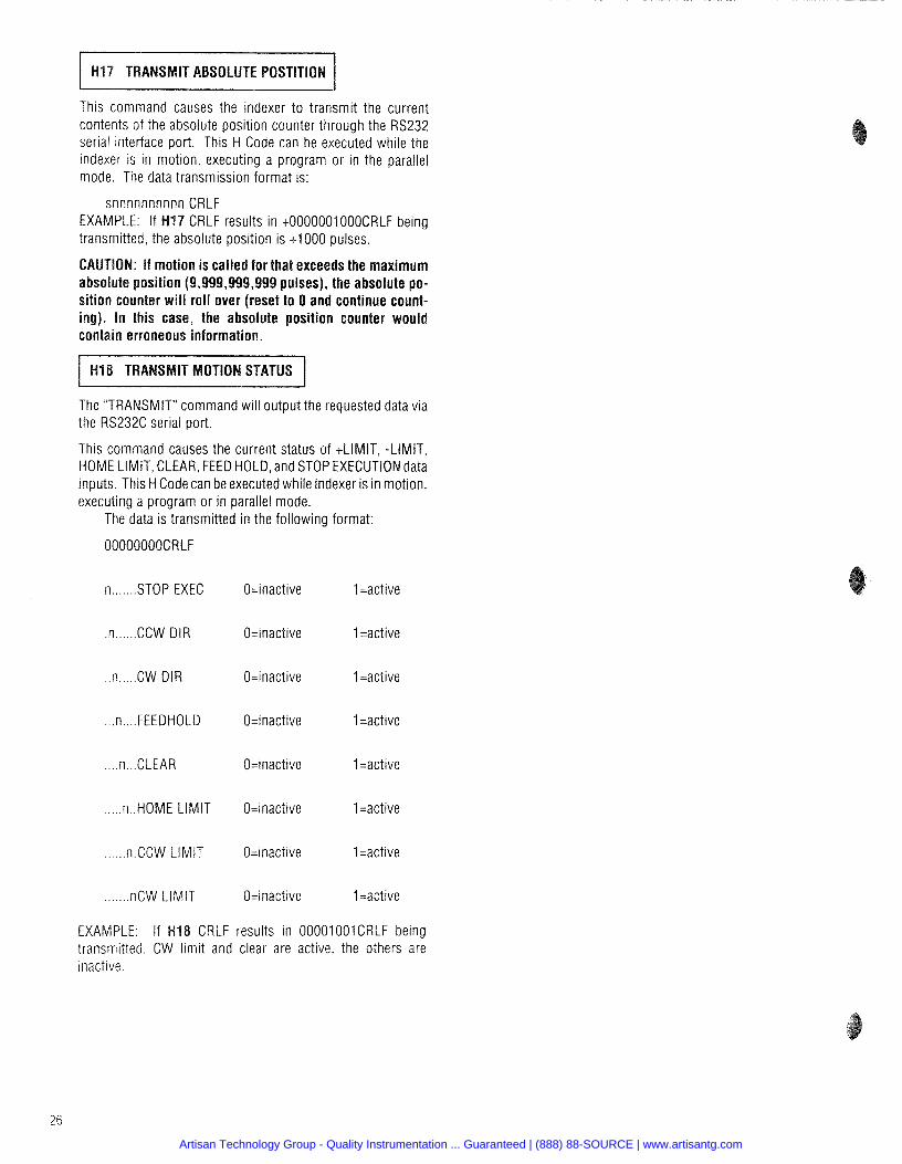
This command causes the indexer to transmit the current contents of the absolute position counter through the RS232 serial interface port. This H Code can be executed while the indexer is in motion, executing a program or in the parallel mode. The data transmission format is:
snnnnnnnnnn CRLF EXAMPLE: If H I 7 CRLF results in t0000001000CRLF being transmitted, the absolute position is t1000 pulses.
: If motion is called for that exceeds the maximum absolute position (9,999,999,999 pulses), the absolute po- sition counter will roll over (reset to 0 and continue count- ing). In this case, the absolute position counter would contain erroneous information.
TRANSMIT MOTlO
The "TRANSMIT" command will output the requested data via the RS232C serial port.
This command causes the current status of tLIMIT, -LIMIT, HOME LIMIT, CLEAR, FEED HOLD, and STOP EXECUTION data inputs. This H Code can be executed while indexer is in motion, executing a program or in parallel mode.
The data is transmitted in the following format:
OOOOOOOOCRLF
n ....... STOP EXEC O=inactive 1 =active
.n ...... CCW DIR O=inactive 1 =active
.n.....CW DIR O=inactive 1 =active
.n,.HOME LIMIT O=inactive 1 =active
...... n.CCW LIMIT O=inactive 1 =active
.nCW LIMIT O=inactive 1 =active
EXAMPLE: If H I 8 CRLF results in OOOO1OOICRLF being transmitted. CW limit and clear are active, the others are inactive
Artisan Technology Group - Quality Instrumentation ... Guaranteed | (888) 88-SOURCE | www.artisantg.com
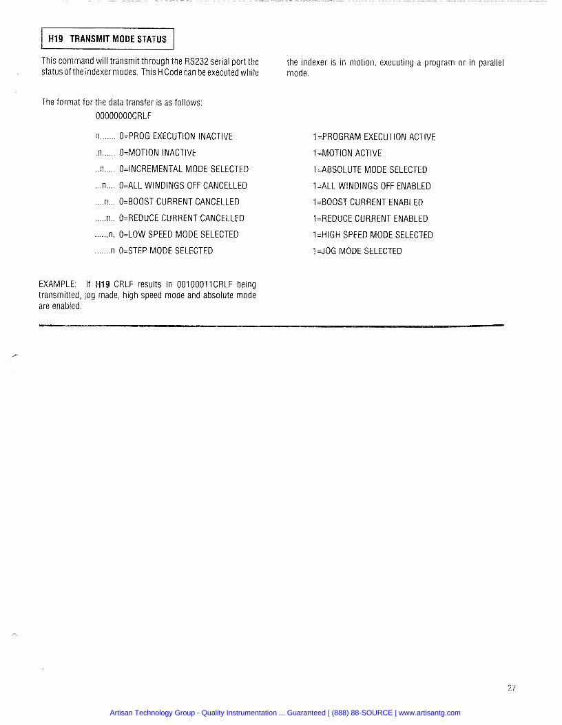
IT MODE STATUS I This command will transmit through the RS232 serial port the the indexer is in motion, executing a program or in parallel status of the indexer modes. This H Code can be executed while mode.
The format for the data transfer is as follows:
OOOOOOOOCRLF
n ....... O=PROG EXECUTION INACTIVE
.n ...... O=MOTION INACTIVE
..n ..... O=INCREMENTAL MODE SELECTED
... n .... O=ALL WINDINGS OFF CANCELLED
.... n... O=BOOST CURRENT CANCELLED
..... n.. O=REDUCE CURRENT CANCELLED
...... n. O=LOW SPEED MODE SELECTED
....... n O=STEP MODE SELECTED
1 =PROGRAM EXECUTION ACTIVE
1 =MOTION ACTIVE
1 =ABSOLUTE MODE SELECTED
1=ALL WINDINGS OFF ENABLED
1=BOOST CURRENT ENABLED
1=REDUCE CURRENT ENABLED
1 =HIGH SPEED MODE SELECTED
1 =JOG MODE SELECTED
EXAMPLE: If H I 9 CRLF results in 00100011CRLF being transmitted, jog made, high speed mode and absolute mode are enabled.
Artisan Technology Group - Quality Instrumentation ... Guaranteed | (888) 88-SOURCE | www.artisantg.com
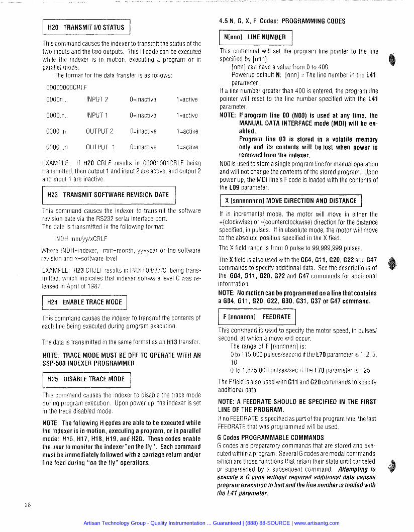
This command causes the indexer to transmit the status of the two inputs and the two outputs. This H code can be executed while the indexer is in motion, executing a program or in parallel mode.
The format for the data transfer is as follows:
OOOOOOOOCRLF
0000n . . . INPUT 2 O=inactive 1 =active
OOOO.n.. INPUT 1 O=inactive 1 =active
0000..n. OUTPUT 2 O=inactive 1 =active
0000 ... n OUTPUT 1 O=inactive 1 =active
EXAMPLE: If H20 CRLF results in 00001001CRLF being transmitted, then output 1 and input 2 are active, and output 2 and input 1 are inactive.
1 H23 TRANSMIT SOFTWARE REVISION DATE 1 This command causes the indexer to transmit the software revision date via the RS232 serial interface port. The date is transmitted in the following format:
INDH mmiyylxCRLF
Where INDH=indexer. mrn=month, yy=year or the software revision and x=software level
EXAMPLE: H23 CRJLF results in INDH 04/87/C being trans- mitted, which indicates that indexer software level C was re- leased in April of 1987.
This command causes the indexer to transmit the contents of each line being executed during program execution.
The data is transmitted in the same format as an H I 3 transfer.
ODE MUST BE OFF TO OPER SSP-500 INDEXER PROGRAMMER
This command causes the indexer to disable the trace mode during program execution. Upon power up. the indexer is set in the trace disabled mode.
: The following H codes are able to be executed while er is i n motion, executing a program, or in parallel 15, H17, H18, H19, and H20. These codes enable
the user to monitor the indexerson the fly1'. Each command must be immediately followed with a carriage return and/or line feed during "on the fly" operations.
.5 N, 6 , X, F Codes: PROGRAMMING CODES
This command will set the program line pointer to the line specified by [nnn].
[nnn] can have a value from 0 to 400. Powerup default N: [nnn] = The line number in the L parameter.
If a line number greater than 400 is entered, the program line pointer will reset to the line number specified with the L41 parameter.
rogram line 00 (NOO) is used at any time, the NUAL DATA INTERFACE mode (MDI) w i l l be en- ed.
rogram line 00 is stored i n a volatile memory only and its contents wi l l be lost when power is removed from the indexer.
NO0 is used to store a single program line for manual operation and will not change the contents of the stored program. Upon power up, the MDI line's F code is loaded with the contents of the LO9 parameter.
I X [snnnnnnnnl MOVE DIRECTION AND DISTANCE I If in incremental mode, the motor will move in either the +(clockwise) or -(counterclockwise) direction for the distance specified, in pulses. If in absolute mode, the motor will move to the absolute position specified in the X field.
The X field range is from 0 pulse to 99,999,999 pulses.
eld IS also used wlth the nds to spec~fy add~t~onal
the 604, 611, 620, 622 and 647 commands for add~tlonal mformatlon
OTE: No motion can be programmed on a line that contains a 604, 611, 620, 622, 630, 631,637 or 647 command.
/ F [nnnnnnnl FEEDRATE I This command is used to specify the motor speed, in pulses1 second, at which a move will occur.
The range of F [nnnnnnn] is: 0 to 11 5,000 pulses/second if the L70 parameter is 1 ,2 .5 . 10 0 to 1,875.000 pulsesisec if the L70 parameter is 125
The F field is also used with G I1 and G20 commands to specify additional data.
FEEDRATE SHOULD BE SPECIFIED IN THE FIRST LINE OF THE PROGRAM. If no FEEDRATE is specified as part of the program line, the last FEEDRATE that was programmed will be used.
G Codes PROGRAMMABLE COMMANDS G codes are preparatory commands that are stored and exe- cuted within a program. Several G codesare modal commands which are those functions that retain their state until canceled or superseded by a subsequent command. Attempting to execute a G code without required additional data causes program execution to halt and the line number is loaded with the L41 parameter.
Artisan Technology Group - Quality Instrumentation ... Guaranteed | (888) 88-SOURCE | www.artisantg.com
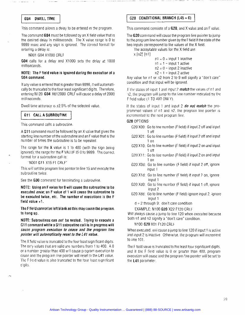
1 620 CONDITIONAL BRANCH (L45 = 0) 1 This command allows a delay to be entered in the program.
must be followed by an X field value that is the desired delay in milliseconds. The X value range is 0 to 9999 msec and any sign is ignored. The correct format for entering a delay is:
NO01 GO4 X1000 CRLF
calls for a delay and XI000 sets the delay at 1000 milliseconds.
E: The F field value is ignored during the execution of a command.
If any value is entered that is greaterthan 9999, it will automati- cally be truncated to the four least significant digits. Therefore, entering N120 GO4 X612000 CRLF will cause a delay of 2000 milliseconds.
Dwell time accuracy is Q . 5 % of the selected value.
This command calls a subroutine.
A GI1 command must be followed by an X value that gives the starting line number of the subroutine and an Fvalue that is the number of times the subroutine is to be repeated.
The range for the value is 1 to 400 (with the sign being ignored); the range for the VALUE IS 0 to 9999. The correct format for a subroutine call is:
"NO01 GI1 X15 F1 CRLF" This will set the program line pointer to line 15 and execute the subroutine twice.
command for terminating a subroutine
NOTE: Using an F value for 0 will cause the subroutine to be executed once; an F value of 1 will cause the subroutine to be executed twice, etc. The number of executions is the F
The Ffield cannot be left blankas this may cause the program
broutines can not be nested. T mand while a Gll subroutine call
cause program execution to cease and fhe program line pointer will automatically reset to the L41 value.
The X field value is truncated to the four least significant digits. The only values that are valid are numbers from 1 to 400. A 0 or a number greater than 400 will cause program execution to cease and the program line pointer will reset to the L41 value. The F field value is also truncated to the four least significant digits.
This command consists of a 620, and X value and an F value.
The 620 command will cause the program line pointer to jump to the program line number given by the Ffield if the state of the two inputs correspoond to the values of the X field.
The acceptable values for the X field are: x In21 [n11
n l = 0 = input 1 inactive n l = 1 = input 1 active n2 = 0 = input 2 inactive n2 = 1 = input 2 active
Any value for n l or n2 from 2 to 9 will signify a "don't care" condition and that input will be ignored.
If the states of input 1 and input 2 match the values of n l and n2, the program will jump to the line number indicated by the F field value (1 TO 400 ONLY).
If the states of input 1 and input 2 do not match the pro- grammed values of n l and n2, the program line pointer is incrernented to the next program line.
20 OPTIONS: G20 XOO: Go to line number (F field) if input 2 off and input
1 off G20 XO1: Go to line number (F field) if input 2 off and input
1 on G20 X10: Go to line number (F field) if input 2 on and input
1 off G20 XI 1: Go to line number (F field) if input 2 on and input
1 on G20 XOd: Go to line number (F field) if input 2 off, ignore
input 1 G20 Xld: Go to line number (F field) if input 2 on, ignore
input 1 620 XdO: Go to line number (F field) if input 1 off, ignore
input 2 G20 Xdd: Go to line number (F field) ignore input 2, ignore
input 1 d = 2 through 9: don't care condition EXAMPLE: N100 620 X22 F120 CRLF
Will always cause a jump to line 120 when executed because both n l and n2 signify a "don't care" condition.
N l00 G20 X01 F120 CRLF
When executed, will cause a jump to line 120 if input 1 is active and input 2 is inactive. Otherwise, the program will increment to line 101.
The F field value is truncated to the least four significant digits, and if the F field value is 0 or greater than 400, program execution will cease and the program line pointer will be set to the L41 parameter.
Artisan Technology Group - Quality Instrumentation ... Guaranteed | (888) 88-SOURCE | www.artisantg.com
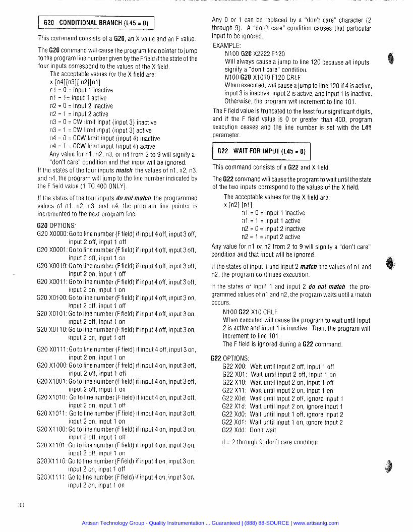
620 CONDITIONAL BRANCH (L45 = 0)
This command consists of a 620, an X value and an F value.
The 620 command will cause the program line pointer to jump to the program line number given by the Ffield if the state of the four inputs correspond to the values of the X field.
The acceptable values for the X field are: x [n41[n31[ n 2 W I n l = 0 = input 1 inactive n1 = l = input 1 active n2 = 0 = input 2 inactive n2 = 1 = input 2 active n3 = 0 = CW limit input (input 3) inactive n3 = 1 = CW limit input (input 3) active n4 = 0 = CCW limit input (input 4) inactive n4 = 1 = CCW limit input (input 4) active Any value for n l , n2, n3, or n4 from 2 to 9 will signify a "don't care" condition and that input will be ignored.
If the states of the four inputs match the values of n l , n2, n3, and n4, the program will jump to the line number indicated by the F field value (1 TO 400 ONLY).
If the states of the four inputs do not match the programmed values of n l , n2, n3. and n4, the program line pointer is incremented to the next program line.
620 OPTIONS: G20 X0000: Go to line number (F field) if input 4 off, input 3 off,
input 2 off, input 1 off G20 X0001 :Go to line number (F field) if input 4 off, input 3 off,
input 2 off, input 1 on G20 XOOIO: Go to line number (Ffield) if input 4 off, input 3 off,
input 2 on, input 1 off G20 XOO11 :Go to line number (F field) if input 4 off, input 3 off,
input 2 on, input 1 on G20 X0100: Go to line number (F field) if input 4 off, input 3 on,
input 2 off, input 1 off G20 X0101 :Go to line number (F field) if input 4 off, input 3 on,
input 2 off, input 1 on G20 XO110: Go to line number (Ffield) if input 4 off, input 3 on,
input 2 on, input 1 off
G20 X0111: Go to line number (Ffield) if input 4 off, input 3 on, input 2 on, input 1 on
G20 X1000: Go to line number (Ffield) if input 4 on, input 3 off, input 2 off, input 1 off
G20 X I 001 : Go to line number (F field) if input 4 on, input 3 off, input 2 off, input 1 on
G20 X1010: Go to line number (Ffield) if input 4 on, input 3 off, input 2 on, input 1 off
G20 XI01 1: Go to line number (Ffield) if input 4 on, input 3 off, input 2 on, input 1 on
G20 X1 100: Go to line number (Ffield) if input 4 on, input 3 on, input 2 off, input 1 off
G20 X1 101: Go to line number (Ffield) if input 4 on, input 3 on, input 2 off, input 1 on
G20 X1 11 0: Go to line number (Ffield) if input 4 on, input 3 on, input 2 on, input 1 off
G20 X I 11 1 : Go to line number (F field) if input 4 on, input 3 on, input 2 on, input 1 on
Any 0 or 1 can be replaced by a "don't care" character (2 through 9). A "don't care" condition causes that particular input to be ignored. EXAMPLE:
N l 00 620 X2222 F120 Will always cause a jump to line 120 because all inputs signify a "don't care" condition. N l00 620 X I 01 0 F120 CRLF When executed, will cause a jump to line 120 if 4 is active, input 3 is inactive, input 2 is active, and input 1 is inactive. Otherwise, the program will increment to line 101.
The F field value is truncated to the least four significant digits, and if the F field value is 0 or greater than 400, program execution ceases and the line number is set with the L41 parameter.
622 WAIT FOR INPUT (L45 = 0)
This command consists of a 622 and X field
The 622command will cause the program to wait until the state of the two inputs correspond to the values of the X field.
The acceptable values for the X field are: x in21 In1 I
n l = 0 = input 1 inactive n1 = 1 = input 1 active n2 = 0 = input 2 inactive n2 = 1 = input 2 active
Any value for n l or n2 from 2 to 9 will signify a "don't care" condition and that input will be ignored.
If the states of input 1 and input 2 match the values of n l and n2, the program continues execution.
If the states of input 1 and input 2 do not match the pro- grammed values of n l and n2, the program waits until a match occurs.
N100 622 X I0 CRLF When executed will cause the program to wait until input 2 is active and input 1 is inactive. Then, the program will increment to line 101. The F field is ignored during a 622 command.
22 OPTIONS: G22 XOO: Wait until input 2 off, input 1 off 622 XOl: Wait until input 2 off, input 1 on G22 X10: Wait until input 2 on, input 1 off G22 X I 1: Wait until input 2 on, input 1 on G22 XOd: Wait until input 2 off, ignore input 1 G22 Xld: Wait until input 2 on, ignore input 1 G22 XdO: Wait until input 1 off, ignore input 2 G22 Xdl: Wait until input 1 on, ignore input 2 G22 Xdd: Don't wait
d = 2 through 9: don't care condition
Artisan Technology Group - Quality Instrumentation ... Guaranteed | (888) 88-SOURCE | www.artisantg.com
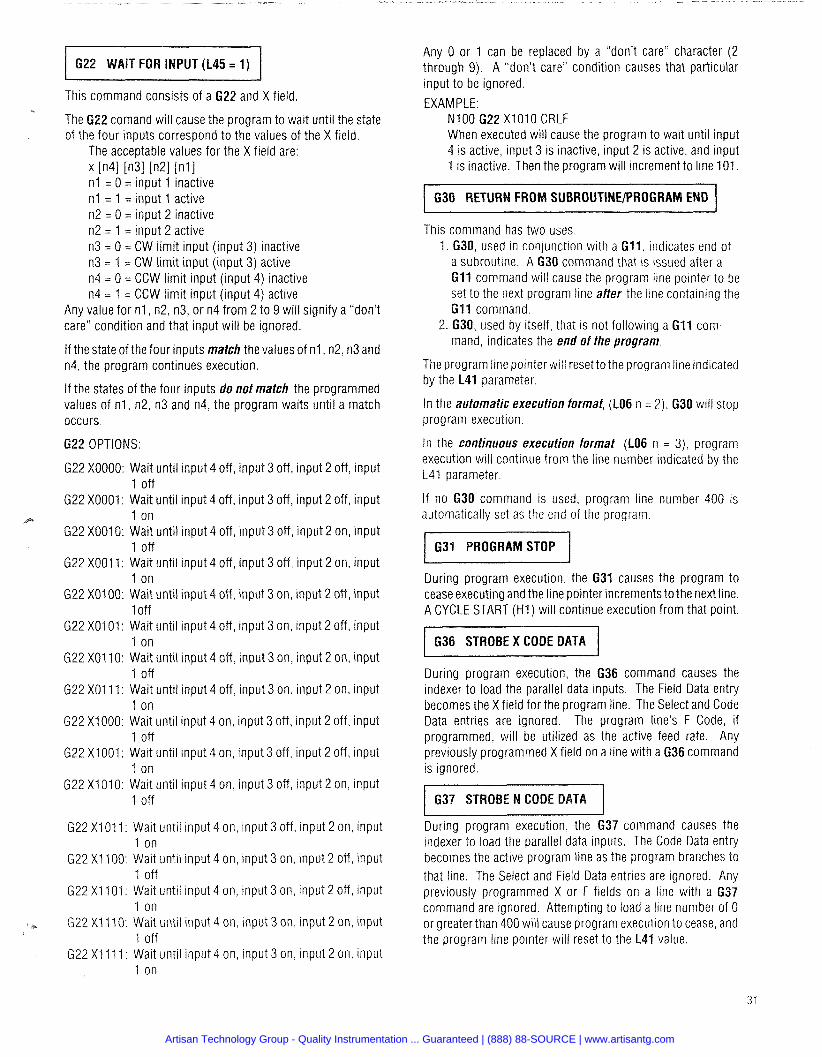
- -
622 WAIT FOR INPUT (L45 = 1)
This command consists of a 622 and X field. &
The 622 comand will cause the program to wait until the state of the four inputs correspond to the values of the X field.
The acceptable values for the X field are: x in41 in31 in21 [ n l I n l = 0 = input 1 inactive n l = 1 = input 1 active n2 = 0 = input 2 inactive n2 = 1 = input 2 active n3 = 0 = CW limit input (input 3) inactive n3 = 1 = CW limit input (input 3) active n4 = 0 = CCW limit input (input 4) inactive n4 = 1 = CCW limit input (input 4) active
Any value for n l , n2, n3, or n4 from 2 to 9 will signify a "don't care" condition and that input will be ignored.
If the state of the four inputs match the values of n1, n2, n3 and n4, the program continues execution.
If the states of the four inputs do not match the programmed values of n l , n2, n3 and n4, the program waits until a match occurs.
622 OPTIONS:
G22 X0000: Wait until input 4 off, input 3 off, input 2 off, input 1 off
G22 X0001: Wait until input 4 off, input 3 off, input 2 off, input 1 on
G22 X007O: Wait until input 4 off, input 3 off, input 2 on, input 1 off
G22 XOO11: Wait until input 4 off, input 3 off, input 2 on, input 1 on
G22 XO100: Wait until input 4 off, input 3 on, input 2 off, input 1 off
G22 X0101: Wait until input 4 off, input 3 on, input 2 off, input 1 on
G22 X0110: Wait until input 4 off, input 3 on, input 2 on, input 1 off
G22 X0111: Wait until input 4 off, input 3 on, input 2 on, input 1 on
G22 X1000: Wait until input 4 on, input 3 off, input 2 off, input 1 off
G22 X1001: Wait until input 4 on, input 3 off, input 2 off, input 1 on
G22 X1010: Wait until input 4 on, input 3 off, input 2 on, input 1 off
G22 XI01 1: Wait until input 4 on, input 3 off, input 2 on, input 1 on
G22 X I 100: Wait until input 4 on, input 3 on, input 2 off, input I off
G22 XI 101 : Wait until input 4 on, input 3 on, input 2 off, input 1 on
G22 Xf 110: Wait until input 4 on, input 3 on, input 2 on, input 1 off
G22 X I 11 1: Wait until input 4 on, input 3 on, input 2 on, input 1 on
Any 0 or 1 can be replaced by a "don't care" character (2 through 9). A "don't care" condition causes that particular input to be ignored.
EXAMPLE: N l 00 622 X l 01 0 CRLF When executed will cause the program to wait until input 4 is active, input 3 is inactive, input 2 is active, and input 1 is inactive. Then the program will increment to line 101.
1 630 RETURN FROM SUBROUTlNElPROGRAM END I This command has two uses.
1. 630, used in conjunction with a G l l , indicates end of a subroutine. A 630 command that is issued after a 611 command will cause the program line pointer to be set to the next program line after the line containing the G l l command.
2. 630, used by itself, that is not following a GI1 com- mand, indicates the end of the program.
The program line pointer will reset to the program line indicated by the L41 parameter.
In the automatic execution format, (LO6 n = 2), 630 will stop program execution.
In the continuous execution format (LO6 n = 3), program execution will continue from the line number indicated by the L41 parameter.
If no 630 command is used, program line number 400 is automatically set as the end of the program.
During program execution, the 631 causes the program to cease executing and the line pointer increments to the next line. A CYCLE START (H l ) will continue execution from that point.
636 STROBE X CODE DATA
During program execution, the G36 command causes the indexer to load the parallel data inputs. The Field Data entry becomes the X field for the program line. The Select and Code Data entries are ignored. The program line's F Code, if programmed, will be utilized as the active feed rate. Any previously programmed X field on a line with a 636 command is ignored.
During program execution, the 637 command causes the indexer to load the parallel data inputs. The Code Data entry becomes the active program line as the program branches to that line. The Select and Field Data entries are ignored. Any previously programmed X or F fields on a line with a 637 command are ignored. Attempting to load a line number of 0 or greater than 400 will cause program execution to cease, and the program line pointer will reset to the L41 value.
Artisan Technology Group - Quality Instrumentation ... Guaranteed | (888) 88-SOURCE | www.artisantg.com
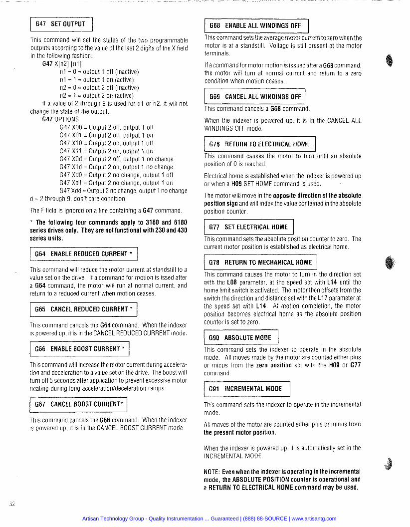
This command will set the states of the two programmable outputs according to the value of the last 2 digits of the X field in the following fashion:
n l = 0 = output 1 off (inactive) n l = 1 = output 1 on (active) n2 = 0 = output 2 off (inactive) n2 = 1 = output 2 on (active)
If a value of 2 through 9 is used for n l or n2, it will not the state of the output.
G47 XOO = Output 2 off, output 1 off G47 X01 = Output 2 off, output 1 on G47 XI0 = Output 2 on, output 1 off G47 X l 1 = Output 2 on, output 1 on G47 XOd = Output 2 off, output 1 no change G47 XI d = Output 2 on, output 1 no change G47 XdO = Output 2 no change, output 1 off G47 Xdl = Output 2 no change, output 1 on G47 Xdd = Output 2 no change, output 1 no change
d = 2 through 9, don't care condition
The F field is ignored on a line containing a 6 4 7 command.
* The following four commands apply to 3180 and 6180 series drives only. They are not functional with 230 and 4 3 0 series units.
LE REDUCED CURRE
This command will reduce the motor current at standstill to a value set on the drive. If a command for motion is issed after
command, the motor will run at normal current, and return to a reduced current when motion ceases.
CEL REDUCED CURRENT * / This command cancels the 6 6 4 command. When the indexer is powered up, it is in the CANCEL REDUCED CURRENT mode.
This command will increase the motor current during accelera- tion and deceleration to a value set on the drive. The boost will turn off 5 seconds after application to prevent excessive motor heating during long acceleration/deceleration ramps.
CEL BOOST CURRENT* I This command cancels the G66 command. When the indexer is powered up, it is in the CANCEL BOOST CURRENT mode.
6 6 8 ENABLE ALL WINDINGS OFF
This command sets the average motor current to zero when the motor is at a standstill. Voltage is still present at the motor terminals.
If a command for motor motion is issued aftera 6 6 8 command, the motor will turn at normal current and return to a zero condition when motion ceases.
This command cancels a G68 command.
When the indexer is powered up, it is in the CANCEL ALL WINDINGS OFF mode.
This command causes the motor to turn until an absolute position of 0 is reached.
Electrical home is established when the indexer is powered up or when a H09 SET HOME command is used.
The motor will move in the opposite direction of the absolute position sign and will index the value contained in the absolute position counter.
6 7 7 SET ELECTRICAL HOME
This command sets the absolute position counter to zero. The current motor position is established as electrical home.
q
This command causes the motor to turn in the direction set with the LO8 parameter, at the speed set with L14 until the home limit switch is activated. The motorthen offsets from the switch the direction and distance set with the L17 parameter at the speed set with L14. At motion completion, the motor position becomes electrical home as the absolute position counter is set to zero.
This command sets the indexer to operate in the absolute mode. All moves made by the motor are counted either plus or minus from the zero position set with the NO9 or 6 7 7 command.
CREMENTAL MODE I This command sets the indexer to operate in the incremental mode.
All moves of the motor are counted either plus or minus from the present motor position.
When the indexer is powered up, it is automatically set in the INCREMENTAL MODE.
OTE: Even when the indexer is operating in the incremental mode, the ABSOLUTE POSITION counter is operational and
RETURN TO ELECTRICAL HOME command may be used.
Artisan Technology Group - Quality Instrumentation ... Guaranteed | (888) 88-SOURCE | www.artisantg.com
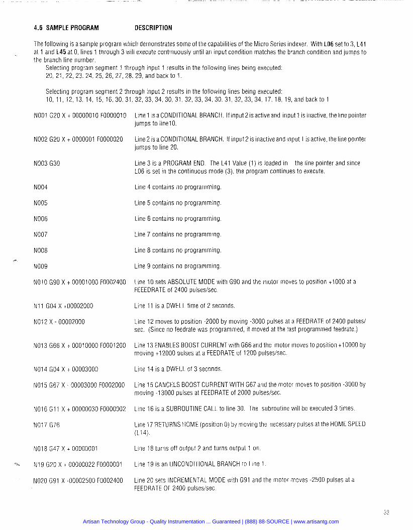
.6 SAMPLE PROGRA DESCRIPTION
The following is a sample program which demonstrates some of the capabilities of the Micro Series indexer. With LO6 set to 3, L41 5 at 0, lines 1 through 3 will execute continuously until an input condition matches the branch condition and jumps to
the branch line number. Selecting program segment 1 through input 1 results in the following lines being executed: 20, 21, 22, 23, 24, 25, 26, 27, 28, 29, and back to 1.
Selecting program segment 2 through input 2 results in the following lines being executed: 10, 11, 12,13,14,15, 16,30,31,32,33,34,30,31,32,33,34,30,31,32,33,34,17,18, 19,andbackto l
NO01 G20 X t 0000001 0 FOOOOOlO Line 1 is a CONDITIONAL BRANCH. If input 2 is active and input 1 is inactive, the line pointer jumps to linelo.
NO02 G20 X t 0000001 F0000020 Line 2 is a CONDITIONAL BRANCH. If input 2 is inactive and input 1 is active, the line pointer jumps to line 20.
Line 3 is a PROGRAM END. The L41 Value (1) is loaded in the line pointer and since LO6 is set in the continuous mode (3), the program continues to execute.
NO04 Line 4 contains no programming
NO05 Line 5 contains no programming.
NO06 Line 6 contains no programming
NO07 Line 7 contains no programming
Line 8 contains no programming.
Line 9 contains no programming.
Line 10 sets ABSOLUTE MODE with G90 and the motor moves to position t1000 at a FEEEDRATE of 2400 pulseslsec.
Line 11 is a DWELL time of 2 seconds
Line 12 moves to position -2000 by moving -3000 pulses at a FEEDRATE of 2400 pulses1 sec. (Since no feedrate was programmed, it moved at the last programmed feedrate.)
Line 13 ENABLES BOOST CURRENT with G66 and the motor moves to position t10000 by moving t12000 pulses at a FEEDRATE of 1200 pulses/sec.
Line 14 is a DWELL of 3 seconds
Line 15 CANCELS BOOST CURRENT WITH G67 and the motor moves to position -3000 by moving -13000 pulses at FEEDRATE of 2000 pulseslsec.
Line 16 is a SUBROUTINE CALL to line 30. The subroutine will be executed 3 times
Line 17 RETURNS HOME (position 0) by moving the necessary pulses at the HOME SPEED (L14).
Line 18 turns off output 2 and turns output 1 on
Line 19 is an UNCONDITIONAL BRANCH to Line 1
Line 20 sets INCREMENTAL MODE with G91 and the motor moves -2500 pulses at a FEEDRATE OF 2400 pulseslsec.
Artisan Technology Group - Quality Instrumentation ... Guaranteed | (888) 88-SOURCE | www.artisantg.com
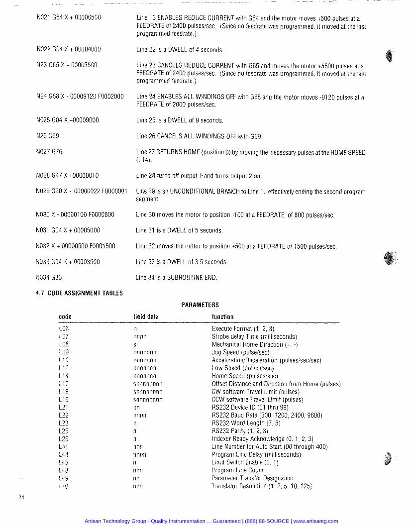
NO21 G64 X t 00000500 Line 13 ENABLES REDUCE CURRENT with G64 and the motor moves t500 pulses at a FEEDRATE of 2400 pulseslsec. (Since no feedrate was programmed, it moved at the last programmed feedrate.)
NO22 GO4 X t 00004000 Lme 22 is a DWELL of 4 seconds.
N23 G65 X + 00005500 Line 23 CANCELS REDUCE CURRENT with G65 and moves the motor t5500 pulses at a FEEDRATE of 2400 pulseslsec. (Since no feedrate was programmed, it moved at the last programmed feedrate.)
N24 G68 X - 00009120 F0002000 Line 24 ENABLES ALL WINDINGS OFF with G68 and the motor moves -9120 pulses at a FEEDRATE of 2000 pulseslsec.
NO25 GO4 X t00009000 Line 25 is a DWELL of 9 seconds.
N26 G69 Line 26 CANCELS ALL WINDINGS OFF with G69
Line 27 RETURNS HOME (position 0) by moving the necessary pulses at the HOME SPEED (L14).
NO28 G47 X t00000010 Line 28 turns off output %and turns output 2 on.
NO29 G20 X t 00000022 F0000001 Line 29 is an UNCONDITIONAL BRANCH to Line 1, effectively ending the second program segment.
NO30 X - 000001 00 F0000800 Line 30 moves the motor to position -100 at a FEEDRATE of 800 pulseslsec.
NO31 GO4 X t 00005000 Line 31 is a DWELL of 5 seconds
NO32 X t 00000500 F0001500 Line 32 moves the motor to position t500 at a FEEDRATE of 1500 pulseslsec.
NO33 GO4 X t 00003500 Line 33 is a DWELL of 3.5 seconds.
NO34 G30 Line 34 is a SUBROUTINE END.
.7 CODE ASSIGNMENT TABLES
PARAMETERS
cod field data function
n nnnn S
nnnnnnn nnnnnnn nnnnnnn nnnnnnn snnnnnnnn snnnnnnnn snnnnnnnn n n nnnn n n n nnn nnnn n nnn nn nnn
Execute Format (1, 2, 3) Strobe delay Time (milliseconds) Mechanical Home Direction ( t , -) Jog Speed (pulselsec) Acceleration/Deceleration (pulses/sec/sec) Low Speed (pulseslsec) Home Speed (pulseslsec) Offset Distance and Direction from Home (pulses) CW software Travel Limit (pulses) CCW software Travel Limit (pulses) RS232 Device ID (01 thru 99) RS232 Baud Rate (300, 1200, 2400,9600) RS232 Word Length (7, 8) RS232 Parity (1, 2, 3) Indexer Ready Acknowledge (0, 1, 2,3) Line Number for Auto Start (00 through 400) Program Line Delay (milliseconds) Limit Switch Enable (0, 1) Program Line Count Parameter Transfer Designation Translator Resolution (1. 2. 5. 10. 125)
Artisan Technology Group - Quality Instrumentation ... Guaranteed | (888) 88-SOURCE | www.artisantg.com
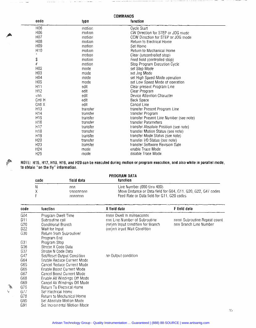
COMMANDS code type function
H06 motion Cycle Start H06 motion CW Direction for STEP or JOG mode H07 motion CCW Direction for STEP or JOG mode H08 motion Return to Electrical Home H09 motion Set Home H I 0 motion Return to Mechanical Home
motion Clear (uncontrolled stop) $ motion Feed hold (controlled stop) # motion Stop Program Execution Cycle H02 mode set Step Mode H03 mode set Jog Mode H 04 mode set High Speed Mode operation H05 mode set Low Speed Mode of operation H I 1 edit Clear present Program Line H I 2 edit Clear Program <nn edit Device Attention Character Cntl H edit Back Space Cntl X edit Cancel Line H I 3 transfer transfer Present Program Line H I 4 transfer transfer Program H i 5 transfer transfer Present Line Number (see note) H I 6 transfer transfer Parameters H I 7 transfer transfer Absolute Position (see note) H I 8 transfer transfer Motion Status (see note) H I 9 transfer transfer Mode Status (see note) H20 transfer transfer I/O Status (see note) H23 transfer transfer Software Revision Date H24 mode enable Trace Mode H25 mode disable Trace Mode
can be executed during motion or program execution, and also while in parallel mode,
PROGRAM DATA code field data function
N nnn Line Number (000 thru 400) X snnnnnnnn Move Distance or Data field for G04, G I 1, G20, G22, G47 codes F nnnnnnn Feed Rate or Data field for GI 1, G20 codes
cod function X field data F field data
nn Output condition
Program Dwell Time nnnn Dwell in milliseconds Subroutine call nnn Line Number of Subroutine nnnn Subroutine Repeat count Conditional Branch (nn)nn Input condition for Branch nnn Branch Line Number Wait for Input (nn)nn Input Wait Condition Return from Subroutine1 Program End Program Stop Strobe X Code Data Strobe N Code Data SettReset Output Condition Enable Reduce Current Mode Cancel Reduce Current Mode Enable Boost Current Mode Cancel Boost Current Mode Enable All Windings Off Mode Cancel All Windings Off Mode Return To Electrical Home Set Electrical Home Return to Mechanical Home Set Absolute Motion Mode Set Incremental Motion Mode
Artisan Technology Group - Quality Instrumentation ... Guaranteed | (888) 88-SOURCE | www.artisantg.com
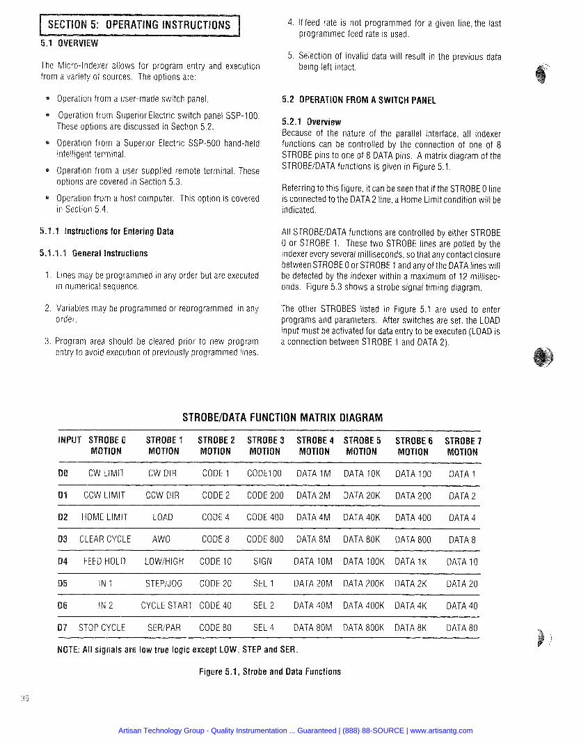
4. If feed rate is not programmed for a given line, the last programmed feed rate is used.
5. Selection of invalid data will result in the previous data The Micro-Indexer allows for program entry and execution being left intact. from a variety of sources. The options are:
Operation from a user-made switch panel.
Operation from Superior Electric switch panel SSP-1 00. These options are discussed in Section 5.2.
Operation from a Superior Electric SSP-500 hand-held intelligent terminal.
Operation from a user supplied remote terminal. These options are covered in Section 5.3.
Operation from a host computer. This option is covered in Section 5.4.
5.1.1 Instructions for Entering Data
5.1.1 .I General Instructions
1. Lines may be programmed in any order but are executed in numerical sequence.
2. Variables may be programmed or reprogrammed in any order.
3. Program area should be cleared prior to new program entry to avoid execution of previously programmed lines.
5.2 OPERATION FROM A SWITCH PANEL
5.2.1 Overview Because of the nature of the parallel interface, all indexer functions can be controlled by the connection of one of 8 STROBE pins to one of 8 DATA pins. A matrix diagram of the STROBEIDATA functions is given in Figure 5.1.
Referring to this figure, it can be seen that if the STROBE 0 line is connected to the DATA 2 line, a Home Limit condition will be indicated.
All STROBEIDATA functions are controlled by either STROBE 0 or STROBE 1. These two STROBE lines are polled by the indexer every several milliseconds, so that any contact closure between STROBE 0 or STROBE 1 and any of the DATA lines will be detected by the indexer within a maximum of 12 millisec- onds. Figure 5.3 shows a strobe signal timing diagram.
The other STROBES listed in Figure 5.1 are used to enter programs and parameters. After switches are set, the LOAD input must be activated for data entry to be executed (LOAD is a connection between STROBE 1 and DATA 2).
CW LIMIT CW DIR CODE 1 CODE1 00 DATA 1 M DATA 1 OK DATA 100 DATA 1 - - -
1 CCW LIMIT CCW DIR CODE 2 CODE 200 DATA2M DATA 20K DATA 200 DATA 2
HOME LIMIT LOAD CODE 4 CODE 400 DATA 4M DATA 40K DATA 400 DATA 4 -
CLEAR CYCLE AWO CODE 8 CODE 800 DATA 8M DATA 80K DATA 800 DATA 8
FEED HOLD LOWIHIGH CODE 10 SIGN DATA 10M DATA 1OOK DATA 1K DATA 10
IN 1 STEP/JOG CODE 20 SEL 1 DATA 20M DATA 200K DATA 2K DATA 20
IN 2 CYCLE START CODE 40 SEL 2 DATA 40M DATA 400K DATA 4K DATA 40
7 STOP CYCLE SERiPAR CODE 80 SEL 4 DATA 80M DATA 800K DATA 8K DATA 80
l i signals are low true logic except LOW, STEP and SER.
Figure 5.1, Strobe and Data Functions
Artisan Technology Group - Quality Instrumentation ... Guaranteed | (888) 88-SOURCE | www.artisantg.com
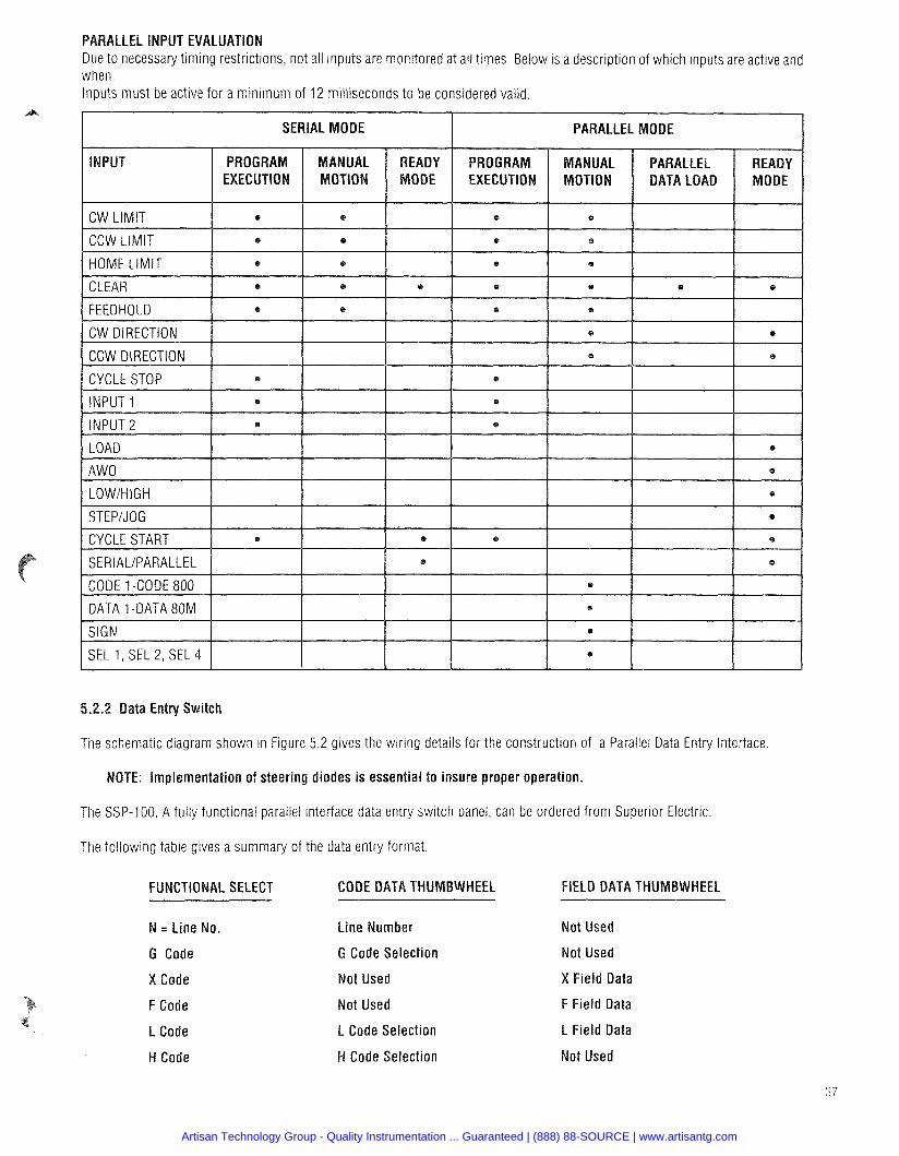
PARALLEL INPUT EVALUATION Due to necessary timing restrictions, not all inputs are monitored at all times. Below is a description of which inputs are active and when. Inputs must be active for a minimum of 12 milliseconds to be considered valid.
PARALLEL MODE I SERIAL MODE
PROGRAM ANUAL PARALLEL READY EXECUTION MOTION DATA LOAD MODE
INPUT READY MODE
I CCW LIMIT I * I e I HOME LIMIT ] @ I e I CLEAR I * \ @ I FEEDHOLD I e I e 1 CW DIRECTION I I
CCW DIRECTION
CYCLE STOP e
I INPUT 1 1 . 1 / INPUT 2 1 . 1
LOAD
1 AWO
CYCLE START e
SERIAUPARALLEL
CODE I -CODE 800 1 DATA 1 -DATA 80M
SIGN
SEL 1, SEL 2, SEL 4 I
The schematic diagram shown in Figure 5.2 gives the wiring details for the construction of a Parallel Data Entry Interface
: Implementation of steering diodes i s essential to insure proper operation.
The SSP-100, A fully functional parallel interface data entry switch panel, can be ordered from Superior Electric
The following table gives a summary of the data entry format
FIELD DATA THUMBWHEEL FUNCTIONAL SELECT CODE DATA THUMBWHEEL
= Line No.
Code
Code
F Code
L Code
W Code
Line Number
G Code Selection
Not Used
Not Used
L Code Selection
W Code Selection
ot Used
ot Used
X Field Data
F Field Data
L Field Data
ot Used
Artisan Technology Group - Quality Instrumentation ... Guaranteed | (888) 88-SOURCE | www.artisantg.com
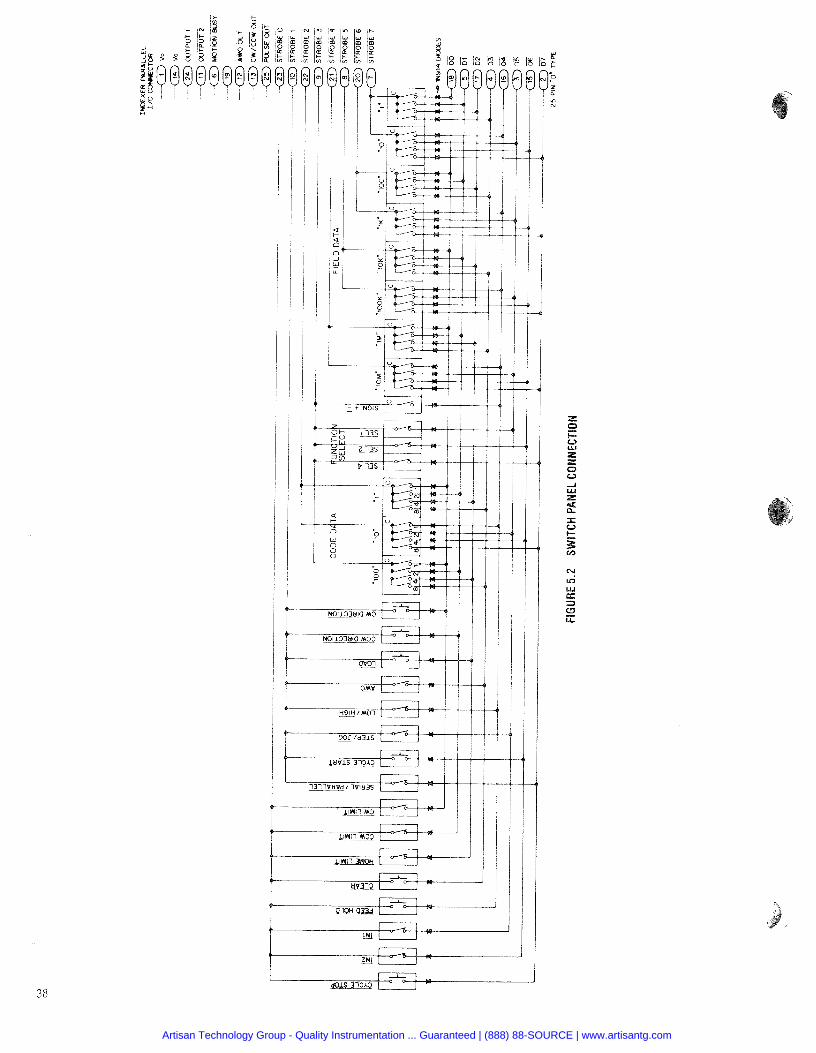
Artisan Technology Group - Quality Instrumentation ... Guaranteed | (888) 88-SOURCE | www.artisantg.com
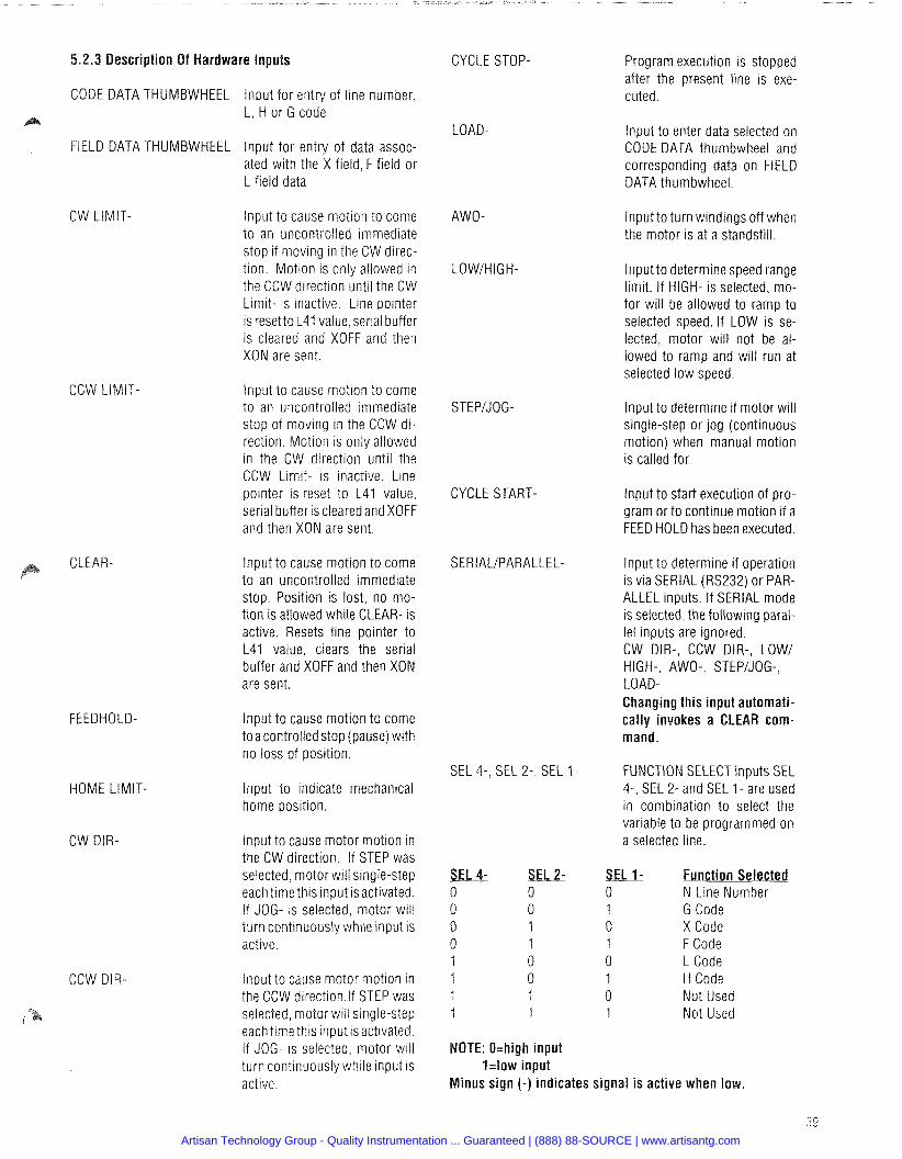
5.2.3 Description Of Hardware Inputs
CODE DATA THUMBWHEEL lnput for entty of line number, L, H or G code
FIELD DATA THUMBWHEEL lnput for entry of data assoc- ated with the X field, F field or L field data
CW LIMIT- Input to cause motion to come to an uncontrolled immediate stop if moving in the CW direc- tion. Motion is only allowed in the CCW direction until the CW Limit- is inactive. Line pointer is resetto L41 value, serial buffer is cleared and XOFF and then XON are sent.
CCW LIMIT-
CLEAR-
FEEDHOLD-
HOME LIMIT-
CW DIR-
CCW DIR-
lnput to cause motion to come to an uncontrolled immediate stop of moving in the CCW di- rection. Motion is only allowed in the CW direction until the CCW Limit- is inactive. Line pointer is reset to L41 value, serial buffer is cleared and XOFF and then XON are sent.
lnput to cause motion to come to an uncontrolled immediate stop. Position is lost, no mo- tion is allowed while CLEAR- is active. Resets line pointer to L41 value, clears the serial buffer and XOFF and then XON are sent.
lnput to cause motion to come toacontrolled stop (pause) with no loss of position.
lnput to indicate mechanical home position.
Input to cause motor motion in the CW direction. If STEP was selected, motor will single-step each time this input is activated. If JOG- is selected, motor will turn continuously while input is active.
lnput to cause motor motion in the CCW direction.lf STEP was selected, motor will single-step each time this input isactivated. If JOG- is selected, motor will turn continuously while input is active.
CYCLE STOP- Program execution is stopped after the present line is exe- cuted.
LOAD-
AWO-
lnput to enter data selected on CODE DATA thumbwheel and corresponding data on FIELD DATA thumbwheel.
lnput to turn windings off when the motor is at a standstill.
Input to determine speed range limit. If HIGH- is selected, mo- tor will be allowed to ramp to selected speed. If LOW is se- lected, motor will not be al- lowed to ramp and will run at selected low speed.
STEPIJOG- Input to determine if motor will single-step or jog (continuous motion) when manual motion is called for.
CYCLE START- Input to start execution of pro- gram or to continue motion if a FEED HOLD has been executed.
SERIALIPARALLEL- Input to determine if operation is via SERIAL (RS232) or PAR- ALLEL inputs. If SERIAL mode is selected, the following paral- lel inputs are ignored. CW DIR-, CCW DIR-, LOW/ HIGH-, AWO-, STEPJJOG-, LOAD- Changing this input automati- cally invokes a CLEAR com- mand.
SEL 4-, SEL 2-, SEL 1 - FUNCTION SELECT inputs SEL 4-, SEL 2- and SEL 1 - are used in combination to select the variable to be programmed on a selected line.
Function Selected N Line Number G Code X Code F Code L Code H Code Not Used Not Used
NOTE: O=high input l= low input
inus sign (-) indicates signal is active when low.
Artisan Technology Group - Quality Instrumentation ... Guaranteed | (888) 88-SOURCE | www.artisantg.com
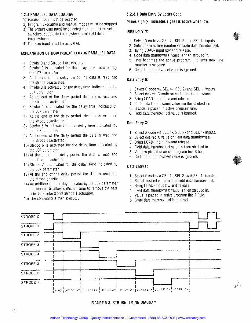
PARALLEL DATA LOADING 1) Parallel mode must be selected 2) Program execution and manual modes must be stopped 3) The proper data must be selected via the function select
switches, code data thumbwheels and field data thurnbwheels.
4) The load input must be activated.
OF HOW INDEXER LOADS PARALLEL DATA
Strobe 0 and Strobe 1 are disabled. Strobe 2 is activated for the delay time indicated by the LO7 parameter. At the end of the delay period the data is read and the strobe deactivated. Strobe 3 is activated for the delay time indicated by the LO7 parameter. At the end of the delay period the data is read and the strobe deactivated. Strobe 4 is activated for the delay time indicated by the LO7 parameter. At the end of the delay period the data is read and the strobe deactivated. Strobe 5 is activated for the delay time indicated by the LO7 parameter. At the end of the delay period the date is read and the strobe deactivated.
10) Strobe 6 is activated for the delay time indicated by the LO7 parameter.
11) At the end of the delay period the data is read and the strobe deactivated.
12) Strobe 7 is activated for the delay time indicated by the LO7 parameter.
13) At the end of the delay period the data is read and the strobe deactivated.
14) An additional time delay indicated by the LO7 parameter is executed to allow sufficient time to remove the data prior to Strobe 0 and Strobe 1 actuation.
15) The command is then executed.
STROBE 0
STROBE 1
STROBE 2
STROBE 3
STROBE 4
STROBE 5
STROBE 6
STROBE 7
5.2.4.1 Data Entry By Letter Code
inus sign (-) indicates signal is active when low.
Data Entry N:
Select N code via SEL 4-, SEL 2- and SEL 1- ~nputs. Select desired line number on code data thumbwheel. Bring LOAD- input low and release.
Code data thumbwheel value is then strobed in. This becomes the active program line until new line number is selected. Field data thumbwheel value is ignored.
Data Entry G:
1. Select G code via SEL 4-, SEL 2- and SEL 1- inputs 2. Select desired G code on code data thumbwheel. 3. Bring LOAD- input low and release. 4. Code data thumbwheel value are the strobed in. 5. G code is placed in active program line. 6. Field data thumbwheel value is ignored.
Data Entry X:
1. Select X code via SEL 4-, SEL 2- and SEL 1 - inputs. 2. Select desired X value on field data thumbwheel. 3. Bring LOAD- input low and release. 4. Field data thumbwheel value is then strobed in. 5. Value is placed in active program line X field. 6. Code data thumbwheel value is ignored.
Data Entry F:
1. Select F code via SEL 4-, SEL 2- and SEL 1 - inputs. 2. Select desired value on the field data thumbwheel. 3. Bring LOAD- input low and release. 4. Field data thumbwheel value is then strobed in. 5. Value is placed in active program line F field. 6. Code data thumbwheel is ignored.
FIGURE 5.3, STROBE TIMING DIAGRAM
Artisan Technology Group - Quality Instrumentation ... Guaranteed | (888) 88-SOURCE | www.artisantg.com
code via SEL 4-, SEL 2- and SEL 1- inputs. 2. Select desired L code data on code data thumbwheel. 3. Select associated value on field data thumbwheel. 4. Bring LOAD- input low and release. 5. Code data thurnbwheel value is then strobed in. 6. Field data thumbwheel value is then strobed in. 7. L code is entered.
1. Select H code via SEL 4-, SEL 2- and SEL 1 - inputs 2. Select desired H code on code data thumbwheel. 3. Bring LOAD- input low and release. 4. Code data thumbwheel value is then strobed in. 5. H code is executed. 6. Field data thumbwheel is ignored.
: The following H codes cannot b el mode: H2, H3, H4, H5, H6 and
Manual motion is possible whenever a program is not being executed. The STEPIJOG- input and the LOWIHIGH- input will determine the response to the CW DIR- and CCW DIR- inputs becoming active. The absolute position counter is maintained.
Program Execution is accomplished by activating the CYCLE START- input and releasing. The program then executes based on the L parameters.
uts Accessed Through The External Parallel I10
These outputs are open collectors. They must be pulled up to an external voltage source (maximum t24Vdc) through a series resistor to limit the sink current to a maximum of 40 milliamperes.
OUTPUT 1 -, OUTPUT 2- Programmable outputs con- trolled through use of G47 code.
ALL WINDINGS OFF OUT- Output indicating the status of the ALL WINDINGS OFF- mode.
CWICCW- OUT Output indicating the direction of motor motion.
MOTION BUSY OUT- Output indicating when any type of motion is occurring.
PULSE OUT- Output of the pulses being ap plied to the drive.
FROM A REMOTE TER
This section contains information pertaining to operating the indexer from a remote terminal via the RS232 serial port.
.2 Connections and Intedace 9-prn ser~al rnterface connector can be used to connect a
remote termrnal to the Indexer for programming and program t execution
When any other type of remote terminal is used with the indexer, the baud rate must be set correctly so that the indexer will match the terminal. This parameter is set with the L22, L23 and L25 commands. See the Command Description section for the applicable values and defaults.
NOTE: The baud rate, word length and parity default set- tings are correct for operation with the Superior Electric hand-held remote terminal SSP-500.
If another type of remote terminal is used which has a baud rate other than 9600 baud, the terminal will not be able to communicate with the indexer. A compatible terminal will have to be used to set the baud rate or, alternatively, a switch panel (such as an SSP-1OO)can be used to set the indexer's baud rate, etc. (See Section 5.2.1 for a description of the switch panel operation).
5.4 OPERATION FROM A HOST COMPUTER The hardware connections fora host computer are the same as those for a remote terminal. The connection is made through the 9-pin serial interface connector.
An IBM compatible program (on a 5.25" floppy disk) that has editing, manual motion and program execution modes of operation to facilitate Micro Series indexer functions is avail- able from Superior Electric. Local and remote modes allow programs to be developed off-line in the IBM PC and later loaded into the indexer.
Alternatively, a commercially available communications pro- gram (such as "Crosstalk", from Digital Communications Asso- ciates. Inc.) may be run on the PC to configure it as a remote terminal.
To interface with an IBM PC, the connections must be config- ured as follows:
IBM (25-pin "D" Connector) Positioner (9-pin "D" Connector) - - - -- - - - -- -
Pin Number -- Pin Number - 2 > 3 Rece~ve 3 > 2 Cham O u t 7 - -- > 4 S~gnal Common
Following are three sample IBM PC compatible programs to display the ease of indexer/host computer software interfacing. Program 1 uploads an indexer program to the PC disk. Pro- gram 2 downloads a program from the PC disk to the indexer: and program 3 sets up interactive communications between the PC and the indexer. Enter BASIC with the following:
The SSP-500, a hand-held intelligent terminal available from Superior Electric, can be used for debugging, loading and executing indexer programs.
Artisan Technology Group - Quality Instrumentation ... Guaranteed | (888) 88-SOURCE | www.artisantg.com
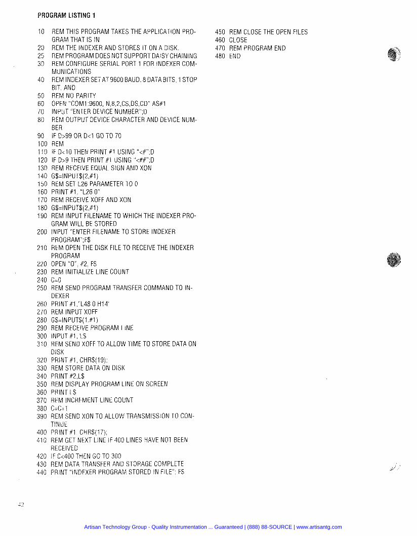
10 REM THIS PROGRAM TAKES THE APPLICATION PRO- 450 REM CLOSE THE OPEN FILES GRAM THAT IS IN 460 CLOSE
20 REM THE INDEXER AND STORES IT ON A DISK 470 REM PROGRAM END 25 REM PROGRAM DOES NOT SUPPORT DAISY CHAINING 480 END 3 0 REM CONFIGURE SERIAL PORT 1 FOR INDEXER COM-
MUNICATIONS 40 REM INDEXER SET AT9600 BAUD, 8 DATA BITS, 1 STOP
BIT, AND 50 REM NO PARITY 6 0 OPEN "COMI 9600, N,8,2,CS,DS,CDH AS# 1 70 INPUT "ENTER DEVICE NUMBERn,D 80 REM OUTPUT DEVICE CHARACTER AND DEVICE NUM-
BER 9 0 IF D>99 OR D<1 GO TO 70 100 REM 110 IF D<10 THEN PRlNT #1 USING "<#",D 120 IF D>9 THEN PRlNT #l USING "<##",D 130 REM RECEIVE EQUAL SIGN AND XON 140 G$=INPUT$(2,#1) 150 REM SET L26 PARAMETER TO 0 160 PRlNT #1, "L26 0" 170 REM RECEIVE XOFF AND XON 180 G$=INPUT$(2,# 1) 190 REM INPUT FILENAME TO WHICH THE INDEXER PRO-
GRAM WILL BE STORED 200 INPUT "ENTER FILENAME TO STORE INDEXER
PROGRAMn,F$ 210 REM OPEN THE DlSK FILE TO RECEIVE THE INDEXER
PROGRAM 220 OPEN "OH, #2, F$ 230 REM INITIALIZE LlNE COUNT 240 C=O 250 REM SEND PROGRAM TRANSFER COMMAND TO IN-
DEXER 260 PRlNT #1,"L48 0 H I 4 270 REM INPUT XOFF 280 G$=INPUT$(l ,#1) 290 REM RECEIVE PROGRAM LlNE 300 INPUT #l , L$ 310 REM SEND XOFF TO ALLOW TIME TO STORE DATA ON
DISK 320 PRlNT # I , CHR$(I 9), 330 REM STORE DATA ON DlSK 340 PRINT #2,L$ 350 REM DISPLAY PROGRAM LlNE ON SCREEN 360 PRlNT L$ 370 REM INCREMENT LlNE COUNT 380 C=C+1 390 REM SEND XON TO ALLOW TRANSMISSION TO CON-
TINUE 400 PRlNT #1, CHR$(17), 410 REM GET NEXT LINE IF 400 LINES HAVE NOT BEEN
RECEIVED 420 IF C<400 THEN GO TO 300 430 REM DATA TRANSFER AND STORAGE COMPLETE 440 PRlNT "INDEXER PROGRAM STORED IN FILE'' F$
Artisan Technology Group - Quality Instrumentation ... Guaranteed | (888) 88-SOURCE | www.artisantg.com
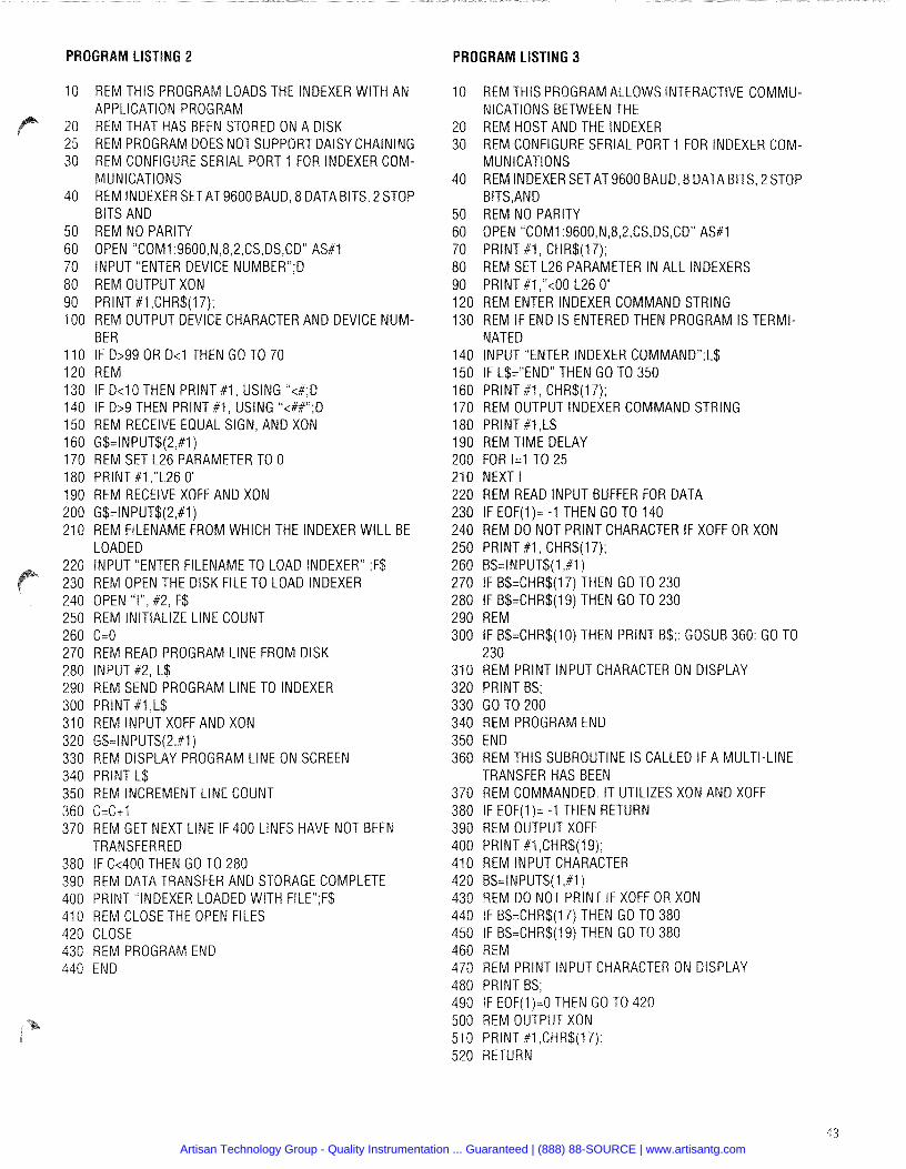
REM THIS PROGRAM LOADS THE INDEXER WlTH AN APPLICATION PROGRAM REM THAT HAS BEEN STORED ON A DISK REM PROGRAM DOES NOT SUPPORT DAISY CHAINING REM CONFIGURE SERIAL PORT 1 FOR INDEXER COM- MUNICATIONS REM INDEXER SET AT9600 BAUD, 8 DATA BITS, 2 STOP BITS AND REM NO PARITY OPEN "COM1:9600,N,8,2,CS,DS,CDU AS#l INPUT "ENTER DEVICE NUMBERn;D REM OUTPUT XON PRlNT # I ,CHR$(17); REM OUTPUT DEVICE CHARACTER AND DEVICE NUM- BER IF D>99 OR D<1 THEN GO TO 70 REM IF D<lO THEN PRlNT #1, USING "<#;D IF D>9 THEN PRlNT #1, USING "<##";D REM RECEIVE EQUAL SIGN, AND XON G$=INPUT$(2,#1) REM SET L26 PARAMETER TO 0 PRlNT #1 ,"L26 0" REM RECEIVE XOFF AND XON G$=INPUT$(2,#1) REM FILENAME FROM WHICH THE INDEXER WILL BE LOADED INPUT "ENTER FILENAME TO LOAD INDEXER" ;F$ REM OPEN THE DISK FILE TO LOAD INDEXER OPEN "I", #2, F$ REM INITIALIZE LlNE COUNT C=O REM READ PROGRAM LlNE FROM DISK INPUT #2, L$ REM SEND PROGRAM LlNE TO INDEXER PRlNT #1 ,L$ REM INPUT XOFF AND XON G$=INPUT$(2,# 1 ) REM DISPLAY PROGRAM LlNE ON SCREEN PRlNT L$ REM INCREMENT LlNE COUNT C = C t l REM GET NEXT LINE IF 400 LINES HAVE NOT BEEN TRANSFERRED IF (2400 THEN GO TO 280 REM DATA TRANSFER AND STORAGE COMPLETE PRlNT "INDEXER LOADED WlTH FILEn$$ REM CLOSE THE OPEN FILES CLOSE REM PROGRAM END END
PROGRAM LISTING 3
REM THlS PROGRAM ALLOWS INTERACTIVE COMMU- NICATIONS BETWEEN THE REM HOST AND THE INDEXER REM CONFIGURE SERIAL PORT 1 FOR INDEXER COM- MUNICATIONS REM INDEXER SET AT 9600 BAUD, 8 DATA BITS, 2 STOP BITS,AND REM NO PARITY OPEN T O M 1 :9600,N,8,2,CS,DS,CD" AS#1 PRlNT # I , CHR$(17); REM SET L26 PARAMETER IN ALL INDEXERS PRlNT #1,"<00 L26 0" REM ENTER INDEXER COMMAND STRING REM IF END IS ENTERED THEN PROGRAM IS TERMI- NATED INPUT "ENTER INDEXER COMMANDn;L$ IF L$="ENDn THEN GO TO 350 PRlNT # I , CHR$(17); REM OUTPUT INDEXER COMMAND STRING PRINT #1 ,L$ REM TIME DELAY FOR I=1 TO 25 NEXT l REM READ INPUT BUFFER FOR DATA IF EOF(1)= -1 THEN GO TO 140 REM DO NOT PRlNT CHARACTER IF XOFF OR XON PRlNT # I , CHR$(17); B$=INPUT$(l,#l ) IF B$=CHR$(17) THEN GO TO 230 IF B$=CHR$(19) THEN GO TO 230 REM IF B$=CHR$(10) THEN PRINT B$;: GOSUB 360: GO TO 230 REM PRlNT INPUT CHARACTER ON DISPLAY PRlNT B$; GO TO 200 REM PROGRAM END END REM THlS SUBROUTINE IS CALLED IF A MULTI-LINE TRANSFER HAS BEEN REM COMMANDED. IT UTILIZES XON AND XOFF IF EOF(l)= -1 THEN RETURN REM OUTPUT XOFF PRlNT #1 ,CHR$(19); REM INPUT CHARACTER B$=INPUT$(1,#1) REM DO NOT PRINT IF XOFF OR XON IF B$=CHR$(l 7) THEN GO TO 380 IF B$=CHR$(l 9) THEN GO TO 380 REM REM PRlNT INPUT CHARACTER ON DISPLAY PRlNT B$; IF EOF(I)=O THEN GO TO 420 REM OUTPUT XON PRlNT # I ,CHR$(17), RETURN
Artisan Technology Group - Quality Instrumentation ... Guaranteed | (888) 88-SOURCE | www.artisantg.com
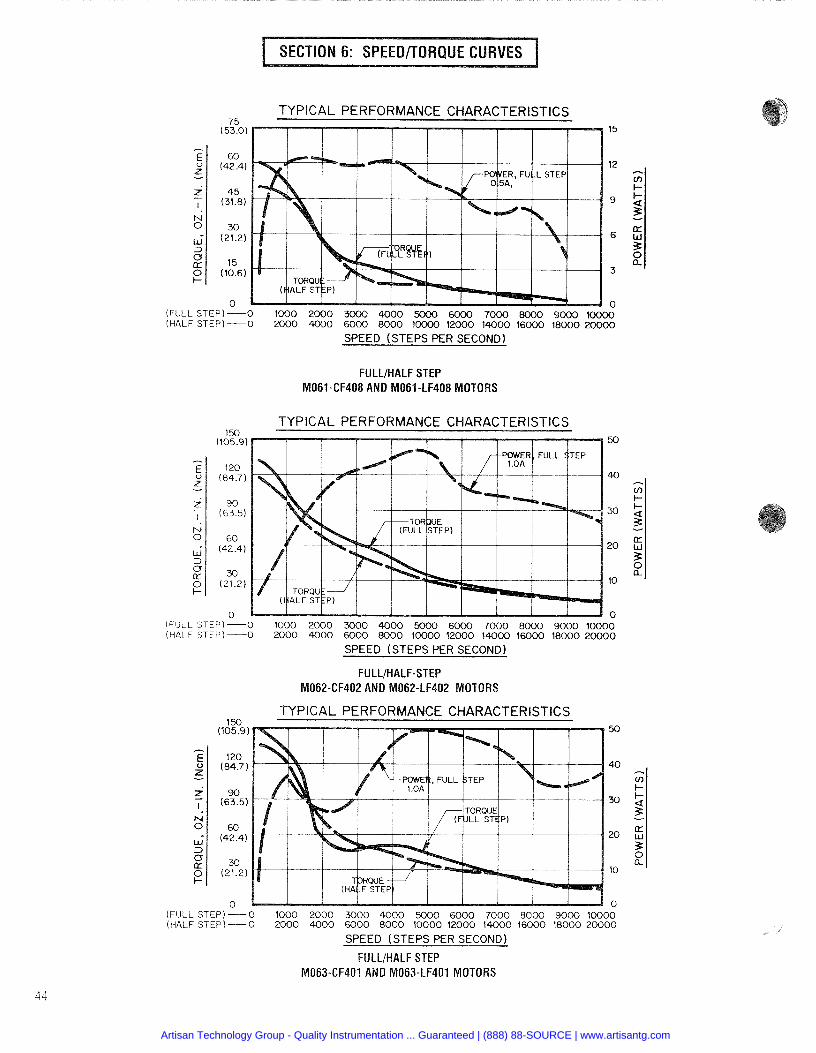
TYPICAL PERFORMANCE CHARACTERISTICS
- (FULL STEP)-0 1 0 0 0 2 0 0 0 3000 4000 5000 6000 7000 8000 9000 XXXX) (HALF STEP) -0 X X X ) 4 0 0 0 6 0 0 0 8 0 0 0 10000 12000 1 4 0 0 0 16000 18000 20000
SPEED (STEPS PER SECOND)
FULLIHALF STEP M061-CF408 AND M061-LF408 MOTORS
3
TYPICAL PERFORMANCE CHARACTERISTICS
(FULL STEP)-0 1000 2 0 0 0 3 0 0 0 4000 5000 6 0 0 0 7 0 0 0 8 0 0 0 9000 1 0 0 0 0 (HALF STEP)-0 2000 4000 6000 8000 1 0 0 0 0 1 2 0 0 0 1 4 0 0 0 16000 1 8 0 0 0 2 0 0 0 0
SPEED (STEPSPER SECOND)
FULLIHALF-STEP M062-CF402 AND M062-LF402 MOTORS
TYPICAL PERFOR ANCE CHARACTERISTICS
(FULL STEP) - 0 1 0 0 0 2000 3000 4000 5000 6 0 0 0 7 0 0 0 8 0 0 0 9 0 0 0 1 0 0 0 0 (HALF STEP)-0 '2000 4000 6000 8 0 0 0 1 0 0 0 0 12000 1 4 0 0 0 1 6 0 0 0 18000 2 0 0 0 0
SPEED (STEPS PER SECOND)
FULLtHALF STEP M063-CF401 AND M063-LF401 MOTORS
Artisan Technology Group - Quality Instrumentation ... Guaranteed | (888) 88-SOURCE | www.artisantg.com
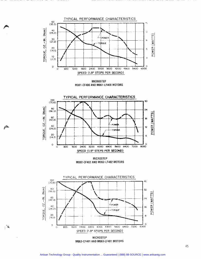
=,, TYPICAL PERFORMANCE CHARACTERISTICS
SPEED (1.8" STEPS PER SECOND)
MICROSTEP M061-CF408 AND M061-LF408 MOTORS
TYPICAL PERFORMANCE CHARACTERISTICS
SPEED ( 1 . 8 O STEPS PER SECOND)
MICROSTEP M062-CF402 AND M062-LF402 MOTORS
.,.,. TYPICAL PERFORMANCE CHARACTERISTICS
SPEED (1.8" STEPS PER SECOND)
MICROSTEP M063-CF401 AND M063-LF401 MOTORS
Artisan Technology Group - Quality Instrumentation ... Guaranteed | (888) 88-SOURCE | www.artisantg.com
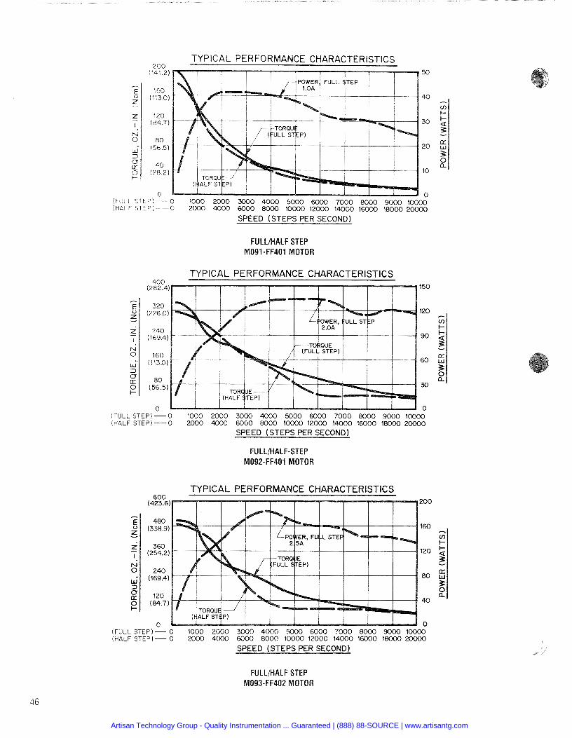
7 nn TYPICAL PERFORMANCE CHARACTERISTICS
50
40
30
20
10
0 (FULL STEP) - 0 1000 2000 3000 4000 5000 6000 7000 8000 9000 10000 (hALF STEP - 0 2000 4000 6000 8000 10000 12000 14000 16000 18000 20000
SPEED (STEPS PER SECOND)
FULLIHALF STEP M091-FF401 MOTOR
TYPICAL PERFORMANCE CHARACTERISTICS 150
120 - cn I-
90 & 3 -
60 E 3
30 B
n (FULL STEP) - 0 1000 2000 3000 4000 5000 6000 7000 8000 9000 1 O W (HALF STEP) - 0 2000 4000 6000 8000 10000 12000 14000 16000 1sOOO 20000
(FUL (HAL
SPEED (STEPSPERSECOND)
FULLIHALF-STEP M092-FF401 MOTOR
fino TYPICAL PERFORMANCE CHARACTERISTICS
SPEED (STEPSPER SECOND)
FULLIHALF STEP M093-FF402 MOTOR
Artisan Technology Group - Quality Instrumentation ... Guaranteed | (888) 88-SOURCE | www.artisantg.com
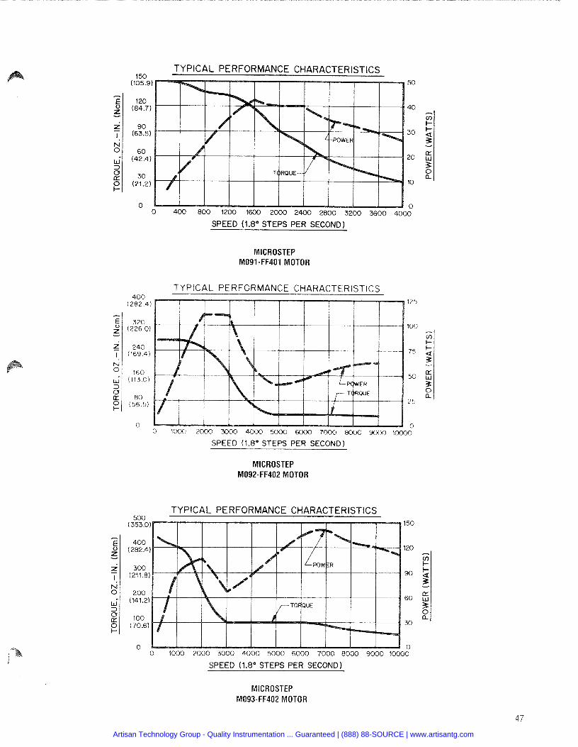
4 5n TYPICAL PERFORMANCE CHARACTERISTICS
SPEED (1.8" STEPS PER SECOND)
MICROSTEP M091-FF401 MOTOR
T Y P I C A L PERFORMANCE CHARACTERISTICS 4 0 0
(282.4) 125
320 (226.0) 100 -
cn k-
240 (169.4) 75 + 4 -.
160 (113.0)
50 & 3 0
80 a ( 5 6 5)
25
0 0 0 1 0 0 0 2000 3000 4000 5000 6000 7000 800Ci 9000 1 m
SPEED (1.8" STEPS PER SECOND)
MICROSTEP M092-FF402 MOTOR
cnn TYPICAL PERFORMANCE CHARACTERISTICS
SPEED (1.8" STEPS PER SECOND)
MICROSTEP M093-FF402 MOTOR
Artisan Technology Group - Quality Instrumentation ... Guaranteed | (888) 88-SOURCE | www.artisantg.com
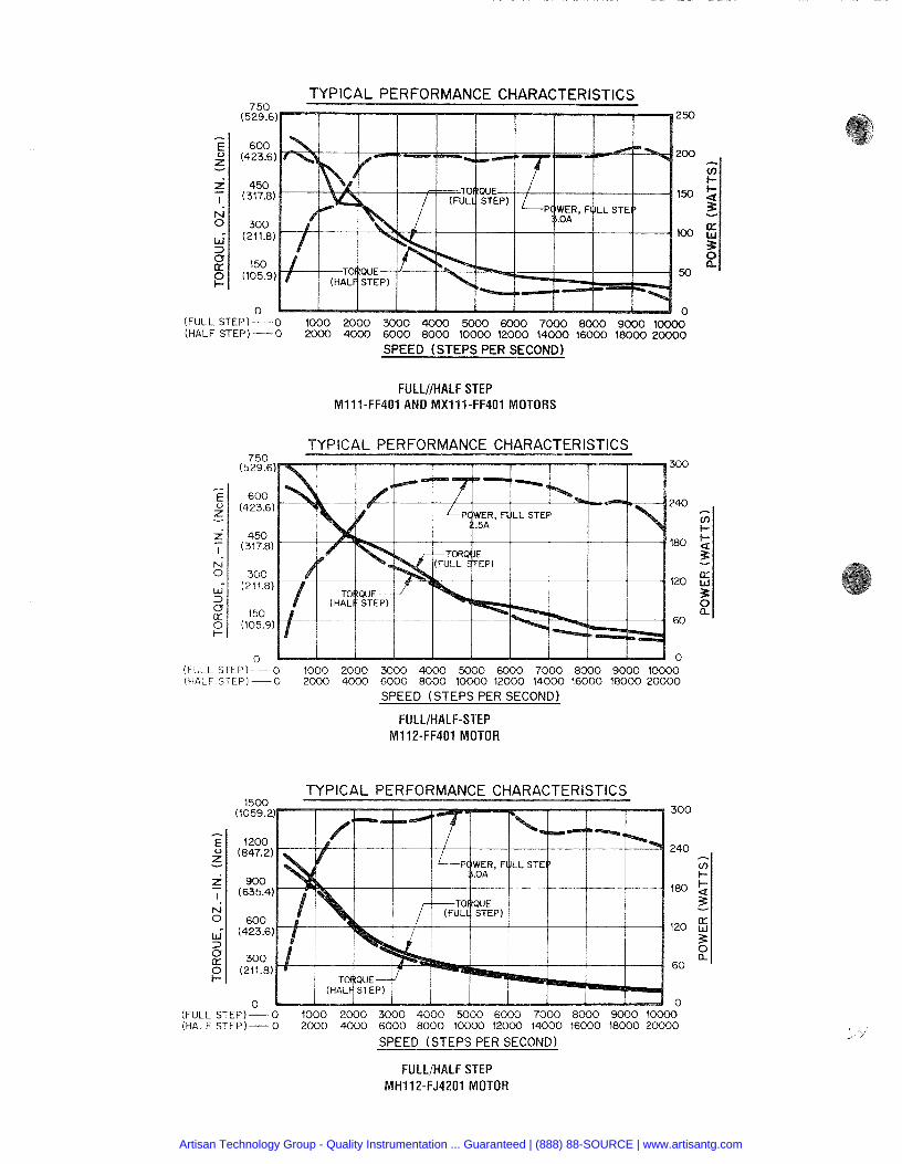
TYPICAL PERFORMANCE CHARACTERISTICS 750
(529.6) 250
SPEED (STEPS PER SECOND)
- E 2 - z I. N 0
" 3
,o 0 k-
FULLNHALF STEP M111-FF401 AND MX111-FF401 MOTORS
600 (423.6) 200
450 (317.8) 150
300 (211.8) 100
150 (105.9) 50
- 7 -
TYPICAL PERFORMANCE CHARACTERISTICS
0 0 (FULL STEP)-0 1000 2000 3000 4000 5000 6000 7000 8000 9000 10000 (HALF STEP) - 0 2000 4000 6000 8000 10000 12000 14000 16000 18000 20000
1500 TYPICAL PERFORMANCE CHARACTERISTICS
300
240
180
120
60
0 (FULL STEP) - 0 1000 2000 3000 4000 5000 6000 7000 8000 9000 10000 (HALF STEP)- 0 2000 4000 6000 8000 10000 12000 14000 16000 18000 20000
SPEED (STEPS PER SECOND)
/ 3u (529.6) 300
FULLIHALF STEP MH112-FJ4201 MOTOR
E ,U - z I.
N 0
13
600 (423.6) 240
450 (317.8) 180
300 (211.8) 120
150 (105.9) 60
0 0 (FULL STEP) -0 1000 2000 3000 4000 5000 6000 7000 8000 9000 10000 (HALF STEP) - 0 X X X ) 4000 6000 8000 10000 12000 14000 16000 18000 20000
SPEED (STEPS PER SECOND)
FULLIHALF-STEP M112-FF401 MOTOR
Artisan Technology Group - Quality Instrumentation ... Guaranteed | (888) 88-SOURCE | www.artisantg.com
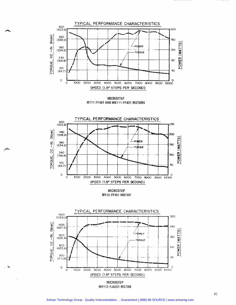
0 1000 2000 3000 4000 5000 6000 7000 8000 9000 IOOOO-
SPEED (1.8'' STEPS PER SECOND)
cnn TYPICAL PERFORMANCE CHARACTERlSTlCS
MICROSTEP M111-FF401 AND MX111-FF401 MOTORS
TYPICAL PERFORMANCE CHARACTERISTICS 250
150
100
50
0 1000 2000 3000 4000 5000 6000 7000 eOOO 9000 loo00
SPEED (1.8" STEPS PER SECOND)
MICROSTEP M112-FF401 MOTOR
TYPICAL PERFORMANCE CHARACTERISTICS
SPEED (1.8" STEPS PER SECOND 1
MICROSTEP MH112-FJ4201 MOTOR
Artisan Technology Group - Quality Instrumentation ... Guaranteed | (888) 88-SOURCE | www.artisantg.com
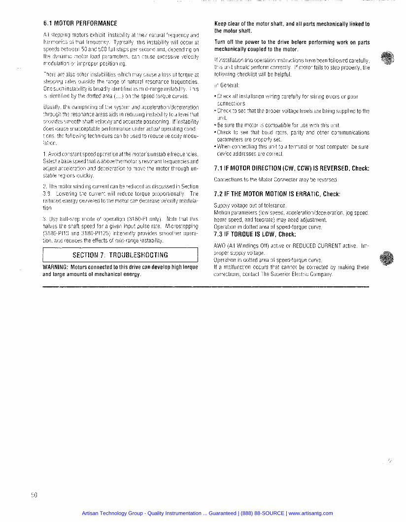
6.1 MOTOR PERFORMANCE
All stepping motors exhibit instability at their natural frequency and harmonics of that frequency Typically this instability will occur at speeds between 50 and 500 full steps per second and depending on the dynamic motor load parameters can cause excessive velocity modulation or improper positioning
There are also other instabilities which may cause a loss of torque at stepping rates outside the range of natural resonance frequencies. One such instability is broadly identified as mid-range instability. This is identified by the dotted area ( . . . . I on the speed torque curves.
Usually the dampening of the system and accelerationideceleration through the resonance areas aids in reducing instability to a level that prov~des smooth shaft velocity and accurate positioning If instability does cause unacceptable performance under actual operating condi- tions, the following techniques can be used to reduce velocity modu- lation
1 Avoid constant speed operation at the motor s unstable frequencies Select a base speed that is above the motor's resonant frequencies and adjust acceleration and deceleration to move the motor through un- stable regions quickly
2 The motor winding current can be reduced as discussed in Section 3.8 Lowering the current will reduce torque proportionally. The reduced energy delivered to the motor can decrease velocity modula- tion
3. Use half-step mode of operation (3180-PI only). Note that this halves the shaft speed for a given input pulse rate. Microstepping (3180-PI10 and 3180-P1125) inherently provides smoother opera- t ion. and reduces the effects of mid-range instability.
WARNING: Motors connected to this drive can develop high torque and large amounts of mechanical energy.
Keep clear of the motor shaft, and al l parts mechanically linked to the motor shaft.
Turn off the power to the drlve before perform~ng work on parts mechan~cally coupled to the motor.
if installation and operation instructions have been followed carefully this unit should perform correctly If motor fails to step properly the following checklist will be helpful
In General:
C h e c k all installation wir ing carefully for wiring errors or poor connections
C h e c k to see that the proper voltage levels are being supplled to the unit
B e sure the motor is compatible for use with this unit *Check to see that baud rates parity and other communications
parameters are properly set *When connecting thls unit to a terminal or host computer be sure
device addresses are correct
7.1 IF MOTOR DIRECTION (CW, CGW) IS REVERSED, Check:
Connect~ons to the Motor Connector may be reversed
7.2 IF THE MOTOR MOTION IS ERRATIC, Check:
Supply voltage out of tolerance. Motion parameters ( low speed, accelerationldeceleration. jog speed, home speed, and feedrate) may need adjustment. Operation in dotted area of speed-torque curve. 7.3 IF TORQUE IS LOW, Check:
AWO (All Windings Off) active o r REDUCED CURRENT active. Im- proper supply voltage. Operation i n dotted area of speed-torque curve. If a malfunction occurs that cannot be corrected by making these corrections, contact The Superior Electric Company.
Artisan Technology Group - Quality Instrumentation ... Guaranteed | (888) 88-SOURCE | www.artisantg.com
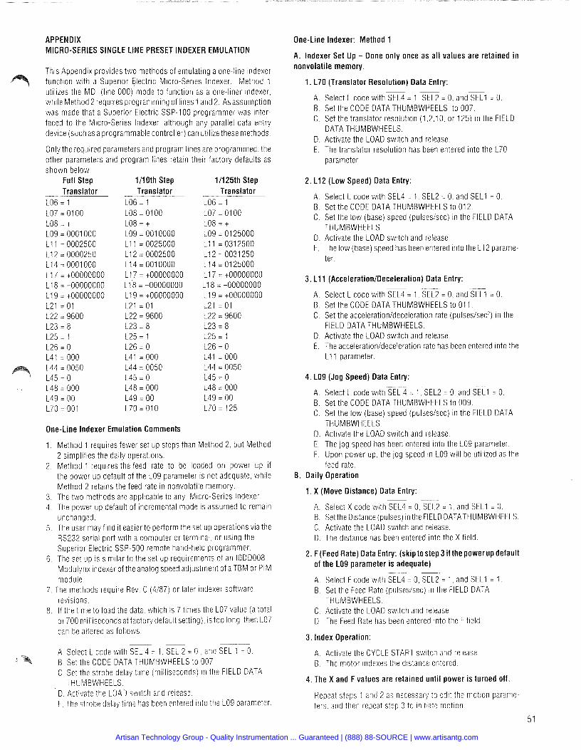
APPENDIX MICRO-SERIES SINGLE LINE PRESET INDEXER EMULATION
This Appendix provides two methods of emulating a one-line indexer function with a Superior Electric Micro-Series Indexer. Method 1 utilizes the MDI (line 000) mode to function as a one-liner indexer. while Method 2 requires programming of lines 1 and 2. Asassumption was made that a Superior Electric SSP-100 programmer was inter- faced to the Micro-Series Indexer, although any parallel data entry device (such as a programmable controller) can utilize these methods.
Only the required parameters and program lines are programmed: the other parameters and program lines retain their factory defaults as shown below:
Full Step 1110th Step 11125th Step Translator --- . - - Translator Translator
LO6 = 1 LO6 = 1 LO6 = 1
One-Line Indexer Emulation Comments
1. Method 1 requires fewer set up steps than Method 2. but Method 2 simplifies the daily operations.
2. Method 1 requires the feed rate to be loaded on power up if the power up default of the LO9 parameter is not adequate, while Method 2 retains the feed rate in nonvolatile memory.
3. The two methods are applicable to any Micro-Series lndexer. 4. The power up default of incremental mode is assumed to remain
unchanged. 5, The user may find it easierto perform the set up operations via the
RS232 serial port with a computer or terminal. or using the Superior Electric SSP-500 remote hand-held programmer.
6. The set up is similar to the set up requirements of an IODD008 Modulynx indexer of the analog speed adjustment of a TBM or PIM module.
7, The methods require Rev. C (4187) or later indexer software revisions.
8, If the time to load the data. which is 7 times the LO7 value (a total or 700 milliseconds at factory default setting). is too long, then LO7 can be altered as follows:
- - --
A Select L code with SEL 4 = 1 SEL 2 = 0 and SEL 1 = 0 I B Set the CODE DATA THUMBWHEELS to 007
C Set the strobe delay time (m~lliseconds) in the FlELD DATA THUMBWHEELS
D Act~vate the LOAD switch and release E The strobe delay time has been entered into the LO9 parameter
One-Line Indexer: Method 1
A. Indexer Set Up - Done only once as a l l values are retained in nonvolatile memory.
1. L70 (Translator Resolution) Data Entry: - -
A. Select L code with SEL4 = 1, SEL2 = 0. and%? = 0. B. Set the CODE DATA THUMBWHEELS to 007. C. Set the translator resolution (1.2,lO. or 125) in the FIELD
DATA THUMBWHEELS. D. Activate the LOAD switch and release. E. The translator resolution has been entered into the 170
parameter.
2. L12 (Low Speed) Data Entry:
A Select L code with S E L ~ = 1 SEL2 = 0 and = 0 B Set the CODE DATA THUMBWHEELS to 012 C Set the low (base) speed (pulseslsec) in the FIELD DATA
THUMBWHEELS D Activate the LOAD switch and release E The low (base) speed has been entered into the 112 parame-
ter
3. L11 (Acceleration/Deceleration) Data Entry: - -
A. Select L code with SEL4 = 1. SEL2 = 0, and S E L ~ = 0. B. Set the CODE DATA THUMBWHEELS to 01 1 6 . Set the accelerationldeceleration rate (pulses/sec2) in the
FIELD DATA THUMBWHEELS. D. Activate the LOAD switch and release. E. The accelerationldeceleration rate has been entered into the
L11 parameter.
4. LO9 (Jog Speed) Data Entry: . . -. .. . -
A. Select L code with SEL 4 = I, SEL2 = 0, a n d ? ~ ~ l = 0. B. Set the CODE DATA THUMBWHEELS to 009. C. Set the low (base) speed (pulses/sec) rn the FIELD DATA
THUMBWHEELS. D. Activate the LOAD switch and release. E. The jog speed has been entered into the LO9 parameter. F. Upon power up, the jog speed in LO9 will be utilized as the
feed rate. 8. Daily Operation
1. X (Move Distance) Data Entry: - -
A Select X code with SEL4 = 0 SEL2 = 1 and SK = 0 B Set the Distance (pulses) in the FlELD DATATHUMBWHEELS C Activate the LOAD swrtch and release D The distance has been entered into the X field
2. F(Feed Rate) Data Entry: (skip tostep 3 if the power up default of the LO9 parameter is adequate)
--
A Select F code with SEL4 = 0 K 2 = 1 and SF = 1 B Set the Feed Rate (pulseslsec) in the FIELD DATA
THUMBWHEELS C Activate the LOAD switch and release D The Feed Rate has been entered into the F field
3. Index Operation:
A. Activate the CYCLE START switch and release B. The motor indexes the distance entered.
4. The X and F values are retained unti l power is turned off
Repeat steps 1 and 2 as necessary to edit the motron parame- ters and then repeat step 3 to initiate motion
Artisan Technology Group - Quality Instrumentation ... Guaranteed | (888) 88-SOURCE | www.artisantg.com

One-Line lndexer: Method 2 8. Enter G36 ( X code Strobe) on line number 001:
A. lndexer Set Up - Done only once as all values are retained in nonvolatile memory.
1 . L70 (Translator Resolution) Data Entry:
A Select L code with s== 1 s== 0 and = 0 B Set the CODE DATA THUMBWHEELS to 070 C Set the translator resolution (1 2 10 or 125) in the FIELD
DATA THUMBWHEELS D Act~vate the LOAD swltch and release E The translator resolution has been entered into the 170
parameter
2. L12 (Low Speed) Data Entry: ---
A. Select L code with SEL4 = 1 . SEL2 = 0, a n d m = 0. B. Set the CODE DATA THUMBWHEELS to 012. C. Set the low (base) speed (pulsesisec) in the FIELD DATA
THUMBWHEELS. D. Activate the LOAD switch and release. E. The low (base) speed has been entered into the L12 parame-
ter.
3. L11 (Acceleration/Deceleration) Data Entry: -
A. Select L code with SEL4 = 1. SEL2 = 0, and SE = 0. B. Set the CODE DATA THUMBWHEELS to 01 1 C. Set the accelerationldeceleration rate (pulseslseci) in the
FIELD DATA THUMBWHEELS. D. Activate the LOAD swrtch and release. E. The acceleration/deceleration rate has been entered into the
L1 1 parameter.
4. LO9 (Jog Speed) Data Entry: (skip to step 5 if not utilizing jog function)
-- - A. Select L code with SEL4 = 1 , SEL2 = 0. and = 0. B. Set the CODE DATA THUMBWHEELS to 009. C. Set the low (base) speed (pulseslsec) ~n the FIELD DATA
THUMBWHEELS. D. Activate the LOAD switch and release. E. The low (base) speed had been entered into the L12 parame-
ter. 5. LO6 (Program Execution Mode) Data Entry:
A. Select L code w ~ t h SEL4 = 1, SEL2 = 0, and SEL 1 = 0. B. Set the CODE DATA THUMBWHEELS to 006. C. Set FIELD DATA THUMBWHEELS to 2. D. Activate the LOAD switch and release. E. The auto execution mode has been entered into the LO6
parameter.
6. L41 (Autostart Line Number) Data Entry:
A. Select L code w t h SEL4 = 1, SEL2 = 0, and KT = 0. B. Set the CODE DATA THUMBWHEELS to 041 C. Set FIELD DATA THUMBWHEELS t o 1 D Activate the LOAD switch and release. E. The autostar? line number has been entered ~ n t o the 141
parameter.
7. Select line number 001: -- --
A Select N code with ~x4 = 0 SEL2 = 0 and ~ E L I = 0 B Set the CODE DATA THUMBWHEELS to 001 C Activate the LOAD switch and release D NO01 hds been selected
-- -.
A. Select G code with SEL4 = 0 , SEL2 = 0. a n d m = 1 B. Set the CODE DATA THUMBWHEELS to 036. C. Activate the LOAD switch and release. D. G36 has been entered into the program.
9. F (Feed Rate) Data Entry: - --
A. Select F code w ~ t h SEL4 = 0. SEL2 = 1, and = l . B. Set the Feed Rate (pulseslsec) in the FIELD DATA
THUMBWHEELS. C. Activate the LOAD switch and release. D. The Feed Rate has been entered into line number 1's Ffield
10. Select Line Number 002: -
A. Select N code w ~ t h SEL4 = 0, SEL2 = 0, a n d ~ ~ i = 0 6. Set the CODE DATA THUMBWHEELS to 002. C. Activate the LOAD switch and release. D. NO02 has been selected.
11. Enter G30 (Program End) on line number 002: .. -
A. Select G code with SEL4 = 0, SEL2 = 0, a n d m = 1 B. Set the CODE DATA THUMBWHEELS to 030. C. Activate the LOAD switch and release. D. G30 has been entered into the program on line number 2
8. Daily Operation
1 . Index Operation:
A. Setthe Distance (pulses) in the FIELD DATATHUMBWHEELS. B. Activate the CYCLE START switch and release. C. The motor indexes the distance entered.
2. Repeat step 1 as necessary.
Artisan Technology Group - Quality Instrumentation ... Guaranteed | (888) 88-SOURCE | www.artisantg.com
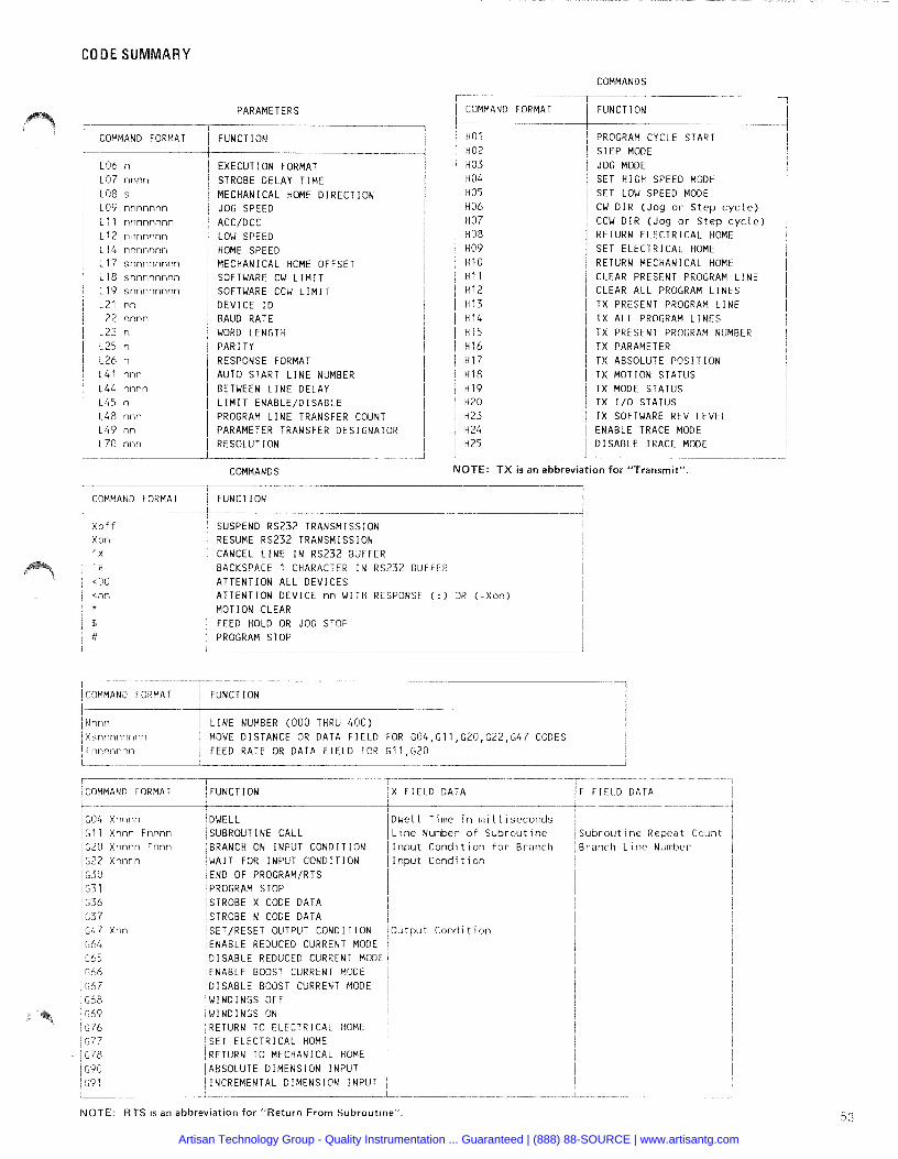
CODE SUMMARY
COMMAND FORMAT
L O 6 n L O 7 nnnn L O 8 s L O 9 nnnnnnn L l l nnnnnnnn L 1 2 nlmnnnn L 1 4 nnnnnnn L 1 7 s n n n n n n n n 1 1 8 s n n n n n n n n 1 1 9 s n n n n n n n n L 2 1 nn L 2 2 nnnn L 2 3 n
1 2 5 n 1 2 6 n 1 4 1 nnn 1 4 4 nnnn L 4 5 n
L 4 8 nnn L 4 9 nn L 7 0 nnn
PARAMETERS - .-
F U N C T I O N - .-
E X E C U T I O N FORMAT STROBE D E L A Y T I M E M E C H A N I C A L HOME D I R E C T I O N JOG SPEED ACC/DCC LOW SPEED HOME SPEED M E C H A N I C A L HOME O F F S E T SOFTWARE CW L I M I T SOFTWARE CCW L I M I T D E V I C E I D BAUD R A T E WORD LENGTH P A R I T Y RESPONSE FORMAT AUTO S T A R T L I N E NUMBER BETWEEN L I N E D E L A Y L I M I T E N A B L E / D I S A B L E PROGRAM L I N E TRANSFER COUNT PARAMETER TRANSFER D E S I G N A T O R R E S O L U T I O N
COMMANDS
COMMAND FORMAT
X o f f X o n 'X
F U N C T I O N
SUSPEND R S 2 3 2 T R A N S M I S S I O N RESUME R S 2 3 2 T R A N S M I S S I O N CANCEL L I N E I N R S 2 3 2 BUFFER
COMMAND FORMAT
COMMANDS -- -- - -
F U N C T I O N - - -
PROGRAM CYCLE START S T E P MODE JOG MODE S E T H I G H SPEED MODE S E T LOW SPEED MODE C U D I R ( J o g o r S t e p c y c l e ) CCW D I R ( J o g o r S t e p c y c l e ) RETURN E L E C T R I C A L HOME S E T E L E C T R I C A L HOME RETURN M E C H A N I C A L HOME CLEAR PRESENT PROGRAM L I N E CLEAR A L L PROGRAM L I N E S T X PRESENT PROGRAM L I N E T X A L L PROGRAM L I N E S T X PRESENT PROGRAM NUMBER T X PARAMETER T X ABSOLUTE P O S I T I O N T X M O T I O N S T A T U S T X MODE S T A T U S T X 1 / 0 S T A T U S T X SOFTWARE REV L E V E L E N A B L E TRACE MODE D I S A B L E TRACE MODE
NOTE: TX is an abbreviation for "Transmit".
BACKSPACE 1 CHARACTER I N R S 2 3 2 BUFFER A T T E N T I O N A L L D E V I C E S A T T E N T I O N D E V I C E nn W I T H RESPONSE ( : ) OR ( = X o n ) M O T I O N CLEAR FEED HOLD OR JOG STOP PROGRAM STOP
I ICOMMAND FORMAT 1 F U N C T I O N
I I N n n n X s n n n n n n n n I F n n n n n n n
/ L I N E NUMBER ( 0 0 0 THRU 4 0 0 1 / MOVE D I S T A N C E OR D A T A F I E L D FOR G O 4 , G l l , G 2 D , G 2 2 , G 4 7 CODES
1 FEED R A T E OR D A T A F I E L D FOR G 1 1 ,G2O
1 COMMAND FORMAT / F U N C T I O N / X F I E L D D A T A
G O 4 X n n n n I G l l X n n n F n n n n G 2 0 X n n n n F n n n G 2 2 X n n n n I G 3 0 l G 3 1 I G 3 6 G 3 7 G 4 7 X n n C 6 4
I G65 G 6 6 G 6 7 C 6 8
D w e l l T i m e i n m i l l i s e c o n d s L i n e N u m b e r o f S u b r o u t i n e
/ B R A N C H ON I N P U T C O N D I T I O N /Input C o n d i t i o n f o r B r a n c h / W A I T F O R I N P U T C O N D I T I O N I l n p u t C o n d i t i o n END O F PROGRAM/RTS PROGRAM STOP 1
/STROBE x CODE D A T A I / S T R O B E N CODE D A T A I / SET/RESET OUTPUT C O N D I T I O N /output C o n d i t i o n /ENABLE REDUCED CURRENT MODE 1 I D ISABLE REDUCED CURRENT MODE 1 I E N A B L E BOOST CURRENT MODE I D I S A B L E BOOST CURRENT MODE / W I N D I N G S O F F !
/WINDINGS ON I R E T U R N T O E L E C T R I C A L HOME 1 ! S E T E L E C T R I C A L HOME i /RETURN TO M E C H A N I C A L HOME I / A B S O L U T E D I M E N S I O N I N P U T 1 / INCREMENTAL D I M E N S I O N I N P U T /
F I E L D D A T A
; u b r o u t i n e R e p e a t C o u n t j r a n c h L i n e N u m b e r
NOTE: RTS is an abbreviation for "Return From Subroutine".
Artisan Technology Group - Quality Instrumentation ... Guaranteed | (888) 88-SOURCE | www.artisantg.com
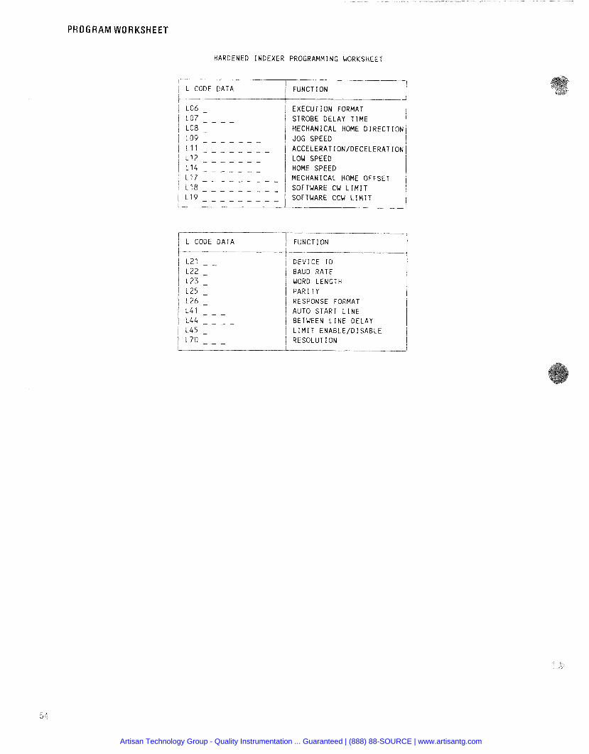
PROGRAM WORKSHEET
HARD ENED INDEXER
L CODE DATA
L CODE DATA
ROGRAMMING WORKSHEET
FUNCTION
I EXECUTION FORMAT STROBE DELAY T I M E
I MECHANICAL HOME D I R E C T I O N JOG SPEED I ACCELERATION/DECELERATION/ LOW SPEED HOME SPEED 1 MECHANICAL HOME OFFSET I SOFTWARE CW L I M I T SOFTWARE CCW L I M I T
I I
FUNCTION -
D E V I C E I D BAUD RATE WORD LENGTH PAR I TY RESPONSE FORMAT AUTO START L I N E BETWEEN L I N E DELAY L I M I T E N A B L E / D I S A B L E RESOLUTION
Artisan Technology Group - Quality Instrumentation ... Guaranteed | (888) 88-SOURCE | www.artisantg.com
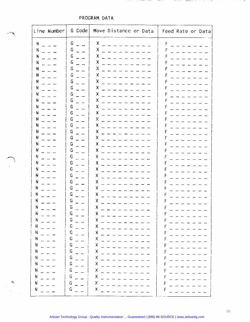
PROGRAM D A T A
L i n e Number G Code ove D is tance o r Data Feed Rate o r Dat;
Artisan Technology Group - Quality Instrumentation ... Guaranteed | (888) 88-SOURCE | www.artisantg.com
Superlor Electrlc products are available nationwide In addition, Superior Electric sales engineers and manu- through an extensive authorized distributor network. facturers' representatives are conveniently located to These distributors offer literature. technlcal assistance provide prompt attention to customers' needs. Call the and a wide range of models off the shelf for fastest nearest office listed for ordering and application informa- , possible delivery. tion or for the address of the closest authorized distributor.
383 Middle Street Br~stol. CT 061 01 Tel: (203) 582-9561 TWX: 71 0-454-0682 - FAX: 203-589-21 36 Customer Serivce: 1-800-227-6470 Product Application: 1-800-227-6471 FAX: 1-800-766-6366 Product Literature Request: 1-800-766-71 71
Superior Electric Nederland B.V. Koperwerf 33 2544 EM The Hague, Netherlands Tel: 31 70 3 679590 TELEX: 31 436 Supe nl FAX: 01 I 31 70 3 296274
WARRANTY AND LIMITATION OF LIABILITY
Superior Electric (the Company ) Bristol Connecticut warrants to the first end user purchaser (the purchaser ) of equipment manufactured by the Company that such equipment if new unused and in original unopened cartons at the time of purchase will be free from defects in material and workmanship under normal use and service for a period of one year from date of shipment from the Company s factory or a warehouse of the Company in the event that the equipment is purchased from the Company or for a period of one year from the date of shipment from the business establishment of an authorized distributor of the Company in the event that the equipment is purchased from an authorized distributor
THE COMPANY'S OBLIGATION UNDER THIS WARRANTY SHALL BE STRICTLY AND EXCLUSIVELY LIMITED TO REPAIRING OR REPLACING, AT THE FACTORY OR A SERVICE CENTER OF THE COMPANY, ANY SUCH EQUIPMENT OR PARTS THEREOF WHICH AN AUTHORIZED REPRESENTATIVE OF THE COMPANY FINDS TO BE DEFECTIVE IN MATERIAL OR WORKMANSHIP UNDER NORMAL USE AND SERVICE WITHIN SUCH PERIOD OF ONE YEAR. THE COMPANY RESERVES THE RIGHTTO SATISFY SUCH OBLIGATION IN FULL BY REFUNDING THE FULL PURCHASE PRICE OF ANY SUCH DEFECTIVE EQUIPMENT. This warranty does not apply to any equipment which has been tampered with or altered in any way which has been improperly installed or which has been subject to misuse neglect or accident
THE FOREGOING WARRANTY IS IN LIEU OF ANY OTHER WARRANTIES, EXPRESS OR IMPLIED, INCLUDING, WITHOUT LIMITATION, ANY IMPLIED WARRANTY OF MERCHANTABILITY OR FITNESS FOR A PARTICULAR PURPOSE, and of any other obligations or liabilities 1
on the part of the Company and no person is authorized to assume for the Company any other liability with respect to equipment manufactured by the Company The Company shall have no liab~lity with respect to equipment not of its manufacture THE COMPANY SHALL HAVE NO LIABILITY WHATSOEVER IN ANY EVENT FOR PAYMENTOF ANY INCIDENTAL OR CONSEQUENTIAL DAMAGES, INCLUDING, WITHOUT LIMITATION, DAMAGES FOR INJURY TO ANY PERSON OR PROPERTY.
Written authorization to return any equipment or parts thereof must be obtained from the Company The Company shall not be responsible tor any transportation charges
IF FOR ANY REASON ANY OF THE FOREGOING PROVISIONS SHALL BE INEFFECTIVE, THE COMPANY'S LIABILITY FOR DAMAGES ARISING OUT OF ITS MANUFACTURE OR SALE OF EQUIPMENT, OR USE THEREOF, WHETHER SUCH LIABILITY IS BASED ON WARRANTY, CONTRACT, NEGLIGENCE, STRICT LIABILITY IN TORT OR OTHERWISE, SHALL NOT IN ANY EVENT EXCEED THE FULL PURCHASE PRICE OF SUCH EQUIPMENT.
Any action against the Company based upon any liability or obligation arising hereunder or under any law applicable to the sale of equipment or the use thereof must be commenced within one year after the cause of such action arises
These products are sold subject to the standard Limitation of Liability and'or Warranty of The Superior Electric Company The American Superior Electric Company Lid or Superior Electric Nederland B V
The right to make engineering refinements on all products is reserved Dimensions and other details are subject to change
TEL: (203) 582-9561 TELEX: 96-2446 : 7 10-454-0682 Cable Address: SUPELEC FAX: (203) 589-2 136
A213710 0 2 5 . R E V . D Printed in U S
Artisan Technology Group - Quality Instrumentation ... Guaranteed | (888) 88-SOURCE | www.artisantg.com