Embed Size (px)
Citation preview

The OHIO DEPARTMENTof TRANSPORTATION


January 1999 i
PrefacePurpose
Many manuals, policies, guides, standards, etc.,have been published regarding pavement designand rehabilitation. Many of these have beenwritten using wide ranges of designrecommendations (minimums and maximums)since the contents were intended to applynationally. Furthermore, the Ohio Department ofTransportation’s pavement design andrehabilitation procedures have been scatteredamong many different publications, poorlydocumented or in some cases existed only in theminds of a select few engineers. The purpose ofthis manual is to bring all the information togetherin one document, reduce the selection of designvariables to those most appropriate for the State ofOhio, to document Ohio’s interpretation of variouspolicies and to include design criteria which may beunique to Ohio.
Application
The pavement engineering concepts describedherein are intended for use with all new orreconstruction projects, major and minorrehabilitation projects, and all preventivemaintenance projects, which are under thejurisdiction of the Ohio Department ofTransportation (ODOT). The informationcontained in this manual has been taken from andbased on the results of the AASHO Road Test, theAASHTO Guide for Design of PavementStructures, Federal Highway Administration(FHWA) guidelines and technical advisories,various training course manuals, as well as fromthe experience of the authors. In addition, theapplication of other studies, experiences, andengineering judgments have been included to fitOhio's conditions.
The pavement design procedures relate theperformance of a pavement to its structural designand the loading applied to the pavement. Failuremechanisms derived from poor mix design, poormaterial quality, or poor construction practices arenot addressed in this manual.
This manual is neither a textbook nor a substitutefor engineering knowledge, experience orjudgement. It is intended to provide uniformprocedures for implementing design decisions,assure quality and continuity in design of
pavements in Ohio, and assure compliance withFederal criteria. The recommendations given areintended to improve pavement performance.
Consideration must be given to design standardsadopted by city, county, or other local governmentswhen designing pavements under their jurisdiction.
Distribution
This manual is intended primarily for ODOTpersonnel who have received training from theOffice of Materials Management. It is madeavailable to cities, counties, consultants, etc., touse at their own risk.
Preparation
The Pavement Design and Rehabilitation Manualhas been developed by the Office of MaterialsManagement. Errors or omissions should bereported to the Pavement Design Section of theOffice of Materials Management, Ohio Departmentof Transportation, 1600 West Broad Street, Room2033, Columbus, Ohio 43223.
Format and Revisions
Updating the manual is intended to be acontinuous process and revisions will be issuedperiodically.
Although pages are individually numbered withineach section, new pages may be added andidentified with letter suffixes after the page number.Figures do not have page numbers but arenumbered to coincide with the section number inthe text. Figures are located at the end of eachsection and are printed on colored paper for easyreference.
Each page has the latest revision date shown inthe lower left hand corner. Revisions will be issuedas needed by the Office of Materials Management.The looseleaf format of the manual makesupdating a quick and simple task. Users areencouraged to keep their manuals up to date.
Manuals may be ordered by contacting the OhioDepartment of Transportation, Office of Contracts,P.O. Box 899, Columbus, Ohio 43216-0899, (614)466-3778, 466-3200.

January 1999 ii
Pavement Design Approval and ResponsibilityAll pavement design buildups pertaining to roadways designated as Interstates, US Routes, NationalHighway System (NHS) routes, and State Routes or otherwise under the jurisdiction of the OhioDepartment of Transportation must be approved by the Ohio Department of Transportation prior toincorporation into a set of construction plans. Those Agencies, Municipalities, or Consultants seekingpavement design buildup or approval from the Ohio Department of Transportation should make therequest through the appropriate ODOT District Office.
A formal request for pavement design buildup or approval should include the following:
• Plan and profile sheets indicating the existing and proposed profile.
• Typical section templates indicating the pavement and shoulder widths, lane lines andpavement/shoulder cross slopes.
• All required soils information, including the soil profile and soils reports.
• Traffic data, certified by the Office of Technical Services, indicating the average daily traffic (ADT)and percentage trucks in the 24-hour count for both the current year and design year.

January 1999 iii
Glossary of TermsCalifornia Bearing Ratio (CBR) - A value obtainedby standardized soil testing procedures comparingthe load required to penetrate the soil to a standardunit load.
Composite Modulus of Subgrade Reaction (Kc) - Avalue used in rigid pavement design determined bydividing the load on a subgrade by the deflection,corrected for the effect of a base.
Concrete Elastic Modulus (Ec) - A measure of therigidity of a pavement slab and its ability todistribute loads.
Contraction Joint - A joint at the ends of a rigidpavement slab to control the location of transversecracks.
Design Serviceability Loss ()PSI) - The change inthe serviceability index of a pavement from thetime it is constructed to the end of its design life.
Design Structural Number (SN) - A regressioncoefficient derived from an analysis of traffic, soilconditions and environment and which may beconverted to thickness of flexible pavement layersusing coefficients related to the type of materialbeing used in each layer of the pavement structure.
Discount Rate - An economic factor to account forthe effects of interest and inflation.
Drainage Coefficient - A factor used to modifystructural layer coefficients in flexible pavements,or stress in rigid pavements, as a function of howwell the pavement structure can handle the effectof water infiltration.
Effective Modulus of Subgrade Reaction (K) - TheComposite Modulus of Subgrade Reactionmodified by Loss of Support.
Equivalent Single Axle Load (ESAL) - Truck trafficloading expressed as the number of equivalent18,000 lb (80 kN) single axle loads.
Expansion Joint - A transverse joint located toprovide for the expansion of a rigid slab in thelongitudinal direction without damage to itself oradjacent slabs. Generally placed near bridges.
Functional Characteristics - Qualities of apavement such as surface smoothness, skidresistance, and non-load related distresses suchas block cracking, and oxidation of asphaltpavement surfaces.
Functional Classification - The grouping ofhighways by the character of service they provide.
Group Index - A number derived from thegradation, liquid limit and plasticity index of a soil.
Life-Cycle Cost Analysis - A process for evaluatingthe economic worth of a pavement segment byanalyzing initial costs and discounted future costsover a defined period.
Liquid Limit - The moisture content at which a soilflows like a viscous liquid.
Load Transfer Coefficient (J) - A factor used inrigid pavement design to account for the ability ofa concrete pavement to distribute load acrossjoints and cracks.
Longitudinal Joint - A pavement joint, in thedirection of traffic flow, used to control longitudinalcracking on a rigid pavement or the joint formedbetween adjacent passes of a paver on a flexiblepavement.
Loss of Support (Ls) - A factor included in thedesign of rigid pavement to account for thepotential loss of support arising from base erosionand/or differential vertical soil movements.
Major Rehabilitation - Work performed on apavement intended to restore structural integrityand functional characteristics.
Mean Concrete Modulus of Rupture (S’c) - Theflexural strength of concrete derived from a beamtest with third point loading.
Minor Rehabilitation - Work performed on apavement intended to restore functionalcharacteristics and protect the structural integrity.
Multi-Lane Pavements - Pavements with four ormore lanes. Continuous two-way left turn lanesare considered lanes in this definition.

January 1999 iv
Overall Standard Deviation - A statistical measureto account for the error in the prediction of trafficand pavement performance.
Pavement Condition Rating (PCR) - A numericalrating of pavement distresses on a 0 to 100 scalebased on visual inspection. A PCR of 100 signifiesa perfect pavement with no distress.
Pavement Edge (Edge of Pavement) - Theintersection of the mainline pavement and thetreated shoulder or turf shoulder.
Plastic Limit - The minimum moisture content atwhich the soil acts as a plastic solid.
Present Serviceability Index (PSI) - A numericalindex which correlates roughness measurementson a scale of 0 to 5. A PSI of 5 indicates anexceptionally smooth pavement.
Pressure Relief Joint - Similar to Expansion Jointbut placed exclusively near bridges to preventdamage to the bridge.
Preventive Maintenance - Work performed on astructurally sound pavement, generally in the formof a surface treatment, intended to preserve thepavement, retard future deterioration, and maintainor improve the functional condition withoutsubstantially increasing the structural capacity.
Reliability (R) - A statistical measure of theprobability that a section of pavement will meet orexceed the predicted performance.
Structural Deduct - A part of the PavementCondition Rating indicating distresses which maybe related to the structural integrity of thepavement.
Structural Integrity - The ability of a pavement tocarry anticipated loading.
Structural Layer Coefficient - A measure of therelative ability of a material to function as astructural component of a flexible pavementstructure and used to convert a design structuralnumber to actual thickness.
Subbase Elastic Modulus - A measure of the abilityof a subbase to carry a load.
Subgrade Resilient Modulus (Mr) - A measurementof the stress dependency of a subgrade soil,determined by the LTPP P46 test procedure.
Terminal Serviceability Index (Pt) - Theserviceability index assumed at the end of thepavement design life.
Transverse Joint - A pavement joint perpendicularto the centerline alignment of the pavement,designed to control cracking, provide for loadtransfer, and allow for the contraction andexpansion of the pavement.

June 1999 v
Reference DocumentsCircular Number A-94 (Office of Management andBudget - 1992), Appendix C (OMB - CurrentRevision)
Construction and Material Specifications (ODOT -Current Edition)
Guide for Design of Pavement Structures(AASHTO - 1993)
Highway Engineering Handbook (McGraw-Hill -1996)
Location and Design Manual, Volume Two -Drainage Design (ODOT - Current Revision)
Location and Design Manual, Volume Three -Highway Plans (ODOT - Current Revision)
Location and Design Manual, Volume Three -Highway Plans, Sample Plan Sheets (ODOT -Current Revisions)
Manual of Operation and Use of Dynaflect forPavement Evaluation (ODOT - 1983)
Manual of Procedures for Concrete (ODOT -Current Revision)
Manual of Procedures for Earthwork Construction(ODOT - Current Revision)
Manual of Procedures for Flexible PavementConstruction (ODOT - Current Revision)
Manual of Procedures for Rigid PavementPractices (ODOT - Current Revision)
Pavement Rehabilitation Design Training Course,Participants Manual (ODOT - 1997)
Principles of Pavement Design (Wiley-Interscience- 1975)
Specifications for Subsurface Investigations(ODOT - Current Revision)
Standard Construction Drawings (Location &Design, ODOT - Current Revisions)
Verification of the ODOT Overlay DesignProcedure (ODOT - 1996)
Pavement Condition Rating System (ODOT -1999)

June 1999 vi
AcknowledgmentsPrinciple Writers:
Aric A. Morse, P.E.Pavement Engineering CoordinatorODOT Office of Materials Management
David W. Miller, P.E.Assistant Pavement EngineerODOT Office of Materials Management
The authors wish to thank the following people for their assistance in writing, reviewing, editing, printing,and distributing this Manual. Without their efforts, this Manual would not have been possible.
William L. Christensen, P.E., ODOT Office of Highway ManagementThomas B. Culp, P.E., ODOT District ThreeKaren S. Eitel, ODOT Office of Materials ManagementDean A. Focke, P.E., ODOT Office of PlanningDonald H. Glosser, P.E., American Concrete Pavement AssociationRoger L. Green, P.E., ODOT Office of Materials ManagementKeith D. Herbold, P.E., FHWA Midwest Resource CenterRobert T. McQuiston, P.E., FHWA Ohio DivisionKimberly M. Mondora, P.E., ODOT District FourDavid B. Powers, P.E., ODOT Office of Materials ManagementRussell L. Slonecker, P.E., ODOT District OneClifford Ursich, P.E., Flexible Pavements, Inc.Debbie L. Moreno and everyone at the ODOT Print Shop

Table of Contents
100 Pavement Management 1-1100.1 Introduction . . . . . . . . . . . . . . . . . . . . . . . . . . . . . . . . . . . . . . . . . . . . . . . . . . 1-1100.2 Pavement Condition Rating . . . . . . . . . . . . . . . . . . . . . . . . . . . . . . . . . . . . . . 1-1100.3 Present Serviceability Index . . . . . . . . . . . . . . . . . . . . . . . . . . . . . . . . . . . . . . 1-1
101 Project Level Pavement Management and Analysis 1-1101.1 PCR Historical Trends . . . . . . . . . . . . . . . . . . . . . . . . . . . . . . . . . . . . . . . . . . 1-1101.2 PCR Performance Equations . . . . . . . . . . . . . . . . . . . . . . . . . . . . . . . . . . . . . 1-1101.3 Pavement Modeling . . . . . . . . . . . . . . . . . . . . . . . . . . . . . . . . . . . . . . . . . . . . 1-2
200 Pavement Design Concepts 2-1200.1 Introduction . . . . . . . . . . . . . . . . . . . . . . . . . . . . . . . . . . . . . . . . . . . . . . . . . . 2-1
201 Serviceability 2-1201.1 Initial Serviceability . . . . . . . . . . . . . . . . . . . . . . . . . . . . . . . . . . . . . . . . . . . . . 2-1201.2 Terminal Serviceability . . . . . . . . . . . . . . . . . . . . . . . . . . . . . . . . . . . . . . . . . . 2-1201.3 Design Serviceability Loss . . . . . . . . . . . . . . . . . . . . . . . . . . . . . . . . . . . . . . . 2-1
202 Traffic Considerations 2-1202.1 Traffic Loading . . . . . . . . . . . . . . . . . . . . . . . . . . . . . . . . . . . . . . . . . . . . . . . . 2-1202.2 Calculation of ESAL’s . . . . . . . . . . . . . . . . . . . . . . . . . . . . . . . . . . . . . . . . . . 2-2202.3 ESAL99 . . . . . . . . . . . . . . . . . . . . . . . . . . . . . . . . . . . . . . . . . . . . . . . . . . . . . 2-2
203 Subgrade Soil Characterization 2-2203.1 Subgrade Resilient Modulus . . . . . . . . . . . . . . . . . . . . . . . . . . . . . . . . . . . . . 2-3203.2 California Bearing Ratio . . . . . . . . . . . . . . . . . . . . . . . . . . . . . . . . . . . . . . . . . 2-3203.3 Group Index . . . . . . . . . . . . . . . . . . . . . . . . . . . . . . . . . . . . . . . . . . . . . . . . . . 2-3203.4 Soil Profile Analysis . . . . . . . . . . . . . . . . . . . . . . . . . . . . . . . . . . . . . . . . . . . . 2-4
204 Reliability 2-4204.1 Overall Standard Deviation . . . . . . . . . . . . . . . . . . . . . . . . . . . . . . . . . . . . . . 2-5
205 Subsurface Pavement Drainage 2-5205.1 Types of Drainage Systems . . . . . . . . . . . . . . . . . . . . . . . . . . . . . . . . . . . . . . 2-5205.2 AASHTO Drainage Coefficient . . . . . . . . . . . . . . . . . . . . . . . . . . . . . . . . . . . 2-6
300 Rigid Pavement Design Procedures & Considerations 3-1300.1 Introduction . . . . . . . . . . . . . . . . . . . . . . . . . . . . . . . . . . . . . . . . . . . . . . . . . . 3-1
301 Design Parameters 3-1301.1 Modulus of Rupture . . . . . . . . . . . . . . . . . . . . . . . . . . . . . . . . . . . . . . . . . . . . 3-1301.2 Modulus of Elasticity . . . . . . . . . . . . . . . . . . . . . . . . . . . . . . . . . . . . . . . . . . . 3-1301.3 Load Transfer Coefficient . . . . . . . . . . . . . . . . . . . . . . . . . . . . . . . . . . . . . . . 3-1301.4 Composite Modulus of Subgrade Reaction . . . . . . . . . . . . . . . . . . . . . . . . . . 3-1301.5 Loss of Support . . . . . . . . . . . . . . . . . . . . . . . . . . . . . . . . . . . . . . . . . . . . . . . 3-2301.6 Effective Modulus of Subgrade Reaction . . . . . . . . . . . . . . . . . . . . . . . . . . . . 3-2

302 Thickness Determination 3-2302.1 Ramps and Interchanges . . . . . . . . . . . . . . . . . . . . . . . . . . . . . . . . . . . . . . . 3-2
303 Jointing and Shoulder Considerations 3-2303.1 Transverse Joints . . . . . . . . . . . . . . . . . . . . . . . . . . . . . . . . . . . . . . . . . . . . . 3-2303.2 Expansion Joints . . . . . . . . . . . . . . . . . . . . . . . . . . . . . . . . . . . . . . . . . . . . . 3-2303.3 Longitudinal Joints . . . . . . . . . . . . . . . . . . . . . . . . . . . . . . . . . . . . . . . . . . . . 3-3303.4 Shoulder Considerations . . . . . . . . . . . . . . . . . . . . . . . . . . . . . . . . . . . . . . . 3-3303.5 Edge Course Design . . . . . . . . . . . . . . . . . . . . . . . . . . . . . . . . . . . . . . . . . . 3-3303.6 Intersection Jointing Details . . . . . . . . . . . . . . . . . . . . . . . . . . . . . . . . . . . . . 3-3
304 Smoothness Specifications 3-3
305 Composite Pavement 3-3305.1 Composite Pavement Design . . . . . . . . . . . . . . . . . . . . . . . . . . . . . . . . . . . . 3-4305.2 Composite Pavement Typical Section Design. . . . . . . . . . . . . . . . . . . . . . . 3-4305.3 Composite Pavement Smoothness Specifications . . . . . . . . . . . . . . . . . . . 3-4
400 Flexible Pavement Design Procedures & Considerations 4-1400.1 Introduction . . . . . . . . . . . . . . . . . . . . . . . . . . . . . . . . . . . . . . . . . . . . . . . . . . 4-1
401 Design Parameters 4-1
402 Structural Number Determination 4-1402.1 Ramps and Interchanges . . . . . . . . . . . . . . . . . . . . . . . . . . . . . . . . . . . . . . . 4-1
403 Typical Section and Buildup Considerations 4-1403.1 Typical Section Design . . . . . . . . . . . . . . . . . . . . . . . . . . . . . . . . . . . . . . . . . 4-1403.2 Shoulder Buildups . . . . . . . . . . . . . . . . . . . . . . . . . . . . . . . . . . . . . . . . . . . . 4-2403.3 Edge Course Design . . . . . . . . . . . . . . . . . . . . . . . . . . . . . . . . . . . . . . . . . . 4-2403.4 Paved Shoulder Edge Course Design . . . . . . . . . . . . . . . . . . . . . . . . . . . . . 4-2
404 Lift Thickness and Specification Guidelines 4-2404.1 All Item 446 & 448 Type 1 and Type 2 Courses . . . . . . . . . . . . . . . . . . . . . . 4-3404.2 Superpave Specifications . . . . . . . . . . . . . . . . . . . . . . . . . . . . . . . . . . . . . . . 4-3404.3 Item 446 & 448 Asphalt Concrete Surface Course, Type 1, PG64-22 . . . . . 4-3404.4 Items 446 and 448 Asphalt Concrete Surface Course, Type 1H . . . . . . . . . 4-3404.5 Item 446 Asphalt Concrete Intermediate Course, Type 1, PG64-22 . . . . . . 4-4404.6 Item 446 Asphalt Concrete Intermediate Course, Type 2, PG64-28 & PG64-22
. . . . . . . . . . . . . . . . . . . . . . . . . . . . . . . . . . . . . . . . . . . . . . . . . . . . . . . . . 4-4404.7 Item 448 Asphalt Concrete Intermediate Course, Type 1, PG64-28 & PG64-22
. . . . . . . . . . . . . . . . . . . . . . . . . . . . . . . . . . . . . . . . . . . . . . . . . . . . . . . . . 4-4404.8 Item 448 Asphalt Concrete Intermediate Course, Type 2, PG64-28 & PG64-22
. . . . . . . . . . . . . . . . . . . . . . . . . . . . . . . . . . . . . . . . . . . . . . . . . . . . . . . . . 4-5404.9 Item 301 Bituminous Aggregate Base, PG64-22 . . . . . . . . . . . . . . . . . . . . . 4-5404.10 Item 302 Bituminous Aggregate Base, PG64-22 . . . . . . . . . . . . . . . . . . . . 4-5404.11 Item 407 Tack Coat . . . . . . . . . . . . . . . . . . . . . . . . . . . . . . . . . . . . . . . . . . 4-6404.12 Item 408 Prime Coat . . . . . . . . . . . . . . . . . . . . . . . . . . . . . . . . . . . . . . . . . 4-6
405 Smoothness Specifications 4-6

500 Pavement Design Procedures for Minor Rehabilitation 5-1500.1 Introduction . . . . . . . . . . . . . . . . . . . . . . . . . . . . . . . . . . . . . . . . . . . . . . . . . . 5-1
501 Deflection Measuring Equipment 5-1501.1 Dynaflect . . . . . . . . . . . . . . . . . . . . . . . . . . . . . . . . . . . . . . . . . . . . . . . . . . . . 5-1501.2 Falling Weight Deflectometer . . . . . . . . . . . . . . . . . . . . . . . . . . . . . . . . . . . . 5-1
502 Deflection Testing and Analysis 5-1502.1 General . . . . . . . . . . . . . . . . . . . . . . . . . . . . . . . . . . . . . . . . . . . . . . . . . . . . . 5-1502.2 Analysis . . . . . . . . . . . . . . . . . . . . . . . . . . . . . . . . . . . . . . . . . . . . . . . . . . . . . 5-2502.3 Factors Affecting Deflections . . . . . . . . . . . . . . . . . . . . . . . . . . . . . . . . . . . . . 5-2
503 Overlay Design Procedure 5-3503.1 Introduction . . . . . . . . . . . . . . . . . . . . . . . . . . . . . . . . . . . . . . . . . . . . . . . . . . 5-3503.2 Rigid Pavements . . . . . . . . . . . . . . . . . . . . . . . . . . . . . . . . . . . . . . . . . . . . . . 5-3503.3 Flexible Pavements . . . . . . . . . . . . . . . . . . . . . . . . . . . . . . . . . . . . . . . . . . . . 5-4503.4 Composite Pavements . . . . . . . . . . . . . . . . . . . . . . . . . . . . . . . . . . . . . . . . . . 5-4
504 Minor Rehabilitation Strategies 5-5504.1 Asphalt Considerations . . . . . . . . . . . . . . . . . . . . . . . . . . . . . . . . . . . . . . . . . 5-5504.2 Milling . . . . . . . . . . . . . . . . . . . . . . . . . . . . . . . . . . . . . . . . . . . . . . . . . . . . . . . 5-5504.3 Pavement Repair . . . . . . . . . . . . . . . . . . . . . . . . . . . . . . . . . . . . . . . . . . . . . . 5-5504.4 Reflective Crack Control . . . . . . . . . . . . . . . . . . . . . . . . . . . . . . . . . . . . . . . . 5-7504.5 Concrete Pavement Restoration . . . . . . . . . . . . . . . . . . . . . . . . . . . . . . . . . . 5-7504.6 Geometric Issues . . . . . . . . . . . . . . . . . . . . . . . . . . . . . . . . . . . . . . . . . . . . . . 5-7504.7 Pavement Widening . . . . . . . . . . . . . . . . . . . . . . . . . . . . . . . . . . . . . . . . . . . 5-7
600 Major Rehabilitation Design 6-1600.1 Introduction . . . . . . . . . . . . . . . . . . . . . . . . . . . . . . . . . . . . . . . . . . . . . . . . . . 6-1600.2 Subgrade Determination . . . . . . . . . . . . . . . . . . . . . . . . . . . . . . . . . . . . . . . . 6-1
601 Unbonded Concrete Overlay 6-1
602 Fractured Slab Techniques 6-2602.1 Crack & Seat . . . . . . . . . . . . . . . . . . . . . . . . . . . . . . . . . . . . . . . . . . . . . . . . . 6-2602.2 Rubblize & Roll . . . . . . . . . . . . . . . . . . . . . . . . . . . . . . . . . . . . . . . . . . . . . . . 6-2
603 Whitetopping 6-3
700 Life-Cycle Cost Analysis 7-1700.1 Introduction . . . . . . . . . . . . . . . . . . . . . . . . . . . . . . . . . . . . . . . . . . . . . . . . . . 7-1
701 Initial Construction 7-1
702 Future Maintenance 7-2702.1 Introduction . . . . . . . . . . . . . . . . . . . . . . . . . . . . . . . . . . . . . . . . . . . . . . . . . . 7-2702.2 Maintenance Schedules . . . . . . . . . . . . . . . . . . . . . . . . . . . . . . . . . . . . . . . . 7-2
703 Total Cost 7-4703.1 Discounting . . . . . . . . . . . . . . . . . . . . . . . . . . . . . . . . . . . . . . . . . . . . . . . . . . 7-4

704 Lane Closure Days 7-4
705 Results Presentation 7-4
Pavement Design and Selection Process Appendix A
Pavement Guidelines for Treatment of High Stress Locations Appendix B
Simplified Pavement Designs for Short Projects Appendix C
ODOT’s PCR Manual Appendix D
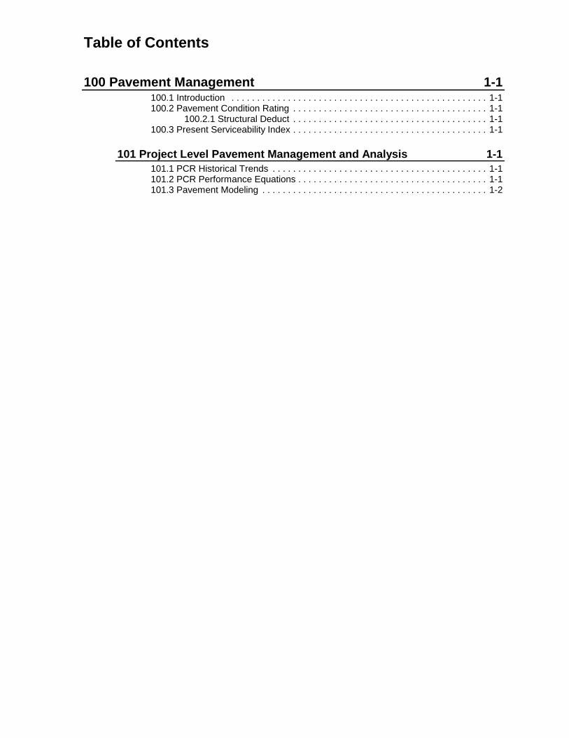
Table of Contents
100 Pavement Management 1-1100.1 Introduction . . . . . . . . . . . . . . . . . . . . . . . . . . . . . . . . . . . . . . . . . . . . . . . . . . 1-1100.2 Pavement Condition Rating . . . . . . . . . . . . . . . . . . . . . . . . . . . . . . . . . . . . . . 1-1
100.2.1 Structural Deduct . . . . . . . . . . . . . . . . . . . . . . . . . . . . . . . . . . . . . . 1-1100.3 Present Serviceability Index . . . . . . . . . . . . . . . . . . . . . . . . . . . . . . . . . . . . . . 1-1
101 Project Level Pavement Management and Analysis 1-1101.1 PCR Historical Trends . . . . . . . . . . . . . . . . . . . . . . . . . . . . . . . . . . . . . . . . . . 1-1101.2 PCR Performance Equations . . . . . . . . . . . . . . . . . . . . . . . . . . . . . . . . . . . . . 1-1101.3 Pavement Modeling . . . . . . . . . . . . . . . . . . . . . . . . . . . . . . . . . . . . . . . . . . . . 1-2

January 1999 1-1
100 Pavement Management100.1 Introduction
The movement of people and goods throughoutthe state, as well as interstate, is primarilydependent upon the transportation network ofpavements managed by the Ohio Department ofTransportation (ODOT). The management of thisvast network is aided by ODOT’s PavementManagement System (PMS). ODOT’s PMS is asystematic approach that provides various reportsregarding the condition of each and everypavement section, as well as the system as awhole. For the purpose of standard pavementanalyses, the Pavement Condition Rating (PCR),Present Serviceability Index (PSI), and theStructural Deduct (SD) are all contained within thestandard PMS report outputs. Standard PMSreports are available for download. For detailedinformation regarding the PMS, contact the Officeof Technical Services.
100.2 Pavement Condition Rating
Pavement Condition Rating (PCR) is based on avisual inspection of the condition of the pavementby trained raters. The rater catalogs pavementdistresses in terms of severity and extent, assignsa deduct to each distress, and subtracts the sum ofthe deducts from 100. A pavement in perfectcondition receives a PCR of 100. PCR data iscollected annually for all divided and undividedstate highways with exception of those locatedinside corporate limits of municipalities. ThisManual includes ODOT’s PCR Manual in AppendixD.
100.2.1 Structural Deduct
Structural Deduct (SD) is contained within thePCR, but indicates those distresses which may berelated to the structural integrity of the pavement.A structural deduct of 25 or more indicates thepavement section should be considered for majorrehabilitation.
100.3 Present Serviceability Index
Present Serviceability Index (PSI) is a measure ofpavement surface roughness or riding comfort. Itis measured on a scale between 0 and 5, with 5being a perfectly smooth ride. PSI data is collectedannually for all divided and undivided statehighways with exception of those located insidecorporate limits of municipalities. More detailconcerning the concept of Serviceability ispresented in Section 201.
101 Project Level PavementManagement and AnalysisDetermination of the most cost effective time andtreatment for the rehabilitation of a pavement is themost difficult problem a pavement engineerencounters. The solution to this problem is furthercomplicated by funding uncertainties andshortages, as well as difficulties with planpreparation or detail design work which can createa delay of project delivery. The most cost effectivetreatment is dependent on pavement condition andthe most cost effective time to treat a pavementdepends upon the type of treatment involved. Forexample, a major rehabilitation should be delayedas long as possible in order to get the remaininglife out of the existing pavement, as this type oftreatment relies little on the existing structure.However, a preventive maintenance applicationmust be done when the pavement is in goodstructural condition. In order to address anypavement section with some type of maintenanceor rehabilitation treatment it is necessary to be ableto predict pavement deterioration over time.Without knowing the condition of the pavement atthe time of construction, it is impossible to prepareconstruction plans and fiscal budgets that willreflect the needs of the pavement.
101.1 PCR Historical Trends
The most basic way of predicting pavementcondition is by using the past to predict the future.The use of regression analysis is well suited forthis purpose, however, it must be understood thatpast performance does not necessarily indicate thefuture. This type of analysis is easily performed byusing PCR data as far back as the last actionperformed on a particular pavement section, andincorporating this data into a simple spreadsheetand performing a regression analysis.
101.2 PCR Performance Equations
With the aid of research contracts, ODOT hasdeveloped models concerning pavementdeterioration. The equations presented are afunction of pavement type and the last activityperformed on the pavement. For more informationon the activities described, refer to Sections 500and 600. These models should not be usedwithout intuitive reasoning, as they were developedwith data from the entire state network and may notbe representative of every pavement section.Figure 101-1 lists all available pavementperformance models.

Pavement Management
January 1999 1-2
101.3 Pavement Modeling
The ability to predict the condition of a pavement isnot a perfected technique at this time. However,using the equations in Figure 101-1 as well asdoing a regression analysis on the PCR data fromthe actual pavement and plotting this informationdoes provide the pavement designer with someinsight into performance trends. Figure 101-2 is anexample of such a plot.
Figure 101-2 displays a fictitious project which wasrubblized and rolled in 1990. Provided in this figureis the actual PCR data, a regression of the actual
PCR data, along with the appropriate pavementdeterioration model for the fractured slabtechnique. All of this information is then graphedversus the year the data points apply. Thisexample illustrates the use of this graphicalrepresentation as a tool which can be used topredict the condition of the pavement in the future.It can be seen that the predicted PCR of thefictitious pavement will likely be in the upper-50's inthe year 2002 and may be a candidate for majorrehabilitation if something is not planned for theyear 2002 or earlier.

100 Pavement Management
List of FiguresFigure Date Subject
101-1 January 1999 Pavement Deterioration Models
101-2 January 1999 Regression Analysis Spreadsheet

Pavement Deterioration Models101-1
January 1999
Reference Section101
RIGID PAVEMENT
Minor Rehabilitation:All Overlays with and without Repairs PCR = 96.0 - 3.7(AGE)CPR PCR = 96.2 - 7.0 (AGE)
New Rigid Pavement & Unbonded Concrete Overlay PCR = 99.1 - 0.9 (AGE)
FLEXIBLE PAVEMENT
Minor RehabilitationNon-Structural Overlay with Minimal Repairs PCR = 98.1 - 3.3 (AGE)Non-Structural Overlay with Repairs PCR = 98.6 - 3.8 (AGE)Structural Overlay with Minimal Repairs PCR = 98.3 - 3.3 (AGE)Generic Minor Rehabilitation (all of the above) PCR = 98.0 - 3.3 (AGE)
Major RehabilitationFractured Slab Technique PCR = 98.0 - 3.4 (AGE)New Flexible Pavement PCR = 99.5 - 2.0 (AGE)
COMPOSITE PAVEMENT
Minor RehabilitationNon-Structural Overlay with Minimal Repairs PCR = 96.1 - 4.0 (AGE)Non-Structural Overlay with Repairs PCR = 96.1 - 3.8 (AGE)Structural Overlay with Minimal Repairs PCR = 96.1 - 4.3 (AGE)Structural Overlay with Repairs PCR = 96.1 - 3.3 (AGE)
Generic Minor Rehabilitation (all of the above) PCR = 96.0 - 3.7 (AGE)
New Composite Pavement PCR = 99.6 - 3.3 (AGE)

50
60
70
80
90
100
PCR
1990 1992 1994 1996 1998 2000 2002Year
PCR Regression Model
Regression Analysis Spreadsheet101-2
January 1999
Reference Section101
Year PCR Regression ModelRegression Output
1990 100 97 981991 93 94 95 Constant 6332.0891992 88 90 91 Std Err of Est 2.4637051993 86 87 88 R Squared 0.9327231994 84 84 84 No. of Observations 91995 83 81 81 Degrees of Freedom 71996 77 78 781997 72 75 74 X Coefficient(s) -3.133331998 75 72 71 Std Err of Coef. 0.3180631999 69 672000 65 642001 62 612002 59 57
Pavement Modeling Plot
Table of Contents
200 Pavement Design Concepts 2-1200.1 Introduction . . . . . . . . . . . . . . . . . . . . . . . . . . . . . . . . . . . . . . . . . . . . . . . . . . 2-1
201 Serviceability 2-1201.1 Initial Serviceability . . . . . . . . . . . . . . . . . . . . . . . . . . . . . . . . . . . . . . . . . . . . . 2-1201.2 Terminal Serviceability . . . . . . . . . . . . . . . . . . . . . . . . . . . . . . . . . . . . . . . . . . 2-1201.3 Design Serviceability Loss . . . . . . . . . . . . . . . . . . . . . . . . . . . . . . . . . . . . . . . 2-1
202 Traffic Considerations 2-1202.1 Traffic Loading . . . . . . . . . . . . . . . . . . . . . . . . . . . . . . . . . . . . . . . . . . . . . . . . 2-1
202.1.1 Conversion Factors . . . . . . . . . . . . . . . . . . . . . . . . . . . . . . . . . . . . 2-1202.1.2 Traffic Data . . . . . . . . . . . . . . . . . . . . . . . . . . . . . . . . . . . . . . . . . . 2-2202.1.3 B:C Ratios . . . . . . . . . . . . . . . . . . . . . . . . . . . . . . . . . . . . . . . . . . . 2-2202.1.4 Design Lane Factors . . . . . . . . . . . . . . . . . . . . . . . . . . . . . . . . . . . 2-2
202.2 Calculation of ESAL’s . . . . . . . . . . . . . . . . . . . . . . . . . . . . . . . . . . . . . . . . . . 2-2202.3 ESAL99 . . . . . . . . . . . . . . . . . . . . . . . . . . . . . . . . . . . . . . . . . . . . . . . . . . . . . 2-2
203 Subgrade Soil Characterization 2-2203.1 Subgrade Resilient Modulus . . . . . . . . . . . . . . . . . . . . . . . . . . . . . . . . . . . . . 2-3203.2 California Bearing Ratio . . . . . . . . . . . . . . . . . . . . . . . . . . . . . . . . . . . . . . . . . 2-3203.3 Group Index . . . . . . . . . . . . . . . . . . . . . . . . . . . . . . . . . . . . . . . . . . . . . . . . . . 2-3203.4 Soil Profile Analysis . . . . . . . . . . . . . . . . . . . . . . . . . . . . . . . . . . . . . . . . . . . . 2-4
203.4.1 Unsuitable Subgrade Soil . . . . . . . . . . . . . . . . . . . . . . . . . . . . . . . 2-4203.4.2 Soil Stabilization Methods . . . . . . . . . . . . . . . . . . . . . . . . . . . . . . . 2-4
204 Reliability 2-4204.1 Overall Standard Deviation . . . . . . . . . . . . . . . . . . . . . . . . . . . . . . . . . . . . . . 2-5
205 Subsurface Pavement Drainage 2-5205.1 Types of Drainage Systems . . . . . . . . . . . . . . . . . . . . . . . . . . . . . . . . . . . . . . 2-5
205.1.1 Pipe Underdrains . . . . . . . . . . . . . . . . . . . . . . . . . . . . . . . . . . . . . . 2-5205.1.2 Prefabricated Edge Drains . . . . . . . . . . . . . . . . . . . . . . . . . . . . . . . 2-5205.1.3 Aggregate Drains . . . . . . . . . . . . . . . . . . . . . . . . . . . . . . . . . . . . . . 2-5205.1.4 Free Draining Base Options . . . . . . . . . . . . . . . . . . . . . . . . . . . . . 2-5
205.2 AASHTO Drainage Coefficient . . . . . . . . . . . . . . . . . . . . . . . . . . . . . . . . . . . 2-6

January 1999 2-1
200 Pavement Design Concepts200.1 Introduction
Perhaps the most widely used pavement designmethod used in the United States and throughoutthe world is that presented in the AASHTO Guidefor Design of Pavement Structures. A long historyof pavement studies has lead to the current (1993)edition. The ODOT method for the design ofpavement structures is almost identical to theAASHTO method, but ODOT has simplified someparts of the AASHTO Guide since it needs to applyonly to the conditions encountered in Ohio.
The AASHTO / ODOT pavement design equationshave some variables that are common to both rigidand flexible pavement, including: serviceability,traffic loading, reliability, overall standard deviation,and roadbed soil resilient modulus. The remainingvariables needed for the design of a pavementstructure are presented in the respective rigid andflexible pavement sections on design procedures.
201 ServiceabilityODOT’s Pavement Design Method (AASHTO) isdeveloped around the concept of serviceability,which serves as the pavement performanceparameter by which a pavement’s condition isvalued. Serviceability is defined as the ability of apavement to serve traffic. The PresentServiceability Rating (PSR) was developed tomeasure serviceability. PSR is a rating ofpavement ride based on a scale of 0, forimpassible, to 5, for perfect. For the developmentof the original AASHTO Pavement DesignEquation, individuals (the raters) would ride thepavements and assign a PSR value. To avoidriding and rating every pavement by all raters todetermine serviceability, a relationship betweenPSR and measurable pavement attributes hasbeen developed. This relationship is defined asthe Present Serviceability Index (PSI).
201.1 Initial Serviceability
Data obtained by the Office of Technical Services(see Section 100.3) indicates that pavementsconstructed in Ohio in the past have averaged aninitial PSI of 4.2 for rigid pavements and 4.5 forflexible pavements.
201.2 Terminal Serviceability
ODOT pavements are designed for a minimum PSI(terminal serviceability) of 2.5.
201.3 Design Serviceability Loss
The design serviceability loss is the amount ofserviceability the agency will tolerate losing beforerehabilitation. The design serviceability loss isdefined as the difference between the terminalserviceability and the initial serviceability. Figure201-1 lists the design serviceability loss.
202 Traffic ConsiderationsPerhaps the most important step in designing apavement is the estimation of the design traffic.Overestimation of the design traffic results in athicker pavement than necessary with higherassociated costs. Underestimation of traffic resultsin a thin pavement that will fail prematurely causingincreased maintenance and impact on the user.
202.1 Traffic Loading
For design purposes, all traffic is converted to atraffic load which is normalized by the concept ofan Equivalent 18,000 lb (80 kN) Single Axle Load(ESAL). The conversion of traffic to the ESAL isaccomplished with the use of axle load equivalencyfactors. Equivalency factors are a function ofpavement type and thickness, among other factors.Equivalency factors are provided in the AASHTOGuide.
202.1.1 Conversion Factors
In order to simplify the process of converting eachtruck expected on the roadway to an ESAL, ODOTuses ESAL conversion factors for the average ofgroups of trucks. The vehicles are grouped into twocategories: single or C units, and tractor-trailer orB combinations. As truck numbers and axleweights are being monitored continuously,conversion factors are calculated yearly by theOffice of Technical services for both truck types forthe different functional classifications beingmonitored. The conversion factors printed in thismanual are based on a rolling ten-year average ofthe data provided by the Office of TechnicalServices and are updated as necessary whensignificant changes in the ten-year rolling averageare found. Refer to Figure 202-1 for ODOT’s mostcurrent ESAL Conversion Factors.

Pavement Design Concepts
January 1999 2-2
202.1.2 Traffic Data
Basic traffic data should be forecasted and certifiedby the Office of Technical Services or the District.This data must include the Average Daily Traffic(ADT) and the 24-hour truck percentage for thecurrent year as well as the design year, twelve ortwenty years hence. This data is typically found inthe Design Designation for the project. It isimportant to insure the truck percentage is a 24-hour percentage and not a peak hour percentage.
202.1.3 B:C Ratios
Truck counts can be broken down into two trucktype categories. The larger trucks such as 4 ormore axle single units and semi-tractor trailers areclassified as B type trucks. Smaller trucks such asthree axle single units and buses are classified asC type trucks. The Office of Technical Servicescollects this data on a sampling basis and reportsthe data using statewide averages by functionalclassification. B:C Ratios are presented in Figure202-1. These ratios should be used only wherecurrent project counts are not available. Actual B& C counts are always more accurate than the B:Cratio provided in Figure 202-1.
202.1.4 Design Lane Factors
Average Daily Traffic (ADT) counts always includeall lanes and both directions of travel. In order todesign the required pavement thickness, the ADTneeds to be adjusted to represent the loading onthe design lane. This is done by applying theDirectional Distribution, which defines the loadingin each direction of travel, and the Lane Factor,which distributes the trucks into the different lanes.The Design Designation generally indicates adirectional distribution other than 50%, howeverthis distribution represents the peak-hour volumeand is used for geometric design purposes.Unless the designer has specific, credibleinformation indicating unequal loading on the twodirections, and this imbalance is expected tocontinue throughout the design life of thepavement, it should be assumed that eachdirection will have equal loading over the design lifeand a directional distribution of 50% used. If thedesigner is certain loading is unequal, a directionaldistribution other than 50% may be used butcaution is advised as this can have significantimpact on the on the pavement thickness required.Refer to Figure 202-1 for ODOT’s most currentLane Factors.
202.2 Calculation of ESAL’s
The calculation of ESAL’s is very simple once allthe data is available. The following equations areused. All percentages are to be expressed as adecimal.
ADT * %T24 * D * LF * %B * CF = B ESAL’sADT * %T24 * D * LF * %C * CF = C ESAL’s
B ESAL’s + C ESAL’s = Total ESAL’s
Where:ADT = Average Daily Traffic%T24 = 24-hour truck percentage of ADTD = Directional DistributionLF = Lane factor%B, C = % B or C trucks of the total trucksCF = Appropriate truck conversion
factor
Examples of the calculation of design ESAL’s areprovided in Figures 302-1 and 402-1.
202.3 ESAL99
Another method for the calculation of ESAL’s isavailable for locations where historical traffic datais available. This method takes into accountgrowth rates in numbers of trucks as well growthrates in the conversion factors associated with thetrucks. The method relies on the practice offorecasting the future based on trends of the past.However, trends of the past may not be anindication of future performance.
For more information regarding this methodcontact the Office of Materials Management,Pavements Section.
2 0 3 S u b g r a d e S o i lCharacterizationThe subgrade is the foundation for all pavements.Trying to characterize the strength of thisfoundation for a particular pavement is a verydifficult task because of the variability found innature and during construction. The AASHTOpavement design equations used by ODOT requirethe characterization of the strength of the subgradeby using the roadbed soil resilient modulus. Fordesign of pavement, subgrade soil type isdetermined directly from soil tests made inconjunction with the soil profile or bridge foundationinvestigations. In Ohio, soils are classified based

Pavement Design Concepts
January 1999 2-3
on gradation and Atterburg Limits. Figure 203-1represents the classification system for Ohio soils.
On all new location projects it is imperative that acomplete soils investigation and soil profile(subsurface investigation) be performed prior topavement design. Pavement design for pavementreplacement projects and pavement wideningprojects can be performed using a historicalsubsurface investigation, where it exists, however,it is recommended to perform an additionalsubsurface investigation to design for weaksubgrade conditions and to validate the pavementdesign calculations. The need for soils informationregarding major rehabilitation projects is covered inSection 600.2. In order to insure sufficientinformation will be obtained from a soilsinvestigation, refer to ODOT’s “Specifications forSubsurface Investigations”.
General information about soil types can be foundin the Soil Survey books which are published forevery county in Ohio. Additional information onsoils and proper construction practices can befound in the Manual of Procedures for EarthworkConstruction put out by the Office of HighwayManagement.
203.1 Subgrade Resilient Modulus
The subgrade resilient modulus is a measure ofthe ability of a soil to resist permanent deformationunder repeated loading. Many soils are stressdependent. As the stress level increases, thesesoils will behave in a nonlinear fashion. Fine-grained soils tend to be stress-softening, whereasgranular soils tend to be stress-hardening. Thelaboratory test (LTPP P 46) is designed todetermine the strain due to a repeated load(deviator stress) which duplicates the effects ofloads passing over a section of pavement.
Based on limited research and several currentpublications, ODOT has adopted a standardrelationship between Modulus of Resilience andthe California Bearing Ratio (CBR).
Equation 203.1: Mr = 1200 * CBR
203.2 California Bearing Ratio
The California Bearing Ratio (CBR) is mostcommonly obtained by doing a laboratorypenetration test of a soaked sample of soil. Theload required to produce a penetration at each 0.1inch depth in the soaked sample is divided by a
standard which has been developed for crushedstone.
CBR CRUSHED STONE STANDARD
PENETRATION LOAD
0.1 INCH 1000 PSI
0.2 INCH 1500 PSI
0.3 INCH 1900 PSI
0.4 INCH 2300 PSI
0.5 INCH 2600 PSI
203.3 Group Index
The Group Index (GI) is a value which representsa soil type and attempts to characterize the soilsstrength. GI is a function of a soil’s AtterbergLimits and gradation. Group Index is defined bythe following equation:
Equation 203.3:
GI = %P - 35* [0.2 + 0.005* (L.L. - 40)] + 0.01*[%P - 15]*[P.I. - 10]
Where:
%P = The percentage passing the #200sieve.
L.L. = The Liquid Limit which is thewater content at which a soil flowslike a viscous liquid.
P.I. = The Plasticity Index which is thenumerical difference of the liquidand plastic limits, and indicatesthe range of water contentthrough which the soil flows.
The nomographs shown in Figure 203-2 solveEquation 203.3.
In order to reduce the amount of laboratory testingrequired to characterize the soil strength, ODOTdeveloped a relationship between CBR and GroupIndex. This relationship was developed in the early1960's by testing thousands of soil samples.Figure 203-3 provides a correlation chart to convertthe Group Index to the CBR.

Pavement Design Concepts
January 1999 2-4
203.4 Soil Profile Analysis
The soil profile is one of the most useful tools forany geotechnical analysis. This manual onlyconsiders the usefulness of the soil profile as itapplies to pavement design. Using the soil profile,the Atterberg Limits and GI can be obtaineddirectly for most samples. Where complete soilclassifications are not provided, refer to Figure203-1 for estimates of GI. The most appropriateGI to use for pavement design is determined byusing engineering judgment. Consideration shouldbe given only to the soil located within the top 3feet (1m) of proposed subgrade. An average soiltype is to be used for pavement design. ODOT’sPavement Design Procedure uses a statisticalreliability factor (see Section 204) to account forthe variability found in the subgrade strength. Themost common error found when reviewingpavement designs is the use of a CBR value whichis too conservative, in other words using the worstsoil rather than the average. Determination of thesoil type and strength parameters for borrow usedin fill situations should be considered. Anassumption must be made as to where the borrowwill come from. Usually it is assumed that theborrow will come from somewhere nearby and willlikely be the same soil type. Evaluation should alsoinclude consideration of the cut material to be usedfor fill.
203.4.1 Unsuitable Subgrade Soil
Frost susceptible silts are never to be used withinone meter of proposed subgrade elevation. Thesesoils are classified as A-4b and should be set upfor undercut and replacement with suitablesubgrade materials. It is important to rememberthat these soils will not be part of the subgrade andshould not be included in the average soil strengthvalue used for design.
Weak-wet soils with blow counts of only one or twoare not suitable for subgrade under pavement, andshould be removed and replaced with suitablematerial, or stabilized with lime or cement.
203.4.2 Soil Stabilization Methods
ODOT CMS Item 206 Lime Soil StabilizedSubgrade is available for use on subgrade whichhas high clay content. Although it is commonlyassumed that the stabilization of the soil results inhigher subgrade strength, ODOT’s current designmethods do not provide for reduced pavementsection as a result of modified subgrade.
ODOT CMS 712.09 provides requirements forType D Geotextile Fabric. This fabric can be usedat the bottom of undercuts as a separator betweenunsuitable clay or silt and the proposed granularembankment or aggregate base. The separatorkeeps the migration of clay and silt from closing thevoids in the layers above and causing settlementand/or pumping.
Geotextile fabrics are often recommended to beused as a construction aid to speed construction,but should not be used to thin the requiredpavement thickness.
Geotechnical recommendations regarding properembankment construction, including subgradetreatment, may be requested from the Office ofMaterials Management, Geotechnical DesignSection.
204 ReliabilityAASHTO defines Reliability as “the probability thatthe load applications a pavement can withstand inreaching a specified minimum serviceability level isnot exceeded by the number of load applicationsthat are actually applied to the pavement”.Technically, reliability is a statistical tool used inpavement design which assumes a standardnormal distribution exists for all pavement designparameters and allows the designer to account fordeviation from the average, equally for allparameters. Reliability parameters can be thoughtof as safety factors. Figure 201-1 lists theReliability Factors to be used in pavement designfor various classifications of highways.

Pavement Design Concepts
January 1999 2-5
204.1 Overall Standard Deviation
The overall standard deviation (variance) is ameasure of the spread of the probability distributionfor ESAL’s vs. Serviceability, considering all theparameters used to design a pavement. Figure201-1 lists the Overall Standard Deviation to beused in pavement design.
205 Subsurface PavementDrainageSubsurface pavement drainage is required on allprojects. Lack of adequate pavement drainage isthe primary cause of distress in many pavements.Excess moisture in the base and subgradereduces the amount of stress the subgrade cantolerate without strain. Strain in the subgradetransfers the stress into the upper pavement layerswhich induces deformation, and ultimately distress.Trapped moisture in flexible pavement systemsleads to stripping, raveling, debonding, and rutting.Excess moisture in rigid pavement systems leadsto pumping, faulting, cracking, and joint failure.
Several approaches are available to keeppavement systems drained. Joint and cracksealing can be done to reduce the infiltration ofwater. Strategic placement of underdrains andedgedrains is used to capture the water quicklyand outlet it. The use of free draining base ispromoted to capture all pavement drainage.
205.1 Types of Drainage Systems
There are four means of draining the pavementsubsurface - pipe underdrains, prefabricated edgedrains, aggregate drains and free draining basesystems.
205.1.1 Pipe Underdrains
Pipe underdrains must be used for all Interstate,freeways, expressways, and multi-lane facilities.Pipe underdrains are generally used with pavedshoulders and curbed pavements. Refer toFigures 1009-1 to 1009-5 of the Location & DesignManual, Volume 2 - Drainage Design; and Location& Design Manual, Volume 3 - Highway Plans,Sample Plan Sheets for locations of pipeunderdrains with the various pavement - shouldertreatments. Special consideration must be given tothe design of pipe underdrains for free drainingbase options. Refer to Section 205.1.4.
205.1.2 Prefabricated Edge Drains
Prefabricated edge drains are located at the edgeof existing concrete pavement on resurfacingprojects where the existing pavement and pavedshoulders are being retained. If existing pavedshoulders are being replaced, a 4 inch (~100 mm)shallow pipe underdrain at the edge of pavementshould be used in lieu of the prefabricated edgedrain. On resurfacing projects, where edge drainsalready exist, existing outlets should be inspectedand replaced where they no longer function.
205.1.3 Aggregate Drains
Aggregate drains are used with bituminous surfacetreated shoulders, aggregate shoulders, and forspot improvements. Aggregate drains are used onlower volume roadways with bituminous stabilizedor turf shoulders, or any pavement system whichdoes not have pipe underdrains or prefabricatededgedrains. Drains should be located at 50-foot(~15 m) intervals on each side of the pavementand staggered so each drain is 25 feet (~7.5 m)from the adjacent drain on the opposite side. Ifused on rigid pavements, the drains should belocated to match up to the end of a transversejoint. For superelevated pavements, spacingshould be at 25 feet (~7.5 m) and drains should belocated on the low side only. Aggregate drainsshould be physically cut into the edge of thepavement - shoulder system, preferably theaggregate base. Refer to Figures 1009-8 and1009-9 of the Location & Design Manual, Volume2 - Drainage Design; and Location & DesignManual, Volume 3 - Highway Plans, Sample PlanSheets for details depicting aggregate drains withthe various pavement - shoulder treatments.
205.1.4 Free Draining Base Options
It is generally accepted that water is one of themost significant causes of pavement deterioration.A free draining base (FDB) placed within apavement system is highly effective at removingwater which enters the pavement system from thesurface after a rain shower or other precipitation.Free draining base systems should be consideredfor all multi-lane facilities. Free draining bases maynot be feasible in urban settings where utilities arenumerous because the ability to properly constructand maintain a free draining base is greatlyreduced where manholes, catch basins, waterlines, and other utilities are present.
Where a free draining base is specified it shouldnot extend into the ramps or crossroads.
Pavement Design Concepts
January 1999 2-6
There are two basic types of free draining basesfor use under pavements: stabilized and non-stabilized. Stabilized free draining base consists ofa blend of #57 and #8 aggregate with a Portlandcement or asphalt cement binding agent. CementTreated Free Draining Base is Item 306 andAsphalt Treated Free Draining Base is Item855.The stabilized bases provide a very stableconstruction platform and allow the contractor touse the base as a haul road for short periods oftime. The contractor must accept all risk for thepotential damage to the base. Non-stabilized freedraining bases, Item 307, have three differentgradations, none of which are stable enough to beused for a haul road but which have ample stabilityfor paving. All but one of the free draining basesare 4 inches (~100 mm) thick, the exception beingthe non-stabilized Type ‘CE’, which is 6 inches(~150 mm) thick.
The choice of free draining base type is dependentupon pavement type, constructability andpreference. There are concerns regarding the useof a stabilized free draining bases because of therelatively short time they have been used and thelack of performance data which is available. Infact, there are not yet any available studies whichhave been done nationwide which indicate the costeffectiveness of using any FDB. Ohio hasdocumented the non-stabilized free draining base-Type ‘NJ’ may be inducing premature midpanelcracking under rigid pavements and its use underrigid pavements is not recommended. There areseparate concerns regarding the use of a stabilizedfree draining base, due to the potential for longterm erosion of the binding agent.
All free draining base courses must include a 6inch (~150 mm) layer of Item 304 Aggregate Baseplaced below the free draining base. This layercontributes to the structural capacity of thepavement, provides a stable platform for pavingand acts as a filter to prevent the migration of thesubgrade into the free draining base, potentially
closing the voids and clogging the drains. Item 408Prime Coat is required on the surface of theaggregate base to prevent the fines contained inthe aggregate base from washing into the drainagesystem. The prime coat should be applied at 0.4gallons per square yard (~1.8 liters per squaremeter) on top of the aggregate base, everywhereexcept above the underdrain trenches.
Two separate drainage systems are used withpavements which have a free draining base. Oneset of underdrains is provided exclusively for thefree draining base, and a second set is providedexclusively for the subgrade. Since the FDB layercollects and drains water between the load carryinglayers, sound and committed maintenance isessential in order to provide the performancebenefits of this base course. Free draining basesshould not be constructed if they are not going tobe maintained throughout the life of the pavement.Maintenance consists mainly of making sure theoutlets are functioning properly and are notclogged with debris or blocked in some way.Consideration should be given to marking outletswith sign and post for projects with free drainingbase. For examples of typical sections depictingFDB refer to Figures 1009-6 and 1009-7 of theLocation & Design Manual, Volume 2 - DrainageDesign.
205.2 AASHTO Drainage Coefficient
The AASHTO pavement design equations attemptto consider the effects of drainage on pavementperformance. The nomographs used in thismanual are reprinted from AASHTO and allow forthe use of the drainage coefficient for rigidpavement design. The flexible design method inthis manual does not include the drainage factor.For ODOT pavement design the DrainageCoefficient shall always be 1.0 for design of bothrigid and flexible pavements.

200 Pavement Design Concepts
List of FiguresFigure Date Subject
201-1 January 1999 Serviceability & Reliability
202-1 January 1999 Traffic Factors
203-1 January 1999 Legend and Classification of Soils
203-2 January 1999 Group Index Charts
203-3 January 1999 Subgrade Resilient Modulus

Serviceability & Reliability201-1
January 1999
Reference Section201 & 204
SERVICEABILITY FACTORSRIGID / COMPOSITE FLEXIBLE
Initial Serviceability 4.2 4.5
Terminal Serviceability 2.5 2.5
Design Serviceability Loss 1.7 2.0
RELIABILITY LEVELS (%)FUNCTIONAL CLASSIFICATION URBAN RURAL
Interstate and Freeway 95 90
Principle Arterial, Minor Arterial 90 85
Collectors 90 85
Local 80 80
OVERALL STANDARD DEVIATION
Flexible Pavement 0.49
Rigid Pavement 0.39

Traffic Factors202-1
January 1999
Reference Section202
RATIO OF B:C COMMERCIAL VEHICLESFUNCTIONAL CLASSIFICATION B:C RATIO
Rural Interstate 5:1
Rural Principal Arterial 4:1
All Other Rural 2:1
Urban Interstate, Urban Freeway & Expressway, & Urban Principal Arterial 2:1
All Other Urban 1:2
ESAL CONVERSION FACTORS
FUNCTIONAL CLASSIFICATIONRIGID FLEXIBLE
B C B C
Rural Interstate 1.84 0.53 1.18 0.40
Rural Principal Arterial 2.36 1.02 1.51 0.66
Rural Minor Arterial (All Others) 1.45 1.59 0.91 0.98
Urban Interstate 2.22 0.78 1.41 0.56
Urban Expressway & Freeway 1.35 0.65 0.78 0.48
Urban Principal Arterial (All Others) 1.60 0.71 0.94 0.43
LANE FACTORSNumber of Lanes % Trucks in Design Lane Directional Distribution (%)
2 - Lane 100 50
4 - Lane 90 50
6 (or more) - Lane 80 50

Ohio Soils Classification System203-1
January 1999
Reference Section203

Group Index Charts203-2
January 1999
Reference Section203

Subgrade Resilient Modulus203-3
January 1999
Reference Section203
Table of Contents
300 Rigid Pavement Design Procedures & Considerations 3-1300.1 Introduction . . . . . . . . . . . . . . . . . . . . . . . . . . . . . . . . . . . . . . . . . . . . . . . . . . 3-1
301 Design Parameters 3-1301.1 Modulus of Rupture . . . . . . . . . . . . . . . . . . . . . . . . . . . . . . . . . . . . . . . . . . . . 3-1301.2 Modulus of Elasticity . . . . . . . . . . . . . . . . . . . . . . . . . . . . . . . . . . . . . . . . . . . 3-1301.3 Load Transfer Coefficient . . . . . . . . . . . . . . . . . . . . . . . . . . . . . . . . . . . . . . . 3-1301.4 Composite Modulus of Subgrade Reaction . . . . . . . . . . . . . . . . . . . . . . . . . . 3-1301.5 Loss of Support . . . . . . . . . . . . . . . . . . . . . . . . . . . . . . . . . . . . . . . . . . . . . . . 3-2301.6 Effective Modulus of Subgrade Reaction . . . . . . . . . . . . . . . . . . . . . . . . . . . . 3-2
302 Thickness Determination 3-2302.1 Ramps and Interchanges . . . . . . . . . . . . . . . . . . . . . . . . . . . . . . . . . . . . . . . . 3-2
303 Jointing and Shoulder Considerations 3-2303.1 Transverse Joints . . . . . . . . . . . . . . . . . . . . . . . . . . . . . . . . . . . . . . . . . . . . . 3-2303.2 Expansion Joints . . . . . . . . . . . . . . . . . . . . . . . . . . . . . . . . . . . . . . . . . . . . . . 3-2303.3 Longitudinal Joints . . . . . . . . . . . . . . . . . . . . . . . . . . . . . . . . . . . . . . . . . . . . . 3-3303.4 Shoulder Considerations . . . . . . . . . . . . . . . . . . . . . . . . . . . . . . . . . . . . . . . . 3-3303.5 Edge Course Design . . . . . . . . . . . . . . . . . . . . . . . . . . . . . . . . . . . . . . . . . . . 3-3303.6 Intersection Jointing Details . . . . . . . . . . . . . . . . . . . . . . . . . . . . . . . . . . . . . . 3-3
304 Smoothness Specifications 3-3
305 Composite Pavement 3-3305.1 Composite Pavement Design . . . . . . . . . . . . . . . . . . . . . . . . . . . . . . . . . . . . 3-4305.2 Composite Pavement Typical Section Design. . . . . . . . . . . . . . . . . . . . . . . . 3-4305.3 Composite Pavement Smoothness Specifications . . . . . . . . . . . . . . . . . . . . 3-4

January 1999 3-1
300 Rigid Pavement Design Procedures & Considerations300.1 Introduction
Rigid pavements can be constructed withcontraction joints, expansion joints, doweled joints,no joints, temperature steel , continuous reinforcingsteel, or no steel. Regardless of the type of rigidpavement to be constructed, the ODOT/AASHTOmethod of pavement design calculates the samerequired thickness. The required thickness is afunction of loading, material properties includingsubgrade, and the type of joints, if any. Alterationsto rigid pavement material specifications, jointingconsiderations, and mesh provisions other thanthose provided in ODOT’s Construction andMaterial Specifications or ODOT’s StandardConstruction Drawings may require adjustments tothe procedures described herein.
Additional information on rigid pavement andproper construction practices can be found in theManual of Procedures for Rigid PavementPractices and the Manual of Procedures forConcrete put out by the Office of HighwayManagement
301 Design ParametersODOT’s method for the design of rigid pavementlimits the designer to prescribed input parameters.The input values prescribed are based on Ohiomaterials, and ODOT Specifications.
301.1 Modulus of Rupture
Modulus of Rupture, as determined under abreaking load, measures the flexural strength orextreme fiber stress, of the concrete slab. Thereare many ways to determine the modulus ofrupture and each way will give slightly differentresults; however, each method can be correlatedto the measure defined for use in theAASHTO/ODOT method. The modulus of ruptureas defined for ODOT’s pavement design method isthe 28 day - third point loading test as defined byASTM C 78. All rigid pavement design should usea Modulus of Rupture of 700 psi, as shown inFigure 301-1. Average values obtained throughbeam breaks performed as part of ODOTConstruction and Material Specificationrequirements should not be used directly for designpurposes, as this test is defined by ASTM C 293 asa center point loading, and are generally done asearly as 5 days.
301.2 Modulus of Elasticity
The modulus of elasticity of concrete is a functionof the strength, age, aggregate properties, cementproperties, and type and size of the specimentested as well as rate of loading during the test.Furthermore there are various methods used todetermine the modulus of elasticity. ODOT’smethod for rigid pavement thickness design is nothighly sensitive to the value used for modulus ofelasticity. Based on values obtained by recentODOT research, a Modulus of Elasticity of5,000,000 psi should be used for all rigid pavementdesign. The Modulus of Elasticity is also listed inFigure 301-1.
301.3 Load Transfer Coefficient
The load transfer coefficient (J) is a factor used inrigid pavement design to account for the ability ofa concrete pavement to transfer (distribute) loadacross discontinuities, such as joints or cracks.Load transfer devices, aggregate interlock,widened lanes, and the presence of tied concreteshoulders all have an influence on this value. Jfactors are listed in Figure 301-1.
301.4 Composite Modulus of SubgradeReaction
The Composite Modulus of Subgrade Reactionrepresents the combined effect of the subgradestrength or subgrade modulus of resilience, asdiscussed in Section 203.1, and the strength, orelastic modulus, and thickness of the subbasematerial. The pavement design process requiresthe designer to choose the subbase prior to thedetermination of the required slab thickness. Thevalues to be used for the elastic modulus of thesubbase for ODOT materials is listed in Figure301-1. Figure 301-2 is a nomograph whichdetermines the Composite Modulus of SubgradeReaction.
For uncurbed pavements carrying more than 50ESAL’s per day and for curbed pavements carryingmore than 100 ESAL’s per day, a 6 inch granularbase (Item 304) is recommended to preventpumping for concrete pavements on fine grainedsoils.
Rigid Pavement Design Procedures & Considerations
January 1999 3-2
301.5 Loss of Support
Loss of Support, (LS), is included in the design ofrigid pavements to account for the potential loss ofsupport arising from subbase erosion and/ordifferential vertical soil movements. The potentialof a material to pump is a good indicator of LS. Itis treated in the actual design procedure bydiminishing the composite modulus of subgradereaction. Figure 301-1 list the LS factors to beused for ODOT materials.
301.6 Effective Modulus of SubgradeReaction
The Effective Modulus of Subgrade Reaction is theComposite Modulus of Subgrade Reaction asmodified by the Loss of Support. Figure 301-3 is anomograph which determines the EffectiveModulus of Subgrade Reaction.
302 Thickness DeterminationAssembly of all the design input information isrequired prior to determination of design thickness.Design thickness is determined using thenomographs found in Figures 302-2 and 302-3. Anexample rigid pavement design is provided inFigure 302-1. Concrete pavements should berounded to the nearest 0.5 inch (~10 mm)increment.
302.1 Ramps and Interchanges
Ramps and Interchanges also require traffic andsoils information for thickness design. However,some discretion must be used regarding thecalculation of ESAL’s. In general, use the lowerfunctional classification factors of the twointersecting routes for Reliability, B:C Ratio, andESAL Conversion Factors.
303 Jointing and ShoulderConsiderations
303.1 Transverse Joints
Transverse joints are provided to control cracking.The closer the joint spacing, the less likely a mid-panel crack will develop. Ohio uses 17-foot (~5 m)joint spacing for plain concrete. For reinforcedconcrete 60 feet was used before about 1967 whenit was reduced to 40 feet. Then in the early 1980'sit was further reduced to 27 feet for several more
years and then to the current standard of 21 feet(~6.5 m). Current analysis indicates the plainconcrete pavement has a lower initial cost than thereinforced concrete pavement. However,uncertainties exist regarding the development ofmidpanel cracking in plain concrete pavement.Current preference is to construct Item 452 PlainConcrete Pavement above dense graded bases(Item 304) and Item 451 Reinforced ConcretePavement above Free Draining Bases (Items 306,307 Type IA, and 855).
Load transfer is the critical element at joints andcracks. In undoweled, unreinforced pavements,load transfer is provided by aggregate interlock.Aggregate interlock is lost when slabs contract andthe joints/cracks open up. Interlock is also slowlydestroyed by the movement of the concrete astraffic passes over. Given the high temperaturevariations and heavy truck traffic in Ohio,aggregate interlock is not effective and faulting isthe primary result. To provide load transfer at thejoints, 18 inch (~460 mm) smooth dowels are usedwhich allow for expansion and contraction.Transverse joint design and spacing requirementsare shown in the Standard Construction Drawings.
303.2 Expansion Joints
As slabs contract due to seasonal temperaturechanges, joints open and cracks form allowingincompressible materials into the pavementsystem. Subsequently, the pavement can grow inlength and the possibility of pushing a bridge back-wall, or creating a pavement pressure spall, or apavement blowup exists Having a certain amountof pressure in a pavement is good, since lack ofpressure allows joints and cracks to open whichreduces load transfer. Pressure buildup in rigidpavements seldom creates pavement distress.Nonetheless, when distresses are found, they tendto require some type of maintenance, and mayrequire immediate care in the case of a blowup.The most immediate need for an expansion joint ora pressure relief joint is to protect bridge back-walls. Four types of pressure relief joints aredetailed in the Standard Construction Drawings.For new pavement construction, the Type A jointshould be provided at all bridge approaches wherethe bridges are over 300 feet (~90 m) apart.Where bridges are less than 300 feet (~90 m)apart, the standard expansion joints as required byItem 451, 452 and 305 of the Construction andMaterial Specifications and detailed in theStandard Construction Drawings are consideredadequate. Use of pressure relief joints for

Rigid Pavement Design Procedures & Considerations
January 1999 3-3
pavements being rehabilitated is discussed inSection 500.
303.3 Longitudinal Joints
Longitudinal joints are required whenever thepavement width exceeds 18 feet (~5.4 m). Ideally,the joints should be located at lane lines, and out ofthe wheel paths. Unless advised otherwise, bestpractice dictates to tie all lanes together using aStandard Longitudinal Joint as detailed in theStandard Construction Drawings. At intersections,where two independent pavements meet, alongitudinal joint without tie bars is required toseparate the two pavements and allow forindependent movement.
303.4 Shoulder Considerations
Shoulders are used to provide an area for theaccommodation of disabled vehicles, for the lateralsupport of the base and surface courses, toimprove the safety of a highway, and for futuremaintenance of traffic operations duringmaintenance and rehabilitation work.
Shoulders for concrete pavements shall beconstructed of the same material and thickness asthe mainline pavement for all Interstate, freeways,expressways, and other multi-lane divided facilities.This provides a stable temporary pavement formaintenance of traffic lane shifts, and reduces thecomplexity of construction. Tying concreteshoulders onto the mainline provides lateralsupport and spreads the load over a greater area.Using other types of shoulders, such as flexible,bituminous surface treated, stabilized aggregate, orturf shoulders should be in accordance withGeometric Standards, discussed in the Location &Design Manual, Volume One - Roadway Design.Regardless of shoulder type, shoulder base andsubgrade considerations should include keepingdrainage away from the pavement, rather thantowards it. Examples of typical sections depictingrigid pavement with different types of shoulders areshown in Figure 303-1.
303.5 Edge Course Design
The Aggregate Base for a rigid pavement shallextend 18 inches (~450 mm) beyond the pavementedge, or to the outside edge of the porous backfillover the pipe underdrain, or to 6 inches (~150 mm)
beyond the outside edge of the paved shoulder,whichever is greater.
Where curb and gutter or integral curb is used,subbase shall extend 12 inches (~300 mm) beyondthe back of the curb or to the outside of the porousbackfill over the pipe underdrain, whichever isgreater. Refer to Hydraulics Manual and SamplePlan Sheets.
303.6 Intersection Jointing Details
Intersections require careful consideration of thejoint layout and dowel and tie bar placement. Inorder to ensure load transfer and that cracking iscontrolled properly and both intersectingpavements do not hinder the movement of oneanother, jointing diagrams should be provided aspart of the plans. Joint diagrams should bedesigned with consideration to maintenance oftraffic needs as well as ease of construction. Thenumber of longitudinal joints should be kept to aminimum, and all lanes should be the same width.Examples of jointing diagrams are included in the“Location & Design Plan Preparation Sample PlanSheets-Volume Three”. Also, there are variouspublications provided by the American ConcretePavement Association (ACPA) which providesguidance for intersection jointing layout.
304 Smoothness SpecificationsIncentive/disincentive for smoothness is specifiedusing Proposal Note 450 - 451, 452 and 453Surface Smoothness Requirements. The Note isto be used on all projects which have in excess of1 center-line mile (~1.6 center-line km) of concretepavement. However, ODOT CMS smoothnessrequirements are more appropriate for urbanizedroutes with speed limits posted under 50 miles perhour, regardless of size of project.
305 Composite PavementComposite pavement herein refers to a rigid basewith an asphalt surface. Generally the design of acomposite pavement is discouraged due to therelative performance and associated costs. Wherelocal preference is strong and there has been goodperformance of composite pavements,consideration may be given to the design andspecification of a composite pavement.

Rigid Pavement Design Procedures & Considerations
January 1999 3-4
305.1 Composite Pavement Design
Composite pavements are designed as rigidpavements. Once the required thickness isdetermined, common practice is to reduce theconcrete thickness by one inch (~25 mm) andreplace it with 3 to 3.25 inches (~75 mm - 83 mm)of asphalt overlay. This ratio of 1 inch of concreteto 3 inches of asphalt only holds true for the firstinch of concrete removed, and is a approximationat best. The minimum overlay thickness on a rigidpavement or base is 3 inches (~76 mm). Thereduction in required thickness should be doneprior to rounding to the nearest 0.5 inch (~10 mm).
305.2 Composite Pavement TypicalSection Design.
Composite pavement should be constructed usingItem 305 Concrete Base. The concrete base shallextend beyond the wearing surface by 3 inches(~75 mm). Item 413 Sawing and Sealing AsphaltConcrete Pavement Joints shall be used for allnewly constructed composite pavements.
3 0 5 . 3 C o m p o s i t e P a v e m e n tSmoothness Specifications
Incentive/disincentive for smoothness oncomposite pavement applies to the asphalt surfaceonly. The guidelines in Section 405 apply.
300 Rigid Pavement Design Procedures & Considerations
List of FiguresFigure Date Subject
301-1 January 1999 Rigid Pavement Design Parameters
301-2 January 1999 Composite Modulus of Subgrade Reaction (Kc)
301-3 January 1999 Effective Modulus of Subgrade Reaction (K)
302-1 January 1999 Rigid Pavement Design Example, Page 1
302-1 June 1999 Rigid Pavement Design Example, Pages 2 and 3
302-2 January 1999 Rigid Pavement Design Chart Segment 1
302-3 January 1999 Rigid Pavement Design Chart Segment 2
303-1 January 1999 Bituminous Surface Treated Shoulder And StabilizedAggregate Shoulder Typical Sections

Rigid Pavement Design Parameters301-1
January 1999
Reference Section301
MATERIAL PROPERTIESModulus of Rupture (S’C) 700 psi
Modulus of Elasticity (EC) 5,000,000 psi
Load Transfer Coefficient (J) - Doweled, Edge Support* 2.8
Load Transfer Coefficient (J) - Doweled, No Edge Support* 3.2
SUBBASE FACTORS
ODOT SpecificationRecommendedThickness (in.)
(DSB)
Elastic Modulus (PSI)(ESB)
Loss of Support
(LS)
Item 301, 302Bituminous AggregateBase
4" 300,000 0
Stabilized (Treated)Free Draining Basewith Item 304**
10"
6" 304 / 4" SFDB30,000 0
Non-Stabilized FreeDraining Base withItem 304**
10"
6" 304 / 4" NSFDB30,000 0
Item 304 AggregateBase 6" 30,000 1
Natural Subgrade *** 2
* Edge support includes tied concrete shoulders, integral curb, widened lane, etc. Widened lanerefers to concrete slabs built 14 feet (~4.2 m) wide or wider, but striped for a standard 12-foot (~3.6 m)lane, leaving 2 feet (~0.6 m) outside the traveled lane to provide edge support.
** The use of a free draining base always includes a 6-inch (~150 mm) layer of Item 304 AggregateBase to be used as a filter layer and is used to keep the subgrade from infiltrating and plugging thefree draining base. The values to be used in the table represent the combined effect of the strength ofthe 6-inch (~150 mm) aggregate base filter layer, as well as the free draining base layer.
*** Not recommended for most applications. See Section 301.4

Composite Modulus of SubgradeReaction (Kc)
301-2January 1999
Ref. Section & Figure301.4, 302-1 (step 4)

Effective Modulus of SubgradeReaction (k)
301-3January 1999
Ref. Section & Figure301.6, 302-1 (step 5)
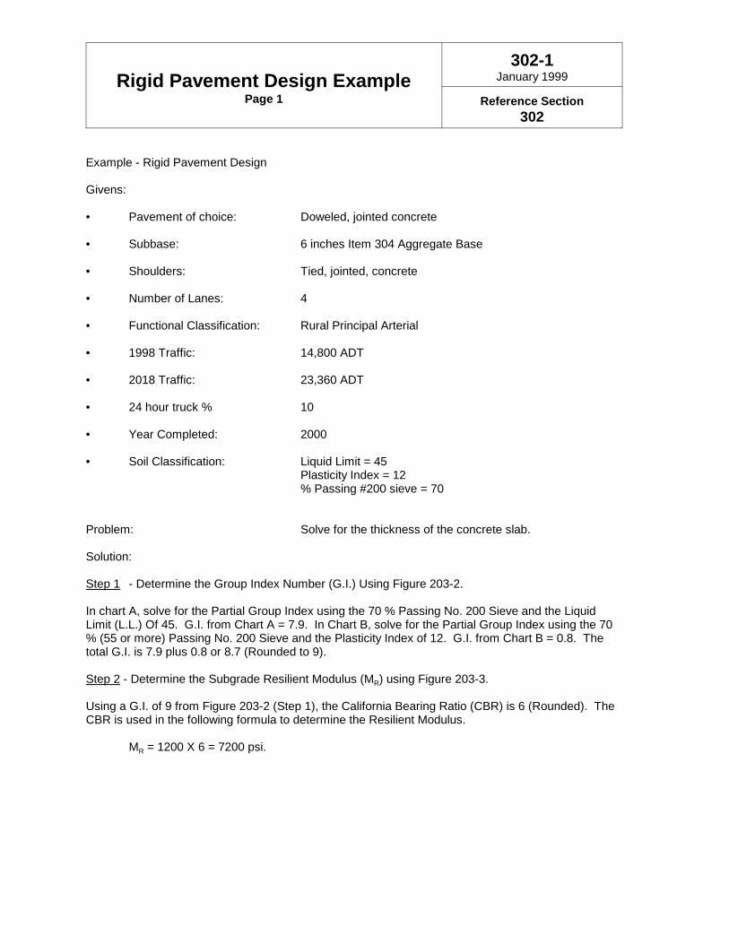
Rigid Pavement Design ExamplePage 1
302-1January 1999
Reference Section302
Example - Rigid Pavement Design
Givens:
• Pavement of choice: Doweled, jointed concrete
• Subbase: 6 inches Item 304 Aggregate Base
• Shoulders: Tied, jointed, concrete
• Number of Lanes: 4
• Functional Classification: Rural Principal Arterial
• 1998 Traffic: 14,800 ADT
• 2018 Traffic: 23,360 ADT
• 24 hour truck % 10
• Year Completed: 2000
• Soil Classification: Liquid Limit = 45Plasticity Index = 12% Passing #200 sieve = 70
Problem: Solve for the thickness of the concrete slab.
Solution:
Step 1 - Determine the Group Index Number (G.I.) Using Figure 203-2.
In chart A, solve for the Partial Group Index using the 70 % Passing No. 200 Sieve and the LiquidLimit (L.L.) Of 45. G.I. from Chart A = 7.9. In Chart B, solve for the Partial Group Index using the 70% (55 or more) Passing No. 200 Sieve and the Plasticity Index of 12. G.I. from Chart B = 0.8. Thetotal G.I. is 7.9 plus 0.8 or 8.7 (Rounded to 9).
Step 2 - Determine the Subgrade Resilient Modulus (MR) using Figure 203-3.
Using a G.I. of 9 from Figure 203-2 (Step 1), the California Bearing Ratio (CBR) is 6 (Rounded). TheCBR is used in the following formula to determine the Resilient Modulus.
MR = 1200 X 6 = 7200 psi.

Rigid Pavement Design ExamplePage 2
302-1June 1999
Reference Section302
Step 3 - Determine the 18-kip Equivalent Single Axle Loading (ESAL).
Since the project is expected to begin carrying traffic in the year 2000, the traffic period would be 2000to 2020, with a mid-year of 2010 and an interpolated ADT of 19,936.
Directional Distribution, D = 50 % (Figure 202-1)Lane Factor = .90 (Figure 202-1)B:C Ratio = 4:1 (Figure 202-1)B factor = 2.36 (Figure 202-1)C factor = 1.02 (Figure 202-1)
Using the equations given in Section 202.2:
ESAL's from B trucks: 19,936(0.10)(0.50)(0.90)(4/5)(2.36) = 1,693.8 ESAL
ESAL's from C trucks: 19,936(0.10)(0.50)(0.90)(1/5)(1.02) = 183.0 ESAL
Total ESAL's 1,876.8 ESAL’s per day
Design Period ESAL's = 1,876.8 X 365.25 days/yr. X 20 year = 13,709,842 say 13.7x10⁶ ESAL’s
Step 4 - Determine the Composite Modulus of Subgrade Reaction (Kc) using Figure 301-2.
Starting with the given subbase thickness (DSB) of 6", a line is projected up to the Subbase ElasticModulus (ESB) curve of 30,000 psi (Item 304 Aggregate Base from Figure 301-1). From this point onthe 30,000 psi curve, a line is projected to the right for future intersection. Similarly, from the 6"subbase thickness (DSB), a line is projected down to the Subgrade Resilient Modulus (MR) curve of1200 psi ( Figure 203-3, Step 2). From this point on the 1200 psi curve, a line is projected to the rightto the turning line and then projected up to intersect with previously projected line. This intersectionresults in a Composite Modulus of Subgrade Reaction (KC) of 400 pci.
Step 5 - Determine the Effective Modulus of Subgrade Reaction (K) using Figure 301-3.
The Composite Modulus of Subgrade Reaction (Kc) is 400 pci from Figure 301-2, Step 4. The Loss ofSupport (LS) for Item 304 Aggregate Base is 1.0 from Figure 301-1. This results in a K of 130 pci.
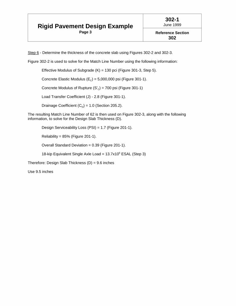
Rigid Pavement Design ExamplePage 3
302-1June 1999
Reference Section302
Step 6 - Determine the thickness of the concrete slab using Figures 302-2 and 302-3.
Figure 302-2 is used to solve for the Match Line Number using the following information:
Effective Modulus of Subgrade (K) = 130 pci (Figure 301-3, Step 5).
Concrete Elastic Modulus (EC) = 5,000,000 psi (Figure 301-1).
Concrete Modulus of Rupture (S’C) = 700 psi (Figure 301-1)
Load Transfer Coefficient (J) - 2.8 (Figure 301-1).
Drainage Coefficient (CD) = 1.0 (Section 205.2).
The resulting Match Line Number of 62 is then used on Figure 302-3, along with the followinginformation, to solve for the Design Slab Thickness (D).
Design Serviceability Loss (PSI) = 1.7 (Figure 201-1).
Reliability = 85% (Figure 201-1).
Overall Standard Deviation = 0.39 (Figure 201-1).
18-kip Equivalent Single Axle Load = 13.7x10⁶ ESAL (Step 3)
Therefore: Design Slab Thickness (D) = 9.6 inches
Use 9.5 inches

Rigid Pavement Design ChartSegment 1
302-2January 1999
Ref. Section & Figure302, 302-1 (step 6)

Rigid Pavement Design ChartSegment 2
302-3January 1999
Ref. Section & Figure302, 302-1 (step 6)
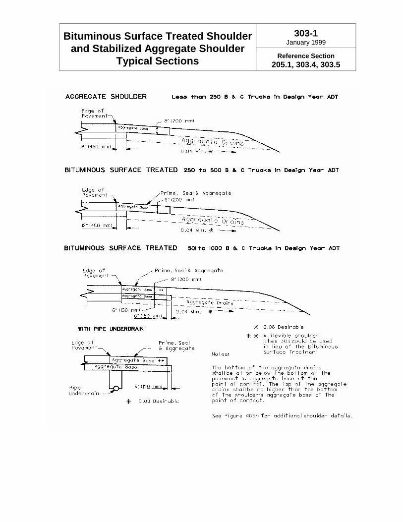
Bituminous Surface Treated Shoulderand Stabilized Aggregate Shoulder
Typical Sections
303-1January 1999
Reference Section205.1, 303.4, 303.5

Table of Contents
400 Flexible Pavement Design Procedures & Considerations 4-1400.1 Introduction . . . . . . . . . . . . . . . . . . . . . . . . . . . . . . . . . . . . . . . . . . . . . . . . . . 4-1
401 Design Parameters 4-1
402 Structural Number Determination 4-1402.1 Ramps and Interchanges . . . . . . . . . . . . . . . . . . . . . . . . . . . . . . . . . . . . . . . . 4-1
403 Typical Section and Buildup Considerations 4-1403.1 Typical Section Design . . . . . . . . . . . . . . . . . . . . . . . . . . . . . . . . . . . . . . . . . 4-1403.2 Shoulder Buildups . . . . . . . . . . . . . . . . . . . . . . . . . . . . . . . . . . . . . . . . . . . . . 4-2403.3 Edge Course Design . . . . . . . . . . . . . . . . . . . . . . . . . . . . . . . . . . . . . . . . . . . 4-2403.4 Paved Shoulder Edge Course Design . . . . . . . . . . . . . . . . . . . . . . . . . . . . . . 4-2
404 Lift Thickness and Specification Guidelines 4-2404.1 All Item 446 & 448 Type 1 and Type 2 Courses . . . . . . . . . . . . . . . . . . . . . . 4-3404.2 Superpave Specifications . . . . . . . . . . . . . . . . . . . . . . . . . . . . . . . . . . . . . . . 4-3404.3 Item 446 & 448 Asphalt Concrete Surface Course, Type 1, PG64-22 . . . . . 4-3404.4 Items 446 and 448 Asphalt Concrete Surface Course, Type 1H . . . . . . . . . . 4-3
404.4.1 Item 858 Asphalt Concrete Surface Course, 12.5 mm A & B (446 & 448). . . . . . . . . . . . . . . . . . . . . . . . . . . . . . . . . . . . . . . . . . . . . . . . . . . . 4-4
404.5 Item 446 Asphalt Concrete Intermediate Course, Type 1, PG64-22 . . . . . . . 4-4404.6 Item 446 Asphalt Concrete Intermediate Course, Type 2, PG64-28 & PG64-22
. . . . . . . . . . . . . . . . . . . . . . . . . . . . . . . . . . . . . . . . . . . . . . . . . . . . . . . . . . 4-4404.6.1 Item 858 Asphalt Concrete Intermediate Course, 19 mm A & B (446)
. . . . . . . . . . . . . . . . . . . . . . . . . . . . . . . . . . . . . . . . . . . . . . . . . . . . 4-4404.7 Item 448 Asphalt Concrete Intermediate Course, Type 1, PG64-28 & PG64-22
. . . . . . . . . . . . . . . . . . . . . . . . . . . . . . . . . . . . . . . . . . . . . . . . . . . . . . . . . . 4-4404.7.1 Item 858 Asphalt Concrete Intermediate Course, 9.5 mm A & B (448)
. . . . . . . . . . . . . . . . . . . . . . . . . . . . . . . . . . . . . . . . . . . . . . . . . . . . 4-5404.8 Item 448 Asphalt Concrete Intermediate Course, Type 2, PG64-28 & PG64-22
. . . . . . . . . . . . . . . . . . . . . . . . . . . . . . . . . . . . . . . . . . . . . . . . . . . . . . . . . . 4-5404.8.1 Item 848 Asphalt Concrete Intermediate Course, 19 mm A & B (448)
. . . . . . . . . . . . . . . . . . . . . . . . . . . . . . . . . . . . . . . . . . . . . . . . . . . . 4-5404.9 Item 301 Bituminous Aggregate Base, PG64-22 . . . . . . . . . . . . . . . . . . . . . . 4-5404.10 Item 302 Bituminous Aggregate Base, PG64-22 . . . . . . . . . . . . . . . . . . . . . 4-5404.11 Item 407 Tack Coat . . . . . . . . . . . . . . . . . . . . . . . . . . . . . . . . . . . . . . . . . . . 4-6404.12 Item 408 Prime Coat . . . . . . . . . . . . . . . . . . . . . . . . . . . . . . . . . . . . . . . . . . 4-6
405 Smoothness Specifications 4-6
January 1999 4-1
400 Flexible Pavement Design Procedures & Considerations400.1 Introduction
Flexible pavement design is based on the use ofthe Structural Number. The Structural Number isa regression coefficient expressing the structuralstrength of a pavement required for givencombinations of soil support (MR), traffic loading,and terminal serviceability. Flexible pavementscan be constructed with Superpave mixes, stonemastic mixes, contractor designed mixes, orODOT mixes; however, regardless of the mixdesign method used for a flexible pavement, theODOT/AASHTO method of pavement designcalculates the same required Structural Number.Once the Structural Number is determined, theflexible buildup is determined by using theappropriate structural coefficient for ODOTspecification materials. Alterations to ODOT’sConstruction and Material Specifications forasphalt concrete may require adjustments to theprocedures described herein.
Additional information on flexible pavement andproper construction practices can be found in theManual of Procedures for Flexible PavementConstruction put out by the Office of HighwayManagement
401 Design ParametersFlexible pavement design is based on relatively fewinput parameters. Serviceability, traffic loading(ESAL), subgrade strength (MR), reliability andoverall standard deviation have all been discussedin Section 200. The appropriate structuralcoefficients for ODOT asphalt concrete materialspecifications are found in Figure 401-1.
4 0 2 S t r u c t u r a l N u m b e rDeterminationAssembly of all the design input information isrequired prior to determination of design thickness.Structural Number is determined using thenomographs found in Figures 402-2 and 402-3. Anexample flexible pavement design is provided inFigure 402-1.
402.1 Ramps and Interchanges
Ramps and Interchanges also require traffic andsoils information for thickness design. However,some discretion must be used regarding thecalculation of ESAL’s. In general, use the lowerfunctional classification factors for Reliability, B:CRatio, and ESAL Conversion Factors.
403 Typical Section and BuildupConsiderations
403.1 Typical Section Design
Regardless of the SN required, a buildup whichincludes an aggregate base (Item 304) willgenerally provide better performance than a fulldepth asphalt concrete buildup. The aggregatebase is less sensitive to moisture than thesubgrade is and it separates the pavement furtherfrom the subgrade. An aggregate base isrecommended under all flexible pavements andparticularly when the thickness of a full depthflexible design is very thin, approximately 5 inches(~130 mm) (SN ~ 1.8) or less.
All surface and intermediate courses should beshould be specified in 0.25 inch (~5 mm)increments. Items 301 and 302 should bespecified in 0.5 inch (~10 mm) increments. Item304 is typically placed at 6 inches (~150 mm) thick.The minimum thickness for Item 304 is 4 inches(~100 mm) and it should be specified in 1 inch(~25 mm) increments.
When designing a flexible pavement, someconsideration should be given to reducing the totalnumber of separate lifts required. This can bedone by keeping in mind the maximum andminimum lift thicknesses for all of the materialsinvolved. Maximum and minimum lift thicknessescan be found either in the Construction andMaterials Specifications book or Section 404 in thisManual.
Flexible Pavement Design Procedures & Considerations
January 1999 4-2
403.2 Shoulder Buildups
Shoulders are used to provide an area for theaccommodation of disabled vehicles, for the lateralsupport of the base and surface courses, toimprove the safety of a highway, and for futuremaintenance of traffic operations duringmaintenance and rehabilitation work.
Shoulders for flexible pavements shall beconstructed of the same materials and thicknessesas the mainline pavement for all Interstate,freeways, expressways, and other multi-lanefacilities. This provides for the ability to have a hotlongitudinal joint at the pavement-shoulderinterface, provides a stable temporary pavementfor maintenance of traffic lane shifts, and reducesthe complexity of construction. Using other typesof shoulders, such as bituminous surface treated,stabilized aggregate, or turf shoulders should be inaccordance with Geometric Standards, discussedin the Location & Design Manual, Volume One -Roadway Design. Regardless of shoulder type,shoulder base and subgrade considerations shouldinclude directing drainage away from thepavement, rather than towards it. Examples oftypical sections depicting flexible pavement withdifferent types of shoulders are located in Figure403-1. Also refer to the Hydraulics Manual andSample Plan Sheets.
403.3 Edge Course Design
Item 304 Aggregate Base shall extend 6 inches(~150 mm) beyond the edge of the overlyingbituminous base for bituminous base courses 9inches (~225 mm) or less in thickness and 12inches (~300 mm) beyond the edge for bituminousbase courses thicker than 9 inches (~225 mm).
Item 302 Bituminous Aggregate Base shall extend6 inches (~150 mm) beyond the edge of theoverlying Item 301 Bituminous Aggregate Base forItem 301 courses 9 inches (~225 mm) or less inthickness and 12 inches (~300 mm) beyond theedge for Item 301 courses thicker than 9 inches(~225 mm). Each course, regardless of thenumber of lifts required by the specifications, shallbe designed and shown in a vertical plane.
Any base course shall extend beyond the edge ofthe overlying intermediate course a distance equalto the thickness of the surface course plus the
intermediate course or 4 inches (~100 mm),whichever is greater.
The outside edge of the intermediate course shallbe in alignment with the outside edge of thesurface course.
For concrete curbed sections, the asphalt concreteshall be paved to the face of the curb. Where thebottom courses of the asphalt pavement buildup liebelow the depth of the curb base, those layersshould be placed as a foundation for the curb, andshould have the proper edge course design asdiscussed above.
403.4 Paved Shoulder Edge CourseDesign
For shoulders that have the same buildup asmainline pavement refer to section 403.3. Whereshoulders are constructed with a buildup differentthan the mainline pavement, the outside edge ofeach course shall extend 6 inches (~150 mm)beyond the edge of the overlying course.
404 Lift Thickness andSpecification GuidelinesItems 402, 403, and 404 are no longer used onODOT administered projects.
ODOT asphalt concrete specifications containgradation requirements for all items. For optimumperformance of the pavement system, it isimportant to design the various lifts of asphaltconcrete items in order to achieve maximumsmoothness, durability, and densification. In orderto do this, some constraints are required regardingmaximum and minimum lift thicknesses in relationto the gradation of the item specified. Refer toODOT specification 441.02 and supplementalspecification 858 for gradation differences and BP-3.1 for feathering details. Of particular importance,it must be understood that by following theguidelines provided herein, typical sections whichrequire heavy mix designs should avoid specifyingoverlay thicknesses between 2.5 inches (~65 mm)and 3.25 inches (~83 mm).
Reference is made to Appendix B - PavementGuidelines for Treatment of High Stress Locations.

Flexible Pavement Design Procedures & Considerations
January 1999 4-3
404.1 All Item 446 & 448 Type 1 andType 2 Courses
The only difference between 446 and 448 is theway ODOT accepts the material duringconstruction. These materials are identical as theycome out of the plant. Because Item 446 carries adensity requirement for acceptance criteria, it isimportant to understand that Item 446 must only bespecified where a uniform thickness is used. Thefollowing guidelines are to be used for thedetermination of asphalt concrete materialspecification:
• Specify 446 for all projects which require aquantity of greater than 500 cubic yards(~500 cubic meters) of Type 1H surfacecourse.
• Specify 446 for all multi-lane resurfacingand rehabilitation projects.
• Specify 446 for all projects where includedquantities (Type 1 and Type 2) exceed2000 cubic yards (~1500 cubic meters).
• Specify 448 for all projects where 446 isnot required.
• Superpave shall be implemented inaccordance with direction provided by theDivision of Engineering Policy.
For projects which require 446, and only usevariable thickness at bridges and ramps in order totaper down to the required elevation, it isconsidered good practice to specify only the 446Item. ODOT construction and testing staff will onlytest the areas which are constructed as uniformthickness, and skip the testing of the variablethickness courses. This will eliminate a pay itemand other complications.
Where Item 446 is specified for the surface course,all Type 1 and Type 2 material specified should be446, except where a uniform lift thickness is notpossible.
404.2 Superpave Specifications
Superpave mixes are similar to 446 and 448 mixesexcept the mix design procedures as required inODOT CMS 441 are modified by SupplementalSpecification 858.
Type A and B requirements are found in SS 858.They control gradation bands and aggregateangularity. Type A has higher crush requirementsthat may mean the importation of aggregate insome areas of the state. This will raise productcost where districts have had good performancefrom locally available aggregates. Type B hasmore restrictive gradation bands but lower crushrequirements. Gradation requirements of Type Bmix will closely resemble Type 1H mix under 441.District testing and construction personnelknowledgeable in materials should be consultedprior to selection of Type A or B.
Pay descriptions for Superpave items contain areference to the maximum aggregate size used inthe mix. Accordingly, the 9.5 mm, 12.5 mm, and19.0 mm aggregate sizes are used for Superpavemix types. This reference to the maximumaggregate size replaces the reference to Type 1,Type 1H, and Type 2, respectively, used in non-superpave specifications, and has nothing to dowith any other measurement.
404.3 Item 446 & 448 Asphalt ConcreteSurface Course, Type 1, PG64-22
This item is intended to be used as a surfacecourse for Medium or Light traffic (see PN 417 and418). Lift thickness can vary between 1.25 inches(~32 mm) and 1.5 inches (~38 mm). Lift thicknesscan be reduced to 1 inch (~25 mm), but must be auniform thickness if 446 is specified.
Where Item 446 is specified for the surface course,all Type 1 material specified should be Item 446material, except where a uniform lift thickness isnot possible. Item 446 is to be specified only inuniform thickness.
404.4 Items 446 and 448 AsphaltConcrete Surface Course, Type 1H
All projects which require a quantity greater than500 cubic yards of Type 1H surface course shallspecify Item 446 for the surface course. Item 446is to be specified only in uniform thickness.
This item is intended to be used as a surfacecourse for a Heavy mix design (ADTT>1500, seePN 416). Type 1H mix is designed for maximumrut resistance at 1.5 inches (~38 mm) thick. Type1H is generally the most expensive mix and an
Flexible Pavement Design Procedures & Considerations
January 1999 4-4
increased thickness may not be economical. Inspecial situations where an intermediate course isnot possible, Type 1H may be specified up to amaximum of 2.5 inches (~65 mm). A 1H course cannot be placed properly at a thickness less than1.5 inches (~38 mm). Durability andconstructability problems will result. Best practiceis to use 1.5 inches (~38 mm).
A Type 1H will not have a performance grade (PG)asphalt cement specification. All 1H mixes aredesigned using an SBS or SBR polymer modifiedasphalt cement. For more detailed information seePN 101-96 and SS 1055.
404.4.1 Item 858 Asphalt Concrete SurfaceCourse, 12.5 mm A & B (446 & 448)
This Item is the Superpave version of Type 1H.The requirements of Section 404.4 apply.
404.5 Item 446 Asphalt ConcreteIntermediate Course, Type 1, PG64-22
This item is to be used as an intermediate coursein pavement overlay situations where the totaloverlay thickness is less than 3 inches (~75 mm).A Type 1 Intermediate Course is required becauseof the thin intermediate layer. Lift thickness for thisitem can be as thin as 1 inch (~25 mm) and asthick as 1.5 inches (~38 mm). Item 446 is to bespecified only in uniform thickness. Because thegrading of Type 1 mixes typically exhibit lessstability than that of a Type 1H or a Type 2 mixture,caution is advised when determining the use andthickness of this item, such that deformation isavoided. Best practice is to include some planingof the existing surface to allow a Type 2 material tobe used for the intermediate course.
This item is not to be used in combination with aType 1H surface course.
Where Item 446 is specified for the surface course,all Type 1 material specified should be Item 446material, except where a uniform lift thickness isnot possible.
404.6 Item 446 Asphalt ConcreteIntermediate Course, Type 2, PG64-28& PG64-22
This item is intended to be used as an intermediatecourse. The gradation of this mix requires the liftto be at least 1.75 inches (~45 mm) thick. In
special circumstances it is possible to allow this liftto be as thin as 1.5 inches (~38 mm), but this isdiscouraged. Item 446 is to be specified only inuniform thickness.
Caution is advised when determining the use ofand the thickness of this Item. ODOT CMSspecifies a maximum compaction lift of 3 inches(~75 mm). For a required layer of say 3.5 inches(~90 mm), the contractor will automatically placethe material in two lifts of 1.75 inches (~45 mm). Itis best to avoid specifying layers between 3 inches(~75 mm) and 3.5 inches (~90 mm) due to the 1.75inch (~45 mm) minimum lift thickness requirement.For most situations, the total thickness should notexceed 4.5 inches (~115 mm), as it would be betterto introduce the additional thickness into the 301 or302 or even the 304 base(s).
Specify PG64-28 for projects which have a Type1H surface mix, otherwise specify PG64-22.
404.6.1 Item 858 Asphalt Concrete IntermediateCourse, 19 mm A & B (446)
This Item is the Superpave version of Item 446Asphalt Concrete Intermediate Course, Type 2,PG64-28. The requirements of Section 404.6apply.
404.7 Item 448 Asphalt ConcreteIntermediate Course, Type 1, PG64-28& PG64-22
The intent of this item is for a scratch course.Uniform lift thickness for this item can be as thin as1 inch (~25 mm) and as thick as 1.5 inches (~38mm). This item can be used as a variablethickness course. For some rare occasions, whenthis lift is used as a leveling or wedge course, itmay be practical to stretch the lift thickness pastthe 1.5 inch (~38 mm) limit. For situations wherethe variability of the course thickness is excessive,say 0 inches to 2 inches (0 mm to ~50 mm),consideration should be given to pavement planingto allow for the use of a Type 2 mix which providesmore stability than a Type 1mix. This item can betapered to 0 inches (0 mm).
For projects which require 446 specifications, butneed this type of a leveling or wedge, there isnothing wrong with placing a 448 Intermediate,Type 1 under a 446 Surface. However, this item isnot to be used as uniform thickness layerunderneath a Type 1H layer. Where Item 446 isspecified for the surface course, all Type 1 material
Flexible Pavement Design Procedures & Considerations
January 1999 4-5
specified should be Item 446 material, exceptwhere a uniform lift thickness is not possible.
Specify PG64-28 for projects which have a Type1H surface mix, otherwise specify PG64-22.
404.7.1 Item 858 Asphalt Concrete IntermediateCourse, 9.5 mm A & B (448)
This Item is the Superpave version of Item 448Asphalt Concrete Intermediate Course, Type 1,PG64-28. The requirements of Section 404.7apply.
404.8 Item 448 Asphalt ConcreteIntermediate Course, Type 2, PG64-28& PG64-22
The intent of this item is the same as for Item 446Asphalt Concrete Intermediate Course, Type 2(Section 404.6). However, there is a difference.This item can also be used as a variable thicknesscourse. For some rare occasions, when this lift isused as a leveling or wedge course, it may bepractical to stretch the maximum recommendedthickness past the 4.5 inch (~115 mm) limit. As forthe minimum lift thickness, this item can bespecified to 0 inches (0 mm).
For projects which require 446 specifications, butneed this type of a leveling or wedge, it isacceptable to place a 448 Intermediate, Type 2under a 446 Surface Type 1. However, for hightraffic volumes, this practice should be avoided, ifpossible, to minimize pavement densification undertraffic.
Specify PG64-28 for projects which have a Type1H surface mix, otherwise specify PG64-22.
404.8.1 Item 848 Asphalt Concrete IntermediateCourse, 19 mm A & B (448)
This Item is the Superpave version of Item 448Asphalt Concrete Intermediate Course, Type 2,PG64-28. The requirements of Section 404.8apply.
404.9 Item 301 Bituminous AggregateBase, PG64-22
This item is to be used in conjunction with both asurface and intermediate course. The gradation ofthis mix requires the lift to be at least 3 inches (~75mm) thick. For most situations, this materialshould have 304 underneath, and a minimum of 3inches (~75 mm) of surface and intermediatecourse above. In special circumstances it ispossible to allow this lift to be as thin as 2.5 inches(~65 mm), but this is discouraged. This item maybe placed in variable thicknesses. ODOT CMSspecifies a maximum compaction lift of 6 inches(~150 mm). For a required layer of say 7 inches(~180 mm) the contractor will automatically placethe material in two lifts of 3.5 inches (~90 mm).For most situations, the total thickness should notexceed 10 inches (~250 mm), as it would be betterto introduce the additional thickness into a 302and/or a 304 base(s). This material can handletraffic during construction due to phasing but careshould be taken to minimize high traffic volumecontact. In high traffic volume situations, anintermediate course is preferred for maintenanceof traffic, particularly over the winter.
404.10 Item 302 Bituminous AggregateBase, PG64-22
This item is to be used in conjunction with both asurface and intermediate course. This mix wasdeveloped for use with thick flexible pavementswhere high volume truck traffic exists. When liftthicknesses and maintenance of traffic operationsallow, Item 302 is preferred over Item 301. Thegradation of this mix requires the lift to be at least4 inches (~100 mm) thick. ODOT CMS specifiesa maximum compaction lift of “less than 8 inches(200 mm).” For a required layer of exactly 8 inches(~200 mm) the contractor will automatically placethe material in two lifts of 4 inches (~100 mm).This item may be placed in variable thicknesses.For most situations, this material should have 304underneath, and a minimum of 3 inches (~75 mm)of surface and intermediate course above. It is notnecessary to put a 301 course above a 302 course.Placement of 301 below 302 is illogical. Item 302should not be used for maintenance of traffic formore than approximately 60 days and never overthe winter. If it is necessary to maintain traffic formore than 60 days or over winter, the top 3 inches(75 mm) of the 302 could be changed to 301, ormore preferable, the project should be scheduledto allow the intermediate course to be placed formaintenance of traffic.

Flexible Pavement Design Procedures & Considerations
January 1999 4-6
404.11 Item 407 Tack Coat
A tack coat is used to glue an asphalt layer to thelayer below. Tack coats are required anytime asurface course is placed on an intermediate course(CMS 407.052). Tack coat is recommendedanytime new asphalt is being placed on an existingsurface with two exceptions. Tack coat should notbe used under a bondbreaker layer for anunbonded concrete overlay. Tack coat also shouldnot be used on rubblized concrete.
Actual application rates of tack coat are set in thefield. The most common application rate used forestimating quantities is 0.75 gallons per squareyard (0.34 L/m2). Estimated application rate of tackfor surface courses placed on intermediatecourses is 0.04 gallons per square yard (.018L/m2).
404.12 Item 408 Prime Coat
Prime coats are applied to Item 304 AggregateBase to prevent binder from the asphalt from beingabsorbed into the 304 or under a free drainingbase to prevent erosion of the 304. Prime coatsare required under all free draining bases, seeSection 205.1.4. In the absence of a free drainingbase, a prime coat is recommended anytime thethickness of the Bituminous Aggregate Base (Item
301 or 302) is less than or equal to the thickness ofthe 304. For thicker pavements a prime coat maynot be necessary but is still optional.
Application rate for prime coat is always 0.4 gallonsper square yard (1.8 L/m2).
405 Smoothness SpecificationsIncentive/disincentive for smoothness is specifiedusing Proposal Note 414 - 446 SurfaceSmoothness Requirements. The Note is to beused on projects which have a 446-type surfacemix, either conventional or Superpave. The trafficvolume should be either heavy or medium (see PN416 and 417). The project should be greater thanone center-line mile (~1.6 center-line km) ofdivided highway with two or more lanes perdirection. On resurfacing projects, the totalthickness of new asphalt must be at least 4 inches(~100 mm) if the existing surface is not planed, or3 inches (~75 mm) if the existing surface is planed.When placing an overlay directly on concrete whichhas either never been overlayed or has had theexisting overlay removed, the total thickness ofasphalt must be at least 4 inches (~100 mm). Theexception to this is projects which involve buildinga new composite pavement do not require the 4-inch (~100 mm) minimum.

400 Flexible Pavement Design Procedures & Considerations
List of FiguresFigure Date Subject
401-1 January 1999 Flexible Pavement Structural Coefficients
402-1 January 1999 Flexible Pavement Design Example
402-2 January 1999 Flexible Pavement Design Chart Segment 1
402-3 January 1999 Flexible Pavement Design Chart Segment 2
403-1 January 1999 Bituminous Surface Treated Shoulder and StabilizedAggregate Shoulder Typical Sections

Flexible Pavement StructuralCoefficients
401-1January 1999
Reference Section401
ASPHALT CONCRETE STRUCTURAL COEFFICIENTS
Material EnglishCoefficient
MetricCoefficient
Items 446, 448 - Asphalt Concrete Surface Courses 0.35 0.0138
Items 446, 448 - Asphalt Concrete Intermediate Courses 0.35 0.0138
Items 301, 302 - Bituminous Aggregate Base Courses 0.35 0.0138
Item Special - SMA mixes, Superpave mixes 0.35 0.0138
Cracked & Seated Plain Concrete Pavement 0.27 0.0106
Existing Asphalt Concrete - old, oxidized, & weathered 0.23 0.0092
Item 304 - Aggregate Base 0.14 0.0055
Item Special - Rubblize & Roll Existing Concrete Pavement 0.14 0.0055
Items 306, 307, 855 - Free Draining Base Layers 0.14 0.0055
Asphalt Concrete Drainage Factor = 1.0
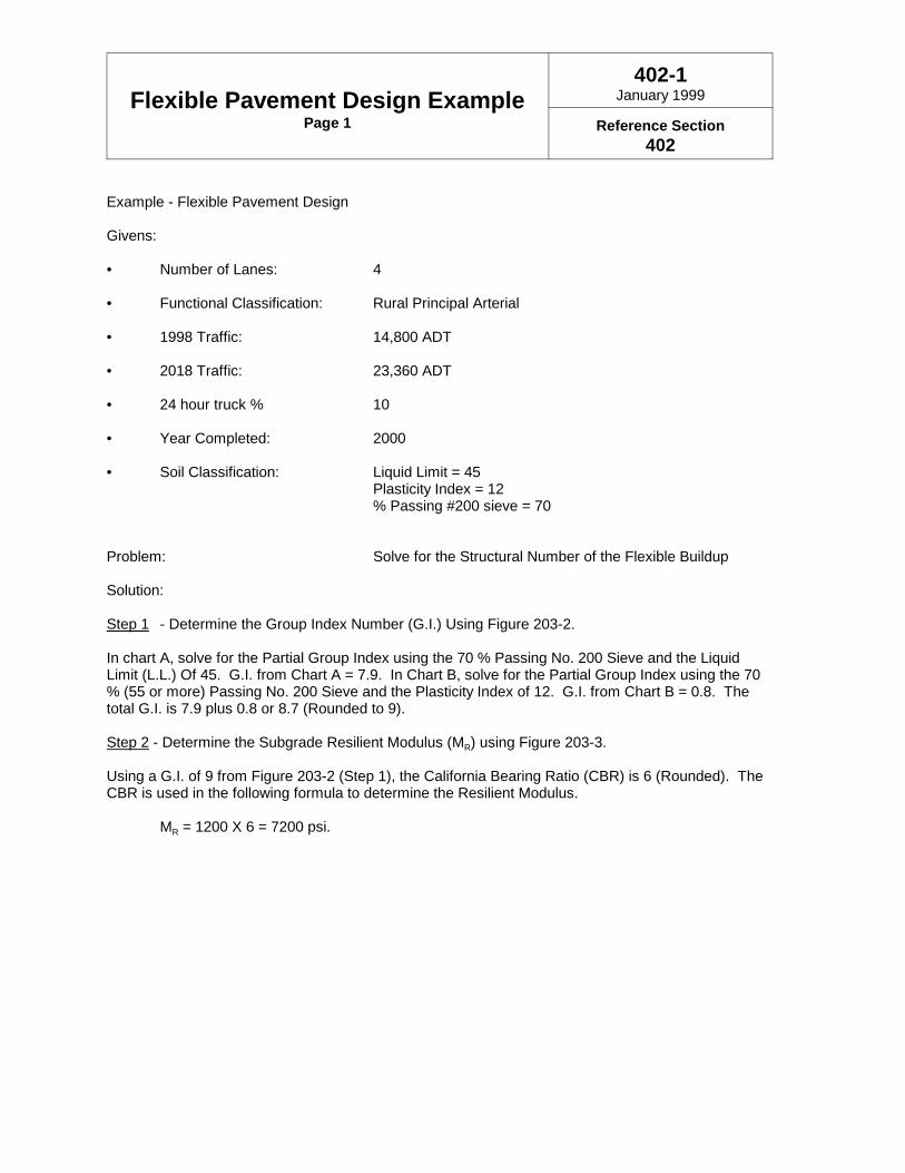
Flexible Pavement Design ExamplePage 1
402-1January 1999
Reference Section402
Example - Flexible Pavement Design
Givens:
• Number of Lanes: 4
• Functional Classification: Rural Principal Arterial
• 1998 Traffic: 14,800 ADT
• 2018 Traffic: 23,360 ADT
• 24 hour truck % 10
• Year Completed: 2000
• Soil Classification: Liquid Limit = 45Plasticity Index = 12% Passing #200 sieve = 70
Problem: Solve for the Structural Number of the Flexible Buildup
Solution:
Step 1 - Determine the Group Index Number (G.I.) Using Figure 203-2.
In chart A, solve for the Partial Group Index using the 70 % Passing No. 200 Sieve and the LiquidLimit (L.L.) Of 45. G.I. from Chart A = 7.9. In Chart B, solve for the Partial Group Index using the 70% (55 or more) Passing No. 200 Sieve and the Plasticity Index of 12. G.I. from Chart B = 0.8. Thetotal G.I. is 7.9 plus 0.8 or 8.7 (Rounded to 9).
Step 2 - Determine the Subgrade Resilient Modulus (MR) using Figure 203-3.
Using a G.I. of 9 from Figure 203-2 (Step 1), the California Bearing Ratio (CBR) is 6 (Rounded). TheCBR is used in the following formula to determine the Resilient Modulus.
MR = 1200 X 6 = 7200 psi.

Flexible Pavement Design ExamplePage 2
402-1January 1999
Reference Section402
Step 3 - Determine the 18 Kip Equivalent Single Axle Loading (ESAL)
Since the project is expected to begin carrying traffic in the year 2000, the traffic period would be 2000to 2020, with a mid-year of 2010 and an interpolated ADT of 19,936.
Directional Distribution, D = 50 % (Figure 202-1)Lane Factor = .90 (Figure 202-1)B:C Ratio = 4:1 (Figure 202-1)B factor = 1.51 (Figure 202-1)C factor = 0.66 (Figure 202-1)
ESAL's from B trucks: 19,936(0.10)(0.50)(0.90)(4/5)(1.51) = 1,083.7 ESAL
ESAL's from C trucks: 19,936(0.10)(0.50)(0.90)(1/5)(0.66) = 118.4 ESAL
Total ESAL’s 1,202.1 ESAL per day
Design Period ESAL’s = 1,202.1 X 365.25 days/yr. X 20 year = 8,781,639 say 8.8 x 10⁶ ESAL
Step 4
Determine the Design Structural Number (SN) using Figures 402-2 and 402-3. In Figure 402-2, solvefor the Match Line Number using the following information:
Reliability = 85 % (Figure 201-1)Overall Standard Deviation = 0.49 (Figure 201-1)18-kip Single Axle Loads = 8.8 x 10⁶ ESAL (Step 3)Resilient Modulus = 7,200 psi (Step 2)
The resulting Match Line Number of 39 is then used in Figure 402-3, along with the DesignServiceability Loss of 2.0 (Figure 201-1), to solve for the Design Structural Number (SN).
Therefore: Design Structural Number (SN) = 4.50
Step 5
Design the typical section using the layer coefficients found in Figure 401-1. The total SN for thepavement buildup shall equal or exceed the SN (SN = 4.5) determined from Figure 402-3.

Flexible Pavement Design ExamplePage 3
402-1January 1999
Reference Section402
By checking the current year Average Daily Truck Traffic (ADTT, see PN 416), determine the type ofsurface mix required.
14,800 X 0.10 = 1,480 trucks < 1,500 trucks (see Note)Therefore, use a Type I surface course at a minimum lift thickness of 1.25 inches.
The following buildup is not the only solution, but will satisfy the required SN:
Material
448 Asphalt Concrete Surface Course, Type 1, PG64-22448 Asphalt Concrete Intermediate Course, Type 2, PG64-22301 Bituminous Aggregate Base304 Aggregate Base
Thickness
1.25"1.75"7.5"6"
16.5"
Coefficient
0.350.350.350.14
SN
0.440.612.620.84
4.51
Note: 1,480 trucks per day (ADTT) is so close to 1,500 that it may be appropriate to specifya heavy mix design. Also see PN 416, and Appendix B

Flexible Pavement Design ChartSegment 1
402-2January 1999
Ref. Section & Figure402, 402-1(step 4)

Flexible Pavement Design ChartSegment 2
402-3January 1999
Ref. Section & Figure402, 402-1(step 4)

Bituminous Surface Treated Shoulderand Stabilized Aggregate Shoulder
Typical Sections
403-1January 1999
Reference Section205.1

Table of Contents
500 Pavement Design Procedures for Minor Rehabilitation 5-1500.1 Introduction . . . . . . . . . . . . . . . . . . . . . . . . . . . . . . . . . . . . . . . . . . . . . . . . . . 5-1
501 Deflection Measuring Equipment 5-1501.1 Dynaflect . . . . . . . . . . . . . . . . . . . . . . . . . . . . . . . . . . . . . . . . . . . . . . . . . . . . 5-1501.2 Falling Weight Deflectometer . . . . . . . . . . . . . . . . . . . . . . . . . . . . . . . . . . . . 5-1
502 Deflection Testing and Analysis 5-1502.1 General . . . . . . . . . . . . . . . . . . . . . . . . . . . . . . . . . . . . . . . . . . . . . . . . . . . . . 5-1502.2 Analysis . . . . . . . . . . . . . . . . . . . . . . . . . . . . . . . . . . . . . . . . . . . . . . . . . . . . . 5-2
502.2.1 Edwards Ratio . . . . . . . . . . . . . . . . . . . . . . . . . . . . . . . . . . . . . . . . 5-2502.2.2 W5 vs. CBR . . . . . . . . . . . . . . . . . . . . . . . . . . . . . . . . . . . . . . . . . . 5-2502.2.3 Load Transfer . . . . . . . . . . . . . . . . . . . . . . . . . . . . . . . . . . . . . . . . 5-2502.2.4 Joint Support Ratio . . . . . . . . . . . . . . . . . . . . . . . . . . . . . . . . . . . . 5-2
502.3 Factors Affecting Deflections . . . . . . . . . . . . . . . . . . . . . . . . . . . . . . . . . . . . . 5-2502.3.1 Loading . . . . . . . . . . . . . . . . . . . . . . . . . . . . . . . . . . . . . . . . . . . . . 5-2502.3.2 Climate . . . . . . . . . . . . . . . . . . . . . . . . . . . . . . . . . . . . . . . . . . . . . . 5-2502.3.3 Pavement Conditions . . . . . . . . . . . . . . . . . . . . . . . . . . . . . . . . . . . 5-3
503 Overlay Design Procedure 5-3503.1 Introduction . . . . . . . . . . . . . . . . . . . . . . . . . . . . . . . . . . . . . . . . . . . . . . . . . . 5-3503.2 Rigid Pavements . . . . . . . . . . . . . . . . . . . . . . . . . . . . . . . . . . . . . . . . . . . . . . 5-3503.3 Flexible Pavements . . . . . . . . . . . . . . . . . . . . . . . . . . . . . . . . . . . . . . . . . . . . 5-4503.4 Composite Pavements . . . . . . . . . . . . . . . . . . . . . . . . . . . . . . . . . . . . . . . . . . 5-4
503.4.1 Brick Pavements . . . . . . . . . . . . . . . . . . . . . . . . . . . . . . . . . . . . . . 5-4
504 Minor Rehabilitation Strategies 5-5504.1 Asphalt Considerations . . . . . . . . . . . . . . . . . . . . . . . . . . . . . . . . . . . . . . . . . 5-5504.2 Milling . . . . . . . . . . . . . . . . . . . . . . . . . . . . . . . . . . . . . . . . . . . . . . . . . . . . . . . 5-5
504.2.1 Brick Pavements . . . . . . . . . . . . . . . . . . . . . . . . . . . . . . . . . . . . . . 5-5504.3 Pavement Repair . . . . . . . . . . . . . . . . . . . . . . . . . . . . . . . . . . . . . . . . . . . . . . 5-5
504.3.1 Rigid and Composite Pavements . . . . . . . . . . . . . . . . . . . . . . . . . 5-5504.3.2 Flexible Pavements . . . . . . . . . . . . . . . . . . . . . . . . . . . . . . . . . . . . 5-6504.3.3 Brick Pavements . . . . . . . . . . . . . . . . . . . . . . . . . . . . . . . . . . . . . . 5-6
504.4 Reflective Crack Control . . . . . . . . . . . . . . . . . . . . . . . . . . . . . . . . . . . . . . . . 5-7504.4.1 Sawing and Sealing . . . . . . . . . . . . . . . . . . . . . . . . . . . . . . . . . . . . 5-7504.4.2 Fabrics and Geogrids . . . . . . . . . . . . . . . . . . . . . . . . . . . . . . . . . . 5-7
504.5 Concrete Pavement Restoration . . . . . . . . . . . . . . . . . . . . . . . . . . . . . . . . . . 5-7504.6 Geometric Issues . . . . . . . . . . . . . . . . . . . . . . . . . . . . . . . . . . . . . . . . . . . . . . 5-7504.7 Pavement Widening . . . . . . . . . . . . . . . . . . . . . . . . . . . . . . . . . . . . . . . . . . . 5-7
504.7.1 Rigid Pavement . . . . . . . . . . . . . . . . . . . . . . . . . . . . . . . . . . . . . . . 5-8504.7.2 Flexible Pavement . . . . . . . . . . . . . . . . . . . . . . . . . . . . . . . . . . . . . 5-8504.7.3 Composite Pavement . . . . . . . . . . . . . . . . . . . . . . . . . . . . . . . . . . 5-8

January 1999 5-1
500 Pavement Design Procedures for Minor Rehabilitation500.1 Introduction
Minor rehabilitations should occur when thepavement has deteriorated beyond the point atwhich preventive maintenance is effective but doesnot yet require major rehabilitation. Minorrehabilitations usually consist of some combinationof milling, repair, and overlay. ODOT designsminor rehabilitation overlays using a deflection-based procedure and twelve-year trafficprojections.
501 Deflection MeasuringEquipmentDeflection measuring equipment imposes a loadon the pavement and measures the response. Thedeflections can be correlated to the structuralcondition of the pavement and the subgrade.Designers can interpret the deflections and providerecommendations for pavement rehabilitation.ODOT has two kinds of deflection measuringequipment or Non-Destructive Testing (NDT)devices: the Dynaflect, and the Falling WeightDeflectometer. Both are described below;however, this manual is written specifically for usewith the Dynaflect.
501.1 Dynaflect
The Dynaflect is an electro-mechanical deviceused for measuring pavement deflection. It istrailer-mounted and can be towed by a standardvehicle. A static weight of 2000 pounds (~908 kg)is applied to the pavement through a pair of 4-inchwide by 16-inch (~406 mm) diameter rubber-coated steel wheels placed 20 inches (~508 mm)apart. Two counter-rotating eccentric weightsproduce a dynamic force of 1000 pounds (~454kg), peak-to-peak, at a frequency of eight cyclesper second. The dynamic force is superimposedon the static force and the deflections aremeasured by five velocity transducers(geophones). The first geophone is locatedbetween the steel wheels with the rest spacedtwelve inches (~305 mm) apart. The deflectionsare recorded on a computer in the tow vehicle.
501.2 Falling Weight Deflectometer
The Falling Weight Deflectometer (FWD) is animpact load response device used to measurepavement deflection. The impact force is createdby dropping a weight of 110, 220, 440, or 660
pounds (~50, 100, 200, 300 kg) from a height of0.8 to 15 inches (~20 to 380 mm). By varying thedrop height and weight, a peak force ranging from1500 to 24,000 pounds (~6.7 to 106.8 kN) can begenerated. The load is transmitted to thepavement through a loading plate, 11.8 inches(~300 mm) in diameter, to provide a load pulse inthe form of a half sine wave with a duration from 25to 30 ms. The actual magnitude of load appliedmay depend on the stiffness of the pavement andis measured by a load cell. The deflections aremeasured by seven velocity transducers. Onetransducer is located at the center of the loadingplate while the remaining six can be placed atlocations up to 7.4 feet (~2.25 m) from the center.The deflections are recorded on a computerlocated in the tow vehicle.
502 Deflection Testing andAnalysis
502.1 General
Deflection measurements taken when thesubgrade is frozen are meaningless for design.The testing season in Ohio runs approximatelyApril through November. Requests for Dynaflecttesting should be made to the Research andDevelopment Section of the Office of MaterialsManagement with a copy of the request to thePavement Design Section in the same Office.Requests are honored on a first-come, first-servedbasis, subject to scheduling considerations.Requests made too late in the season may not betested until the following year. Research testingneeds take priority during many of the summermonths. The best time to submit requests is justprior to and early in the testing season. Allrequests must include the exact limits of theproject using the current English straight-linediagrams issued by the Office of TechnicalServices, even for projects being developed inmetric units.
Deflection measurements represent a snapshot ofthe pavement at that time. As the pavementcontinues to deteriorate, the snapshot changes.Therefore, deflection data should not be obtainedmore than four years prior to construction. If theproject is delayed such that the data will be morethan four-years old, new deflection measurementsshould be requested and the design checkedagainst the new measurements to ensure validity.

Pavement Design Procedures for Minor Rehabilitation
January 1999 5-2
502.2 Analysis
Deflection measurements yield a great deal ofinformation about the pavement when properlyinterpreted. This Manual is not intended to makethe reader an expert in analyzing deflection data.A training course is available which discusses thedata analysis in much greater detail.
502.2.1 Edwards Ratio
One of the more useful parameters derived fromthe Dynaflect data is called the Edwards Ratio.Named after William F. Edwards, former BureauChief of Research and Development at ODOT.The Edwards Ratio states that if the w1 sensorreading divided by the w5 sensor reading is greaterthan three, the pavement is acting as a flexiblepavement and should be analyzed as such. If it isless than three, the pavement is acting as a rigidpavement and should be analyzed as such. Thisis very useful when trying to decide how to analyzea brick pavement or an existing break & seat orcrack & seat.
502.2.2 W5 vs. CBR
The w5 sensor provides an estimate of thesubgrade strength. The chart in figure 203-3shows the relationship between the average w5sensor reading plus two standard deviations andthe CBR value. The average w5 reading and thestandard deviation are given on the Dynaflectprintout.
502.2.3 Load Transfer
The Load Transfer factor can indicate joints whichhave deteriorated and are no longer effectivelytransferring the load. Load Transfer factors lessthan 0.70 indicate poor load transfer. Factorsgreater than 0.70 do not necessarily indicate goodjoints. If the pavement is warm, the joints may belocked up and showing better load transfer thanactually exists. The Load Transfer factor is the w2sensor divided by the w1 sensor, both from the jointapproach reading. A graph of Load Transfervalues is given by the UTPLOT program (Section503.1).
502.2.4 Joint Support Ratio
The Joint Support Ratio is another measure of thejoint’s effectiveness. Joint Support Ratio is the w1sensor from the joint leave reading divided by thew1 sensor from the joint approach reading. Joint
Support Ratios between 0.50 and 1.50 areconsidered good. Ratios outside this rangeindicate probable voids under the joint. Voids arealso likely anytime the w1 sensor reading is above1.0. The UTPLOT program provides a graph ofthe Joint Support Ratio.
502.3 Factors Affecting Deflections
The major factors that influence deflections includeloading, climate and pavement conditions. Thesefactors must be carefully considered whenconducting nondestructive tests.
502.3.1 Loading
The magnitude and duration of loading have agreat influence on pavement deflections. It isdesirable that the NDT device applies a load to thepavement similar to the actual design load, e.g., a9000 pound (~4086 kg) wheel load. Unfortunately,not every commercially available NDT is capable ofsimulating the design load. Some can simulate themagnitude of the design load but not its duration orfrequency.
Due to the nonlinear or stress-sensitive propertiesof most paving materials, pavement deflections arenot proportional to load. Test results obtained forlight loads must be extrapolated to those for heavyloads. Because extrapolation may lead tosignificant error for nonlinear paving materials, theuse of NDT devices that produce loadsapproximating those of heavy truck loads isrecommended by most researchers.
In 1989, FHWA/ODOT published Technical ReportNo. FHWA/OH-89/020 titled: Implementation of aDynamic Deflection System for Rigid and FlexiblePavements in Ohio. This research study lookedinto the non-linearity problems associated withNDT using light loading as compared to normaltruck loads. The relevant conclusion was: “on theaverage, pavement deflections obtained by theDynaflect and the FWD correlated quite well andpavement non-linearity was not as significant aswas anticipated.”
502.3.2 Climate
Temperature and moisture are the two climaticfactors that affect pavement deflections. Forasphalt pavements, higher temperatures cause theasphalt binder to soften and increase deflections.For concrete pavements, temperature in the formof overall change or thermal gradient has a
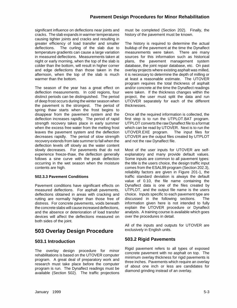
Pavement Design Procedures for Minor Rehabilitation
January 1999 5-3
significant influence on deflections near joints andcracks. The slab expands in warmer temperaturescausing tighter joints and cracks and resulting ingreater efficiency of load transfer and smallerdeflections. The curling of the slab due totemperature gradients can cause a large variationin measured deflections. Measurements taken atnight or early morning, when the top of the slab iscolder than the bottom, will result in higher cornerand edge deflections than those taken in theafternoon, when the top of the slab is muchwarmer than the bottom.
The season of the year has a great effect ondeflection measurements. In cold regions, fourdistinct periods can be distinguished. The periodof deep frost occurs during the winter season whenthe pavement is the strongest. The period ofspring thaw starts when the frost begins todisappear from the pavement system and thedeflection increases rapidly. The period of rapidstrength recovery takes place in early summerwhen the excess free water from the melting frostleaves the pavement system and the deflectiondecreases rapidly. The period of slow strengthrecovery extends from late summer to fall when thedeflection levels off slowly as the water contentslowly decreases. For pavements that do notexperience freeze-thaw, the deflection generallyfollows a sine curve with the peak deflectionoccurring in the wet season when the moisturecontents are high.
502.3.3 Pavement Conditions
Pavement conditions have significant effects onmeasured deflections. For asphalt pavements,deflections obtained in areas with cracking andrutting are normally higher than those free ofdistress. For concrete pavements, voids beneaththe concrete slabs will cause increased deflections,and the absence or deterioration of load transferdevices will affect the deflections measured onboth sides of the joint.
503 Overlay Design Procedure
503.1 Introduction
The overlay design procedure for minorrehabilitations is based on the UTOVER computerprogram. A great deal of preparatory work andresearch must take place before the computerprogram is run. The Dynaflect readings must beavailable (Section 502). The traffic projections
must be completed (Section 202). Finally, thehistory of the pavement must be known.
The history is required to determine the actualbuildup of the pavement at the time the Dynaflectmeasurements were taken. There are manysources for this information such as historicalplans, the pavement management systemdatabase, the joint repair database, etc. On pastoverlay projects where existing asphalt was milled,it is necessary to determine the depth of milling orat least a reasonable estimate. The UTOVERprogram requires the total thickness of asphaltand/or concrete at the time the Dynaflect readingswere taken. If the thickness changes within theproject, the user must split the data and runUTOVER separately for each of the differentthicknesses.
Once all the required information is collected, thefirst step is to run the UTPLOT.BAT program.UTPLOT converts the raw Dynaflect file to a formatwhich can be read by UTOVER. Next is to run theUTOVER.EXE program. The input files forUTOVER are the output files created by UTPLOTand not the raw Dynaflect file.
Most of the user inputs for UTOVER are self-explanatory and many provide default values.Some inputs are common to all pavement types:the title is the users choice, the design traffic inputcomes from the ESAL99 program (Section 202.3),reliability factors are given in Figure 201-1, thetraffic standard deviation is always the defaultvalue of 0.10, the file name containing theDynaflect data is one of the files created byUTPLOT, and the output file name is the userschoice. Inputs specific to each pavement type arediscussed in the following sections. Theinformation given here is not intended to fullyexplain the UTOVER procedure or Dynaflectanalysis. A training course is available which goesover the procedures in detail.
All of the inputs and outputs for UTOVER areexclusively in English units.
503.2 Rigid Pavements
Rigid pavement refers to all types of exposedconcrete pavement with no asphalt on top. Theminimum overlay thickness for rigid pavements isthree inches. Pavements which require an overlayof about one inch or less are candidates fordiamond grinding instead of an overlay.

Pavement Design Procedures for Minor Rehabilitation
January 1999 5-4
Most of the rigid pavement inputs to UTOVER usethe default values. The thickness of the existingpavement is obtained from the history. Use thedefault value for Poisson’s Ratio of the existingconcrete. Use the default values for elasticmodulus, initial PSI, terminal PSI, modulus ofrupture, and the drainage coefficient. The loadtransfer coefficient (J) is dependent on thespecifics of the existing pavement. A list of J-factors for existing pavements is given in Figure503-1. A rigid pavement with the majority of thejoints replaced with flexible repairs, should use a J-factor for a pavement with no load transfer at thejoints.
503.3 Flexible Pavements
Flexible pavements are made up entirely of asphaltwith or without an aggregate or macadam base.Previously rubblized pavements are consideredflexible pavement. Previous break & seat andcrack & seat projects may be flexible pavement butare more likely acting as composite pavement.The Edwards Ratio can help in determiningpavement type in questionable cases.
Most of the inputs for flexible pavement require theuser to enter values. The whole thickness offlexible pavement above subgrade is exactly whatthe name implies: the thickness of the aggregatebase, macadam base, or rubblized concrete plusthe entire thickness of asphalt on top. Thethickness of the surface AC layer is required fortemperature adjustment. It is not a sensitive input.Best practice is to use the thickness of the existingsurface and intermediate courses combined.Pavement surface temperature is recorded on theDynaflect printout. Where additional temperatureswere recorded for the same data, a weightedaverage should be used. The 5-day mean airtemperature should be obtained frommeteorological records, if available. In theabsence of actual temperature data, the morningpavement surface temperature should be used asthe basis for the 5-day mean temperature. Someadjustment is allowed if the user is aware ofspecific temperature conditions in the days justprior to the Dynaflect readings. Initial and terminalPSI are always 4.5 and 2.5, respectively.
503.4 Composite Pavements
Composite pavements are concrete overlaid withasphalt. Most old break & seat and crack & seatprojects should be analyzed as compositepavements. Any asphalt-surfaced road with somesort of concrete underneath, that is acting like arigid pavement according to the Edwards Ratio,should be analyzed as a composite pavement.
The inputs for composite pavement are nearlyidentical to rigid pavement with the addition ofasphalt on top (Section 503.2). Thickness ofexisting AC layer is the thickness of all the asphalton top of the concrete. The default values shouldbe used for Poisson’s Ratio and the resilientmodulus of the asphalt. The thickness of existingPCC slab is obtained from the history or coring.Use default values for Poisson’s Ratio, newconcrete elastic modulus, initial PSI, terminal PSI,new concrete modulus of rupture, and drainagecoefficient. The load transfer coefficient (J) isdependent on the specifics of the existingpavement. A list of J-factors for existingpavements is given in Figure 503-1. A compositepavement with the majority of the joints replacedwith flexible repairs, should use a J-factor for apavement with no load transfer at the joints.
503.4.1 Brick Pavements
Most brick pavements in Ohio were built on aconcrete base and have since been overlayed withasphalt and thus are a special kind of compositepavement. The UTOVER program was notdesigned for use on brick pavements. TheEdwards Ratio can help the user decide which typeof pavement to use to analyze the brick. Wheninputting the thicknesses, it is up to the user todecide if the bricks count as concrete or asasphalt.
Since brick pavements occur mostly in urbanareas, there are likely to be geometric problemssuch as curb reveal, driveways, etc. A possiblesolution is to design a crack and seat overlay (seeSection 600) with removal of both the asphalt andthe bricks. This should only be done if the sectionhas been cored to determine the condition andthickness of the existing concrete. The actualcracking and seating operation should not be

Pavement Design Procedures for Minor Rehabilitation
January 1999 5-5
performed as the concrete is likely already wellcracked. This method merely eliminates the needto run UTOVER on a brick pavement which it wasnot intended for and can sometimes result inexcessive overlay thicknesses.
504 Minor Rehabil i tat ionStrategiesAs stated before, minor rehabilitations generallyconsist of some combination of milling, repair, andoverlay. The structural overlay thickness neededis determined from the Dynaflect and the UTOVERprogram. Even if UTOVER says that no additionalstructure is needed, an overlay may still berequired to correct functional deficiencies. Thethickness of a functional overlay is selected basedon factors such as milling depth, lift thicknessrequirements, vertical clearance, curb reveal, etc.A functional overlay with milling should never resultin thinner pavement than existed beforehand. Theother minor rehabilitation actions are at thedesigner’s discretion based on the condition of thepavement. The actions selected should be thoserequired to reach the full design period for minorrehabilitation projects.
504.1 Asphalt Considerations
All asphalt items used in minor rehabilitationoverlays should conform to the guidelines given inSection 404. Prior to completion of the plans, allasphalt items specified should be discussed withthe District Engineer of Tests or his designee. Thisis important to ensure proper binder grades andmix specifications are specified.
A minimum of 3 inches (~75 mm) of asphalt isrequired over any concrete or brick surface.
504.2 Milling
Milling is always recommended. A milled surfaceallows for mechanical interlock between theexisting pavement and the overlay which helpsprevent rutting and debonding. Milling removes theold, raveled, oxidized asphalt which, if left in place,would be a weak layer in the pavement structureand would tend to hold water due to the lowerbinder content. Milling reduces the overallelevation increase and thus helps reducegeometric problems. Milling removes ruts andother irregularities and provides a level surface forthe contractor to achieve proper density for 446mixes.
When old asphalt is removed, it is necessary toreplace the structure removed with an equivalentstructure of new asphalt. The structural ratio ofnew asphalt to old asphalt used in Ohio is 2:3. Forexample, if 3" (~75 mm) of asphalt are removed, 2"(~50 mm) of asphalt are required to replace thelost structure. Any required structural overlay isthen placed in addition to the 2 inches (~50 mm).This ratio should not be used to make majorreductions in the pavement thickness. In virtuallyall cases, the pavement thickness afterrehabilitation should be equal to or greater than thethickness prior to rehabilitation.
On composite pavements, including brick, if all theasphalt is removed down to the concrete, or bricks,the minimum overlay thickness for rigid pavementsof 3 inches (~75 mm) applies.
When milling down to a concrete surface,consideration should be given to lightly scarifyingthe top of the concrete if the total overlay is lessthan 5 inches (~125 mm) thick. The scarificationshould be specified by plan note. The roughenedsurface increases the bond between the asphaltand the concrete, therefore reducing the chancesof rutting and debonding.
504.2.1 Brick Pavements
When milling asphalt over an existing brick base,it is recommended to leave about two inches (~50mm) of asphalt on the bricks. Milling any closercan easily dislodge the bricks and pull them up withthe asphalt. Dislodged bricks should be quicklyrepaired, preferably using Asphalt Concrete (Items301 or 448 Type 2), to prevent adjacent bricks frommoving. Repairs should be made prior to runningany traffic over the area, including constructiontraffic.
504.3 Pavement Repair
504.3.1 Rigid and Composite Pavements
Pavement repairs in rigid and compositepavements most often occur at transverse jointsand cracks and are generically referred to as jointrepairs. Joint repairs can be made using eitherconcrete or asphalt. The repairs can be at existingtransverse joints or transverse cracks or any otherplace which requires full-depth repair. Rigidrepairs per BP-2.5, using Item 255 Full DepthPavement Removal and Rigid Replacement arerecommended in almost every case. Prior torepair, coring is recommended to determine if solid
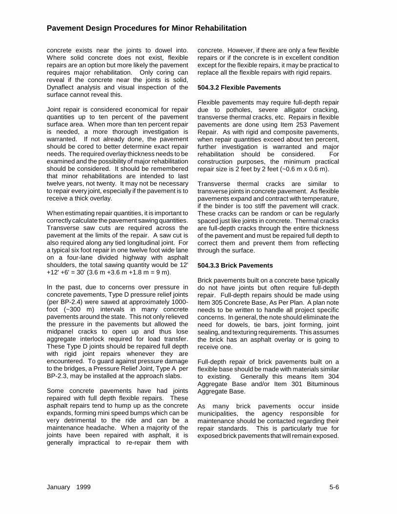
Pavement Design Procedures for Minor Rehabilitation
January 1999 5-6
concrete exists near the joints to dowel into.Where solid concrete does not exist, flexiblerepairs are an option but more likely the pavementrequires major rehabilitation. Only coring canreveal if the concrete near the joints is solid,Dynaflect analysis and visual inspection of thesurface cannot reveal this.
Joint repair is considered economical for repairquantities up to ten percent of the pavementsurface area. When more than ten percent repairis needed, a more thorough investigation iswarranted. If not already done, the pavementshould be cored to better determine exact repairneeds. The required overlay thickness needs to beexamined and the possibility of major rehabilitationshould be considered. It should be rememberedthat minor rehabilitations are intended to lasttwelve years, not twenty. It may not be necessaryto repair every joint, especially if the pavement is toreceive a thick overlay.
When estimating repair quantities, it is important tocorrectly calculate the pavement sawing quantities.Transverse saw cuts are required across thepavement at the limits of the repair. A saw cut isalso required along any tied longitudinal joint. Fora typical six foot repair in one twelve foot wide laneon a four-lane divided highway with asphaltshoulders, the total sawing quantity would be 12'+12' +6' = 30' (3.6 m +3.6 m +1.8 m = 9 m).
In the past, due to concerns over pressure inconcrete pavements, Type D pressure relief joints(per BP-2.4) were sawed at approximately 1000-foot (~300 m) intervals in many concretepavements around the state. This not only relievedthe pressure in the pavements but allowed themidpanel cracks to open up and thus loseaggregate interlock required for load transfer.These Type D joints should be repaired full depthwith rigid joint repairs whenever they areencountered. To guard against pressure damageto the bridges, a Pressure Relief Joint, Type A perBP-2.3, may be installed at the approach slabs.
Some concrete pavements have had jointsrepaired with full depth flexible repairs. Theseasphalt repairs tend to hump up as the concreteexpands, forming mini speed bumps which can bevery detrimental to the ride and can be amaintenance headache. When a majority of thejoints have been repaired with asphalt, it isgenerally impractical to re-repair them with
concrete. However, if there are only a few flexiblerepairs or if the concrete is in excellent conditionexcept for the flexible repairs, it may be practical toreplace all the flexible repairs with rigid repairs.
504.3.2 Flexible Pavements
Flexible pavements may require full-depth repairdue to potholes, severe alligator cracking,transverse thermal cracks, etc. Repairs in flexiblepavements are done using Item 253 PavementRepair. As with rigid and composite pavements,when repair quantities exceed about ten percent,further investigation is warranted and majorrehabilitation should be considered. Forconstruction purposes, the minimum practicalrepair size is 2 feet by 2 feet (~0.6 m x 0.6 m).
Transverse thermal cracks are similar totransverse joints in concrete pavement. As flexiblepavements expand and contract with temperature,if the binder is too stiff the pavement will crack.These cracks can be random or can be regularlyspaced just like joints in concrete. Thermal cracksare full-depth cracks through the entire thicknessof the pavement and must be repaired full depth tocorrect them and prevent them from reflectingthrough the surface.
504.3.3 Brick Pavements
Brick pavements built on a concrete base typicallydo not have joints but often require full-depthrepair. Full-depth repairs should be made usingItem 305 Concrete Base, As Per Plan. A plan noteneeds to be written to handle all project specificconcerns. In general, the note should eliminate theneed for dowels, tie bars, joint forming, jointsealing, and texturing requirements. This assumesthe brick has an asphalt overlay or is going toreceive one.
Full-depth repair of brick pavements built on aflexible base should be made with materials similarto existing. Generally this means Item 304Aggregate Base and/or Item 301 BituminousAggregate Base.
As many brick pavements occur insidemunicipalities, the agency responsible formaintenance should be contacted regarding theirrepair standards. This is particularly true forexposed brick pavements that will remain exposed.
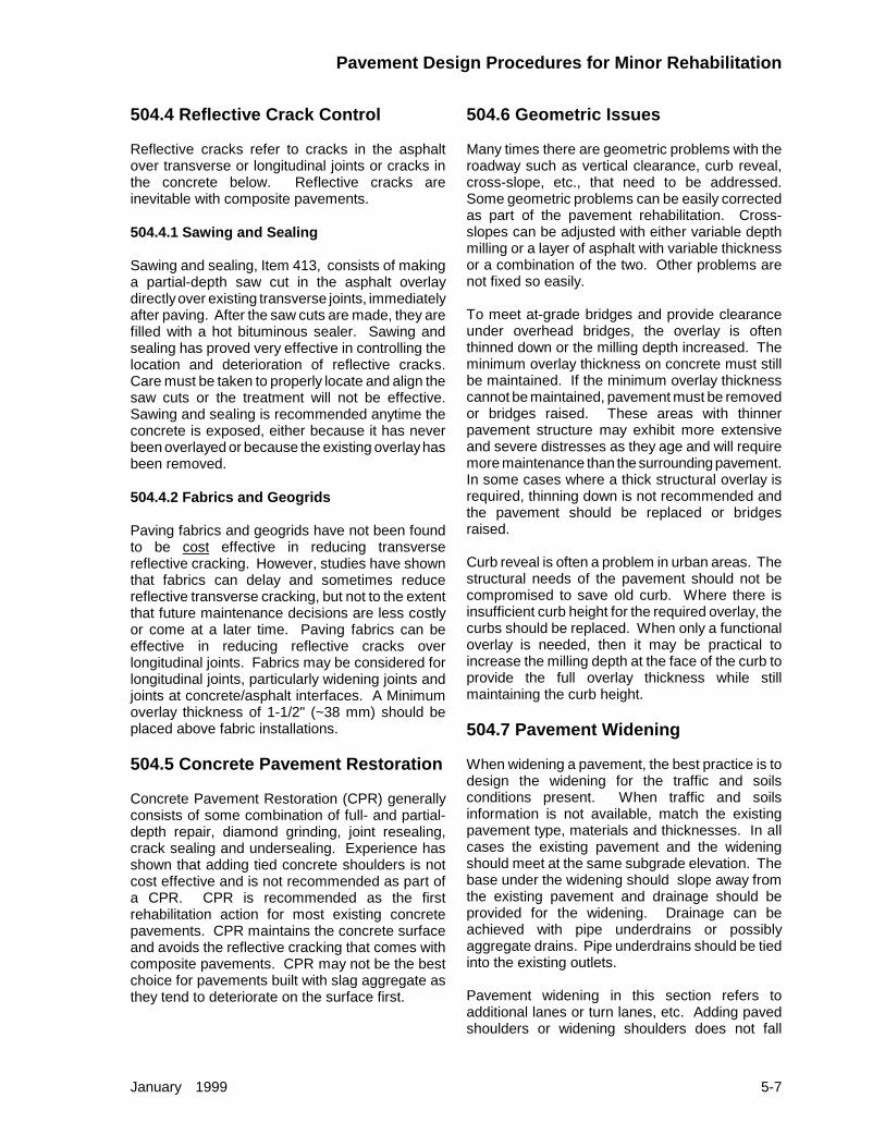
Pavement Design Procedures for Minor Rehabilitation
January 1999 5-7
504.4 Reflective Crack Control
Reflective cracks refer to cracks in the asphaltover transverse or longitudinal joints or cracks inthe concrete below. Reflective cracks areinevitable with composite pavements.
504.4.1 Sawing and Sealing
Sawing and sealing, Item 413, consists of makinga partial-depth saw cut in the asphalt overlaydirectly over existing transverse joints, immediatelyafter paving. After the saw cuts are made, they arefilled with a hot bituminous sealer. Sawing andsealing has proved very effective in controlling thelocation and deterioration of reflective cracks.Care must be taken to properly locate and align thesaw cuts or the treatment will not be effective.Sawing and sealing is recommended anytime theconcrete is exposed, either because it has neverbeen overlayed or because the existing overlay hasbeen removed.
504.4.2 Fabrics and Geogrids
Paving fabrics and geogrids have not been foundto be cost effective in reducing transversereflective cracking. However, studies have shownthat fabrics can delay and sometimes reducereflective transverse cracking, but not to the extentthat future maintenance decisions are less costlyor come at a later time. Paving fabrics can beeffective in reducing reflective cracks overlongitudinal joints. Fabrics may be considered forlongitudinal joints, particularly widening joints andjoints at concrete/asphalt interfaces. A Minimumoverlay thickness of 1-1/2" (~38 mm) should beplaced above fabric installations.
504.5 Concrete Pavement Restoration
Concrete Pavement Restoration (CPR) generallyconsists of some combination of full- and partial-depth repair, diamond grinding, joint resealing,crack sealing and undersealing. Experience hasshown that adding tied concrete shoulders is notcost effective and is not recommended as part ofa CPR. CPR is recommended as the firstrehabilitation action for most existing concretepavements. CPR maintains the concrete surfaceand avoids the reflective cracking that comes withcomposite pavements. CPR may not be the bestchoice for pavements built with slag aggregate asthey tend to deteriorate on the surface first.
504.6 Geometric Issues
Many times there are geometric problems with theroadway such as vertical clearance, curb reveal,cross-slope, etc., that need to be addressed.Some geometric problems can be easily correctedas part of the pavement rehabilitation. Cross-slopes can be adjusted with either variable depthmilling or a layer of asphalt with variable thicknessor a combination of the two. Other problems arenot fixed so easily.
To meet at-grade bridges and provide clearanceunder overhead bridges, the overlay is oftenthinned down or the milling depth increased. Theminimum overlay thickness on concrete must stillbe maintained. If the minimum overlay thicknesscannot be maintained, pavement must be removedor bridges raised. These areas with thinnerpavement structure may exhibit more extensiveand severe distresses as they age and will requiremore maintenance than the surrounding pavement.In some cases where a thick structural overlay isrequired, thinning down is not recommended andthe pavement should be replaced or bridgesraised.
Curb reveal is often a problem in urban areas. Thestructural needs of the pavement should not becompromised to save old curb. Where there isinsufficient curb height for the required overlay, thecurbs should be replaced. When only a functionaloverlay is needed, then it may be practical toincrease the milling depth at the face of the curb toprovide the full overlay thickness while stillmaintaining the curb height.
504.7 Pavement Widening
When widening a pavement, the best practice is todesign the widening for the traffic and soilsconditions present. When traffic and soilsinformation is not available, match the existingpavement type, materials and thicknesses. In allcases the existing pavement and the wideningshould meet at the same subgrade elevation. Thebase under the widening should slope away fromthe existing pavement and drainage should beprovided for the widening. Drainage can beachieved with pipe underdrains or possiblyaggregate drains. Pipe underdrains should be tiedinto the existing outlets.
Pavement widening in this section refers toadditional lanes or turn lanes, etc. Adding pavedshoulders or widening shoulders does not fall

Pavement Design Procedures for Minor Rehabilitation
January 1999 5-8
under this definition. Rebuilt or widened shouldersshould generally use asphalt. Widening projects inexcess of four lane-miles must follow thePavement Design and Selection Process.
504.7.1 Rigid Pavement
When widening existing rigid pavement withconcrete, the new pavement should be the sametype as the old (plain or reinforced) and should betied to the existing concrete using a Type DLongitudinal Joint per BP-2.1. Prior to specifying aType D joint, the existing concrete should be coredto determine soundness. Where coring disclosesunsound pavement; pavement repair, pavementreplacement, or the elimination of the Type D jointshould be considered. Widening of concretepavement without tying longitudinally may createseparation and/or faulting depending on traffic.
The most important consideration when wideningand tying rigid pavement is that transverse joints inthe widening must be of the same type, placed atthe same location, and in the same alignment asthe existing. Mismatched transverse joints willinduce cracking. Longitudinal joints are bestlocated at lane lines. The worst location for alongitudinal joint is in the wheel path. If necessary,remove part of the existing pavement to preventlocating a longitudinal joint in the wheel path.
Rigid pavements which are to be overlayed as partof the widening project should be consideredcomposite pavements and follow the wideningguidelines given in Section 504.7.3.
When widening a rigid pavement with anotherpavement type, the widening should be designedfor the conditions at hand. If necessary, the baseunder the widening should be thickened so that thesubgrade elevations will match. If the widening isthicker than the existing, the subgrade should besloped away from the existing and drainageprovided.
504.7.2 Flexible Pavement
When widening existing flexible pavement withasphalt, the best practice is to make a saw cut atthe edge of a lane and remove the outside edge of
the existing asphalt. This not only removes theuncompacted asphalt at the edges, but ensuresthere will not be a longitudinal construction joint inthe wheel path. When matching thickness with theexisting, the exact buildup and lift thicknessesshould follow the guidelines given in Section 404.
When widening a flexible pavement with anotherpavement type, the widening should be designedfor the conditions at hand. If necessary, the baseunder the widening should be thickened so that thesubgrade elevations will match. If the widening isthicker than the existing the subgrade should besloped away from the existing and drainageprovided.
504.7.3 Composite Pavement
When widening existing composite pavement withcomposite pavement, not only should the subgradeelevations match but the surface of the concretemust match as well. Because it will be overlayedimmediately, use Item 305 Concrete Base for theconcrete regardless what type the existingconcrete is. However, if the existing concrete isreinforced, add a note requiring the 305 also bereinforced. Transverse joints should be the samelocation, alignment and type as the existing.Mismatched transverse joints will induce cracking.Tie the 305 to the existing concrete using a Type DLongitudinal Joint per BP-2.5. Prior to specifying aType D joint, the existing concrete should be coredto determine soundness. If the existing concrete istoo deteriorated at the edge, the widening shouldnot be tied but simply butted up against. Thelongitudinal joint between the old and new concreteis best located at a lane line. It is recommendedthat some of the existing pavement be removedrather than placing the longitudinal joint in a wheelpath.
When widening a composite pavement withanother pavement type, the widening should bedesigned for the conditions at hand. If necessary,the base under the widening should be thickenedso that the subgrade elevations will match. If thewidening is thicker than the existing the subgradeshould be sloped away from the existing anddrainage provided.

500 Pavement Design Procedures for Minor Rehabilitation
List of Figures
Figure Date Subject503-1 January 1999 UTOVER Design Inputs

UTOVER Design Inputs503-1
January 1999
Reference Section503
Parameter Default Value Recommended Value
Reliability - All none see Figure 201-1
Standard Deviation of Traffic - All 0.10 0.10
Poisson’s Ratio - Concrete 0.15 0.15
Poisson’s Ratio - Asphalt 0.35 0.35
Elastic Modulus - Concrete 5,000,000 5,000,000
Resilient Modulus - Asphalt 450,000 450,000
Initial PSI - All 4.5* 4.5
Terminal PSI - All 2.5 2.5
Modulus of Rupture - Concrete 700 700
Load Transfer Coefficient - Concrete 3.2 See below
Drainage Coefficient - Concrete 1.0 1.0
* Early versions of UTOVER list 4.2 as the default Initial PSI when analyzing Flexible pavements.
Load Transfer Coefficient (J)Existing Pavement Edge Support** No Edge Support
Jointed Doweled 2.8 3.2
Jointed Undoweled 3.8 4.2
Continuously Reinforced 2.4 2.8
** Edge support includes tied concrete shoulders, integral curb, widened lane, etc. Widened lanerefers to concrete slabs built 14 feet (~4.2 m) wide or wider, but striped for a standard 12-foot (~3.6 m)lane, leaving 2 feet (~0.6 m) outside the traveled lane to provide edge support.

Table of Contents
600 Major Rehabilitation Design 6-1600.1 Introduction . . . . . . . . . . . . . . . . . . . . . . . . . . . . . . . . . . . . . . . . . . . . . . . . . . 6-1600.2 Subgrade Determination . . . . . . . . . . . . . . . . . . . . . . . . . . . . . . . . . . . . . . . . 6-1
601 Unbonded Concrete Overlay 6-1
602 Fractured Slab Techniques 6-2602.1 Crack & Seat . . . . . . . . . . . . . . . . . . . . . . . . . . . . . . . . . . . . . . . . . . . . . . . . . 6-2602.2 Rubblize & Roll . . . . . . . . . . . . . . . . . . . . . . . . . . . . . . . . . . . . . . . . . . . . . . . 6-2
603 Whitetopping 6-3

January 1999 6-1
600 Major Rehabilitation Design600.1 Introduction
Major rehabilitations are performed when thepavement condition is such that minor rehabilitationis no longer feasible. The Pavement Design andSelection Process, Appendix A, requires majorrehabilitation when the PCR falls below 55. Minorrehabilitation projects may be bumped up to majorbecause of specific conditions on the project. Forexample, project level analysis may revealexcessive repair quantities which make minorrehabilitation a poor choice economically.
Major rehabilitations are designed for twenty-yeartraffic projections using the ESAL99 procedure. Allmajor rehabilitations require a life-cycle costanalysis using the procedures in Section 700.Major rehabilitations include the techniques givenhere, as well as complete removal of the existingpavement and replacement with either concrete orasphalt. The design of new concrete and asphaltis given in Sections 300 and 400.
600.2 Subgrade Determination
To design all major rehabilitations, includingcomplete replacement, it is necessary to know thestrength of the subgrade under the existingpavement. Subgrade strength can be estimatedfrom historical subsurface investigations or byusing the w5 sensor readings from the Dynaflect.The chart in Figure 203-3 shows the relationshipbetween the w5 readings and CBR. The chart usesthe average w5 reading plus two standarddeviations. This information is shown on theDynaflect printout for each direction tested.
Once a major rehabilitation strategy is selected,additional soils investigation may be necessary.For all projects selected for complete replacementor rubblize and roll, soil borings or a soils profile ishighly recommended. Projects selected forunbonded concrete overlay do not requireadditional soils information except possibly in areaswhere the pavement is being replaced because ofbridges, etc. Projects selected for crack and seatgenerally do not need additional soils informationbut if the designer suspects soft subgrade it shouldbe investigated as it can cause problems.
When additional soils information is received andreviewed, the pavement design should be checkedfor adequacy. If the actual subgrade conditions are
different from what was estimated, the pavementdesign may have to be adjusted. Local areas ofweak or wet subgrade should be consideredunsuitable subgrade soil and treated per therecommendations in Section 203.4.1.
601 Unbonded Concrete OverlayAn unbonded concrete overlay is a new concretepavement placed on top of an old, deterioratedconcrete pavement with a thin layer of asphalt inbetween to act as a bond-breaker. The thicknessof an unbonded concrete overlay is derived fromthe required thickness for a new concretepavement reduced by an amount based on theeffective thickness of the existing concrete.
The design of an unbonded concrete overlaybegins with the design of a new rigid pavementaccording to the procedures in Section 300. Nextan asphalt overlay is designed using the UTOVERcomputer program and the procedures given inSection 500. The equation for determining thethickness of an unbonded concrete overlay,developed by the U.S. Army Corps of Engineers, isgiven below:
( ) ( )T T TUCO N E= −2 2
where:
TUCO = Required thickness of theunbonded concrete overlay.
TN = Required thickness for a newconcrete pavement.
TE = Effective thickness of the existingconcrete.
The effective thickness of the existing concretecomes from the UTOVER printout. The columnlabeled “Deff (PCC)” must be manually averagedto find the effective thickness of the existingconcrete. Best practice dictates averaging all thereadings for the entire project, both directions,rather than averaging each direction separatelyand using the smaller or larger number. Thedesign period used in the UTOVER analysis doesnot need to be twenty years as the Deff (PCC)does not change with different traffic inputs. Anexample of an unbonded concrete overlay designis given in Figures 601-1 and 601-2.
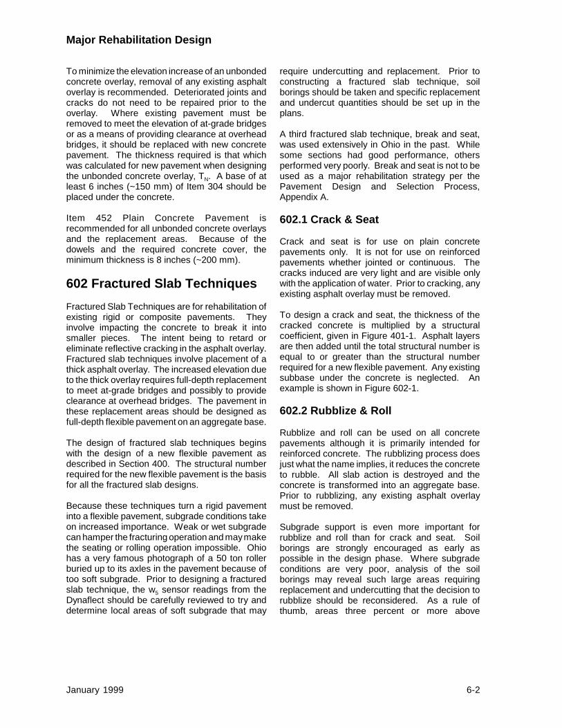
Major Rehabilitation Design
January 1999 6-2
To minimize the elevation increase of an unbondedconcrete overlay, removal of any existing asphaltoverlay is recommended. Deteriorated joints andcracks do not need to be repaired prior to theoverlay. Where existing pavement must beremoved to meet the elevation of at-grade bridgesor as a means of providing clearance at overheadbridges, it should be replaced with new concretepavement. The thickness required is that whichwas calculated for new pavement when designingthe unbonded concrete overlay, TN. A base of atleast 6 inches (~150 mm) of Item 304 should beplaced under the concrete.
Item 452 Plain Concrete Pavement isrecommended for all unbonded concrete overlaysand the replacement areas. Because of thedowels and the required concrete cover, theminimum thickness is 8 inches (~200 mm).
602 Fractured Slab TechniquesFractured Slab Techniques are for rehabilitation ofexisting rigid or composite pavements. Theyinvolve impacting the concrete to break it intosmaller pieces. The intent being to retard oreliminate reflective cracking in the asphalt overlay.Fractured slab techniques involve placement of athick asphalt overlay. The increased elevation dueto the thick overlay requires full-depth replacementto meet at-grade bridges and possibly to provideclearance at overhead bridges. The pavement inthese replacement areas should be designed asfull-depth flexible pavement on an aggregate base.
The design of fractured slab techniques beginswith the design of a new flexible pavement asdescribed in Section 400. The structural numberrequired for the new flexible pavement is the basisfor all the fractured slab designs.
Because these techniques turn a rigid pavementinto a flexible pavement, subgrade conditions takeon increased importance. Weak or wet subgradecan hamper the fracturing operation and may makethe seating or rolling operation impossible. Ohiohas a very famous photograph of a 50 ton rollerburied up to its axles in the pavement because oftoo soft subgrade. Prior to designing a fracturedslab technique, the w5 sensor readings from theDynaflect should be carefully reviewed to try anddetermine local areas of soft subgrade that may
require undercutting and replacement. Prior toconstructing a fractured slab technique, soilborings should be taken and specific replacementand undercut quantities should be set up in theplans.
A third fractured slab technique, break and seat,was used extensively in Ohio in the past. Whilesome sections had good performance, othersperformed very poorly. Break and seat is not to beused as a major rehabilitation strategy per thePavement Design and Selection Process,Appendix A.
602.1 Crack & Seat
Crack and seat is for use on plain concretepavements only. It is not for use on reinforcedpavements whether jointed or continuous. Thecracks induced are very light and are visible onlywith the application of water. Prior to cracking, anyexisting asphalt overlay must be removed.
To design a crack and seat, the thickness of thecracked concrete is multiplied by a structuralcoefficient, given in Figure 401-1. Asphalt layersare then added until the total structural number isequal to or greater than the structural numberrequired for a new flexible pavement. Any existingsubbase under the concrete is neglected. Anexample is shown in Figure 602-1.
602.2 Rubblize & Roll
Rubblize and roll can be used on all concretepavements although it is primarily intended forreinforced concrete. The rubblizing process doesjust what the name implies, it reduces the concreteto rubble. All slab action is destroyed and theconcrete is transformed into an aggregate base.Prior to rubblizing, any existing asphalt overlaymust be removed.
Subgrade support is even more important forrubblize and roll than for crack and seat. Soilborings are strongly encouraged as early aspossible in the design phase. Where subgradeconditions are very poor, analysis of the soilborings may reveal such large areas requiringreplacement and undercutting that the decision torubblize should be reconsidered. As a rule ofthumb, areas three percent or more above

Major Rehabilitation Design
January 1999 6-3
optimum water content will require undercuttingand replacement. Another rule of thumb wasdeveloped to estimate optimum water content: theoptimum water content is the Plastic Limit minusfour. Plastic Limit is not to be confused with thePlasticity Index. The Plastic Limit is equal to theLiquid Limit minus the Plasticity Index.
To design a rubblize and roll, the thickness of therubblized concrete is multiplied by a structuralcoefficient, given in Figure 401-1. Asphalt layersare then added until the total structural number isequal to or greater than the structural numberrequired for a new flexible pavement. Any existingsubbase under the concrete is neglected. Anexample is shown in Figure 602-1.
603 WhitetoppingWhitetopping is the construction of a new rigidpavement on top of an existing asphalt pavement.It is not to be confused with ultra-thin whitetoppingwhich is a thin layer of concrete placed on top ofasphalt to prevent rutting and shoving.Whitetopping is designed as a new rigid pavementusing the existing asphalt pavement as the basefor determining the modulus of subgrade reaction.

600 Major Rehabilitation Design
List of Figures
Figure Date Subject601-1 January 1999 Unbonded Concrete Overlay Example
601-2 January 1999 UTOVER Output (Modified)
602-1 January 1999 Fractured Slab Examples
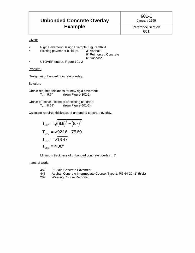
Unbonded Concrete OverlayExample
601-1January 1999
Reference Section601
Given:
• Rigid Pavement Design Example, Figure 302-1• Existing pavement buildup: 3" Asphalt
9" Reinforced Concrete6" Subbase
• UTOVER output, Figure 601-2
Problem:
Design an unbonded concrete overlay.
Solution:
Obtain required thickness for new rigid pavement.TN = 9.6" (from Figure 302-1)
Obtain effective thickness of existing concrete.TE = 8.69" (from Figure 601-2)
Calculate required thickness of unbonded concrete overlay.
( ) ( )T
T
TT
UCO
UCO
UCO
UCO
= −
= −
==
9 6 87
9216 75 69
16 47406
2 2. .
. .
.. "
Minimum thickness of unbonded concrete overlay = 8"
Items of work:
452 8" Plain Concrete Pavement448 Asphalt Concrete Intermediate Course, Type 1, PG 64-22 (1" thick)202 Wearing Course Removed
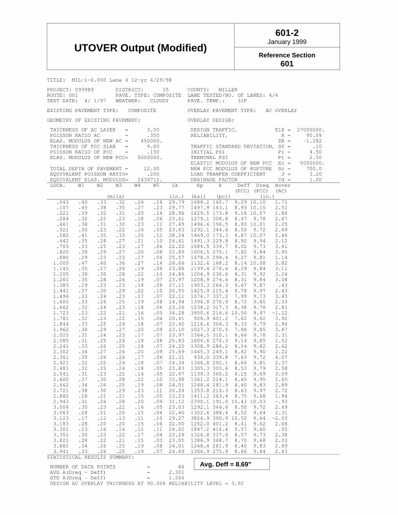
UTOVER Output (Modified)601-2
January 1999
Reference Section601
TITLE: MIL-1-0.000 Lane 4 12-yr 4/29/98
PROJECT: 099989 DISTRICT: 15 COUNTY: MILLERROUTE: 001 PAVE. TYPE: COMPOSITE LANE TESTED/NO. OF LANES: 4/4TEST DATE: 4/ 1/97 WEATHER: CLOUDY PAVE. TEMP.: 31F
EXISTING PAVEMENT TYPE: COMPOSITE OVERLAY PAVEMENT TYPE: AC OVERLAY
GEOMETRY OF EXISTING PAVEMENT: OVERLAY DESIGN:
THICKNESS OF AC LAYER = 3.00 DESIGN TRAFFIC, E18 = 27000000. POISSON RATIO AC = .350 RELIABILITY, R = 90.0% ELAS. MODULUS OF NEW AC = 450000. ZR = -1.282 THICKNESS OF PCC SLAB = 9.00 TRAFFIC STANDARD DEVIATION, S0 = .10 POISSON RATIO OF PCC = .150 INITIAL PSI Pi = 4.50 ELAS. MODULUS OF NEW PCC= 5000000. TERMINAL PSI Pt = 2.50
ELASTIC MODULUS OF NEW PCC Ec = 5000000. TOTAL DEPTH OF PAVEMENT = 12.00 NEW PCC MODULUS OF RUPTURE Sc = 700.0 EQUIVALENT POISSON RATIO= .200 LOAD TRANFER COEFFICIENT J = 3.20 EQUIVALENT ELAS. MODULUS= 2436712. DRAINAGE FACTOR Cd = 1.00 LOCA. W1 W2 W3 W4 W5 Lk Ep k Deff Dreq Hover (PCC) (PCC) (AC) (mils) (in.) (ksi) (pci) (in.) .043 .40 .33 .32 .26 .16 29.79 1688.2 160.7 9.29 10.10 1.71 .107 .45 .38 .35 .27 .23 29.77 1497.9 143.1 8.93 10.15 2.51 .221 .39 .32 .31 .25 .14 28.96 1629.5 173.8 9.18 10.07 1.86 .284 .32 .25 .23 .18 .06 23.61 1279.1 308.8 8.47 9.78 2.67 .461 .38 .31 .30 .23 .12 27.49 1496.6 196.5 8.93 10.01 2.25 .521 .30 .23 .22 .16 .05 23.03 1292.1 344.6 8.50 9.72 2.49 .582 .41 .35 .33 .25 .12 28.24 1469.0 173.3 8.87 10.07 2.46 .642 .35 .28 .27 .21 .10 26.41 1491.3 229.8 8.92 9.94 2.12 .703 .33 .25 .23 .17 .06 22.20 1084.5 334.7 8.02 9.73 3.41 .820 .38 .29 .27 .20 .08 22.89 1006.5 275.1 7.82 9.84 3.95 .880 .29 .23 .23 .17 .06 25.57 1678.0 294.4 9.27 9.81 1.14 1.005 .47 .40 .36 .27 .14 26.66 1132.6 168.2 8.14 10.08 3.82 1.145 .35 .27 .26 .19 .08 23.88 1199.4 276.4 8.29 9.84 3.11 1.205 .38 .30 .28 .22 .10 24.86 1204.9 236.6 8.31 9.92 3.24 1.261 .35 .28 .26 .19 .07 23.97 1208.9 274.6 8.31 9.84 3.08 1.383 .29 .23 .23 .18 .08 27.11 1903.3 264.3 9.67 9.87 .43 1.441 .37 .30 .29 .22 .10 26.55 1425.9 215.4 8.78 9.97 2.43 1.496 .33 .24 .23 .17 .07 22.11 1074.7 337.2 7.99 9.73 3.45 1.605 .33 .26 .25 .19 .08 24.94 1396.8 270.9 8.72 9.85 2.33 1.662 .32 .24 .23 .18 .06 23.26 1238.2 317.3 8.38 9.76 2.81 1.723 .23 .22 .21 .16 .05 34.28 3950.6 214.6 10.50 9.97 -1.22 1.781 .32 .23 .22 .15 .04 20.41 928.9 401.2 7.62 9.62 3.92 1.844 .33 .25 .24 .18 .07 23.40 1216.6 304.3 8.33 9.79 2.94 1.962 .38 .29 .27 .20 .09 23.10 1027.3 270.5 7.88 9.85 3.87 2.025 .31 .24 .23 .17 .07 23.97 1364.5 310.1 8.66 9.78 2.31 2.085 .31 .25 .24 .18 .08 25.83 1604.6 270.3 9.14 9.85 1.52 2.241 .33 .26 .25 .18 .07 24.20 1308.9 286.2 8.54 9.82 2.62 2.302 .34 .27 .26 .20 .09 25.69 1445.3 249.1 8.82 9.90 2.22 2.361 .35 .26 .24 .17 .06 21.31 934.0 339.8 7.63 9.72 4.07 2.421 .32 .25 .24 .18 .07 24.34 1366.8 292.1 8.66 9.81 2.37 2.481 .32 .25 .24 .18 .05 23.83 1305.3 303.6 8.53 9.79 2.58 2.541 .31 .23 .22 .16 .05 22.07 1139.3 360.2 8.15 9.69 3.09 2.600 .37 .30 .28 .22 .10 25.98 1361.2 224.1 8.65 9.95 2.65 2.662 .34 .26 .25 .19 .08 24.01 1248.4 281.9 8.40 9.83 2.89 2.721 .38 .30 .29 .23 .11 26.24 1353.8 214.3 8.63 9.97 2.72 2.882 .28 .21 .21 .15 .05 23.23 1411.2 363.4 8.75 9.68 1.94 2.943 .31 .26 .28 .20 .09 31.12 2390.1 191.0 10.43 10.03 -.93 3.004 .30 .23 .22 .16 .05 23.03 1292.1 344.6 8.50 9.72 2.49 3.063 .28 .21 .20 .15 .04 22.40 1302.6 388.4 8.52 9.64 2.31 3.123 .17 .12 .13 .11 .10 29.27 3824.9 390.9 10.50 9.64 -2.03 3.183 .28 .20 .20 .15 .04 22.00 1252.0 401.2 8.41 9.62 2.48 3.301 .23 .16 .16 .12 .11 24.02 1847.2 416.4 9.57 9.60 .05 3.351 .30 .23 .22 .17 .04 23.29 1324.8 337.6 8.57 9.73 2.38 3.821 .28 .22 .21 .15 .03 23.05 1386.9 368.7 8.70 9.68 2.03 3.882 .34 .26 .25 .19 .08 24.01 1248.4 281.9 8.40 9.83 2.89 3.941 .33 .26 .25 .19 .07 24.69 1366.9 275.9 8.66 9.84 2.43STATISTICAL RESULTS SUMMARY:
NUMBER OF DATA POINTS = 46 AVG A(Dreq - Deff) = 2.301 STD A(Dreq - Deff) = 1.266 DESIGN AC OVERLAY THICKNESS AT 90.00% RELIABILITY LEVEL = 3.92
Avg. Deff = 8.69"

Fractured Slab Examples602-1
January 1999
Reference Section602
Crack & Seat Example
Given:
• Flexible Pavement Design Example, Figure 402-1• Existing pavement buildup: 3" Asphalt
8" Item 305 Concrete Base6" Subbase
Problem:
Design a Crack & Seat project.
Solution:
Obtain required structural number for a new flexible pavementSN = 4.5 (from Figure 402-1)
Determine the required buildup using the structural coefficients given in Figure 401-1
Material Thickness Coefficient SN446 Surface 1.5" x 0.35 = 0.52446 Intermediate 1.75" x 0.35 = 0.61301 4" x 0.35 = 1.40305 (cracked & seated) 8" x 0.27 = 2.16
Total Structural Number = 4.69
Rubblize & Roll Example
Given:
• Flexible Pavement Design Example, Figure 402-1.• Existing Pavement Buildup: 4" Asphalt
9" Reinforced Concrete6" Subbase
Problem:
Design a Rubblize & Roll project.
Solution:
Obtain required structural number for a new flexible pavement.SN = 4.5 (from Figure 402-1)
Determine the required buildup using the structural coefficients given in Figure 401-1.
Material Thickness Coefficient SN446 Surface 1.5" x 0.35 = 0.52446 Intermediate 2" x 0.35 = 0.70302 6" x 0.35 = 2.10Rubblized Concrete 9" x 0.14 = 1.26
Total Structural Number = 4.58
Table of Contents
700 Life-Cycle Cost Analysis 7-1700.1 Introduction . . . . . . . . . . . . . . . . . . . . . . . . . . . . . . . . . . . . . . . . . . . . . . . . . . 7-1
700.1.1 Alternatives Considered . . . . . . . . . . . . . . . . . . . . . . . . . . . . . . . . . 7-1700.1.2 Analysis Period . . . . . . . . . . . . . . . . . . . . . . . . . . . . . . . . . . . . . . . 7-1700.1.3 Estimated Prices . . . . . . . . . . . . . . . . . . . . . . . . . . . . . . . . . . . . . . 7-1700.1.4 Discount Rate . . . . . . . . . . . . . . . . . . . . . . . . . . . . . . . . . . . . . . . . 7-1
701 Initial Construction 7-1
702 Future Maintenance 7-2702.1 Introduction . . . . . . . . . . . . . . . . . . . . . . . . . . . . . . . . . . . . . . . . . . . . . . . . . . 7-2702.2 Maintenance Schedules . . . . . . . . . . . . . . . . . . . . . . . . . . . . . . . . . . . . . . . . 7-2
702.2.1 Flexible Pavement . . . . . . . . . . . . . . . . . . . . . . . . . . . . . . . . . . . . . 7-2702.2.2 Rigid Pavement . . . . . . . . . . . . . . . . . . . . . . . . . . . . . . . . . . . . . . . 7-3702.2.3 Composite Pavement . . . . . . . . . . . . . . . . . . . . . . . . . . . . . . . . . . 7-3702.2.4 Unbonded Concrete Overlay . . . . . . . . . . . . . . . . . . . . . . . . . . . . . 7-3702.2.5 Fractured Slab Techniques . . . . . . . . . . . . . . . . . . . . . . . . . . . . . . 7-3702.2.6 Whitetopping . . . . . . . . . . . . . . . . . . . . . . . . . . . . . . . . . . . . . . . . . 7-3
703 Total Cost 7-4703.1 Discounting . . . . . . . . . . . . . . . . . . . . . . . . . . . . . . . . . . . . . . . . . . . . . . . . . . 7-4
704 Lane Closure Days 7-4
705 Results Presentation 7-4
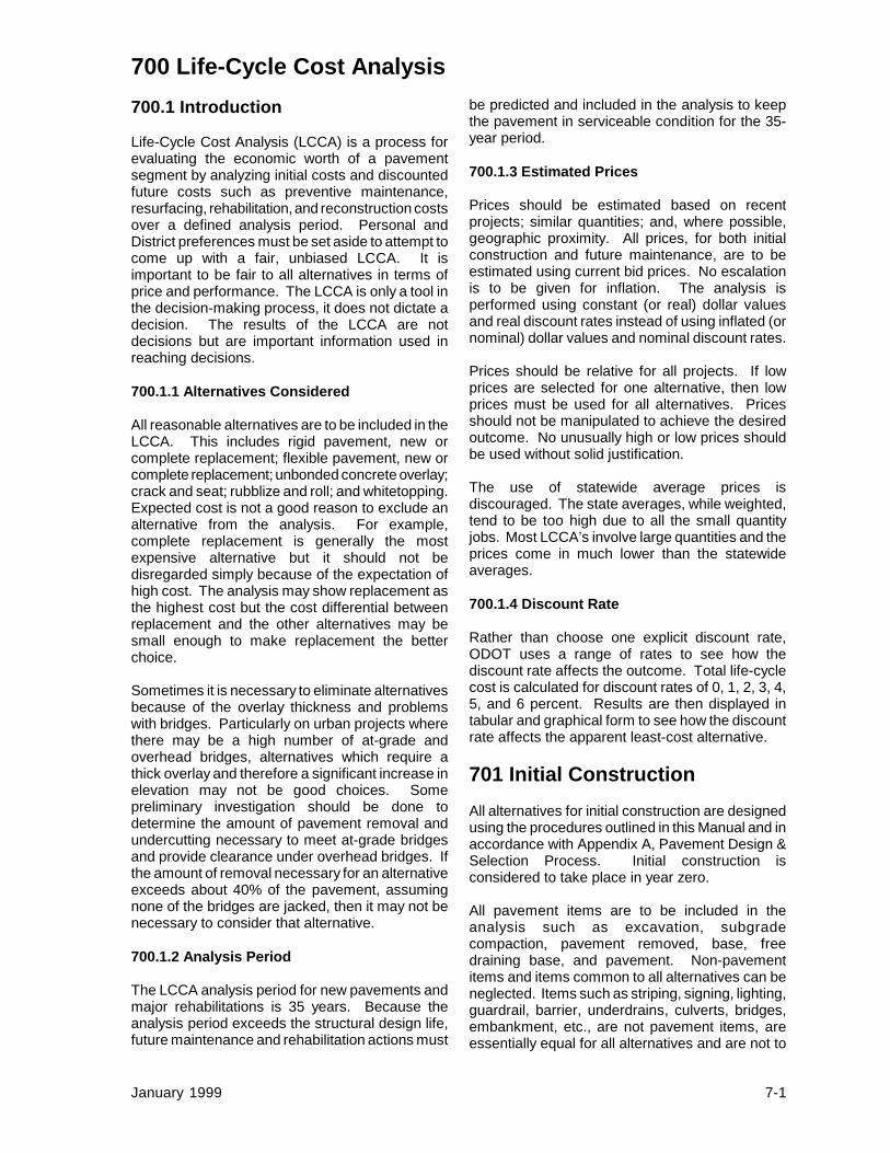
January 1999 7-1
700 Life-Cycle Cost Analysis700.1 Introduction
Life-Cycle Cost Analysis (LCCA) is a process forevaluating the economic worth of a pavementsegment by analyzing initial costs and discountedfuture costs such as preventive maintenance,resurfacing, rehabilitation, and reconstruction costsover a defined analysis period. Personal andDistrict preferences must be set aside to attempt tocome up with a fair, unbiased LCCA. It isimportant to be fair to all alternatives in terms ofprice and performance. The LCCA is only a tool inthe decision-making process, it does not dictate adecision. The results of the LCCA are notdecisions but are important information used inreaching decisions.
700.1.1 Alternatives Considered
All reasonable alternatives are to be included in theLCCA. This includes rigid pavement, new orcomplete replacement; flexible pavement, new orcomplete replacement; unbonded concrete overlay;crack and seat; rubblize and roll; and whitetopping.Expected cost is not a good reason to exclude analternative from the analysis. For example,complete replacement is generally the mostexpensive alternative but it should not bedisregarded simply because of the expectation ofhigh cost. The analysis may show replacement asthe highest cost but the cost differential betweenreplacement and the other alternatives may besmall enough to make replacement the betterchoice.
Sometimes it is necessary to eliminate alternativesbecause of the overlay thickness and problemswith bridges. Particularly on urban projects wherethere may be a high number of at-grade andoverhead bridges, alternatives which require athick overlay and therefore a significant increase inelevation may not be good choices. Somepreliminary investigation should be done todetermine the amount of pavement removal andundercutting necessary to meet at-grade bridgesand provide clearance under overhead bridges. Ifthe amount of removal necessary for an alternativeexceeds about 40% of the pavement, assumingnone of the bridges are jacked, then it may not benecessary to consider that alternative.
700.1.2 Analysis Period
The LCCA analysis period for new pavements andmajor rehabilitations is 35 years. Because theanalysis period exceeds the structural design life,future maintenance and rehabilitation actions must
be predicted and included in the analysis to keepthe pavement in serviceable condition for the 35-year period.
700.1.3 Estimated Prices
Prices should be estimated based on recentprojects; similar quantities; and, where possible,geographic proximity. All prices, for both initialconstruction and future maintenance, are to beestimated using current bid prices. No escalationis to be given for inflation. The analysis isperformed using constant (or real) dollar valuesand real discount rates instead of using inflated (ornominal) dollar values and nominal discount rates.
Prices should be relative for all projects. If lowprices are selected for one alternative, then lowprices must be used for all alternatives. Pricesshould not be manipulated to achieve the desiredoutcome. No unusually high or low prices shouldbe used without solid justification.
The use of statewide average prices isdiscouraged. The state averages, while weighted,tend to be too high due to all the small quantityjobs. Most LCCA’s involve large quantities and theprices come in much lower than the statewideaverages.
700.1.4 Discount Rate
Rather than choose one explicit discount rate,ODOT uses a range of rates to see how thediscount rate affects the outcome. Total life-cyclecost is calculated for discount rates of 0, 1, 2, 3, 4,5, and 6 percent. Results are then displayed intabular and graphical form to see how the discountrate affects the apparent least-cost alternative.
701 Initial ConstructionAll alternatives for initial construction are designedusing the procedures outlined in this Manual and inaccordance with Appendix A, Pavement Design &Selection Process. Initial construction isconsidered to take place in year zero.
All pavement items are to be included in theanalysis such as excavation, subgradecompaction, pavement removed, base, freedraining base, and pavement. Non-pavementitems and items common to all alternatives can beneglected. Items such as striping, signing, lighting,guardrail, barrier, underdrains, culverts, bridges,embankment, etc., are not pavement items, areessentially equal for all alternatives and are not to

Life-Cycle Cost Analysis
January 1999 7-2
be included in the analysis. On new locations,earthwork items including subgrade compactionare common to all pavement alternatives and areessentially equal and therefore do not need to beincluded.
For rehabilitations that raise the elevation of theexisting pavement, a cost needs to be included formaintaining clearance under overhead structuresand for meeting elevations of at-grade bridges.For convenience, this is known as the “cost ofmaintaining clearance”. This cost can becalculated in various ways. One way is to calculatethe cost to remove the existing pavement,excavate down, and build back up with newpavement. Another way is to calculate the cost ofjacking the bridges, including any approach worknecessary on overheads. A third option could bea combination of the two.
It is not important which method is selected forcomputing cost of maintaining clearance. What isimportant is that a dollar amount is included in theanalysis to account for the cost of maintainingclearance. For convenience, it is recommended touse the same method for all alternatives, i.e. do notremove pavement and excavate for the rubblizealternative and then jack bridges for the unbondedconcrete overlay alternative. The method used inthe LCCA for computing cost of maintainingclearance does not have to be the actual methodused in the plans and in construction.
702 Future Maintenance
702.1 Introduction
The future maintenance required to keep thepavement in serviceable condition for the next 35years must be predicted. The number one factorwhen determining required maintenance isengineering judgement. The performanceequations given in Figure 101-2 are usefulguidance. It is important to note the performancebeing predicted is for pavements built to currentspecifications, not 1960's specifications. Manychanges and improvements have been made toboth asphalt and concrete including such things asPG binders, polymers, gradation changes, freedraining bases, epoxy coated steel, non d-crackingaggregates, etc. These changes are expected toresult in improved performance and this improvedperformance should be reflected in the LCCA.
Routine maintenance performed by ODOT forceshas traditionally been ignored due to lack ofdependable data. Only contract maintenance isconsidered.
ODOT does not use salvage value. This meanswhen choosing the maintenance strategies andtiming, the designer must try to balance them suchthat all alternatives are in approximately the samecondition in year 35. Generally the goal is to haveeach alternative require additional maintenancejust after the end of the analysis period. In otherwords, do not place a thick overlay on onealternative in year 32 while doing nothing sinceyear 25 on the other alternatives.
702.2 Maintenance Schedules
The maintenance strategies and schedules givenbelow are for informational purposes only. Thisinformation is intended to give designers somereasonable guidance when deciding themaintenance actions for an LCCA. Wide latitudeis given on both the timing and the work predicted.The designer is not restricted to these schedules;but, because of the wide latitude given, anythingoutside the schedules may be questioned. Allthicknesses given are approximate but overlaysmuch thicker or much thinner than those listed arenot expected.
The schedules list only major items of work. Thedesigner may need to include additional items. Forinstance, tack coats are not listed but are requiredwith all overlays. It is not intended that every itemlisted be used in a given year. For example,concrete pavement shows both an asphalt overlayand diamond grinding as options but never wouldthe two of them be done at the same time. It isfurther not intended that actions must take place inevery one of the years listed. Depending on theexpected performance and the actions predictedfor the early years, the later rehabilitation(s) maynot be necessary.
702.2.1 Flexible Pavement
Flexible pavement includes new pavement on anew alignment and complete replacement ofexisting pavement.
Year 10 - 15: Thin overlay, 1.25" -3" (~32 - 75 mm), with or withoutmilling.

Life-Cycle Cost Analysis
June 1999 7-3
Year 18 - 25: Thick overlay, 3" - 7"(~75 - 175 mm), with milling,possibly pavement repairs.
Year 28 - 32: Thin overlay ormicro-surfacing or crack sealing.
Many times the third treatment would not benecessary at all depending on the timing of the firsttwo and the thickness of the overlays and theirexpected performance.
702.2.2 Rigid Pavement
Rigid pavement includes new pavement on a newalignment and complete replacement of existingpavement. Percentages given are of the totalmainline pavement area not including shoulders orramps or turn lanes, etc.
Year 18 - 25: 2% - 10% full-depthrigid repairs, 1% - 5% partial-depth bonded repairs, diamondgrinding, 3" - 6" (~75 - 150 mm)overlay, sawing and sealing.
Year 28 - 32: 1% - 3% full- and/orpartial-depth repairs, 1.25" - 2"(~32 - 50 mm) second overlaywith or without milling, 3" - 4" (~75- 100 mm) first overlay, sawingand sealing, micro-surfacing,crack sealing, diamond grinding.
Best practice dictates the use of diamond grindingfor the first treatment. Placing an asphalt overlayon a concrete pavement brings on a new set ofproblems and is discouraged as the first predictedmaintenance action. Remember, this is thepredicted performance of pavements built tocurrent specifications, not 1960's specifications.
Again, in many cases the second treatment maynot be necessary at all.
702.2.3 Composite Pavement
Composite pavement is a hybrid of rigid andflexible pavement and requires the maintenanceactions of both. It is generally expected to receivefull-depth rigid repairs, milling and an overlay every8 - 12 years.
702.2.4 Unbonded Concrete Overlay
An unbonded concrete overlay is in essence a newconcrete pavement built on top of the old. It willrequire maintenance similar to that for a rigidpavement. It may be reasonable to expect slightlyless repair for an unbonded concrete overlayversus new rigid pavement due to the much thickerpavement section.
702.2.5 Fractured Slab Techniques
Fractured slab techniques include crack & seat,and rubblize & roll.
Year 8 - 12: Thin overlay, 1.25" -4" (~32 - 100 mm) with or withoutmilling.
Year 16 - 22: Thick overlay, 4" - 8"(~100 - 200 mm) with milling,pavement repair.
Year 24 - 32: Thin overlay, 1.25" -4" (~32 - 100 mm) with or withoutmilling, micro-surfacing, cracksealing.
Fractured slab techniques are more likely torequire the third maintenance action than is flexiblepavement.
702.2.6 Whitetopping
Whitetopping is in essence a new concretepavement built over an existing flexible pavement.It is expected to perform similar to a rigid pavementor an unbonded concrete overlay.

Life-Cycle Cost Analysis
June 1999 7-4
703 Total CostOnce all the costs for initial construction and futuremaintenance have been calculated, they aresummed to determine the net present value ofeach alternative. Future maintenance costs arediscounted which accounts for and the time valueof money.
703.1 Discounting
Discounting is a simple yet effective way toaccount for the time value of money. The discountrate is essentially the difference between marketinterest rates and the general rate of inflation. Forexample, one-year Certificates of Deposit (CD)might be paying 5.5% while inflation is running2.0% per year, the discount rate would be 3.5%.By the same token, if CD’s are paying 8.0% andinflation is running 4.5%, the discount rate is still3.5%. Using a discount rate thus eliminates theneed to predict what inflation will do for the next 35years or what return one might get on aninvestment.
The formula for applying the discount rate is asfollows:
(P/F,i%,n) = ( )1
1+ i n
where:(P/F,i%,n) = discount factori = discount rate (0% to 6%)n = year costs occur
An example showing how to use the discount rateand calculate total cost is given in Figure 703-1.
704 Lane Closure DaysLane closure days is a measure of the impact ofeach alternative on the traveling public. It is not ameasure of the time needed to construct eachalternative. It is merely a comparison tool given astandard work crew, a ten-hour day, a single-laneclosure, etc., of how many days it would take tocomplete each alternative. One lane closure dayequals twenty-four hours that a lane is not availableto traffic even though work is only being performedfor ten hours. The production rates for certain
items which can be opened to traffic uponcompletion of each day’s work have been adjustedto account for the fact the lane is not closedtwenty-four hours.
The production rates used in calculating thenumber of days of lane closure are given in Figure704-1.
705 Results PresentationA great deal of information is contained in theLCCA and the supporting documentation. It isimportant it be presented in a standard format.Examples are given in Figures 705-1 and 705-2.
The first page of the report gives generalinformation about the project and the alternativesand provides space for the members of thePavement Selection Committee to sign off on onealternative. The second page summarizes theDistrict’s selected alternative. This page lists eachof the principal and secondary factors from thePavement Design and Selection Process,Appendix A, and gives justification for the selectedalternative for each factor. Additional pages mayor may not be necessary to give more detailedinformation on the initial buildups, predicted futuremaintenance, widening buildups, etc. One pagegives background information on the projectincluding historical data on the project, the originalconstruction project, all rehabilitations to date, theexisting buildup, etc.; also, the physical attributessuch as interchanges, intersections, overhead andat-grade bridges, etc.; and the condition of theexisting pavement, PCR, traffic, functionalclassification, etc. Next are pages showing thedetails of the LCCA such as items, quantities,prices and costs for initial and future construction.Next, a graph showing how the discount rateaffects the apparent least cost alternative andfinally a page giving the lane closure analysis.
Once all the information is assembled, the DistrictDeputy Director should sign off on one alternative.The package is then sent to the Pavement DesignSection of the Office of Materials Management whowill review the LCCA package for concurrence andthen forward the report to the Pavement SelectionCommittee for approval. The Committee will returnthe signed copy to the Pavement Design Sectionwho will inform the District of the decision andnotify FHWA, if necessary.

700 Life-Cycle Cost Analysis
List of Figures
Figure Date Subject703-1 January 1999 Discounting Example
704-1 January 1999 Lane Closure Days
705-1 January 1999 Rehabilitation Example Page 1
705-1 June 1999 Rehabilitation Example Page 1a
705-1 January 1999 Rehabilitation Example Pages 2 - 11
705-2 June 1999 New Pavement Example Pages 1 - 5

Discounting Example703-1
January 1999
Reference Section703.1
Given:
• Initial Construction (Year 0): $6,500,000 • First Maintenance (Year 12): $800,000 • Second Maintenance (Year 20): $1,600,000 • Third Maintenance (Year 30): $200,000
Problem:
Solve for the net present value using discount rates of 0, 1, 2, 3, 4, 5, and 6%.
Solution:
Calculate the discount factor for each year and discount rate using the equation given in Section703.1.
Rate Year 0 Year 12 Year 20 Year 30
0% 1.0000 1.0000 1.0000 1.0000
1% 1.0000 0.8874 0.8195 0.7419
2% 1.0000 0.7885 0.6730 0.5521
3% 1.0000 0.7014 0.5537 0.4120
4% 1.0000 0.6246 0.4564 0.3083
5% 1.0000 0.5568 0.3769 0.2314
6% 1.0000 0.4970 0.3118 0.1741
Multiply costs by discount factors and sum to find Net Present Value (NPV) at each discount rate.
NPV0% = (6500000)*(1)+(800000)*(1)+(1600000)*(1)+(200000)*(1)= $9,100,000
NPV1% = (6500000)*(1)+(800000)*(0.8874)+(1600000)*(0.8195)+(200000)*(0.7419)= $8,669,500
NPV2% = (6500000)*(1)+(800000)*(0.7885)+(1600000)*(0.6730)+(200000)*(0.5521)= $8,318,020
NPV3% = (6500000)*(1)+(800000)*(0.7014)+(1600000)*(0.5537)+(200000)*(0.4120)= $8,029,440
NPV4% = (6500000)*(1)+(800000)*(0.6246)+(1600000)*(0.4564)+(200000)*(0.3083)= $7,791,580
NPV5% = (6500000)*(1)+(800000)*(0.5568)+(1600000)*(0.3769)+(200000)*(0.2314)= $7,594,760
NPV6% = (6500000)*(1)+(800000)*(0.4970)+(1600000)*(0.3118)+(200000)*(0.1741)= $7,431,300

Lane Closure Days704-1
January 1999
Reference Section704
Item #
---------------
202202202203203203206252252252253254254255255301304305306307407408409413446-1446-2448-1448-2451 & 452451 & 452453SpecialSpecialSpecial450...801
Description
-----------------------------------------------------
Wearing Course RemovedPavement RemovedBase RemovedExcavation not Inc. EmbankmentSubgrade CompactionProof RollingLime Soil Stabilized SubgradePartial Depth Pavement RepairRigid Remove/Flexible ReplacePavement SawingPavement RepairPavement Planing - BituminousPavement Planing - PCCRigid Remove/Rigid Repl. Class CPavement SawingBituminous Aggregate Base (302)Aggregate BaseConcrete BaseCement Treated FDBNon Stabilized Drainage BaseTack CoatBituminous Prime CoatSeal CoatSawing and SealingAC Surface Course, Type 1AC Intermediate Course, Type 2AC Surface Course, Type 1AC Intermediate Course, Type 2Concrete Pavement (MAINLINE)Concrete Pavement (SHOULDERS)CRC PavementAsphalt Treated FDBCracking and SeatingRubblize and RollJoint Clean/Seal - All Types
ENGLISHProd. Rate
-----------------------
11,250 SY/Day12250 SY/Day1000 CY/Day2500 CY/Day1 Day/Lane48,750 SY/Day2125 SY/Day1625 SY/Day1000 SY/Day1 Day/Lane875 CY/Day2,38750 SY/Day48750 SY/Day5875 SY/Day1 Day/Lane875 CY/Day1250 CY/Day52875 SY/Day62875 SY/Day63750 SY/DayNeglectNeglectNeglect1875 LF/Day4,71124 CY/Day3625 CY/Day4,71250 CY/Day3688 CY/Day54750 SY/Day53175 SY/Day51875 SY/Day63125 SY/Day12,500 SY/Day2500 SY/Day413,750 LF/Day +1 Day/ Lane
METRICProd. Rate
------------------------
9406 m2/Day11881 m2/Day765 m3/Day1911 m3/Day1 Day/Lane40,761 m2/Day1776 m2/Day1359 m2/Day836 m2/Day1 Day/Lane669 m3/Day2,37316 m2/Day47316 m2/Day5731 m2/Day1 Day/Lane669 m3/Day956 m3/Day52404 m2/Day62404 m2/Day63135 m2/DayNeglectNeglectNeglect571 m/Day4,7860 m3/Day3478 m3/Day4,7956 m3/Day3526 m3/Day53972 m2/Day52655 m2/Day51568 m2/Day62612 m2/Day10,451 m2/Day2090 m2/Day44190 m/Day +1 Day/Lane

Notes to Lane Closure Days
Figure 704-1
1. For situations where shoulders are being removed for replacement, pavement removal andwearing course removal can be done simultaneously. Only use the greater of the twoquantities depending on the project
2. On future maintenance only, where planing and a one-course overlay are being performed asone continuous operation, such as thin mill and fill jobs often done as night work, theproduction rate for this item should be doubled and the time for the overlay neglected.
3. On future maintenance only, where conditions allow the pavement to be opened to traffic atthe end of each ten hour work day, the production rate for this item should be doubled. Whenthe dropoff between lanes is too large and the pavement cannot be opened to traffic until theitem is completed or other work is being performed which prevents the pavement from beingopened, the given production rate should be used with no doubling.
4. Production rates for these items have been adjusted to reflect the fact that the pavement isopened to traffic during the part of the day when work is not being performed.
5. All concrete pavement items do not include the curing time. The curing time should be addedto the summary where applicable in the final analysis.
Class C - 10 Days/ProjectClass MS - 2 Days/ProjectClass FS - 1 Day/Project
6. Where type is yet to be determined, use 3125 SY/Day (2612 m2/Day).
7. Where Sawing and Sealing is specified, use only 1 Day/Lane for 446-1 or 448-1.

Rehabilitation ExamplePage 1
705-1January 1999
Reference Section705
Pavement Type and Rehabilitation Strategy Approval
Project: ABC-1-8.30 Date: February 29, 1999 Length: 7.84 miles PID No.: 12345 Plans: 20 % complete Program Amount: $25,000,000
• Alternative 1: Rubblize and Roll - Remove the existing asphalt overlay, rubblize the existingconcrete and overlay with 13.5" of asphalt. Twenty-nine percent removal, undercut and replacement isrequired to meet at-grade bridges and provide clearance at overhead bridges, assuming bridges are notjacked.
• Alternative 2: Unbonded Concrete Overlay - Remove the existing asphalt overlay, place a 1"asphalt bondbreaker layer and overlay with 8" of plain concrete. Twenty-two percent removal,undercut and replacement is required to meet at-grade bridges and provide clearance at overheadbridges, assuming bridges are not jacked.
• Alternative 3: Flexible Replacement - Remove the existing pavement and replace with 12.75" ofasphalt on 12" of 304.
• Alternative 4: Rigid Replacement - Remove the existing pavement and replace with 12" ofreinforced concrete on a Free Draining Base on 6" of 304.
PLEASE INDICATE BELOW YOUR APPROVAL OF ONE OF THE ALTERNATIVES THEN RETURNTO MATERIALS MANAGEMENT
Pavement Selection Committee New Design/ Rehabilitation ApprovalAlt. 1 Alt. 2 Alt. 3 Alt. 4
District Deputy Director ______________________________________________
Assistant Director for Transportation Policy ______________________________________________
Assistant Director for Field Operations ______________________________________________
Deputy Director of Engineering Policy ______________________________________________

Rehabilitation ExamplePage 1a
705-1June 1999
Reference Section705
Selection Summary Sheet
Alternative 2, Unbonded Concrete Overlay, has been selected by the District. The following discussionconcerning this selection is provided in an effort to communicate the rational for this decision.
Principal Factors
LCCA: The Unbonded Concrete Overlay has the lowest life-cycle cost for discount rates between zero andthree percent. Above approximately 3.5%, Alternative 3, Flexible Replacement, has the lowest life-cycle cost, however, even at a 6% discount rate, the Unbonded Concrete Overlay is less than 5%more than the Flexible replacement. Differences of five to ten percent between alternatives areconsidered insignificant for most life-cycle cost analyses.
Initial Cost: The Flexible Replacement has the lowest initial cost and none of the other alternatives are withinfive percent. The Unbonded Concrete Overlay is more than ten percent greater than the Flexible,however, given its other advantages, District felt the additional initial cost was justified.
User Delay: The Unbonded Concrete Overlay has the fewest days of lane closure.
Municipal Preference: This project is rural and is not located within any municipality.
Secondary Factors
Geometrics: This project, classified as hilly terrain, includes three locations where grade is in excess of 3%. The District has had problems in the past with rutting where 1% to 2% grades are present for bridgeembankments. Based on our desire to reduce maintenance required on the pavement, the UnbondedConcrete Overlay is preferred. The life-cycle cost analysis did not account for any additional costswhich might be associated with the use of special rut-resistant asphalt mixes.
Constructability: Due to the widening, all of the alternatives could be constructed without crossing traffic over,however, part-width construction is not recommended with free draining bases. Since there are nointerchanges on this project, traffic could easily be crossed over to allow the contractor full access toone side. We see no major advantages or disadvantages regarding constructability/maintenance oftraffic for any of the alternatives.
Availability of Local Materials: Our District finds it difficult to find quality aggregates for both asphalt andconcrete. We see no real advantage for any alternative.
Other Issues: Our District has had very good performance with unbonded concrete overlays in the past.
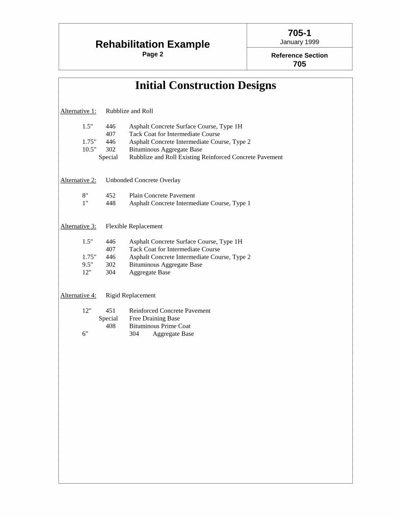
Rehabilitation ExamplePage 2
705-1January 1999
Reference Section705
Initial Construction Designs
Alternative 1: Rubblize and Roll
1.5" 446 Asphalt Concrete Surface Course, Type 1H407 Tack Coat for Intermediate Course
1.75" 446 Asphalt Concrete Intermediate Course, Type 210.5" 302 Bituminous Aggregate Base Special Rubblize and Roll Existing Reinforced Concrete Pavement
Alternative 2: Unbonded Concrete Overlay
8" 452 Plain Concrete Pavement1" 448 Asphalt Concrete Intermediate Course, Type 1
Alternative 3: Flexible Replacement
1.5" 446 Asphalt Concrete Surface Course, Type 1H407 Tack Coat for Intermediate Course
1.75" 446 Asphalt Concrete Intermediate Course, Type 29.5" 302 Bituminous Aggregate Base12" 304 Aggregate Base
Alternative 4: Rigid Replacement
12" 451 Reinforced Concrete Pavement Special Free Draining Base
408 Bituminous Prime Coat6" 304 Aggregate Base

Rehabilitation ExamplePage 3
705-1January 1999
Reference Section705
Widening Buildups
Alternative 1: Rubblize and Roll
1.5" 446 Asphalt Concrete Surface Course, Type 1H407 Tack Coat for Intermediate Course
1.75" 446 Asphalt Concrete Intermediate Course, Type 210.5" 302 Bituminous Aggregate Base12" 304 Aggregate Base
Alternative 2: Unbonded Concrete Overlay
12" 452 Plain Concrete Pavement13" 304 Aggregate Base

Rehabilitation ExamplePage 4
705-1January 1999
Reference Section705
Anticipated Future Maintenance
Alternative 1: Rubblize and Roll
@ 12 years: 1.5" mill and fill@ 20 years: 4" overlay with milling@ 30 years: 1.5" mill and fill
Alternative 2: Unbonded Concrete Overlay
@ 25 years Repair 5% of the pavement, grind for smoothness and reseal joints
Alternative 3: Flexible Replacement
@ 15 years: 2" mill and fill@ 25 years: 4" overlay with milling
Alternative 4: Rigid Replacement
@ 25 years: Repair 5% of the pavement, grind for smoothness and reseal joints

Rehabilitation ExamplePage 5
705-1January 1999
Reference Section705
Project Summary • Historical Data
Project Numbers 530(57)557(57)
SLM 8.30Project Length 7.84 miles
Pavement Buildup 5.25" Asphalt10" Reinforced Concrete6" Subbase
Joint Spacing 60'Drainage Pipe Underdrains
Rehabilitations to date 571(72)159(86)
• Physical Attributes
Signalized Intersections NoneInterchanges None
Overhead Structures FiveStructure Clearance
0844 16'-3" ) 15'-1"0995 14'-11" ) 15'-3"1111 14'-8" ) 15'-0"1268 14'-0" ) 15'-7"1559 19'-1" ) 14'-10"
At-Grade Structures Three Sets
• Project Evaluation
Overall Condition Fair to PoorPCR/Structural Deduct 59/21
20-year Design ESAL’s 65.5 million (Rigid)47.4 million (Flexible)
ADT (1994) 25390% Trucks (1994) 34%
Functional Classification Rural Interstate

Rehabilitation ExamplePage 6
705-1January 1999
Reference Section705
Initial Construction QuantitiesITEM DESCRIPTION UNIT AMT. Alt. 1 Alt. 2 Alt. 3 Alt. 4
202 Pavement Removed SY 62,400 49,067202 Pavement Removed SY 218,293 218,293202 Wearing Course Rem. SY 220,849 239,738203 Excavation CY 237,668 190,709 215,767 196,060203 Subgrade Compaction SY 324,884 305,996203 Subgrade Compaction SY 545,733 545,733302 Bit. Aggregate Base CY 9.5 144,013 302 Bit. Aggregate Base CY 10.5 90,861302 Bit. Aggregate Base CY 14.5 132,034304 Aggregate Base CY 6 90,956304 Aggregate Base CY 12 112,193304 Aggregate Base CY 12 181,911304 Aggregate Base CY 13 112,510 407 Tack Coat Gal 40,930 40,930 408 Bituminous Prime Coat Gal 218,293446 AC Surface, Type 1 CY 1.5 22,739 22,739 446 AC Intermediate, Type 2 CY 1.75 26,529 26,529 448 AC Intermediate, Type 1 CY 1 15,159452 Plain Concrete Pavem't SY 8 239,738452 Plain Concrete Pavem't SY 12 305,996 545,733
Special Rubblize and Roll SY 155,893Special Free Draining Base SY 545,733

Rehabilitation ExamplePage 7
705-1January 1999
Reference Section705
Future Maintenance QuantitiesITEM DESCRIPTION UNIT AMT. Alt. 1 Alt. 2 Alt. 3 Alt. 4
@ 12 Years254 Pavement Planing SY 545,733254 Patching Planed Surface SY 3% 16,372407 Tack Coat Gal 40,930446 AC Surface, Type 1 CY 1.5 22,739
@ 15 Years254 Pavement Planing SY 545,733254 Patching Planed Surface SY 3% 16,372407 Tack Coat Gal 40,930446 AC Surface, Type 1 CY 2 30,319
@ 20 Years254 Pavement Planing SY 545,733254 Patching Planed Surface SY 3% 16,372407 Tack Coat Gal 81,860446 AC Surface, Type 1 CY 1.5 22,739446 AC Intermediate, Type 2 CY 2.5 37,898
@ 25 Years254 Pavement Planing SY 545,733254 Patching Planed Surface SY 3% 16,372255 Rigid Repairs SY 5% 16,372 16,327255 Pavement Sawing LF 5% 73,674 73,674407 Tack Coat Gal 81,860446 AC Surface, Type 1 CY 1.5 22,739446 AC Intermediate, Type 2 CY 2.5 37,898801 Longit. Joint Sealing LF 327,440 327,440801 Trans. Joint Sealing LF 313,476 313,476
Special Diamond Grinding SY 327,440 327,440
@ 30 Years254 Pavement Planing SY 545,733254 Patching Planed Surface SY 3% 16,372407 Tack Coat Gal 40,930446 AC Surface, Type 1 CY 1.5 22,739
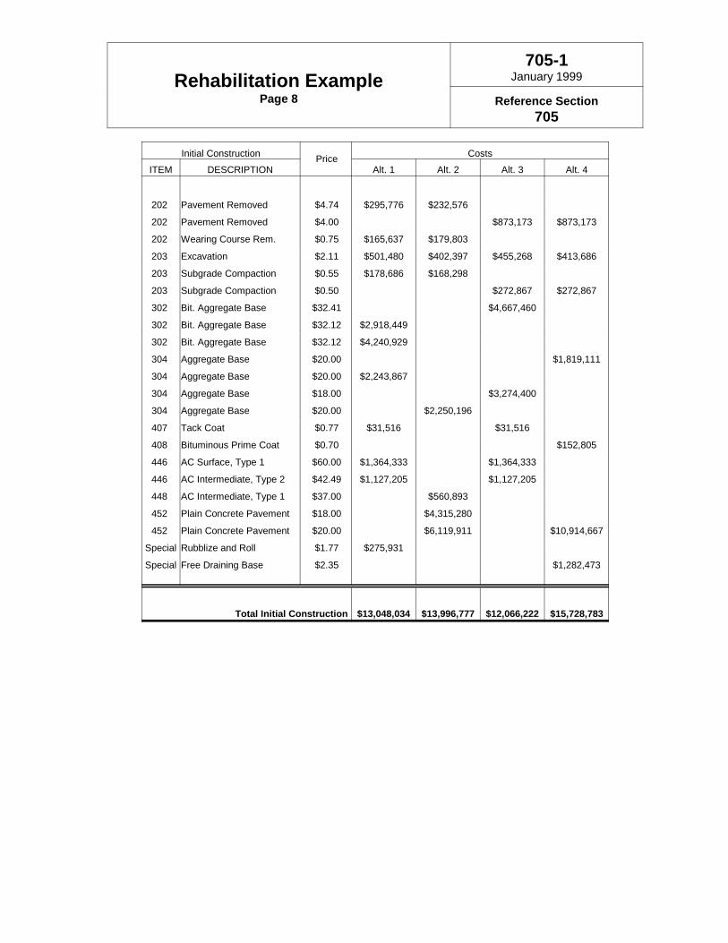
Rehabilitation ExamplePage 8
705-1January 1999
Reference Section705
Initial Construction Price CostsITEM DESCRIPTION Alt. 1 Alt. 2 Alt. 3 Alt. 4
202 Pavement Removed $4.74 $295,776 $232,576
202 Pavement Removed $4.00 $873,173 $873,173
202 Wearing Course Rem. $0.75 $165,637 $179,803
203 Excavation $2.11 $501,480 $402,397 $455,268 $413,686
203 Subgrade Compaction $0.55 $178,686 $168,298
203 Subgrade Compaction $0.50 $272,867 $272,867
302 Bit. Aggregate Base $32.41 $4,667,460
302 Bit. Aggregate Base $32.12 $2,918,449
302 Bit. Aggregate Base $32.12 $4,240,929
304 Aggregate Base $20.00 $1,819,111
304 Aggregate Base $20.00 $2,243,867
304 Aggregate Base $18.00 $3,274,400
304 Aggregate Base $20.00 $2,250,196
407 Tack Coat $0.77 $31,516 $31,516
408 Bituminous Prime Coat $0.70 $152,805
446 AC Surface, Type 1 $60.00 $1,364,333 $1,364,333
446 AC Intermediate, Type 2 $42.49 $1,127,205 $1,127,205
448 AC Intermediate, Type 1 $37.00 $560,893
452 Plain Concrete Pavement $18.00 $4,315,280
452 Plain Concrete Pavement $20.00 $6,119,911 $10,914,667
Special Rubblize and Roll $1.77 $275,931
Special Free Draining Base $2.35 $1,282,473
Total Initial Construction $13,048,034 $13,996,777 $12,066,222 $15,728,783
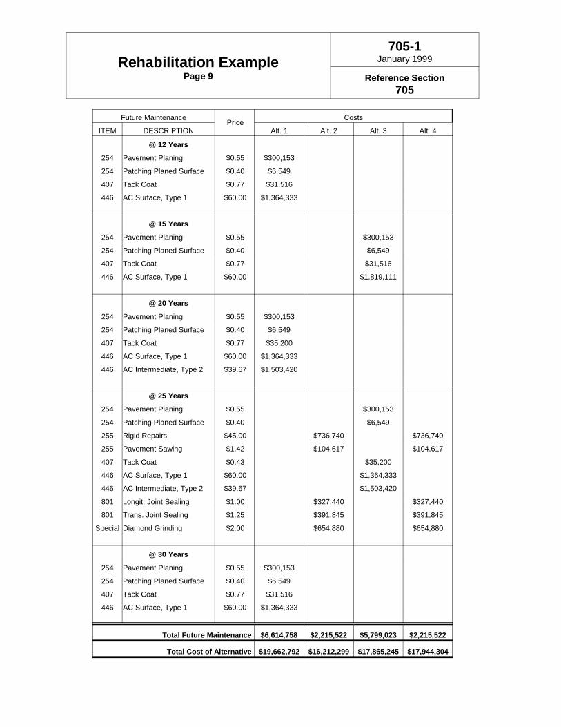
Rehabilitation ExamplePage 9
705-1January 1999
Reference Section705
Future Maintenance Price Costs
ITEM DESCRIPTION Alt. 1 Alt. 2 Alt. 3 Alt. 4
@ 12 Years
254 Pavement Planing $0.55 $300,153
254 Patching Planed Surface $0.40 $6,549
407 Tack Coat $0.77 $31,516
446 AC Surface, Type 1 $60.00 $1,364,333
@ 15 Years
254 Pavement Planing $0.55 $300,153
254 Patching Planed Surface $0.40 $6,549
407 Tack Coat $0.77 $31,516
446 AC Surface, Type 1 $60.00 $1,819,111
@ 20 Years
254 Pavement Planing $0.55 $300,153
254 Patching Planed Surface $0.40 $6,549
407 Tack Coat $0.77 $35,200
446 AC Surface, Type 1 $60.00 $1,364,333
446 AC Intermediate, Type 2 $39.67 $1,503,420
@ 25 Years
254 Pavement Planing $0.55 $300,153
254 Patching Planed Surface $0.40 $6,549
255 Rigid Repairs $45.00 $736,740 $736,740
255 Pavement Sawing $1.42 $104,617 $104,617
407 Tack Coat $0.43 $35,200
446 AC Surface, Type 1 $60.00 $1,364,333
446 AC Intermediate, Type 2 $39.67 $1,503,420
801 Longit. Joint Sealing $1.00 $327,440 $327,440
801 Trans. Joint Sealing $1.25 $391,845 $391,845
Special Diamond Grinding $2.00 $654,880 $654,880
@ 30 Years
254 Pavement Planing $0.55 $300,153
254 Patching Planed Surface $0.40 $6,549
407 Tack Coat $0.77 $31,516
446 AC Surface, Type 1 $60.00 $1,364,333
Total Future Maintenance $6,614,758 $2,215,522 $5,799,023 $2,215,522
Total Cost of Alternative $19,662,792 $16,212,299 $17,865,245 $17,944,304

13
14
15
16
17
18
19
20
Tota
l Cos
tM
illion
s
0% 1% 2% 3% 4% 5% 6%Discount Rate
Alt. 1 Alt. 2 Alt. 3 Alt. 4
Rehabilitation ExamplePage 10
705-1January 1999
Reference Section705
Sensitivity Analysis of the Discount Rate
The Discount Rate is a tool used in evaluating the time value of money. It is broadlydefined as the difference between market interest rates and inflation. Because costsare incurred at different points in time over the life of a pavement, the discount rate isused to compare these costs in terms of constant dollars. In this case, 1998 dollarshave been used as constant dollars. A survey of states done in the mid 1990'sindicated the range of discount rates used throughout the country varies from 0% to7%. The most common rate used was 4%. Rather than using just one discount rate,a range of rates has been used to show how different rates affect the apparent leastcost alternative.
Rate Alt. 1 Alt. 2 Alt. 3 Alt. 4
0% $19,662,792 $16,212,299 $17,868,929 $17,944,304
1% $18,452,579 $15,724,371 $16,802,534 $17,456,376
2% $17,490,419 $15,347,206 $15,949,282 $17,079,211
3% $16,720,706 $15,054,922 $15,263,552 $16,786,928
4% $16,101,215 $14,827,856 $14,710,047 $16,559,862
5% $15,599,695 $14,651,027 $14,261,344 $16,383,0326% $15,191,367 $14,515,990 $13,896,057 $16,244,996

Rehabilitation ExamplePage 11
705-1January 1999
Reference Section705
Lane Closure Summary*
Action Alt. 1 Alt. 2 Alt. 3 Alt. 4Initial Construction 614 381 562 577Future Maintenance
@ 12 Years 31@ 15 Years 31@ 20 Years 143@ 25 Years 119 143 119@ 30 Years 31
Total of Future 205 119 174 119
Total No. of Days 819 500 736 696
* Lane Closure Summary is for comparison purposes only and isnot an estimate of the actual time for construction as many factorsexist which were not considered.

New Pavement ExamplePage 1
705-2June 1999
Reference Section705
New Pavement Type Approval
Project: XYZ-999-2.66 Date: February 29, 1999 Length: 4.48 miles PID No.: 98765 Plans: 10% complete Program Amount: $15,000,000
! Flexible Alternative:
1.5" 446 Asphalt Concrete Surface Course, Type 1H1.75" 446 Asphalt Concrete Intermediate Course, Type 27.5" 302 Bituminous Aggregate Base
307 Non-Stabilized Drainage Base Type IA or NJ408 Bituminous Prime Coat
6" 304 Aggregate Base
Anticipated Future Maintenance@ 12 Years: Mill and fill mainline only with 1.5 inches@ 22 Years: Repair 1% of the pavement, mill and overlay with 4 inches
! Rigid Alternative:
10" 452 Plain Concrete Pavement307 Non-Stabilized Drainage Base Type IA408 Bituminous Prime Coat
6" 304 Aggregate Base
Anticipated Future Maintenance@ 22 Years: Repair 2% full depth and 1% partial depth and grind for smoothness
PLEASE INDICATE BELOW YOUR APPROVAL OF ONE OF THE ALTERNATIVES THEN RETURNTO MATERIALS MANAGEMENT
Pavement Selection Committee New Design Approval Flexible Rigid
District Deputy Director ________________________________________
Assistant Director for Transportation Policy ________________________________________
Assistant Director for Field Operations ________________________________________
Deputy Director of Engineering Policy ________________________________________

New Pavement ExamplePage 2
705-1June 1999
Reference Section705
Selection Summary Sheet
The Flexible Alternative has been selected by the District. The following discussion concerning this selection isprovided in an effort to communicate the rational for this decision.
Principal Factors
LCCA: The Flexible Alternative has the lowest life-cycle cost at all discount rates although the Rigid Alternativeis within 5% of it at zero percent discount rate.
Initial Cost: The Flexible Alternative has the lowest initial cost and the Rigid Alternative is more than 10%greater.
User Delay: The Flexible Alternative has almost twice as many days of lane closure as the Rigid Alternative. Thisproject is located in a rural area with low ADT however, and we don’t feel the lane closures will causeany backups or significant disruption to the traveling public and the other factors in favor of the FlexibleAlternative outweigh this drawback.
Municipal Preference: This project is rural and not located within any municipality.
Secondary Factors
Geometrics: This project is located on flat terrain with very little grade. There are no geometric constraints whichwould favor either alternative.
Constructability: This project is new pavement on new alignment and any pavement can be constructed easily.
Availability of Local Materials: There are currently no available aggregate sources nearby for coarse aggregateswhich have passed the D-cracking test required for concrete.
Other Issues: Our District has had very good performance with flexible pavement the past.

New Pavement ExamplePage 3
705-2June 1999
Reference Section705
Project Summary
20-year Design ESAL’s 24.7 million (Rigid)16.7 million (Flexible)
ADT (1997) 8430% Trucks (1997) 12 %
Functional Classification Rural Principle Arterial
Days of Lane Closure*
Action Flexible Rigid
Initial Construction (Not applicable, new location)
Future Maintenance
@ 12 Years 7@ 22 Years 53 34
Total of Future Maint. 60 34
Total No. of Days 60 34
* Lane Closure summary is for comparison purposes only and is not an estimate of the actual timefor construction as many factors exist which were not considered.

New Pavement ExamplePage 4
705-2June 1999
Reference Section705
Initial Construction Quantities CostsItem Description Unit Amt. Flexible Rigid Price Flexible Rigid
203 Subgrade Compaction SY 199,748 199,748 $0.58 $115,854 $115,854302 Bituminous Aggregate Base CY 7.5 42,709 $44.00 $1,879,211304 Aggregate Base CY 6 35,044 34,167 $21.10 $739,419 $720,934307 Non-Stabilized DB SY 199,748 199,748 $3.17 $633,202 $633,202407 Tack Coat for Intermediate Gal 14,981 $0.65 $9,738408 Prime Coat Gal 79,899 79,899 $0.84 $67,115 $67,115446 AC Surface, Type 1H CY 1.5 8,323 $68.15 $567,202446 AC Intermediate, Type 2 CY 1.75 9,710 $43.47 $422,093452 Plain Concrete SY 10 199,748 $21.00 $4,194,714
Total Cost of Initial Construction $4,433,834 $5,731,819
Future Maintenance Quantities CostsItem Description Unit Amt. Flexible Rigid Price Flexible Rigid
@ 12 Years254 Pavement Planing SY 126,157 $0.59 $74,433254 Patching Planed Surface SY 1,262 $2.95 $3,722407 Tack Coat Gal 9,462 $0.71 $6,718446 AC Surface, Type 1H CY 1.5 5,257 $68.15 $358,233
@ 22 Years253 Pavement Repair SY 0.5% 631 $85.97 $54,229254 Pavement Planing SY 199,748 $0.59 $117,851254 Patching Planed Surface SY 1,997 $2.95 $5,893407 Tack Coat Gal 14,981 $0.65 $9,738407 Tack Coat for Intermediate Gal 14,981 $0.65 $9,738446 AC Surface, Type 1H CY 1.5 8,323 $68.15 $567,202446 AC Intermediate, Type 2 CY 2.5 13,871 $43.47 $602,990
@ 22 Years255 Rigid Repairs SY 2% 2,523 $56.28 $142,002255 Pavement Sawing LF 11,354 $2.17 $24,638256 Bonded Patching SF 1% 11,354 $30.00 $340,623
Spec. Diamond Grinding SY 126,157 $2.44 $307,823
Total Cost of Future Maintenance $1,810,745 $815,086
Total Cost of Alternative $6,244,578 $6,546,905
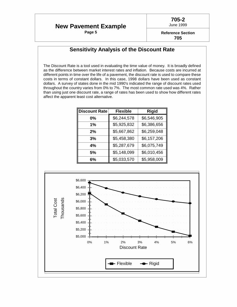
$5,000
$5,200
$5,400
$5,600
$5,800
$6,000
$6,200
$6,400
$6,600
Tota
l Cos
tTh
ousa
nds
0% 1% 2% 3% 4% 5% 6%Discount Rate
Flexible Rigid
New Pavement ExamplePage 5
705-2June 1999
Reference Section705
Sensitivity Analysis of the Discount Rate
The Discount Rate is a tool used in evaluating the time value of money. It is broadly definedas the difference between market interest rates and inflation. Because costs are incurred atdifferent points in time over the life of a pavement, the discount rate is used to compare thesecosts in terms of constant dollars. In this case, 1998 dollars have been used as constantdollars. A survey of states done in the mid 1990's indicated the range of discount rates usedthroughout the country varies from 0% to 7%. The most common rate used was 4%. Ratherthan using just one discount rate, a range of rates has been used to show how different ratesaffect the apparent least cost alternative.
Discount Rate Flexible Rigid0% $6,244,578 $6,546,9051% $5,925,832 $6,386,6562% $5,667,862 $6,259,0483% $5,458,380 $6,157,2064% $5,287,679 $6,075,7495% $5,148,099 $6,010,4566% $5,033,570 $5,958,009

Appendix A
Pavement Design and Selection Process


Approved: Effective: June 10, 1999Responsible Office: Materials ManagementPolicy Number: 515-002 (P)
//s// Gordon Proctor Page 1 of 11Gordon ProctorDirector
PAVEMENT DESIGN AND SELECTION PROCESS
POLICY STATEMENT:
The Ohio Department of Transportation (ODOT) must select projects and design newpavements and rehabilitations of existing pavements such that they: are structurally adequateto serve the anticipated loadings, employ cost-effective materials, require a minimum amountof maintenance, and result in long-term customer satisfaction. This goal is brought about byassuring a consistent, statewide strategy exists for identifying how resources will be utilized,that proper pavement treatments are applied at the proper time, cost-effective materials areused and best practice construction methodologies are pursued.
This Policy will establish uniform procedures to assure that the above objectives are achievedand the experience, collective knowledge, and technical expertise of all involved in thepavement design and selection process are considered.
AUTHORITY:
The Director of Transportation’s authority to establish rules as conferred by 5501.02 of theOhio Revised Code.
REFERENCES:
# “Pavement Design & Rehabilitation Manual”, Ohio Department of Transportation,current revision.
# “Guide for Design of Pavement Structures”, American Association of State Highwayand Transportation Officials, 1993.
# “Pavement Rehabilitation Design Training Course - Participants Manual” Y.J.Chou,A.A. Morse, D.W. Miller, 1997.
# “Specifications for Subsurface Investigations”, Ohio Department of Transportation,November 1, 1995.

Policy No. 515-002 (P)Page 2 of 11
# “Implementation and Revision of Developed Concepts for ODOT PavementManagement Program--Volume II Pavement Condition Rating Manual”, February1987.
SCOPE:
This policy applies to all multi-lane and all National Highway System (NHS) pavementsunder the jurisdiction of the Ohio Department of Transportation. Routes other than multi-lane and NHS are to be managed and designed consistent with fiscal responsibility and soundpavement management practices.
Each District Deputy Director will administer this policy, with the approval of the PavementSelection Committee (PSC) and the Federal Highway Administration (FHWA) whenrequired. The Pavements Section of the Office of Materials Management (PavementsSection) will provide technical assistance, advice, training, and support.
DEFINITIONS:
Analysis Period - The number of years for which a Life-Cycle Cost Analysis is made.
Design Period - The number of years, over which a pavement structure is expected todeteriorate from its initial condition (new or rehabilitated) to its terminal serviceability. Thelength of this period is directly related to the loading the pavement is expected to carry.
Functional Characteristics - Qualities of a pavement such as surface smoothness, skidresistance, and non-load related distresses such as block cracking, and oxidation of asphaltpavement surfaces.
Major Rehabilitation - Work performed on a pavement intended to restore structural integrityand functional characteristics.
Minor Rehabilitation - Work performed on a pavement intended to restore functionalcharacteristics and protect the structural integrity.
Multi-Lane Pavements - Pavements with four or more lanes. Continuous two-way left turnlanes are considered lanes in this definition.
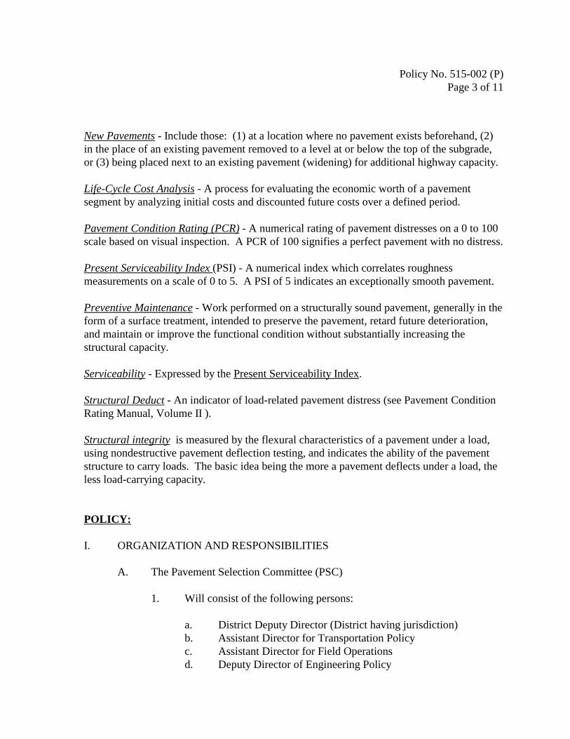
Policy No. 515-002 (P)Page 3 of 11
New Pavements - Include those: (1) at a location where no pavement exists beforehand, (2)in the place of an existing pavement removed to a level at or below the top of the subgrade,or (3) being placed next to an existing pavement (widening) for additional highway capacity.
Life-Cycle Cost Analysis - A process for evaluating the economic worth of a pavementsegment by analyzing initial costs and discounted future costs over a defined period.
Pavement Condition Rating (PCR) - A numerical rating of pavement distresses on a 0 to 100scale based on visual inspection. A PCR of 100 signifies a perfect pavement with no distress.
Present Serviceability Index (PSI) - A numerical index which correlates roughnessmeasurements on a scale of 0 to 5. A PSI of 5 indicates an exceptionally smooth pavement.
Preventive Maintenance - Work performed on a structurally sound pavement, generally in theform of a surface treatment, intended to preserve the pavement, retard future deterioration,and maintain or improve the functional condition without substantially increasing thestructural capacity.
Serviceability - Expressed by the Present Serviceability Index.
Structural Deduct - An indicator of load-related pavement distress (see Pavement ConditionRating Manual, Volume II ).
Structural integrity is measured by the flexural characteristics of a pavement under a load,using nondestructive pavement deflection testing, and indicates the ability of the pavementstructure to carry loads. The basic idea being the more a pavement deflects under a load, theless load-carrying capacity.
POLICY:
I. ORGANIZATION AND RESPONSIBILITIES
A. The Pavement Selection Committee (PSC)
1. Will consist of the following persons:
a. District Deputy Director (District having jurisdiction)b. Assistant Director for Transportation Policyc. Assistant Director for Field Operationsd. Deputy Director of Engineering Policy

Policy No. 515-002 (P)Page 4 of 11
2. The Assistant Director for Transportation Policy will chair the PSC.
3. The PSC:
a. Will meet to make decisions based on consensus.
b. May call on the District Pavement Designer and/or the CentralOffice Pavement Section representative to assist the PSC orparticipate in the meeting.
4. Pavement type selections for new pavements and major rehabilitationprojects that exceed four lane-miles (six lane-kilometers) in length,must be approved by the Committee.
B. Office of Materials Management - Pavements Section will be responsible for:
1. All policies, manuals, and guidelines concerning pavement design,maintenance, and rehabilitation.
2. Providing advice and assistance to the PSC.
3. Review District Pavement Review Team recommendation and provideconcurrence/nonconcurrence documentation to the PSC.
4. Providing technical support, advice, training, and assistance to Districtpersonnel involved in development of Work Plans, project scopes,design, and preparation of plans.
C. District Offices
1. The Districts will be responsible for all project-related design activitiesincluding pavement design, pavement rehabilitation design, and life-cycle cost analysis.
2. The District will be responsible for the development of acomprehensive pavement management strategy as defined in SectionIV.F.1.
3. The District will establish a Pavement Review Team which will, at aminimum, consist of:

Policy No. 515-002 (P)Page 5 of 11
a. District pavement designer
b. Appropriate District Planning, Production and HighwayManagement personnel.
c. County Manager
d. A representative from FHWA.
4. The Pavement Review Team will:
a. Review all candidate projects in the preventive maintenance,minor rehabilitation and major rehabilitation categories toensure the proper treatments are being applied to the right roadsat the right time.
b. Develop a life-cycle cost analysis on all new construction andmajor rehabilitation projects in accordance with Section II andprovide a summary report in accordance with the PavementDesign and Rehabilitation Manual.
c. Transmit the report and life-cycle cost analysis (wherenecessary) to the PSC under the signature of the DistrictDeputy Director and through the Office of MaterialsManagement - Pavements Section.
5. Districts will be responsible for maintaining pavement design recordsand documentation concerning project decisions for a time periodwhich exceeds the life of the strategy.
II. GENERAL
A. The results of life-cycle cost analyses will be given thorough consideration inthe determination of pavement type for new pavements and majorrehabilitations. In addition to the LCCA, the principal and secondary factorsto be considered are listed in the table below.
Principal Factors Secondary FactorsInitial Cost GeometricsUser Delay ConstructabilityMunicipal Preference Availability of Local Materials

Policy No. 515-002 (P)Page 6 of 11
B. Life-cycle cost analyses will use an Analysis Period of 35 years, and will beperformed in accordance with the Pavement Design and RehabilitationManual. All construction costs anticipated to accrue during the period will beconsidered in the analyses.
III. PROCEDURES FOR NEW PAVEMENTS
A. Structural Design Parameters
1. Pavement design will be done following the Pavement Design andRehabilitation Manual, Sections 200, 300, and 400.
2. New pavements will be designed structurally for a twenty year periodusing projected equivalent single-axle loadings and appropriate soilsupport values.
B. Pavement Type Selection
1. Procedures to follow for pavement selection vary with the length of thepavement to be constructed. For projects with more than four lane-miles (six-lane kilometers) of mainline pavement, approval ofpavement type selection must be obtained from the PSC. Projects thatcontain less than four lane-miles (six-lane kilometers) need onlyconsensus from the District Pavement Review Team and approval ofthe District Deputy Director.
2. Projects that require PSC approval also require a Life-Cycle CostAnalysis following current ODOT practice as outlined in Section 700of the Pavement Design & Rehabilitation Manual. The analysis willinclude both rigid and flexible alternatives. A completed analysis,indicating the District’s preferred alternative, is to be sent to thePavements Section under the District Deputy Director’s signature. ThePavements Section will review the analysis and provideconcurrence/nonconcurrence documentation to the PSC.
IV. PROCEDURES FOR EXISTING PAVEMENTS
A. Network-Level Corrective Action Categories

Policy No. 515-002 (P)Page 7 of 11
The Pavement Management System (PMS), managed by the Office ofTechnical Services, provides a detailed ranking and distress identification forall pavements on a District and Statewide basis. An initial determination forNetwork-Level Corrective Action Category will be made according to thefollowing table. This table relates corrective actions with the PavementCondition Rating values predicted to exist at the time any corrective actionsare expected to take place. Pavement condition prediction will be based onthe latest analysis from ODOT’s PMS as detailed in Section 100 of thePavement Design & Rehabilitation Manual. Any deviations to these categoriesmust be justified and documented in the project- level analysis.
Predicted PCR value Network-Level Corrective Action Category *PCR> 85 No action required85>PCR>75 Preventive maintenance75>PCR>55 Minor rehabilitationPCR<55 Major rehabilitation
* Pavements having a structural deduct greater than or equal to 25 generallyrequire major rehabilitation, no matter of the overall PCR.
B. Project-Level Corrective Action Considerations
1. Although the Network-Level Corrective Action Categories provideinitial strategies as a function of predicted PCR value, it must beunderstood that these strategies are for initial estimates only and therewill be situations where this framework will not apply. Therefore, it isimperative that each project has a detailed project-level analysisperformed before making final detailed design decisions concerningthe pavement.
2. The project-level analysis should always begin with a PCR history plotcoupled with all available design, construction, and maintenanceinformation regarding the project. A field review to consider all thenecessary information for the project-level analysis should beperformed by the District Pavement Review Team. The Central OfficePavement Section is available to provide assistance on a case by casebasis.
C. Preventive Maintenance - General

Policy No. 515-002 (P)Page 8 of 11
1. Preventive Maintenance strategies and techniques are identified in thePavement Preventive Maintenance Program Guidelines.
2. Preventive Maintenance projects funded under this program (which bydefinition have only the intention of correcting functional distress,restoring ride quality and extending the service life of the existingpavement structure) will not require design exceptions.
3. Candidate projects will be field reviewed by the Pavement ReviewTeam, after the required project data and analysis has been assembled. The Pavement Review Team will make recommendations regardingappropriate treatments.
D. Minor Rehabilitations - General
1. Candidate projects will be field reviewed by the Pavement ReviewTeam, after the required project data and analysis has been assembled. The Pavement Review Team will make recommendations regardingappropriate treatments
2. Design parameters will be determined from the Pavement Design &Rehabilitation Manual.
3. Rehabilitations will be designed structurally for a 12-year period usingprojected equivalent single-axle loading and dynaflect data. Whereanalysis shows no structural overlay is required, the project can beconsidered as preventive maintenance.
4. Upgrading of all roadside appurtenances and appropriate bridgerehabilitations or replacements need to be considered in conjunctionwith minor rehabilitation projects.
5. Minor rehabilitation strategies will be chosen by the District.
E. Major Rehabilitations - General
1. Candidate projects will be field reviewed by the Pavement ReviewTeam, after the required project data and analysis has been assembled. The Pavement Review Team will make recommendations regardingappropriate treatments

Policy No. 515-002 (P)Page 9 of 11
2. Design parameters will be determined using Sections 300, 400, and600 of the Pavement Design & Rehabilitation Manual
3. Strategies will be designed structurally for a 20-year design periodusing projected equivalent single-axle loading and dynaflect data.
4. Upgrading of all roadside appurtenances and appropriate bridgerehabilitations or replacements should be done in conjunction withmajor rehabilitation projects.
5. The following alternative rehabilitation strategies will be consideredfor major rehabilitations. A Life-Cycle Cost Analysis will be used forcomparison purposes. Acceptable strategies include:
a. Complete Replacement - Rigid Pavement (required)
b. Complete Replacement - Flexible Pavement (required)
c. Complete Replacement - Composite Pavement (optional)
d. Fractured Slab Techniques:(1) Rubblize & Roll - all concrete pavements and bases(2) Crack & Seat - Plain concrete pavement and base
e. Unbonded Concrete Overlay / Whitetopping
6. Strategy Selection will be handled the same as defined for NewPavements, Section III.
F. Project Development
1. Each District will be responsible for a ten-year preventive maintenanceprogram and a ten-year minor and major rehabilitation program to beestablished and updated each year as a part of the District’s Work Plan. The ten-year minor and major rehabilitation program shall bedetermined during the biennial development of the four-year STIP/TIP.These programs shall be sent to the Pavements Section forinformational purposes upon the completion of the District’s WorkPlan. Additionally, the Pavements Section shall be notified of anyrevisions to these programs throughout the completion of the District’sWork Plan. The District’s updated program shall indicate the need for

Policy No. 515-002 (P)Page 10 of 11
Dynaflect data. Dynaflect data should not be obtained more than fouryears prior to construction.
2. A reevaluation of the pavement design will be necessary if the projectaward date surpasses the originally projected date (at the time ofpavement analysis) by two years.
G. Quality Assurance Reviews
1. The Office of Multi-modal Planning will be the lead office inestablishing statewide and district trends in pavement condition.
2. The Office of Materials Management will:
a. Do quality assurance reviews at the time of construction todetermine:
(1) Appropriateness of strategy selection(2) Appropriateness of the pavement treatment and design
procedure(3) Adherence to this policy
b. Share best practices identified by the quality assurance reviewswith the districts.
c. Identify training needs.
H. Training:
The following courses must be included in appropriate personnel’s trainingschedule over a three-year period:
1. Planning and Production Staff:
a. Pavement Condition Rating
b. Pavement Design Essentials
c. Pavement Rehabilitation
d. Pavement Type Selection

Policy No. 515-002 (P)Page 11 of 11
2. Highway Management Staff will provide training in appropriateconstruction techniques (i.e., winter construction schools)
I. Fiscal Analysis:
1. The objective of this policy is to implement a strategy that optimizesthe combination of pavement preventive maintenance, routinemaintenance, rehabilitation, and reconstruction techniques to providethe lowest life-cycle costs consistent with a high level of service to theroad users.
2. The strategy depends on implementing a system of preventivemaintenance that keeps good roads in good condition. Variousnational studies have confirmed the effectiveness of a soundpreventive maintenance program in reducing the life-cycle costs ofpavements while providing a high level of service.
3. Overall, in the short term, this policy is intended to be cost-neutral,neither increasing nor decreasing the level of investment in pavementmaintenance and restoration. Initially, investing in preventivemaintenance represents a shift in investment funds relative to the priorstrategy of only minor and major rehabilitation. Some initial costreduction will be realized by reducing the minor rehabilitation designperiod from 20 to 12 years which will balance out over a period oftime. Long term benefits in the form of improved levels ofserviceability and decreases in the costs of maintaining, rehabilitating,and reconstructing pavements can be expected.


Appendix B
Pavement Guidelines for Treatment of High Stress Locations

January 1999
PAVEMENT GUIDELINES FOR TREATMENT OFHIGH STRESS LOCATIONS
BACKGROUND:
These guidelines are intended to be used to reduce or eliminate rutting and or shoving problemsassociated with the use of asphalt concrete pavement surfaces.
These guidelines are intended to be used by District office staff in making best practice decisionsregarding pavement resurfacing and design considerations.
As there are no previous documents regarding the treatment of rutting and or shoving, it isanticipated there will be numerous questions dealing with special circumstance issues. Technicalassistance with these guidelines is available by contacting any of the following individuals:
Dave Powers - Asphalt Materials Engineer, Office of Materials Management (614-275-1387)Bill Christensen - Flexible Pavement Engineer, Office of Highway Management (614-644-6634)Aric Morse - Pavement Design Engineer, Office of Materials Management (614-275-1316)
DEFINITIONS:
Rutting: Rutting is visually identified by vertical depressions in the pavement surface along thewheel tracks. Rutting is measured transversely across the depression using a string line or otherappropriate straight edge. Rutting is generally considered significant when it approaches 0.4inches (~10 mm) in depth. The presence of significant rutting may or may not indicate a highstress location. Circumstances resulting in faulty mix design, production or placement couldcontribute to rutting.
Shoving: Shoving is a longitudinal displacement of a localized area of the pavement surface. Itis generally caused by braking or accelerating vehicles, and is usually located on hills, curves,or intersections. Shoving may also include vertical displacement. Shoving is generallyconsidered significant when it affects ride quality. The presence of shoving may or may notindicate a high stress location. Circumstances resulting in faulty mix design, production orplacement could contribute to shoving.
Medium Traffic: Medium traffic is 50 to 1499 trucks per day using the current year designation.
High Traffic: High traffic is 1500 or more trucks per day using the current year designation.
High Stress Location: High stress locations are found at areas of high acceleration and braking,at intersections, sharp curves, ramps, and where heavy vehicles frequent at slow speeds. Highstress locations occur at intersections with forced stop control and one or more of the followingcriteria:
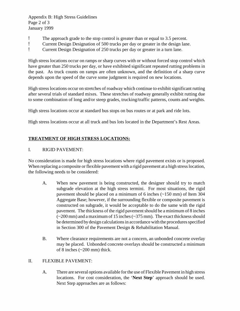
Appendix B: High Stress GuidelinesPage 2 of 3January 1999
! The approach grade to the stop control is greater than or equal to 3.5 percent.! Current Design Designation of 500 trucks per day or greater in the design lane.! Current Design Designation of 250 trucks per day or greater in a turn lane.
High stress locations occur on ramps or sharp curves with or without forced stop control whichhave greater than 250 trucks per day, or have exhibited significant repeated rutting problems inthe past. As truck counts on ramps are often unknown, and the definition of a sharp curvedepends upon the speed of the curve some judgment is required on new locations.
High stress locations occur on stretches of roadway which continue to exhibit significant ruttingafter several trials of standard mixes. These stretches of roadway generally exhibit rutting dueto some combination of long and/or steep grades, trucking/traffic patterns, counts and weights.
High stress locations occur at standard bus stops on bus routes or at park and ride lots.
High stress locations occur at all truck and bus lots located in the Department’s Rest Areas.
TREATMENT OF HIGH STRESS LOCATIONS:
I. RIGID PAVEMENT:
No consideration is made for high stress locations where rigid pavement exists or is proposed.When replacing a composite or flexible pavement with a rigid pavement at a high stress location,the following needs to be considered:
A. When new pavement is being constructed, the designer should try to matchsubgrade elevation at the high stress termini. For most situations, the rigidpavement should be placed on a minimum of 6 inches (~150 mm) of Item 304Aggregate Base; however, if the surrounding flexible or composite pavement isconstructed on subgrade, it would be acceptable to do the same with the rigidpavement. The thickness of the rigid pavement should be a minimum of 8 inches(~200 mm) and a maximum of 15 inches (~375 mm). The exact thickness shouldbe determined by design calculations in accordance with the procedures specifiedin Section 300 of the Pavement Design & Rehabilitation Manual.
B. Where clearance requirements are not a concern, an unbonded concrete overlaymay be placed. Unbonded concrete overlays should be constructed a minimumof 8 inches (~200 mm) thick.
II. FLEXIBLE PAVEMENT:
A. There are several options available for the use of Flexible Pavement in high stresslocations. For cost consideration, the ‘Next Step’ approach should be used.Next Step approaches are as follows:

Appendix B: High Stress GuidelinesPage 3 of 3January 1999
1. In a high stress area which would otherwise require a medium trafficpavement mix design, specify a heavy traffic pavement mix design. Allhigh stress areas using a Type 1H design shall use Item 446 regardless ofthe quantity limitations given in Section 404.1.
2. In a high stress area which would otherwise require a heavy trafficpavement mix design, specify a non-standard modified asphalt concretepavement mix design. A list of all available modified asphalt concretemixes is on file with the Office of Materials Management. Contact theAsphalt Materials Section for a current list of available options.
B. For all high stress locations where rutting is evident, pavement planing should bespecified to remove all deformed material.
1. For flexible pavement, planing should be specified to the bottom of thematerial responsible for the rutting. In order to determine the responsiblelayer, the comparison of pavement cores taken in the rutted area withcores taken outside of the rut may be helpful. Where this information isnot available, best practice is to remove up to 3 inches (~75 mm) belowthe deepest portion of the rut. Standard practice concerning tack coatshould be followed prior to the placement of the Next Step asphalt mixes.
2. For composite pavement, planing should be specified as per II.B.1.Where the surface of the rigid base pavement is within 2 inches (~50mm)of the required milled depth, best practice is to take the milling down tothe concrete, in order to provide a course of larger aggregate (301 or 302)material.
C. Lift combinations and thickness requirements will generally be the same aswould be required for a standard flexible pavement or overlay.
LIMITS OF HIGH STRESS LOCATIONS:
The limits of the high stress treatment should be determined as follows:
A. A minimum of 250 feet (~75 m) back from the location of stop termini or trafficsignal.
B. The length of the turn lane.
C. The limits of the existing problem condition.
In urban areas where several intersections exist within close proximity to each other and meethigh stress criteria, best practice is to specify the required high stress mix the length of thesection bounded at the outermost limits of the high stress locations.

Appendix C
Simplified Pavement Design for Short Projects

Simplified Pavement Designs for Short Projects
Many projects exist such as bridge replacement projects which include a short stretch of new pavementor pavement replacement. For projects in which the total length of new pavement or pavementreplacement is less than 300 feet (~100 m), the chart on the following page may be used in lieu of acomplete pavement design per Sections 200, 300 and 400 of this Manual. The buildups given on thechart are conservative and are based on the amount of truck traffic expected for the opening day. Thefollowing procedures and precautions should be recognized:
1. The length of pavement replacement is exclusive of bridge length, where applicable.
2. The designer should first evaluate the buildup of the existing pavement. If the strength of theexisting pavement exceeds the chart value, then the existing design should be perpetuated.
3. Where opening day truck traffic exceeds 800, this chart is not to be used and the proceduresdescribed in Sections 200, 300 and 400 of this Manual are to be followed.
4. If it is known in advance that poor soils may be encountered at subgrade level or if the designeris unsure of proper subgrade or slope treatments, review by the Geotechnical Design Section ofthe Office of Materials Management is recommended.
5. The designer is always welcome to do a complete design per Sections 200, 300 and 400 ratherthan using the chart.
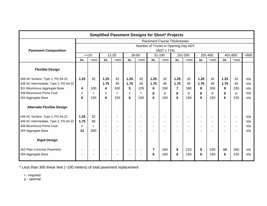
Simplified Pavement Designs for Short* ProjectsPavement Course Thicknesses
Number of Trucks in Opening Day ADTPavement Composition (ADT x T24)
<=10 11-25 26-50 51-100 101-200 201-400 401-800 >800in. ~mm in. ~mm in. ~mm in. ~mm in. ~mm in. ~mm in. ~mm
Flexible Design
448 AC Surface, Type 1, PG 64-22 1.25 32 1.25 32 1.25 32 1.25 32 1.25 32 1.25 32 1.25 32 n/a 448 AC Intermediate, Type 2, PG 64-22 1.75 45 1.75 45 1.75 45 1.75 45 1.75 45 1.75 45 n/a 301 Bituminous Aggregate Base 4 100 4 100 5 125 6 150 7 180 8 200 9 230 n/a 408 Bituminous Prime Coat r r r r r r p p p p p p p p n/a 304 Aggregate Base 6 150 6 150 6 150 6 150 6 150 6 150 6 150 n/a
Alternate Flexible Design
448 AC Surface, Type 1, PG 64-22 1.25 32 - - - - - - - - - - - - n/a 448 AC Intermediate, Type 2, PG 64-22 1.75 45 - - - - - - - - - - - - n/a 408 Bituminous Prime Coat r r - - - - - - - - - - - - n/a 304 Aggregate Base 12 300 - - - - - - - - - - - - n/a
Rigid Design
452 Plain Concrete Pavement - - - - - - 7 180 8 210 9 230 10 260 n/a 304 Aggregate Base - - - - - - 6 150 6 150 6 150 6 150 n/a
* Less than 300 linear feet (~100 meters) of total pavement replacement
r - required p - optional

Appendix D
ODOT’s PCR Manual
PAVEMENT CONDITION RATINGSYSTEM
REVIEW OF PCR METHODOLOGY
Report No. FHWA/OH-99/004
Prepared by
Resource International, Inc.
281 Enterprise DriveWesterville, Ohio 43081
March, 1998

1. Report No.
FHW A/OH-99/004
2. Government Accession Number 3. Recipients Catalog No.
4. Title and Subtitle
PAVEMENT CONDITION RATING SYSTEM
REVIEW OF PCR METHODOLOGY
5. Repo rt Date
March, 1998
6. Performing Organization Code
7. Author(s)
Chhote L. Saraf
8. Performing Organization Report No.
9. Performing Organization Name and Address
Resource International, Inc.
281 Enterprise Drive
Westerville, OH 43081
10. Work Uni t No. (TRAIS)
11. Contract or Grant No.
State Job No. 14638(0)
12. Sponsoring Organization Name and Address
Ohio Department of Transportation
1600 West Broad Street
Columbus, OH 43223
13. Type of Report & Period Covered
Manual
14. Sponsoring Agency Code
15. Supplementary Notes
Prepared in cooperation with the U.S. Department of Transportation, Federal Highway Administration
16. Abstract
This repo rt des cribe s the Pave me nt Co ndition Ra ting m etho d wh ich was de velop ed fo r the S tate o f Oh io
High way N etwo rk. T he m etho d is ba sed upon visua l inspe ction of pa vem ent d istres ses . Altho ugh the re lationship
between pavement distresses and performance is not well defined, there is general agreement that the ability of
a pavement to sustain traffic loads in a safe and smooth manner is adversely affected by the occurrence of
observable distress. The rating method described in this report provides a procedure for uniformly identifying and
describing, in terms of severity and extent, pavement distress. The mathematical expression for pavement
condition rating (PC R) prov ides an ind ex reflec ting the co mpo site effec ts of variou s distress types, their se verity
and ex tent upon the overa ll condition of th e pavem ent.
Distr esses of four (4) types of Pave me nts (F lexible , Com pos ite, Jo inted Con crete and C ontinuously
Reinforced or CRC) are described in this report and each distress is illustrated with the help of photographs.
17. Key Words
Pavement Condition Rating, Flexible Pavements,
Composite Pavements, Jointed Concrete Pavements,
Continu ously Rein forced Conc rete Pav eme nts
18. Distribution Statement
No Restrictions. This document is available to the
public through the National Technical Information
Service, Springfield, Virginia 22161
19. Security Class (This Report)
Unclassified20. Security Class (This Page)
Unclassified21. No. of Pages 22. Price
Form DOT F 1700.7 (8-72) Reproduction of completed page authorized

i
DISCLAIMER
The contents of this report reflect the views of the authors, who are responsible for the factsand accuracy of the data presented herein. The contents do not necessarily reflect the official viewsor policies of the Ohio Department of Transportation or the Federal Highway Administration. Thisreport does not constitute a standard, specification, or regulation.

ii
ACKNOWLEDGMENTS
This is Volume II of the final draft report of research project 3628, entitled “Implementationand Revision of Developed Concepts for ODOT Pavement Management Program,” which wasconducted by Resource International, Inc. The financial support for this project was provided by theU.S. Department of Transportation, Federal Highway Administration, and the Ohio Department ofTransportation.
This study was carried out in cooperation with the Ohio Department of Transportation. Theauthors with to express their sincere appreciation to Messrs. Leon O. Talbert, Engineer of Researchand Development; Ken Miller, Engineer of Pavement and Soils; Anthony Manch, Engineer ofPavement Management; Jim McQuirt, Planning Research Engineer; Roger Green, Design Engineer,and the many other members of the Ohio Department of Transportation for their invaluableassistance in conducting this study.
The authors also wish to extend appreciation to E. Rouch of the Federal HighwayAdministration for his valuable suggestions during the review of this report. Specialacknowledgments are due to Jack Holbrook for editing and production of this manuscript and toDonna Roberts and Margaret Larcomb for preparing and typing it.
The revision of this manual was performed under the project “A Review of PCRMethodology for the Ohio DOT,” State Job Number 14638(0). This report is made possible throughthe help and support received from the Ohio Department of Transportation staff, Messrs. RogerGreen, Kenneth Corns, Andrew Williams, Aric Morse, Dave Miller, and Murphy Hsu. Most of thephotographs have been revised and the original photographs are in color now. The sources of thesephotographs are listed in Appendix E.

iii
TABLE OF CONTENTSPage
DISCLAIMER . . . . . . . . . . . . . . . . . . . . . . . . . . . . . . . . . . . . . . . . . . . . . . . . . . . . . . . . . . . . . . . . i
ACKNOWLEDGMENTS . . . . . . . . . . . . . . . . . . . . . . . . . . . . . . . . . . . . . . . . . . . . . . . . . . . . . . ii
PAVEMENT CONDITION RATING PROCEDURES . . . . . . . . . . . . . . . . . . . . . . . . . . . . . . . . 1
INTRODUCTION . . . . . . . . . . . . . . . . . . . . . . . . . . . . . . . . . . . . . . . . . . . . . . . . . . . . . . . 1
FIELD MONITORING PROCEDURE . . . . . . . . . . . . . . . . . . . . . . . . . . . . . . . . . . . . . . . 4
PAVEMENT CONDITION RATING FORMS AND KEY FORMS . . . . . . . . . . . . . . . . . . . . . . 5
Key - Flexible Pavement Condition Rating Form . . . . . . . . . . . . . . . . . . . . . . . . . . . . . . . 6Flexible Pavement Condition Rating Form . . . . . . . . . . . . . . . . . . . . . . . . . . . . . . . . . . . . 7
Key - Composite Pavement Condition Rating Form . . . . . . . . . . . . . . . . . . . . . . . . . . . . . 8Composite Pavement Condition Rating Form . . . . . . . . . . . . . . . . . . . . . . . . . . . . . . . . . . 9
Key - Jointed Concrete Pavement Condition Rating Form . . . . . . . . . . . . . . . . . . . . . . . 10Jointed Concrete Pavement Condition Rating Form . . . . . . . . . . . . . . . . . . . . . . . . . . . . 11
Key - CRC Pavement Condition Rating Form . . . . . . . . . . . . . . . . . . . . . . . . . . . . . . . . . 12CRC Pavement Condition Rating Form . . . . . . . . . . . . . . . . . . . . . . . . . . . . . . . . . . . . . 13
APPENDIX A. Description of Distresses in Flexible Pavements . . . . . . . . . . . . . . . . . A-1
Raveling . . . . . . . . . . . . . . . . . . . . . . . . . . . . . . . . . . . . . . . . . . . . . . . . . . . . . . . . . . . . A-2Bleeding . . . . . . . . . . . . . . . . . . . . . . . . . . . . . . . . . . . . . . . . . . . . . . . . . . . . . . . . . . . . A-4Patching . . . . . . . . . . . . . . . . . . . . . . . . . . . . . . . . . . . . . . . . . . . . . . . . . . . . . . . . . . . . A-6Potholes/Debonding . . . . . . . . . . . . . . . . . . . . . . . . . . . . . . . . . . . . . . . . . . . . . . . . . . . A-8Crack Sealing Deficiency . . . . . . . . . . . . . . . . . . . . . . . . . . . . . . . . . . . . . . . . . . . . . . A-10Rutting . . . . . . . . . . . . . . . . . . . . . . . . . . . . . . . . . . . . . . . . . . . . . . . . . . . . . . . . . . . . A-12Settlement . . . . . . . . . . . . . . . . . . . . . . . . . . . . . . . . . . . . . . . . . . . . . . . . . . . . . . . . . A-14Corrugations . . . . . . . . . . . . . . . . . . . . . . . . . . . . . . . . . . . . . . . . . . . . . . . . . . . . . . . . A-16Wheel Track Cracking . . . . . . . . . . . . . . . . . . . . . . . . . . . . . . . . . . . . . . . . . . . . . . . . A-18Block and Transverse Cracking . . . . . . . . . . . . . . . . . . . . . . . . . . . . . . . . . . . . . . . . . A-20Longitudinal Joint Cracking . . . . . . . . . . . . . . . . . . . . . . . . . . . . . . . . . . . . . . . . . . . . A-22Edge Cracking . . . . . . . . . . . . . . . . . . . . . . . . . . . . . . . . . . . . . . . . . . . . . . . . . . . . . . A-24Random Cracking . . . . . . . . . . . . . . . . . . . . . . . . . . . . . . . . . . . . . . . . . . . . . . . . . . . A-26

iv
Page
APPENDIX B. Description of Distresses in Composite Pavements . . . . . . . . . . . . . . . . B-1
Raveling . . . . . . . . . . . . . . . . . . . . . . . . . . . . . . . . . . . . . . . . . . . . . . . . . . . . . . . . . . . . . B-2Bleeding . . . . . . . . . . . . . . . . . . . . . . . . . . . . . . . . . . . . . . . . . . . . . . . . . . . . . . . . . . . . . B-4Patching . . . . . . . . . . . . . . . . . . . . . . . . . . . . . . . . . . . . . . . . . . . . . . . . . . . . . . . . . . . . . B-6Surface Disintegration or Debonding . . . . . . . . . . . . . . . . . . . . . . . . . . . . . . . . . . . . . . B-8Rutting . . . . . . . . . . . . . . . . . . . . . . . . . . . . . . . . . . . . . . . . . . . . . . . . . . . . . . . . . . . . . B-10Corrugations . . . . . . . . . . . . . . . . . . . . . . . . . . . . . . . . . . . . . . . . . . . . . . . . . . . . . . . . . B-12Pumping . . . . . . . . . . . . . . . . . . . . . . . . . . . . . . . . . . . . . . . . . . . . . . . . . . . . . . . . . . . . B-14Shattered Slab . . . . . . . . . . . . . . . . . . . . . . . . . . . . . . . . . . . . . . . . . . . . . . . . . . . . . . . B-16Settlement . . . . . . . . . . . . . . . . . . . . . . . . . . . . . . . . . . . . . . . . . . . . . . . . . . . . . . . . . . B-18Transverse Cracking . . . . . . . . . . . . . . . . . . . . . . . . . . . . . . . . . . . . . . . . . . . . . . . . . . B-20
Severity Level: Unjointed Base or Jointed Base . . . . . . . . . . . . . . . . . . . . . . . B-20Extent Level: Jointed Base - Intermediate Transverse Cracking . . . . . . . . . . . B-22Extent Level: Unjointed Base . . . . . . . . . . . . . . . . . . . . . . . . . . . . . . . . . . . . . B-22Extent Level: Jointed Base-Joint Reflection Cracks . . . . . . . . . . . . . . . . . . . . B-22
Longitudinal Cracking . . . . . . . . . . . . . . . . . . . . . . . . . . . . . . . . . . . . . . . . . . . . . . . . . B-24Pressure Damage/Upheaval . . . . . . . . . . . . . . . . . . . . . . . . . . . . . . . . . . . . . . . . . . . . . B-26Crack Sealing Deficiency . . . . . . . . . . . . . . . . . . . . . . . . . . . . . . . . . . . . . . . . . . . . . . . B-28
APPENDIX C. Description of Distresses in Jointed Reinforced Concrete orJointed Plain Concrete Pavements (JRC/JPC Pavements) . . . . . . . . . . C-1
Surface Deterioration . . . . . . . . . . . . . . . . . . . . . . . . . . . . . . . . . . . . . . . . . . . . . . . . . . . C-2Popouts . . . . . . . . . . . . . . . . . . . . . . . . . . . . . . . . . . . . . . . . . . . . . . . . . . . . . . . . . . . . . . C-4Patching . . . . . . . . . . . . . . . . . . . . . . . . . . . . . . . . . . . . . . . . . . . . . . . . . . . . . . . . . . . . . C-6Pumping . . . . . . . . . . . . . . . . . . . . . . . . . . . . . . . . . . . . . . . . . . . . . . . . . . . . . . . . . . . . . C-8Faulting . . . . . . . . . . . . . . . . . . . . . . . . . . . . . . . . . . . . . . . . . . . . . . . . . . . . . . . . . . . . C-10Settlement . . . . . . . . . . . . . . . . . . . . . . . . . . . . . . . . . . . . . . . . . . . . . . . . . . . . . . . . . . C-12Transverse Joint Spalling . . . . . . . . . . . . . . . . . . . . . . . . . . . . . . . . . . . . . . . . . . . . . . . C-14Joint Sealant Damage . . . . . . . . . . . . . . . . . . . . . . . . . . . . . . . . . . . . . . . . . . . . . . . . . . C-16Pressure Damage . . . . . . . . . . . . . . . . . . . . . . . . . . . . . . . . . . . . . . . . . . . . . . . . . . . . . C-18Transverse Cracking . . . . . . . . . . . . . . . . . . . . . . . . . . . . . . . . . . . . . . . . . . . . . . . . . . C-20Longitudinal Cracking . . . . . . . . . . . . . . . . . . . . . . . . . . . . . . . . . . . . . . . . . . . . . . . . . C-22Corner Breaks . . . . . . . . . . . . . . . . . . . . . . . . . . . . . . . . . . . . . . . . . . . . . . . . . . . . . . . C-24
APPENDIX D. Description of Distresses in Continuously Reinforced ConcretePavements (CRCP) . . . . . . . . . . . . . . . . . . . . . . . . . . . . . . . . . . . . . . . D-1
Surface Deterioration . . . . . . . . . . . . . . . . . . . . . . . . . . . . . . . . . . . . . . . . . . . . . . . . . . D-2Popouts . . . . . . . . . . . . . . . . . . . . . . . . . . . . . . . . . . . . . . . . . . . . . . . . . . . . . . . . . . . . . D-4

v
Page
Patching . . . . . . . . . . . . . . . . . . . . . . . . . . . . . . . . . . . . . . . . . . . . . . . . . . . . . . . . . . . . D-6Pumping . . . . . . . . . . . . . . . . . . . . . . . . . . . . . . . . . . . . . . . . . . . . . . . . . . . . . . . . . . . . D-8Settlements and Waves . . . . . . . . . . . . . . . . . . . . . . . . . . . . . . . . . . . . . . . . . . . . . . . D-10Transverse Crack Spacing . . . . . . . . . . . . . . . . . . . . . . . . . . . . . . . . . . . . . . . . . . . . . D-12Longitudinal Cracking . . . . . . . . . . . . . . . . . . . . . . . . . . . . . . . . . . . . . . . . . . . . . . . . D-14Punchouts or Edge Breaks . . . . . . . . . . . . . . . . . . . . . . . . . . . . . . . . . . . . . . . . . . . . . D-16Spalling . . . . . . . . . . . . . . . . . . . . . . . . . . . . . . . . . . . . . . . . . . . . . . . . . . . . . . . . . . . D-18Pressure Damage . . . . . . . . . . . . . . . . . . . . . . . . . . . . . . . . . . . . . . . . . . . . . . . . . . . . D-20
APPENDIX E. Sources of Photographs used in Appendices A - D . . . . . . . . . . . . . . . . E-1
Abbreviations used in the Tables . . . . . . . . . . . . . . . . . . . . . . . . . . . . . . . . . . . . . . . . . . E-2
LIST OF TABLES
Table E-1. List of Sources of Photographs of Appendix A and B . . . . . . . . . . . . . . . . . . . . E-3Table E-2. List of Sources of Photographs of Appendix C and D . . . . . . . . . . . . . . . . . . . . E-4
LIST OF FIGURES
Figure 1. Pavement Condition Rating (PCR) Scale . . . . . . . . . . . . . . . . . . . . . . . . . . . . . . . 3

vi
LIST OF PHOTOGRAPHSPage
APPENDIX A. Description of Distresses in Flexible Pavements
Photo A-1. Raveling in Flexible Pavement, Medium Severity . . . . . . . . . . . . . . . . . . . . . A-3Photo A-2. Raveling in Flexible Pavement, High Severity . . . . . . . . . . . . . . . . . . . . . . . . A-3
Photo A-3. Bleeding in Flexible Pavement, High Severity . . . . . . . . . . . . . . . . . . . . . . . . A-5Photo A-4. Close-up view of Bleeding, High and Medium Severity . . . . . . . . . . . . . . . . . A-5
Photo A-5. Patching in Flexible Pavement, High Severity . . . . . . . . . . . . . . . . . . . . . . . . A-7Photo A-6. Patching in Flexible Pavement, High Severity . . . . . . . . . . . . . . . . . . . . . . . . A-7
Photo A-7. Pothole in Flexible Pavement, Medium Severity . . . . . . . . . . . . . . . . . . . . . . . A-9Photo A-8. Debonding in Flexible Pavement, Medium Severity . . . . . . . . . . . . . . . . . . . . A-9
Photo A-9. Crack Sealing Deficiency in Flexible Pavement, Unsealed Cracks . . . . . . . . A-11Photo A-10. Crack Sealing Deficiency in Flexible Pavement, Cracks not sealed properly A-11
Photo A-11. Rutting in Flexible Pavement, Medium Severity . . . . . . . . . . . . . . . . . . . . . . A-13Photo A-12. Rutting in Flexible Pavement, High Severity . . . . . . . . . . . . . . . . . . . . . . . . A-13
Photo A-13. Settlement, Low Severity . . . . . . . . . . . . . . . . . . . . . . . . . . . . . . . . . . . . . . . . A-15Photo A-14. Settlement, Medium Severity . . . . . . . . . . . . . . . . . . . . . . . . . . . . . . . . . . . . . A-15
Photo A-15. Corrugations in Flexible Pavement, Medium Severity . . . . . . . . . . . . . . . . . A-17
Photo A-16. Wheel Track Cracking in Flexible Pavement, Med. Severity . . . . . . . . . . . . A-19Photo A-17. Wheel Track Cracking in Flexible Pavement, High Severity . . . . . . . . . . . . A-19
Photo A-18. Block and Transverse Cracking in Flexible Pavement, Medium Severity . . A-19Photo A-19. Block and Transverse Cracking in Flexible Pavement, High Severity . . . . . A-19
Photo A-20. Longitudinal Joint Cracking in Flexible Pavement, Medium Severity . . . . . A-23Photo A-21. Longitudinal Joint Cracking in Flexible Pavement, High Severity . . . . . . . . A-23
Photo A-22. Edge Cracking in Flexible Pavement, Medium Severity . . . . . . . . . . . . . . . . A-25Photo A-23. Edge Cracking in Flexible Pavement, High Severity . . . . . . . . . . . . . . . . . . . A-25
Photo A-24. Random Cracking in Flexible Pavement, Medium Severity . . . . . . . . . . . . . A-27
vii
LIST OF PHOTOGRAPHSPage
APPENDIX B. Description of Distresses in Composite Pavements
Photo B-1. Raveling in Composite Pavement, Medium Severity . . . . . . . . . . . . . . . . . . . . B-3Photo B-2. Raveling in Composite Pavement, High Severity . . . . . . . . . . . . . . . . . . . . . . . B-3
Photo B-3. Bleeding, High Severity . . . . . . . . . . . . . . . . . . . . . . . . . . . . . . . . . . . . . . . . . . . B-5Photo B-4. Close-up view of Bleeding, High and Medium Severity . . . . . . . . . . . . . . . . . . B-5
Photo B-5. Patching in Composite Pavement, Medium Severity . . . . . . . . . . . . . . . . . . . . . B-7Photo B-6. Patching in Composite Pavement, High Severity . . . . . . . . . . . . . . . . . . . . . . . B-7
Photo B-7. Surface Disintegration in Composite Pavement . . . . . . . . . . . . . . . . . . . . . . . . B-9Photo B-8. Debonding in Composite Pavement, Medium Severity . . . . . . . . . . . . . . . . . . . B-9
Photo B-9. Rutting, Medium Severity . . . . . . . . . . . . . . . . . . . . . . . . . . . . . . . . . . . . . . . . B-11Photo B-10. Rutting, High Severity . . . . . . . . . . . . . . . . . . . . . . . . . . . . . . . . . . . . . . . . . . . B-11
Photo B-10a. Corrugations in Composite Pavement . . . . . . . . . . . . . . . . . . . . . . . . . . . . . . . B-13
Photo B-11. Pumping in Composite Pavement, Medium Severity . . . . . . . . . . . . . . . . . . . B-15Photo B-12. Pumping in Composite Pavement, High Severity . . . . . . . . . . . . . . . . . . . . . . B-15
Photo B-13. Shattered Slab of Composite Pavement, High Severity . . . . . . . . . . . . . . . . . . B-17
Photo B-14. Settlement in Composite Pavement, Medium Severity . . . . . . . . . . . . . . . . . . B-19
Photo B-15. Unjointed Base, Transverse Cracking in Composite Pavement,Low Severity . . . . . . . . . . . . . . . . . . . . . . . . . . . . . . . . . . . . . . . . . . . . . . . . . . B-21
Photo B-16. Unjointed Base, Transverse Cracking in Composite Pavement,High Severity . . . . . . . . . . . . . . . . . . . . . . . . . . . . . . . . . . . . . . . . . . . . . . . . . . B-21
Photo B-17. Jointed Base, Reflection Cracking in Composite Pavement,Medium Severity . . . . . . . . . . . . . . . . . . . . . . . . . . . . . . . . . . . . . . . . . . . . . . . B-23
Photo B-18. Jointed Base, Reflection Cracking in Composite Pavement, High Severity . . B-23
Photo B-19. Longitudinal Cracking in Composite Pavement, High Severity . . . . . . . . . . . B-25
Photo B-20. Pressure Damage/Upheaval in Composite Pavement, Medium Severity . . . . B-27
Photo B-21. Crack Sealing Deficiency, Unsealed Cracks . . . . . . . . . . . . . . . . . . . . . . . . . . B-29Photo B-22. Crack Sealing Deficiency, Cracks not sealed properly . . . . . . . . . . . . . . . . . . B-29

viii
LIST OF PHOTOGRAPHSPage
APPENDIX C. Description of Distresses in Jointed Reinforced Concrete or JointedPlain Concrete Pavements (JRC/JPC Pavements)
Photo C-1. Surface Deterioration in Jointed Concrete Pavement, Medium Severity . . . . . C-3Photo C-2. Surface Deterioration in Jointed Concrete Pavement, High Severity . . . . . . . . C-3
Photo C-3. Popout in Jointed Concrete Pavement, Plan and Cross-sectional Views . . . . . . C-5Photo C-4. Popouts in a Jointed Concrete Pavement . . . . . . . . . . . . . . . . . . . . . . . . . . . . . . C-5
Photo C-5. Patching in Jointed Concrete Pavement, Low Severity . . . . . . . . . . . . . . . . . . . C-7Photo C-6. Patching in Jointed Concrete Pavement, High Severity . . . . . . . . . . . . . . . . . . . C-7
Photo C-7. Pumping in Jointed Concrete Pavement, High Severity . . . . . . . . . . . . . . . . . . C-9Photo C-8. Pumping in Jointed Concrete Pavement, Low Severity . . . . . . . . . . . . . . . . . . . C-9
Photo C-9. Sketch showing Faulting in Jointed Concrete Pavement . . . . . . . . . . . . . . . . . C-11Photo C-10. Faulting in Jointed Concrete Pavement . . . . . . . . . . . . . . . . . . . . . . . . . . . . . . C-11
Photo C-11. Settlements in Jointed Concrete Pavement, Medium Severity . . . . . . . . . . . . C-13
Photo C-12. Transverse Joint Spalling in Jointed Concrete Pavement, Low Severity . . . . C-15Photo C-13. Transverse Joint Spalling in Jointed Concrete Pavement, High Severity . . . . C-15
Photo C-14. Joint Sealant Damage in Jointed Concrete Pavement . . . . . . . . . . . . . . . . . . . C-17Photo C-15. Joint Sealant Damage in Jointed Concrete Pavement . . . . . . . . . . . . . . . . . . . C-17
Photo C-16. Pressure Damage in Jointed Concrete Pavement . . . . . . . . . . . . . . . . . . . . . . . C-19Photo C-17. Pressure Damage in Jointed Concrete Pavement . . . . . . . . . . . . . . . . . . . . . . . C-19
Photo C-18. Transverse Cracking in Jointed Concrete Pavement, Low Severity . . . . . . . . C-21Photo C-19. Transverse Cracking in Jointed Concrete Pavement, High Severity . . . . . . . . C-21
Photo C-20. Longitudinal Cracking in Jointed Concrete Pavement, Medium Severity . . . . C-23Photo C-21. Longitudinal Cracking in Jointed Concrete Pavement, Medium Severity . . . . C-23
Photo C-22. Corner Break in Jointed Concrete Pavement, Medium Severity . . . . . . . . . . . C-25Photo C-23. Corner Break in Jointed Concrete Pavement, High Severity . . . . . . . . . . . . . . C-25
ix
LIST OF PHOTOGRAPHSPage
APPENDIX D. Description of Distresses in Continuously Reinforced ConcretePavements (CRCP)
Photo D-1. Surface Deterioration in CRC Pavement, Medium Severity . . . . . . . . . . . . . . D-3Photo D-2. Surface Deterioration in CRC Pavement, High Severity . . . . . . . . . . . . . . . . . D-3
Photo D-3. Popout in CRC Pavement, Plan and Cross-sectional Views . . . . . . . . . . . . . . D-5Photo D-4. Popouts in CRC Pavement . . . . . . . . . . . . . . . . . . . . . . . . . . . . . . . . . . . . . . . . D-5
Photo D-5. Patching in CRC Pavement, Low Severity . . . . . . . . . . . . . . . . . . . . . . . . . . . D-7Photo D-6. Patching in CRC Pavement, High Severity . . . . . . . . . . . . . . . . . . . . . . . . . . . D-7
Photo D-7. Pumping in CRC Pavement, Medium Severity . . . . . . . . . . . . . . . . . . . . . . . . D-9Photo D-8. Pumping, High Severity . . . . . . . . . . . . . . . . . . . . . . . . . . . . . . . . . . . . . . . . . . D-9
Photo D-9. Settlement in CRC Pavement . . . . . . . . . . . . . . . . . . . . . . . . . . . . . . . . . . . . D-11
Photo D-10. Transverse Cracks in CRC Pavement, Low Severity . . . . . . . . . . . . . . . . . . . D-13Photo D-11. Transverse Cracks in CRC Pavement, Medium Severity . . . . . . . . . . . . . . . D-13
Photo D-12. Longitudinal Cracking in CRC Pavement, Medium Severity . . . . . . . . . . . . D-15Photo D-13. Longitudinal Cracking in CRC Pavement, High Severity . . . . . . . . . . . . . . . D-15
Photo D-14. Punchouts in CRC Pavement, Medium Severity . . . . . . . . . . . . . . . . . . . . . . D-17Photo D-15. Punchouts in CRC Pavement, High Severity . . . . . . . . . . . . . . . . . . . . . . . . . D-17
Photo D-16. Spalling in CRC Pavement, Medium Severity . . . . . . . . . . . . . . . . . . . . . . . . D-19Photo D-17. Spalling in CRC Pavement, High Severity . . . . . . . . . . . . . . . . . . . . . . . . . . D-19
Photo D-18. An Example of Pressure Damage in Jointed Concrete Pavement, PressureDamage in CRCP is similar to as shown above . . . . . . . . . . . . . . . . . . . . . . . D-21

1
PAVEMENT CONDITION RATING PROCEDURES
INTRODUCTION
The rating method is based upon visual inspection of pavement distress. Although therelationship between pavement distress and performance is not well defined, there is generalagreement that the ability of a pavement to sustain traffic loads in a safe and smooth manner isadversely affected by the occurrence of observable distress. The rating method provides a procedurefor uniformly identifying and describing, in terms of severity and extent, pavement distress. Themathematical expression for pavement condition rating (PCR) provides an index reflecting thecomposite effects of varying distress types, severity, and extent upon the overall condition of thepavement.
The model for computing PCR is based upon the summation of deduct points for each typeof observable distress. Deduct values are a function of distress type, severity, and extent. Deductionfor each distress type is calculated by multiplying distress weight times the weights for severity andextent of the distress. Distress weight is the maximum number of deductible points for eachdifferent distress type. The mathematical expression for PCR is as follows:
n
PCR = 100 - E Deducti (1) I=1
Where:n = number of observable distresses, andDeduct = (Weight for distress) (Wt. for severity) (Wt. for Extent)
The Appendices A-D that follow describe various distresses for rigid, flexible, and compositepavements and current guidelines for establishing their severity and extent. Three levels of severity(Low, Medium and High) and three levels of extent (Occasional, Frequent, and Extensive) aredefined. The definition for distress type, severity, and extent must be followed closely and be clearlyunderstood by field personnel if the rating method is to provide meaningful data. To illustrate themethod for calculating PCR, consider the distress “Faulting” in a hypothetical jointed concretepavement. If the severity of this distress in the pavement is “Medium” and extent is “Frequent”, then,the deduct points for “Faulting” in the pavement would be equal to [(10) (0.7) (0.8)] or 5.6 (seeTable on page 11 for the weights of this distress). If an extensive amount of medium severity“Surface Deterioration” is also observed the deduct points for this distress would be equal to [(10)(0.7) (1)] or 7.0. The PCR for the pavement based upon these 2 distresses would equal to:
PCR = 100 - (5.6 + 7.0) = 87.4 (2)

2
The deduct weights for each pavement type have been developed on the basis of the reviewof the rating methods developed in the United States, Europe, and Canada and the experience gainedfrom the rating methods developed by the Resource staff as a result of studies conducted in thisconnection. Two premises were considered when assigning the weights:
1. Overlaying and/or rehabilitation of high type (multi-lane) roadways should beconsidered when the PCR drops within the range of 65 to 55.
2. Deteriorated pavements normally exhibit several different types of distress. Rarelyis only a single type of distress observed for a particular pavement.
The first premise is useful in establishing a target value for the proper PCR of pavements thatare in a certain state or condition. Roadways scheduled for rehabilitation and resurfacing have tobe rated by the PCR procedure.
A Pavement Condition Rating (PCR) Scale was developed to describe the pavementcondition using the PCR numbers calculated from Equation (1). This scale has a range from 0 to 100;a PCR of 100 represents a perfect pavement with no observable distress and a PCR of 0 representsa pavement with all distress present at their “High” levels of severity and “Extensive” levels ofextent. Figure 1 illustrates the PCR Scale and the descriptive condition of a pavement associatedwith the various ranges of the PCR values.

3
PCR Condition
100
Very Good
90
Good
75
Fair
65
Fair to Poor
55
Poor
40
Very Poor
0
Figure 1. Pavement Condition Rating (PCR) Scale
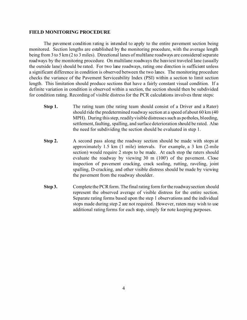
4
FIELD MONITORING PROCEDURE
The pavement condition rating is intended to apply to the entire pavement section beingmonitored. Section lengths are established by the monitoring procedure, with the average lengthbeing from 3 to 5 km (2 to 3 miles). Directional lanes of multilane roadways are considered separateroadways by the monitoring procedure. On multilane roadways the heaviest traveled lane (usuallythe outside lane) should be rated. For two lane roadways, rating one direction is sufficient unlessa significant difference in condition is observed between the two lanes. The monitoring procedurechecks the variance of the Pavement Serviceability Index (PSI) within a section to limit sectionlength. This limitation should produce sections that have a fairly constant visual condition. If adefinite variation in condition is observed within a section, the section should then be subdividedfor condition rating. Recording of visible distress for the PCR calculations involves three steps:
Step 1. The rating team (the rating team should consist of a Driver and a Rater)should ride the predetermined roadway section at a speed of about 60 km (40MPH). During this step, readily visible distresses such as potholes, bleeding,settlement, faulting, spalling, and surface deterioration should be rated. Alsothe need for subdividing the section should be evaluated in step 1.
Step 2. A second pass along the roadway section should be made with stops atapproximately 1.5 km (1 mile) intervals. For example, a 3 km (2-milesection) would require 2 stops to be made. At each stop the raters shouldevaluate the roadway by viewing 30 m (100') of the pavement. Closeinspection of pavement cracking, crack sealing, rutting, raveling, jointspalling, D-cracking, and other visible distress should be made by viewingthe pavement from the roadway shoulder.
Step 3. Complete the PCR form. The final rating form for the roadway section shouldrepresent the observed average of visible distress for the entire section.Separate rating forms based upon the step 1 observations and the individualstops made during step 2 are not required. However, raters may wish to useadditional rating forms for each stop, simply for note keeping purposes.

5
PAVEMENT CONDITION RATING FORMS AND KEY FORMS
Note: The Key forms summarize data presented in Appendices A through D. These key formswill aid field personnel in establishing distress severity and extent while performing the PCRsurveys.
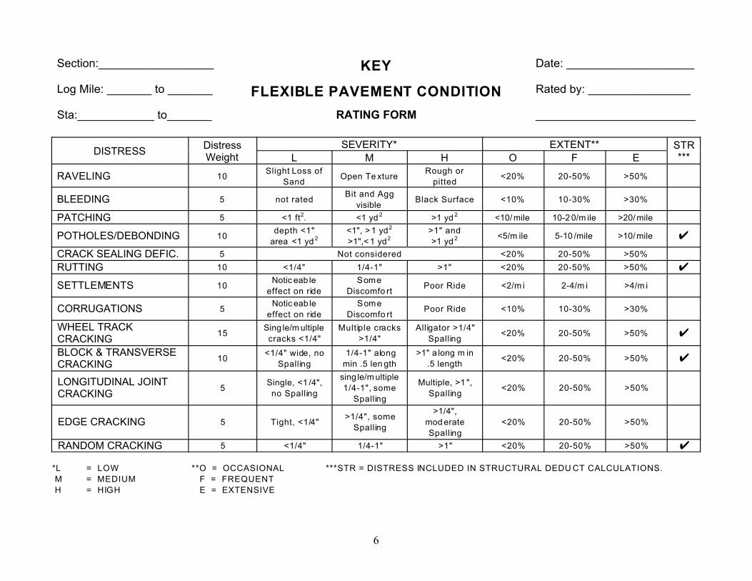
6
Section:__________________ KEY Date: ____________________
Log Mile: _______ to _______ FLEXIBLE PAVEMENT CONDITION Rated by: ________________
Sta:____________ to_______ RATING FORM _________________________
DISTRESSDistressWeight
SEVERITY* EXTENT** STR***L M H O F E
RAVELING 10Slight Loss of
SandOpen Te xture
Rough or
pitted<20% 20-50% >50%
BLEEDING 5 not ratedBit and Agg
visibleBlack Surface <10% 10-30% >30%
PATCHING 5 <1 ft2. <1 yd 2 >1 yd 2 <10/ mile 10-2 0/m ile >20/ mile
POTHOLES/DEBONDING 10depth <1"
area <1 yd 2<1", > 1 yd2
>1",< 1 yd2>1" and
>1 yd 2 <5/m ile 5-10 /mile >10/ mile U
CRACK SEALING DEFIC. 5 Not considered <20% 20-50% >50%
RUTTING 10 <1/4" 1/4-1" >1" <20% 20-50% >50% U
SETTLEMENTS 10Notic eab le
effect on ride
Some
Discomfo rtPoor Ride <2/m i 2-4/m i >4/m i
CORRUGATIONS 5Notic eab le
effect on ride
Some
Discomfo rtPoor Ride <10% 10-30% >30%
WHEEL TRACKCRACKING
15Sing le/m ultiple
cracks <1/4"
Multiple cracks
>1/4"
Alligator >1/4"
Spalling<20% 20-50% >50% U
BLOCK & TRANSVERSECRACKING
10<1/4" wide, no
Spalling
1/4-1" along
min .5 len gth
>1" a long m in
.5 length<20% 20-50% >50% U
LONGITUDINAL JOINTCRACKING
5Single, <1 /4",
no Spalling
sing le/m ultiple
1/4-1", some
Spalling
Multiple, >1 ",
Spalling<20% 20-50% >50%
EDGE CRACKING 5 Tight, <1/4">1/4", some
Spalling
>1/4",
mod erate
Spalling
<20% 20-50% >50%
RANDOM CRACKING 5 <1/4" 1/4-1" >1" <20% 20-50% >50% U
*L = LOW **O = OCCASIONAL ***STR = DISTRESS INCLUDED IN STRUCTURAL DEDU CT CALCULATIONS.
M = MEDIUM F = FREQUENT
H = HIGH E = EXTENSIVE

7
Section: __________________
FLEXIBLEDate: ____________________
Log mile: ______ to_________ Rated by: ________________
Sta: __________ to_________ _________________________
PAVEMENT CONDITION RATING FORM
DISTRESSDISTRESSWEIGHT
SEVERITY WT.* EXTENT WT.** DEDUCTPOINTS***L M H O F E
RAVELING 10 0.3 0.6 1 0.5 0.8 1
BLEEDING 5 0.8 0.8 1 0.6 0.9 1
PATCHING 5 0.3 0.6 1 0.6 0.8 1
POTHOLES/DEBONDING 10 0.4 0.7 1 0.5 0.8 1 T
CRACK SEALING DEFICIENCY 5 1 1 1 0.5 0.8 1
RUTTING 10 0.3 0.7 1 0.6 0.8 1 T
SETTLEMENT 10 0.5 0.7 1 0.5 0.8 1
CORRUGATIONS 5 0.4 0.8 1 0.5 0.8 1
WHEEL TRACK CRACKING 15 0.4 0.7 1 0.5 0.7 1 T
BLOCK AND TRANSVERSE CRACKING 10 0.4 0.7 1 0.5 0.7 1 T
LONGITUDINAL JOINT CRACKING 5 0.4 0.7 1 0.5 0.7 1
EDGE CRACKING 5 0.4 0.7 1 0.5 0.7 1
RANDOM CRACKING 5 0.4 0.7 1 0.5 0.7 1 T
*L = LOW **O = OCCASIONAL TOTAL DEDUCT =
M = MEDIUM F = FREQUENT SUM OF STRUCTURAL DEDUCT (T) =
H = HIGH E = EXTENSIVE 100 - TOTAL DEDUCT = PCR =
*** DEDUCT POINTS = DISTRESS WEIGHT X SEVERITY WT. X EXTENT WT.
REMARKS:
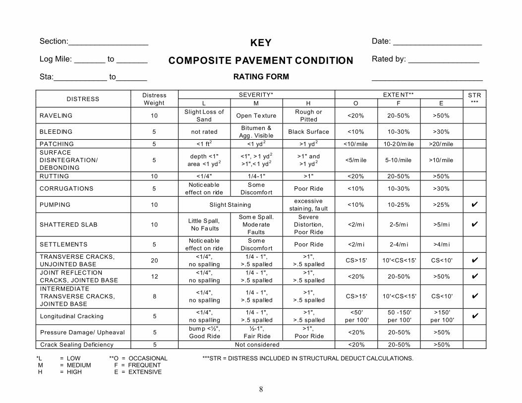
8
Section:__________________ KEY Date: ____________________
Log Mile: _______ to _______ COMPOSITE PAVEMENT CONDITION Rated by: ________________
Sta:____________ to_______ RATING FORM _________________________
DISTRESSDistress
Weight
SEVERITY* EXTE NT** STR
***L M H O F E
RAVELING 10Slight Loss of
SandOpen Te xture
Rough or
Pitted<20% 20-50% >50%
BLEEDING 5 not ratedBitumen &
Agg . Visib leBlack Surface <10% 10-30% >30%
PATCHING 5 <1 ft2 <1 yd 2 >1 yd 2 <10/ mile 10-2 0/m ile >20/ mile
SURFACE
DISINTEGRATION/
DEBONDING
5depth <1"
area <1 yd 2<1", > 1 yd2
>1",< 1 yd2>1" and
>1 yd 2 <5/m ile 5-10 /mile >10/ mile
RUTTING 10 <1/4" 1/4-1" >1" <20% 20-50% >50%
CORRUGATIONS 5Notic eab le
effect on ride
Some
Discomfo rtPoor Ride <10% 10-30% >30%
PUMPING 10 Slight Stainingexcessive
stain ing, fa ult<10% 10-25% >25% U
SHATTERED SLAB 10Little S pall,
No Fa ults
Som e Spall.
Mode rate
Faults
Severe
Distortion,
Poor Ride
<2/m i 2-5/m i >5/m i U
SETTLEMENTS 5Notic eab le
effect on ride
Some
Discomfo rtPoor Ride <2/m i 2-4/m i >4/m i
TRANSVERSE CRACKS,
UNJOINTED BASE20
<1/4",
no spalling
1/4 - 1",
>.5 spalled
>1",
>.5 spalledCS>15' 10'<CS<15' CS<10' U
JOINT REFLECTION
CRACKS, JOINTED BASE12
<1/4",
no spalling
1/4 - 1",
>.5 spalled
>1",
>.5 spalled<20% 20-50% >50% U
INTERMEDIATE
TRANSVERSE CRACKS,
JOINTED BASE
8<1/4",
no spalling
1/4 - 1",
>.5 spalled
>1",
>.5 spalledCS>15' 10'<CS<15' CS<10' U
Longitudinal Cracking 5<1/4",
no spalling
1/4 - 1",
>.5 spalled
>1",
>.5 spalled
<50'
per 100'
50 -150'
per 100'
>150'
per 100'U
Pressure Damage/ Upheaval 5bum p <½",
Good Ride
½-1",
Fair Ride
>1",
Poor Ride<20% 20-50% >50%
Crack Sealing Deficiency 5 Not considered <20% 20-50% >50%
*L = LOW **O = OCCASIONAL ***STR = DISTRESS INCLUDED IN STRUCTURAL DEDUCT CALCULATIONS. M = MEDIUM F = FREQUENT H = HIGH E = EXTENSIVE

9
Section: __________________
COMPOSITEDate: ____________________
Log mile: ______ to_________ Rated by: ________________
Sta: __________ to_________ _________________________
PAVEMENT CONDITION RATING FORM
DISTRESSDISTRESSWEIGHT
SEVERITY WT.* EXTENT WT.** DEDUCTPOINTS***L M H O F E
RAVELING 10 0.3 0.6 1 0.5 0.8 1
BLEEDING 5 0.8 0.8 1 0.6 0.9 1
PATCHING 5 0.3 0.6 1 0.6 0.8 1
SURFACE DISINTEGRATION or DEBONDING 5 0.3 0.6 1 0.6 0.8 1
RUTTING 10 0.3 0.7 1 0.6 0.8 1
CORRUGATIONS 5 0.4 0.8 1 0.5 0.8 1
PUMPING 10 0.7 0.7 1 0.3 0.7 1 T
SHATTERED SLAB 10 0.6 0.8 1 0.7 0.9 1 T
SETTLEMENTS 5 0.4 0.7 1 0.6 0.8 1
TRANSVERSE CRACKS, UNJOINTED BASE 20 0.2 0.6 1 0.4 0.8 1 T
JOINT REFLECTION CRACKS, JOINTED BASE 12 0.2 0.6 1 0.4 0.8 1 T
INTERMEDIATE TRANSVERSE CRACKS,JOINTED BASE
8 0.2 0.6 1 0.4 0.8 1 T
LONGITUDINAL CRACKING 5 0.2 0.6 1 0.4 0.8 1 T
PRESSURE DAMAGE/UPHEAVAL 5 0.4 0.6 1 0.5 0.8 1
CRACK SEALING DEFICIENCY 5 1 1 1 0.5 0.8 1
*L = LOW **O = OCCASIONAL TOTAL DEDUCT =
M = MEDIUM F = FREQUENT SUM OF STRUCTURAL DEDUCT (T) =
H = HIGH E = EXTENSIVE 100 - TOTAL DEDUCT = PCR =
*** DEDUCT POINTS = DISTRESS WEIGHT X SEVERITY WT. X EXTENT WT.
REMARKS:
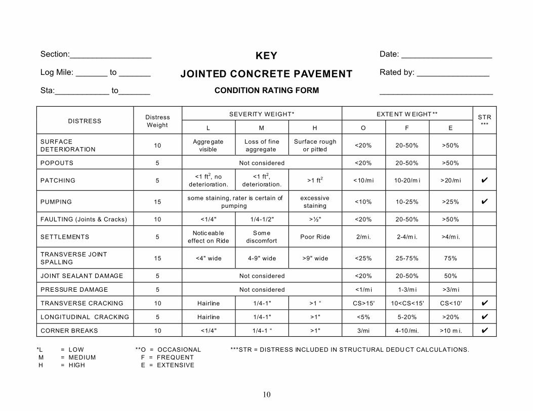
10
Section:__________________ KEY Date: ____________________
Log Mile: _______ to _______ JOINTED CONCRETE PAVEMENT Rated by: ________________
Sta:____________ to_______ CONDITION RATING FORM _________________________
DISTRESSDistress
Weight
SEVERITY WEIGHT* EXTE NT W EIGHT ** STR
***L M H O F E
SURFACE
DETERIORATION10
Aggre gate
visible
Loss of fine
aggregate
Surface rough
or pitted<20% 20-50% >50%
POPOUTS 5 Not considered <20% 20-50% >50%
PATCHING 5<1 ft2, no
deterioration.
<1 ft2,
deterioration.>1 ft2 <10/mi 10-20/m i >20/mi U
PUMPING 15some staining, rater is certain of
pumping
excessive
staining<10% 10-25% >25% U
FAULTING (Joints & Cracks) 10 <1/4" 1/4-1/2" >½" <20% 20-50% >50%
SETTLEMENTS 5Notic eab le
effect on Ride
Some
discomfortPoor Ride 2/m i. 2-4/m i. >4/m i.
TRANSVERSE JOINT
SPALLING15 <4" wide 4-9" wide >9" wide <25% 25-75% 75%
JOINT SEALANT DAMAGE 5 Not considered <20% 20-50% 50%
PRESSURE DAMAGE 5 Not considered <1/m i 1-3/m i >3/m i
TRANSVERSE CRACKING 10 Hairline 1/4-1" >1 “ CS>15' 10<CS<15' CS<10' U
LONGITUDINAL CRACKING 5 Hairline 1/4-1" >1" <5% 5-20% >20% U
CORNER BREAKS 10 <1/4" 1/4-1 “ >1" 3/mi 4-10 /mi. >10 m i. U
*L = LOW **O = OCCASIONAL ***STR = DISTRESS INCLUDED IN STRUCTURAL DEDU CT CALCULATIONS.
M = MEDIUM F = FREQUENT
H = HIGH E = EXTENSIVE

11
Section: __________________
JOINTED CONCRETEDate: ____________________
Log mile: ______ to_________ Rated by: ________________
Sta: __________ to_________ _________________________
PAVEMENT CONDITION RATING FORM
DISTRESSDISTRESSWEIGHT
SEVERITY WT.* EXTENT WT.** DEDUCTPOINTS***L M H O F E
SURFACE DETERIORATION 10 0.4 0.7 1 0.6 0.8 1
POPOUT 5 1 1 1 0.4 0.6 1
PATCHING 5 0.4 0.7 1 0.5 0.8 1
PUMPING 15 0.7 0.7 1 0.3 0.7 1 T
FAULTING (JOINTS AND CRACKS) 10 0.4 0.7 1 0.5 0.8 1 T
SETTLEMENTS 5 0.4 0.7 1 0.5 0.8 1
TRANSVERSE JOINT SPALLING (CIRCLE IF D-CRACKED)
15 0.4 0.7 1 0.5 0.8 1
JOINT SEALANT DAMAGE 5 1 1 1 0.5 0.8 1
PRESSURE DAMAGE 5 1 1 1 0.5 0.8 1
TRANSVERSE CRACKING 10 0.3 0.8 1 0.4 0.8 1 T
LONGITUDINAL CRACKING 5 0.5 0.7 1 0.4 0.9 1
CORNER BREAKS 10 0.4 0.8 1 0.5 0.8 1 T
*L = LOW **O = OCCASIONAL TOTAL DEDUCT =
M = MEDIUM F = FREQUENT SUM OF STRUCTURAL DEDUCT (T) =
H = HIGH E = EXTENSIVE 100 - TOTAL DEDUCT = PCR =
*** DEDUCT POINTS = DISTRESS WEIGHT X SEVERITY WT. X EXTENT WT.
REMARKS:
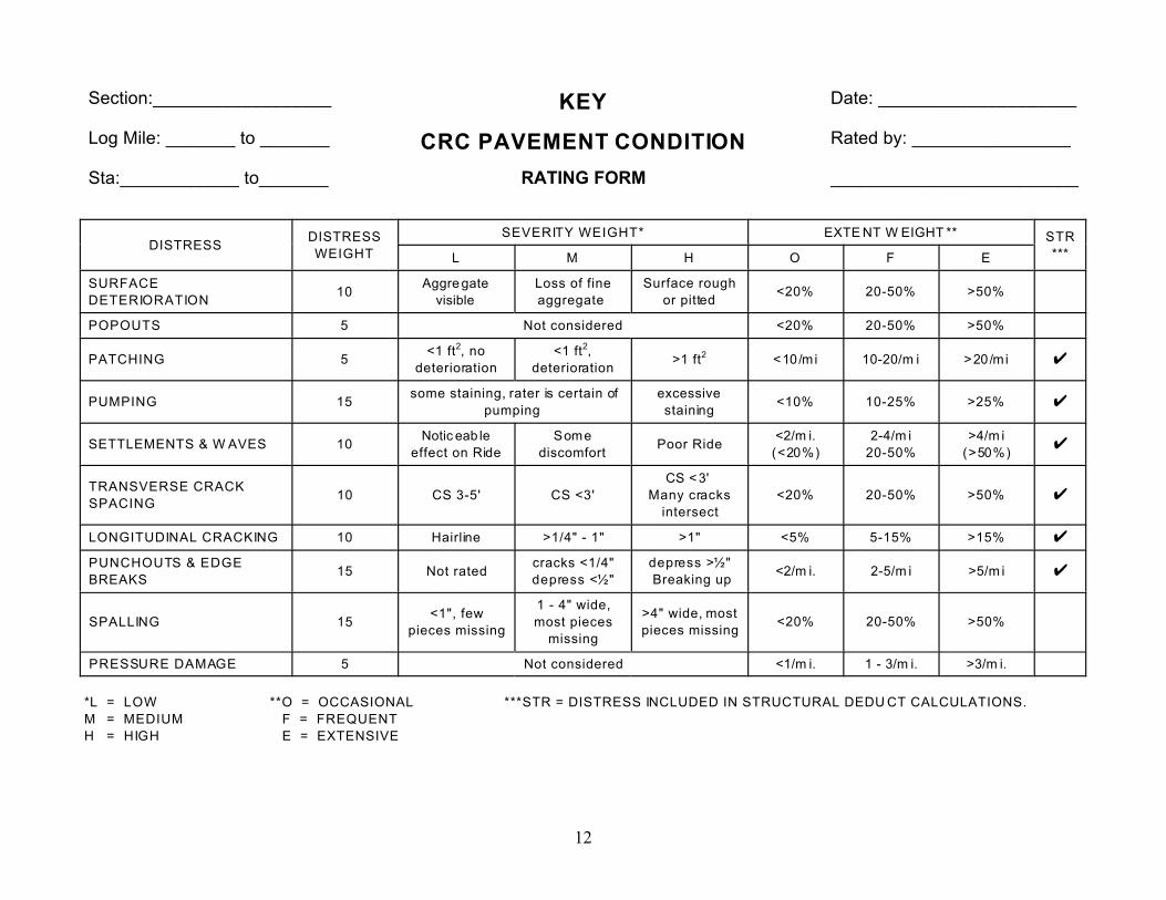
12
Section:__________________ KEY Date: ____________________
Log Mile: _______ to _______ CRC PAVEMENT CONDITION Rated by: ________________
Sta:____________ to_______ RATING FORM _________________________
DISTRESSDISTRESS
WEIGHT
SEVERITY WEIGHT* EXTE NT W EIGHT ** STR
***L M H O F E
SURFACE
DETERIORATION10
Aggre gate
visible
Loss of fine
aggregate
Surface rough
or pitted<20% 20-50% >50%
POPOUTS 5 Not considered <20% 20-50% >50%
PATCHING 5<1 ft2, no
deterioration
<1 ft2,
deterioration>1 ft2 <10/mi 10-20/m i >20/mi U
PUMPING 15some staining, rater is certain of
pumping
excessive
staining<10% 10-25% >25% U
SETTLEMENTS & W AVES 10Notic eab le
effect on Ride
Some
discomfortPoor Ride
<2/m i.
(<20%)
2-4/m i
20-50%
>4/m i
(>50%)U
TRANSVERSE CRACK
SPACING10 CS 3-5' CS <3'
CS < 3'
Many cracks
intersect
<20% 20-50% >50% U
LONGITUDINAL CRACKING 10 Hairline >1/4" - 1" >1" <5% 5-15% >15% U
PUNCHOUTS & EDGE
BREAKS15 Not rated
cracks <1/4"
depress <½"
depress >½"
Breaking up<2/m i. 2-5/m i >5/m i U
SPALLING 15<1", few
pieces missing
1 - 4" wide,
most pieces
missing
>4" wide, most
pieces missing<20% 20-50% >50%
PRESSURE DAMAGE 5 Not considered <1/m i. 1 - 3/m i. >3/m i.
*L = LOW **O = OCCASIONAL ***STR = DISTRESS INCLUDED IN STRUCTURAL DEDU CT CALCULATIONS.
M = MEDIUM F = FREQUENT
H = HIGH E = EXTENSIVE
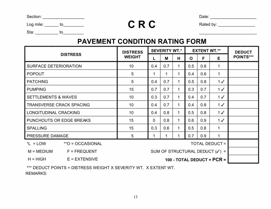
13
Section: __________________
C R CDate: ____________________
Log mile: ______ to_________ Rated by: ________________
Sta: __________ to_________ _________________________
PAVEMENT CONDITION RATING FORM
DISTRESSDISTRESSWEIGHT
SEVERITY WT.* EXTENT WT.** DEDUCTPOINTS***L M H O F E
SURFACE DETERIORATION 10 0.4 0.7 1 0.5 0.8 1
POPOUT 5 1 1 1 0.4 0.6 1
PATCHING 5 0.4 0.7 1 0.5 0.8 1 T
PUMPING 15 0.7 0.7 1 0.3 0.7 1 T
SETTLEMENTS & WAVES 10 0.3 0.7 1 0.4 0.7 1 T
TRANSVERSE CRACK SPACING 10 0.4 0.7 1 0.4 0.8 1 T
LONGITUDINAL CRACKING 10 0.4 0.8 1 0.5 0.8 1 T
PUNCHOUTS OR EDGE BREAKS 15 0 0.8 1 0.6 0.9 1 T
SPALLING 15 0.3 0.6 1 0.5 0.8 1
PRESSURE DAMAGE 5 1 1 1 0.7 0.9 1
*L = LOW **O = OCCASIONAL TOTAL DEDUCT =
M = MEDIUM F = FREQUENT SUM OF STRUCTURAL DEDUCT (T) =
H = HIGH E = EXTENSIVE 100 - TOTAL DEDUCT = PCR =
*** DEDUCT POINTS = DISTRESS WEIGHT X SEVERITY WT. X EXTENT WT.
REMARKS:

A-1
APPENDIX A
Description of Distresses in Flexible Pavements

A-2
FLEXIBLE PAVEMENT
Distress Type: Raveling
Description: Disintegration of the pavement from the surface downward due to the loss ofaggregate particles. Raveling may occur as a result of asphalt binder aging,poor mixture quality, segregation, or insufficient compaction.
Severity Level: Low-- Very little coarse aggregate has worn away. Loss of fineaggregate. Coarse aggregate exposed.
Medium-- Surface has an open texture and is moderately rough withconsiderable loss of fine aggregate and some coarse aggregateremoved.
High-- Most of the surface aggregate has worn away or becomedislodged. Surface is severely rough and pitted and may becompletely removed in places.
Extent Level: Occasional-- Less than 20 percent of the surface area is raveling.
Frequent-- Between 20 and 50 percent of the surface area is raveling.
Extensive-- More than 50 percent of the surface area is raveling.

A-3
Photo A-1. Raveling in Flexible Pavement, Medium Severity
Photo A-2. Raveling in Flexible Pavement, High Severity

A-4
FLEXIBLE PAVEMENT
Distress Type: Bleeding
Description: Bleeding or flushing is the presence of free asphalt binder on the pavementsurface. Bleeding is caused by an excess amount of bituminous binder in themixture and/or low air void content.
Severity Level: Only 2 severity levels are defined.
Medium-- both coarse aggregate and free bitumen are noticeable at thepavement surface.
High-- surface appears black with very little aggregate noticeable.
Extent Level: Occasional-- less than 10 percent of the length exhibits bleeding.
Frequent-- between 10 and 30 percent of the length is bleeding.
Extensive-- bleeding occurs in more than 30 percent of the length.

A-5
Photo A-3. Bleeding in Flexible Pavement, High Severity
Photo A-4. Close-up view of Bleeding, High and Medium SeverityHigh Sev erity on left show s most aggreg ates covered with aspha lt and M edium Sever ity on right show s less
aggre gates co vered w ith aspha lt
A-6
FLEXIBLE PAVEMENT
Distress Type: Patching
Description: Patching is either the placing of asphalt concrete on the surface of the existingpavement or the replacement of the existing pavement in small isolated areas.
Deductions shall be made for all patches present in the pavement which arethe result of deterioration and/or maintenance since the last constructionproject.
Large patched areas [greater than 12.5 m2 (15 sq. yd.)], such as spot overlaysor wedge courses, shall be rated for condition as a part of the existingpavement rather than as patches.
Severity Level: Low-- patch size < 0.1 m2 (1 sq. ft.).
Medium-- patch size < 0.8 m2 (1 sq. yd.).
High-- patch size > 0.8 m2 (1 sq. yd.).
Extent Level: Occasional-- < 10 patches/1.6 km (per mile).
Frequent-- 10 - 20 patches/1.6 km (per mile).
Extensive-- > 20 patches/1.6 km (per mile).

A-7
Photo A-5. Patching in Flexible Pavement, High Severity
Photo A-6. Patching in Flexible Pavement, High Severity
A-8
FLEXIBLE PAVEMENT
Distress Type: Potholes/Debonding
Description: Potholes are bowl-shaped voids or depressions in the pavement surface.Potholes are localized failure areas which are usually caused by weak base orsubgrade layers.
Loss of surface by debonding is the removal of the asphaltic surface layerfrom the underlying layer. The problem is most common with thin asphaltsurface layers [less than 50 mm (2 inches)] and is caused by freeze-thawaction or poor bonding of the two layers during construction.
Severity Level: Use the following table to determine the severity levels:
Depth of DebondedArea
Debonded Area<0.8 m2 (1 sq. yd.)
Debonded Area>0.8 m2 (1 sq. yd.)
< 25 mm (1") Low Medium
> 25 mm (1") Medium High
Regardless of depth, potholes less than 150 mm (6 inches) in diameter shallbe considered to be of low severity.
Extent Level: Occasional-- < 5 potholes/1.6 km (per mile).
Frequent-- 5 - 10 potholes/1.6 km (per mile).
Extensive-- > 10 potholes/1.6 km (per mile).

A-9
Photo A-7. Pothole in Flexible Pavement, Medium Severity
Photo A-8. Debonding in Flexible Pavement, Medium Severity

A-10
FLEXIBLE PAVEMENT
Distress Type: Crack Sealing Deficiency
Description: Crack sealing deficiency is crack sealing which is no longer effective inpreventing intrusion of water or cracks which have never been sealed.
Severity Level: Severity levels are not considered.
Extent Level: Occasional-- less than 20 percent of the cracks along the pavement sectionare not effectively sealed.
Frequent– between 20 and 50 percent of the cracks along the pavementsection are not effectively sealed.
Extensive-- more than 50 percent of the cracks along the pavement sectionare not effectively sealed.

A-11
Photo A-9. Crack Sealing Deficiency in Flexible Pavement, Unsealed Cracks
Photo A-10. Crack sealing Deficiency in Flexible Pavement, Cracks not sealed properly

A-12
FLEXIBLE PAVEMENT
Distress Type: Rutting
Description: Ruts are vertical deformations in the pavement surface along the wheeltracks. In severe cases pavement uplift may occur along the sides of the rut,but in most instances only a depression is noticeable. Rutting is caused byconsolidation or lateral movement of any or all pavement layers, includingsubgrade, under traffic.
Severity Level: Rutting severity is based upon rut depth, as approximated visually.
Low-- barely noticeable, depth less than 6 mm (1/4 inch).
Medium-- readily noticeable, depth more than 6 mm (1/4 inch), less than25 mm (1 inch).
High-- definite effect upon vehicle control, depth greater than 25 mm(1 inch).
Extent Level: Occasional-- less than 20 percent of the section length is rutted.
Frequent-- between 20 and 50 percent of the section length is rutted.
Extensive-- more than 50 percent of the section length is rutted.

A-13
Photo A-11. Rutting in Flexible Pavement, Medium Severity
Photo A-12. Rutting in Flexible Pavement, High Severity

A-14
FLEXIBLE PAVEMENT
Distress Type: Settlement
Description: Settlement is a dip in the longitudinal profile of the pavement surface.Settlement shall be considered a distress when it causes a noticeable effectupon riding quality. Settlement should not be confused with corrugation,which is another type of surface profile deficiency.
Severity Level: Severity is based upon the effect of the settlement on vehicle control whentraveling along the roadway at 60 km/hour (40 MPH), as discussed in step 1of the monitoring procedure.
Low-- noticeable effect upon ride, driver able to maintain vehiclecontrol easily.
Medium-- some discomfort to passengers, driver able to maintain controlwith slight corrective action.
High-- definite effect upon ride quality, noticeable profile dipgenerally greater than 150 mm (6 inches). Poor ride,corrective action needed.
Extent Level: Occasional-- less than 2 settlements/1.6 km (per mile) of roadway.
Frequent-- 2 to 4 settlements/1.6 km (per mile) of roadway.
Extensive-- more than 4 settlements/1.6 km (per mile) of roadway.

A-15
Photo A-13. Settlement, Low Severity
Photo A-14. Settlement, Medium Severity

A-16
FLEXIBLE PAVEMENT
Distress Type: Corrugations
Description: Corrugations are a series of transverse ridges and valleys (or ripples)occurring at regular intervals along the pavement. Unstable bituminousmixture or poor base quality are associated with this distress.
Severity Level: Low-- noticeable effect upon ride, but no significant reduction incomfort.
Medium-- moderate ride discomfort is noticeable, driver able to maintainvehicle control easily.
High-- vehicle vibration is severe, speed reduction is necessary forcomfort and to maintain vehicle control.
Extent Level: Occasional-- less than 10 percent of the section length is affected by thisdistress.
Frequent-- between 10 and 30 percent of the section length is affected bythis distress.
Extensive-- greater than 30 percent of the section length is affected by thisdistress.
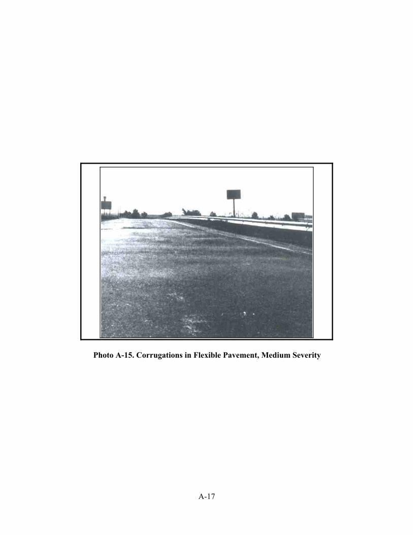
A-17
Photo A-15. Corrugations in Flexible Pavement, Medium Severity

A-18
FLEXIBLE PAVEMENT
Distress Type: Wheel Track Cracking
Description: Cracks located within or near the wheel tracks. For evaluation purposes eachwheel track shall be considered 1 m (3 feet) in width. Wheel track crackingusually starts as intermittent, single longitudinal cracks progressing tomultiple longitudinal cracking, and eventually interconnected or alligatorcracking. Wheel track cracking usually results from fatigue failure of theasphaltic layer.
Severity Level: Severity is based upon both crack width and multiplicity of the cracking.Both criteria must be satisfied when assigning severity level.
Low-- single or intermittent multiple cracking with average crackwidth less than 6 mm (1/4 inch).
Medium-- single or multiple cracking (may also include regions ofintermittent alligator cracking) with average crack widthgreater than 6 mm (1/4 inch) with little spalling or loosepieces.
High-- multiple cracking with extensive alligator cracking. Spallingis fairly common, with average crack width greater than 6 mm(1/4 inch), and some alligator blocks are easily removed.
Extent Level: Extent is based upon percentage of the wheel track length within the sectionwhich exhibits cracking.
Occasional-- less than 20 percent.
Frequent-- between 20 and 50 percent.
Extensive-- more than 50 percent.
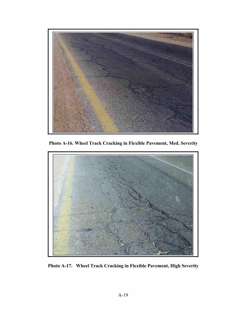
A-19
Photo A-16. Wheel Track Cracking in Flexible Pavement, Med. Severity
Photo A-17. Wheel Track Cracking in Flexible Pavement, High Severity

A-20
FLEXIBLE PAVEMENT
Distress Type: Block and Transverse Cracking
Description: Block cracks are interconnected cracks which divide the pavement into largerectangular pieces or blocks. Block size may range from 1 m by 1 m (3 ft. by3 ft.) upwards to 3 m by 3 m (10 ft. by 10 ft.). Transverse cracking is cracksat approximately right angles to the pavement centerline. The occurrence ofboth block and/or transverse cracking is usually related to thermal shrinkageof the asphalt binder. Binder age hardening is also related to formation ofthese crack types.
Severity Level: Low-- average crack width less than 6 mm (1/4 inch) with nospalling or distortion along crack edges.
Medium-- average crack opened or spalled to a width between 6 mm to25 mm (1/4 to 1 inch) along at least half its length.
High-- average crack opened or spalled to a width greater than 25mm (1 inch) along at least half its length.
Extent Level: Occasional-- less than 20 percent of the section length is affected by thisdistress.
Frequent-- between 20 and 50 percent of this section length is affected bythis distress.
Extensive-- greater than 50 percent of the section length is affected by thisdistress.
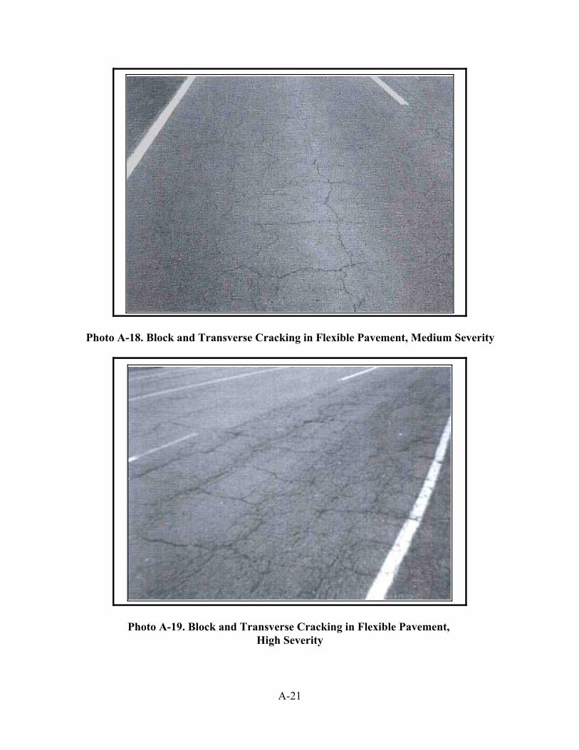
A-21
Photo A-18. Block and Transverse Cracking in Flexible Pavement, Medium Severity
Photo A-19. Block and Transverse Cracking in Flexible Pavement, High Severity

A-22
FLEXIBLE PAVEMENT
Distress Type: Longitudinal Joint Cracking
Description: Deterioration or cracking of the longitudinal joints formed by separate passesof an asphalt paver, including shoulders and widening. Poor compactionalong the longitudinal joint often results in the disintegration of materialalong the joint and may be accompanied by single or multiple cracking.
Severity Level: Low-- single longitudinal crack with width less than 6 mm (1/4")and no spalling.
Medium-- single or multiple cracking 6 mm - 25 mm (1/4"-1") withsome spalling.
High-- multiple cracking > 25 mm (1") wide with much spalling.
Extent Level: Occasional-- less than 20%.
Frequent-- between 20 and 50%.
Extensive-- more than 50%.

A-23
Photo A-20. Longitudinal Joint Cracking in Flexible Pavement, Medium Severity
Photo A-21. Longitudinal Joint Cracking in Flexible Pavement, High Severity

A-24
FLEXIBLE PAVEMENT
Distress Type: Edge Cracking
Description: Edge cracks are longitudinal or crescent shaped cracks usually within 0.3 m(1 foot) of the pavement edge line.
Severity Level: Low-- tight cracks, width less than 6 mm (1/4 inch) with no break upor spalling.
Medium-- crack width greater than 6 mm (1/4 inch) with some spalling.
High-- multiple cracking with moderate spalling and average crackwidth greater than 6 mm (1/4 inch).
Extent Level: Occasional-- cracking occurs along less than 20 percent of the pavementedge within the section.
Frequent-- cracking occurs along 20 to 50 percent of the pavement edgewithin the section.
Extensive-- cracking occurs along more than 50 percent of the pavementedge within the section.

A-25
Photo A-22. Edge Cracking in Flexible Pavement, Medium Severity
Photo A-23. Edge Cracking in Flexible Pavement, High Severity
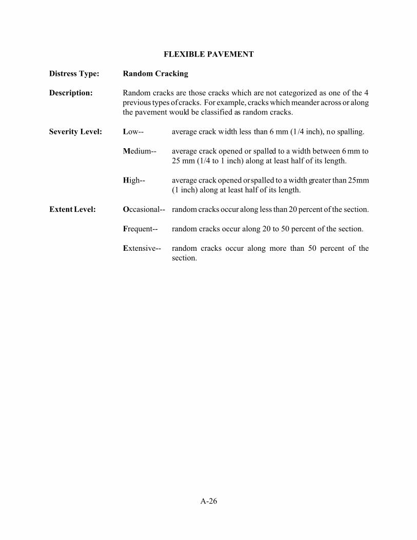
A-26
FLEXIBLE PAVEMENT
Distress Type: Random Cracking
Description: Random cracks are those cracks which are not categorized as one of the 4previous types of cracks. For example, cracks which meander across or alongthe pavement would be classified as random cracks.
Severity Level: Low-- average crack width less than 6 mm (1/4 inch), no spalling.
Medium-- average crack opened or spalled to a width between 6 mm to25 mm (1/4 to 1 inch) along at least half of its length.
High-- average crack opened or spalled to a width greater than 25mm(1 inch) along at least half of its length.
Extent Level: Occasional-- random cracks occur along less than 20 percent of the section.
Frequent-- random cracks occur along 20 to 50 percent of the section.
Extensive-- random cracks occur along more than 50 percent of thesection.

A-27
Photo A-24. Random Cracking in Flexible Pavement, Medium Severity

B-1
APPENDIX B
Description of Distresses in Composite Pavements
[Composite Pavements have rigid bases (concrete or brick) and asphaltic surfaces]

B-2
COMPOSITE PAVEMENT
Distress Type: Raveling
Description: Disintegration of the pavement from the surface downward due to the loss ofaggregate particles. Raveling may occur as a result of asphalt binder aging,poor mixture quality segregation, or insufficient compaction.
Severity Level: Low-- very little coarse aggregate has worn away. Loss of fineaggregate. Coarse aggregate exposed.
Medium-- surface has an open texture and is moderately rough withconsiderable loss of fine aggregate and some coarse aggregateremoved.
High-- most of the surface aggregate has worn away or becomedislodged. Surface is severely rough and pitted and may becompletely removed in places.
Extent Level: Occasional-- less than 20 percent of the surface area is raveling.
Frequent-- between 20 and 50 percent of the surface area is raveling.
Extensive-- more than 50 percent of the surface area is raveling.
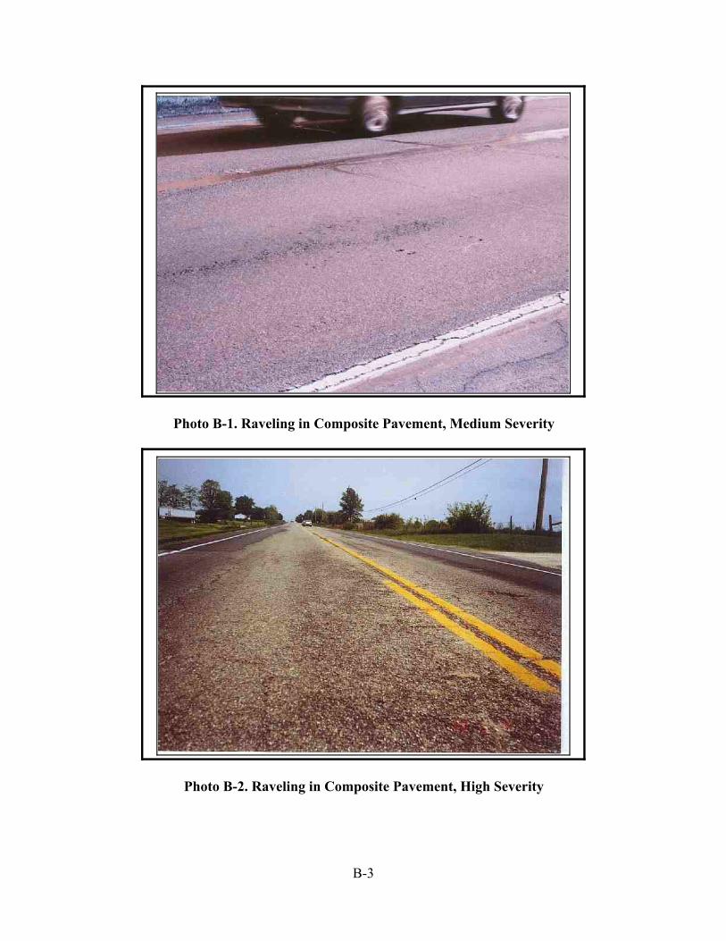
B-3
Photo B-1. Raveling in Composite Pavement, Medium Severity
Photo B-2. Raveling in Composite Pavement, High Severity

B-4
COMPOSITE PAVEMENT
Distress Type: Bleeding
Description: Bleeding or flushing is the presence of free asphalt binder on the pavementsurface. Bleeding is caused by an excess amount of bituminous binder in themixture and/or low air void content.
Severity Level: Only 2 severity levels are defined.
Medium-- both coarse aggregate and free bitumen are noticeable at thepavement surface.
High-- surface appears black with very little aggregate noticeable.
Extent Level: Occasional-- less than 10 percent of the length exhibits bleeding.
Frequent-- between 10 and 30 percent of the length is bleeding.
Extensive-- bleeding occurs in more than 30 percent of the length.

B-5
Photo B-3. Bleeding, High Severity
Photo B-4. Close-up view of Bleeding, High and Medium SeverityHigh Severity on left show s most aggregates covered w ith asphalt and Med ium Severity
on right shows less aggregates cov ered with asphalt
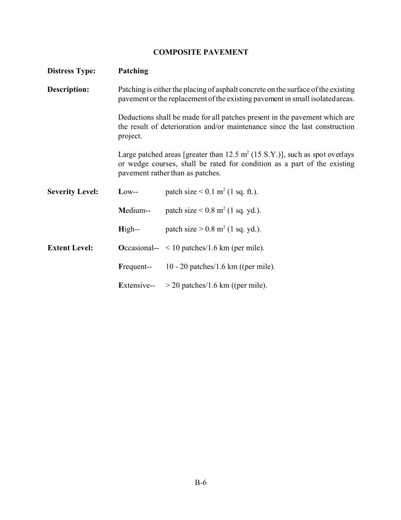
B-6
COMPOSITE PAVEMENT
Distress Type: Patching
Description: Patching is either the placing of asphalt concrete on the surface of the existingpavement or the replacement of the existing pavement in small isolated areas.
Deductions shall be made for all patches present in the pavement which arethe result of deterioration and/or maintenance since the last constructionproject.
Large patched areas [greater than 12.5 m2 (15 S.Y.)], such as spot overlaysor wedge courses, shall be rated for condition as a part of the existingpavement rather than as patches.
Severity Level: Low-- patch size < 0.1 m2 (1 sq. ft.).
Medium-- patch size < 0.8 m2 (1 sq. yd.).
High-- patch size > 0.8 m2 (1 sq. yd.).
Extent Level: Occasional-- < 10 patches/1.6 km (per mile).
Frequent-- 10 - 20 patches/1.6 km ((per mile).
Extensive-- > 20 patches/1.6 km ((per mile).

B-7
Photo B-5. Patching in Composite Pavement, Medium Severity
Photo B-6. Patching in Composite Pavement, High Severity

B-8
COMPOSITE PAVEMENT
Distress Type: Surface Disintegration or Debonding
Description: Loss of surface by debonding is the removal of the asphaltic surface layerfrom the underlying layer. The problem is most common with thin asphaltsurface layers [less than 50 mm (2 inches)] and is caused by freeze-thawaction or poor bonding of the two layers during construction.
Severity Level: Use the following table:
Depth of Debonded AreaDebonded Area
<0.8 m2 (1 sq. yd.)Debonded Area
>0.8 m2 (1 sq. yd.)
< 25 mm (1") Low Medium
> 25 mm (1") Medium High
Extent Level: Occasional-- <5 debonded areas per 1.6 km (per mile).
Frequent-- 5 - 10 debonded areas per 1.6 km (per mile).
Extensive-- >10 debonded areas per 1.6 km (per mile).
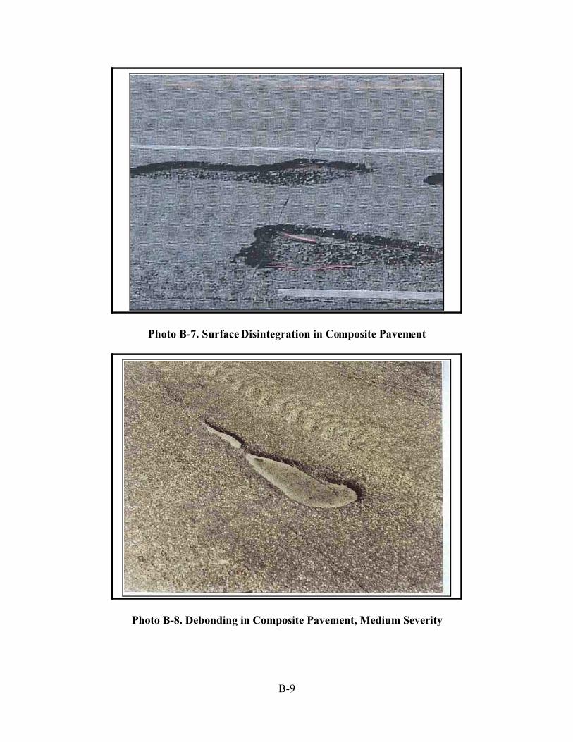
B-9
Photo B-7. Surface Disintegration in Composite Pavement
Photo B-8. Debonding in Composite Pavement, Medium Severity

B-10
COMPOSITE PAVEMENT
Distress Type: Rutting
Description: Ruts are vertical deformations in the pavement surface along the wheeltracks. In severe cases pavement uplift may occur along the sides of the rut,but in most instances only a depression is noticeable. Rutting is caused byconsolidation or lateral movement of any or all pavement layers, includingsubgrade, under traffic.
Severity Level: Rutting severity is based upon rut depth, as approximated visually.
Low-- barely noticeable, depth less than 6 mm (1/4 inch).
Medium-- readily noticeable, depth more than 6 mm (1/4 inch), less than25 mm (1 inch).
High-- definite effect upon vehicle control, depth greater than 25 mm(1 inch).
Extent Level: Occasional-- less than 20 percent of the section length is rutted.
Frequent-- between 20 and 50 percent of the section length is rutted.
Extensive-- more than 50 percent of the section length is rutted.

B-11
Photo B-9. Rutting, Medium Severity
Photo B-10. Rutting, High Severity

B-12
COMPOSITE PAVEMENT
Distress Type: Corrugations
Description: Corrugations are a series of transverse ridges and valleys (or ripples)occurring at regular intervals along the pavement. Unstable bituminousmixture is associated with this distress.
Severity Level: Low-- noticeable effect upon ride, but no significant reduction incomfort.
Medium-- moderate ride discomfort is noticeable, driver able to maintainvehicle control easily.
High-- vehicle vibration is severe, speed reduction is necessary forcomfort and to maintain vehicle control.
Extent Level: Occasional-- less than 10 percent of the section length is affected by thisdistress.
Frequent-- between 10 and 30 percent of the section length is affected bythis distress.
Extensive-- greater than 30 percent of the section length is affected by thisdistress.

B-13
Photo not available
See Photo A-15 for similar distress in Flexible Pavement
Photo B-10a. Corrugations in Composite Pavement

B-14
COMPOSITE PAVEMENT
Distress Type: Pumping
Description: Pumping is the ejection of fine soil particles through pavement cracks, joints,or along pavement edges. Pumping can be identified by the presence ofsurface staining and base or subgrade material near joints or cracks. Shoulderdisintegration at the pavement edge is often an indicator of pumping beneaththe slab.
Severity Level: Severity is based upon the rater's degree of certainty that pumping isoccurring as indicated by visual evidence.
L & M-- Some staining of the surface around cracks or joints is noted.Rater is quite certain that pumping exists.
High-- Clear evidence that pumping exists. Excessive staining,medium severity or greater, faulting, corner breaks orpunchouts. Rater is quite certain that pumping exists.
Extent Level: Occasional-- Less than 10 of the joints and cracks exhibit pumping.
Frequent-- 10 to 25 percent of the joints and cracks exhibit pumping.
Extensive-- More than 25 percent of the joints and cracks exhibitpumping.

B-15
Photo B-11. Pumping in Composite Pavement, Medium Severity
Photo B-12. Pumping in Composite Pavement, High Severity

B-16
COMPOSITE PAVEMENT
Distress Type: Shattered Slab
Description: Shattered slab is the breakup of the underlying rigid base made evident bysurface reflection cracking and/or distortion. Reflection cracks in theasphaltic layer forming rectangular areas less than 1.5 m by 1.5 m (5 ft. by 5ft.) may indicate that the underlying slab is broken up. Diagonal reflectioncracks at transverse joints are indicative of corner breaks in the rigid base.Progressive deterioration will include distortion and faulting of the shatteredarea. This distress is caused by poor base support or fatigue of the concretelayer.
Severity Level: Low-- cracks defining the shattered area are tight [less than 3mm(1/8 inch in width)] with little or no spalling. There is nofaulting of the shattered area.
Medium-- crack width greater than 3 mm (1/8 inch) with some spalling.Moderate distortion which does effect ride quality somewhat.
High-- severe distortion and poor ride quality over the shattered area.Crack pattern indicates break up of the slab into small pieces[less than 0.8 m2 (1 yd2)].
Extent Level: Occasional-- less than 2 shattered slab areas/1.6 km (per mile) of sectionlength.
Frequent-- between 2 and 5 shattered slab areas/1.6 km (per mile) ofsection length.
Extensive-- more than 5 shattered slab areas/1.6 km (per mile) of sectionlength.

B-17
Photo B-13. Shattered Slab of Composite Pavement, High Severity

B-18
COMPOSITE PAVEMENT
Distress Type: Settlement
Description: Settlement is a dip in the longitudinal profile of the pavement surface.Settlement shall be considered a distress when it causes a noticeable effectupon riding quality. Settlement should not be confused with corrugation,which is another type of surface profile deficiency.
Severity Level: Severity is based upon the effect of the settlement on vehicle control whentraveling along the roadway at 60 km/hour (40 MPH), as discussed in step 1of the monitoring procedure.
Low-- noticeable effect upon ride, driver able to maintain vehiclecontrol easily.
Medium-- some discomfort to passengers, driver able to maintain controlwith slight corrective action.
High-- definite effect upon ride quality, noticeable profile dipgenerally greater than 150 mm (6 inches). Poor ride,corrective action needed.
Extent Level: Occasional-- less than 2 settlements/1.6 km (per mile) of roadway.
Frequent-- 2 to 4 settlements/1.6 km (per mile) of roadway.
Extensive-- more than 4 settlements/1.6 km (per mile) of roadway.

B-19
Photo B-14. Settlement in Composite Pavement, Medium Severity

B-20
COMPOSITE PAVEMENT
Distress Type: Transverse Cracking
Description: A crack or break at approximately right angles to the pavement centerline.For composite pavements where the rigid base layer does not have transversejoints (CRC pavements for instance) all transverse cracking is evaluatedregardless of location. For jointed bases, a separate evaluation is made ofreflective cracks at 1) the joints; and 2) other (non-joint) transverse cracking.Usually all underlying base cracks and joints are eventually reflected throughthe flexible surface. Additional transverse surface cracking may result fromthermal shrinkage and age hardening of the asphaltic layer.
Note 1: A significant amount of joint repair and bituminous overlay ofJointed Concrete (JC) pavement has been completed in Ohio. The repairmethod usually included removal of original pavement at the joint for ± 1 m(3 feet) in each adjacent slab and replacing it with an asphalt or concretepatch. For projects which contain this type of repair, both transverse jointswill be evaluated if visible.
Note 2: Crack width is defined as the sum of all cracks if more than one ispresent at the location of measurement (measured as a continuous lengthfrom the beginning of the first crack to the end of the last crack).
Severity Level: Unjointed Base or Jointed Base
Low-- crack width less than 6 mm (1/4 inch) with no spalling ordistortion along crack edges.
Medium-- crack opened or spalled to a width between 6 mm and 25 mm(1/4 and 1 inch) over at least one half its length.
High-- crack opened or spalled to a width greater than 25 mm (1inch) over at least one half its length.
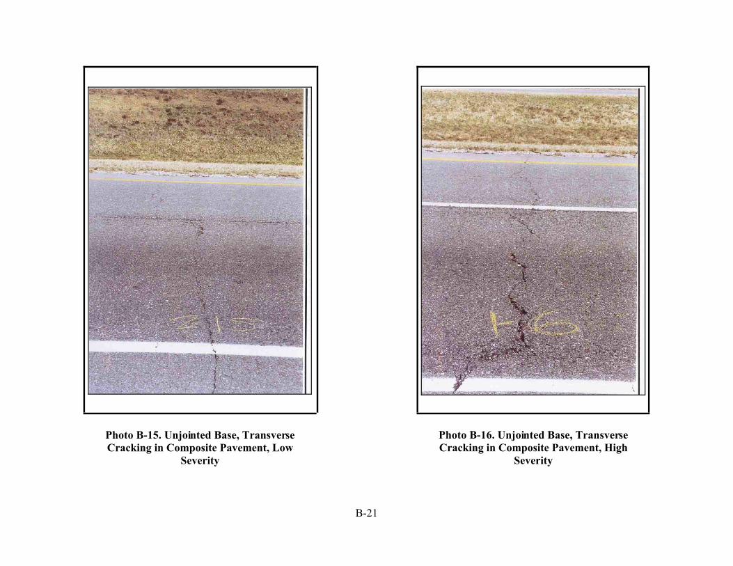
B-21
Photo B-15. Unjointed Base, TransverseCracking in Composite Pavement, Low
Severity
Photo B-16. Unjointed Base, TransverseCracking in Composite Pavement, High
Severity
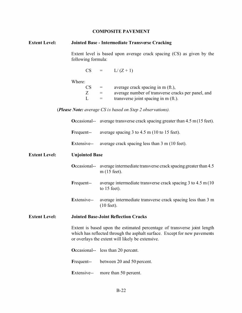
B-22
COMPOSITE PAVEMENT
Extent Level: Jointed Base - Intermediate Transverse Cracking
Extent level is based upon average crack spacing (CS) as given by thefollowing formula:
CS = L/ (Z + 1)
Where:CS = average crack spacing in m (ft.),Z = average number of transverse cracks per panel, andL = transverse joint spacing in m (ft.).
(Please Note: average CS is based on Step 2 observations).
Occasional-- average transverse crack spacing greater than 4.5 m (15 feet).
Frequent-- average spacing 3 to 4.5 m (10 to 15 feet).
Extensive-- average crack spacing less than 3 m (10 feet).
Extent Level: Unjointed Base
Occasional-- average intermediate transverse crack spacing greater than 4.5m (15 feet).
Frequent-- average intermediate transverse crack spacing 3 to 4.5 m (10to 15 feet).
Extensive-- average intermediate transverse crack spacing less than 3 m(10 feet).
Extent Level: Jointed Base-Joint Reflection Cracks
Extent is based upon the estimated percentage of transverse joint lengthwhich has reflected through the asphalt surface. Except for new pavementsor overlays the extent will likely be extensive.
Occasional-- less than 20 percent.
Frequent-- between 20 and 50 percent.
Extensive-- more than 50 percent.

B-23
Photo B- 17. Jointed Base, Reflection Cracking in CompositePavement, Medium Severity
Photo B- 18. Jointed Base, Reflection Cracking in CompositePavement, High Severity

B-24
COMPOSITE PAVEMENT
Distress Type: Longitudinal Cracking
Description: A crack or break approximately parallel to the pavement centerline.Longitudinal joints and pavement edges of underlying rigid base usuallyreflect through the asphalt surface as a result of thermal movement in theunderlying slab. Poor paving lane joint construction can also result in alongitudinal crack. All types of longitudinal cracking (random, centerline,edge, etc.) are included in this distress classification for compositepavements.
Note: Crack width is defined as the sum of all cracks if more than one ispresent at the location of measurement.
Low-- crack width less than 6 mm (1/4 inch) with no spalling ordistortion along crack edges.
Medium-- crack opened or spalled to a width between 6 mm and 25 mm(1/4 and 1 inch) over at least one half its length.
High-- crack opened or spalled to a width greater than 25 mm (1inch) over at least one half its length.
Extent Level: Based upon the average linear feet of longitudinal cracking per 30 m (perstation of 100 feet length).
Occasional-- less than 15 m/30 m (50 feet per station).
Frequent-- between 15 and 45 m/30 m (50 and 150 feet per station).
Extensive-- more than 45 m/30 m (150 feet per station). Completereflective longitudinal cracking along the pavement centerlineand edge [60 linear m/ 30 m (200 linear feet per station)] istermed extensive.

B-25
Photo B- 19. Longitudinal Cracking in Composite Pavement, High Severity

B-26
COMPOSITE PAVEMENT
Distress Type: Pressure Damage/Upheaval
Description: Upheaval is a bump or hump in the pavement surface at a transverse joint orcrack. The upheaval is a result of thermal expansion in the underlyingconcrete base creating compressive forces.
Severity Level: Low-- bump height less than 13 mm (½ inch), barely noticeableeffect upon ride.
Medium-- bump height 13 to 25 mm (½ to 1 inch) with a readilynoticeable effect upon ride quality.
High-- bump height greater than 25 mm (1 inch) severely reducingride quality.
Extent Level: Occasional-- upheaval is present along less than 20 percent of the joints.
Frequent-- upheaval occurs along 20 to 50 percent of the joints.
Extensive-- greater than 50 percent of the joints exhibit upheaval.

B-27
Photo B- 20. Pressure Damage/Upheaval in Composite Pavement,Medium Severity
B-28
COMPOSITE PAVEMENT
Distress Type: Crack Sealing Deficiency
Description: Crack sealing deficiency is crack sealing which is no longer effective inpreventing intrusion of water or cracks which have never been sealed.
Severity Level: Severity levels are not considered.
Extent Level: Extent is based upon the percentage of crack length in the pavement surfacewhich is not effectively sealed.
Occasional-- less than 20 percent of the cracks along the pavement sectionare not effectively sealed.
Frequent-- between 20 and 50 percent of the cracks along the pavementsection are not effectively sealed.
Extensive-- more than 50 percent of the cracks along the pavement sectionare not effectively sealed.

B-29
Photo B-21. Crack Sealing Deficiency, Unsealed Cracks
Photo B-22. Crack Sealing Deficiency, Cracks not sealed properly

C-1
APPENDIX C
Description of Distresses inJointed Reinforced Concrete or
Jointed Plain Concrete Pavements (JRC/JPC Pavements)

C-2
JRC/JPC PAVEMENT
Distress Type: Surface Deterioration
Description: Disintegration or loss of concrete from the surface of the pavement. Includesscaling and abrasion. Scaling is the flaking away of the concrete surface.Abrasion is similar to scaling in that a loss of fine, surface aggregate occurs.Abrasion is usually a result of weathering and traffic wear and is normallyconfined to the wheel track area.
Severity Level: Low-- Aggregate visible.
Medium-- Surface has an open texture and is moderately rough withconsiderable loss of fine aggregate and some coarse aggregateremoved.
High-- Surface rough or pitted.
Extent Level: Occasional-- Less than 20 percent of the surface area.
Frequent-- 20 to 50 percent of the surface area.
Extensive-- Equal to or greater than 50 percent of the surface area. Thislevel includes continuous distress in both wheel tracks.
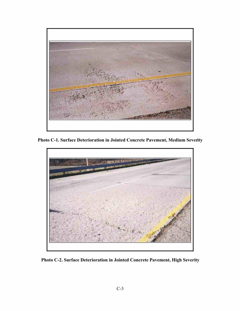
C-3
Photo C-1. Surface Deterioration in Jointed Concrete Pavement, Medium Severity
Photo C-2. Surface Deterioration in Jointed Concrete Pavement, High Severity
C-4
JRC/JPC PAVEMENT
Distress Type: Popouts
Description: Cone shaped holes in the pavement surface with aggregates at the bottom andunrelated to joint or crack spalling. Aggregate quality is related to this typeof distress. Popouts usually range from 25 to 100 mm (1 to 4 inches) indiameter and from 13 to 50 mm (½ to 2 inches) in depth.
Severity Level: Severity levels are not considered.
Extent Level: Occasional-- Less than 20 percent of the area is affected.
Frequent-- 20 to 50 percent of the area is affected.
Extensive-- More than 50 percent of the area is affected.

C-5
Photo C-3. Popout in a Concrete Pavement, Plan and Cross-sectional Views
Photo C-4. Popouts in a Jointed Concrete Pavement

C-6
JRC/JPC PAVEMENT
Distress Type: Patching
Description: Patching is either the placing of additional material on the surface of theexisting pavement or the replacement of existing pavement in isolated areas.
Deductions shall be made for all patches present in the pavement which aremade with asphalt concrete material and are the result of deterioration and/ormaintenance since the last construction project.
No deductions shall be made for existing patches which consist of soundconcrete. Where deterioration exists with a concrete repair, the deteriorationshall be rated as part of the pavement.
Multiple patches found along a transverse joint or crack which do notinterconnect shall be added together to represent the size of one patch.
Multiple patches found along a longitudinal joint or crack which do notinterconnect, but are within the same slab, shall be added together torepresent the size of one patch.
Severity Level: Low-- Patch size <0.1 m2 (1 sq. ft.), and patches are not deteriorated.
Medium-- Patch size < 0.1 m2 (1 sq. ft.), with deterioration present.
High-- Patch size > 0.1 m2 (1 sq. ft.), regardless of deterioration.
Extent Level: Occasional-- <10 patches/1.6 km (per mile).
Frequent-- 10 to 20 patches/1.6 km (per mile).
Extensive-- >20 patches/1.6 km (per mile).

C-7
Photo C-5. Patching in Jointed Concrete Pavement, Low Severity
Photo C-6. Patching in Jointed Concrete Pavement, High Severity

C-8
JRC/JPC PAVEMENT
Distress Type: Pumping
Description: Pumping is the ejection of fine soil particles through pavement cracks, joints,or along pavement edges. Pumping can be identified by the presence ofsurface staining and base or subgrade material near joints or cracks. Shoulderdisintegration at the pavement edge is often an indicator of pumping beneaththe slab.
Severity Level: Severity is based upon the rater's degree of certainty that pumping isoccurring as indicated by visual evidence.
L & M-- Some staining of the surface around cracks or joints is noted.Rater is quite certain that pumping exists.
High-- Clear evidence that pumping exists. Excessive staining,medium severity or greater, faulting, corner breaks orpunchouts. Rater is quite certain that pumping exists.
Extent Level: Occasional-- Less than 10 of the joints and cracks exhibit pumping.
Frequent-- 10 to 25 percent of the joints and cracks exhibit pumping.
Extensive-- More than 25 percent of the joints and cracks exhibitpumping.

C-9
Photo C-7. Pumping in Jointed Concrete Pavement, High Severity
Photo C-8. Pumping in Jointed Concrete Pavement, Low Severity

C-10
JRC/JPC PAVEMENT
Distress Type: Faulting
Description: Faulting is the difference in elevation between abutting slabs at transversejoints or cracks. Faulting is usually caused by a pumping action ofunderlying fine grained materials, settlement of soft subgrade, or from curlingor warping of slabs due to temperature and moisture gradients.
Note: If transverse cracks are faulted, write the letter "C" on the ratingform. If both cracks and joints are faulted, write the letter "B".Otherwise, faulting indicates only joints.
Severity Level: Low-- Less than 6 mm (1/4 inch) fault.
Medium— 6 mm to 13 mm (1/4 to ½ inch) fault.
High-- Greater than 13 mm (½ inch) fault.
Extent Level: Occasional-- Faulting occurs along less than 20 percent of the joints andcracks.
Frequent-- Faulting occurs along 20 to 50 percent of the joints andcracks.
Extensive-- More than 50 percent of the joints and cracks are faulted.

C-11
Photo C-9. Sketch showing Faulting in Jointed Concrete Pavement
Photo C-10. Faulting in Jointed Concrete Pavement

C-12
JRC/JPC PAVEMENT
Distress Type: Settlement
Description: Settlement is a dip or depression in the longitudinal profile of the pavementsurface. Settlement should be considered a distress when it causes anoticeable effect upon riding quality.
Severity Level: Severity is based upon the effect of the settlement or waves upon ride qualityand vehicle control when traveling along the roadway at 60 km/hour (40MPH, step 1 of the monitoring procedure).
Low-- Noticeable effect upon ride, driver able to maintain vehiclecontrol easily.
Medium-- Some discomfort to passengers, driver able to maintaincontrol with slight corrective action.
High-- Definite effect upon ride quality. Noticeable profile dips insettlement areas greater than 150 mm (6 inches). Wavescause rocking of vehicle similar to motion created atmoderately faulted jointed crack pavements.
Extent Level: Occasional-- Less than 2 settlement/1.6 km (per mile) of roadway.
Frequent-- 2 to 4 settlement areas/1.6 km (per mile) of roadway.
Extensive-- More than 4 settlements/1.6 km (per mile) of roadway.

C-13
Photo C-11. Settlements in Jointed Concrete Pavement, Medium Severity

C-14
JRC/JPC PAVEMENT
Distress Type: Transverse Joint Spalling
Description: Joint spalling is the break up or disintegration of the concrete at longitudinalor transverse pavement joints. A spall normally does not extend verticallythrough the slab but rather intersects the joint at an angle. Often jointspalling is the result of durability ("D") cracking of the pavement. The rateris asked to indicate on the rating form if the joint spalling is a result of "D"cracking. Durability ("D") cracking is a series of fine crescent-shaped cracksin the concrete surface which usually runs parallel to a joint or major crackand curve across slab corners. Cracking pattern is normally concave inrelation to slab corners or joints. D-cracking can eventually lead todisintegration and spalling of the concrete near the joints or corners of theslab.
Severity Level: Low-- Spalls less than 100 mm (4 inches) wide, measured to thecenter of the joint, with loss of material, or spalls with no lossof material and no patching.
Medium-- spalls 100 mm to 225 mm (4 to 9 inches) wide, measured tothe center of the joint, with loss of material.
High-- Spalls greater than 225 mm (9 inches) wide, measured to thecenter of the joint, with loss of material.
Extent Level: Occasional-- Less than 25 percent of the transverse joints are spalled.
Frequent-- 25 to 75 percent of the transverse joints are spalled.
Extensive-- More than 75 percent of the transverse joints are spalled.

C-15
Photo C-12. Transverse Joint Spalling in Jointed Concrete Pavement, Low Severity
Photo C-13. Transverse Joint Spalling in Jointed Concrete Pavement, High Severity

C-16
JRC/JPC PAVEMENT
Distress Type: Joint Sealant Damage
Description: Joint sealant damage is any deterioration of the sealant which permits wateror incompressibles to enter the joint. Damage includes disintegration,removal, pull out, hardening or debonding of the joint material from theadjoining slab edge.
Severity Level: Severity levels are not considered for this distress.
Extent Level: Occasional-- Less than 20 percent of the joints are not effectively sealed.
Frequent-- 20 and 50 percent of the joints are not effectively sealed.
Extensive-- Greater than 50 percent of the joints are not effectively sealed.

C-17
Photo C-14. Joint Sealant Damage in Jointed Concrete Pavement
Photo C-15. Joint Sealant Damage in Jointed Concrete Pavement

C-18
JRC/JPC PAVEMENT
Distress Type: Pressure Damage
Description: Pressure damage may be spalling, crushing, or upheaval at transverse jointsor cracks resulting from expansion of the concrete layer. Pressure inducedspalling is differentiated from other joint spalling by the shape of the spalledarea. Pressure spalls are usually 150 to 300 mm (6 to 12 inches) longmeasured from the crack or joint and up to 300 mm (12 inches) wide.
Severity Level: Separate severity levels for pressure damage spalling are not defined. Allpressure damage spalling is considered severe since this distress may be apredictor or more serious pressure distress (blow ups).
Extent Level: Extent is based upon the number of transverse joints which exhibit pressuredamage spalling.
Occasional-- Less than 1/1.6 km (per mile).
Frequent-- Between 1 and 3/1.6 km (per mile).
Extensive-- More than 3/1.6 km (per mile).

C-19
Photo C-16. Pressure Damage in Jointed Concrete Pavement
Photo C-17. Pressure Damage in Jointed Concrete Pavement

C-20
JRC/JPC PAVEMENT
Distress Type: Transverse Cracking
Description: A crack or break at approximately right angles to the pavement centerline.Some transverse cracks (hairline shrinkage cracks) are expected in reinforcedconcrete pavements which have large transverse joint spacing. Additionaltransverse cracking could be caused by repeated heavy traffic loading,thermal and moisture gradients and subgrade settlement or consolidation.
Severity Level: Low-- Hairline or tight with little crack spalling.
Medium-- Crack opened or spalled at the surface to a width of 6 mm to25 mm (1/4 inch to 1 inch) over a distance equal to at leastone-half the crack length.
High-- Crack opened or spalled at the surface to a width greater than25 mm (1 inch) over a distance equal to at least one-half thecrack length.
Extent Level: Extent level is based upon average crack spacing (CS) between intermediatetransverse cracks as given by the following expression:
CS = L / ( Z + 1 )
where:CS = average crack spacing, m (ft),Z = average number of transverse cracks per panel, andL = transverse joint spacing, m (ft).
Average CS is based upon step 2 observations.
Occasional-- CS > 4.5 m (15 ft).
Frequent-- 3 m (10 ft) < CS < 4.5 m (15 ft).
Extensive-- CS < 3 m (10 ft).

C-21
Photo C-18. Transverse Cracking in Jointed Concrete Pavement, Low Severity
Photo C-19. Transverse Cracking in Jointed Concrete Pavement, High Severity

C-22
JRC/JPC PAVEMENT
Distress Type: Longitudinal Cracking
Description: A crack or break approximately parallel to the pavement centerline. Thistype of cracking is usually associated with subgrade settlement or insufficientbearing support.
Severity Level: Low-- Hairline or tight cracks with little crack spalling.
Medium-- Crack opened or spall at the surface to a width of 6 mm to 25mm (1/4 inch to 1 inch) over a distance equal to at least one-half the crack length.
High-- Crack opened or spalled at the surface to a width greater than25 mm (1 inch) over a distance equal to at least one-half thecrack length.
Extent Level: Occasional-- Less than 5 percent of the slabs have longitudinal cracking.
Frequent-- Between 5 and 20 percent of the slabs have longitudinalcracking.
Extensive-- More than 20 percent of the slabs have longitudinal cracking.

C-23
Photo C-20. Longitudinal Cracking in Jointed Concrete Pavement, Medium Severity
Photo C-21. Longitudinal Cracking in Jointed Concrete Pavement, Medium Severity

C-25
JRC/JPC PAVEMENT
Distress Type: Corner Breaks
Description: A corner break is a crack that intersects transverse joints or cracks and alongitudinal edge diagonally. The leg size of the triangular break is usuallygreater than 300 mm (12 inches). Corner breaks can be differentiated fromspalling by: (1) corner breaks extend vertically through the entire slabwhereas spalls are only partial depth cracks, and (2) the triangle formed bya corner break is usually much larger than that of a spall.
Severity Level: Low-- Crack width less than 6 mm (1/4 inch) with no spalling orsettlement of the broken area.
Medium-- Crack width between 6 mm to 25 mm (1/4 inch to 1 inch)with some spalling and minor settlement of the broken area.
High-- Crack width greater than 25 mm (1 inch) and/or muchspalling and settlement of the broken area. High severity mayalso be identified by shattering of the broken area byformation of smaller pieces within the corner break area.
Extent Level: Occasional-- Less than 4 corner breaks/1.6 km (per mile).
Frequent-- 4 and 10 corner breaks/1.6 km (per mile).
Extensive-- More than 10 corner breaks/1.6 km (per mile).

C-26
Photo C-22. Corner Break in Jointed Concrete Pavement, Medium Severity
Photo C-23. Corner Breaks in Jointed Concrete Pavement, High Severity

D-1
APPENDIX D
Description of Distresses in Continuously Reinforced Concrete Pavements (CRCP)

D-2
CRC PAVEMENT
Distress Type: Surface Deterioration
Description: Disintegration or loss of concrete from the surface of the pavement. Includesscaling and abrasion. Scaling is the flaking away of the concrete surface.Abrasion is similar to scaling in that a loss of fine, surface aggregate occurs.Abrasion is usually a result of weathering and traffic wear and is normallyconfined to the wheel track area.
Severity Level: Low-- Aggregate visible.
Medium-- Surface has an open texture and is moderately rough withconsiderable loss of fine aggregate and some coarse aggregateremoved.
High-- Surface rough or pitted.
Extent Level: Occasional-- Less than 20 percent of the surface area.
Frequent-- 20 to 50 percent of the surface area.
Extensive-- Equal to or greater than 50 percent of the surface area. Thislevel includes continuous distress in both wheel tracks.

D-3
Photo D-1. Surface Deterioration in CRC Pavement, Medium Severity
Photo D-2. Surface Deterioration in CRC Pavement, High Severity

D-4
CRC PAVEMENT
Distress Type: Popouts
Description: Cone shaped holes in the pavement surface with aggregates at the bottom andunrelated to joint or crack spalling. Aggregate quality is related to this typeof distress. Popouts usually range from 25 to 100 mm (1 to 4 inches) indiameter and from 13 to 50 mm (½ to 2 inches) in depth.
Severity Level: Severity levels are not considered.
Extent Level: Occasional-- Less than 20 percent of the area is affected.
Frequent-- 20 to 50 percent of the area is affected.
Extensive-- More than 50 percent of the area is affected.

D-5
Photo D-3. Popout in CRC Pavement, Plan and Cross-section Views
Photo D-4. Popouts in CRC Pavement

D-6
CRC PAVEMENT
Distress Type: Patching
Description: Patching is either the placing of additional material on the surface of theexisting pavement or the replacement of existing pavement in isolated areas.
Deductions shall be made for all patches present in the pavement which aremade with asphalt concrete material and are the result of deterioration and/ormaintenance since the last construction project.
No deductions shall be made for existing patches which consist of soundconcrete. Where deterioration exists with a concrete repair, the deteriorationshall be rated as part of the pavement.
Multiple patches found along a transverse joint or crack which do notinterconnect shall be added together to represent the size of one patch.
Multiple patches found along a longitudinal joint or crack which do notinterconnect, but are within the same slab, shall be added together torepresent the size of one patch.
Severity Level: Low-- Patch size <0.1 m2 (1 sq. ft.), and patches are not deteriorated.
Medium-- Patch size <0.1 m2 (1 sq. ft.)., with deterioration present.
High-- Patch size >0.1 m2 (1 sq. ft.), regardless of deterioration.
Extent Level: Occasional-- <10 patches/1.6 km (per mile).
Frequent-- 10 to 20 patches/1.6 km (per mile).
Extensive-- >20 patches/1.6 km (per mile).
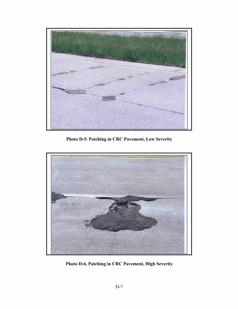
D-7
Photo D-5. Patching in CRC Pavement, Low Severity
Photo D-6. Patching in CRC Pavement, High Severity

D-8
CRC PAVEMENT
Distress Type: Pumping
Description: Pumping is the ejection of fine soil particles through pavement cracks, joints,or along pavement edges. Pumping can be identified by the presence ofsurface staining and base or subgrade material near joints or cracks. Shoulderdisintegration at the pavement edge is often an indicator of pumping beneaththe slab.
Severity Level: Severity is based upon the rater's degree of certainty that pumping isoccurring as indicated by visual evidence.
L & M-- Some staining of the surface around cracks or joints is noted.Rater is quite certain that pumping exists.
High-- Clear evidence that pumping exists. Excessive staining,medium severity or greater, faulting, corner breaks orpunchouts. Rater is quite certain that pumping exists.
Extent Level: Occasional-- Less than 10% of the joints and cracks exhibit pumping.
Frequent-- 10 to 25% of the joints and cracks exhibit pumping.
Extensive-- More than 25% of the joints and cracks exhibit pumping.

D-9
Photo D-7. Pumping in CRC Pavement, Medium Severity
Photo D-8. Pumping, High Severity

D-10
CRC PAVEMENT
Distress Type: Settlement and Waves
Description: Because CRC pavements have short transverse crack spacing, thesepavements can develop short waves or undulation as a result of poor supportconditions, frost heave, or permanent deformation of the subgrade.Settlement is a dip or depression in the longitudinal profile of the pavementsurface.
Severity Level: Severity is based upon the effect of the settlement or waves upon ride qualityand vehicle control when traveling along the roadway at 60 km/hour (40MPH, (step 1 of the monitoring procedure).
Low-- Noticeable effect upon ride, driver able to maintain vehiclecontrol easily.
Medium-- Some discomfort to passengers, driver able to maintaincontrol with slight corrective action.
High-- Definite effect upon ride quality. Noticeable profile dips insettlement areas greater than 150 mm (6 inches). Wavescause rocking of vehicle similar to motion created atmoderately faulted jointed crack pavements.
Extent Level: Occasional-- Less than 2 settlements/1.6 km (per mile) of roadway and/orwave along less than 20 percent of the section length.
Frequent-- 2 to 4 settlement areas/1.6 km (per mile) of roadway and/orwaves along 20 to 50 percent of the section length.
Extensive-- more than 4 settlement areas/1.6 km (per mile) of roadwayand/or waves along more than 50 percent of the sectionlength.

D-11
Photo D-9. Settlement in CRC Pavement

D-12
CRC PAVEMENT
Distress Type: Transverse Crack Spacing
Description: A crack at approximately right angles to the pavement centerline. Transversecracking in CRC pavements is normal. The cracking is detrimental if thespacing is less than or greater than that associated with good CRCperformance. Optimum CRC transverse crack spacing is about 1.5 m 2.4 m(5 to 8 feet).
Severity Level: Low-- Average crack spacing greater than 1 m (3 feet).
Medium-- Average crack spacing less than 1 m (3 feet), with fewintersecting cracks. Intersecting cracks are transverse crackswhich do not cross the entire pavement width but intersectother transverse cracks.
High-- Average crack spacing less than 1 m (3 feet), with manyintersecting cracks.
Extent Level: Extent is based upon the percentage of the section length having anundesirable transverse crack pattern.
Occasional-- Less than 20 percent.
Frequent-- 20 to 50 percent.
Extensive-- Greater than 50 percent.
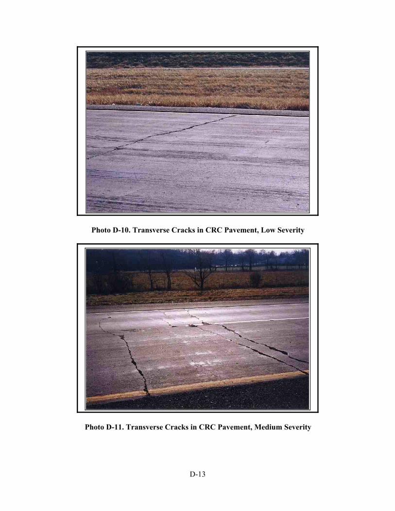
D-13
Photo D-10. Transverse Cracks in CRC Pavement, Low Severity
Photo D-11. Transverse Cracks in CRC Pavement, Medium Severity
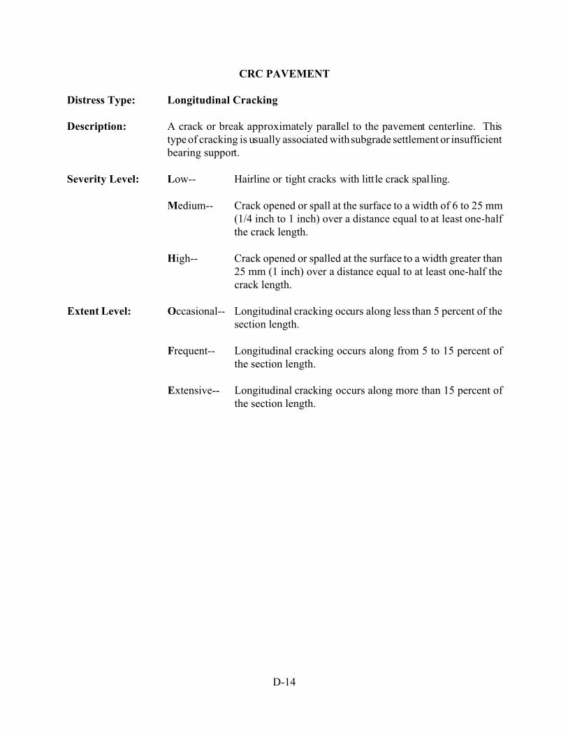
D-14
CRC PAVEMENT
Distress Type: Longitudinal Cracking
Description: A crack or break approximately parallel to the pavement centerline. Thistype of cracking is usually associated with subgrade settlement or insufficientbearing support.
Severity Level: Low-- Hairline or tight cracks with little crack spalling.
Medium-- Crack opened or spall at the surface to a width of 6 to 25 mm(1/4 inch to 1 inch) over a distance equal to at least one-halfthe crack length.
High-- Crack opened or spalled at the surface to a width greater than25 mm (1 inch) over a distance equal to at least one-half thecrack length.
Extent Level: Occasional-- Longitudinal cracking occurs along less than 5 percent of thesection length.
Frequent-- Longitudinal cracking occurs along from 5 to 15 percent ofthe section length.
Extensive-- Longitudinal cracking occurs along more than 15 percent ofthe section length.
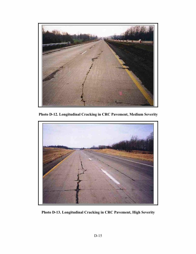
D-15
Photo D-12. Longitudinal Cracking in CRC Pavement, Medium Severity
Photo D-13. Longitudinal Cracking in CRC Pavement, High Severity

D-16
CRC PAVEMENT
Distress Type: Punchouts or Edge Breaks
Description: A punchout or edge break is a cracked rectangular area usually along theoutside pavement edge. A punchout requires formation of longitudinal crack(usually within the outer wheel track) which connects transverse cracks of theCRC pavement. The rectangular punchout area thus is defined by 2transverse cracks, the longitudinal crack and the outside pavement edge. Apunchout results from concrete that is over stressed because of shorttransverse crack spacing or poor support of the CRC pavement. Punchoutareas which have been repaired should be evaluated for patching distress.
Severity Level: This distress is rated only for Medium and High levels.
Medium-- Crack width greater than 6 mm (1/4 inch) with some spalling.Punchout area may be depressed up to 13 mm (½ inch).
High-- Punchout area is depressed more than 13 mm (½ inch) and/oris breaking up or shattering.
Extent Level: Occasional-- Fewer than 2 punchouts/1.6 m (per mile) of section length.
Frequent-- Between 2 and 5 punchouts/1.6 m (per mile) of section length.
Extensive-- More than 5 punchouts/1.6 m (per mile) of section length.
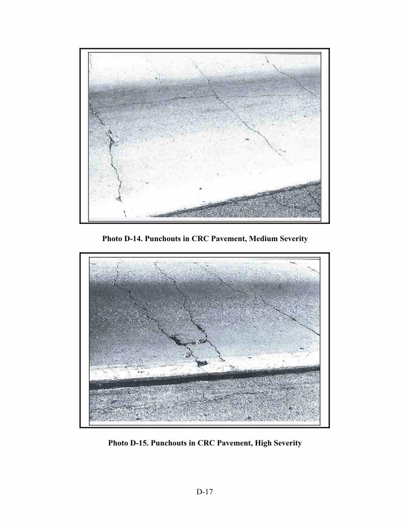
D-17
Photo D-14. Punchouts in CRC Pavement, Medium Severity
Photo D-15. Punchouts in CRC Pavement, High Severity

D-18
CRC PAVEMENT
Distress Type: Spalling
Description: Spalling in CRC pavements is the break up or disintegration of the concreteat transverse cracks. A spall normally does not extend vertically through theentire concrete layer but intersects the transverse crack at an angle. Thisdistress may be caused by the presence of high percentage of reinforcing steelin the pavement.
Severity Level: Low-- < 25 mm (1"), missing pieces.
Medium-- Distressed area 25 to 100 mm (1 - 4 inch) wide with most ofthe pieces missing.
High-- Distressed areas more than 100 mm (4 inch) wide with someor most of the pieces missing.
Extent Level: Extent of this distress is based upon the percentage of transverse crackswhich have spalled.
Occasional-- Less than 20 percent of the cracks.
Frequent-- Between 20 and 50 percent of the cracks.
Extensive-- More than 50 percent of the cracks.
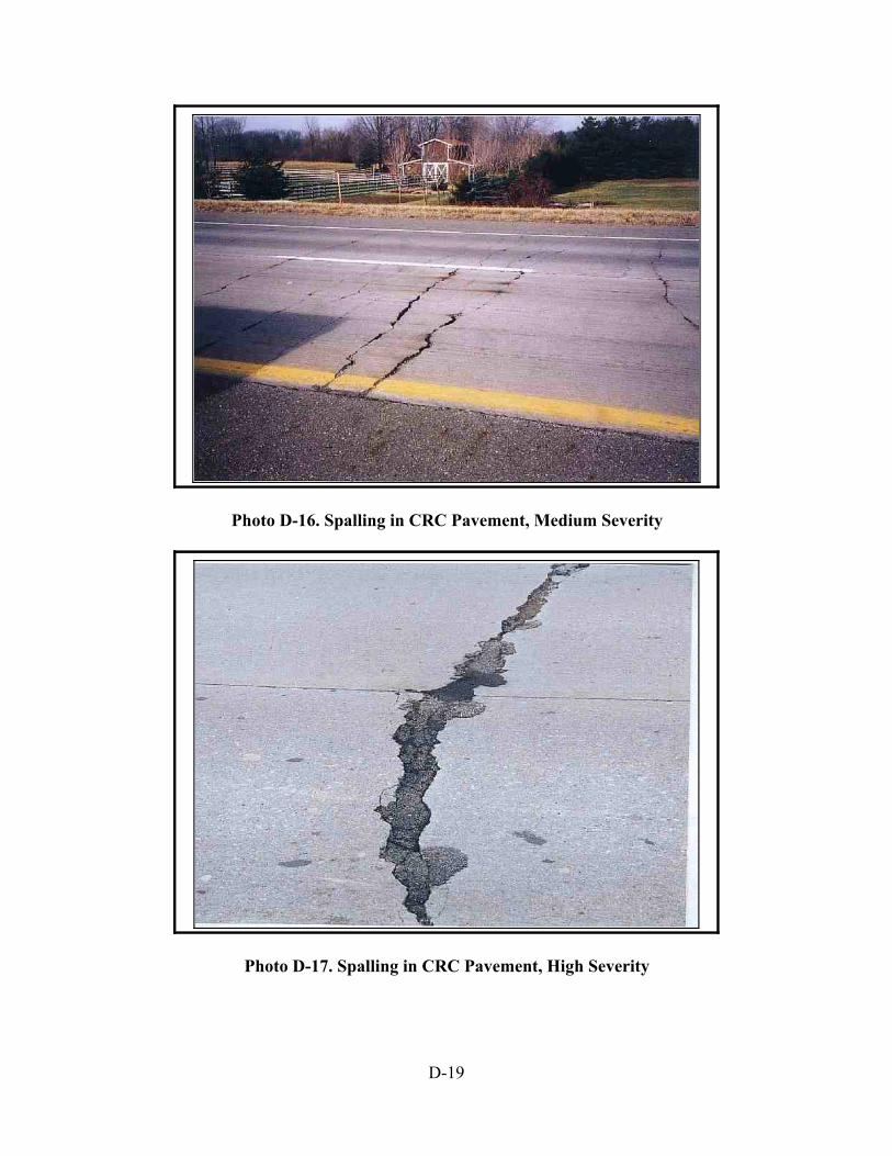
D-19
Photo D-16. Spalling in CRC Pavement, Medium Severity
Photo D-17. Spalling in CRC Pavement, High Severity
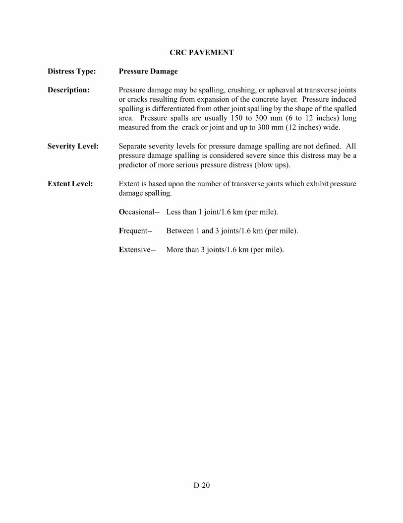
D-20
CRC PAVEMENT
Distress Type: Pressure Damage
Description: Pressure damage may be spalling, crushing, or upheaval at transverse jointsor cracks resulting from expansion of the concrete layer. Pressure inducedspalling is differentiated from other joint spalling by the shape of the spalledarea. Pressure spalls are usually 150 to 300 mm (6 to 12 inches) longmeasured from the crack or joint and up to 300 mm (12 inches) wide.
Severity Level: Separate severity levels for pressure damage spalling are not defined. Allpressure damage spalling is considered severe since this distress may be apredictor of more serious pressure distress (blow ups).
Extent Level: Extent is based upon the number of transverse joints which exhibit pressuredamage spalling.
Occasional-- Less than 1 joint/1.6 km (per mile).
Frequent-- Between 1 and 3 joints/1.6 km (per mile).
Extensive-- More than 3 joints/1.6 km (per mile).

D-21
Photo D-18. An Example of Pressure Damage in Jointed Concrete Pavement. PressureDamage in CRCP
is similar to as shown above.

E-1
APPENDIX E
Sources of Photographs used in Appendices A - D
E-2
Abbreviations Used in the Tables:
RII = Resource International, Inc.;
ODOT = Ohio Department of Transportation;
SHRP = SHRP-P-338 “Distress Identification manual for the Long-Term Pavement Performance Project”,Dated 1993;
Old Manual = ODOT’s previous PCR Manual, Dated February 1997.

E-3
Table E-1. List of Sources of Photographs of Appendix A and B
Photo # Source Photo # Source
A-1 RII B-1 RII
A-2 ODOT B-2 ODOT
A-3 Old Manual B-3 Old Manual
A-4 ODOT B-4 ODOT
A-5 Old Manual B-5 ODOT
A-6 ODOT B-6 ODOT
A-7 SHRP B-7 ODOT
A-8 ODOT B-8 ODOT
A-9 RII B-9 ODOT
A-10 ODOT B-10 RII
A-11 ODOT B-11 ODOT
A-12 RII B-12 ODOT
A-13 Old Manual B-13 RII
A-14 RII B-14 RII
A-15 Old Manual B-15 ODOT
A-16 RII B-16 ODOT
A-17 RII B-17 RII
A-18 ODOT B-18 ODOT
A-19 ODOT B-19 ODOT
A-20 RII B-20 ODOT
A-21 ODOT B-21 RII
A-22 RII B-22 ODOT
A-23 RII
A-24 Old Manual
Table E-2. List of Sources of Photographs Appendix C and D

E-4
Photo # Source Photo # Source
C-1 RII D-1 RII
C-2 RII D-2 SHRP
C-3 RII D-3 RII
C-4 RII D-4 RII
C-5 ODOT D-5 ODOT
C-6 ODOT D-6 ODOT
C-7 ODOT D-7 ODOT
C-8 ODOT D-8 ODOT
C-9 RII D-9 Old Manual
C-10 ODOT D-10 RII
C-11 RII D-11 RII
C-12 RII D-12 RII
C-13 RII D-13 RII
C-14 RII D-14 Old Manual
C-15 RII D-15 Old Manual
C-16 ODOT D-16 RII
C-17 ODOT D-17 ODOT
C-18 RII D-18 ODOT
C-19 ODOT
C-20 RII
C-21 RII
C-22 Old Manual
C-23 ODOT