Embed Size (px)
Citation preview

The Office of Highway Development Plats and Surveys Division
Plat Manual – 2020 Consultant Version
2
Office of Highway Development Plats and Surveys Division
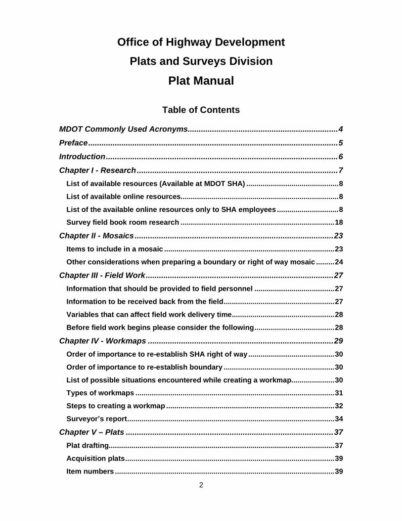
Plat Manual Table of Contents
MDOT Commonly Used Acronyms .................................................................... 4
Preface ................................................................................................................. 5
Introduction ......................................................................................................... 6
Chapter I - Research ........................................................................................... 7
List of available resources (Available at MDOT SHA) ............................................. 8
List of available online resources............................................................................. 8
List of the available online resources only to SHA employees .............................. 8
Survey field book room research ........................................................................... 18
Chapter II - Mosaics .......................................................................................... 23
Items to include in a mosaic ................................................................................... 23
Other considerations when preparing a boundary or right of way mosaic ......... 24
Chapter III - Field Work ..................................................................................... 27
Information that should be provided to field personnel ....................................... 27
Information to be received back from the field ...................................................... 27
Variables that can affect field work delivery time .................................................. 28
Before field work begins please consider the following ....................................... 28
Chapter IV - Workmaps .................................................................................... 29
Order of importance to re-establish SHA right of way .......................................... 30
Order of importance to re-establish boundary ...................................................... 30
List of possible situations encountered while creating a workmap ..................... 30
Types of workmaps ................................................................................................. 31
Steps to creating a workmap .................................................................................. 32
Surveyor’s report ..................................................................................................... 34
Chapter V – Plats .............................................................................................. 37
Plat drafting .............................................................................................................. 37
Acquisition plats ...................................................................................................... 39
Item numbers ........................................................................................................... 39

3
Conveyance plats .................................................................................................... 40
Road transfer plats .................................................................................................. 41
Donation plats .......................................................................................................... 43
Definition plats ......................................................................................................... 45
Plat finalization ........................................................................................................ 46
Chapter VI – Metes and Bounds Descriptions ................................................ 47
Parts of a metes and bounds description .............................................................. 49
Chapter VII - Review ......................................................................................... 51
Mosaic ...................................................................................................................... 51
Workmap .................................................................................................................. 52
Plat ............................................................................................................................ 52
Chapter VIII – GIS and Special Projects .......................................................... 53
Digital Assets Referencing System ........................................................................ 53
Appendix ........................................................................................................... 55
11x17 Plats and Plans…………….……………………...….…………...…................... 55
Deed Example (Exhibit 6).…………………………………..………………. ................. 55
Field/Survey Book (Exhibit 17)……………………………….…………….... ............... 55
Types of Easements Used by SHA…………………………………………................. 55
Plat Guidelines for Linework…………………………………………………. ............... 55
Plat Guidelines for Text Size……………………………………………….... ............... 55
Drafter’s Checklist………………………………………………….………….. ............... 55
Item Number Request Form……………………………………….…………. ............... 55
Donation Plat Requirements Checklist……………………………………… ............. 55
ORE Plat Transmittal Form…………………………………………….…….. ............... 55
Descriptions………………………………………………………….…………. ............... 55
Metes and Bounds Description Checklist...……………………….…….... ............... 55
Workmap Checklist……………………………………………………………. ............... 55
Workmap Submittal Form……………………………………….……………. ............... 55

4
MDOT Commonly Used Acronyms CAD or CADD – Computer Aided Design and Drafting
COMAR – Code of Maryland Regulations
DELM – Declaration of Extra Land Memo
DLR – Department of Licensing and Regulation
DNR – Department of Natural Resources
ERD – Engineering Resource Division (SHA OHD)
GIS – Geographic Information System
GPS – Global Positioning System
HDD – Highway Design Division (SHA OHD)
HHD – Highway Hydraulics Division (SHA OHD)
ICD – Innovative Contracting Division
MDOT SHA – Maryland Department of Transportation State Highway Administration
MOU – Memorandum of Understanding
NTP – Notice to Proceed
OBD – Office of Bridge Development (MDOT SHA)
OED – Office of Environmental Design (MDOT SHA)
OHD – Office of Highway Development (MDOT SHA)
OOS – Office of Structures (MDOT SHA)
OOTS – Office of Traffic and Safety (MDOT SHA)
OPPE – Office of Planning & Preliminary Engineering (MDOT SHA)
ORE – Office of Real Estate (MDOT SHA)
PLS – Professional Land Surveyor/Property Line Surveyor
PRD – Project Review Division (SHA OHD)
PSD – Plats and Surveys Division (SHA OHD)
R/W – Right of way
SRC – State Roads Commission
SUE – Subsurface Utility Engineering
TE – Transportation Engineer or Temporary Employee
TMDL – Total Maximum Daily Load
TSO – The Secretary’s Office (MDOT)
USGS – United States Geological Survey

5
Preface The purpose of this manual is to provide all Maryland Department of Transportation State Highway Administration (MDOT SHA) employees, consultants, and other personnel working for the State of Maryland guidelines, policies, and procedures established by the Plats and Surveys Division (PSD) to perform work for the state.
The Plats and Surveys Division creates plats to acquire lands either in fee simple or as an easement at the request of other divisions of the Office of Highway Development (OHD) in addition to other offices, e.g. Office of Structures (OOS), Office of Real Estate (ORE), and Office of Environmental Design (OED). The Plats and Surveys Division also produces plats, frequently accompanied by written descriptions, either to convey extra land or to transfer roads to other government agencies. These products are produced under the direct supervision of Professional Land Surveyors. They each lead a team of Transportation Engineers charged with the production of these plats and descriptions. These products are then signed and sealed by one of the Professional Land Surveyors.

6
Introduction The Plats and Surveys Division’s primary function involves identifying topographic features and property boundaries that can influence the design and costs of projects as well as property impacts that are developed and shown on SHA right of way plats. As the custodian of field survey information, PSD maintains an up-to-date inventory of existing survey data, provided by both in-house and consultant surveyors.
The Plats Section investigates and re-establishes existing base lines of right of way, right of way limits, easement locations, and existing boundary lines of adjacent land parcels impacted by roadway improvements. This effort utilizes public and private plats, deeds, and other documents as well as field monumentation to determine these outlines. This section computes new right of way acquisitions and prepares both the plats and the metes and bounds descriptions for those acquisitions. They also prepare plat descriptions for conveyances, road transfers, and condemnations. PSD supports many clients, such as the seven divisions of the Office of Highway Development (OHD), Office of Structures (OOS), the seven District Right of Way and Maintenance Offices, Office of Real Estate (ORE), Maryland Transportation Authority, the Office of Attorney General, and private consultants.
Plat work is supported by the field survey unit, the research and technical support center, the CADD mapping and control section, the topographic mapping team, and the geodetic control section.

7
Chapter I - Research Research is the systematic investigation into the project area to compile all information available pertaining to the project location. In addition, research is the first step when starting a new project. This serves as an introduction to the area and shows what previous work has been done on site and close by. The purpose of the research is to gather useful information that can be used to reset the base line and right of way as it exists today.
Next is a step-by-step list to follow when performing private land research:
1. From one of the following online sources, print a copy of the tax map from MERLIN, MDPGIS, or eGIS/DARS site showing the subject property (or properties) and the surrounding properties.
2. From one of the web sites listed above, print or save the SDAT sheets for each property.
3. Use MDLANDREC to print or save the title deeds of each property. For the subject property, search the title back until the description for that property comes out of a larger parcel.
4. Use PLATS.net to print or save the record plats referenced in the title deeds. Obtain the deed that the plat was created from (known as the underlying deed).
5. If an SDAT sheet either does not list a deed reference or has a wrong deed reference, use the Grantor or the Grantee to search for the deed in MDLANDREC.
a. Most counties allow searching of an individual or corporate name back to the 1970’s. Active indices are used beyond that. When opening a search window, the indices are arranged by the Grantor or the Grantee and date range. Each county may have a different way of indexing, and the older indexing can be a bit confusing. Read the guidelines found on the webpage on how to search in the older indices.
6. Other useful sites include the local historical societies, Maryland State Archives, the National Archives, and the Library of Congress to mention a few.
There are several private surveyors in the Baltimore area that have gathered records of other retired surveyors and/or surveying businesses and those records are available either at no cost or for a fee depending on the individual.

8
List of available resources (Available at MDOT SHA) Microfilms (Exhibit 1 and Exhibit 2) Microfiche files (Exhibit 3 and Exhibit 4) Construction and as-built plan sheets (Exhibit 5) Deeds (Exhibit 6) Yellow cards (Exhibit 7 and Exhibit 8) Road life cards Early history files (Exhibit 9) Agreements regarding right of way (Exhibit 10) Road transfers (Exhibit 11) Route folders (Exhibit 12 and Exhibit 13) Master plats (Exhibit 14 and Exhibit 15) Control maps (Exhibit 16) Survey field Books (Exhibit 17)
List of available online resources
MDLANDREC.NET (https://mdlandrec.net/main/index.cfm) – Needs login information.
MERLIN-Maryland’s Environmental Resource & Land Information Network (https://gisapps.dnr.state.md.us/MERLIN/index.html) – Does not need to have account.
SDAT – State Department of Assessment and Taxation. (http://sdat.dat.maryland.gov/RealProperty/Pages/default.aspx) Does not need to have account.
PLATS.NET (http://plato.mdarchives.state.md.us/pages/index.aspx) - Does not need to have account.
List of the available online resources only to SHA employees OREMS - Office of Real Estate Management System; ORE R/W Plat Search – Plats can be searched by a plat number, contract, route
#, county, etc. eGIS – This is a SHA wide tool with lots of information based on GIS format.
This tool is used to search for a variety of documents from a wide range of offices.
DARS (Digital Assets Referencing System) – a more in-depth explanation of this tool and some future additions is provided in Chapter VIII – GIS and Special Projects.

9
Exhibit 1 – Microfilms are used for item files and some early deeds.
Exhibit 2 - Microfilm boxes arranged by number (Found on the 2nd floor of ORE)

10
Exhibit 3 - Microfiche item files contain all the available correspondence relating to the acquisition or other matters under that item number. (Found on the 2nd floor of ORE)
Exhibit 4 - Microfiche zoomed in to show detail

11
Exhibit 5 – Construction and as-built plan sheets can include helpful information on history of project, e.g. field books and plat numbers.
(Found on eGIS or follow the link shahqfs3:\SHA\OHD\OHD-Archives) (11x17 printout can be found in Appendix A1.)

12
Exhibit 6 - Plats have secretary’s numbers, which indicate the deed used for acquisition of right of way. Example of secretary number, item number and deed reference:
Sec # 65513
Item # 76615
Liber 4876/390
(https://mdlandrec.net/main/index.cfm) See Appendix B.
Exhibit 7 – Yellow cards show the county, route number, project number, item number, person or entity form whom acquired and location in Master Plat files. (Found on the 2nd floor of ORE)

13
Exhibit 8 - Yellow card zoomed in to show detail
Exhibit 9 - Early history files include some road life cards and usually have a drawing showing the termini and the various contracts within the termini. (Found on the 2nd floor
of ORE)

14
Exhibit 10 - Agreements regarding right of way (Found on the 2nd floor of ORE)
Exhibit 11 - Road transfer agreements (RTA) with a county, municipality, or other government agency. (Found on the 2nd floor of ORE)

15
Exhibit 12 – A route folder contains previous research reports, research requests, and maps for the route in question. (Found on the 2nd floor of ORE)
Exhibit 13 - Inside look at route folder. (Found on the 2nd floor of ORE)
16
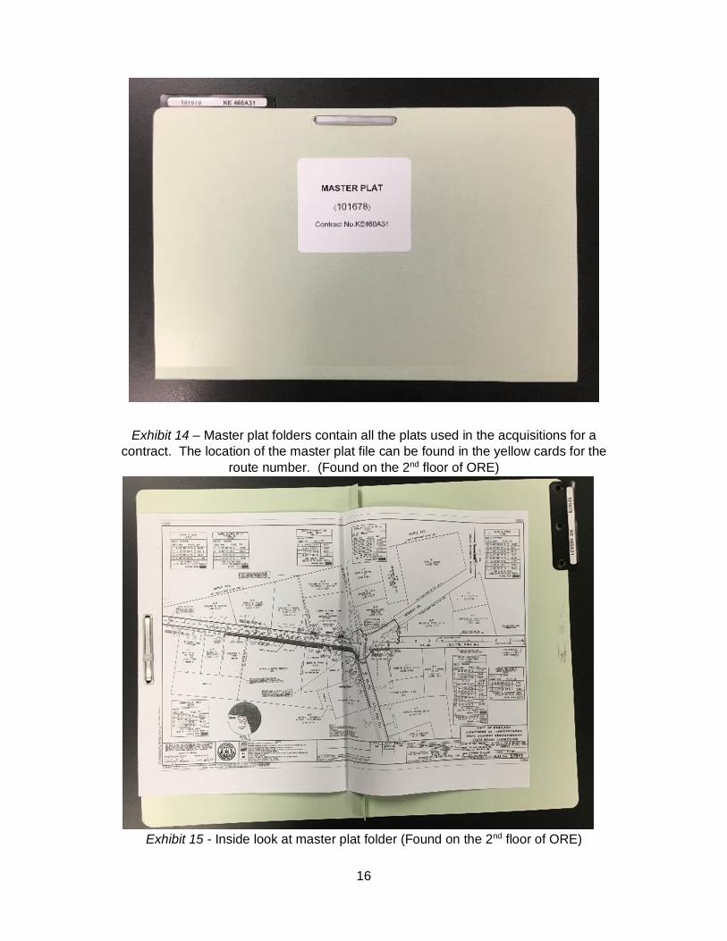
Exhibit 14 – Master plat folders contain all the plats used in the acquisitions for a contract. The location of the master plat file can be found in the yellow cards for the
route number. (Found on the 2nd floor of ORE)
Exhibit 15 - Inside look at master plat folder (Found on the 2nd floor of ORE)

17
Exhibit 16 – Control maps show an entire county or city with all state and federal routes and corresponding contract numbers. (Found on the 2nd floor of ORE)
Exhibit 17 – Survey field books have important information like property corners, old traverse, established base line information, right of way monuments, etc.
(See Appendix C for a full-size version of this page.)

18
Survey field book room research An additional resource to incorporate into the mosaic is field book research; this helps to recover as much information as needed to help to re-establish the base lines and right of way (Exhibit 18 and Exhibit 19). Book references can be found on plats, road plans (Exhibit 20 and Exhibit 21), construction plats, route work cards, old survey book indices (Exhibit 22, Exhibit 23, Exhibit 24, and Exhibit 25), or online using the Microsoft Access database (Exhibit 26).
Exhibit 18 – Survey field book cover

19
Exhibit 19 - Inside of survey field book showing a detailed drawing a bridge structure being used for re-establishing the base line
Exhibit 20 - Design plan title sheets show field books related to the project. (Found on eGIS or follow the link shahqfs3:\SHA\OHD\OHD-Archives)
(11x17 printout can be found in Appendix A2.)

20
Exhibit 21 - Zoomed in survey field book list on title sheet
Exhibit 22 - Survey field book index cover

21
Exhibit 23 - Inside of a survey field book index
Exhibit 24 - Inside of survey field book index

22
Exhibit 25 - Survey field book indices are organized by county
Exhibit 26 – Microsoft Access survey field book search

23
Chapter II - Mosaics A mosaic reflects the information found during research in a visual format. It is where the puzzle pieces are made and analyzed to see how they initially fit together and gives an overview of what needs to be searched for in the field. A good mosaic is an inclusive sketch of what the title and adjoining property lines look like along with title and monumentation calls.
Items to include in a mosaic A base line – found on SHA plats; Existing right of way (ROW) and easements – found on SHA plats (See Appendix
D for an explanation on the types of easements); Show all easements of record – found on recorded plats and in deeds; Parcels drawn by description or a subdivision plat – found using some of the
tools mentioned above; Information on the property corners and whether they have been found, set, or
monumented; A north arrow and a scale; All property calls. This can include monuments, roads, adjoiners, and anything
else that helps locate the property line in the field; Source of the property information, e.g. liber and folio, record plat, SHA plat,
valuation map, survey field book, or an unrecorded plat; Current owner names and/or tax map and parcel data; Error of closure with bearing and distance; Place a title block that includes name of the mosaic’s creator, FMIS number,
date, and any relevant notes.
24
Other considerations when preparing a boundary or right of way mosaic
Show any references on the mosaics that are set for all cardinal points on the base line; also, label book and page number for each of the references.
Look for spur lines. Spur lines may be used to find evidence to help set the base line.
Send copies of the book with the field crew, so if they cannot find the monuments shown on the mosaic, they will have the hand pulls to help find the references.
If the base line predates 1970, the reference could be hub & tack, which may be hard to find since the hub could be rotted away.
If the base line predates 1970, traverses coming off the main base line may locate property evidence. This evidence will be much more accurate than right angle topography.
If there are bridges or small structures within the project area, send a copy of the plans out with the field crew with what needs to be located to help set the base line.
The hand pulls can help set the traverse/base line points if the references cannot be located.
If the mosaic needs to be made into several plots for easier handling for the field crews, use sensible match marks for each plot.
Point numbers for deed parcels, right of way lines, base lines, easements, and meets and bounds property monumentation should be within the point ranges specified by the ics file:
o 1-2999 for existing points o 3001-3999 for traverse points o 4001-4999 for existing monumentation o 5001-5999 for base line points o 6001-6999 for existing right of way points o 7001-7999 for existing easement points o 8001-8999 for proposed right of way points o 9001-9999 for proposed easement points
Note on plotting
When plotting the descriptions, there may be gross errors. This could be the result of a scrivener’s error, commonly called a typographic error. In this case, search the title back until the description corrects itself or until it comes out of a larger parcel. The error may have been there from the beginning and can be resolved when completing the boundary determination and/or by evaluating the calls of the adjoiners.
An example of a mosaic is shown below (Exhibit 27 and Exhibit 28).

25
Exhibit 27 - Mosaic example showing base line, right of way, easements, and parcels. Base line is shown in yellow, existing right of way is represented by the orange line, and
all deed parcels shown here are shown in different colors so they can easily be identified. A north arrow is to be included on mosaics, workmaps, and plats.

26
Exhibit 28 – Mosaic example zoomed in for detail. Deed lines have notes indicating the bearing and distance per deed or subdivision plat. Property corners have notes
indicating if there is a call and what type of monument (iron pipe, iron angle, iron pin, rebar and cap, concrete monument, etc.). Show survey field book and page number on
monuments called for.

27
Chapter III - Field Work A mosaic shows all that was found during research field work is necessary to create the workmap. Evidence found in the field is what allows the surveyor to translate the mosaic information into real world lines set on the ground. All metes and bounds survey requests go to the Survey Assistant Division Chief and Senior Area Engineer. Please refer to the PSD Field Procedures Manual for more detail into field work.
Information that should be provided to field personnel A complete mosaic of the area in CADD format as well as a PDF or print out. A PDF of the mosaic overlaid on aerial imagery. Copies of any plats, deeds, survey books, or other documented material used in
the creation of the mosaic, as requested by the Area Engineer A dump file containing coordinates for search points of possible monumentation. Instructions of what to look for and what evidence to gather based on research. Existing traverse information from MDOT-SHA in the area.
Information to be received back from the field A DGN file that contains all field located evidence. Evidence should be clearly
labeled with as much detail as possible, like condition of the evidence found if it is bent or damaged, property cap information, size of pipe, etc.
A point dump of coordinates for all field located evidence. Copies of the bookwork for the location of the evidence. Pictures of the evidence located.

28
Variables that can affect field work delivery time To enter the work area, property notification letters need to be sent out to all
property owners at least 30 days in advance of field survey efforts. Field searches can require multiple attempts to recover full data sets. The typical
search area for a call to a property marker is a 15’ radius. Multiple attempts may be made if adjoining evidence requires re-evaluation.
Field crews will encounter both the public and private property owners, often for projects they know very little about. Some property owners may be inquisitive, some hostile, and some simply curious.
Field survey timelines can be affected by weather, obstructions, vegetation, traffic, and availability of survey control points. Field data recovered takes considerable efforts to become field “collected” data for engineers to work with.
Before field work begins please consider the following Type of road and average daily traffic (ADT) Weather conditions (seasons that the surveys should be performed) Condition of the area to be surveyed, if it is open and Global Positioning System
Real Time Kinematic (GPS RTK) can be used, or if conventional survey is needed
Safety measures for crew, availability, and affordability Time for approval of the work request (if it is a consultant) Available funds for consultant firms

29
Chapter IV - Workmaps A workmap reflects all the research prepared on a mosaic and field effort done to establish property lines and base lines. It documents the Professional Licensed Surveyor’s determination of where the lines are in the real world. Plats, descriptions, and other record documents will be built from this workmap. It should clearly reflect what evidence was looked for, what evidence was found and held, and how the property lines were established. This process is called boundary determination.
In preparing a workmap, the surveyor makes decisions on which evidence to use to set the boundary. If evidence in the field has no signs of being disturbed and is found as described in a deed, there is a very good chance that the monument can help to set the boundary. On the other hand, if the monument has signs that it has been disturbed or is a different material to what is described on the deed, those monuments may not be used in the final determination.
A workmap, in contrast to a mosaic file, cannot have a step-by-step guide on how to create the document because it is going to depend mainly on the calls of individual property descriptions, existing roads and monuments, found evidence, and if they were called for in the description. For example, a description can call to a concrete monument in the northernmost point of the parcel, but a rebar and cap is found instead. Though not called for, the rebar and cap can still be used.

30
Order of importance to re-establish SHA right of way 1. Recover monumented base line station and/or offset references as shown in
SHA centerline survey books (e.g. rebar & caps, x-cuts, P.K. nails, SHA/RR spikes, iron pipes).
2. Recover monumented base line stations and/or swing-tie references along base line spurs as shown in SHA survey books.
3. Recover property corner evidence as shown in SHA metes and bounds books. (Use these property corners as references to the original base line.)
4. If a bridge is near the site, obtain the SHA bridge plans and locate referenced key points on the bridge structure. Use these points as references to the original base line. (e.g. center of bridge joints or piers where they cross the base line.)
5. Use old geographic features as shown in SHA survey books as references to the original base line (e.g. fire hydrant, house corners, gas valves, utility poles, and property corners are sometimes located in topo books)
6. Use the roadway surface and/or the construction plan detail to re-establish the original base line geometry.
Order of importance to re-establish boundary When plat engineers work with recovered boundary evidence, the materials and recorded information is weighed based on a doctrine of priorities. They are weighed from greatest to least in the following order:
1. Lines run in the field (established by the original surveyor) 2. Adjoiners 3. Natural monuments (trees, large stones, streams, etc.) 4. Artificial monuments (rebars and caps, concrete monuments, pipes, etc.) 5. Courses 6. Distances 7. Area (intended area of property) 8. Coordinates (state plane or other)
List of possible situations encountered while creating a workmap Property description calls for field evidence that is not found in the field. Property description calls for a state or county road that has undergone
geometric changes. Property description calls for a type of monument, but a different type is found in
its place, e.g., the description calls for a stone monument, but a pipe is found. Property description call found in the field but has been disturbed. Property monumentation found and called for in the description, but the distance
is different in the description. When a workmap is finished, there is a workmap submittal document that must
be filled and submitted to the GIS Team; they oversee adding the workmap to Digital Assets Referencing System (DARS).

31
Base line re-establishment without SHA plats
Receive determination from Records and Research. o Turnpike o Charter o Ordinance
Ordinances may have been established through a city or municipality. District 2 is known for setting right of way monuments very accurately. On the shore, concrete roadways were laid out, 9-foot or 15-foot width, and then
widened. The center of the concrete roadways the actual center of right of way and not the center of the whole paved width
Local jurisdictional anomalies abound Prescriptive width may need to be used, which is what SHA has maintained for
20 plus years, which may include ditches. Use common sense, roadway surfacing, and adjoiner geometry to establish a
base line where none exist
Types of workmaps There are two types of workmaps specified on the Survey Request Form that PSD produces as a deliverable to its clients: the right of way workmap and the boundary workmap.
Right of way workmap
A right of way workmap is requested to determine the land area the State of Maryland owns in a project area. This allows the designer to know if the project can be completed within the existing right of way or if acquisitions are needed. A right of way mosaic is usually recommended to be included on the request. It is the plat engineer’s responsibility to talk to the requester and discuss the limits for the workmap after the mosaic is finished. See Exhibit 29 for a right of way workmap example.

32
Exhibit 29 - Right of way workmap for MD 650 including a north arrow, bar scale, and surveyor's report
Boundary workmap
A boundary workmap is requested to plot the boundary or property lines present in the project area to help determine where impacts are. A boundary workmap is recommended when there are known impacts outside of the existing right of way. If the requester does not know if work is going to impact private property, a subsequent survey request should be made when more information is available. For an example of a boundary workmap, see Exhibit 30.
Steps to creating a workmap Open the 2D workmap file. The name is going to be something like mWM-
0001m000.dgn. Reference the mosaic file (mMO-E001m000.dgn) and the metes and bounds
file (mMB-E001m000.dgn) into the workmap file. Compare field evidence located to property corners shown on the mosaic to
verify differences in distances and angles between calls on deeds and subdivisions and found monuments in the field.
After selecting which monuments to hold for corner or line to position the descriptions from deeds and subdivisions, rotate the base lines, the rights of way, easements, and parcels based on the monuments held and redrawn. Note: Parcel lines that call to intersect the right of way should be intersected in

33
the workmap. There should be no duplicate lines and no duplicate point numbers (e.g. one on top of another, two numbers with the same coordinate) in the workmap. For example, if the monument found at Point 357 is being held but its field observed coordinate is not held, label the points accordingly. If Point 357 is an IP (iron pipe) found and held on the right of way line, Point 6027 may be the computed corner that is near Point 357. Label all intersection points on the established right of way line.
After all lines have been drawn, annotate all lines in the drawing: lines of division, existing right of way lines, limits of existing easement, base lines of right of way, road names, property information, etc.
Add the final information, such as a north arrow, a bar scale, project information, and, most importantly, a summation of the surveyor’s report. The surveyor’s report is going to summarize the process on how the surveyor determined the boundary lines, right of way lines, base lines of right of way, and which monuments were held.
Exhibit 30 - Boundary Workmap – Shown here are parcels affected or that might be affected, existing right of way lines, base line of right of way, traverse points, existing easement lines, monumentation found, north arrow indicating coordinate datum used,
and the surveyor’s report.

34
Surveyor’s report There are two options for the surveyor’s report: the ics format and the narrative format. The ics format lists off each monument one at a time detailing the monument type, where it was referenced, where it is supposed to be, where it was found, and any special notes about it. An example of the ics format can be seen in Exhibit 31 with Exhibit 32 providing an illustration of the dgn file. The narrative format lists out all the pertinent details regarding the survey and monumentation. A list of necessary information for the surveyor’s report narrative format can be found listed below.
Exhibit 31 – Ics format of the surveyor’s report detailing a monument found in the field
Exhibit 32 – Close-up of a workmap zoomed in to show a monument and its associated description

35
List of items which may be found in a surveyor’s report
Company/Surveyor’s Information o Company name o Company address o Company contact number o Company email address o Surveyor-in-responsible charge/position or title
Project Information o SHA FMIS No. o Company Project No. o Company Project Manager / Area Engineer / Team Leader o Client Information
Client Client’s address Client’s contact number Client’s email address
Purpose of the survey Project location/address Survey Information
o Date of the last day of field work on the project o Control
Horizontal datum Method used to determine datum/realization Control adjustment method/results Calibration/localization results and VRS service provider Type of coordinates (grid/ground) Project grid/ground combined scale factor Survey units
o Equipment Model and serial numbers of instrumentation Calibration certificates
o Personnel Field crew names/titles Office staff names/titles Certified QA/QC checklist Daily crew cards/log sheets
o Records examined (including but not limited to) SHA right of way plats County right of way plats Easement plats/descriptions Subdivision plats Condominium plats Deed descriptions Equity & will records Field book notes Grantor/grantee indices search Public survey records Private survey records Government survey records

36
Parole evidence Patent records Photographs Contacts/conversation logs pertinent to the survey
Property notification letters o Include sample letter o Names and addresses used for delivery
Surveyed parcel/lot Information o Tax map (with property highlighted) o SDAT sheet o Current title deed/description o Current plat (if applicable) o Clear chain of title (at least back to the parent tract) o List of encumbrances (servient/dominant estates of the subject property,
etc.) o List of right of way/easement plats o Deed/plat mosaic based on current title description and any prior
descriptions, as necessary o Describe any differences between current/prior descriptions (include
mathematical closures) o Narrative explaining in detail method used to establish/re-establish each
corner for the above parcel/lot. Include any noteworthy information that may be instrumental in re-establishing the same property corner in the future. Include differences between measured and record survey angle/distances.
o Without expressing a legal opinion as to the ownership or the nature of a potential encroachment, describe any perceived title issues uncovered while preparing the survey. This could include perceived gaps, overlaps, encroachments, etc.
Final survey data o Signed and sealed work map (boundary survey) o Signed and sealed metes and bounds description (if applicable) o Final ASCII (American Standard Code for Information Interchange)
coordinate list for all project points o Final area computations for each surveyed parcel o Certified final deliverable check list based on scope o Certificate satisfying COMAR (Code of Maryland Regulations) 09.13.06

37
Chapter V – Plats Plat definition: A diagram drawn to scale showing all essential data pertaining to the boundaries and subdivisions of a tract of land, as determined by survey or protraction. A plat should show all the data required for a complete accurate description of the land which it delineates, including the bearings (or azimuths) and lengths of the boundaries of each subdivision. A plat may constitute a legal description of the land and be used in lieu of a written description. (PAGE 196, DEFINITIONS OF SURVEYING AND ASSOCIATED TERMS)
Plat, right of way: A plan of a highway improvement showing the old and the new highways and the right of way (or interest in lands) to be acquired. (PAGE 196, DEFINITIONS OF SURVEYING AND ASSOCIATED TERMS)
Plat drafting To draft a plat, there are rules to follow. Some depend on the drafter’s preferences. For a DGN file, the color of every line has a meaning (Color numbers are based on Microstation V8 Select Series 2).
Yellow (4) – Right of way base line Orange (13) – Existing right of way lines to be relinquished Red (3) – Right of way (proposed) or to remain White (0) – Property lines Pink (12) – Temporary easement and proposed perpetual easement Light Blue (11) – Existing easement
The Plats and Surveys Division (PSD) has established drafting standards for all manner of plats, topographic drawings, and workmaps: line weight and style, text size and font,

38
language in notes and the placement of notes in relation to each line type, north arrow, and most other plat elements. These standards have been written in a “Plat Guidelines” document, which is attached as Appendix E for linework and Appendix F for text size. Within MicroStation, under the heading Menus, there is a Plats and Surveys Plat Workmap Model (mPL) that, when opened, creates a selectable list of each line type for easements, right of way, property, etc. Also, by utilizing the Plats cell library, it takes the guesswork out of which note, text size, font, etc. to use for the various elements within the plat.
Finally, PSD has developed internally a drafting tool called More COGO Plotting Commands (MCPC) which will assist with the drafting of the Metes and Bounds boxes, base line labeling, and station offset labeling, to name a few. Refer to COMAR 09.13.06.03 and the Plats and Surveys Division Drafter’s Checklist (found in Appendix G).
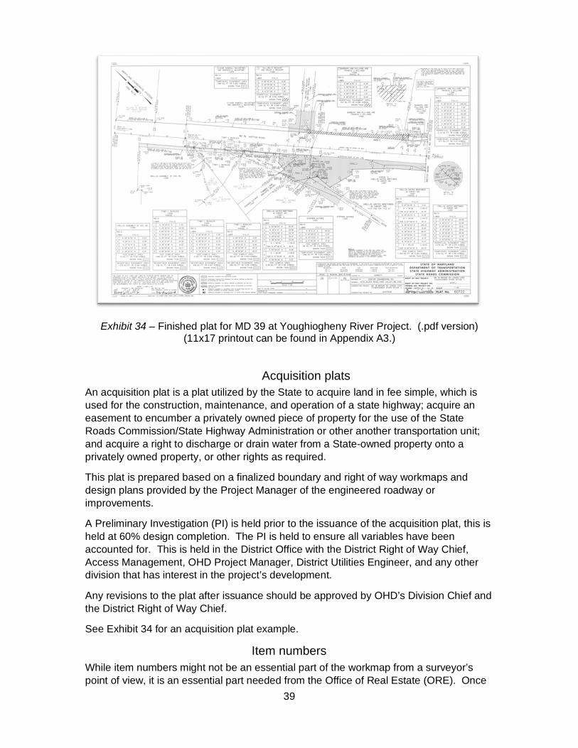
(See Exhibit 33 for an example of a finished plat in CADD and Exhibit 34 for an example of a finished plat in .pdf format)
Exhibit 33 - Finished plat for MD 39 at Youghiogheny River Project (CADD version) (S:\CADD\PSD\Plats\2014\14-3066)
39
Exhibit 34 – Finished plat for MD 39 at Youghiogheny River Project. (.pdf version) (11x17 printout can be found in Appendix A3.)
Acquisition plats An acquisition plat is a plat utilized by the State to acquire land in fee simple, which is used for the construction, maintenance, and operation of a state highway; acquire an easement to encumber a privately owned piece of property for the use of the State Roads Commission/State Highway Administration or other another transportation unit; and acquire a right to discharge or drain water from a State-owned property onto a privately owned property, or other rights as required.
This plat is prepared based on a finalized boundary and right of way workmaps and design plans provided by the Project Manager of the engineered roadway or improvements.
A Preliminary Investigation (PI) is held prior to the issuance of the acquisition plat, this is held at 60% design completion. The PI is held to ensure all variables have been accounted for. This is held in the District Office with the District Right of Way Chief, Access Management, OHD Project Manager, District Utilities Engineer, and any other division that has interest in the project’s development.
Any revisions to the plat after issuance should be approved by OHD’s Division Chief and the District Right of Way Chief.
See Exhibit 34 for an acquisition plat example.
Item numbers While item numbers might not be an essential part of the workmap from a surveyor’s point of view, it is an essential part needed from the Office of Real Estate (ORE). Once

40
the Form 42 (Real Estate Funding report) is completed by the Project Manager and approved, it is submitted to ORE. The item number is assigned to track the parcel that is impacted by any interest taken in the land and represents the land transaction itself. A parcel may have multiple item numbers during its life to identify different land transactions. A plat cannot be issued unless item numbers have been assigned. See Exhibit 35 for an Item Number Request Form example.
As soon as impacts have been analyzed, a request to the District Right of Way Chief should be made to provide item numbers for the parcels affected. A blank form can be found in Appendix H.
Exhibit 35 - Example Item Request Form (Name of property owner on the left and tax account number on the right)
Conveyance plats A conveyance plat is a tool used by the State to dispose of extra land determined to be excess land to an adjoining private owner, to a county government or municipality, or to be auctioned at a public sale. This is accomplished through the Determination of Excess

41
Land Memorandum (DELM) process. Requests for these plats come from ORE or The Secretary’s Office (TSO). Typically, no additional boundary work is needed to prepare these plats. An exception would be if only a portion of the original acquisition is to be conveyed. An example of a conveyance plat can be seen below in Exhibit 36.
Exhibit 36 - Example of a conveyance plat (11x17 printout can be found in Appendix A4.)
Road transfer plats A packet received from ORE should contain:
MOU – Memorandum of Understanding RTA – Road Transfer Agreement Aerial with road transfer area delineated Road transfer item number Any other special instructions If any of these items are missing, contact the requestor
Begin by pulling all plats referenced in ORE’s packet. Confirm that they are all the latest plats covering the transfer area. The plats used for the initial acquisition of the roadway/right of way are also necessary. Next, plot the plats showing the base line, right of way, and existing easements. Verify that the easements are to be transferred. Place the plats on the current coordinate system, if possible. If not, then reference the plat datum used on the north arrow. If all the area to be conveyed is defined and

42
delineated on the existing plats, then a new plat may not be necessary. If a new right of way line showing where the division will be between SHA and the entity receiving the road transfer is needed, then a new plat needs to be created.
Identify the following information from the original acquisition:
Item number Grantor(s) Liber/Folio Deed date or witness date
Make sure all the areas to be transferred are covered.
Create the plat showing the area to be transferred, the new right of way lines, the lines of division from the original acquisition, the station offsets, and the easements, as necessary.
When creating the area to be transferred, use the “Extra Land” metes and bounds box through MCPC. This gives the border shading. Edit the bottom to read “Conveyance Area” instead of “Extra Land Area.” If the area was acquired from a single grantor, then put the “Formerly” citation in the header. If the area was acquired from multiple grantors, then use the following statement in the header:
NOW OR FORMERLY
STATE OF MARYLAND TO THE USE OF THE STATE HIGHWAY ADMINISTRATION OF THE DEPARTMENT OF TRANSPORTATION
The right of way project name and number in the title box and the construction project name and number are the same as the original acquisition plat. If multiple contracts are being used, then list them all. If the plat datum is being used, then remove the control box. If the NAD 27 datum is being used, then try to find the control used to list in the control box. List all books and plats used to create the road transfer plat.
Even if a plat for the road transfer is being created, an accompanying description will be needed. See “Chapter VI – Metes and Bounds Description” for instructions on creating a road transfer description. For an example of a road transfer plat, see Exhibit 37.

43
Exhibit 37 - Road transfer plat (11x17 printout can be found in Appendix A5.)
Donation plats Donation plats are generally created by consultants on behalf of private developers or, occasionally, on behalf of government agencies. For example, as part of a county’s subdivision process, a private developer is often required to donate right of way to the State for future road widening. In these cases, the developer hires a surveyor to prepare the plat that will be referenced in the deed that conveys the additional right of way to the State. Some of the surveyors who prepare donation plats have little experience with SHA plat standards, so the plats are reviewed to ensure that they are consistent with SHA plat requirements. There are two types of donation plats: full-size and scanned image.
Full-size donation plats are similar to other types of SHA plats. They show fee simple lands and easements acquired through donations. In some cases, the developer’s surveyor is using AutoCAD, rather than MicroStation, but the goal is still to create a plat that resembles a standard SHA plat as much as possible.
Scanned image plats are a simpler alternative. Scanned image plats are recorded county subdivision plats that are scanned onto the SHA border. It is critical that SHA review the subdivision plat before it is recorded by the county. The developer’s surveyor will incorporate SHA’s comments, which are typically minor, into the subdivision plat. After the subdivision plat has been approved and recorded by the local county, it is scanned onto mylar inside a SHA plat border by SHA. Donation plats help SHA keep track of the right of way and easements it acquires through the donation process. See Exhibit 38 and Exhibit 39 for examples of a scanned image plat and a full-size donation plat. Donation plat guidelines checklist on can be found in Appendix I.

44
Exhibit 38 – Scanned image plat (Note and metes and bounds box added on the right.) (11x17 printout can be found in Appendix A6.)
Exhibit 39 – Full-size donation plat (11x17 printout can be found in Appendix A7.)

45
Definition plats A definition plat is created to record present conditions of a site. It will show existing right of way lines, base lines, easements, and property lines.
A definition plat is created when the right of way does not appear in a recorded plat or where there is uncertainty in original acquisition from property owners or in cases of highway use by prescription. See Exhibit 40 for an example of a definition plat.
Exhibit 40 – Definition plat (11x17 printout can be found in Appendix A8.)

46
Plat finalization Steps to take a plat from final revised copy to submitted:
1. After a plat has been reviewed by the Assistant Division Chief and revised by the drafter, the plat must be plotted on mylar media. Mylar is the preferred media for archival purposes due to durability.
2. The mylar is then signed, sealed, and dated by the Professional Land Surveyor of record.
3. After the Professional Land Surveyor (PLS) has signed the mylar of the plat is then taken to the Plats and Surveys Division Chief for issuance. The Division Chief will review, sign, and date, thereby officially issuing the plat.
4. After all signatures, the mylar is scanned at 400 dpi minimum quality in .pdf format for PSD archiving purposes. Please verify scan and make sure all four corner coordinates are shown.
5. After the mylar is scanned and verified, fill out and sign the ORE Plat Transmittal Form (included in Appendix J). Make a copy of the transmittal form to take to a member of the assets management team to be uploaded into DARS.
6. Deliver the mylar and transmittal to ORE’s Records and Research Division, located on the second floor of the 211 building. (as of January 2020)

47
Chapter VI – Metes and Bounds Descriptions A metes and bounds description is an intimate part of a deed necessary to define the interest of land conveyed. The description of the property shall be written so that lines of possession and evidence can be retraced clearly. Descriptions shall include courses, distances, intersections, bindings, and calls for landmarks and monumentation to guide future surveyors and/or researchers. In SHA, descriptions are used to convey or transfer property, that SHA no longer has interest in, to another government agency. Metes and bounds descriptions shall be signed by the PLS per COMAR 09.13.06.08 or submitted without a signature as per requirements for what the document will be used for by the requesting party.
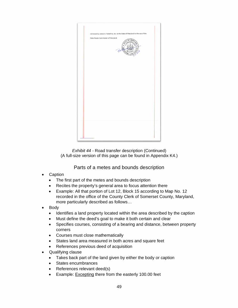
There are 3 distinct types of descriptions used in PSD to convey property. These are the metes and bounds description with plat (See Exhibit 41 and Exhibit 42), the road transfer with plat (See Exhibit 43 and Exhibit 44), and the road transfer without plat.
Exhibit 41 - Portion of a metes and bounds description. (The entirety of this page at full-size can be found in Appendix K1.)

48
Exhibit 42 - Metes and bounds description (Continued) (A full-size version of this page can be found in Appendix K2.)
Exhibit 43 - This road transfer description references a road transfer plat. (A full-size version of this page can be found in Appendix K3.)
49
Exhibit 44 - Road transfer description (Continued) (A full-size version of this page can be found in Appendix K4.)
Parts of a metes and bounds description Caption
The first part of the metes and bounds description Recites the property’s general area to focus attention there Example: All that portion of Lot 12, Block 15 according to Map No. 12
recorded in the office of the County Clerk of Somerset County, Maryland, more particularly described as follows…
Body Identifies a land property located within the area described by the caption Must define the deed’s goal to make it both certain and clear Specifies courses, consisting of a bearing and distance, between property
corners Courses must close mathematically States land area measured in both acres and square feet References previous deed of acquisition
Qualifying clause Takes back part of the land given by either the body or caption States encumbrances References relevant deed(s) Example: Excepting there from the easterly 100.00 feet

50
Augmenting clause Gives a right of usage outside the conveyed, usually easements References relevant deed(s) Example: And granting an easement for road purposes over the westerly 25
feet of the above excepted 100 feet Other Notes
SHA has a set format for how the header and body of the description are written. See Exhibit 41 and Exhibit 42.
The header can be adjusted to suit the need, area to be acquired, easement area, etc.
Only horizontal or grid distance may be listed. An actual datum may not be able to be listed. There may not be any item numbers because a prescriptive easement over a roadway that has been abandoned by SHA is being released. There is not a “one size fits all” formula, just guidance on format.
Exhibit 41 and Exhibit 42 show the format for a metes and bounds description and road transfer without a plat.
Exhibit 43 and Exhibit 44 show the format for a road transfer with a plat. Name the description word document with the item number and road name
as follows: Item 91112 MD 484 Marbury-Pisgah Road RT
A checklist for writing metes and bounds descriptions can be found in Appendix L.

51
Chapter VII - Review Mosaics, workmaps, plats, and descriptions must be reviewed by a co-worker and supervisor. It is required to perform quality assurance and quality compliance (QA/QC) on deliverables before submitting.
Mosaic A mosaic is the visual representation of the research done, as explained in “Chapter II - Mosaics”, and the first deliverable. This document is based on descriptions prepared at different times by different surveyors, so the “puzzle” might not have a perfect fit.
When reviewing a mosaic, important information that should be checked is:
North arrow Bar scale Base line of right of way Right of way Easements Parcels (if this is a boundary mosaic or if lines from parcels were used to set the
right of way on a right of way mosaic) Calls for adjoiners by name, by roadway, by stream or water feature, etc. Other natural or artificial features that would help set boundary Calls for property corner monumentation, (e.g. stones, pipes, and rebar) Preparer and date Recording reference for all documents (e.g. field survey books, liber and folio,
and plat book and page number)

52
Workmap A workmap combines the work performed in the office with the monumentation found during meets and bounds field work. The surveyor decides, based on the research and the field-located evidence, where boundary and right of way lines are determined to be located. See “Chapter IV - Workmaps” for more details and examples. When reviewing work done by another professional surveyor, either in-house or by a consultant, there is some important information to be aware of.
When reviewing a workmap, utilize the workmap checklist found in Appendix M. Important information that should be checked includes:
North arrow with datum identified (NAD 83/91 as of 01/2020) Typical projects are on NAD 83/91 Datum. However, other assignments may
be on a different datum on a task-specific basis. Bar scale Drafting requirements (line type, line weight, etc.) Show monuments found on a metes and bounds survey used to set any base
line or boundary Roads identified with both route number and name Parcel identified with current property owner (Follow guidelines on what
information to include on each parcel.) Show recorded vs field angles and distances.
Plat When reviewing a plat, there are many details to consider, and for that reason, PSD has created a drafter’s checklist to be used when preparing and reviewing a plat. When a plat is finalized and ready for a final review by the Assistant Division Chief, the checklist must be handed in along with the finalized plat. Please check the Appendix I for the latest Drafter’s Checklist. A plat that has been reviewed can be seen in Exhibit 45.
Exhibit 45 – Example of plat with comments (11x17 printout can be found in Appendix A9.)

53
Chapter VIII – GIS and Special Projects
Digital Assets Referencing System This system is only available to all MDOT employees upon request. To access this system, login information must be acquired from the DARS team.
This map is a reference tool for locating areas with prior survey information (workmap or mosaic). The right of way geometry represented in this map was generated either directly by the MDOT SHA PSD or by licensed survey consultants under official contract. Always use the original design data for final deliverables.
An example of layers with PSD information
All Delivered Total Maximum Daily Load (TMDL) R/W - Right of way re-established by the MDOT SHA PSD, at the request of the MDOT SHA Office of Environmental Design’s TMDL Program. Contains workmap or mosaic level information.
OHD Survey Areas - Centerline representations of prior (non-TMDL) survey jobs found on the S Drive, categorized by how well the job was documented. It contains workmap or mosaic level information.
Item Number Pilot - This is a pilot service layer. Georeferenced plats were used to identify a series of property item numbers along a given route. Line and point data layers have been drawn to represent the span of these item numbers relative to the route centerline.
Right of Way Trace Line - This is a pilot service layer. Georeferenced plats were used to trace right of way lines along a given route.
PSD GPS Points - This is a pilot service layer. Complete inventory of the MDOT SHA GPS control points.
54
An example of layers with public information
Maryland SHA Mile points - Mile markers information. Georeferenced Plat Boundaries – Georeferenced plats border with plat number
description. Maryland Parcel Boundaries - This dataset contains tax map parcel polygons of
the entire state.
In addition to the procedure for plat in “Chapter V – Plats”, when finalizing a workmap, the plat leader must fill out a workmap submittal, found in Appendix N. This form is then used to update the “OHD Survey Areas” layer with the workmap information and plat information respectively. The GIS Map is a living document that is always growing. New features can be added in the future.

55
Appendix
11x17 Plats and Plans…………….……………………...….…………...…...A Construction and as-built plan (Exhibit 5)…………..…………….….A1
Design plan title sheet (Exhibit 20)……..………………………….....A2
Finished plat (Exhibit 34)………………………..……………………..A3
Conveyance plat (Exhibit 36)………...…..…………………………...A4
Road transfer plat (Exhibit 37)……………..………………………….A5
Scanned image plat (Exhibit 38)………………………..…………….A6
Full-size donation plat (Exhibit 39)………………...………………….A7
Definition plat (Exhibit 40)………………………………..…………….A8
Plat with comments (Exhibit 45)…………………………..…………..A9
Deed Example (Exhibit 6).…………………………………..………………B Field/Survey Book (Exhibit 17)……………………………….……………...C Types of Easements Used by SHA………………………………………….D Plat Guidelines for Linework…………………………………………………E Plat Guidelines for Text Size………………………………………………...F Drafter’s Checklist………………………………………………….………….G Item Number Request Form……………………………………….…………H Donation Plat Requirements Checklist……………………………………..I ORE Plat Transmittal Form…………………………………………….…….J Descriptions………………………………………………………….…………K
Metes and Bounds Description (Exhibit 41)……….…….…………..K1
Metes and Bounds Description (Last Page) (Exhibit 42)...….……..K2
Road Transfer Description (Exhibit 43)………………………………K3
Road Transfer Description (Last Page) (Exhibit 44)....……………..K4
Metes and Bounds Description Checklist...……………………….……...L Workmap Checklist……………………………………………………………M Workmap Submittal Form……………………………………….……………N