Embed Size (px)
Citation preview

INTERNATIONAL JOURNAL OF c© 2012 Institute for ScientificNUMERICAL ANALYSIS AND MODELING Computing and InformationVolume 9, Number 2, Pages 312–325
THE OBLIQUE WATER ENTRY IMPACT OF A TORPEDO AND
ITS BALLISTIC TRAJECTORY SIMULATION
ZHAOYU WEI, XIUHUA SHI, AND YONGHU WANG
Abstract. To study the water entry ballistic trajectory of a torpedo, the wind tunnel experimenthas been done based on the similarity principle. Then the drag coefficient of the torpedo is gotwhen it enters the water, which is amended by the introduction of continuous supercavitationfactor and local cavity effect factor. The vertical plane motion equations are established to getthe torpedo’s trajectory. The large scale nonlinear transient finite element commercial softwareMSC. dytran is also used to simulate the initial water entry impact of the Disk-Ogive-Head[1]torpedo, including four special high-speed water entry attitude angles. Then the kinematicsparameters as the tail of torpedo submerges in water are input into the motion equation as theinitial conditions. Finally, two parts of the data are combined to get the whole kinematic andkinetic parameters. During the calculation, the ballistic modeling uses the cavitation number todetermine the torpedo’s moving status: in the supercavitation stage, in partial cavity stage or infull wet navigation stage. The simulation results will do reference use to the following trajectorydesign. In addition, the water impact load and over load calculation of high-speed oblique waterentry impact will help to design the intensity of torpedo’s shell.
Key words. Water entry, MSC. dytran, FE simulation, torpedo, over load, trajectory, impactdrag coefficient.
1. Introduction
In modern naval warfare, torpedo and anti-torpedo confrontation is growing morefiercely, improving the concealment of torpedoes is a key issue to be researched,conventional air-dropped torpedo or rocket assisted torpedo usually enters waterwith a parachute [2]. As the target is so large that it can be easily found by theenemy. In addition, when a torpedo enters water with a buffer cap, if the buffer capcouldn’t fully come to pieces, the relic would affect its streamline, and thus affectthe torpedo’s hydrodynamic characteristic. So high speed torpedo’s entering waterwithout a parachute and a buffer cap is a trend.
However, water entry of high-speed naked torpedoes will face enormous fluidimpact force. Perhaps the load could cause damage to its structure, so failureand even damage of internal components cannot be ignored. It is necessary toaccurately compute the fluid and solid interaction and its effect. Therefore, researchon water entry impact of high speed torpedoes and their ballistics trajectory havean important significant background.
As computer-aided engineering technology rapidly develops, finite element anal-ysis software has been widely used in the transient dynamics analysis [3], whichcould be applied in the process of special transient dynamics simulation analysis,especially in high speed torpedo’s water entry impact issues, and it can greatlyimprove the efficiency and save the spending [4]. In practical work, the experi-ment research of water entry impact is not only costly but also difficult to operate.Sometimes the results may not be entirely accurate. The transient nonlinear fi-nite element commercial analysis software MSC. dytran can effectively deal with
Received by the editors November 9, 2009 and, in revised form, April 4, 2010.2000 Mathematics Subject Classification. 35R35, 49J40, 60G40.
312

THE OBLIQUE WATER ENTRY IMPACT OF A TORPEDO AND ETC 313
multi-material fluid-solid coupling problems, it is very appropriate to simulate thedynamic response when a torpedo hits the water.
In the current investigation, the wind tunnel experiment has been done to getthe drag coefficient of the torpedo based on the similarity principle. The continuoussupercavitation factor and local cavity effect factor are introduced to amend thedrag coefficient, which is combined with the vertical plane motion equations to getthe torpedo’s tracks. The finite element software MSC. Dytran is used to simulatethe initial water entry impact of a Disk-Ogive-Head[1] torpedo, including four spe-cial high-speed water entry attitude angles. When the kinematics parameters aregot, they are input into the motion equation as the initial conditions. Then twoparts of the data are combined to get the whole kinematic and kinetic parameters.
2. Dytran program
2.1. Software description. MSC. Dytran[5] is a large nonlinear transient finiteelement commercial software, which could be used in aviation, aerospace, marineand automotive fields, as well as a wide range of applications. In MSC. Dytran thesolid structure uses Lagrange elements; fluid (including air, water) uses Euler ele-ments. The interface between the two is defined as fluid-solid coupling surface. Thecoupling algorithms include general coupling algorithm and Arbitrary Lagrangian-Eulerian (ALE) Coupling. By directly grid-coupling Lagrange mesh and Eulermesh the kinematics parameters and motion parameters on the coupling surfacecan be automatically and accurately calculated and outputted at each time step.In this process, on one hand, Euler pressure caused by material flow through thecoupling algorithm automatically loads on the structure grid; on the other hand,the deformation of the structure grid will in turn affects the flow of Euler materialand pressure values. So the interaction of structure deformation and fluid makes itpossible to get the solution of fluid-solid coupling problem.
2.2. Numerical model. In this paper, all the output parameters and model usethe International Units. The finite element model of the torpedo is shown in figure1. Euler fluid region is divided into two parts, the upper part is air domain, withthe size of 1.2m∗1.2m∗0.8m. It is divided into 200,000 Euler elements, filled withideal compressible gas. The air domain is described by Gamma state equation [6]:
(1) p = (γ − 1)ρe,
where p is the air pressure, γ is the ratio of specific heat, taken as 1.4, ρ is theair density, taken as 1.2, e is the specific internal energy of unit mass. The initialpressure for the air region takes a standard atmospheric pressure of 0.1013Pa.According to Eq. (1) the initial e of air domain could be calculated as 211,041J/g.
The lower part is the water domain, with the size of 1.2m∗1.2m∗1.5 m, which isdivided into 300,000 Euler elements. Non-viscous and compressible fluid mediumis used to fill these elements. The pressure of the water region is described by thepolynomial equation of state [6], shown as
(2) p =
a1µ+ a2µ2 + a3µ
3 + (b0 + b1µ)ρ0
µ > 0, incompression
a1µ+ (b0 + b1µ)ρ0e
µ < 0, intension
,
where p is the pressure of water, µ = ρ/ρ0 − 1, ρ is the density of sea water, ρ0 isthe reference density of water. The true density of sea water takes 1020 m/s3, thereference water density takes 1000 m/s3, e is specific internal energy per unit mass.
314 Z. WEI, X. SHI, AND H. WANG
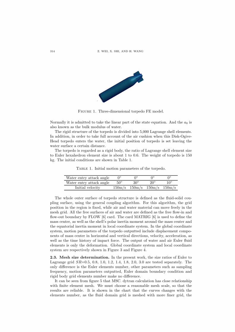
Figure 1. Three-dimensional torpedo FE model.
Normally it is admitted to take the linear part of the state equation. And the a0 isalso known as the bulk modulus of water.
The rigid structure of the torpedo is divided into 5,000 Lagrange shell elements.In addition, in order to take full account of the air cushion when this Disk-Ogive-Head torpedo enters the water, the initial position of torpedo is set leaving thewater surface a certain distance.
The torpedo is regarded as a rigid body, the ratio of Lagrange shell element sizeto Euler hexahedron element size is about 1 to 0.6. The weight of torpedo is 150kg. The initial conditions are shown in Table 1.
Table 1. Initial motion parameters of the torpedo.
Water entry attack angle 0◦ 0◦ 0◦ 0◦
Water entry attack angle 50◦ 30◦ 20◦ 10◦
Initial velocity 150m/s 150m/s 150m/s 150m/s
The whole outer surface of torpedo structure is defined as the fluid-solid cou-pling surface, using the general coupling algorithm. For this algorithm, the gridposition in the region is fixed, while air and water material can move freely in themesh grid. All the free surfaces of air and water are defined as the free flow-in andflow-out boundary by FLOW [6] card. The card MATRIG [6] is used to define themass center, as well as the shell’s polar inertia moment around the mass center andthe equatorial inertia moment in local coordinate system. In the global coordinatesystem, motion parameters of the torpedo outputted include displacement compo-nents of mass center in horizontal and vertical directions, velocity, acceleration, aswell as the time history of impact force. The output of water and air Euler fluidelements is only the deformation. Global coordinate system and local coordinatesystem are respectively shown in Figure 3 and Figure 4.
2.3. Mesh size determination. In the present work, the size ratios of Euler toLagrange grid SR=0.5, 0.8, 1.0, 1.2, 1.4, 1.8, 2.0, 3.0 are tested separately. Theonly difference is the Euler elements number, other parameters such as samplingfrequency, motion parameters outputted, Euler domain boundary condition andrigid body grid elements number make no difference.
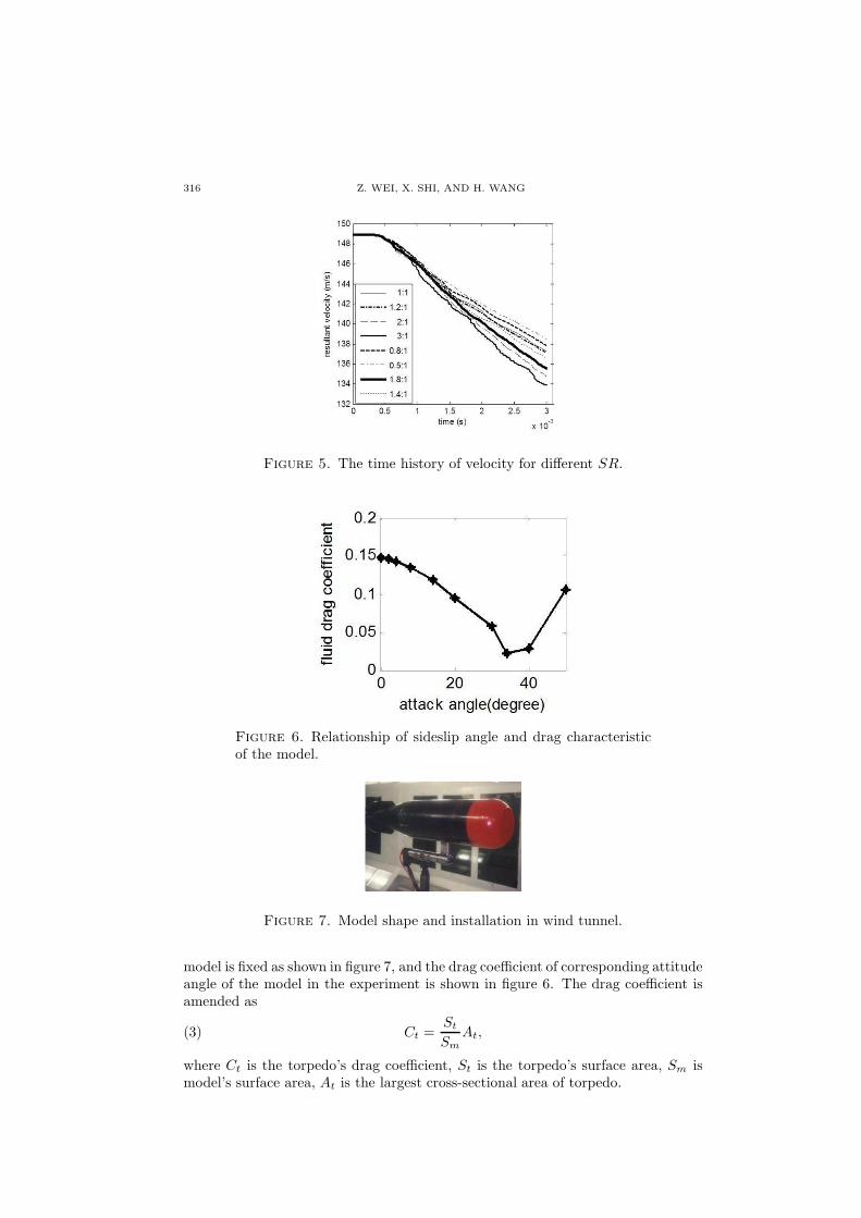
It can be seen from figure 5 that MSC. dytran calculation has close relationshipwith finite element mesh. We must choose a reasonable mesh scale, so that theresults are reliable. It is shown in the chart that the curves changes with theelements number, as the fluid domain grid is meshed with more finer grid, the

THE OBLIQUE WATER ENTRY IMPACT OF A TORPEDO AND ETC 315
Figure 2. Three-dimensional water FE model.
Figure 3. The global coordinate system.
Figure 4. The local coordinate system.
curves becomes more smooth and straight, with an upward trend moving closerbetween each other. In this paper, for taking full account of time-consuming andcomputer reliability, the grid ratio is chosen as 0.6 to 1.0.
3. Theoretical modeling
3.1. Experiment and drag coefficient testing. The experiment was performedin NF3 wind tunnel in Northwestern Polytechnical University in China. Mechanicsparameters of a small model which is similar to the torpedo researched in this paperwere tested. The main parameter is the relationship between attitude angle andfluid drag coefficient. In the experiment, the model has the same cross sectionalarea with the torpedo, which is the characteristics area for drag coefficient. Aftertesting, the drag coefficient is amended with the whole area of the torpedo. The
316 Z. WEI, X. SHI, AND H. WANG
Figure 5. The time history of velocity for different SR.
Figure 6. Relationship of sideslip angle and drag characteristicof the model.
Figure 7. Model shape and installation in wind tunnel.
model is fixed as shown in figure 7, and the drag coefficient of corresponding attitudeangle of the model in the experiment is shown in figure 6. The drag coefficient isamended as
(3) Ct =St
Sm
At,
where Ct is the torpedo’s drag coefficient, St is the torpedo’s surface area, Sm ismodel’s surface area, At is the largest cross-sectional area of torpedo.
THE OBLIQUE WATER ENTRY IMPACT OF A TORPEDO AND ETC 317
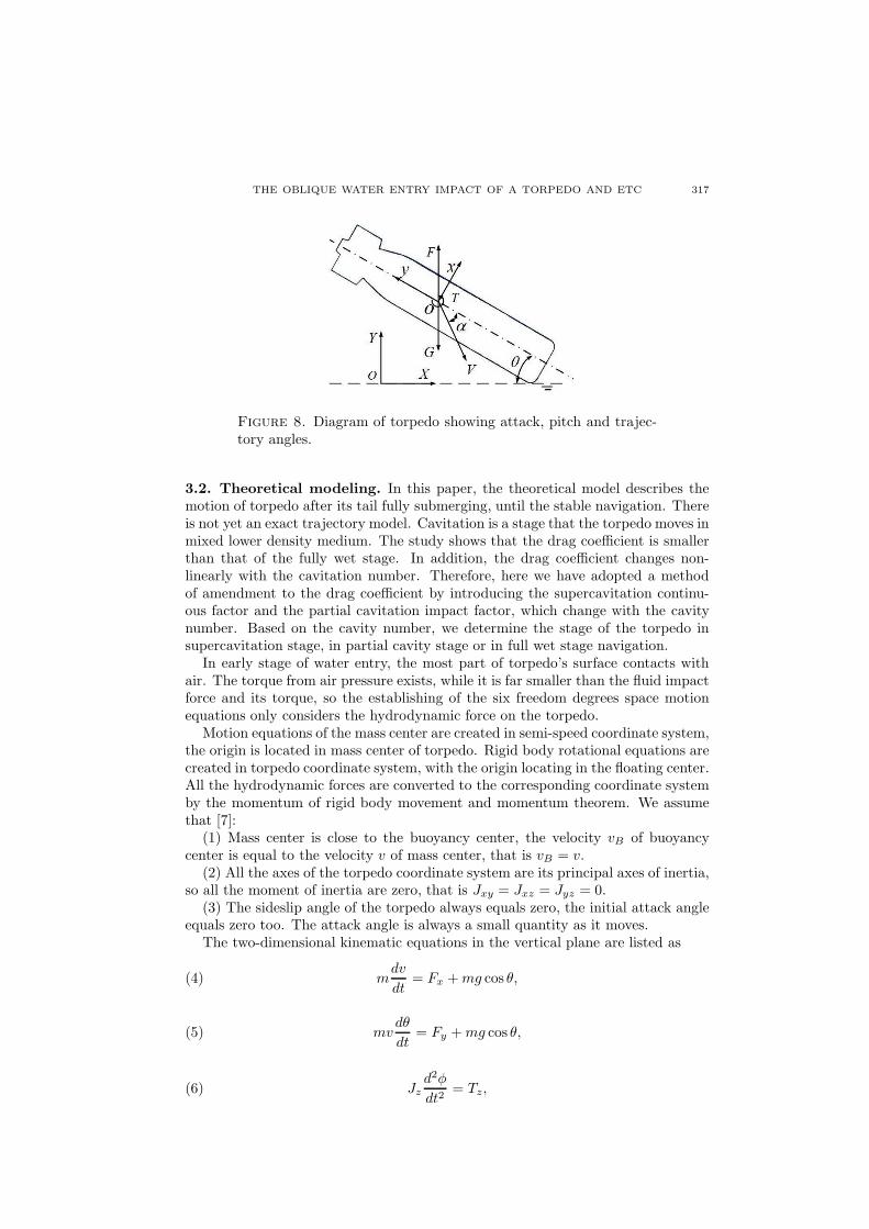
Figure 8. Diagram of torpedo showing attack, pitch and trajec-tory angles.
3.2. Theoretical modeling. In this paper, the theoretical model describes themotion of torpedo after its tail fully submerging, until the stable navigation. Thereis not yet an exact trajectory model. Cavitation is a stage that the torpedo moves inmixed lower density medium. The study shows that the drag coefficient is smallerthan that of the fully wet stage. In addition, the drag coefficient changes non-linearly with the cavitation number. Therefore, here we have adopted a methodof amendment to the drag coefficient by introducing the supercavitation continu-ous factor and the partial cavitation impact factor, which change with the cavitynumber. Based on the cavity number, we determine the stage of the torpedo insupercavitation stage, in partial cavity stage or in full wet stage navigation.
In early stage of water entry, the most part of torpedo’s surface contacts withair. The torque from air pressure exists, while it is far smaller than the fluid impactforce and its torque, so the establishing of the six freedom degrees space motionequations only considers the hydrodynamic force on the torpedo.
Motion equations of the mass center are created in semi-speed coordinate system,the origin is located in mass center of torpedo. Rigid body rotational equations arecreated in torpedo coordinate system, with the origin locating in the floating center.All the hydrodynamic forces are converted to the corresponding coordinate systemby the momentum of rigid body movement and momentum theorem. We assumethat [7]:
(1) Mass center is close to the buoyancy center, the velocity vB of buoyancycenter is equal to the velocity v of mass center, that is vB = v.
(2) All the axes of the torpedo coordinate system are its principal axes of inertia,so all the moment of inertia are zero, that is Jxy = Jxz = Jyz = 0.
(3) The sideslip angle of the torpedo always equals zero, the initial attack angleequals zero too. The attack angle is always a small quantity as it moves.
The two-dimensional kinematic equations in the vertical plane are listed as
(4) mdv
dt= Fx +mg cos θ,
(5) mvdθ
dt= Fy +mg cos θ,
(6) Jzd2φ
dt2= Tz,

318 Z. WEI, X. SHI, AND H. WANG
(7) ωz =dθ
dt,
(8)dx
dt= v cosΘ,
(9)dy
dt= v sinΘ,
and
(10) Θ = θ − α,
where, m is the mass of torpedo, Jz is the moment of inertia of torpedo, α isthe attack angle, Tz is the torque of fluid force on torpedo around z axis in theglobal coordinate system, θ is the attitude angle, v is torpedo’s speed and Θ is thetrajectory angle. Fx and Fy[8] are the fluid force components on the torpedo in thehorizontal and vertical directions. Before the cavity collapses, they are calculatedby a semi-empirical formula on the basis of amendment to the experiment data.For in the initial impact stage, dynamics parameters have been calculated withsoftware, so now they are calculated by the following formula:
(11) Fx =[
0.25R+ 0.22Ls(L− Lf )]
ρLw(vx + ωzLw)2,
(12) Fy =[
0.25R+ 0.22Ls(L− Lf )]
ρLw(vy + ωzLw)2∗ sign(vx),
and
Tz = 0.125ρR[
L2w(vy + ωzLw)
2− (Lw − Lc)
2vy + ωzLw)2]
ρLw(vy +(13)
+ ωzLw)2∗ sign(vx) + 0.22ρLs(L− Lf )L
2w(vy − ωzd)
2,
where R is the radius of the torpedo, with unit of meter, L is torpedo’s length, withthe unit of meter too, Ls is the length of fin span, sign is the symbol function.
The drag coefficient can be calculated as
(14) Cx = C′x − 8α2,
where α is attack angle, C′x is the drag coefficient, which is related to cavity status.
Here, an approach of amendment to the drag coefficient is adopted. Duringthe water entry stage, the drag coefficient is related to fin, rudder, steady flowloop, as well as head shape and cavitation status. The supercavitation continuancefactor and the local cavity impact factor are introduced, which changes with thecavitation number. Based on the cavitation number, the status of the torpedo isdetermined, whether in supercavitation stage, in local cavitation stage or in totallywet navigation stage. First of all, quotient of critical sea water saturation vaporpressure to supercavitation continuance factor is calculated and contrasted to thecavitation number, making the following judgments:
If the cavitation number is less than or equal to the quotient, thus the torpedois in supercavitation navigation stage.
If the cavitation number is bigger than quotient and less than critical seawatersaturation vapor pressure, thus the torpedo is in partial cavitation navigation stage.
If the cavitation number is greater than or equal to critical seawater saturationvapor pressure, thus the torpedo moves in totally wet stage.
Then in different stage, the drag coefficient is amended correspondingly.
THE OBLIQUE WATER ENTRY IMPACT OF A TORPEDO AND ETC 319
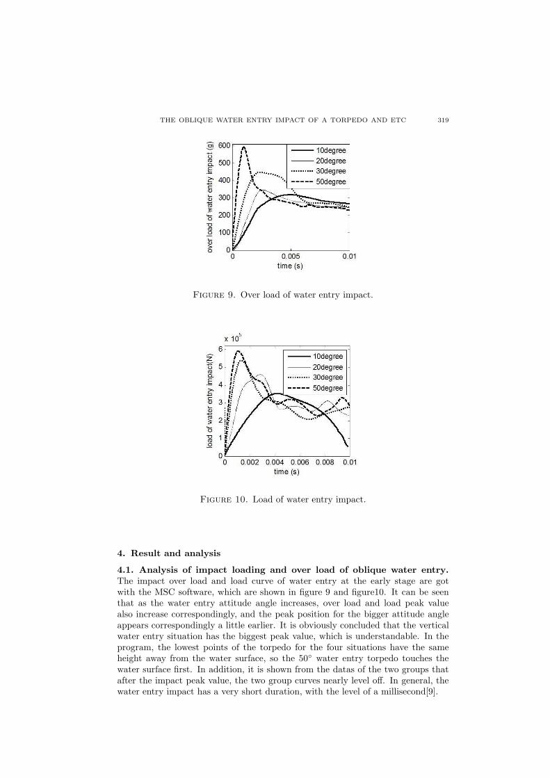
Figure 9. Over load of water entry impact.
Figure 10. Load of water entry impact.
4. Result and analysis
4.1. Analysis of impact loading and over load of oblique water entry.
The impact over load and load curve of water entry at the early stage are gotwith the MSC software, which are shown in figure 9 and figure10. It can be seenthat as the water entry attitude angle increases, over load and load peak valuealso increase correspondingly, and the peak position for the bigger attitude angleappears correspondingly a little earlier. It is obviously concluded that the verticalwater entry situation has the biggest peak value, which is understandable. In theprogram, the lowest points of the torpedo for the four situations have the sameheight away from the water surface, so the 50◦ water entry torpedo touches thewater surface first. In addition, it is shown from the datas of the two groups thatafter the impact peak value, the two group curves nearly level off. In general, thewater entry impact has a very short duration, with the level of a millisecond[9].
320 Z. WEI, X. SHI, AND H. WANG
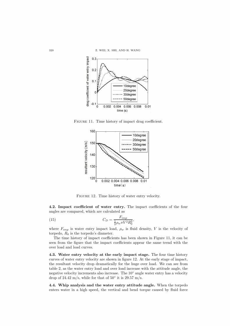
Figure 11. Time history of impact drag coefficient.
Figure 12. Time history of water entry velocity.
4.2. Impact coefficient of water entry. The impact coefficients of the fourangles are compared, which are calculated as
(15) CD =Fimp
12ρwπV 2R2
0
,
where Fimp is water entry impact load, ρw is fluid density, V is the velocity oftorpedo, R0 is the torpedo’s diameter.
The time history of impact coefficients has been shown in Figure 11, it can beseen from the figure that the impact coefficients appear the same trend with theover load and load curves.
4.3. Water entry velocity at the early impact stage. The four time historycurves of water entry velocity are shown in figure 12. At the early stage of impact,the resultant velocity drop dramatically for the huge over load. We can see fromtable 2, as the water entry load and over load increase with the attitude angle, thenegative velocity increments also increase. The 10◦ angle water entry has a velocitydrop of 24.42 m/s, while for that of 50◦ it is 29.57 m/s.
4.4. Whip analysis and the water entry attitude angle. When the torpedoenters water in a high speed, the vertical and bend torque caused by fluid force
THE OBLIQUE WATER ENTRY IMPACT OF A TORPEDO AND ETC 321
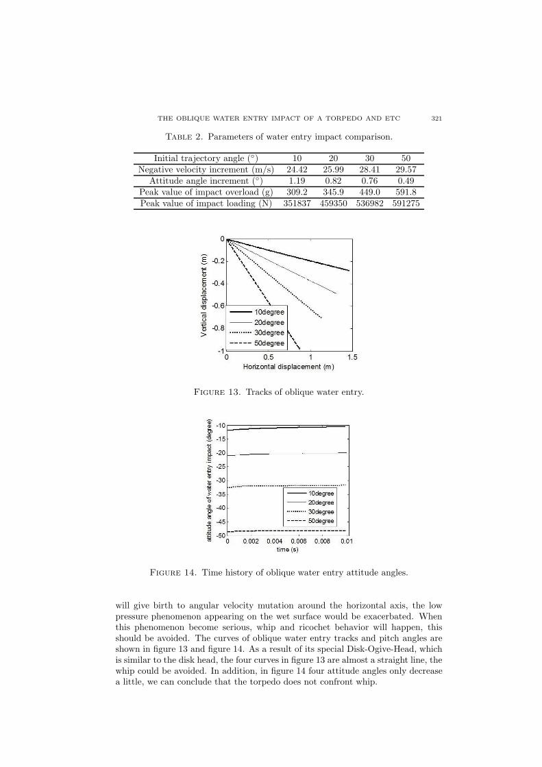
Table 2. Parameters of water entry impact comparison.
Initial trajectory angle (◦) 10 20 30 50Negative velocity increment (m/s) 24.42 25.99 28.41 29.57
Attitude angle increment (◦) 1.19 0.82 0.76 0.49Peak value of impact overload (g) 309.2 345.9 449.0 591.8Peak value of impact loading (N) 351837 459350 536982 591275
Figure 13. Tracks of oblique water entry.
Figure 14. Time history of oblique water entry attitude angles.
will give birth to angular velocity mutation around the horizontal axis, the lowpressure phenomenon appearing on the wet surface would be exacerbated. Whenthis phenomenon become serious, whip and ricochet behavior will happen, thisshould be avoided. The curves of oblique water entry tracks and pitch angles areshown in figure 13 and figure 14. As a result of its special Disk-Ogive-Head, whichis similar to the disk head, the four curves in figure 13 are almost a straight line, thewhip could be avoided. In addition, in figure 14 four attitude angles only decreasea little, we can conclude that the torpedo does not confront whip.
322 Z. WEI, X. SHI, AND H. WANG
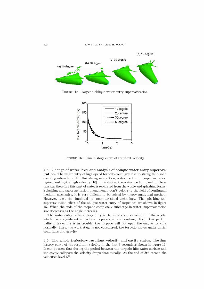
Figure 15. Torpedo oblique water entry supercavitation.
Figure 16. Time history curve of resultant velocity.
4.5. Change of water level and analysis of oblique water entry supercav-
itation. The water entry of high-speed torpedo could give rise to strong fluid-solidcoupling interaction. For this strong interaction, water medium in supercavitationregion could get a high velocity [10]. In addition, the water medium couldn’t beartension; therefore this part of water is separated from the whole and splashing forms.Splashing and supercavitation phenomenon don’t belong to the field of continuummedium mechanics, it is very difficult to be solved by theory analytical method.However, it can be simulated by computer aided technology. The splashing andsupercavitation effect of the oblique water entry of torpedoes are shown in figure15. When the ends of the torpedo completely submerge in water, supercavitationsize decreases as the angle increases.
The water entry ballistic trajectory is the most complex section of the whole,which has a significant impact on torpedo’s normal working. For if this part ofballistic trajectory is in trouble, the torpedo will not open the engine to worknormally. Here, the work stage is not considered, the torpedo moves under initialconditions and gravity.
4.6. The whole trajectory resultant velocity and cavity status. The timehistory curve of the resultant velocity in the first 3 seconds is shown in figure 16.It can be seen that during the period between the torpedo hits water surface andthe cavity collapses the velocity drops dramatically. At the end of 3rd second thevelocities level off.

THE OBLIQUE WATER ENTRY IMPACT OF A TORPEDO AND ETC 323
Figure 17. Water entry track curve.
Cavitation situation of torpedo in its initial trajectory is shown in table 3. Thecavity of torpedo is tightly related to its head type, in some cases the head can becompare as a cavitation device. In addition, the initial velocity and angle also hasgreat influence on cavitation. From the table, as the attitude angle becomes smaller,the torpedo’s supercavitation navigation and partially cavitation navigation lastlonger. In addition, the bigger attitude angle torpedo relatively also has a biggerstable velocity, as the smaller attitude angle one could get bigger drag in stablenavigation.
Table 3. Cavitation status of torpedo in different water entryangle (second, s)
Angles Supercavitationnavigation
Local cavitynavigation
Full wetnavigation
Steadyvelocity
50◦ 0-0.24s 0.24-0.72s 0.72-3s 10.55m/s30◦ 0-0.29s 0.29-0.81s 0.81-3s 10.23m/s20◦ 0-0.38s 0.38-0.93s 0.93-3s 9.94m/s10◦ 0-0.43s 0.43-1.10s 1.10-3s 9.65m/s
4.7. Whole water entry ballistic trajectory angle and curve. For the obliquewater entry of many Conical-Nosed-head and Ogive-head torpedoes, the ultimategoal is to avoid whip and ricochet behaviors. The best way to judge the whip oftorpedoes is to research the trend of track curves and the time course of trajectoryangle, which are shown in figure 17 and figure 18.
As it can be seen from the charts, water entry of this Disk-Ogive-head torpedois similar to that of a cylinder head torpedo, which will get an immersed torque.So the whip phenomenon couldn’t happen. During initial stage of water entry,because of its special head, the torpedo almost moves along a straight line. Whenthe velocity drops to a certain extent, as well as the role of gravity, the trajectorycurve has a downward trend in the latter stage. In addition, during the navigating,due to the role of the tail fin, the rudder, and steady flow loop, if the torpedo doesnot start the engine to work in very long time, the trajectory angle will tend to90◦.

324 Z. WEI, X. SHI, AND H. WANG
Figure 18. Time history curve of trajectory angle.
5. Conclusion
In this paper, the time history regulation of some important kinematics and dy-namics parameters of torpedo are deeply studied, so that we can have a detailedunderstanding of the process of torpedo’s entering the water. The torpedo’s tra-jectory is divided into two parts, the initial water entry impact stage and the stageafter the tail fully submerging. During the first stage, MSC. dytran software isapplied to get the load, over load, velocity and the displacement. Water entryimpact duration is very short, about a millisecond, while the hydrodynamic forcemay cause damage to its head and has a great influence on the torpedo trajec-tory behavior. The vertical movement equations are got by the introduction ofsupercavitation continuous factor and local cavitation impact factor to amend thetorpedo drag coefficient. The drag coefficient needed to be amended is tested inthe wind tunnel in Northwestern Polytechnical University. Then two parts of dataare combined together to get the whole trajectory. From the analysis, the initialvelocity and angle has a great influence on the ballistic behavior, while for this typeof torpedo whip couldn’t happen when it hits the water surface as angles of 10◦,20◦, 30◦ and 50◦ for its Disk-Ogive-Head. So the torpedo could start the engine towork when the cavity completely collapses.
References
[1] Wang Yonghu. Dynamic Response Analysis of Airborne Torpedo and Deep-mine duringWater-Entry Impact and Research of the Relative Technology. Ph. D, Northwestern Poly-technical University, 2008
[2] Yang Shixing, Li Naixing, Xu Xuanzhi. Air-Drop torpedo technology. Yunnan: Yunnan Sci-ence and Technology Press, 2001
[3] C. M. Seddon, M. Moatamedi. Review of water entry with applications to aerospace struc-tures. International Journal of Impact Engineering, 32(2006) 1045-1067
[4] Lu Zhonghua. Theoretical Analysis and Numerical Simulation of Ogive-Nose Projectiles Pen-etrating into Water and Sand Medium. Master, Institute of Structural Mechanics ChinaAcademy of Engineering Physics Mianyang, Sichuan, 2002
[5] Dytran 2008 r1 Reference Manual[6] Dytran 2008 r1 Theory Manual[7] Zhang Yuwen, Torpedo Profile design. Xi’an: Northwestern Polytechnical University Press,
1998[8] Zhang Yuwen, trajectory and ballistic design of torpedo. Xi’an: Northwestern Polytechnical
University Press, 1999

THE OBLIQUE WATER ENTRY IMPACT OF A TORPEDO AND ETC 325
[9] Torpedo mechanics Edit group. Torpedo mechanics. Beijing: National Defense Industry Press,1992
[10] Zhang Yuwen, Theory and Application of Cavitation. Xi’an: Northwestern PolytechnicalUniversity lectures, 2007
School of Marine, Northwestern Polytechnical University, Xi’an, 710072, ChinaE-mail : [email protected] and [email protected]
Flight Technology College, Civil Aviation Flight University of China, Guanghan, 618307, ChinaE-mail : [email protected]