Embed Size (px)
Citation preview

The finite element modeling of spiral ropes
Juan Wu
Received: 3 February 2014 / Revised: 25 August 2014 / Accepted: 27 September 2014 / Published online: 16 October 2014
� The Author(s) 2014. This article is published with open access at Springerlink.com
Abstract Accurate understanding the behavior of spiral rope is complicated due to their complex geometry and complex
contact conditions between the wires. This study proposed the finite element models of spiral ropes subjected to tensile
loads. The parametric equations developed in this paper were implemented for geometric modeling of ropes. The 3D
geometric models with different twisting manner, equal diameters of wires were generated in details by using Pro/
ENGINEER software. The results of the present finite element analysis were on an acceptable level of accuracy as
compared with those of theoretical and experimental data. Further development is ongoing to analysis the equivalent
stresses induced by twisting manner of cables. The twisting manner of wires was important to spiral ropes in the three wire
layers and the outer twisting manner of wires should be contrary to that of the second layer, no matter what is the first
twisting manner of wires.
Keywords Open spiral ropes � Finite element method � Tensile force
1 Introduction
At the present time, spiral ropes are widely used in light-
weight cable-supported structural systems such as sports
stadia, suspended bridges and large Ferris wheels. A rope
can be a critical load carrier of these structures (Beltran and
Williamson 2011; Stanova et al. 2011a).
With the increase of demand in predicting the behavior
of ropes, many advanced digital techniques had been used
in the strand and rope analysis. Computer-aided design and
the finite element method created powerful sophisticated
tools for the modeling and analysis of ropes. Judge et al.
(2012) developed full 3D elastic–plastic finite element
models of the multi-layer spiral strand cables subjected to
quasi-static axial loading using LS-DYNA. Nawrocki and
Labrosse (2000) presented a finite element model of a
simple straight wire rope strand and studied all the possible
inter-wire motions. The role of contact conditions in pure
axial loading and axial loading combined with bending
were investigated. Stanova et al. (2011b) established a
geometric model of a multi-layered strand by CATIA V5
and analyzed force-strain relationship of the strand by
ABAQUS/Explicit. Jiang et al. (2000, 2008), Jiang (2012)
performed concise finite element models for 1 9 7 wire
strand under axial extension and pure bending load, and
studied the contact stress among wires, wire radial dis-
placement, global response of the strand and predicted the
detailed progressive nonlinear plastic behaviors of the
strand wires. Ma et al. (2008, 2009) reported the 6 9 19
IWS right lang lay and right ordinary lay rope models with
ANSYS software. Wang et al. (2012, 2013) proposed finite
element models for 6 9 19 wire rope from the viewpoint
of determination of fretting parameters. Many scholars
(Bradon et al. 2007; Ghoreishi et al. 2007a, b; Usabiaga
and Pagalday 2008; Argatov 2011; Beltran and Williamson
2011; Paczelt and Belezna 2011; Beltra’n and Vargas
2012; Prawoto and Mazlan 2012) dealt with theoretical
models, fiber ropes and broken ropes using 3D finite ele-
ment analyses.
J. Wu (&)
College of Mechanical Engineering, Taiyuan University of
Technology, Taiyuan 030024, China
e-mail: [email protected]
123
Int J Coal Sci Technol (2014) 1(3):346–355
DOI 10.1007/s40789-014-0038-x

However, few models with different twisting manners of
open spiral ropes had been reported.
In this study, three geometric models of open spiral wire
rope 1 9 37 with different twisting manners of wires were
built by CAD software Pro/ENGINEER. The models were
imported into the ANSYS/Workbench. Behavior of the
models obtained from finite element analysis was com-
pared with theoretical and experimental data. The effect of
twisting manner on open spiral rope was analyzed.
2 Geometric models generation
2.1 The parameters of models
The cross-section of an open spiral rope 1 9 37 with a
structure of wires 1 ? 6 ? 12 ? 18 in the three wire
layers is shown in Fig. 1.
In wire ropes (Feyrer 2007), spiral ropes were round
strands as they had an assembly of layers of wires laid
helically over a center with at least one layer of wires being
laid in the opposite direction to that of the outer layer. To
predict the effect of twisting manner on open spiral rope
1 9 37 under tensile loads, three cables with different
twisting manners and equal diameters of wires are mod-
eled. The parameters of the three investigated ropes (Feyrer
2007) are shown in Table 1. The lay radius of wires in the
individual layers of the strand is
r1 ¼ d0 þ d1
2¼ 1:35 þ 1:25
2¼ 1.3 mm
r2 ¼ r1 þd1 þ d2
2¼ 1.3 þ 1:25 þ 1:25
2¼ 2.55 mm
r3 ¼ r2 þd2 þ d3
2¼ 2.55 þ 1:25 þ 1:25
2¼ 3.8 mm
2.2 CAD modeling
The parameter of the helical curve of the wire centerline in
a straight spiral rope as fellows (Feyrer 2007):
x ¼ �r � sin /
y ¼ r � cos /
z ¼ r
tan a� /
hw ¼ 2p � r
tan aj j
ð1Þ
where / is the angle of rotation (the direction of rotation in
anti-clockwise is positive, the clockwise is negative), hw is
lay length, a is the angle of lay and r ¼ ri ði ¼ 0, 1, 2, 3)
(see Fig. 2).
The lay length of first layer is
Fig. 1 The structure of an open spiral rope 1 9 37
Table 1 The parameters of models
Model Layer No. of
wires
Diameters
of the wires
(mm)
Lay
angle a(�)
Lay
radius
(mm)
Model 1 Center wire 1 1.35 0 0
1 6 1.25 14 1.3
2 12 1.25 14 2.55
3 18 1.25 14 3.8
Model 2 Center wire 1 1.35 0 0
1 6 1.25 14 1.3
2 12 1.25 14 2.55
3 18 1.25 14 3.8
Model 3 Center wire 1 1.35 0 0
1 6 1.25 14 1.3
2 12 1.25 14 2.55
3 18 1.25 14 3.8
Fig. 2 Wire space curve in a straight spiral rope
The finite element modeling of spiral ropes 347
123

hw1 ¼ 2pr1
tan a1
¼ 2 � 3:14 � 1:33
tan 14¼ 32:74 mm
The lay length of second layer is
hw2 ¼ 2pr2
tan a2
¼ 2 � 3:14 � 2:55
tan 14¼ 64:23 mm
The lay length of third layer is
hw3 ¼ 2pr3
tan a3
¼ 2 � 3:14 � 3:8
tan 14¼ 96:42 mm
The helical curve of the wire centerline of rope can be
represented by cylindrical coordinates in PRO/ENGI-
NEER. The spiral curve in cylindrical coordinates is
written as
R ¼ r
theta ¼ 360 � n � t
z ¼ t � h
ð2Þ
where r is the radius of helix, n is the number of helix, the
valve of t between 0 and 1, and h the pitch of helix.
By Eq. (2), turn Eq. (1) into Eq. (3) as the following:
x ¼ r � cosð360 � n � t)
y ¼ r � sinð360 � n � tÞz ¼ t � h
ð3Þ
The defined geometric parametric equations are used to
generate the spatial curves of the wires centerline in the
individual layers of the rope (see Table 2).
In Pro/ENGINEER, the helical curve of the wire cen-
terline in first layer of model 1 is constructed according to
equations (see Table 2). The wire is generated by the
sweep function and arrayed the wire in accordance with the
number of wires in first layer. Consequently, the generation
of six wires in first layer is finished. The mentioned
approach is repeated for the other wires in all layers of the
rope. Topology of the generated wires in the second, third
layer and core wire. It should be noted that wires of all
layers are modeled as the same way whereas the adequate
parametric equations with the corresponding values of the
wire diameter and the lay radius for the actual layer must
be used.
The other two models are created analogously. Three
models of spiral ropes are shown in Fig. 3. It can be seen
from Fig. 3a that the twisting manner of wires in the first
layer of the first model is clockwise, that of the second layer
is anti-clockwise and that of the third layer is clockwise. The
twisting manner in the first layer of second model is clock-
wise, that of the second layer and third layer is anti-clockwise
(see Fig. 3b). The twisting manner in the first layer of third
model is anti-clockwise, that of the second layer is anti-
clockwise and third layer is clockwise (see Fig. 3c).
3 The generation of 3D FE models
The geometric models of spiral ropes created in PRO/
ENGINEER are imported into the finite element software
of ANSYS/Workbench, which are used for finite element
numerical analysis. These CAD models are exported as XT
files to ANSYS/Workbench software.
3.1 Material properties and contacts
The assumed modulus of elasticity of the wire material is
E = 188 GPa, the density is q = 7,800 kg/m3, the Pois-
son’s ratio is v = 0.3 (Beltran and Williamson 2011).
The frictional contact types are defined between the sur-
faces of the individual adjacent wires of ropes. The coefficient
Table 2 The equations of helical curve
Model Layer i Equations of helical curve
Model 1 1 x ¼ 1:3 sin 96:4232:74
� t � 360� �
y ¼ 1:3 cos 96:4232:74
� t � 360� �
z ¼ 1:3t � p � 2 � 96:4232:74
tan14
2 x ¼ �2:55sin 96:42
32.74� t � 360
� �
y ¼ 2:55 sin 96:4232:74
� t � 360� �
z ¼ 2:55t � p � 2 � 96:4232:74
tan14
3 x ¼ 3:82 sinðt � 360)
y ¼ 3:82 cosðt � 360)
z ¼ 3:82t � p � 2
tan14
Model 2 1 x ¼ 1:3 sin 96:4232:74
� t � 360� �
y ¼ 1:3 cos 96:4232:74
� t � 360� �
z ¼ 1:3t � p � 2 � 96:4232:74
tan14
2 x ¼ �2:55 sin 96:4232:74
� t � 360� �
y ¼ 2:55 sin 96:4232:74
� t � 360� �
z ¼2:55t � p � 2 � 96:42
32:74
tan 14
3 x ¼ �3:82 sinðt � 360)
y ¼ 3:82 cosðt � 360)
z ¼ 3:82t � p � 2
tan 14
Model 3 1 x ¼ �1:3 sin 96:4232:74
� t � 360� �
y ¼ 1:3 cos 96:4232:74
� t � 360� �
z ¼1:3t � p � 2 � 96:42
32:74
tan 14
2 x ¼ �2:55 sin 96:4232:74
� t � 360� �
y ¼ 2:55 sin 96:4232:74
� t � 360� �
z ¼2:55t � p � 2 � 96:42
32:74
tan 14
3 x ¼ 3:82 sinðt � 360)
y ¼ 3:82 cosðt � 360)
z ¼ 3:82t � p � 2
tan 14
348 J. Wu
123

of friction between wires is l ¼ 0.2. The pairs of contact are
329. The formulation of contact is Augmented Lagrange.
3.2 Finite element mesh generation
The mesh method is sweep method. The size of element in
sweep method is 0.5 mm. Face meshes with dimensions of
0.3 mm are used for the finite element analysis. The sizing of
relevance center is fine. The skewness of mesh size is 0.56.
The meshes for each wire are generated independently. Three
models are composed of 195,395 elements and 941,117 nodes.
3.3 Supports
The supports of one end in the models are fixed support
(fully fixed in all degrees of freedom) and the supports of
Fig. 3 The three models of spiral ropes
Fig. 4 The normal stress along Z axis of model 1: a core wire, b the
first layer, c the second layer and d the third layer
The finite element modeling of spiral ropes 349
123

other end in the models are submitted to a force. Four
different loading forces: F1 = 13,680 N, F2 = 20,000 N,
F3 = 25,000 N and F4 = 30,000 N are considered for
each model.
4 Results and discussion
4.1 Comparison of normal stresses with theoretical
and experimental data
For previous literature (Feyrer 2007; Beltran and Williamson
2011; Stanova et al. 2011a, b) reported the twisting manner of
rope as those of first model, the first model is compared with
theoretical and experimental data. The normal stresses of four
wires at the X positive direction (see Fig. 3a) are studied. The
normal stresses along Z axis of model 1 are presented in Fig. 4
and Table 3. The normal stress nephogram along Z axis of
model 1 and model 2 at tensile force (F1 = 13,680 N) are
presented in Fig. 5. For the rope has equal magnitude of lay
angle for all wire layers, the tensile stress of four wires in the
three layers are nearly the same. The center wire of the rope
has a higher stress than the other wires.
Numerical stress values of model 1 obtained by the
present finite element analysis are compared with those of
the analytical approach proposed by Feyrer (2007). The
tensile stress rtk in a wire of a specific wire layer k is
rtk ¼cos2 ak
1þtk �sin2 ak� Ek
Pni¼0 ð zi�cos3 ai
1þti�sin2 ai� Ei � AiÞ
� S ð4Þ
where Ei and/or Ek is the modulus of elasticity of the wire,
Ai is the cross-sectional area of the wire, ti and/or tk is the
Poisson’s ratio, ai and/or ak is the lay angle, n is the number
of wire layers counted from the inside with n = 0 to the
core wire and zi is the number of wires in the wire layer, S
is the tensile force. Stresses of the wires for the rope cal-
culated according to Feyer’s method (Feyrer 2007) and
Eq. (4) are used in the calculating process. The obtained
results are presented in Table 4.
The relative differences er are calculated according to
the following equation.
er ¼ rFEM � rTD
rTD100 % ð5Þ
rFEM is the stress obtained by the finite element analysis.
rTD is the stress according to the theoretical data. The
relative differences are shown in Table 5. When a straight
spiral rope becomes longer and thinner under a tensile
Fig. 5 The normal stress nephogram along Z axis of model 1 and
model 2
Table 3 Average normal stresses of model 1 along the Z axis
obtained from Fig. 4
Stresses (MPa)
Force (N) Core wire Wire in
first layer
Wire in
second layer
Wire in
third layer
13,680 303.43 282.1 289.4 287.3
20,000 489.02 454.65 425.13 447.47
25,000 554.39 515.42 512.2 524.3
30,000 665.27 618.5 612.3 609
350 J. Wu
123

force, the wire helix will be deformed. Beside the tensile
stresses, there exist bending stresses, torsion stresses and
radial pressures from the small length-related radial force
of the wires. Additionally, the wire stresses in the straight
spiral rope neglected in Eq. (4), the numerical stress values
of the model obtained by the present finite element analysis
are slightly higher than those of theoretical data.
The results show that the strain discrepancies do not
exceed 9 %. The mesh quality determines calculation
accuracy. If mesh is refined, the relative differences will be
smaller at cost of computational time.
The force-strain relationship of the studied rope obtained
by the present finite element analysis is compared with those
obtained experimentally and theoretically by Nakai et al.
(1975). The compared results are shown in Fig. 6.
The relative differences ee are calculated according to
the testing results (Nakai et al. 1975).
ee ¼eFEM � eTEST
eTEST� 100 % ð6Þ
where eFEM is the strain obtained by the finite element
analysis. eTEST is the strain according to the testing results.
The results show that the strain discrepancies do not
exceed 4.74 %.
The present FE model is in an acceptable level of
accuracy as compared with theoretical and experimental
data. The model is validated.
4.2 Comparison the force-strain relationship of three
models
The resultant elongations of three models are shown in
Fig. 7. The resultant elongations of model 2 are larger than
those of model 1 and model 3.
Fig. 6 Comparison of the force-strain relationship of the ropes
obtained by the present finite element analysis with those obtained
experimentally and theoretically by Nakai et al. (1975)
Table 4 The calculated stresses of rope
Force (N) Core wire (MPa) Layer wires (MPa)
13,680 333 308
20,000 486.74 450.34
25,000 608.42 562.9
30,000 730.1 675.5
Table 5 Relative differences er
Force (N) Core wire (%) Wire of first layer (%) Wire of second layer (%) Wire of third layer (%)
13,680 -8.87987988 -8.409090909 -6.038961039 -6.720779221
20,000 0.468422566 0.95705467 -5.597992628 -0.637296265
25,000 -8.880378686 -8.434890744 -8.006928406 -6.857345887
30,000 -8.879605533 -8.43819393 -8.356032568 -8.844559585
Fig. 7 Resultant elongations of three models
Fig. 8 Force-strain relations of three models
The finite element modeling of spiral ropes 351
123
The resultant strain is expressed as
e ¼ DL
L0
ð7Þwhere DL is the resultant elongations of the model.
The force-strain relations of three models are compared,
shown in Fig. 8. The force-strain relationship of model 1 is
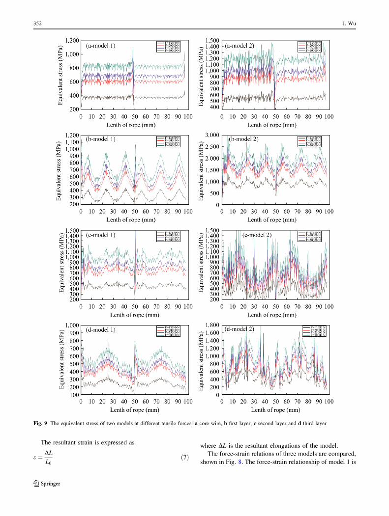
Fig. 9 The equivalent stress of two models at different tensile forces: a core wire, b first layer, c second layer and d third layer
352 J. Wu
123
similar with that of model 3. The first twisting manner of
model 1 is contrary to the twisting manner of model 3 and
the other twisting manner of two models are identical. The
third twisting manner of model 2 is contrary to the twisting
manner of model 1 and the other twisting manner of two
models are the same. For the resultant elongations and the
strain of model 2 are higher than that of other models, it
indicates that the relation of twisting manner between first
layer and second layer has little influence on strain and
stress and those between second layer and third layer has
influence on the response of the rope under tension.
4.3 Comparison of the equivalent stresses for different
models
For the resultant elongations and the strain of model 1 are
similar with those of model 3, only the equivalent stresses
of the four wires in model 1 and model 2 at the X positive
direction (see Fig. 3a, b) along Z direction are studied.
The equivalent stresses of layers in two models at tensile
forces: F1 = 13,680 N, F2 = 20,000 N, F3 = 25,000 N
and F4 = 30,000 N are shown in Fig. 9 and Table 6.
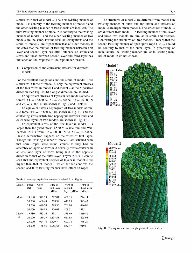
The equivalent stress nephogram of two models at ten-
sile force (F1 = 13,680 N) are shown in Fig. 10, and the
contacting stress distribution nephogram between inner and
outer wire layers of two models are shown in Fig. 11.
The equivalent stress of the first layer in model 2 is
larger than the yield stress 1,580 MPa (Beltran and Wil-
liamson 2011) from F2 = 20,000 N to F4 = 30,000 N.
Plastic deformation happens on the wires of first layer.
Though the twisting manner of model 2 are satisfied with
that spiral ropes were round strands as they had an
assembly of layers of wires laid helically over a center with
at least one layer of wires being laid in the opposite
direction to that of the outer layer (Feyrer 2007), it can be
seen that the equivalent stresses of layers in model 2 are
higher than that of model 1 which further confirms the
second and third twisting manner have effect on ropes.
The structures of model 2 are different from model 1 in
twisting manner of outer and the strain and stresses of
model 2 are higher than model 1. The structures of model 3
are different from model 1 in twisting manner of first layer
and these two models are similar in strain and stresses.
Contrasting the structures of three models, it means that the
second twisting manner of open spiral rope 1 9 37 should
be contrary to that of the outer layer. In processing of
manufacture the twisting manner similar to twisting man-
ner of model 2 do not choose.
Table 6 Average equivalent stresses obtained from Fig. 9
Model Force
(N)
Core
wire
Wire of
first layer
(MPa)
Wire of
second
layer (MPa)
Wire of
third layer
(MPa)
Model
1
13,680 372.59 322.01 460.35 244.14
20,000 600.48 518.99 641.93 393.47
25,000 680.74 588.36 701.09 446.06
30,000 816.89 706.03 809.31 535
Model
2
13,680 533.16 891 379.69 419.41
20,000 859.27 1,437.55 611.93 675.95
25,000 974.13 1,629.7 693.74 766.29
30,000 1,168.95 1,955.64 832.47 919.5Fig. 10 The equivalent stress nephogram of two models
The finite element modeling of spiral ropes 353
123

5 Conclusions
In order to simulate the complex geometry of open spiral
ropes by finite element analysis, the geometric parametric
equations were established and implemented in PRO/
ENGINEER software for the geometric models. The
methodology of their implementation and the approach for
creation of the geometric model for the open spiral ropes
were demonstrated. Three models had been established in
order to predict the behaviors of the models under different
tensile loads by ANSYS/Workbench.
The finite element models of spiral ropes with compli-
cated geometry and contact conditions had been developed
in this study. The normal stresses and force-strain rela-
tionship of the studied ropes obtained by the present finite
element analysis were compared with those obtained the-
oretically and experimentally. The present FE model was
proved to be accurate sufficiently as compared with
theoretical and experimental result, which can be utilized
to optimize key geometric parameter-twisting manner.
Further development is ongoing to analyze the equiva-
lent stresses which was induced by the twisting manner of
cables. The twisting manner in each layer was important to
ropes and the twisting manner of open spiral ropes with
three layers should not choose the twisting manner of
model 2. The outer twisting manner should be contrary to
that of the second layer, no matter what is the first twisting
manner of wires.
Acknowledgments This study is funded by International S&T
Cooperation Program of China (2011DFA72120) and NSFC (No.
51205272).
Open Access This article is distributed under the terms of the
Creative Commons Attribution License which permits any use, dis-
tribution, and reproduction in any medium, provided the original
author(s) and the source are credited.
References
Argatov I (2011) Response of a wire rope strand to axial and torsional
loads: asymptotic modeling of the effect of inter wire contact
deformations. Int J Solids Struct 48(10):1413–1423
Beltra’n JF, Vargas D (2012) Effect of broken rope components
distribution throughout rope cross-section on polyester rope
response: numerical approach. Int J Mech Sci 64(1):32–46
Beltran JF, Williamson EB (2011) Numerical procedure for the
analysis of damaged polyester ropes. Eng Struct 33(5):1698–1709
Bradon JE, Chaplin CR, Ermolaeva NS (2007) Modeling the cabling
of rope systems. Eng Fail Anal 14(5):920–934
Feyrer K (2007) Wire ropes, tension, endurance, reliability. Springer,
Berlin
Ghoreishi SR, Cartraud P, Davies P, Messager T (2007a) Analytical
modeling of synthetic fiber ropes subjected to axial loads. Part I:
a new continuum model for multilayered fibrous structures. Int J
Solids Struct 44(9):2924–2942
Ghoreishi SR, Cartraud P, Davies P, Messager T (2007b) Patrice
analytical modeling of synthetic fiber ropes. Part II: a linear
elastic model for 1 ? 6 fibrous structures. Int J Solids Struct
44(9):2943–2960
Jiang WG (2012) A concise finite element model for pure bending
analysis of simple wire strand. Int J Mech Sci 54(1):69–73
Jiang WG, Henshall JL, Walton JM (2000) A concise finite element
model for three-layered straight wire rope strand. Int J Mech Sci
42(1):63–86
Jiang WG, Warby MK, Henshall JL (2008) Statically indeterminate
contacts in axially loaded wire strand. Eur J Mech A Solids
27(1):69–78
Judge R, Yang Z, Jones SW, Beattie G (2012) Full 3D finite element
modeling of spiral strand cables. Constr Build Mater 35:452–459
Ma J, Ge SR, Zhang DK (2008) Distribution of wire deformation
within strands of wire rope. J China Univ Min Technol
18(3):475–478
Ma J, Ge SR, Zhang DK (2009) Load distribution on the unit of the
wire rope strand. J Med Eng Technol 45(4):259–264
Nakai M, Sato S, Aida T, Tomioka H (1975) On the creep and the
relaxation of spiral ropes. Bull JSME 18(125):1308–1314
Nawrocki A, Labrosse M (2000) A finite element model for simple
straight wire rope strands. Comput Struct 77(4):345–359
Fig. 11 The contacting stress distribution nephogram between inner
and outer wire layers of two models
354 J. Wu
123

Paczelt I, Belezna R (2011) Nonlinear contact-theory for analysis of
wire rope strand using high-order approximation in the FEM.
Comput Struct 89(11–12):1004–1025
Prawoto Y, Mazlan RB (2012) Wire ropes: computational, mechan-
ical, and metallurgical properties under tension loading. Comput
Mater Sci 56:174–178
Stanova E, Fedorko G, Fabian M, Kmet S (2011a) Computer
modeling of wire strands and ropes Part I: theory and computer
implementation. Adv Eng Softw 42:305–315
Stanova E, Fedorko G, Fabianc M, Kmet S (2011b) Computer
modeling of wire strands and ropes part II: finite element-based
applications. Adv Eng Softw 42:322–331
Usabiaga H, Pagalday JM (2008) Analytical procedure for modeling
recursively and wire by wire stranded ropes subjected to traction
and torsion loads. Int J Solids Struct 45(21):5503–5520
Wang DG, Zhang DK, Zhang ZF, Ge SR (2012) Effect of various
kinematic parameters of mine hoist on fretting parameters of
hoisting rope and a new fretting fatigue test apparatus of steel
wires. Eng Fail Anal 22:92–112
Wang DG, Zhang DK, Wang SQ, Ge SR (2013) A finite element
analysis of hoisting rope and fretting wear evolution and fatigue
life estimation of steel wires. Eng Fail Anal 27:173–193
The finite element modeling of spiral ropes 355
123