Embed Size (px)
Citation preview
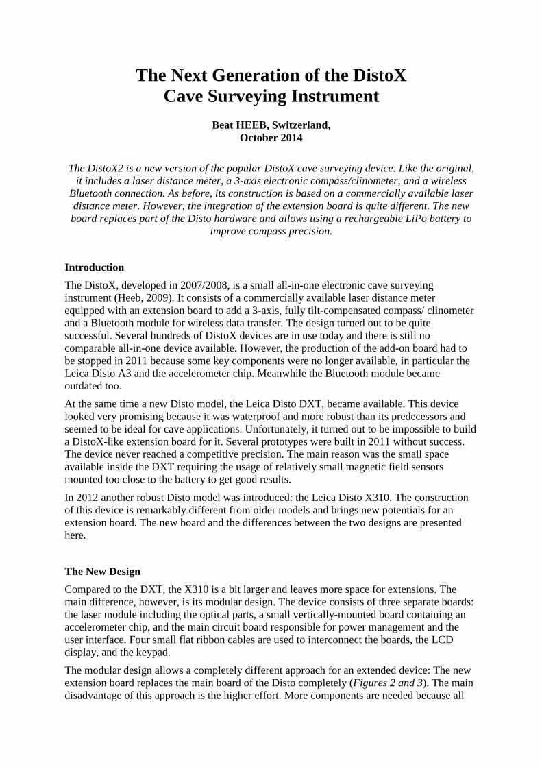
The Next Generation of the DistoX Cave Surveying Instrument
Beat HEEB, Switzerland,
October 2014
The DistoX2 is a new version of the popular DistoX cave surveying device. Like the original, it includes a laser distance meter, a 3-axis electronic compass/clinometer, and a wireless
Bluetooth connection. As before, its construction is based on a commercially available laser distance meter. However, the integration of the extension board is quite different. The new board replaces part of the Disto hardware and allows using a rechargeable LiPo battery to
improve compass precision.
Introduction
The DistoX, developed in 2007/2008, is a small all-in-one electronic cave surveying instrument (Heeb, 2009). It consists of a commercially available laser distance meter equipped with an extension board to add a 3-axis, fully tilt-compensated compass/ clinometer and a Bluetooth module for wireless data transfer. The design turned out to be quite successful. Several hundreds of DistoX devices are in use today and there is still no comparable all-in-one device available. However, the production of the add-on board had to be stopped in 2011 because some key components were no longer available, in particular the Leica Disto A3 and the accelerometer chip. Meanwhile the Bluetooth module became outdated too.
At the same time a new Disto model, the Leica Disto DXT, became available. This device looked very promising because it was waterproof and more robust than its predecessors and seemed to be ideal for cave applications. Unfortunately, it turned out to be impossible to build a DistoX-like extension board for it. Several prototypes were built in 2011 without success. The device never reached a competitive precision. The main reason was the small space available inside the DXT requiring the usage of relatively small magnetic field sensors mounted too close to the battery to get good results.
In 2012 another robust Disto model was introduced: the Leica Disto X310. The construction of this device is remarkably different from older models and brings new potentials for an extension board. The new board and the differences between the two designs are presented here.
The New Design
Compared to the DXT, the X310 is a bit larger and leaves more space for extensions. The main difference, however, is its modular design. The device consists of three separate boards: the laser module including the optical parts, a small vertically-mounted board containing an accelerometer chip, and the main circuit board responsible for power management and the user interface. Four small flat ribbon cables are used to interconnect the boards, the LCD display, and the keypad.
The modular design allows a completely different approach for an extended device: The new extension board replaces the main board of the Disto completely (Figures 2 and 3). The main disadvantage of this approach is the higher effort. More components are needed because all
functions of the original main board must be implemented, including power management, display illumination, and beeper. More work is also needed on the software side as the whole functionality and the user interface of the Disto must be re-implemented.
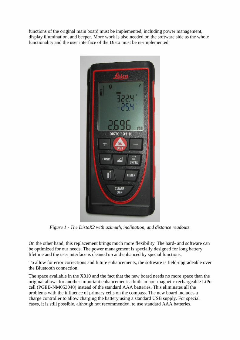
Figure 1 - The DistoX2 with azimuth, inclination, and distance readouts.
On the other hand, this replacement brings much more flexibility. The hard- and software can be optimized for our needs. The power management is specially designed for long battery lifetime and the user interface is cleaned up and enhanced by special functions.
To allow for error corrections and future enhancements, the software is field-upgradeable over the Bluetooth connection.
The space available in the X310 and the fact that the new board needs no more space than the original allows for another important enhancement: a built-in non-magnetic rechargeable LiPo cell (PGEB-NM053040) instead of the standard AAA batteries. This eliminates all the problems with the influence of primary cells on the compass. The new board includes a charge controller to allow charging the battery using a standard USB supply. For special cases, it is still possible, although not recommended, to use standard AAA batteries.
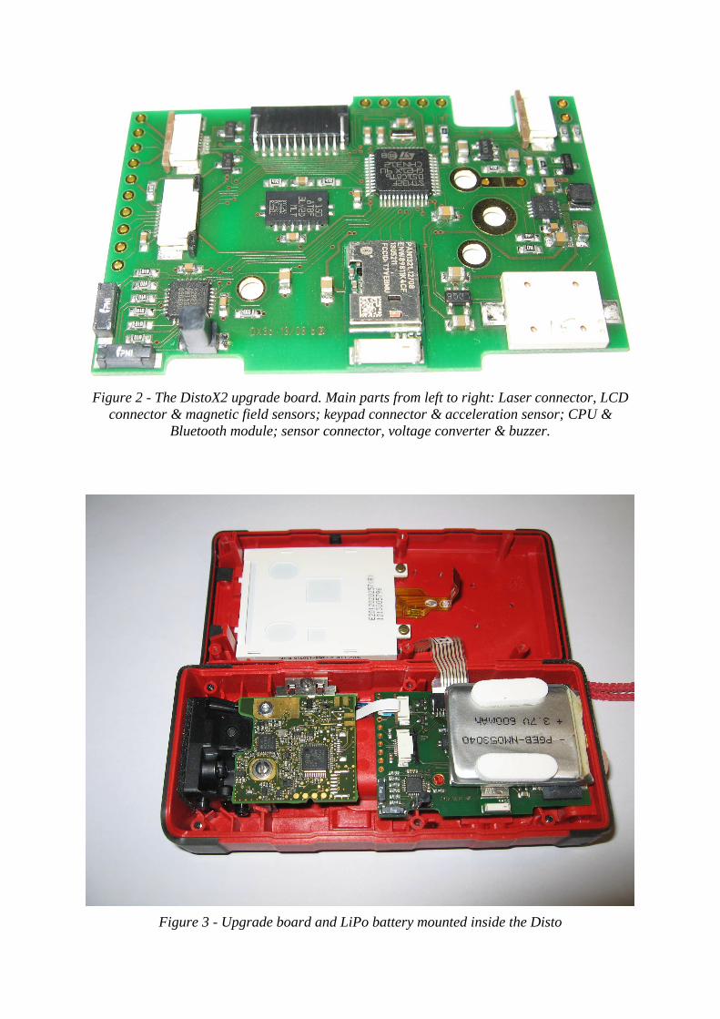
Figure 2 - The DistoX2 upgrade board. Main parts from left to right: Laser connector, LCD
connector & magnetic field sensors; keypad connector & acceleration sensor; CPU & Bluetooth module; sensor connector, voltage converter & buzzer.
Figure 3 - Upgrade board and LiPo battery mounted inside the Disto
Circuit Description
The main part of the circuit is an ARM Cortex M0 microcontroller (STM32F051C8). This is a low cost, low current 32 bit CPU with much more performance than the 8 bit PIC used in the DistoX1. It contains enough memory (8k RAM, 64k flash) to store every-thing including measured data and user options in the internal flash. There is still a lot of space available for the addition of new functions. Several serial, SPI, and I2C ports are used to communicate with the other parts. A cheap 8MHz ceramic resonator is used to provide the clock precision necessary to drive the serial ports.
The Bluetooth module used is a Panasonic PAN1321. The National module used in the DistoX1 is no longer available. Users reported a slightly better performance compared to the old module. Two dedicated pins are used to force the module into sleep mode and to wake it up. This saves a lot of power when the device is disconnected or connected in Sniff (power save) mode.
The magnetometer consists of the same magneto-inductive sensors used in the DistoX1. As before, a control chip is needed to readout the sensors. The actual version from the sensor manufacturer (PNI ‘MagIc’) allows somewhat higher performance and easier access from the controller.
Inclination is measured by the vertically-mounted acceleration sensor present in the X310. On the new board; however, it is complemented by a second, horizontally-mounted sensor (LIS3LV02) to provide full 3-axis measurements without making use of the less precise Z (vertical) directions. For the most critical X (forward) direction, the average of both sensors is used.
One of the critical parts of the circuit is the power management. Two stable voltages are needed to drive all the parts. 3.8V is required to power the laser board, the display illumination LED, and the Bluetooth module which includes its own power management. 3.3V is used for the CPU, the sensors, and the digital signals.
To support the usage of primary batteries as well as LiPo cells, an input voltage range of at least 2V to 4.2V must be supported. A TPS61200 voltage converter is used to convert this broad range to a constant 3.8V. The chip includes a switching step-up converter for low input voltages and a linear down converter for the just slightly higher upper voltages. A simple linear converter (LP3985) is used to generate 3.3V from 3.8V.
The TPS61200 is also used to switch power on and off. This is somewhat tricky because power is switched on by the DIST button when the CPU is not powered at all. Then the CPU takes over and assures power remains on until switched off by software. In addition, the same button must be readable by software because of its dual role (power on and distance).
A bipolar transistor is used to enable the voltage converter either by the button or by the connected CPU pin. To read the button state by software, the CPU pin is temporarily released and used as an input. The capacitor C12 at the enable input assures the converter does not switch off in this time. The resistor pair R14/R15 works as a pull-down for the enable input and as a voltage divider to measure the battery voltage using an A/D input of the CPU. Its placement after T3 ensures it does not draw any power when the device is switched off.
Transistors T1 and T2 are power switches for the display illumination LED and the LCD module. T1 can be driven by a PWM output to implement arbitrary illumination levels.
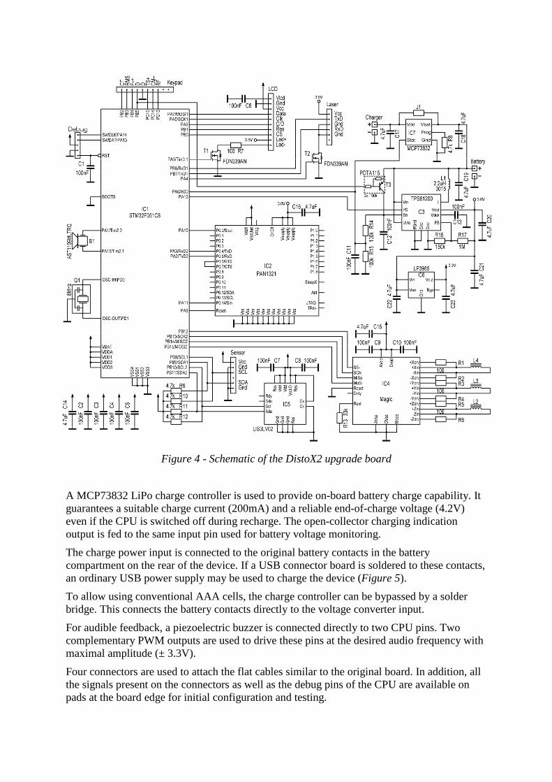
Figure 4 - Schematic of the DistoX2 upgrade board
A MCP73832 LiPo charge controller is used to provide on-board battery charge capability. It guarantees a suitable charge current (200mA) and a reliable end-of-charge voltage (4.2V) even if the CPU is switched off during recharge. The open-collector charging indication output is fed to the same input pin used for battery voltage monitoring.
The charge power input is connected to the original battery contacts in the battery compartment on the rear of the device. If a USB connector board is soldered to these contacts, an ordinary USB power supply may be used to charge the device (Figure 5).
To allow using conventional AAA cells, the charge controller can be bypassed by a solder bridge. This connects the battery contacts directly to the voltage converter input.
For audible feedback, a piezoelectric buzzer is connected directly to two CPU pins. Two complementary PWM outputs are used to drive these pins at the desired audio frequency with maximal amplitude (± 3.3V).
Four connectors are used to attach the flat cables similar to the original board. In addition, all the signals present on the connectors as well as the debug pins of the CPU are available on pads at the board edge for initial configuration and testing.
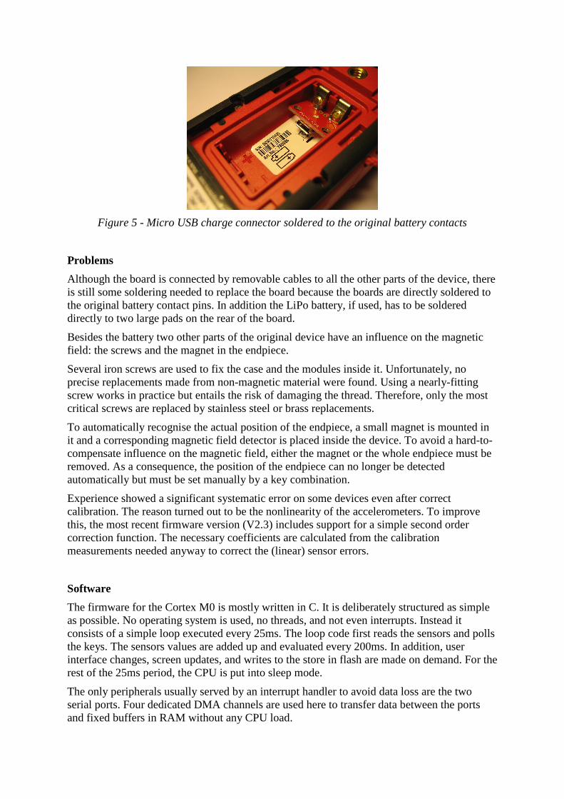
Figure 5 - Micro USB charge connector soldered to the original battery contacts
Problems
Although the board is connected by removable cables to all the other parts of the device, there is still some soldering needed to replace the board because the boards are directly soldered to the original battery contact pins. In addition the LiPo battery, if used, has to be soldered directly to two large pads on the rear of the board.
Besides the battery two other parts of the original device have an influence on the magnetic field: the screws and the magnet in the endpiece.
Several iron screws are used to fix the case and the modules inside it. Unfortunately, no precise replacements made from non-magnetic material were found. Using a nearly-fitting screw works in practice but entails the risk of damaging the thread. Therefore, only the most critical screws are replaced by stainless steel or brass replacements.
To automatically recognise the actual position of the endpiece, a small magnet is mounted in it and a corresponding magnetic field detector is placed inside the device. To avoid a hard-to-compensate influence on the magnetic field, either the magnet or the whole endpiece must be removed. As a consequence, the position of the endpiece can no longer be detected automatically but must be set manually by a key combination.
Experience showed a significant systematic error on some devices even after correct calibration. The reason turned out to be the nonlinearity of the accelerometers. To improve this, the most recent firmware version (V2.3) includes support for a simple second order correction function. The necessary coefficients are calculated from the calibration measurements needed anyway to correct the (linear) sensor errors.
Software
The firmware for the Cortex M0 is mostly written in C. It is deliberately structured as simple as possible. No operating system is used, no threads, and not even interrupts. Instead it consists of a simple loop executed every 25ms. The loop code first reads the sensors and polls the keys. The sensors values are added up and evaluated every 200ms. In addition, user interface changes, screen updates, and writes to the store in flash are made on demand. For the rest of the 25ms period, the CPU is put into sleep mode.
The only peripherals usually served by an interrupt handler to avoid data loss are the two serial ports. Four dedicated DMA channels are used here to transfer data between the ports and fixed buffers in RAM without any CPU load.
The user interface is designed to be as close as possible to the original X310. However, many functions not needed for surveying like Min, Max, Add, and Subtract were removed. In exchange, some new features are added. The SMART key is used to get additional information about the actual measurement. The FUNC key shows a sequence of information screens with information like battery voltage, versions, level of the display illumination, etc.
The first 2k of the flash is reserved for the Bootloader, a small self-contained program used to read or write the rest of the flash over the Bluetooth connection. It is started by a special key combination during power up. It is particularly useful for firmware updates.
Bluetooth Connection
For backward compatibility, the protocol used to communicate with a connected PDA or tablet is essentially the same as before. However, new packets are added, containing additional data (roll and dip angle, strength of magnetic and gravity field) useful for quality checking and post processing of calibration errors. They are currently ignored by the connected PDA. The device is compatible with PocketTopo (Heeb, 2008), Auriga (Le Blanc, 2004), and TopoDroid (Corvi). An Android version of PocketTopo is under construction.
Standard Bluetooth is used in place of the increasingly popular Bluetooth Low Energy (Bluetooth SIG, 2010) to allow using old devices not supporting Bluetooth 4.0.
Conclusions and Outlook
After a long time of uncertainty whether a new DistoX design is feasible at all, a new solution was finally found. Over 500 devices have been successfully constructed so far. Using AAA batteries, the performance is slightly worse compared to the old device because the magnetic sensor could not be separated equally well from the batteries. However, with the LiPo battery and, if necessary, the non-linearity correction, the performance and the long-term stability of the compass is even better than before.
Two firmware updates with corrections and extensions have been released so far. More will follow with new features. Even complex enhancements like on-device evaluation of the calibration measurements seem possible.
For further information about the DistoX2, PocketTopo, and the availability of extension boards, refer to the project’s web-page: http://paperless.bheeb.ch.The user manuals and the PocketTopo application are available from: http://paperless.bheeb.ch/download.html.
References
Bluetooth SIG, Bluetooth Specification 4.0, Volume 5, 30 June 2010; http://www.bluetooth.com.
Corvi, Marco, TopoDroid; http://code.google.com/p/topolinux/wiki/TopoDroid; https://play.google.com/store/apps/details?id=com.topodroid.DistoX.
Heeb, Beat (2009), An All-In-One Electronic Cave Surveying Device; CREG Journal 72: p. 8-10; BCRA Cave Radio and Electronics Group;
Heeb, Beat (2008), Paperless Caving – An Electronic Cave Surveying System; Proc. of the IV European Speleological Congress 2008, p. 130 – 133; http://paperless.bheeb.ch.
Le Blanc, Luc (2004), Auriga, or Trading your Survey Notebook for a PDA; Compass Points 32: p. 8-11; BCRA Cave Surveying Group; http://www.speleo.qc.ca/auriga.
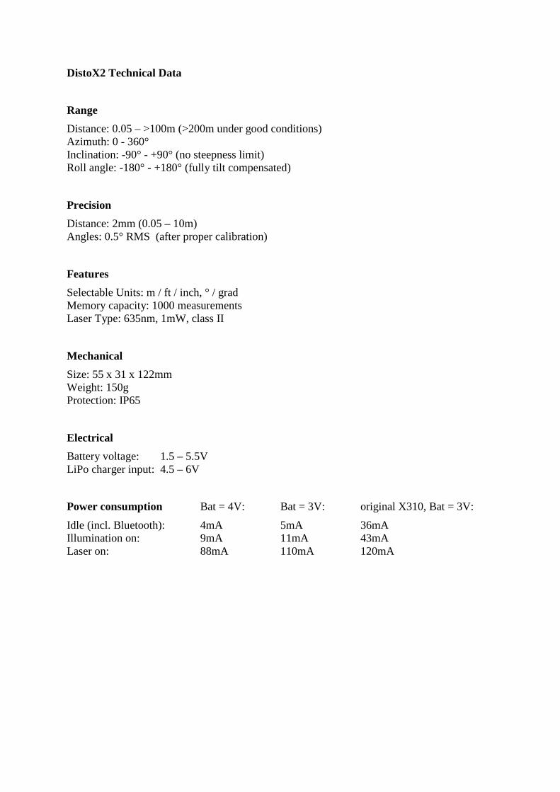
DistoX2 Technical Data
Range
Distance: 0.05 – >100m (>200m under good conditions) Azimuth: 0 - 360° Inclination: -90° - +90° (no steepness limit) Roll angle: -180° - +180° (fully tilt compensated)
Precision
Distance: 2mm (0.05 – 10m) Angles: 0.5° RMS (after proper calibration)
Features
Selectable Units: m / ft / inch, ° / grad Memory capacity: 1000 measurements Laser Type: 635nm, 1mW, class II
Mechanical
Size: 55 x 31 x 122mm Weight: 150g Protection: IP65
Electrical
Battery voltage: 1.5 – 5.5V LiPo charger input: 4.5 – 6V
Power consumption Bat = 4V: Bat = 3V: original X310, Bat = 3V:
Idle (incl. Bluetooth): 4mA 5mA 36mA Illumination on: 9mA 11mA 43mA Laser on: 88mA 110mA 120mA