Embed Size (px)
Citation preview

the newstandard in H e a t E x c h a n g e r s
Storage, Installation, Operation and Maintenance
Heat Transfer

ITT Heat Transfer heat exchangers are protect-ed against the elements during shipment. If they cannot be installed and put into operation immediately upon receipt at the jobsite, certain precautions are necessary to prevent deterioration during storage. Responsibility for integrity of the heat exchangers must be assumed by the user. ITT Heat Transfer will not be responsible for damage, corrosion or other deterioration of heat exchanger equipment during transit and storage.
Good storage practices are important, considering the high costs of repair or replacement, and the possible delays for items which require long lead times for manufacture. The following suggested practices are provided solely as a convenience to the user, who shall make his own decision on whether to use all or any of them.
1 On receipt of the heat exchanger, in spect for shipping damage to all protective covers. If damage is evident, inspect for possible contamination and replace pro-tective covers as required. If damage is extensive, notify the carrier immediately.
2 If the heat exchanger is not to be placed in immediate service, take precautions to prevent rusting or contamination.
3 Heat exchangers for oil service, made of ferrous materials, may be pressure-tested with oil at the fac-tory. However, the residual oil coating
on the inside surfaces of the exchanger does not preclude the possibility of rust formation. Upon receipt, fill these exchangers with appropriate oil or coat them with a corrosion prevention com-pound for storage. These heat exchangers have a large warning decal, indicating that they should be protected with oil.
4 The choice of preservation of interior surfaces during storage for other service applications depends upon your system requirements and economics. Only when included in the original purchase order specifications will specific preservation be incorporated prior to shipment from the factory.
5 Remove any accumulations of dirt, water, ice or snow and wipe dry before moving exchangers into indoor storage. If unit was not filled with oil or other preservative, open drain plugs to remove any accumulated moisture, then reseal. Accumulation of moisture usually indicates rusting has already started and remedial action should be taken.
6 Store under cover in a heated area, if possible. The ideal storage environment for heat exchangers and accessories is indoors, above grade, in a dry, low-humidity atmosphere which is sealed to prevent entry of blowing dust, rain or snow. Maintain tempera-
tures between 70°F and 105°F (wide temperature swings may cause conden-sation and “sweating” of steel parts). Cover windows to prevent temperature variations caused by sunlight. Provide thermometers and humidity indicators at several points, and maintain atmosphere at 40% relative humidity or lower.
7 In tropical climates, it may be necessary to use trays of renewable dessicant (such as silica gel), or portable dehumidifiers, to remove moisture from the air in the storage enclosure. Thermostatically controlled portable heaters (vented to out-doors) may be required to maintain even air temperatures inside the enclosure.
8 Inspect heat exchangers and acces-sories frequently while they are in storage. Start a log to record results of inspections and maintenance performed while units are in storage. A typical log entry should include, for each component, at least the following:
a. Date b. Inspector’s name c. Identification of unit or item d. Location e. Condition of paint or coating f. Condition of interior g. Is free moisture present? h. Has dirt accumulated? i. Corrective steps taken
Storage
This bulletin has been prepared as an aid and guide to maintenance personnel. Read it thoroughly prior to installation of any ITT Heat Transfer heat exchanger in order to ensure correct installation and best performance.
note: Before placing this equipment in operation, environment and service conditions should be checked for compat ibility with materials of construction. contact your nearest Itt Heat transfer representative if you are not sure what the actual materials of construction are.
Successful performance of heat transfer equipment, length of service and freedom from operating difficulties are largely dependent upon:
1. Proper thermal design.2. Proper physical design.3. Storage practice prior to installation.4. Manner of installation, including design
of foundation and piping.5. The method of operation.6. The thoroughness and frequency
of cleaning.7. The materials, workmanship, and tools
used in maintenance and making repairs and replacements.
Failure to perform properly may be due to one or more of the following:1. Exchanger being dirty.2. Failure to remove preservation
materials after storage.3. Operating conditions being different
than design conditions.4. Air or gas binding.5. Incorrect piping connections.6. Excessive clearances between
internal parts due to corrosion.7. Improper application.
2

If paint deterioration begins, as evidenced by discoloration or light rusting, consider touch-up or repainting. If the unit is painted with our standard shop enamel, areas of light rust may be wire brushed and touched-up with any good quality air-drying synthetic enamel. Units painted with special paints (when specified on customers’ orders) may require special techniques for touch-up or repair. Obtain specific information from the paint manufacturer. Painted steel units should never be permitted to rust or dete riorate to a point where their strength will be impaired. But a light surface rusting, on steel units which will be re-painted after installation, will not generally cause any harm. (See Items 3 and 4 for internal surface preservation.)
If the internal preservation (Items 3 and 4) appears inadequate during storage, consider additional corrosion prevention measures and more frequent inspections. Interiors coated with rust preventive should be restored to good condition and re-coated promptly if signs of rust occur.
1 On removable bundle heat exchangers, provide sufficient clearance at the station-ary end to permit the removal of the tube bundle from the shell. On the floating head end, provide space to permit removal of the shell cover and floating head cover.
2 On fixed bundle heat exchangers, provide sufficient clearance at one end to permit removal and replacement of tubes and at the other end provide sufficient clearance to permit tube rolling.
3 Provide valves and bypasses in the piping system so that both the shell side and tube side may be bypassed to permit isolation of the heat exchanger for inspection, cleaning and repairs.
4 Provide convenient means for frequent cleaning as suggested under maintenance.
5 Provide thermometer wells and pressure gauge pipe taps in all piping to and from the heat exchanger, located as close to the heat exchanger as possible.
6 Provide necessary air vent valves for the heat exchanger so that it can be purged to prevent or relieve vapor or gas binding on both the tube side and shell side.
7 Provide adequate supports for mounting the heat exchanger so that it will not settle and cause piping strains. Foundation bolts should be set accu-rately. In concrete footings, pipe sleeves at least one pipe size larger than the bolt diameter slipped over the bolt and cast in place are best for this purpose as they allow the bolt centers to be adjusted after the foundation has set.
8 Install proper liquid level controls and relief valves and liquid level and temperature alarms, etc.
9 Install gauge glasses or liquid level alarms in all vapor or gas spaces to indicate any failure occurring in the condensate drain system and to prevent flooding of the heat exchanger.
10 Install a surge drum upstream from the heat exchanger to guard against pulsation of fluids caused by pumps, compressors or other equipment.
11Do not pipe drain connections to a common closed manifold; it makes it more difficult to determine that the exchanger has been thoroughly drained.
Installation Planning
cautIon:Provide fire extinguishers, fire alarms or telephone to protect building and equip ment against fire damage. Be sure that the building and storage practices meet all local, state, and federal fire and safety codes!
109
3

1 If you have maintained the heat exchanger in storage, thoroughly inspect it prior to installation. Make sure it is thoroughly cleaned to remove all preserva-tion materials unless stored full of the same oil being used in the system, or the coating is soluble in the lubricating system oil.
If the exchanger was oil-tested by ITT Heat Transfer and your purchase order did not specify otherwise, the oil used was Tectyl 754, a light-bodied oil which is soluble in most lubricating oils. Where special preservations were applied, you should consult the preservative manufacturer’s product information data for removal instructions.
2 If the heat exchanger is not being stored, inspect for shipping damage to all protective covers upon receipt at the jobsite. If damage is evident, inspect for possible contamination and replace protective covers as required. If damage is extensive, notify the carrier immediately.
3 When installing, set heat exchanger level and square so that pipe connections can be made without forcing.
4 Before piping up, inspect all openings in the heat exchanger for foreign material. Remove all wooden plugs, bags of dessicant and shipping covers imme-diately prior to installing. Do not expose internal passages of the heat exchanger to the atmosphere since moisture or harmful contaminants may enter the unit and cause severe damage to the system due to freezing and/or corrosion.
5 After piping is complete, if support cradles or feet are fixed to the heat exchanger, loosen foundation bolts at one end of the exchanger to allow free movement. Oversized holes in support cradles or feet are provided for this purpose.
6 If heat exchanger shell is equipped with a bellows-type expansion joint, remove shipping supports per instructions.
1 Be sure entire system is clean before starting operation to prevent plugging of tubes or shell side passages with refuse. The use of strainers or settling tanks in pipelines leading to the heat exchanger is recommended.
2 Open vent connections before starting up.
3 Start operating gradually. See Table 1 for suggested start-up and shut-down procedures for most applications. If in doubt, consult the nearest ITT Heat Transfer representative for specific instructions.
4 After the system is completely filled with the operating fluids and all air has been vented, close all manual vent connections.
5 Re-tighten bolting on all gasketed or packed joints after the heat exchanger has reached operating temperatures to prevent leaks and gasket failures. Standard published torque values do not apply to packed end joints.
6 Do not operate the heat exchanger under pressure and temperature conditions in excess of those specified on the nameplate.
7 To guard against water hammer, drain condensate from steam heat exchangers and similar apparatus both when starting up and shutting down.
8 Drain all fluids when shutting down to eliminate possible freezing and corroding.
Installation at Jobsite
Operation
4
cautIon: Dress properly for the job. You may need any number of special items — safety hat, safety shoes, goggles, heavy gloves, ear protective devices, etc., for your own protection. Find out what items are required and wear them.
cautIon: A heat exchanger is a pressure vessel designed for operation at certain specific limits of pressure and temperature. The cooling or process system, which includes the heat exchanger, must be safeguarded with safety valves and controls so that these heat exchanger design conditions are not exceeded. All operating personnel should be made aware of these specific design pressures and temperatures.
cautIon: Many heat exchangers circulate fluids which are irritating or dangerous to the human system. These fluids could cause problems if bolted or threaded joints are not maintained in a leaktight condition at operating pressures, temperatures and noflow, ambient conditions.
If fluids are not irritating or dangerous, a leak will at least cause a slippery situation on the floor below.
Because one fluid in the heat exchanger is at higher temperatures, any leaks might cause burns.
9 In all installations there should be no pul-sation of fluids, since this causes vibration and will result in reduced operating life.
10 Under no circumstances is the heat exchanger to be operated at a flowrate greater than that shown on the design specifications. Excessive flows can cause vibration and severely damage the heat exchanger tube bundle.
11 Heat exchangers that are out of service for extended periods of time should be protected against corrosion as described in the storage requirements for new heat exchangers.
Heat exchangers that are out of service for short periods and use water as the flowing medium should be thoroughly drained and blown dry with warm air,
if possible. If this is not practical, the water should be circulated through the heat exchanger on a daily basis to pre-vent stagnant water conditions that can ultimately precipitate corrosion.
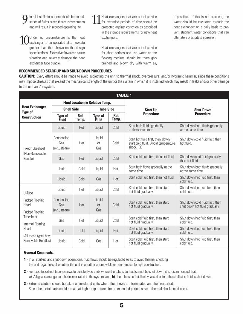
recoMMended Start-uP and SHut-doWn ProcedureScautIon: Every effort should be made to avoid subjecting the unit to thermal shock, overpressure, and/or hydraulic hammer, since these conditions may impose stresses that exceed the mechanical strength of the unit or the system in which it is installed which may result in leaks and/or other damage to the unit and/or system.
fluid location & relative temp.
Start-upProcedure
Shut-downProcedure
Shell Side tube Side
type offluid
rel.temp.
type offluid
rel.temp.
Start both fluids gradually Shut down both fluids graduallyat the same time. at the same time.
Start hot fluid first, then slowly Shut down cold fluid first, thenstart cold fluid. Avoid temperature hot fluid.shock. (1)
Start cold fluid first, then hot fluid. Shut down cold fluid gradually, then hot fluid.
Start both flows gradually at the Shut down both fluids graduallysame time. at the same time.
Start cold fluid first, then hot fluid. Shut down hot fluid first, then cold fluid.
Start cold fluid first, then start Shut down hot fluid first, thenhot fluid gradually. cold fluid.
Start cold fluid first, then start Shut down cold fluid first, thenhot fluid gradually. shut down hot fluid gradually.
Start cold fluid first, then start Shut down hot fluid first, thenhot fluid gradually. cold fluid.
Start cold fluid first, then start Shut down hot fluid first, thenhot fluid gradually. cold fluid.
Start cold fluid first, then start Shut down hot fluid first, thenhot fluid gradually. cold fluid.
General comments:
1.) In all start-up and shut-down operations, fluid flows should be regulated so as to avoid thermal shocking the unit regardless of whether the unit is of either a removable or non-removable type construction.
2.) For fixed tubesheet (non-removable bundle) type units where the tube side fluid cannot be shut down, it is recommended that: a) A bypass arrangement be incorporated in the system; and, b) the tube side fluid be bypassed before the shell side fluid is shut down.
3.) Extreme caution should be taken on insulated units where fluid flows are terminated and then restarted. Since the metal parts could remain at high temperatures for an extended period, severe thermal shock could occur.
Fixed Tubesheet (Non-Removable Bundle)
U-Tube
Packed Floating Head
Packed Floating Tubesheet
Internal Floating Head
(All these types have Removable Bundles)
TABLE 1
Heat exchangertype ofconstruction
Liquid Hot Liquid Cold Condensing Liquid Gas Hot or Cold (e.g., steam) Gas
Gas Hot Liquid Cold
Liquid Cold Liquid Hot
Liquid Cold Gas Hot
Liquid Hot Liquid Cold
Condensing Liquid Gas Hot or Cold (e.g., steam) Gas
Gas Hot Liquid Cold
Liquid Cold Liquid Hot
Liquid Cold Gas Hot
5

1 Clean exchangers subject to fouling (scale, sludge deposits, etc.) periodi-cally, depending on specific conditions. A light sludge or scale coating on either side of the tube greatly reduces its effectiveness. A marked increase in pressure drop and/or reduction in performance usually indicates cleaning is necessary. Since the difficulty of cleaning increases rapidly as the scale thickens or deposits increase, the intervals between cleanings should not be excessive.
2 Neglecting to keep tubes clean may result in random tube plugging. Con sequent over heating or cooling of the plugged tubes, as compared to surrounding tubes, will cause physical damage and leaking tubes due to differ-ential thermal expansion of the metals.
3 To clean or inspect the inside of the tubes, remove only the necessary tube side channel covers or bonnets, depend-ing on type of exchanger construction.
4 If the heat exchanger is equipped with sacrificial anodes or plates, replace these as required.
5 To clean or inspect the outside of the tubes, it may be necessary to remove the tube bundle. (Fixed tubesheet exchanger bundles are non-removable).
6 When removing tube bundles from heat exchangers for inspection or cleaning, exercise care to see that they are not damaged by improper handling.
•Theweightofthetubebundleshould not be supported on individual tubes but should be carried by the tube sheets, support or baffle plates or on blocks contoured to the periphery of the tube bundles.
•Donothandle tubebundleswithhooksor other tools which might damage tubes. Move tube bundles on cradles or skids.
•To withdraw tube bundles, pass rods through two or more of the tubes and take the load on the floating tubesheet.
•Rodsshouldbethreadedatbothends, provided with nuts, and should pass through a steel bearing plate at each end of the bundle.
•Insertasoftwoodfillerboardbetween the bearing plate and tubesheet face to prevent damage to the tube ends.
•Screw forged steel eyebolts into both bearing plates for pulling and lifting.
•As an alternate to the rods, thread a steel cable through one tube and return through another tube.
•Ahardwoodspreaderblockmustbe inserted between the cable and each tubesheet to prevent damage to the tube ends.
7 If the heat exchanger has been in service for a considerable length of time without being removed, it may be necessary to use a jack on the floating tubesheet to break the bundle free.
•Use a good-sized steel bearing plate with a filler board between the tubesheet face and bearing plate to protect the tube ends.
8 Lift tube bundles horizontally by means of a cradle formed by bending a light-gauge plate or plates into a U-shape.Make attachments in the legs of the U for lifting.
9 Do not drag bundles, since baffles or support plates may become easily bent. Avoid any damage to baffles so that the heat exchanger will function properly.
10 Some suggested methods of cleaning either the shell side or tube side are listed below:
•Circulating hot wash oil or light distil-late through tube side or shell side will usually effectively remove sludge or similar soft deposits.
•Softsaltdepositsmaybewashedoutby circulating hot fresh water.
•Somecommercialcleaningcompounds such as “Oakite” or “Dowell” may be effective in removing more stubborn deposits. Use in accordance with the manufacturer’s instructions.
11 Some tubes have inserts or longitudinal fins and can be damaged by cleaning when mechanical means are employed. Clean these types of tubes chemically or consult the nearest ITT Heat Transfer rep-resentative for the recommended method of cleaning.
•Ifthescaleishardandtheabovemeth-ods are not effective, use a mechanical means. Neither the inside nor the out- side of the tube should be hammered with a metallic tool. If it is necessary to use scrapers, they should not be sharp enough to cut the metal of the tubes. Take extra care when employing scra- pers to prevent tube damage.
Do not attempt to clean tubes by blowing steam through individual tubes. This overheats the individual tube and results in severe expansion strains and leaking tube-to-tubesheet joints.
12 Table 2 shows safe loads for steel rods and eyebolts.
Maintenance
STEEL ROdS STEEL EyEBOLTS Tube Rod Safe Load Size Safe Load Size Size Per Rod
5/8” 3/8” 1,000 lbs. 3/4” 4,000 lbs. 3/4” 1/2” 2,000 lbs. 1” 6,000 lbs. 1” or 1-1/4” 10,000 lbs. larger 5/8” 3,000 lbs. 1 -1/2” 15,000 lbs.
taBle 26

13 To locate ruptured or corroded tubes or leaking joints between tubes and tubesheets, the following procedure is recommended:
•Removetubesidechannelcovers or bonnets.
•Pressurizetheshellsideoftheexchanger with a cold fluid, preferably water.
•Observetubejointsandtubeendsfor indication of test fluid leakage.
14 With certain styles of exchangers, it will be necessary to buy or make a test ring to seal off the space between the floating tubesheet and inside shell diameter to apply the test in paragraph 13. Consult your nearest ITT Heat Transfer sales representative for reference drawings showing installation of a test ring in your heat exchanger.
15 To tighten a leaking tube joint, use a suitable parallel roller tube expander.
•Donotrolltubesbeyondthebackface of the tubesheet. Maximum rolling depth should be tubesheet thickness minus 1/8”.
•Donotre-rolltubesthatarenotleaking since this needlessly thins the tube wall.
16 It is recommended that when a heat exchanger is dismantled, new gaskets be used in reassembly.
•Composition gaskets become brittleand dried out in service and do not provide an effective seal when reused.
•Metal or metal jacketed gaskets ininitial compression match the contact surfaces and tend to work-harden and cannot be recompressed on reuse.
17 Use of new bolting in conformance with dimension and ASTM specifications of the original design is recommended where frequent dismantling is encountered.
cautIon: Do not remove channel covers, shell covers, floating head covers or bonnets until all pressure in the heat exchanger has been relieved and both shell side and tube side are completely drained.
cautIon: Since many of the removable components of the heat exchanger, particularly in the larger sizes, are too heavy for people to handle, care must be used to take this weight with proper rigging to avoid injury. Wear hard hats and safety shoes as required.
cautIon: Do not thread rods or cables through tubes of a heat exchanger equipped with ITT Standard Amatran® tubes, or any with internal fins.
cautIon: When the heat exchanger is cleaned, it is important that full characteristics of the fouling material and the cleaning agent be known and care exercised in handling them according to instructions. Use eye protection to prevent damage to your eyes. Wear a respirator when required.
cautIon: Do not blow out heat exchangers with air when the normal process fluids or the cleaning fluids being handled are inflammable.
7
Warranty of Seller’S ProductS Except where a different express warranty has been issued with respect to a particular product, no war-ranty of any kind, express or implied, is extended by the seller to any person or persons other than its direct Buyers. To direct Buyers, the Seller warrants only that it will furnish by freight a replacement for, or at its option repair, any product of its manufacture or part or portion thereof, proved to its satisfaction to be defective in material or workmanship under normal use and service (i) within a period of six (6) months from date of shipment as to those parts which contain perishable elastomers or (ii) within one year from the date all other equipment or part thereof is first placed in use, or two years from the date of shipment, whichever shall be less.
The Seller shall have no responsibility for the perfor-mance of any product sold by it under conditions vary-ing materially from those under which such product is usually tested under existing industry standards, nor for any damage to the product from abrasion, erosion, corrosion, deterioration or the like due to abnormal temperatures or corrosive fluids or the influence of foreign matter or energy, or flow induced vibration caused by associated equipment or external influ-ences; nor for the design or operation of any system of which any such product may be made a part or for the suitability of any such product for any particular application. The Seller shall not be liable for any cost or expense, including, without limitation, labor expense, in connection with the removal or replace-ment of alleged defective equipment or any part or portion thereof nor for incidental or consequential damages of any kind, nor under any circumstances for any damage beyond the price of the goods sold.
Any freight allowance in connection with a replace-ment will be on the same terms as were applicable to the original sale, except that a replacement for a product or part or portion thereof which is proved to the Seller’s satisfaction to be defective in material or workmanship as provided herein above, will in any event be furnished with freight (but not local cart-age) allowed, within the country of origin, to the first destination. Any substitution of parts not of Seller’s manufacture or not authorized by Seller, or any modification, tampering, or manipulation of Seller’s product, shall void the warranty.
other Warranties — The foregoing warranty is in lieu of all other warranties of any kind, express or implied, and of all other obligations or liabilities, on the part of the Seller. The Seller neither assumes, nor does it authorize any other person to assume on its behalf, any other liability in connection with the sale of its products.
Seller expressly disclaims the implied warranties of merchantability and fitness for a particular purpose.
Goods of other Manufacturers — Goods of other manufacturers sold by the Seller are not warranted except by express warranties which may be issued in writing from time to time with respect to a par-ticular product or a particular sale; but the Seller will endeavor to secure for its direct Buyers the benefits of warranties extended by the manufacturers of such goods sold but not manufactured by the Seller.
Warranty
F o r m o r e i n f o r m a t i o n , p l e a s e c o n t a c t :
175 Standard Parkway • Cheektowaga, NY 14227800/447-7700 fax: 716/897-1777www.itt.com
Heat Transfer
Lit #104-17© 2007 ITT