Embed Size (px)
Citation preview
The new RS-35M, June, 2010 - Stu Martin, [email protected] This is a short note of thanks to you and your contributors for the top Web site supporting Astron’s RS-35M power supply. Seems I’ve acquired the most current model so I felt compelled to submit the changes I found. This unit was purchased through eBay for $155, Oct. 2009. Let me know if you need any additional photos. Sorry that I did not have time to lift the circuit board and inventory and match-up those components. And lastly, no modifications were performed on this unit. This supply is a clean production unit. Should any maintenance issues develop they will be reported.
Figure 1
Fig: 1: During the initial inspection I noticed this RS-35M is the latest in the series with illuminated meters and a removable power cable.
Figure 2
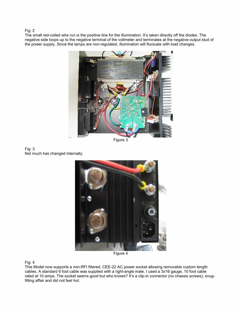
Fig: 2 The small red-coiled wire run is the positive line for the illumination. It’s taken directly off the diodes. The negative side loops up to the negative terminal of the voltmeter and terminates at the negative output stud of the power supply. Since the lamps are non-regulated, illumination will fluctuate with load changes.
Figure 3
Fig: 3 Not much has changed internally.
Figure 4
Fig: 4 This Model now supports a non-RFI filtered, CEE-22 AC power socket allowing removable custom length cables. A standard 6 foot cable was supplied with a right-angle mate. I used a 3x16 gauge, 10 foot cable rated at 10 amps. The socket seems good but who knows? It’s a clip-in connector (no chassis screws), snug-fitting affair and did not feel hot.
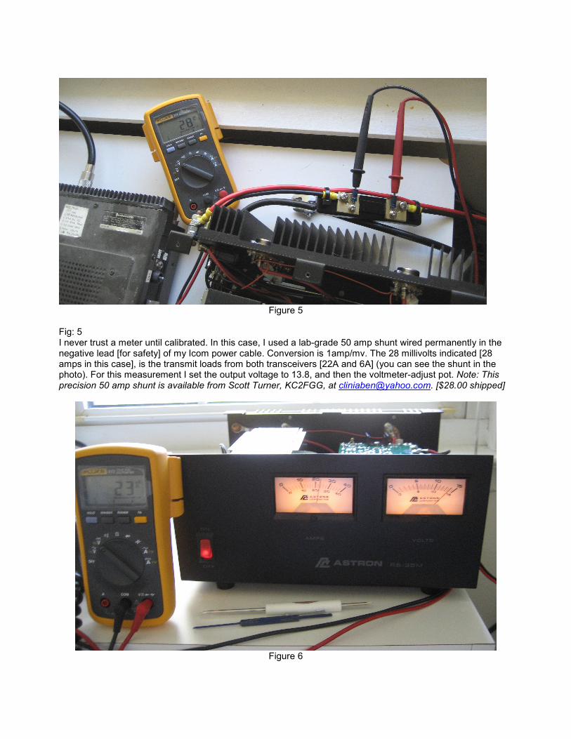
Figure 5
Fig: 5 I never trust a meter until calibrated. In this case, I used a lab-grade 50 amp shunt wired permanently in the negative lead [for safety] of my Icom power cable. Conversion is 1amp/mv. The 28 millivolts indicated [28 amps in this case], is the transmit loads from both transceivers [22A and 6A] (you can see the shunt in the photo). For this measurement I set the output voltage to 13.8, and then the voltmeter-adjust pot. Note: This precision 50 amp shunt is available from Scott Turner, KC2FGG, at [email protected]. [$28.00 shipped]
Figure 6
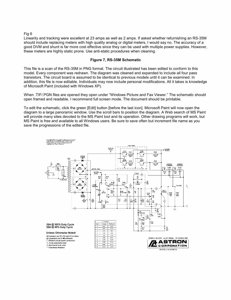
Fig 6 Linearity and tracking were excellent at 23 amps as well as 2 amps. If asked whether refurnishing an RS-35M should include replacing meters with high quality analog or digital meters, I would say no. The accuracy of a good DVM and shunt is far more cost effective since they can be used with multiple power supplies. However, these meters are highly static prone. Use anti-static procedures when cleaning.
Figure 7, RS-35M Schematic This file is a scan of the RS-35M in PNG format. The circuit illustrated has been edited to conform to this model. Every component was redrawn. The diagram was cleaned and expanded to include all four pass transistors. The circuit board is assumed to be identical to previous models until it can be examined. In addition, this file is now editable. Individuals may now include personal modifications. All it takes is knowledge of Microsoft Paint (included with Windows XP). When .TIF/.PGN files are opened they open under “Windows Picture and Fax Viewer.” The schematic should open framed and readable. I recommend full screen mode. The document should be printable. To edit the schematic, click the green [Edit] button [before the last icon]. Microsoft Paint will now open the diagram to a large panoramic window. Use the scroll bars to position the diagram. A Web search of MS Paint will provide many sites devoted to the MS Paint tool and its operation. Other drawing programs will work, but MS Paint is free and available to all Windows users. Be sure to save often but increment file name as you save the progressions of the edited file.