Embed Size (px)
Citation preview
33RD INTERNATIONAL COSMIC RAY CONFERENCE, RIO DE JANEIRO 2013THE ASTROPARTICLE PHYSICS CONFERENCE
The NectarCAM camera projectJ-F.GLICENSTEIN1, M.BARCELO11, J-A. BARRIO12 , O.BLANCH11 , J.BOIX11, J.BOLMONT4, C.BOUTONNET2
S.CAZAUX1, E.CHABANNE7, C.CHAMPION2, F.CHATEAU1 , S.COLONGES2 , P.CORONA4, S.COUTURIER5 ,B.COURTY2 , E.DELAGNES1, C.DELGADO10, J-P.ERNENWEIN6, S.FEGAN5, O.FERREIRA5, M.FESQUET1 ,G.FONTAINE5 , N.FOUQUE7 , F.HENAULT8 , D.GASCON13 , D.HERRANZ12 , R.HERMEL7 , D.HOFFMANN6 , J.HOULES6 ,S.KARKAR4 , B.KHELIFI5 , J.KNODLSEDER3 , G.MARTINEZ10 , K.LACOMBE3 , G.LAMANNA7 , T.LEFLOUR7 , R.LOPEZ-COTO11, F.LOUIS1 , A.MATHIEU5 , E.MOULIN1 , P.NAYMAN4 , F.NUNIO1, J-F. OLIVE3, J-L. PANAZOL7 , P-O.PETRUCCI8 , M.PUNCH2 , J.PRAST7 , P.RAMON3 , M.RIALLOT1 , M.RIBO13 , S.ROSIER-LEES7 , A.SANUY13 , J.SIERO13 ,J-P.TAVERNET4, L.A.TEJEDOR12, F.TOUSSENEL455 , G.VASILEIADIS9 , V.VOISIN4, V.WAEGEBERT3, C.ZURBACH9,FOR THE CTA CONSORTIUM.1 DSM/IRFU, CEA-Saclay, F91191 Gif-sur-Yvette, France2 APC, AstroParticule et Cosmologie, Universite Paris Diderot, CNRS/IN2P3, CEA/Irfu, Observatoire de Paris, Sorbonne Paris Cite, 10,rue Alice Domon et Leonie Duquet, 75205 Paris Cedex 13, France3 Institut de Recherche en Astrophysique et Planetologie, 9 av. colonel Roche, BP 44 346, 31028 Toulouse Cedex 4, France4 LPNHE, Universite Pierre et Marie Curie Paris 6, Universite Denis Diderot Paris 7, CNRS/IN2P3, 4 Place Jussieu, F-75252, ParisCedex 5, France5 Laboratoire Leprince-Ringuet, Ecole Polytechnique, CNRS/IN2P3, F-91128 Palaiseau, France6 Centre de Physique des Particules de Marseille, CNRS/IN2P3, 168 Avenue de Luminy, 13009 Marseille, France7 LAPP, Universite de Savoie, CNRS/IN2P3, 9 Chemin de Bellevue - BP 110, 74941 Annecy-le-Vieux Cedex, France8 UJF-Grenoble 1 CNRS/INSU, Institut de Planetologie et d’Astrophysique de Grenoble (IPAG) UMR 5274, Grenoble, F-38041, France9 Laboratoire Univers et Particules de Montpellier, Universite Montpellier 2, CNRS/IN2P3, CC 72, Place Eugene Bataillon, F-34095Montpellier Cedex 5, France10 CIEMAT, Avda. Complutense 22, 28040 Madrid, Spain11 Institut de Fisica d’Altes Energies (IFAE) Edifici Cn, Campus UAB, 08193 Bellaterra, Spain12 Grupo de Altas Energias, Universidad Complutense de Madrid, Av Complutenses, 28040 Madrid, Spain13 Departament d’Astronomia i Meteorologia (ICC-UB), Universitat de Barcelona, Marti i Franques, 1, 08028, Barcelona, Spain
Abstract: In the framework of the next generation of Cherenkov telescopes, the Cherenkov Telescope Array(CTA), NectarCAM is a camera designed for the medium size telescopes covering the central energy range of 100GeV to 30 TeV. NectarCAM will be finely pixelated (∼ 1800 pixels for a 8o field of view, FoV) in order to imageatmospheric Cherenkov showers by measuring the charge deposited within a few nanoseconds time-window. Itwill have additional features like the capacity to record the full waveform with GHz sampling for every pixel andto measure event times with nanosecond accuracy. An array of a few tens of medium size telescopes, equippedwith NectarCAMs, will achieve up to a factor of ten improvement in sensitivity over existing instruments in theenergy range of 100 GeV to 10 TeV. The camera is made of roughly 250 independent read-out modules, eachcomposed of seven photo-multipliers, with their associated high voltage base and control, a read-out board and amulti-service backplane board. The read-out boards use NECTAr (New Electronics for the Cherenkov TelescopeArray) ASICs which have the dual functionality of analogue memories and Analogue to Digital Converter (ADC).The camera trigger to be used will be flexible so as to minimize the read-out dead-time of the NECTAr chips.We present the camera concept and the design and tests of the various subcomponents. The design includes themechanical parts, the cooling of the electronics, the readout, the data acquisition, the trigger, the monitoring andservices.
Keywords: Methods, techniques and instrumentation
1 IntroductionNectarCAM is a new camera design for the medium sizetelescopes (MST) of the planned CTA1 array of ImagingAtmospheric Cerenkov telescopes (IACTs). The CTA willhave several sizes of single or dual-mirror telescopes. Thesingle-mirror MST has a 12-meter diameter dish. Its camerawill face new challenges:
1. The fields of view of camera are expected to be larger(e.g. at least 7o compared to 5o for the cameras ofH.E.S.S.-1, an previous generation array of IACTs).As a consequence more distant showers will be seen
in the cameras. The arrival of the photons from adistant shower can last more than 100 nanoseconds.However, the signal to noise ratio in a pixel is opti-mized by recording and later integrating the signalin a much smaller window (∼ 10 ns). If the cameratrigger is not flexible enough (e.g is similar to theH.E.S.S. camera trigger), the event energies would besystematically underestimated. Special trigger strate-gies have been designed to trigger different pixelsat different moments (see Figure 16 of [1]). These
1. http://www.cta-observatory.org
arX
iv:1
307.
4545
v1 [
astr
o-ph
.IM
] 1
7 Ju
l 201
3
The NectarCAM camera project33RD INTERNATIONAL COSMIC RAY CONFERENCE, RIO DE JANEIRO 2013
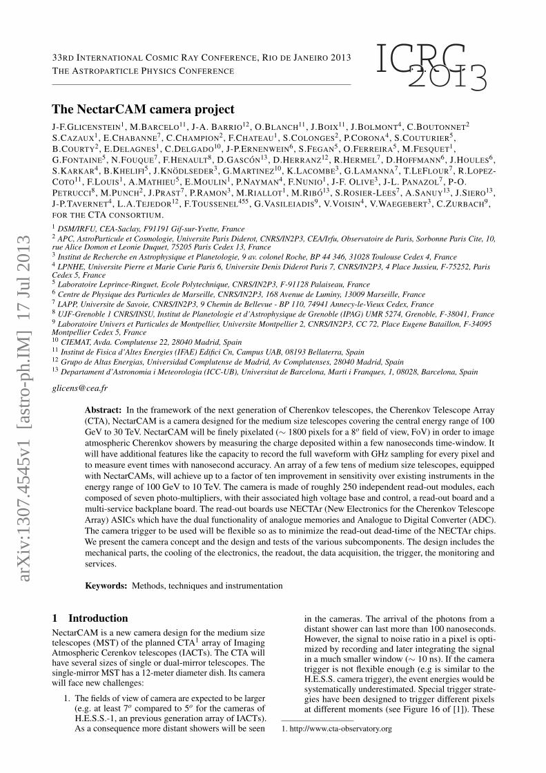
Figure 1: Early version (V0) of the NECTAr readout mod-ule used in the NectarCAM camera.
strategies still need to be tested. The trigger rate isalso expected to increase by a factor of two comparedto the previous generation of Cherenkov telescopes,as result of the larger field of view, potetially leadingto a larger dead time of the instrument.
2. Large timing gradients are expected in high-energygamma-ray events. Measuring these gradients im-proves the reconstruction of the events. Analyzingthe whole waveform also helps improve the hadronrejection (see e.g., Aliu et al. [3]). It has been esti-mated that a convenient reconstruction of the timegradient could be achieved with a time resolution of2 ns per pixel. To achieve a proper time resolution,it may be necessary to analyze the whole waveformsampled at 1 GHz. In the H.E.S.S. camera, an aver-age charge, time and time spread per pixel was cal-culated on-board for every triggered event. Sendingthe whole waveform of the event to the ground im-plies a data rate per event roughly 5 times larger thanthat of H.E.S.S. Taking into account the increase intrigger rate, the data rate will increase by an order ofmagnitude compared to H.E.S.S.
3. To achieve the aforementionned 2 ns time resolutionper pixel, the systematics on the time measurementsuch as the analogue bandwidth of the read-out sys-tem, or the delay between pixels due to the transittime spread of phototubes have to be carefully evalu-ated and corrected whenever possible.
As a result of the larger field of view and better timingcapabilities of the future Cherenkov cameras, it will bepossible to improve the reconstruction of the events and tohave a better hadron background rejection. However, thesenew capabilities present new challenges for Cherenkovtelescopes.
Two starting points for the NectarCAM are the architec-ture of the H.E.S.S.-2 camera and a read-out module: theNECTAr module [1]. Figure 1 shows an early version ofthe NECTAr module. This module converts the light of aset of photomultiplier tubes (PMTs) into a digital signalwhen some triggering conditions are fulfilled. The modulararchitecture of the H.E.S.S.-2 camera has the advantage ofavoiding costly cables and allowing for easy maintenance.The modular mechanical structure is described in Section 2.For the NectarCAM, modules are groups of seven pixels,with the associated front-end board, which are completelyautonomous in what concerns the power and control elec-tronics. The only cables that go to the ground are the inputpower voltage and optical fibers for network communica-tions and array trigger connections. Preliminary versions ofthe readout module exist. The photo-sensors, the readout
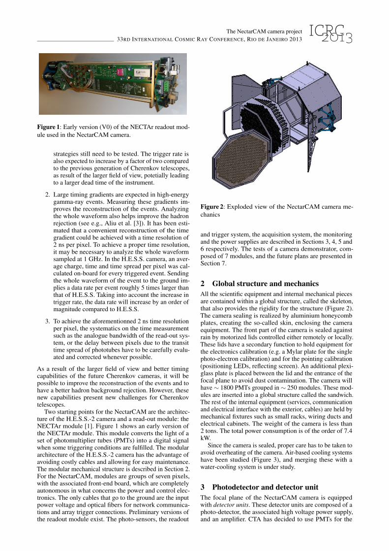
Figure 2: Exploded view of the NectarCAM camera me-chanics
and trigger system, the acquisition system, the monitoringand the power supplies are described in Sections 3, 4, 5 and6 respectively. The tests of a camera demonstrator, com-posed of 7 modules, and the future plans are presented inSection 7.
2 Global structure and mechanicsAll the scientific equipment and internal mechanical piecesare contained within a global structure, called the skeleton,that also provides the rigidity for the structure (Figure 2).The camera sealing is realized by aluminium honeycombplates, creating the so-called skin, enclosing the cameraequipment. The front part of the camera is sealed againstrain by motorized lids controlled either remotely or locally.These lids have a secondary function to hold equipment forthe electronics calibration (e.g. a Mylar plate for the singlephoto-electron calibration) and for the pointing calibration(positioning LEDs, reflecting screen). An additional plexi-glass plate is placed between the lid and the entrance of thefocal plane to avoid dust contamination. The camera willhave ∼ 1800 PMTs grouped in ∼ 250 modules. These mod-ules are inserted into a global structure called the sandwich.The rest of the internal equipment (services, communicationand electrical interface with the exterior, cables) are held bymechanical fixtures such as small racks, wiring ducts andelectrical cabinets. The weight of the camera is less than2 tons. The total power consumption is of the order of 7.4kW.
Since the camera is sealed, proper care has to be taken toavoid overheating of the camera. Air-based cooling systemshave been studied (Figure 3), and merging these with awater-cooling system is under study.
3 Photodetector and detector unitThe focal plane of the NectarCAM camera is equippedwith detector units. These detector units are composed of aphoto-detector, the associated high voltage power supply,and an amplifier. CTA has decided to use PMTs for the
The NectarCAM camera project33RD INTERNATIONAL COSMIC RAY CONFERENCE, RIO DE JANEIRO 2013
Figure 3: Simulation of a cooling airflow in the NectarCAMsandwich. The sandwich hosts ∼ 250 NECTAr modules.
Figure 4: Principle of NECTAr readout modules.
photodetectors of their single mirror telescopes. A candi-date PMT is the R11920-100 developed by Hamamatsu2.The R11920-100 PMT has a single photon electron signalFWHM of 2.5 to 3 ns. The light from the dead spaces be-tween PMTs will be collected by custom designed Winstoncones or lenses. The high voltage of the PMTs will be ob-tained from an external 24-V supply with an ASIC, similarto a chip designed for the KM3Net experiment [2]. The out-put from the PMTs is amplified by a wideband (450 MHz)16-bit amplifier called PACTA [4]. The large bandwidth ofthe PACTA allows a minimal distortion of the PMT sig-nal, and thus a better measurement of the arrival time ofdetected photons.
4 ReadoutAs illustrated in Figure 4, NECTAr modules are composedof 3 blocks. The block on the left hand side is composed of 7PMTs, each associated with its detector unit, as described inSection 3. The central block is the front-end board. Signalsfrom the detector units are amplified again in an ACTA[5]ASIC. At this level, the signal is divided into a low-gain,high-gain (relative gain 16) and a trigger channel. Thetrigger strategy is described in Section 5. The two first levels
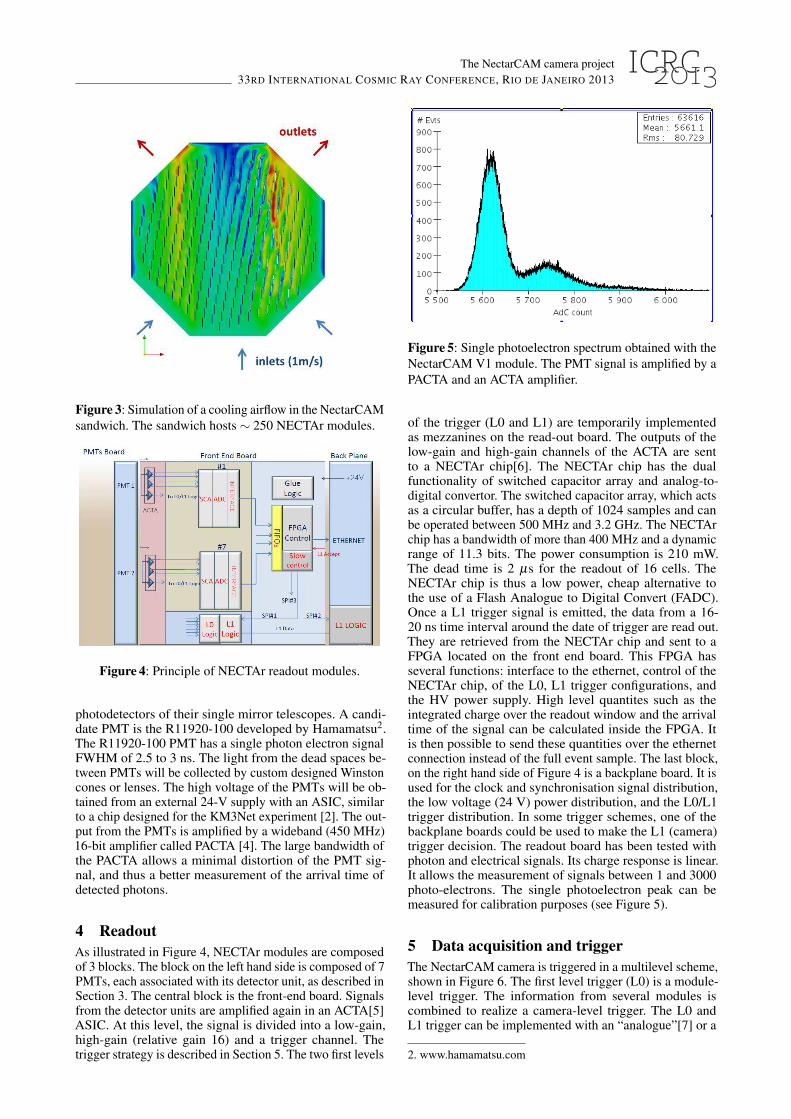
Figure 5: Single photoelectron spectrum obtained with theNectarCAM V1 module. The PMT signal is amplified by aPACTA and an ACTA amplifier.
of the trigger (L0 and L1) are temporarily implementedas mezzanines on the read-out board. The outputs of thelow-gain and high-gain channels of the ACTA are sentto a NECTAr chip[6]. The NECTAr chip has the dualfunctionality of switched capacitor array and analog-to-digital convertor. The switched capacitor array, which actsas a circular buffer, has a depth of 1024 samples and canbe operated between 500 MHz and 3.2 GHz. The NECTArchip has a bandwidth of more than 400 MHz and a dynamicrange of 11.3 bits. The power consumption is 210 mW.The dead time is 2 µs for the readout of 16 cells. TheNECTAr chip is thus a low power, cheap alternative tothe use of a Flash Analogue to Digital Convert (FADC).Once a L1 trigger signal is emitted, the data from a 16-20 ns time interval around the date of trigger are read out.They are retrieved from the NECTAr chip and sent to aFPGA located on the front end board. This FPGA hasseveral functions: interface to the ethernet, control of theNECTAr chip, of the L0, L1 trigger configurations, andthe HV power supply. High level quantites such as theintegrated charge over the readout window and the arrivaltime of the signal can be calculated inside the FPGA. Itis then possible to send these quantities over the ethernetconnection instead of the full event sample. The last block,on the right hand side of Figure 4 is a backplane board. It isused for the clock and synchronisation signal distribution,the low voltage (24 V) power distribution, and the L0/L1trigger distribution. In some trigger schemes, one of thebackplane boards could be used to make the L1 (camera)trigger decision. The readout board has been tested withphoton and electrical signals. Its charge response is linear.It allows the measurement of signals between 1 and 3000photo-electrons. The single photoelectron peak can bemeasured for calibration purposes (see Figure 5).
5 Data acquisition and triggerThe NectarCAM camera is triggered in a multilevel scheme,shown in Figure 6. The first level trigger (L0) is a module-level trigger. The information from several modules iscombined to realize a camera-level trigger. The L0 andL1 trigger can be implemented with an “analogue”[7] or a
2. www.hamamatsu.com
The NectarCAM camera project33RD INTERNATIONAL COSMIC RAY CONFERENCE, RIO DE JANEIRO 2013
Figure 6: Triggering scheme of the NectarCAM camera.
“digital” solution. The latency of the camera trigger is lessthan 400 nanoseconds. This is much less than the depth ofthe switched capacitor array in the NECTAr chip, so thattrigged events can be read back from the past. The triggedevents are time-stamped and sent to a camera server byethernet. Events on the camera server are accepted only ifthey are coincident with triggers from one or several othertelescopes. The typical trigger rate of a single telescope is5 kHz. The latency of the array trigger is a few µs. Singletelescope events can be time stamped with an accuracy ofa few (∼ 2) nanoseconds. The data acquisition follows themodel described in [9]. Before being sent to the cameraserver, data from NECTAr modules are concentrated in∼ 7 switches. The switches are linked to the camera serverthrough three 10 Gbit connections. The data rate between aNECTAr module and the switches is 2 Mbit/s, if only thetotal charge and arrival time of pixels are transferred. It is∼ 40 Mbit/s if all the samples in the region of interest aretransferred.
6 Slow control and servicesNectarCAM will have sensors to monitor the temperature,pressure and humidity inside the camera. Its safety will beensured with ambient light sensors, smoke detectors andby tracking the position of the lids and back doors. Mostsubsystems of the camera are controlled remotely. This isthe case for the calibration-related hardware (positionningleds), for the cooling system, for the DAQ crate and theclock distribution board. The monitoring/slow control ofthe NectarCAM will use either industrial solutions such asProgrammable Logic Controllers, or custom made boardswith FPGAs. The latter solution, where the sensors areaccessed by industrial buses such as I2C, has been used forthe H.E.S.S-2 telescope.
NectarCAM is powered by industrial low voltage sup-plies, since the High Voltage for operating the PMTs is cre-ated in the detector units (Section 3).
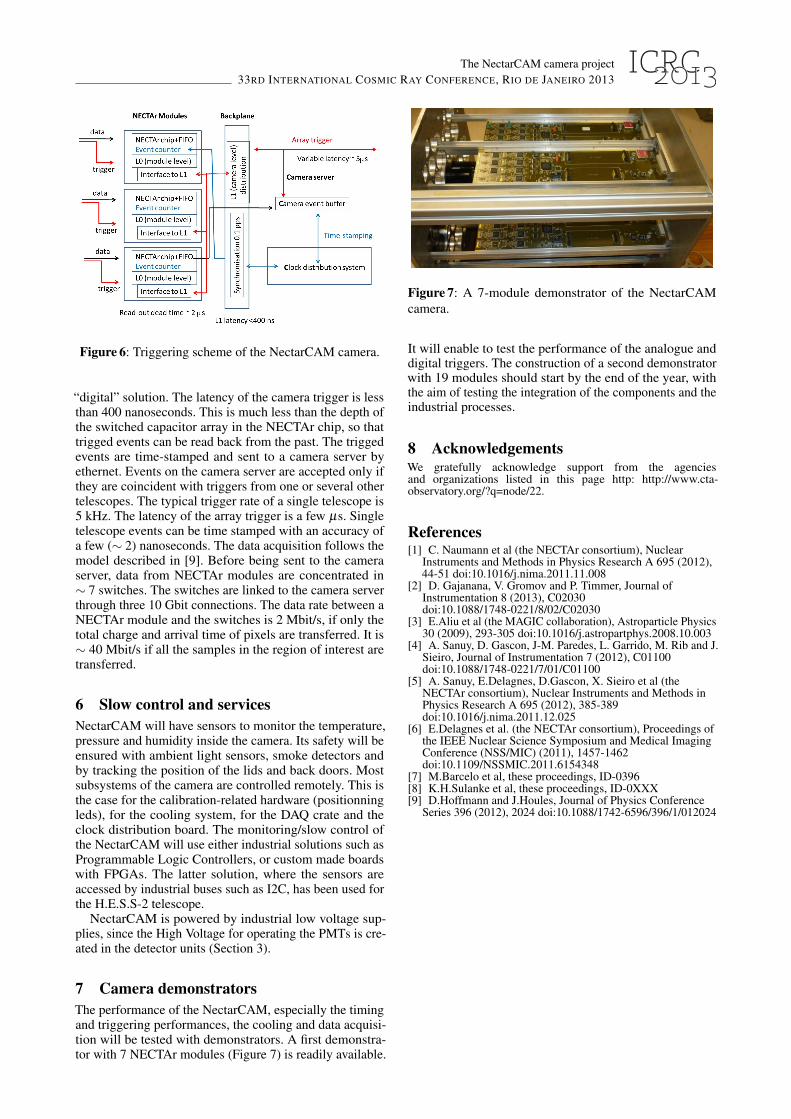
7 Camera demonstratorsThe performance of the NectarCAM, especially the timingand triggering performances, the cooling and data acquisi-tion will be tested with demonstrators. A first demonstra-tor with 7 NECTAr modules (Figure 7) is readily available.
Figure 7: A 7-module demonstrator of the NectarCAMcamera.
It will enable to test the performance of the analogue anddigital triggers. The construction of a second demonstratorwith 19 modules should start by the end of the year, withthe aim of testing the integration of the components and theindustrial processes.
8 AcknowledgementsWe gratefully acknowledge support from the agenciesand organizations listed in this page http: http://www.cta-observatory.org/?q=node/22.
References[1] C. Naumann et al (the NECTAr consortium), Nuclear
Instruments and Methods in Physics Research A 695 (2012),44-51 doi:10.1016/j.nima.2011.11.008
[2] D. Gajanana, V. Gromov and P. Timmer, Journal ofInstrumentation 8 (2013), C02030doi:10.1088/1748-0221/8/02/C02030
[3] E.Aliu et al (the MAGIC collaboration), Astroparticle Physics30 (2009), 293-305 doi:10.1016/j.astropartphys.2008.10.003
[4] A. Sanuy, D. Gascon, J-M. Paredes, L. Garrido, M. Rib and J.Sieiro, Journal of Instrumentation 7 (2012), C01100doi:10.1088/1748-0221/7/01/C01100
[5] A. Sanuy, E.Delagnes, D.Gascon, X. Sieiro et al (theNECTAr consortium), Nuclear Instruments and Methods inPhysics Research A 695 (2012), 385-389doi:10.1016/j.nima.2011.12.025
[6] E.Delagnes et al. (the NECTAr consortium), Proceedings ofthe IEEE Nuclear Science Symposium and Medical ImagingConference (NSS/MIC) (2011), 1457-1462doi:10.1109/NSSMIC.2011.6154348
[7] M.Barcelo et al, these proceedings, ID-0396[8] K.H.Sulanke et al, these proceedings, ID-0XXX[9] D.Hoffmann and J.Houles, Journal of Physics Conference
Series 396 (2012), 2024 doi:10.1088/1742-6596/396/1/012024