Embed Size (px)
Citation preview
THE NATIONAL SHIPBUILDING RESEARCH PROGRAM
TASK S-22
U.S. DEPARTMENT OF COMMERCE
MARITIME ADMINISTRATION
in cooperation with
BATH IRON WORKS CORPORATION
FINAL REPORT
Prepared by:
Sun Shipbuilding & Drydock Co.Dr. L. W. Sandor
Report Documentation Page Form ApprovedOMB No. 0704-0188
Public reporting burden for the collection of information is estimated to average 1 hour per response, including the time for reviewing instructions, searching existing data sources, gathering andmaintaining the data needed, and completing and reviewing the collection of information. Send comments regarding this burden estimate or any other aspect of this collection of information,including suggestions for reducing this burden, to Washington Headquarters Services, Directorate for Information Operations and Reports, 1215 Jefferson Davis Highway, Suite 1204, ArlingtonVA 22202-4302. Respondents should be aware that notwithstanding any other provision of law, no person shall be subject to a penalty for failing to comply with a collection of information if itdoes not display a currently valid OMB control number.
1. REPORT DATE 1980
2. REPORT TYPE N/A
3. DATES COVERED -
4. TITLE AND SUBTITLE The National Shipbuilding Research Program Task S-22 Weld DefectTolerance Study
5a. CONTRACT NUMBER
5b. GRANT NUMBER
5c. PROGRAM ELEMENT NUMBER
6. AUTHOR(S) 5d. PROJECT NUMBER
5e. TASK NUMBER
5f. WORK UNIT NUMBER
7. PERFORMING ORGANIZATION NAME(S) AND ADDRESS(ES) Naval Surface Warfare Center CD Code 2230 - Design Integration ToolsBuilding 192 Room 128 9500 MacArthur Bldg Bethesda, MD 20817-5700
8. PERFORMING ORGANIZATIONREPORT NUMBER
9. SPONSORING/MONITORING AGENCY NAME(S) AND ADDRESS(ES) 10. SPONSOR/MONITOR’S ACRONYM(S)
11. SPONSOR/MONITOR’S REPORT NUMBER(S)
12. DISTRIBUTION/AVAILABILITY STATEMENT Approved for public release, distribution unlimited
13. SUPPLEMENTARY NOTES
14. ABSTRACT
15. SUBJECT TERMS
16. SECURITY CLASSIFICATION OF: 17. LIMITATION OF ABSTRACT
SAR
18. NUMBEROF PAGES
126
19a. NAME OFRESPONSIBLE PERSON
a. REPORT unclassified
b. ABSTRACT unclassified
c. THIS PAGE unclassified
Standard Form 298 (Rev. 8-98) Prescribed by ANSI Std Z39-18
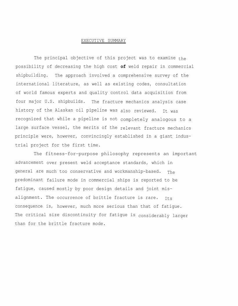
EXECUTIVE SUMMARY
The principal objective of this project was to examine the
possibility of decreasing the high cost of weld repair in commercial
shipbuilding. The approach involved a comprehensive survey of the
international literature, as well as existing codes, consultation
of world famous experts and quality control data acquisition from
four major U.S. shipbuilds. The fracture mechanics analysis case
history of the Alaskan oil pipeline was
recognized that while a pipeline is not
large surface vessel, the merits of the
also reviewed. It was
completely analogous to a
relevant fracture mechanics
principle were, however, convincingly established in a giant indus-
trial project for the first time.
The fitness-for-purpose philosophy represents an important
advancement
general are
predominant
over present weld acceptance standards, which in
much too conservative and workmanship-based. The
failure mode in commercial ships is reported to be
fatigue, caused
alignment. The
consequence is,
mostly by poor design details and joint mis-
occurrence of brittle fracture is rare. Its
however, much more serious than that of fatigue.
The critical size discontinuity for fatigue is
than for the brittle fracture mode.
considerably larger
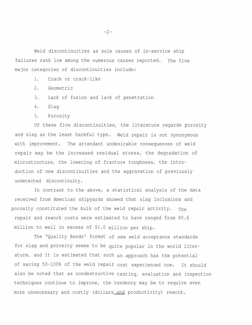
Weld discontinuities
failures rank low among the
-2-
as sole causes of in-service ship
numerous causes reported. The five
major categories of discontinuities include:
1. Crack or crack-like
2. Geometric
3. Lack of fusion and lack of penetration
4. Slag
5. Porosity
Of these five discontinuities, the literature regards porosity
and slag as the least harmful type. Weld repair is not synonymous
with improvement. The attendant undesirable consequences of weld
repair may be the increased residual stress, the degradation of
microstructure, the lowering of fracture toughness, the intro-
duction of new discontinuities and the aggravation of previously
undetected discontinuity.
In contrast to the above, a statistical analysis of the data
received from American shipyards showed that slag inclusions and
porosity constituted the bulk of the weld repair activity. The
repair and rework costs were estimated to have ranged from $0.6
million to well in excess of $1.0
The “Quality Bands" format
for slag and porosity seems to be
million per ship.
of new weld acceptance standards
quite popular in the world liter-
ature, and it is estimated that such
of saving 50-100% of the weld repair
also be noted that as nondestructive
an approach has the potential
cost experienced now. It should
testing, evaluation and inspection
techniques continue to improve, the tendency may be to require even
more unnecessary and costly (dollars and productivity) rework.
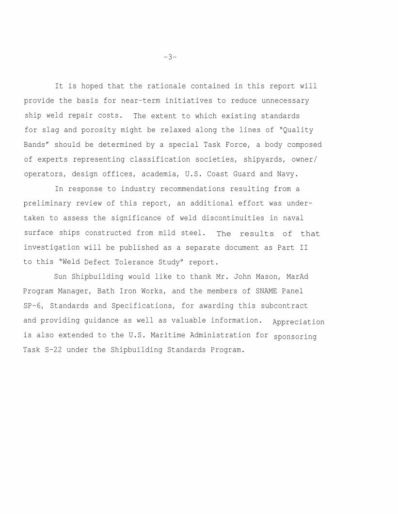
-3-
It is hoped that the rationale contained in this report will
provide the basis for near-term initiatives to reduce unnecessary
ship weld repair costs. The extent to which existing standards
for slag and porosity might be relaxed along the lines of “Quality
Bands” should be determined by a special Task Force, a body composed
of experts representing classification societies, shipyards, owner/
operators, design offices, academia, U.S. Coast Guard and Navy.
In response to industry recommendations resulting from a
preliminary review of this report, an additional effort was under-
taken to assess the significance of weld discontinuities in naval
surface ships
investigation
to this “Weld
constructed from mild steel. The results of that
will be published as a separate document as Part II
Defect Tolerance Study” report.
Sun Shipbuilding would like to thank Mr. John Mason, MarAd
Program Manager, Bath Iron Works, and the members of SNAME Panel
SP-6, Standards and Specifications, for awarding this subcontract
and providing guidance as well as valuable information.
is also extended to the U.S. Maritime Administration for
Task S-22 under the Shipbuilding Standards Program.
Appreciation
sponsoring
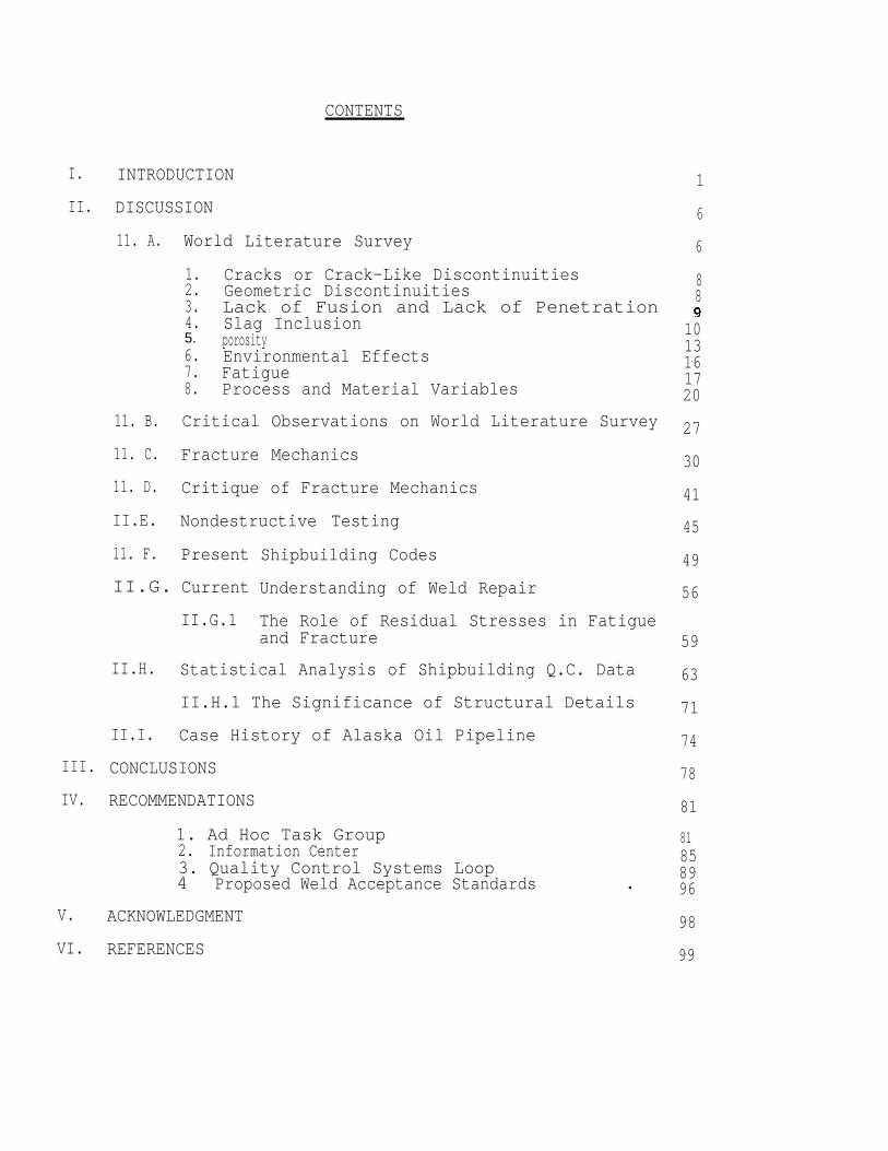
CONTENTS
I.
II.
III.
IV.
V.
VI.
INTRODUCTION
DISCUSSION
11. A.
11. B.
11. C.
11. D.
II.E.
11. F.
World Literature Survey
5.
1. Cracks or Crack-Like Discontinuities2. Geometric Discontinuities3. Lack of Fusion and Lack of Penetration4. Slag Inclusion
porosity 6. Environmental Effects7. Fatigue8. Process and Material Variables
Critical Observations on World Literature Survey
Fracture Mechanics
Critique of Fracture Mechanics
Nondestructive Testing
Present
II.G. Current
II.G.1
Shipbuilding Codes
Understanding of Weld Repair
The Role of Residual Stresses in Fatigueand Fracture
II.H. Statistical Analysis of Shipbuilding Q.C. Data
II.H.1 The Significance of Structural Details
II.I. Case History of Alaska Oil Pipeline
CONCLUSIONS
RECOMMENDATIONS
1. Ad Hoc Task Group2. Information Center 3. Quality Control Systems Loop4 . Proposed Weld Acceptance Standards
ACKNOWLEDGMENT
REFERENCES
1
6
6
88
1013161720
27
30
41
45
49
56
59
63
71
74
78
81
858996
81
98
99
I.
II.
QUALITY CONTROL SYSTEMS LOOP.
TABLE I: CHEMISTRY OF ALASKAN
111
PIPELINE STEEL. 115
III. EXEMPLARY FORMAT OF PROPOSED STANDARDS. 116
IV. FIGURE 1. GRAPHICAL ILLUSTRATION OF FATIGUE FAILURE MODE. 117
I. INTRODUCTION
The intent of the present program was to conduct a state of
the art review in the field of weld defect tolerance for commer-
cial shipbuilding applications. Specifically, this study was
directed at examining the possibilities of decreasing the high
cost of weld repair and outlining future trends and options for
new weld discontinuity standards founded upon more rational
engineering principles than the present codes. All along, it
has been recognized that such new standards would take a consid-
erable period of time to both develop and gain industry acceptance.
To this end, a project of this type should serve to act as a
catalyst or a means of initiating and ultimately obtaining the
consensus of the shipbuilding industry using the American Society
for Testing & Materials as a forum. It is hoped that the findings
of this program will set in motion the elements necessary to
bring about these stated objectives.
Corporate Science and Technology of Sun Ship was awarded in
August, 1978, a subcontract on “Weld Defect Tolerance Study” by
Bath Iron Works as part of the Shipbuilding Standards Program.
The weld defect tolerance study presupposes that introduction
of discontinuities into welds is unavoidable, regardless of type
of process used or degree of care exercised. Fortunately, not
all defects are harmful. Thus, not all defects require repair.
In fact, repairing an innocuous discontinuity would entail an
unnecessary cost added to the manufacture of a weldment (in our
case, a ship).
- 2 -
The real meaning and purpose of weld defect tolerance study
is not the lowerinq of product quality, but rather the outlining
of the conditions for avoiding unnecessary weld repair costs and
weldment degradation in general. It is a philosophy based upon
a “fitness-for-purpose” criterion.
The impetus for this program were advances in the field of
fracture mechanics. Fracture mechanics is a relatively new
engineering discipline which is basically an analytical technique
to assess the effects of discontinuities on the mechanical behav-
ior of structural components. With this analytical tool, the
effect of weld discontinuities could be determined with a much
higher degree of certainty then earlier empirical “rule of thumb”
type approaches. Recently,
new defect acceptance codes
fracture mechanics has made
with the use of fracture mechanics,
have been proposed. In addition,
it possible to analyze the effect
of defects in certain welded structures such as the Alaska pipe-
line (See Section II.I).
Initially, it was thought that there could be significant
benefit in using the fracture mechanics analytical approach on
a case by case basis to assess the effect of defects on ship-
building hull welds. This type of approach is similar to the
post welding analyses performed on the Alyeska pipeline. However,
this study will show that this case by case analysis does not
appear to have promise as a potential cost savings tool for
commercial shipbuilding. The significance of weld discontinuity
takes on different design and inspection meanings depending on
- 3 -
failure modes observed historically in a given welded structure.
In this context the three principal failure modes are brittle
fracture, fatigue, and elastic-plastic (or mixed mode). It has
been estimated that 70-90% of all industrial failures including
ships involved fatigue (l-3). The design philosophy for the
prevention of fatigue failure lies in careful details design (4).
Whilst the objective should be to avoid failure by any of these
modes, the consequences of fatigue failure are less disastrous
than those of brittle or elastic-plastic fracture. For fatigue
failure modes, larger size discontinuities can be tolerated and
catastrophic failure modes would largely be eliminated, particularly
when the ship is operated above the ductile-to-brittle transition
temperature. Fatigue failure mode gives warning time. For
brittle fracture conditions, the design philosophy is the most
rigorous, since the critical discontinuity size is very much
smaller than for general yield cases. The normal philosophy with
brittle fracture is to ensure that this mode of failure cannot
occur by selecting materials which are ductile under the design
operating conditions. For brittle materials the critical dis-
continuity size is very much smaller than for materials that would
fail by general yield. Naturally, the design philosophy required
if brittle materials are used is considerably less appealing from
a Practical as well as a cost standpoint. The use of such
materials in welded structures such as ship’s hulls is particularly
to be avoided because such structures are inevitably stressed
into the yield range as a result of locked in stresses (residual
stress) due to weld shrinkage and because of structural discontinuities.
- 4 -
Creep-Rupture failure mode is not relevant to ship failures
because it occurs at elevated temperatures.
The fracture mechanics approach to fatigue assessment makes
the tacit assumption that discontinuities are present in welds.
Crack initiation is therefore inconsequential, but crack propa-
gation is the overriding consideration.
One of the difficulties that was encountered in this study
was that ordinary strength structural steels are used for
commercial ship hulls. In terms of chemical composition these
steels are referred to as carbon-manganese steels. These steels
are obtainable in different grades as a result of different
steel making processes and/or chemistry. The net result of these
differences is a rather broad scatter in the fracture toughness
or fracture resistance of these steels. This makes it somewhat
difficult to make definitive statements at the present time
regarding the acceptability of specific defects without specific
fracture information on a given weldment.
The approach taken for studying the real meaning of fracture
mechanics principles in assessing the bona fide role of discon-
tinuities in commercial ship hull welds was the following:
A critical survey of the available world literature with a
specific view toward usefulness in shipbuilding was conducted.
World renowned experts from universities, research institutions,
and industry relative to the scope of this study were consulted.
All aspects of pertinent fracture mechanics principles based on
known failure modes that have occurred in commercial ship hulls
were reviewed. Nondestructive test methodologies, shipbuilding
-5 -
codes, current understanding of weld repair, and shipbuilding
quality control data as exist today were examined.The most
pre-eminent case history of fracture mechanics principles applied
to the world’s largest, single pipeline project was analyzed.
A synthesis of all this information was made and translated into
a benefit to the U. S. commercial shipbuilding industry.
Finally, formats for new weld acceptance standards are
proposed and directions for improving the overall shipbuilding
quality with a minimum of expenses involved are suggested.
- 6 -
II. DISCUSSION
II.A. World Literature Survey
The significance of weld discontintities is assessed on the
basis of their effect on the life and integrity of a welded
structure. The spectrum of weld discontinuity influence can
ranked in accord-cc with the nature of their influence upon
behavior of the structure which is a function of:
range from harmful to innocuous. Consequently, weld discontintities
are
the
1.
2.
3.
4.
5.
6.
7.
8.
9.
10.
11.
12.
13.
14.
Geometric shape of the discontinuity,
Acuity of the extremities of the discontinuity,
Location of the discontinuity in the weld as well
as ship location of the weld,
Amount and distribution of the discontinuity in
the weld,
Species of the operating stresses and their magnitude,
Environmental conditions (corrosion, temperature),
Welding processes,
Design conditions and presence of structural
discontinuities,
Material thickness,
Rate of loading,
Size of weldment,
Transients during ship operations,
Microstructure in general,
Material chemistry.
- 7 -
Defect-related factors affecting the significance of weld
discontinuities are type, size, shape, quantity, distribution,
orientation and location. To determine the significance of a
discontinuity in a weld by means of fracture mechanics principles
requires quantification of principal stresses, environmental
parameters (corrosivity, temperature), design conditions (stress
concentration), manufacturing conditions (joint misalignment),
defect dimensioning (depth, length) and fracture toughness
determination.
In decreasing order of harmfulness, the literature has
recognized the following weld discontinuities:
1. Crack or crack-like discontinuity,
2. Geometric discontinuity,
3. Lack of fusion (LOF) and lack of penetration (LOP),
4. Slag inclusion,
5. Porosity
There are two other ways of categorizing weld defects, namely:
1.1 Planar
1.2 Nonplanar
and
2.1 Surface
2.2 Buried
2.3 Through thickness
Let us now turn to the discussion of the five principal
categories of weld discontinuities.
- 8 -
1. Cracks or Crack-like Discontinuities
Cracks are regarded as the most detrimental defects owing
to their sharp extremities. The acuity of the extremities of
cracks or crack-like discontinuities gives rise to very short
fatigue crack initiation time; hence, crack propagation is
important.
Surface cracks are most harmful and are also subject to
environmental effects, which amplifies the adverse influence
of cracks, particularly in low toughness materials. Although
not without a total unabiguity, most experts in the field of
fracture mechanics agree that cracks ought not to be tolerated
in products especially in their manufacture. If, on the other
hand, a crack is detected in service of the welded product,
one can resort to the utilization of relevant fracture mechanics
principles by which to determine the life expectancy using the
lower bound level as Harrison suggests (5).
in his approach, when suggesting lower bound
Conservatism
conditions.
2. Geometric Discontinuities
These discontinuities are in general associated with
lies
the
weld profile, although misalignment, weld spatter, arc-strikes
and burn-through also fall in this category. In spite of their
pronounced harmful influence on fatigue strength, welds are
produced with undesirable contours. Large reinforcement angles
and discontinuities at toes of fillet welds are particularly
deleterious. Gurney (6) reported that the critical size of a
geometric discontinuity in fillet welds for a given leg length
decreased as the plate thickness increased.
- 9 -
If the crack propagation rate is slower in a given metal
than in another, the critical size of the weld discontinuity
can be increased. Geometric discontinuities are influential
in static behavior of welded structures to the extent that
they give rise to stress concentrations and change the load
bearing cross-sectional area.
3.
into
Lack of Fusion and Lack of Penetration
Lack of fusion is when the weld metal has not fused (melted)
the side wall of the joint. When the weld metal has not
penetrated to the bottom of the weld joint, it is called lack
of penetration.
The treatment of LOF and LOP must be related to the ductile-
to-brittle transition temperature of the specific ship steel in
question since they behave differently when the steel is above
or when it is below the transition temperature (TT). Below the
TT, both LOF and LOP are potentially harmful. They trigger
brittle fracture. If the steel is above the TT, they are slightly
worse than slag inclusions or porosity. This, then, suggests the
importance of defining the exact TT and the service conditions
of the ship.
The effect of LOF and LOP can be masked by weld metal over-
matching and reinforcement. The direction of the applied
alternating stress with respect to LOF and LOP is very important.
When the applied load is parallel to LOF and LOP the effect is
minimal, and the harmful influence is maximum when the direction
of stresses acting on these discontinuities is perpendicular.
- 1 0 -
This alludes to possibilities in different QC requirements for
shell butt welds from shell seam welds.
In high strength steels initiation time is minimal according
to Professor Lawrence, et al. (7). This apparent difference
explains the greater sensitivity of high strength steels to weld
discontinuities. If the ship steel is in the upper shelf region,
or above the crack-arrest-temperature (CAT), an initiated crack
is normally arrested once it leaves the tensile residual stress
field and the degraded microstructure region.
The significance of LOF and LOP in an aluminum alloy of
Al-4.4% Mg welded by MIG was investigated by Screm and Frattini
(8). They found that LOF and LOP were much more serious defects
than undercut, surface irregularity, macro- and microporosity.
The fatigue strength of this aluminum alloy in a 12 mm test
specimen thickness was reduced 60% by the presence of LOF and/or
LOP.
LOF/LOP have blunted extremities, therefore,
compared to slag inclusions by many researchers.
they have been
How much LOF/
LOP may be allowed depends upon their “aspect ratio”, location, and
orientation with respect to the applied load. The literature
regards LOF/LOP more deleterious than inclusions and certainly
more
4.
than porosity.
Slag Inclusion
While there are several welding methods used in shipbuilding
today, still the most widely utilized ones are first the shielded
metal-arc and then the submerged-arc processes. Both methods
are potential sources of slag inclusions that may be entrapped
- 1 1 -
in the weld. Multiple pass welds are more prone for non-metallic
inclusions than single pass welded joints.
Fluxes exert a pronounced influence upon the properties
and soundness of the resultant weld (9). Basic fluxes promote
low oxygen and/or sulphur contents in the weld metal, thereby
minimizing the formation of non-metallic inclusions. In a broader
sense, the type of submerged-arc flux used will influence the
quantity and species of foreign particles present in the weld
bead. Of the several manifestations of the influence of flux,
the discussion herein is confined to slag inclusions. These
non-metallic inclusions represent an incoherent phase in the
surrounding matrix. In the context of fracture mechanics, these
foreign particles are less harmful than cracks or crack-like
discontinuities due to configurational differences. The tensile
strength of the material is reduced in proportion to the projected
area of the slag. This effect is smaller on the yield strength.
The tensile ductility is reduced significantly by the presence
of slags (1). Stress concentration induced by a foreign particle
is less by virtue of not creating a void in the structure than
that caused by porosity irrespective of material containing
these defects (1, 10). The significance of slag inclusions is
treated in terms of their size, amount, distribution and location
within the weldment.
Fatigue test results are listed in order of increasing
length of non-metallic inclusions and plotted on a log S versus
log N diagram; where, S denotes the stress range and N signifies
the number of cycles (endurance). The diagram usually contains
- 1 2 -
five arbitrary Quality Bands: I, II, III, IV and V. (See
Appendix III).
Furthermore, the “Quality Bands” are set up for 97.5% or
99.5% confidence levels (11), also called probability of
survival (12).
Each band corresponds to a specific fatigue strength required
in a given structure in conformance with design criteria. For
a given size (length) slag particle as the stress range increases,
the number of cycles decreases. On the other hand, the shorter
the length of a non-metallic inclusion, the higher the endurance
limit for a specific stress range imposed on that weldment.
The quality categories have been set up on the basis of
(a) “as-welded” and (b) “stress-relieved” structures (12).
Various proposals can be found in the international literature
with regard to the treatment of defect interaction criteria and
multiple slag inclusions. For example, the British Draft Standards
(12) takes the view that “where multiple slag inclusions occur
on the same cross section and the distance between the defects
is less than 1.25 times the height of the larger defect, they
should be treated as a single planar defect with an overall
height equal to the distance between the outer extremities”.
If the detected non-planar defect is smaller than that given in
tables set up for (a) as-welded and (b) stress-relieved structures
for the respective quality categories and survival probabilities,
the defect is acceptable (12).
In terms of influence on fatigue, slag inclusions are similar
to porosity, which will be discussed next. Thus, analogous
- 1 3 -
criteria can be applied to slag (13). The international litera-
ture agrees on extending a considerably greater tolerance for
slag inclusions and porosity than existing codes permit (9-11,
14-15). This literature survey indicates that “Quality Bands”
as an approach to discontinuity acceptance standards have a
broad support throughout the world. The specific levels of
these bands may, however, be subject to certain engineering
critique.
5. Porosity
Porosity is regarded by a preponderance of the investigators
as the least harmful of all discontinuities. The influence of
porosity, however, is treated according to its location; i.e.,
surface or internal pores. In earlier publications, the shape
of porosity was believed to matter. Between spherical porosity
and herringbone porosity the former was regarded as the least
harmful of the two. Harrison (16) claims that herringbone
porosity is no more harmful than spherical porosity. He further
asserts that both types of porosity which occur in “normal
amounts in practice is acceptable for quality levels below “V”.
Boulton (10) mentions that surface porosity has a detrimental
effect on fatigue strength, particularly when the weld reinforce-
ment is removed. To improve fatigue life of weldments containing
surface porosity, the weld toe should be dressed to minimize
stress concentration. It has been observed that a fatigue failure
instead of originating at buried slag inclusions does so at
surface porosity. Pores in the surface are relatively more
detrimental than internal pores of the same size and amount
- 1 4 -
over a given weld length. Fatigue strength is most susceptible
to the presence of stress risers, therefore, superficial
porosity gives rise to a reduction in fatigue strength. The
influence of porosity can be minimized by weld reinforcement
and overmatching. When the strength of the weld metal is
considerably higher than that of the substrate, it is referred
to as overmatching. One has to distinguish between porosity in
butt welds and porosity in fillet welds. The reason being, butt
welds are relatively more critical in terms of application than
fillet welds. The surface tension and viscosity of both the
liquid weld metal and the molten flux are important in controlling
the propensity of the pore to rise to and escape from the surface.
In scattered form, porosity in amounts of up to 5-7% is
considered by the international literature as having no influence
on yield strength, ultimate strength, reduction in cross-sectional
area and slow bend ductility. Therefore, when static properties
are the controlling parameters in weldment behavior, code restric-
tions can be relaxed by a factor of 2-4 even for critical applica-
tions (l).
With preference to high cycle fatigue,
least harmful so long as the reinforcement
the porosity is the
of the weld is not
removed (17-19). When the reinforcement is removed, porosity may
be a nucleation site for fatigue crack extension at low levels
of porosity (17-18). Initially, the rate of decrease in fatigue
strength is appreciable (up to 50%), but after reaching about
5% in porosity the fatigue strength reduction rate decreases (17-19).
- 1 5 -
To influence the fatigue strength of fillet welds, porosity
is to be Located in the root and be present in large amounts.
Harrison (20) did a comprehensive analysis of all the available
information in the literature about the relationship between
porosity and fatigue stress of steel butt welds. He plotted the
data on a log S - log N graph and established five quality
categories for 0, 3, 8, 20 and 20 + % porosity levels (See
Appendix III).
After correlating large-scale, small-scale test results and
results obtained by an empirical relationship, Harrison drew the
conclusion that the quality levels so established were realistic.
Low-cycle fatigue (LCF) implies number of cycles less than 104
and stress levels very frequently in excess of the yield strength
as well as an appreciable strain at and around the tip of a grow-
ing crack. The microstructure and the yield strength in low-
cycle fatigue failure mode are generally regarded important.
Furthermore, the test methodology is essential in LCF. Reportedly,
the effect of 10% slag was drastic in strain-controlled tests,
while the same quantity of slag inclusions examined in load-
controlled tests was zero (13, 21). An analogous full assessment
on porosity is not yet apparent in world publications. Load-
controlled tests were done on porosity indicating zero effect
for 5% porosity on LCF.
To predict the wave environment for the worldwide mission
of a ship is undoubtedly difficult. However, an estimate of the
cyclic loading of a surface vessel may be made by defining from
- 1 6 -
an oceanographer’s book for the route concerning the representa-
tive sea-states over the years. This can be done by using R.M.S.
values of wave amplitudes or heights. The configuration of the
wave-spectrum, notably the peaks, defines the resultant stress
spectrum. There has been some debate whether or not the wave-
induced stresses should be treated as purely random. The
loading for marine structures is of neither constant amplitude
nor constant mean stress. Early in the life of the ship stormy
weather may occur inducing levels of stress composed of cyclic,
vibratory, mean stresses exceeding the yield strength of the
material giving rise to localized yielding at the so-called
“hot spots” (stress concentration sites) (22).
6. Environmental Effects
Ships operate in a corrosive environment. The ambient
temperature during the worldwide mission of a ship varies.
The understanding of corrosion is necessary. In corrosion
fatigue, it is important to know the actual level of stress since
at very high stresses the crack tip propagates so rapidly that
the corrosive medium has no time to react with the fresh crack
surface to enhance crack growth. This is because corrosion
fatigue is reaction rate limited. “Mechanism of corrosion fatigue
is most widely accepted to be related to hydrogen embrittlement”
(23). Hydrogen atoms are released at the fatigue crack tip by
an electrochemical reaction. The hydrogen atoms are absorbed
by the new metal surface, created by the actions of cyclic
loading. The continuation of these phenomena results in an
atmospheric pressure of hydrogen molecules (gas) in the crack
- 1 7 -
tip inducing hydrogen embrittlement which will increase the crack
extension rate. Factors which increase the rate of crack propa-
gation of corrosion-assisted fatigue are:
1.
2.
3.
4.
5.
6.
7.
Frequency of cyclic loading.
For a given stress range, the lower the frequency,
the fewer number of cycles required to failure.
Corrosion.
Dissolved oxygen content of sea water.
Ambient temperature.
Stress range.
pH of the solution (sea water).
Stress time wave form.
7. Fatigue
One explanation for such an extensive discussion of fatigue
is that, reportedly, the cyclic failure mode is dominant in
commercial ships, although the consequences of brittle fracture
are usually more serious - at times, catastrophic. Thus, in
terms of nature of the consequences of brittle fracture versus
fatigue failure, brittle fracture is normally ranked first.
Brittle fracture is indicative of through-thickness sudden failure
which can transcend the full length of the weldment (24). A
survey conducted in Japan between 1950-1969 indicated. that 75%
of the “cracks” found in decks and shell plates initiated at
toes and roots of fillet welds were caused by structural
discontinuities. The failure mode was low-cycle fatigue (3).
Other areas of failure were the after structures; those support-
ing the rudder and the propeller shafts brought on by vibration
resulting in high cycle-low stress fatigue.
- 1 8 -
The solution for fatigue treatment dates back to Palmgren
in 1924. Since then, so many hypotheses for fatigue failure
modes have surfaced in the world literature that it is rather
difficult to keep track of them. A few of the most prominent
but simple expressions include Miner’s Rule, Foreman’s Equation,
and Paris’ Formula (25).
The worldwide literature survey revealed that structural
design details and joint misalignment were the predominant
causes of ship failures and not weld defects (22, 26). The
survey has also shown that fatigue is the predominant failure
mode in commercial ships arising from a multiplicity of causes
(26-27). Weld defects as an exclusive cause of fatigue rank
very low among the various causes. The ratio of all known
causes combined to weld defects is 6:1. This implies that the
economic significance of reducing fatigue failure in commercial
ships lies in improving structural design details, in minimizing
misalignment. A recent survey conducted in the U. S. shipbuilding
industry has illustrated that most fatigue failures of ships occur
between the second and fourth year in service. Thereafter,
frequency of fatigue occurrence decreases (2).
From a fracture mechanics point of view, characterization
of fatigue means:
a. Safety from catastrophic failure.
b. Larger defect size permissible.
c. Utilization of cyclic stress range.
d. Defect dimensioning, location and interaction effects.
e. Determination
- 1 9 -
of crack propagation rate.
f. Limit to crack propagation.
g. Selection of confidence level.
h. Quality categorization.
i. Consideration for environment.
The fatigue crack propagation rate analysis should take into
account the environmental effects. Owing to the statistical
nature of fatigue failure analysis, notably of the simplified
version, a safety factor usually taken to be 4 is used. The
purpose of evoking safety factors is to take care of the inherent
difficulties in determining the exact magnitude of the principal
stresses, the complications in defining ambient conditions and
the fabrication disparities, as well as manufacturing deviations
from design details.
Improvements in fatigue life of welded structures invariably
entails
tensile
Amongst
methodologies that either reduce stress concentrations,
residual stresses or introduce compressive stresses.
such methods one can enlist the following:
- post weld heat treatment (stress relief)
- spot heating
- prior overloading
- local pressing
- weld profile controlling
- TIG or plasma dressing
- peening
- grinding
- quenching
- 2 0 -
- plastic coating
- cold working to induce surface hardening (viz.,
- compressive stresses)
- application of ductile materials with a lower
- modulus of elasticity in preselected locations of
- a welded structure
- optimizing the method of oxyacetylene cutting
- 2 1 -
The number of the investigators in the world who have
studied the fracture toughness of the heat affected zone (HAZ)
in carbon-manganese and alloy steels as well as other metallic
materials is stiply too numerous to mention by name. Without
intending to display a disrespect to earlier publications, we
enlisted in our reference only some of the more recently pub-
lished papers (28-36). Metallurgically, the HAZ has a complex
character for many reasons. We do not intend to go into a
detailed elucidation of them, rather to highlight the main facets
of the many competing reactions that can take place. In general,
the fracture toughness of steels is a function of the steel
making process, the welding process used, chemistries, thick-
nesses, restraint, strain aging, and configurations involved.
Furthermore, the resultant toughness of the HAZ will depend on
grain structure, amount,
constituents that may be
stresses, carbon content
shape, type and location of the various
present in the microstructure, the residual
and carbon equivalent. The relevance of
transition temperature characteristics, hardenability, micro-
segregation, ferrite morphology, role of specific alloying addi-
tions, welding
of weld metal,
of steel under
heat input level, number of weld passes, dilution
post-weld heat treatment of a particular chemistry
consideration must be recognized. As the plate
thickness and the carbon equivalent (CE) increase, the probability
for cold cracking (hydrogen embrittlement) increases. One approach
normally used in minimizing cold cracking is the raising of the
- 2 2 -
preheat temperature. The search still goes on for enhancing our
understanding of the interaction effects of these many phenomena.
From a yielding fracture mechanics point of view, a number
of points should be remembered when using C-Mn steels. The
transition temperature is influenced by specimen thickness in
the wake of altering the micromode of crack propagation (37).
The transition from cleavage fracture to ductile failure microvoid-
coalescence is brought about by means of a reduction in either
the crack length, the crack depth, or the ligament thickness.
The KlJ values (equivalent KlC computed from JlC) estimated
from JlC values measured in 10 mm thick test specimens are not
of necessity equivalent to KlC determined in 100 mm thick test
samples. The discrepancy is a result of inequality in stress
triaxialities between small and large specimens and the variance
in the micromode of fracture initiation. Much of the KlC values
in earlier publications were derived from the utilization of
small specimens; non-representative of the actual material thick-
ness.
Engineering critical assessment of weld defects is done
for the purpose of defining acceptable, harmless discontinuities
present in a structure without a sacrifice in product reliability
and survivability. The economic harmony between quality control
and “fitness-for-purpose” philosophy has received considerable
attention in the literature. Some authors have stated that “it
becomes necessary in the present climate of economic stringency
- 2 3 -
to examine the possibilities of effecting savings in cost by
the acceptance of deliberate reductions in quality standards”
(38). If this were true, the fitness-for-purpose philosophy
should deserve an automatic rejection. Defect tolerance study
must not be construed by anyone to mean "deliberate reductions
in quality standards”. Rather, we must emphasize that this new
philosophy signifies improvement in both quality and process
through better understanding of the interrelationship between
process used and concomitant quality.
The degree of departure from the ideal “as-designed” joint
by any design criteria is based on some implicit considerations
for:
1. Presence of weld defects, and
2. Misalignment of joints
Basar, et al (2) studied the present-day hull construction
and inspection procedures to determine the factors leading to
and the extent of structural deviations from the ideal, theoretical
design in U. S. shipyards. They also investigated the “welding
flaws” causing a departure from ideality. Deviations were divided
into:
a) “normal deviations experienced”
b) “maximm deviations expected”
Their approach was analogous to the Japanese methodology that
had led to “Japanese Shipbuilding Quality Standards--Hull Part”.
The Japanese have developed standard tolerances (or standard range)
and allowable limits (or tolerance limits) by taking actual
-24-
measurements
shipyards developing histograms for measured deviations and
from this established:
a) Standard range
b) Tolerance limits for each structural deviation
considered
As for deviations in welds (or weld geometry) they looked
for:
1. Bead shape including size, undercut, reinforcement.
2. Angular distortion of welding joint.
3. Short bead.
4. Arc strike.
5. Welding done at low ambient temperatures.
6. Weld spatter.
The allowable limits refer to a range beyond the standard
tolerances. The allowable limits mean that the product is still
acceptable without making modifications to it in the post-process
operations (39).
The Japanese quality control standards and practices have
been accepted by both the owner/operators and the classification
societies. A similar approach was taken and a system developed
by Det Norske Veritas (40).
One shipyard radiographed three ships (oil tankers) 100%
in order to determine the percentage of weld defects (2). It was
found that 15-30% of the welds x-rayed had “some defects".
Unfortunately, the report does not identify the type, size and
location of weld defects to make a fracture mechanics assessment.
- 2 5 -
In further reference to fatigue failure, the report states that
" cracks or structural failures have been reported as sea-
way damage or as design problems for which reinforcing was the
remedy, when in fact the problem might have been misalignment
or faulty welding”. During shipbuilding, repair activities were
quite varied in completeness and depth among shipyards surveyed.
Some of the observations noted in the report (2) concerning
welding are worthy of mention. Fairing by heating in midships
and other plating which may be subject to high stresses has to
be approved by the surveyor. Examination of weld quality by
“radiographic or ultrasonic inspection or both is to be used
when the overall soundness of the weld cross-section is to be
evaluated. Magnetic particle or dye penetrant inspection or
both is to be used when investigating the outer surface of welds
or may be used to check back chipped, ground or gouged joints
prior to depositing subsequent passes”. The locations and
extent of X-ray or UT inspections are indicated in the NDT
rules of the American Bureau of Shipping. Specific locations
are generally subject to the approval of the attending surveyor.
Very few ships that were reportedly inspected in accordance
with previous or current structural and weld tolerance standards
have failed in service. Four examples of ship failures were
studied and found that misalignment, design details and weld
defects caused fatigue cracking. There is no data on “in-service”
deviations reported by ship owners, only “recollections”. These
recollections
- 2 6 -
appear to indicate that in a number of vessels,
structural deficiencies have developed in service, which could
be traced back to initial structural deviations (2). Most yards
rely on experience and know-how of their own production super-
visors as well as that of regulatory body inspectors and owner/
operator representatives. The dominant factors in assessing
most structural deviations appear to be such abstract opinions
as “good marine procedure”, or “pleasing to the eye”. Standards
are used as "guides”, which are put to a rigorous testing only
in litigation cases (2).
From these observations-it should be evident that formulation
of new standards based on an engineering rationale and a fresh
re-examination of the system are overdue. Codes and Standards
ought not to be regarded as a piece of document reflecting some
sort of a status quo, for processes of manufacture do change.
Materials improve and their understanding is gradually enhanced.
Some standards have
of the significance
a provisional basis
been modified to include current understanding
of certain discontinuities, but mostly on
(7).
- 2 7 -
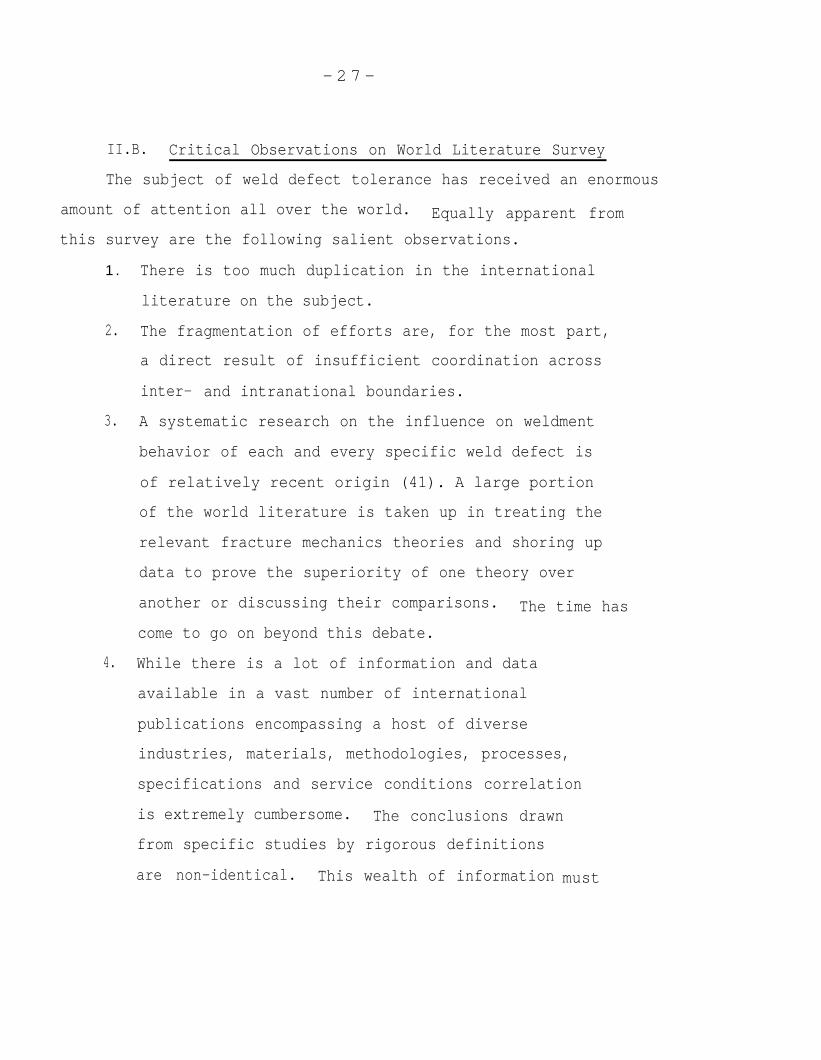
II.B. Critical Observations on World Literature Survey
The subject of weld defect tolerance has received an enormous
amount of attention all over the world. Equally apparent from
this survey are the following salient observations.
1 .
2.
3.
4.
There is too much duplication in the international
literature on the subject.
The fragmentation of efforts are, for the most part,
a direct result of insufficient coordination across
inter- and intranational boundaries.
A systematic research on the influence on weldment
behavior of each and every specific weld defect is
of relatively recent origin (41). A large portion
of the world literature is taken up in treating the
relevant fracture mechanics theories and shoring up
data to prove the superiority of one theory over
another or discussing their comparisons. The time has
come to go on beyond this debate.
While there is a lot of information and data
available in a vast number of international
publications encompassing a host of diverse
industries, materials, methodologies, processes,
specifications and service conditions correlation
is extremely cumbersome. The conclusions drawn
from specific studies by rigorous definitions
are non-identical. This wealth of information must
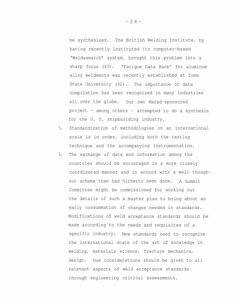
- 2 8 -
5.
6.
be synthesized. The British Welding Institute, by
having recently instituted its computer-based
“Weldasearch” system, brought this problem into a
sharp
alloy
State
focus (43). “Fatigue Data Bank” for aluminum
weldments was recently established at Iowa
University (42). The importance of data
compilation has been recognized in many industries
all over the globe. Our own Marad-sponsored
project - among others - attempted to do a synthesis
for the U. S. shipbuilding industry.
Standardization of methodologies on an international
scale is in order, including both the testing
technique and the accompanying instrumentation.
The exchange of data and information among the
countries should be encouraged in a more closely
coordinated manner and in accord with a well though-
out scheme than had hitherto been done. A Summit
Committee might be commissioned for working out
the details of such a
early consummation of
Modifications of weld
made according to the
master plan to bring about an
changes needed in standards.
acceptance standards should be
needs and requisites of a
specific industry. New standards need to recognize
the international state of the art of knowledge in
welding, materials science, fracture mechanics,
design. Due considerations should be given to all
relevant aspects of weld acceptance standards
through engineering critical assessments.
- 2 9 -
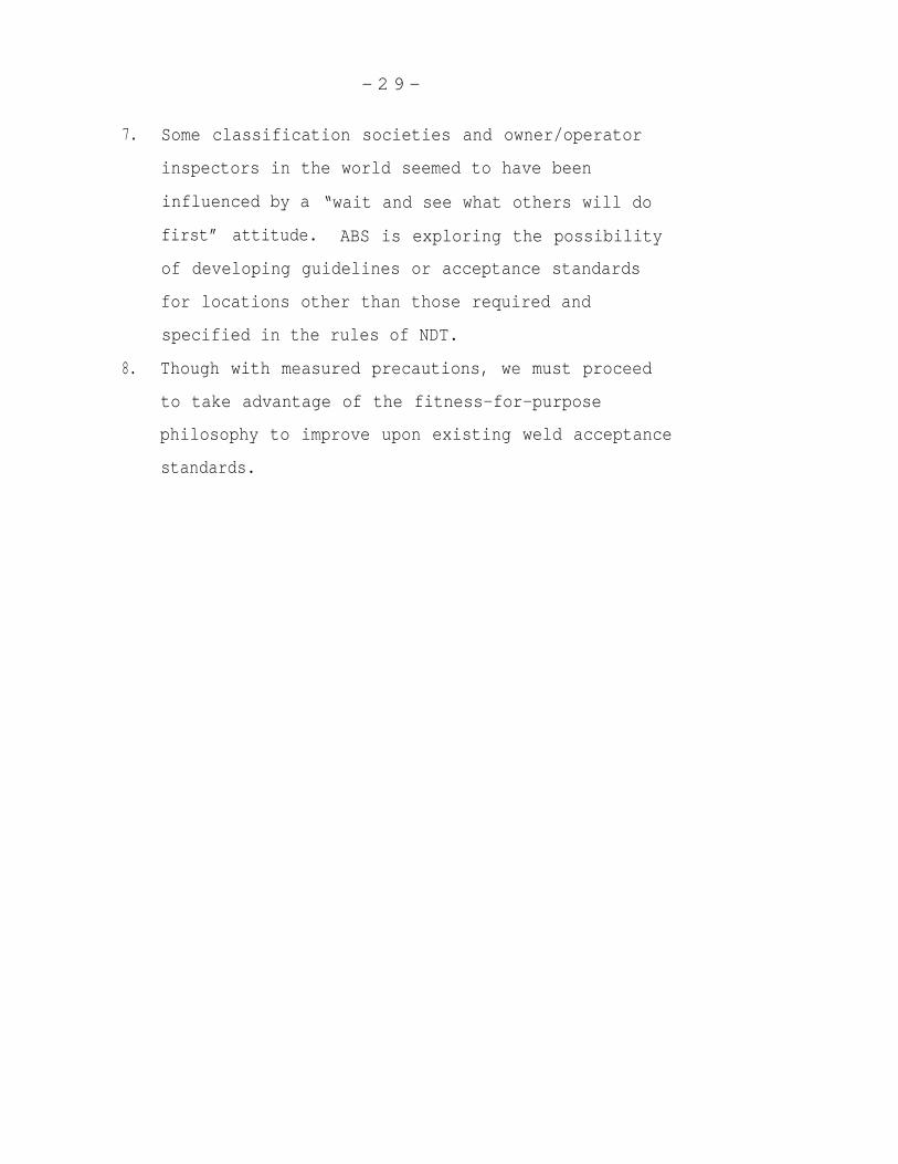
7. Some classification societies and owner/operator
inspectors in the world seemed to have been
influenced by a “wait and see what others will do
first” attitude. ABS is exploring the possibility
of developing guidelines or acceptance standards
for locations other than those required and
specified in the rules of NDT.
8. Though with measured precautions, we must proceed
to take advantage of the fitness-for-purpose
philosophy to improve upon existing weld acceptance
standards.
- 3 0 -
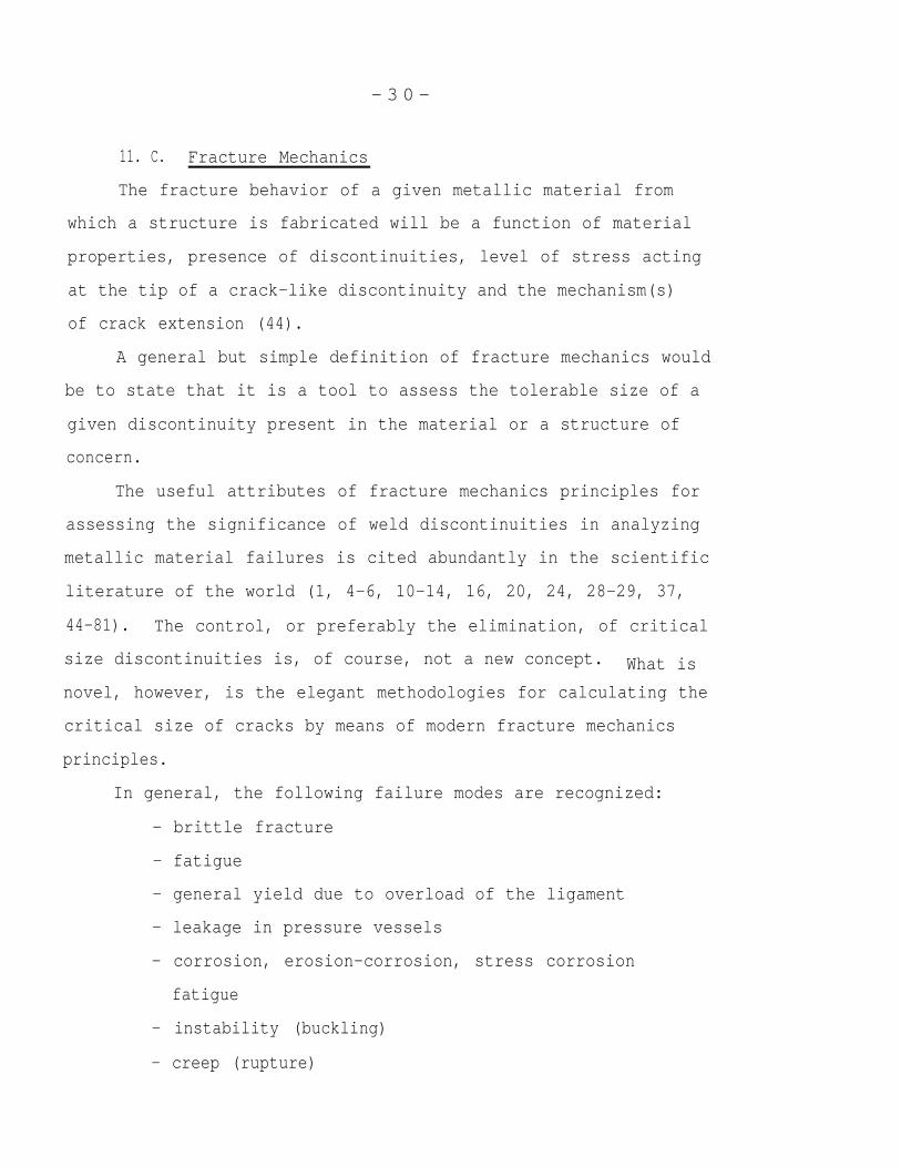
11. C. Fracture Mechanics
The fracture behavior of a given metallic material from
which a structure is fabricated will be a function of material
properties, presence of discontinuities, level of stress acting
at the tip of a crack-like discontinuity and the mechanism(s)
of crack extension (44).
A general but simple definition of fracture mechanics would
be to state that it is a tool to assess the tolerable size of a
given discontinuity present in the material or a structure of
concern.
The useful attributes of fracture mechanics principles for
assessing the significance of weld discontinuities in analyzing
metallic material failures is cited abundantly in the scientific
literature of the world (1, 4-6, 10-14, 16, 20, 24, 28-29, 37,
44-81). The control, or preferably the elimination, of critical
size discontinuities is, of course, not a new concept. What is
novel, however, is the elegant methodologies for calculating the
critical size of cracks by means of modern fracture mechanics
principles.
In general, the following failure modes are recognized:
- brittle fracture
- fatigue
- general yield due to overload of the ligament
- leakage in pressure vessels
- corrosion, erosion-corrosion, stress corrosion
fatigue
- instability (buckling)
- creep (rupture)
- 3 1 -
Many hypotheses for treating the various forms of failure
have been developed by the world scientific fraternity, of
which linear elastic, elastic-plastic, fatigue and plastic
instability have received most attention. Fracture mechanics
treatment of fatigue is by far more empirical in nature than
either linear elastic or elastic-plastic.
In barest essentials, fracture mechanics entails an under-
standing of the ductility of materials, or the behavior of a
given material in which a defect lies and is under stress.
Therefore, fracture
analysis of:
a. stress
b. Defect
mechanics
c. Material
d. Environment
implicitly involves a thorough
a. Stress analysis consists of measuring and calculating
all stresses that operate and act at the tip of the
defect in question; that is, primary stress across
the section thickness, bending stress, secondary
stress (thermal and residual) and peak stress (which
occurs at stress concentration sites).
b. Nondestructive testing (NDT) of the weldment, including
parent material, heat-affected zone and the weld
constitutes defect analysis. Defect dimensioning and
detection are critically dependent upon NDT.
the level of confidence in defect analysis is
related to the NDT selected and the extent of
conducted.
Therefore,
directly
inspection
- 3 2 -
c.
d.
The
principle
Material analysis involves destrictive testing
of the parent material in order to determine its
fracture toughness. Fracture toughness is a measure
of
In
an
be
the material’s resistance to crack propagation.
defining the rate of fatigue crack propagation,
analysis of environmental parameters must also
taken into account. The extent to which environmental
parameters influence fatigue crack propagation is
reaction rate-limited.
fracture mode determines which fracture mechanics
is to be applied. The fracture mode can be judged from
the operating stresses (level, type), weldment geometry, environ-
ment and material properties. Fracture mechanics principles
have been developed for the ensuing failure modes:
• brittle fracture
● elastic-plastic failure (general yield)
• fatigue failure
Fracture mechanics principles are regarded by most experts
as reliable in predicting if and when a given weld defect is
harmful or innocuous. It is not the intention of this study
to give these principles a full treatment herein, rather to
present their brief outlines and salient aspects for the sake
of relevancy to the underlying theme of the project. The reader
who wishes to take a closer look at fracture mechanics theories
may consult the various references to this report or any one of
the copious publications available on the subject.
- 3 3 -
Brittle fracture is handled by Linear Elastic Fracture
Mechanics (LEFM), giving rise to K1c = critical stress intensity
factor. LEFM is used for stress levels below the intrinsic
uniaxial yield stress (0. 2% offset) of the material in which
the weld discontinuity of interest lays. The stresses must be
considered in the vicinity of the crack tip. According to the
British Draft Standards (12), if, due to a
and principal stresses acting upon it, the
factor K1 is equal or less than 0. 7 x Klc,
regarded as acceptable. LEFM is also used
given discontinuity
stress intensity
the defect may be
below the ductile-
to-brittle transition temperature where plane strain conditions
dominate.
The known elastic-plastic fracture mechanics analyses include
plastic-instability (Irwin’s theory) and a semi-empirical method-
ology developed by Kiefner. The original basic concepts have
undergone a great deal of improvements and refinements since
their respective first appearance in the world literature.
The most widely used elastic-plastic theories include COD
and the J-integral methods. The latter (Jlc) is used in the
Both prin-
ciples can be applied to the ductile-to-brittle
transition region (elastic-plastic zone).
an index or a measure of fracture toughness of a given material
of interest exposed to elastic-plastic conditions (regimes),
i.e., non-linear and elastic behavior.
- 3 4 -
The National Bureau of Standards (60) gives Jlc the follow-
ing definition: the rate of change of potential energy with
respect to crack area and is proportional to the energy required
to initiate fracture in a flawed specimen subjected to monoton-
ically increasing loads. The test results in a J-integral curve.
The Landes-Begley J-test involves (for ferritic steels and their
weldments) the loading of a specimen to a predetermined displace-
ment (crack growth) such that a subcritical crack extension
transpires. The specimen is unloaded and subsequently heat
treated to tint (oxidize) the crack growth. Thereafter, the
specimen is fractured into halves intentionally so as to measure
at 3 points equidistant across the specimen thickness, the obtained
crack extension.
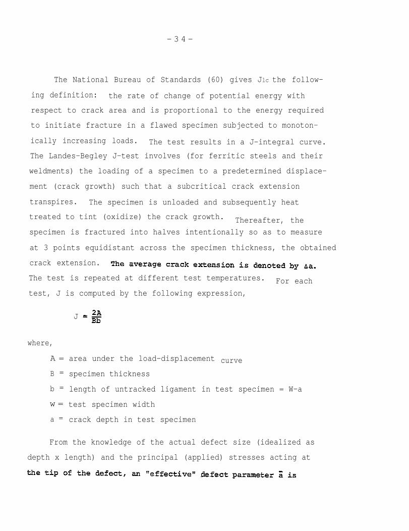
The test is repeated at different test temperatures. For each
test, J is computed by the following expression,
J
where,
A =
B =
b =
w =
a =
area under the load-displacement
specimen thickness
curve
length of untracked ligament in test specimen = W-a
test specimen width
crack depth in test specimen
From the knowledge of the actual defect size (idealized as
depth x length) and the principal (applied) stresses acting at
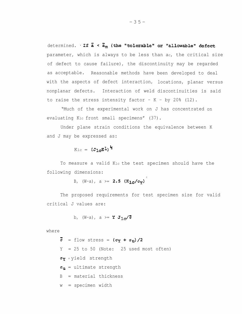
- 3 5 -
determined.
parameter, which is always to be less than ac, the critical size
of defect to cause failure), the discontinuity may be regarded
as acceptable. Reasonable methods have
with the aspects of defect interaction,
nonplanar defects. Interaction of weld
been developed to deal
locations, planar versus
discontinuities is said
to raise the stress intensity factor - K - by 20% (12).
“Much of the experimental work on J has concentrated
evaluating Klc front small specimens” (37).
on
Under plane strain conditions the equivalence between K
and J may be expressed as:
Klc =
To measure a valid
following dimensions:
B, (W-a), a >=
Klc the test specimen should have the
2
The proposed requirements for test specimen size for valid
critical J values are:
b, (W-a), a >=
where
= flow stress =
Y = 25 to 50 (Note: 25 used most often)
= yield strength
= ultimate strength
B = material thickness
w = specimen width
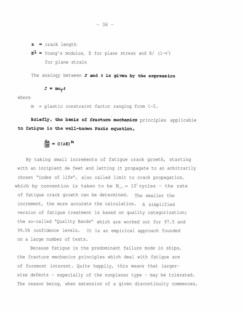
- 36 -
crack length
Young’s modulus, E for plane stress and E/ (1-v2)
for plane strain
The analogy between
Ywhere
m = plastic constraint factor ranging from 1-2.
principles applicable
By taking small increments of fatigue crack growth, starting
with an incipient de feet and letting it propagate to an arbitrarily
chosen “index of life”, also called limit to crack propagation,
which by convention is taken to be Ncrit = 105 cycles - the rate
of fatigue crack growth can be determined. The smaller the
increment, the more accurate the calculation. A simplified
version of fatigue treatment is based on quality categorization;
the so-called “Quality Bands” which are worked out for 97.5 and
99.5% confidence levels. It is an empirical approach founded
on a large number of tests.
Because fatigue is the predominant failure mode in ships,
the fracture mechanics principles which deal with fatigue are
of foremost interest. Quite happily, this means that larger-
size defects - especially of the nonplanar type - may be tolerated.
The reason being, when extension of a given discontinuity commences,

- 3 7 -
fatigue growth takes place slowly and is usually arrested when
it moves out of the stress field. Since in welded structures
discontinuities are present and ought to be viewed as cracks,
the design for fatigue related applications consists of calcu-
lations for crack propagation (22). . LEFM has a limited use-
fulness in commercial ships since brittle fracture seldom occurs
(80). However, due to the
fracture, it should not be
In welded structures,
catastrophic nature of brittle
totally ignored.
local yielding can originate either
from welding residual stresses which may reach yield stress
magnitude and possibly be additive to the applied stress, or it
may stem from stress concentrations and may exceed the yield
strength of the material (57).
Design curves have been derived by the crack tip opening
displacement at specific design temperatures, stress conditions
(residual stress inclusive), fracture toughness value of the
parent material and the weld. From this information the allowable
defect size (parameter can be calculated. The actual.
test involves weldments with either a natural or an artificial
discontinuity. Starting at a certain level of applied stress,
said weldment is, then, subjected to increasing levels of applied
stress until failure occurs. Then a comparison of the original
design stress with the stress at which the weldment with its
defect failed is
is less than the
applied stresses
original defect:
made. If the stress at which failure occurred
design stress, the test is repeated at lower
until no failure occurs with the same size
- 3 8 -
The attractiveness of fracture mechanics has to do with the
fact that it provides a systematic framework for analysis and
makes predictions possible for geometries other than those al-
ready tested by evoking the so-called geometric factor.
The two basic steps for the calculation of fatigue life are
(a) the utilization of S-N curves and (b) the figuring of damage
accumulation by means of the simple Paris formula (12, 28, 82-85).
Information regarding frequency of loading, stress ranges involved,
crack size, shape, and environmental factors are also necessary.
The literature survey demonstrates a reasonable agreement on
crack propagation as constituting the bulk of the fatigue life
in commercial ships involving low strength steel weldments. A
graphical illustration of fatigue failure mode is shown in
Figure 1 (see Appendix IV).
Normally, crack initiation is important in high strength,
brittle materials subjected to high mean stress levels, or in
low strength materials exposed to temperatures below their
respective ductile-to-brittle transition temperatures.
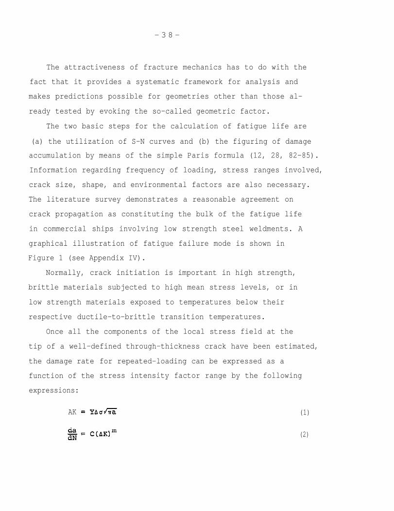
Once all the components of the local stress field at the
tip of a well-defined through-thickness crack have been estimated,
the damage rate
function of the
expressions:
for repeated-loading can be expressed as a
stress intensity factor range by the following
AK (1)
da (2)
- 3 9 -
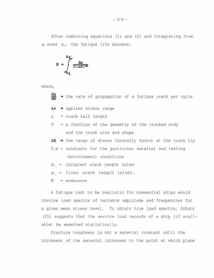
After combining equations (1) and (2) and integrating from
ai over af, the fatigue life becomes:
where,
a =
Y =
C,m =
a i =
a f =
N =
the rate of propagation of a fatigue crack per cycle
applied stress range
crack half length
a function of the geometry of the cracked body
and the crack size and shape
the range of stress intensity factor at the crack
constants for the particular material and testing
(environment) conditions
incipient crack length (size)
final crack length (size).
endurance
tip
A fatigue test to be realistic for commercial ships would
involve load spectra of variable amplitude and frequencies for
a given mean stress level. To obtain true load spectra, Schutz
(25) suggests that the service load records of a ship (if avail-
able) be examined statistically.
Fracture
thickness of
toughness is
the material
not a material constant until the
increases to the point at which plane
- 4 0 -
strain (brittle conditions) develops. The level of confidence
in fracture toughness values is critically dependent on the
degree of accuracy associated with the determination of:
1. The actual operating conditions;
2. Detection and determination of weld discontinuities;
3. The extent of NDT performed on a given welded structure.
Point (3) involves explicitly the cost of inspection plan
required. At this juncture, it might be well to remind our-
selves that we not trade off the reduction in the costs of weld
repair for the increase in the costs of NDT inspection for the
purpose of establishing the maximum level of confidence in
predicting structural behavior by fracture mechanics principles.
The application of fracture mechanics principles has been
extended to include, in addition to ferrous materials, non-ferrous
materials such as aluminum alloys (7, 86-87). Since steel is
the primary material for commercial shipbuilding, the weld
defect tolerance
discussed here.
of non-ferrous alloys will not, therefore, be
- 4 1 -
II.D. Critique of Fracture Mechanics
Like all else, fracture mechanics is not totally immune to
criticism. The accuracy of results obtained by fracture
mechanics is a direct function of:
1. NDT
2. Stress analysis
3. Fracture toughness test method
Fracture mechanics does not provide a guarantee that detrimental
defects may not be
side the inspected
about the level of
present somewhere in the welded structure out-
area. Nor does fracture mechanics tell anything
conformity to specifications and ship-to-ship
variability. To attain 100% confidence in the soundness of all
ship hull welds would necessitate 100% inspection of full reliability.
This would naturally be cost-prohibitive. This suggests that the
confidence in the overall integrity of the ship hull must be
enhanced by some other sensible ways such as the systems approach,
to be discussed later. A debate over artificially introduced
defects and generic flaws has produced certain difficulties and
some disagreement in terms of acuity, ductility, residual stress
state, stress field, microstructure and stress intensity (88).
One of the projects Professor Lundin is currently working on
deals with “Characterization and Nature of Discontinuities iii
Steel Weld Metals”. In it, he is investigating “localized
embrittlement adjacent to weld discontinuities. When this
embrittlement occurs, there is a greater possibility of brittle
fracture because the effective flaw size is that of the
discontinuity plus the embrittled region” (89).
- 4 2 -
the
the
The international literature contains profuse references to
importance of large scale tests for such reasons as including
full scope of the residual stress and simulating bona fide
structural and service conditions (12, 18, 45, 88,
more, one of the most frequent criticisms levelled
fracture mechanics is that “it is far from certain
90). Further-
against
to what
extent their application can always be relied upon. Thus, there
is a strong incentive for carrying out representative tests of
large scale in order to include as many factors of uncertainty
as possible. This is particularly so with
Only in this way can the accountability of
smaller scale tests be checked out and, at
assurance” (90).
The basic principles
is the data acquired for
respect to fatigue.
predictions from
the same time, give
of fracture mechanics are sound. It
conducting relevant fracture mechanics
calculations upon which the accuracy of the predicted values
depend. The input is in direct relationship with the outcome.
In the strictest of sense, the ship itself is, of course, the
only "test sample” of ultimate reliability.
The implication of weld discontinuity assessment on a
fitness-for-purpose basis is thorough examination (12). If
and when thins is not possible, safety factors are incorporated.
Conceptually, fracture mechanics principles mean the obtainment
of “safe” results. The degree of this "safety” in the principles
is in part a function of the difficulty in assigning definitive
values to the terms and constants of the “mathematical formula-
tions”.
There is a need to avoid certain confusing aspects of
fracture mechanics such as what constitutes, for example, the
actual Critical Crack Opening Displacement (COD). At present,
1. COD at fracture.
2. COD at the sign of first instability.
3. COD at which an arbitrary amount of crack extension
occurs.
4. COD at first attainment of the maximum force.
The size of the test specimens should be unified. The
published literature speaks of such divergent matters as:
1 .
2.
3.
4.
5.
6.
7.
Compact tensile specimens.
Full-size specimens.
Different methods and various extents to which a
sharp crack (fatigue pre-crack) may be introduced.
Non-unified force sensing devices.
Different gauge locations with respect to the
crack tip (front); hence the strain response
of the gauge will vary.
Three-point bend test with various frictional
characteristics.
Geometric differences.
Including old and new methods for measuring fracture toughness
of ductile metals (general yield) that display substantial
plasticity (yield) prior to fracture, one finds most commonly
four major test methods:
- 4 4 -
1 . COD.
2. J-integral.
3. Instrumented
4. Standard CVN
pre-cracked CVN.
impact test.
In the literature one finds twelve alternative fracture mechanics
methods for treating elastic-plastic failure modes.
The Standard Charpy V-Notch test method cannot be used to
estimate allowable failure stress for welds containing dis-
continuities. However, empirical relationships have been
developed to do that. But, their reliability has been severely
criticized - in part - on the basis that such high loading
rates inherent in standard CVN tests are not normal in large,
compliance structures (60).
As to which methodology is best suited for describing the
actual, in-service behavior of the weldment with a weld defect
in it requires extensive testing, which has been in progress
all over the world for some time. Although nomenclatures and
denotations of terms of fracture mechanics expressions need be
standardized, these matters do not exhibit excessive incongruity
from publication to publication. However, even the most widely
recognized fracture mechanics principles could stand a good bit
of streamlining to facilitate comprehension.
- 4 5 -
11. E. Nondestructive Testing
The relationship between NDT and fracture mechanics is very
important. Weld discontinuities constitute the center of NDT.
However, the limitations of present day nondestructive testing
methods must be taken into account (12, 91).
The reading and interpretation of radiographic films can
be very cumbersome. There can be discrepancies in estimating
defect lengths for radiographic images. Defect depth measurements
by X-ray is more uncertain than length dimensioning (60). The
latter is sensitive to film density, film processing, radiographic
procedure such as X-ray energy used, variations in material or
weld thickness.
Nondestructive weld inspection methods employed in the
commercial shipbuilding industry include (1) visual, (2) magnetic
particle, (3) radiography, (4) ultrasonic testing, (5) dye
penetrant, and (6) eddy current. The guide for nondestructive
testing of non-butt welds in commercial ships does not contain
definite acceptance criteria for weld discontinuities. The
so-called ASTM “Reference Radiographs”
severity for each discontinuity. They
discontinuity identification; but, the
severity must depend on the structure.
present several levels of
are useful to assist in
maximum permissible
A common recognition of present shipbuilding weld inspection
methods is that they are rather arbitrary: visual inspection
more so than radiography or ultrasonic testing.
- 4 6 -
Most non-butt welds in commercial. surface vessels are deemed
non-critical. Thus, they are not full penetration, rather, they
are usually simple fillet welds. Since an incomplete penetration
is more severe than either slag inclusions or porosity, therefore,
inspection for an internal (buried) defect is unwarranted and in
general not required. These joints, by acceptable company quality
control practices, are merely required to meet good workmanship.
“Good workmanship” is an inexact term. The type of inspection
these joints are afforded is visual only and may be supplemented
by the utilization of a gauge. Common failure modes, when
failures occur in non-butt welds, have reportedly been lamellar
tearing or failure at the toe of the fillet weld.
Besides the butt joint, the American Welding Society recognizes
four
“The
upon
types of weld joints, namely corner, Tee, “X”, and lap joint.
selection of a nondestructive test method should be based
the need to detect certain types of weld defects which are
acceptable either because of service requirements or company
standards”. This implies a great deal of arbitrariness or
subjectivity.
The guides set up for NDT of ordinary-, medium-, and high-
strength low-alloy steel butt joint weldments in ship hull
structures constitute nothing more than suggestions with regard
to acceptable size and/or distribution of weld discontinuities
(92). “It is not the object of this document to designate the
location or extent of the inspection on a ship’s hull, but
rather to provide guides for the interpretation of such tests
by qualified personnel. It is expected that only those
- 4 7 -
discontinuities
render the weld
guides herein”.
the appropriate
need be removed and repaired as necessary to
acceptable in accordance with the applicable
This document states the length requirement of
defect, but makes no mention of depth requirements
for the same discontinuity irrespective of method used. It is
generally agreed that defect depth estimates from field radio-
graphs have inaccuracies (45). Weld acceptance standards for
X-ray and UT inspection
by ABS (93).
Publications on the
of commercial ship hulls are specified
accuracy of ultrasonic testing show
controversy. Some of the international literature claims good
sensitivity for UT (94-96), while others indicate inadequate
levels of accuracy for purposes of fracture mechanics analysis
(77, 97-102). More important perhaps is the fact that tight
cracks or crack-like discontinuities in certain situations are
well-nigh impossible to detect. Improvements in these methodolo-
gies are both desired and needed.
mean that more inspection by ever
answer to our problems. This, of
Some may interpret this to
more sophistication is an
course, would entail increasing
costs in both inspection and fabrication. Of the various NDT
methods, the ultrasonic technique has gone through one of the
most impressive development stages since 1965 in being able to
detect more as well as finer defects than some other methods.
As a result, UT has achieved quite a bit of prominence, surely
more in certain industries than in others.
- 4 8 -
This increased application of UT - interestingly enough -
has brought about a greater demand for new weld discontinuity
acceptance standards (103). An explanation for this seeming
paradox is that as NDT techniques improve, undesirable pressures
develop to generate more rigorous acceptance standards. One
must keep in mind that there has to be a healthy balance between
desirability required by a given code and attendant costs.
Moreover, the relationship between inspection and product quality
is not necessarily proportional.
The international literature calls the nondestructive
inspection methods by the following expressions:
- Nondestructive Testing (NDT)
- Nondestructive Examination (NDE)
- Nondestructive Inspection (NDI)
Nondestructive weld inspection techniques will no doubt go on
improving, so as to enable us to detect both more and smaller
defects than is possible with present-day techniques. This fact
carries in it the daunting prospect of an incessant rise in weld
repair costs that we obviously cannot afford. That is precisely
why the significance of weld discontinuities must be well under-
stood. It is for this reason that we need to adapt fracture
mechanics principles to the engineering critical assessment of
weld defects. Through the application of these principles, we
are able to distinguish from a fatigue and a fracture control
standpoint, between innocuous and deleterious weld defects
present in a structure; hence, avoidance of superfluous expense
based on a calculated conviction.
- 4 9 -
11. F. Present Shipbuilding Codes
Weldments in ship hulls are by and large randomly checked.
Typically, less than 5% of all ship hull welds are inspected,
volumetrically. Consequently, there can be no satisfactory
guarantee that all the welds would meet acceptance standards.
Guarantee in such a QC system can only stem from historical
precedents. Therein lies a good deal of the history of existing
shipbuilding weld acceptance standards having evolved through
experience (104). The main objective of quality control standards
for commercial ship construction is the prevention of fatigue,
brittle fracture and "cracking”. Cracking is a vague term often
used to imply cold cracking, lamellar tearing, hot cracking,
solidification cracking, hydrogen embrittlement, cracking caused
by collision and so on (3, 26).
The present criteria for discontinuity acceptance under
repeated and intensive scrutiny of the last two decades have been
found unduly conservative requiring excessive repairs (4, 105).
Current ABS rules do not address the situation when a combination
of problems coexist, namely misalignment, allowable defect size
and residual stress.
Future standards formulated upon fracture mechanics principles
are expected to be less conservative, tailored specifically for
the shipbuilding industry and optimized for the purpose of
minimizing unwarranted weld repair.
The practice of quality control of welds in American
commercial shipyards is guided by American Bureau of Shipping
Rules, U. S. Coast Guard Standards, owner/operator requirements
- 5 0 -
and the individual shipyard’s own traditional quality control
criteria. The preponderant NDT techniques in shipbuilding are
visual and radiographic. Ultrasonic, magnetic particle and dye
penetrant tests are also often used, but to a lesser extent in
general than the aforementioned two methods.
Visual inspection is routinely performed during the entire
course of the erection of a ship. The number of x-rays taken
of the finished ship is governed by the rules of relevant
classification societies and is determined by a pertinent
equation formulated in accordance with the size of the ship
in question. Usually shipyards do more inspection than is
required by relevant code making bodies. On the other hand,
some owner/operators have been known to impose more rigid
quality control requirements than either the classification
societies or the shipyard itself.
The conception of existing codes and standards that are
still the rule of the shipbuilding industry in the United States
are essentially rooted in the capabilities and limitations of
the available NDT techniques at the time of writing said stand-
ards. Today’s NDTs are better. However, that should not mean
that codes should commensurately be made more restrictive just
because we are able to detect smaller size discontinuities more
accurately than before. The acceptability of a given type and
size of defect by the rules of governing codes should be
determined not by the momentary ability of NDTs but by engineering
principles, as to whether or not a discontinuity is harmful to
the integrity of the ship or to that of its components. Existing

codes are a carry-over from more primitive engineering eras in
terms of type of materials, processes and level of understanding
in the two, and adaptation of one country’s standards by another.
As Dr. Lundin states, “Enough evidence exists to show that the
traditional importance ascribed to certain discontinuities
required to be weld repaired has gotten over the years grossly
blown out of proportion and as such it serves to direct attention
away from other but far more important considerations: e.g.,
design, implementation”. This ought not to be construed to
imply that welds are never at fault. Welds have been known to
be a source of failure or initiation sites for same. However,
welds by themselves - reportedly - very seldom precipitated
structural failures. Lancaster (106) analyzed pressure vessel
failure in the United Kingdom and Europe and found only 1 out of
29 explosions shown to be caused by a weld discontinuity, others
by operational errors. Lancaster concluded that failure risks
decreased with improvements in:
- Material
- Design
- Construction
Week (78, 107) delivered perhaps one of the most poignant
criticisms on existing weld acceptance standards. He drew a
parallel between present codes and “interminable discussions of
totally fictitious problems in a fog of taboos whose origin is
lost in ancient engineering history”. Dr. Weck further observed
that the very nature of standards serves as a resistance to
modifications. In the aggregate, however, “critics of codes
- 5 2 -
and standards are not disruptive detractors advocating code and
standard abolition” (1). Nor do they suggest to disregard the
knowledge gained from previous experience with quality known to
have produced satisfactory service results. In this sense,
present codes do possess rationale albeit in the direction of
excessive caution.
Taking a critical stance, one can look at a weld as a
metallurgical discontinuity in the structural continuum. The
question, however, is it detrimental or totally innocuous? The
true answer to the latter is by far more important than the
elucidation of the former from both a fatigue and fracture
control, and an academic point of view of the weldment. Some
of the code making bodies have to some extent incorporated changes
to standards on the basis of growing experience, understanding
and handling of fracture mechanics. Nevertheless, they constitute
no more than an optional alternative. In this regard, one can
exemplify ASME Section III and XI, Appendix G and A. Another
similar effort is the International Institute of Welding
Documents V-438-70/OE and V-416-69/OE, which are welding design
rules incorporating discontinuity levels permitted in codes and
standards of many countries. IIW DOC. V-419-69/OE is “Acceptance
Levels for Discontinuities in Fusion Welds” based on fitness-for-
purpose philosophy. They are for fatigue failure mode. For the
brittle fracture mode the British Welding Institute proposed
IIW DOC. X-679-72 and X-749-74, but they are not yet approved
for application by IIW.
- 5 3 -
Dr. Leide of Kockums Shipyard in his private correspondence
to this author writes, “I have been engaged in the work behind
a proposed Swedish standard for the assessments of weld defects
and also been involved in a suggested shipyard standard which is
used in our yard . . . in cooperation with the classification
surveyors in our yard. As to Det Norske Veritas, their investi-
gation is not published”. The results of the investigation
conducted by DNV on the assessment of weld discontinuities were
sent to experts for comments but no changes in existing standards
have so far been
There is no
indicate that as
decided upon, according to Dr. Leide.
published evidence in the literature surveyed to
of to date fracture mechanics would have attained
recognition beyond recommnendation,
or documentation.
Welding handbooks recommend a
proposal, draft, option stage
nominal reinforcement of l/16”
(1.6 mm) above flush.
simply increasing the
high fatigue strength
Any more reinforcement is regarded as
cost of welding and leads to problems when
is required due to the stress concentration
role of toe defects formed at the edge of reinforcements. Weld
undercut allowed in most U. S. shipyards is 1/32” (0.88 mm) or
less when the applied stress is parallel to the weld. More
effort is expended in eliminating undercuts when the applied
load is normal to the weld. Undercut can be caused by dimples
in the steel plate. The tolerance range for such surface pits
is 1/64” - 1/8” (0.4-3.2 mm).
The Ship Structure Committee “guides” (92, 108) for non-
destructive inspection of ship hull welds can be contested in
- 5 4 -
light of more recent studies. The "interpretation standards”
state that “all weld surfaces containing cracks, porosity and
lack of fusion are unacceptable”. The permissible discontinuity
length is set up on the basis of plate thickness from 0.5" - 2.0"
(12.7 -50.8 mm) per 6“ (152.4 mm) weld length. Over 2.0” (50.8 mm)
the permissible length is constant for LOF/LOP using radiography.
Ultrasonic
0.5” (12.7
section is
testing is used for plate thicknesses greater than
mm). The number of check points in the 0.6L midship
defined by the following formula:
n L(B+D) .= 500 inch units
where,
L = length of vessel between
B = breadth
D = depth
perpendiculars
At selected weld intersections, a minimum of 10” (254 mm)
of weld, measured from the intersection in each direction
transverse to the axis of the vessel is to be inspected. Areas
outside the 0.6L midship section are randomly selected at the
discretion of the surveyor; usually intersections of butts and
seams in the main deck, in the vicinity of breaks in the super-
structure, various field erection and suspected problem areas.
Class A acceptance criteria are applied to critical locations
in the 0.6L midship section for surface vessels of 500 ft (150 m)
and over. Class B
tions except where
material or design
is applied to all other locations and applica-
Class A is specified due to special hull
requirements.
- 5 5 -
Again, the acceptance criteria for discontinuity indications
by UT are set up in part on the basis of plate thickness. over
2“t (50.8 mm), the greater the plate thickness, the longer the
permissible length of discontinuity indications with respect to
the Amplitude Reject Level (ARL). Many investigations (6, 24, 28,
52-55, 65, 69, 81) showed the significance of plate thickness on
the overall toughness level and failure mode. In terms of weld
defects, the general direction is that as the plate thickness
increases the tolerable discontinuity size decreases. In
transverse non-load carrying fillet welds with a given initial
toe defect the fatigue life tends to decrease rapidly with
increasing plate thickness over the range of steel plate thick-
nesses utilized most commonly in engineering weldments (65, 81).
This is often referred to as “size effect”.
- 5 6 -
11. G. Current Understanding of Weld Repair
Because the heart of the Defect Tolerance Study is weld
repair, one must have a good appreciation for its influence on
the resultant changes in the weldment.
The effects of weld repair can be harmful irrespective of
material and welding process utilized. There are numerous well-
known examples, published or otherwise, to the effect that weld
repair very often turned out to be more deleterious than the
original defect in terms of weldment survivability due to a
number of phenomena.
Manifestations of these harmful effects include:
1. Increased residual stress and distortion;
2. Introduction of new defects;
3. Microstructurer material toughness degradation;
4. Aggravation or extension of pre-existing defects
that went undetected during the original inspection.
Weldment and weld discontinuity degradation may be manifested in
grain growth, embrittlement, thermal straining of cracks. The
British Draft (12) in its preamble states, "It should be appreciated
that the unsatisfactory repair of innocuous defects could result
in the substitution of more harmful and/or less readily detectable
defects”.
Tenge (109) conducted fracture mechanics tests to determine
the values of óC for the weld metal, the fusion line and 1, 2 mm
from the fusion line in the original weld as well as after weld
repair. Size of the COD specimen was 12 x 38 mm fatigue notched
to 19 mm depth and tested at
steel (.26%C and 1.35% Mn).
obtained were for the
weld repair bad “fish
the use of cellulosic
- 5 7 -
Ooc. The basic material was C-Mn
He found that the lowest ðc values
repaired weld. Furthermore, the same
eyes” defect (a form of porosity) due to
electrodes. These electrodes are noted
for high
“If
marginal
hydrogen contents.
the fusion between successive layers of weld bead is
in the original weld, the repair weld may cause these
layers to separate. This condition referred to as cold laps
is found during the final UT.” Collins and Black reported the
following additional types of cracking resulting from repair
welding: crack in repair weld due
massive repair weld inducing crack
recommend that final UT inspection
be performed after erection, since
to
in
of
zinc contamination, a
the base plate (110). They
heavy welded structures
crack-like indications may
open up and can be detected much more readily after installation.
Cracks detected in electroslag welded highway bridge girders
(Interstate 79 bridge in Pittsburgh, Pennsylvania) have been
given considerable publicity. Professor Pense found a high
incidence of weld repairs in these girders (111). Residual
stresses induced extension of pre-existing cracks or crack-like
defects adjacent to weld repairs. This investigation revealed
further discontinuities in the weld repair such as slag and
porosity. Lauriente said, “Weld repairs made to electroslag
welds are particularly vulnerable to failure.” (112).
- 5 8 -
In Polaris and Minuteman rocket chambers, weld repair led
to defects consisting of a coarse, columnar grain structure,
inclusions and low melting point eutectic (29, Irwin). In
such microstructures, the interracial bond is typically very
weak. This kind of defect could not be detected by NDT. When
the rocket chamber was subjected to a hydrostatic test, the
chamber flew apart. The original welding process used was
submerged-arc welding. The fix for this problem was a change
from submerged-arc welding to multiple-pass TIG welding in order
to obtain a better toughness level. Later, the steel was also
changed to vacuum remelted maraging steel. The vacuum remelting
steel making practice is known to reduce inclusion content in
the steel.
These examples serve to illustrate some important observa-
tions. Unfortunately, over the years a somewhat indiscriminate
application of a rather erroneous philosophy as well as attitude
has been developed toward the question of what constitutes a
critical weld defect and what will indeed be the consequence
of a repair.
Weld repair should not be viewed as an ipso facto improvement.
Other often overlooked aspects of weld repair are the additional
welding personnel required, late delivery, interruption of work
schedule, loss of good will, and occupation of berth space
(4, 70). Since there is a short supply of skilled welders,
reduction in weld repair guided by rational engineering principles
would help alleviate this problem. Moreover, weld repair often
involves not just welders exclusively but persons from other
- 5 9 -
trades and disciplines as well. In toto,
to put our contemporary understandings on
of weld repair in better perspective than
before.
it behooves all of us
the full implications
they might have been
II.G.1 The Role of Residual Stresses in Fatigue and Fracture
A general physical meaning of residual stresses is that
they come from constraint and weld repair (113). Immediately
after fabrication, residual stresses may attain yield strength
magnitudes. Upon any subsequent loading, which brings about a
stress of the same sign, the weldment may undergo some yielding
to the extent that on the removal of the load the remaining
residual stress is below the yield value (114). Such a relaxa-
tion of the residual stress has a control on fatigue crack growth.
A retardation of fatigue crack-growth rate in weldments
was attributed to the presence of compressive residual stresses
arising from welding (115). Kapadia analyzed this in terms of
a stress-intensity-factor range suppression concept, whereby the
applied stress-intensity-factor range was decreased to some
lower “effective” value. While the retardation was more pro-
residual stresses on fatigue crack propagation seemed to be of
a variable nature. In light of the findings by Kapadia and many
others (1, 53, 115) on the adverse effects of weld repair it is
necessary to make a distinction between the
compressive components of residual stresses
in the vicinity of a defect in question.
tensile and the
that are operative
- 6 0 -
An oil storage tank in England in 1953, under static loading
conditions and no internal pressure of significance, collapsed
overnight (53). “The conditions preceding fracture were quiescent
at 5°C, with a known static hoop stress of 11 ksi tension. All
slow loading tests of the parent material and weld metal showed
ductile fracture at 5°C without notches, but cleavage fracture
at the ultimate strength of the material (60 ksi) if provided
with sharp machined notches. In order to demonstrate low applied
stress cleavage fracture at 5°C, it was necessary to incorporate
the following conditions:
1. Full material thickness;
2. Minimum specimen width of 3 feet;
3. The weld in the direction of tension with its
tensile residual stress system; .
4. A machined notch in the weld preparation”.
The three principal conclusions Dr. Wells arrived at from this
experience were that:
a. “Weld residual stresses associated with appropriately
oriented defects of sufficient size can induce
brittle fractures without substantial help from
external loadings; such fractures are usually
arrested at short lengths.
b. “Through fractures at low applied stresses can occur
from small weld defects placed in fields of tensile
residual stress.
c. “Low stress fractures are correspondingly more rare
in welded structures which are first thermally or
- 6 1 -
The
mechanically stress relieved and may be discounted
with steels of low yield strength. ”
occurrence of residual stress and HAZ in welds is
simultaneous in a degraded microstructure. In situations when
the heat-affected zone is very narrow and the material is in
the tamperature regime of the upper shelf or above, the crack
is arrested after it has propagated out of the inducing stress
field or the undesirable microstructure region. The tensile
residual stress is detrimental to brittle (unstable) fracture
conditions, (e.g., below the ductile-to-brittle transition
temperature). If crack initiation is preceded by a sizeable
plastic flow, the effect of tensile residual stress is negated
(1). All the electric-arc welding processes used in shipbuilding
result in high tensile residual stresses, which are at or near
the yield point in the weldment and the substrate adjacent to
it. In the initial stages of fatigue crack propagation in an
as-welded structure such as a ship hull, most of the
life takes place in regions of high tensile residual
Under cyclic loading conditions the steel at or near
defect will be subjected to a fully effective cyclic
even in the event of stress reversal. This accounts
fatigue
stress.
the incipient
stress
for the
fact that stress range alone governs fatigue behavior of welded
joints. The stress ratio is not important in describing the
fatigue strength of weldments, because the maximum stress
inducing fatigue crack (initiation and propagation) is almost
always at the yield point.
- 6 2 -
The most common practice to reduce the influence of residual
stress is to use thermal stress relief. A number of authors
caution against the use of “mechanical stress relieving treat-
ment” {more recently called vibratory stress relief (116)}, lest
damage occur at roots of discontinuities and geometrical
notches (79).
- 6 3 -
II.H. Statistical Analysis of Shipbuilding Q.C. Data
Present statistical sampling techniques of NDT in most
manufacturing industries are for the most part unsound and lack
quantitative information on the distribution of individual
defects (22). The same is true about the shipbuilding industry.
Until this situation is remedied, the statistical methodology
cannot be used with high enough reliability for establishing
weld acceptance standards.
Notwithstanding, an effort was made to solicit information
on quality control data with primary considerations for commercial
ship hull construction. Incidental to this effort was the
collection of some information regarding naval ship construction.
The plan involved discussions with knowledgeable representatives
of four of the key U. S. shipbuilding companies. A careful
analysis of the information showed a rather interesting picture
on the present state of the art of quality control in the U. S.
shipbuilding industry.
An extremely high degree of commonality can be observed in
the information supplied. What are these commonalities? Weld
intersections selected randomly in the midsection of the ship
are considered as the most critical area inspected mostly by
x-ray. In addition to radiography, welds in general may also
be examined by other NDT methods such as ultrasonic, liquid
penetrant, magnetic particle, eddy current and visual means.
The choice of NDT method utilized is governed by the appropriate
requirement(s). Visual inspection can be anti most commonly is
as much as 100% of all welds made. The dominant rule applied to
- 64 -
the inspection of commercial ship hull welds is
American Bureau of Shipping. The range of weld
found in visually and x-ray inspected welds has
that of the
discontinuities
been reported to
be 2-25% and 5-20%, respectively. On ultrasonic and magnetic
particle inspection three yards provided information: 1-14%
and 1%, respectively. Let us remember that less than 5% of
all commercial hull welds
While we do not know with
reasonable to assume that
are inspected “volumetrically”.
absolute certainty, it might be
the non-inspected hull welds would
have the same amount of weld discontinuities present.
Of all the weld discontinuities so detected, approximately
25-50% is weld repaired. The estimated dollar value of this
amount of weld repair activity ranges from $0.6 million to well
in excess of $1.0 million/ship. If - in addition to commercial
ships - one considers naval ships, the cost of weld repair can
reportedly be as much as several million dollars. It is generally
believed that, of the reported expenditures for weld repair,
50-100% is deemed unnecessary. This would result in savings
ranging from:
$0.3-$1.0 million plus
Those who believe that 100% of the repairs arising from non-
destructive inspections are superfluous explain their argument
for it on the basis of statistical probability. This is because
volumetric inspections are themselves only performed on say 5% of
welds. Thus, even if the ship does fail from a weld discontinuity,
it is 20 times more likely to be from such a discontinuity in a
weld which was not inspected than from one which was, even if
- 6 5 -
in the latter
discontinuity
a deliberate decision was taken to allow the
to remain. The preponderance of weld repair
activity involves mostly slag inclusions and, then, to a much
lesser extent porosity, LOF/LOP and undercuts. The latter is
usually associated with fillet welds inspected mostly by visual
means. The type of weld discontinuities found in welds is
primarily (a) process and (b) NDT method-related.
A generally held opinion in welding industries today is
that “small porosity, slag inclusions should not be weld
repaired”. The acceptance of these weld discontinuities should
be judged by design criteria based on the fitness-for-purpose
philosophy (see Appendix III). Intersections of butt- and seam
welds in shells, decks, longitudinal stiffener butts, box girder
weldments, sheer strake, heavy castings, pipes, and confined
areas are regarded as most troublesome locations on a given ship
likely to require weld defect repair after inspection by any
NDT method. The accuracy of present NDT methods used in
commercial shipbuilding is considered adequate.
While weld defects have been known to cause an occasional
failure, design details (joint geometry, stress risers),
misalignment are, on the basis of reports, the principal
contributors to ship failures. The predominant failure mode is
fatigue, though brittle fracture has also been observed in ships.
The discussion on the Quality Control Systems Loop gave
rise to an overwhelming approval by experts representing the
four major U. S. shipyards. Furthermore, it was learned that
Navy ships do in general undergo more extensive inspection
- 6 6 -
involving more NDT methods than their commercial counterparts.
There is, however, no data available which could be analyzed
to determine the usefulness of more extensive inspection
methodology in terms of a reduced failure occurrence in Navy
vessels relative to commercial ships.
The amount of weld repair done during shipbuilding can be
categorized along various lines:
1. Weld repair in the shop;
2. Weld repair on the shipways;
3. Weld repair due to weld defects exclusively;
4. Weld repair due to weld defects, poor fit up,
and “cosmetic” reasons;
5. Weld repair
6. Weld repair
7. Weld repair
according to the welding process used;
on the basis of linear feet inspected;
owing to random-occurrence of weld
discontinuities.
It goes without saying that the seven categorizations would
yield as many different results. If one were to consider all
repairs induced by all causes one would find the ratios of
man hours per linear feet of weld in the shop and on the shipways
to be 0.021 hr/ft (1.3 min/ft) and 0.195 hr/ft (11.7 min/ft),
respectively. These values were obtained from data at one
shipyard. The difference is approximately a factor of 8.
A more rigorous examination of available data and literature
information shows that the occurrence of defect types and their
relative quantities depend on:
- 6 7 -
1. Weld process used;
2. Inspection method applied;
3. Type of weld made;
4. Joint fit up.
The ranking of weld defects by frequency per linear feet
of radiographic inspection is as follows:
1. Slag;
2. LOF/LOP;
3. Porosity.
The ranking of defects change when expressed on the basis
of random occurrence, namely;
1. Slag;
2. Porosity;
3. LOF/LOP.
The reasons for the change in the relative significance
defect occurrence are twofold. Lack of fusion and lack of
of
penetration are automatic weld process related discontinuities.
Thus, when they occur during automatic welding they are not
detected until the weld is completed. Consequently, LOF/LOP
can constitute a relatively high percentage of the detected
discontinuities. Detection of instantaneous defect formation
during welding would necessitate instrumentation which makes
use of, for instance, acoustic-emission principles.
In terms of manual versus semi- or full-automatic welding
processes, and taking into account the total amount of weld
discontinuities found in welds inspected by the various NDT
methods in shipbuilding, the ranking of specific weld defects
is as follows:
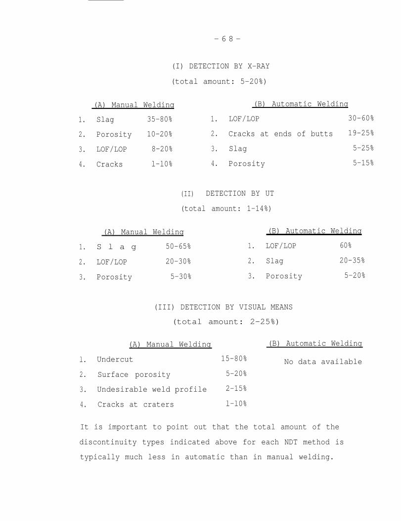
- 6 8 -
(I) DETECTION BY X-RAY
(total amount: 5-20%)
(A) Manual Weldinq
1. Slag 35-80% 1.
2. Porosity 10-20% 2.
3. LOF/LOP 8-20% 3.
4. Cracks l-l0% 4.
(B) Automatic Welding
LOF/LOP 30-60%
Cracks at ends of butts 19-25%
Slag 5-25%
Porosity 5-15%
(II) DETECTION BY UT
(total amount: 1-14%)
(A) Manual Weldinq
1. S l a g 50-65%
2. LOF/LOP 20-30%
3. Porosity 5-30%
(B) Automatic Weldinq
1. LOF/LOP 60%
2. Slag 20-35%
3. Porosity 5-20%
(III) DETECTION BY VISUAL MEANS
(total amount: 2-25%)
(A) Manual Welding
l. Undercut
2. Surface porosity
3. Undesirable weld profile
4. Cracks at craters
(B) Automatic Welding
15-80% No data available
5-20%
2-15%
l-l0%
It is important to point out that the total amount of the
discontinuity types indicated above for each NDT method is
typically much less in automatic than in manual welding.
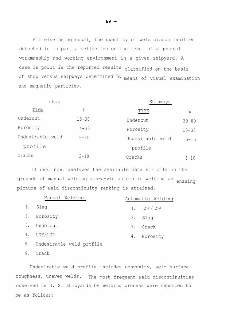
All else being equal, the quantity of weld discontinuities
detected is in part a reflection on the level of a general
workmanship and working environment in a given shipyard. A
case in point is the reported results
of shop versus shipways determined by
and magnetic particles.
shop
TYPE %
Undercut 15-30
Porosity 4-30
Undesirable weld 2-10
profile
Cracks 2-10
classified on the basis
means of visual examination
Shipways
TYPE %
Undercut 30-80
Porosity 10-30
Undesirable weld 5-15
profile
Cracks 5-10
If one, now, analyzes the available data strictly on the
grounds of manual welding vis-a-vis automatic welding an
picture of weld discontinuity ranking is attained.
Manual Weldinq Automatic Weldinq
1. Slag 1. LOF/LOP
2. Porosity 2. Slag
3. Undercut 3. Crack
4. LOF/LOP 4. Porosity
5. Undesirable weld profile
ensuing
6. Crack
Undesirable weld profile includes convexity, weld surface
roughness, uneven welds. The most frequent weld discontinuities
observed in U. S. shipyards by welding process were reported to
be as follows:
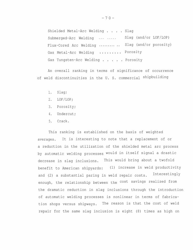
- 7 0 -
Shielded Metal-Arc Welding . . . . Slag
Submerged-Arc Welding
Flux-Cored Arc Welding
Gas Metal-Arc Welding
. . . . . . . . Slag (and/or LOF/LOP)
......... .. Slag (and/or porosity)
......... Porosity
Gas Tungsten-Arc Welding . . . . . Porosity
An overall ranking in terms of significance of occurrence
of weld discontinuities in the U. S. commercial
1. Slag;
2. LOF/LOP;
3. Porosity;
4. Undercut;
5. Crack.
shipbuilding
This ranking is established on the basis of weighted
averages. It is interesting to note that a replacement of or
a reduction in the utilization of the shielded metal arc process
by automatic welding processes would in itself signal a drastic
decrease in slag inclusions. This would bring about a twofold
benefit to American shipyards: (1) increase in weld productivity
and (2) a substantial paring in weld repair costs. Interestingly
enough, the relationship between the cost savings realized from
the dramatic reduction in slag inclusions through the introduction
of automatic welding processes is nonlinear in terms of fabrica-
tion shops versus shipways. The reason is that the cost of weld
repair for the same slag inclusion is eight (8) times as high on
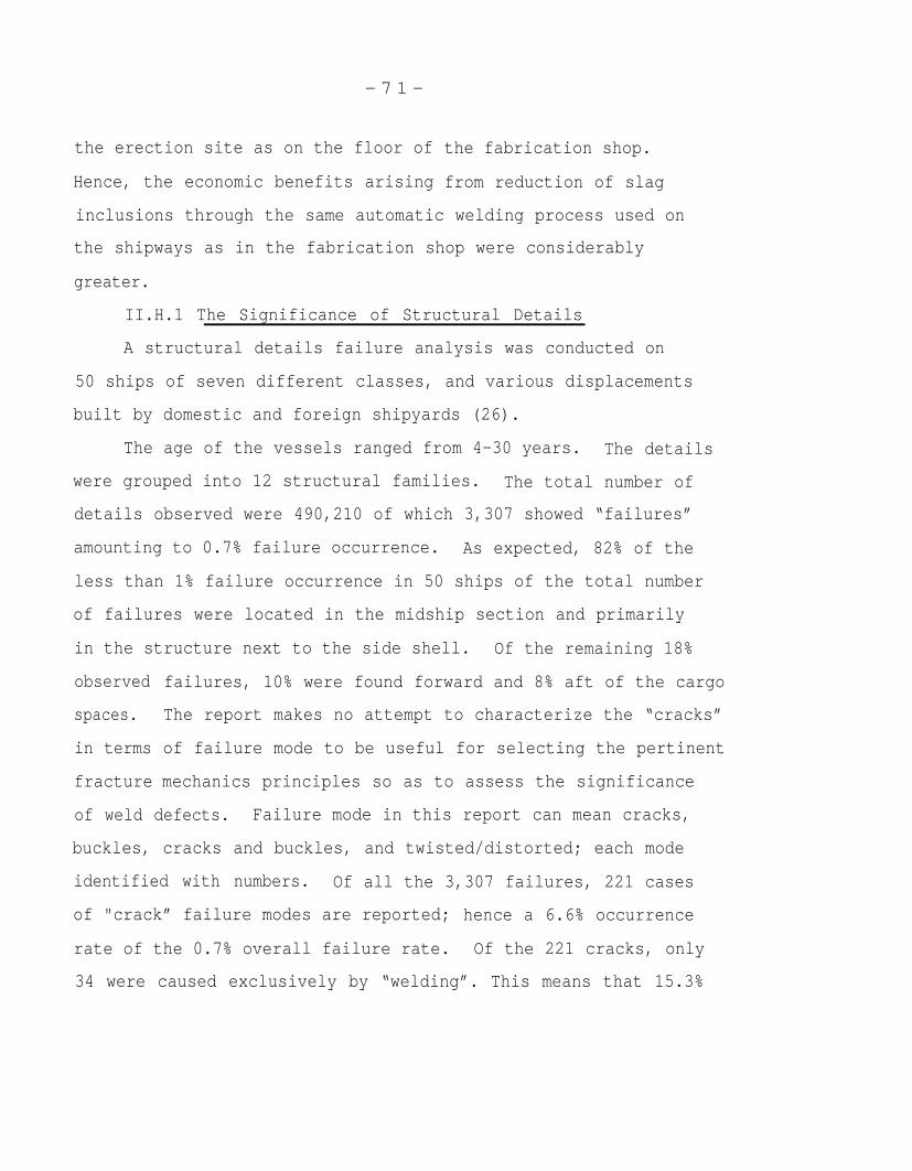
- 7 1 -
the erection site as on the floor of
Hence, the economic benefits arising
the fabrication shop.
from reduction of slag
inclusions through the same automatic welding process used on
the shipways as in the fabrication shop were considerably
greater.
II.H.1 The Significance of Structural Details
A structural details failure analysis was conducted on
50 ships of seven different classes, and various displacements
built by domestic and foreign shipyards (26).
The age of the vessels ranged from 4-30 years. The details
were grouped into 12 structural families. The total number of
details observed were 490,210 of which 3,307 showed “failures”
amounting to 0.7% failure occurrence. As expected, 82% of the
less than 1% failure occurrence in 50 ships of the total number
of failures were located in the midship section and primarily
in the structure next to the side shell. Of the remaining 18%
observed
spaces.
in terms
fracture
failures, 10% were found forward and 8% aft of the cargo
The report makes no attempt to characterize the “cracks”
of failure mode to be useful for selecting the pertinent
mechanics principles so as to assess the significance
of weld defects. Failure mode in this report can mean cracks,
buckles, cracks and buckles, and twisted/distorted; each mode
identified with numbers. Of all the 3,307 failures, 221 cases
of "crack” failure modes are reported; hence a 6.6% occurrence
rate of the 0.7% overall failure rate. Of the 221 cracks, only
34 were caused exclusively by “welding”. This means that 15.3%
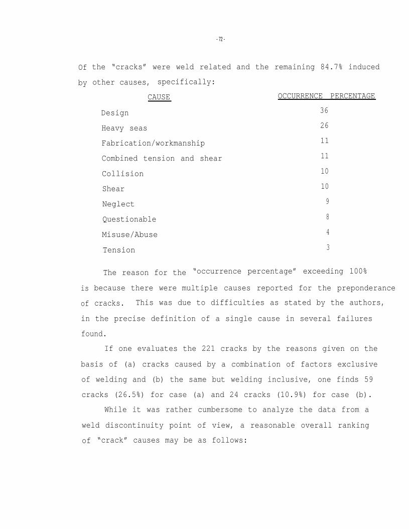
- 72 -
Of
by
is
of
the “cracks” were weld related and the remaining 84.7% induced
other causes, specifically:
CAUSE OCCURRENCE PERCENTAGE
Design 36
Heavy seas 26
Fabrication/workmanship 11
Combined tension and shear 11
Collision 10
Shear 10
Neglect 9
Questionable 8
Misuse/Abuse 4
Tension 3
The reason for the “occurrence percentage” exceeding 100%
because there were multiple causes reported for the preponderance
cracks. This was due to difficulties as stated by the authors,
in the precise definition of a single cause in several failures
found.
If one evaluates the 221 cracks by the reasons given on the
basis of (a) cracks caused by a combination of factors exclusive
of welding and (b) the same but welding inclusive, one finds 59
cracks (26.5%) for case (a) and 24 cracks (10.9%) for case (b).
While it was rather cumbersome to analyze the data from a
weld discontinuity point of view, a reasonable overall ranking
of “crack” causes may be as follows:
- 7 3 -
1.
2.
3.
4.
5.
6.
7.
8.
9.
10.
11.
12.
13.
Structural design;
Combination of factors exclusive of welding;
Heavy seas;
Welding;
Fabrication/workmanship;
Combined tension and shear;
Combination of factors inclusive of welding;
Collision;
Shear;
Neglect;
Questionable;
Misuse/abuse;
Tension.
Therefore, from a fatigue and fracture control standpoint
of a ship in-service, improvements in the structural design
details are considerably more important than an enhancement in
the inspection of welds and welding processes currently applied
in U. S. shipyards. In fact, the information presented in this
report suggests that there is a substantial incentive to
selectively relax existing weld acceptance standards.


- 7 4 -
been
II.I. Case History of Alyeska Oil Pipeline
The principles of fracture mechanics have in recent years
tested extensively. The most notable example in this regard
is the Trans-Alaska Oil Pipeline girth welds. The Alyeska crude
oil pipeline project represents - on a giant scale - the world's
first testimonial to the applicability of fracture mechanics
principles as a tool to assess the significance of weld defects
in girth welds. Because fracture mechanics principles were
successful in demonstrating the
existing code and made a change
thought appropriate to devote a
overconservative nature of an
in the code possible, it was
chapter to the discussion of
this important case history. Moreover, the very essence of this
famous case history was deemed apropos of the objective of this
project.
The original construction code applied to the pipeline was
API-1104 and the defect acceptance levels in it were established
to maintain a certain level of workmanship. But, it bore no
relationship to the performance of the pipeline in service (57).
The audit of 30,000 welds revealed discontinuities larger in
size than what was allowed by the relevant code in some 2,955
girth welds. The extensive tests conducted by the British
Welding Institute, Cranfield Institute of Technology, the
American National Bureau of Standards and Southwest Research
Institute showed that the weld defects and arc burns in question
“under the conditions of best estimates for criticality”
required no weld repair.
- 7 5 -
Among others, this case history included the testing of
three types of arc strikes, namely,
“touch” (arc time = 0.056 second)
"strike” (arc time = 0.158 second)
“drag" (electrode dragged across the full width
of the specimen at mid length)
“Touch” involving the lowest heat input gave the highest no break
transition temperature. This was presumably due to a high local
hardness giving rise to a low local toughness. However, all
three types of arc strikes yielded no break transition temperature
far below the minimum conceivable steel temperature in Alaska
(117). The chemistry of the pipeline steel manufactured by
Nippon Kokan KK is shown in Table I (l17).
Hydrogen induced stress corrosion cracking (SCC) can occur
at arc strikes under severe environmental, above-yield-stress
and high material hardness conditions. When the Alaskan pipeline
material was softer than 310 HV 2½ (=31 Rc), no SCC was observed
(118). Therefore, SCC at arc strikes would most likely terminate
in HAZ. SCC, even under the most severe environmental and stress
conditions, can occur only in materials whose hardness exceeds
250 HV (118). So, crack propagation by stress corrosion mechanism
into the parent steel is believed to be extremely improbable.
No stress corrosion was discovered in the weld metal of Alaskan
pipeline steel even in the presence of a weld discontinuity of
applied stresses above yield and under ambient conditions expected
on a historical basis in Alaska (118).
- 7 6 -
“Irregularities” detected on radiographs included:
1. LOF and LOP;
2. Slag inclusions;
3. Porosity;
4. Cracks;
5. Gas pockets;
6. Hollow weld beads;
7. Burn-through.
The largest number of repairs required by Code involved gas pockets
located mostly at the bottom of the pipe where welders ended their
weld (87). All these "irregularities” can be categorized using
fracture mechanics terminologies as planar, non-planar defects
and arc burns (45). The approach taken to assess whether these
discontinuities are deleterious or innocuous assumed worst-case
conditions. Specifically, all flaws were considered as surface
cracks. Furthermore, calculations were carried out on the basis
of minimum material toughness, maximum stress arising from high
hoop and tensile residual stress, pipeline loading and pressure,
earthquake, worst-case fatigue, most adverse service environment,
corrosivity, and temperature. The crack growth rate was assessed
under both cyclic and sustained load conditions. The net conclu-
sion according to the fitness-for-purpose criteria was that
larger flaws can be allowed than the API Standard 1104 had
permitted. So, DOT granted waivers for compliance with API-1104
and DOT accepted the principles of using a Yielding Fracture
Mechanics analysis to derive defect acceptance levels in a large
- 7 7 -
pipeline project (57, 60, 61, 119). Again, the uncertainties
were taken care of by assuming “worst-case-conditions” and by
including safety factors. The net effect of such assumptions
is a notable conservatism in the calculations. Nonetheless,
the conclusion proved that the standards applied to the construc-
tion of the Alyeska pipeline project was largely restrictive;
hence, punitive from the standpoint of weld defect repair
economics. The real paradox of the Alyeska pipeline case history
was, of course, that in spite of the finding approved by NBS,
that the discontinuities were innocuous and, despite the DOT
waiver, all the discontinuities in question were repaired at a
total cost of over $50 million.
- 7 8 -
III.
than
CONCLUSION
Fitness-for-purpose philosophy is considerably more rational
the present workmanship-based weld acceptance standards.
Fracture mechanics principles
assessing the significance of
aspects of fracture mechanics
state of
specific
types of
are a proven and useful tool in
weld defects. Although certain
are still under refinement, the
the art is sufficiently developed to begin to formulate
weld acceptance criteria with respect to the various
weld discontinuities: notably, slag inclusions and
porosity.
Increasing sophistication in inspection techniques makes
the development of rational weld acceptance standards all the
more important. Compatible with a new weld acceptance criteria,
there appears to be an optimum level of weld inspection beyond
which the benefits are no longer cost effective.
Existing standards are overconservative and do not address
the role of residual stress, “size effect”, interaction effect,
discontinuity location and shape differences. Fitness-for-purpose
philosophy should not be construed to mean a decrease in weldment
quality, rather an increase via outlining the conditions of
eliminating unnecessary weld
synonymous with an automatic
an ipso facto elimination of
repairs. Weld repair is neither
improvement in weldment quality nor
weld discontinuities.
The world literature shows a good agreement in that porosity
and slag inclusions are regarded to be least harmful of all weld
discontinuities. Ranking of weld discontinuities in descending
- 7 9 -
order of importance is as follows:
1. Cracks and crack-like defects.
2. Geometric discontinuities.
3. LOF/LOP.
4. Slag inclusions.
5. Porosity.
The predominant failure mcde in commercial vessels is fatigue.
The incidence of occurrence of brittle fracture is reported to
be very few. Therefore, the most important fracture mechanics
principle pertinent to merchant ships is the Paris formula:
Information on corrosion fatigue of ship steel weldments and role
of discontinuities in both low- and high-cycle fatigue is sparse.
Additional research in these areas is in order. Due to the
empirical nature of the treatment of fatigue, safety factors are
required to take care of uncertainties in determining the exact
magnitude of (a) stresses, (b) discontinuities,
geneities in shipbuilding steels and the welds,
the fracture toughness.
and (c) hetero-
which influence
LEFM has limited usefulness since brittle fracture seldom
occurs in commercial ship hulls according to the literature.
Structural design details and joint misalignment constitute
the principal causes of ship failures. Weld discontinuities are
reported to rank extremely low in causing failures in seagoing
commercial ships.

- 8 0 -
The majority of weld repair activity in U. S. shipyards
involves removal of slag inclusions and porosity. An estimatedsavings realized from minimizing weld repair of innocuous weld
discontinuities could range from $300,000 to well in excess of
$1 million per ship hull.
The “Quality Bands" approach to establishing more rational
standards for slag and porosity seems to have
in the international literature.
The new weld acceptance standards should
testing large-scale, full-thickness weldments
a broad support
be verified by
containing slag
inclusions and/or porosity. This experimental program ought
to be defined in detail by a Task Force group of experts
representing shipyards, classification societies, owner/operators
and design offices.
From a fatigue and fracture control point of view of an
ocean-going merchant ship the analysis of available data suggests
that first priority be given to improving design details and
decreasing joint misalignment. Since ship failures are induced
by a host of causes, the implementation of a “Quality Control
Systems Loop” founded on good feedback and total participation
proposes to be most essential and beneficial to the overall
improvement in the present state of the American shipbuilding
industry.
A Center should
building community.
be established for seining the American ship-
- 8 1 -
IV. RECOMMENDATIONS
The
of major
1.
One
of large
results of this study suggest, in four specific areas
interest, the following recommendations.
Ad Hoc Task Group
school of thought of failure analysis advocates the use
scale tests for assessing fatigue failure modes (25,
72-73, 90, 120). They believe that such test(s) are less tenuous
and more practical than the intricacies of fracture mechanics
principles involved in threading together the interacting effects
of crack blunting, strain hardening, crack closure, residual
stresses, exhaustion of ductility, the presence of multiple
defects of one or more species, micro-structural heterogeneities,
inaccuracies in load characterization, and all the possible
“second order effects”, necessary to permit a precise forecasting
of the in-service behavior of huge welded structures such as
ships. The difficulties in modelling all these second order
effects in what may constitute a series of mathematical formula-
tions have led to-a scatter in fatigue life results (73).
The suggestions to bring about changes in current standards
in general, noted in the world literature, have assumed many
forms. Bergemann (121) states that “full reliance on conventional
criteria
basis of
O‘Connor
sometimes leads to absolutely wrong conclusions”. The
his recommendations is the use of fracture mechanics.
proposed that revisions of existing codes could be
formulated in accordance
acceptance standards for
(122). Views on quality
with welding process used: "separate
full- and semi-automatic processes”
control of shipbuilding welds put forth
- 8 2 -
by Dr. Leide and his colleagues (123) are that ship structures
might be classified into four groups. The character and size
of tolerable defects in a particular ship component may not be
identical. An interesting observation voiced by Wyatt (124)
is “common sense, forethought and discipline have proved at
least as important as basic science and engineering technology”.
Howden (125) “predicts that defects acceptable
standards will cause problems in the future as
level of pipe steel is increased”.
by present day
the strength
Another proposal includes classification of welds into
three quality grades on the basis of fatigue or brittle fracture
conditions, type and severity of defects present, statically
loaded structures and lightly loaded welds (126). Whether the
load acting upon a particular weld defect present in a weld is
parallel with or normal to the joint is important in terms of
weld defect acceptance criteria. Having recognized this, less
stringent standards may suffice (127). Karsai, et al (128)
concluded from the model studies conducted on pipeline welds
that current Hungarian standards were overconservative, “excessive”.
A timely reassessment of relevant weld acceptance standards is
needed (1). Reasons given by Professor Lundin are that current
codes are for the most part too restrictive in few cases
unconservative and sufficient state of the art knowledge now
exists on the effects of weld discontinuities on service
performance of the weldments.
schutz and others feel (25, 129) that an approach
suited to predict fatigue life than fracture mechanics
better
would
- 8 3 -
be to use “realistic tests with real structures or components.
If this is not possible, use models or specimens”, as would
be the case for commercial ships, offshore structures.
To begin with, the test method must be standardized to
be able to correlate data obtained under different sets of
test conditions. The scoping and scaling of fatigue tests
are rightfully presumed to fall in the realm of responsibilities
of a Task Force Group of experts.
TFG may consist of representatives of shipbuilders, code
making bodies, owner/operators, Navy, U. S. Coast Guard and the
Maritime Administration to address this problem. They should
examine the degree to which existing weld acceptance standards
with respect to specific weld discontinuities ought to be
liberalized based upon a series of well conceived fatigue
tests conducted under worst-case conditions of commercial ship
environments (120). The Ad Hoc Group might consider for large .
scale fatigue testing two or three basic welding processes of
SMA, SA, and flux-cored arc, preferably for specific and most
important ship components. As test parameters, effects of sea
water
slag,
crack
environment, different load histories, various amounts of
porosity, lack of fusion, undercut, crack sizes, and
locations should be assessed. To shorten the evaluation
process, only variable amplitude load histories, different
frequencies of stress cycles involving various mean stress
levels should be investigated. It might be pointed out that
frequency of loading is reported to
presence of a corrosive environment
129-131). Assume 20 or 30 years as
be important only in the
such as sea water (22, 71,
the life of a ship. So,
- 8 4 -
the index of life or the number of cycles of fatigue should be
estimated on that basis. Each specific test should be repeated
enough times to establish a high level of confidence. After
that, set up charts for weld defect standards on the basis of
load levels and quality bands, easily useable by the practicing
inspectors in the shipyard (see examples in Appendix III).
It is worth remembering that over the years the quality of
steels and filler metals have undergone much improvement. As
a result, weldments of today have much greater tolerance for
discontinuities than those of the Liberty ships era. By and
large, specifications have not reflected this change. Rules
still rely heavily on old traditions, hearsay and fear (62).
Suffice it to say that existing standards ought to be modified
to take notice of these improvements in both the quality of
materials used and our contemporary understanding of weldment
behavior. When all is accomplished, ship quality shall be
better for it.
The practical translation of the meaning of fracture
mechanics on fatigue could take the form of “allowable defect
size curve” determined by the Task Group (7, 60). The National
Bureau of Standards’ approach (132) to these “curves” “will be
based on:
l.. applied stress levels
2. fracture toughness levels
3. defect size
All defects will be assumed as surface cracks. Such a scenario
appears too conservative for commerical ships because most of the
discontinuities found in welds are buried slag inclusions and
porosity.
- 8 5 -
For purposes of fracture mechanics calculations, the ship-
building steels may be grouped according to:
1. high fracture toughness
2. intermediate fracture toughness
by
an
3. low fracture toughness
The Task Force concept is not
definition. Pooling together a
umbrella of one kind or another
new, nor is it ever permanent
group of leading experts under
has often been used to implement
certain special tasks. The Pressure Vessel Research Committee in
its 1979-80 Annual Report mentions that the Subcommittee on
Elevated Temperature Design formed a Task Group on “international
benchmark problems”. One of the Group’s objectives involves the
“development of acceptance criteria for weld defects in elevated
temperature service to assist the ASME Boiler and Pressure
Vessel Code” in this endeavor (89). This is a modest indication
that the efforts of many years of research and test expended
internationally on the significance of weld defects is beginning
to pay off in bringing about changes needed in existing codes.
Code-making bodies for shipbuilding should follow suit.
2. Information Center
Improvements in product performance come from comprehensive
assessment of technologies and data available. The confidence
level of the conclusions deduced depend to a very large extent
upon the size of the data bank and the degree of accuracy with
which it has been acquired. Information gathering ought to be
systematic, continuous and all-encompassing. Studies such as
the one conducted by C. R. Jordan and C. S. Cochran of Newport
News Shipbuilding are extremely beneficial in providing “feed-back”
- 8 6 -
data to the engineer and designer who develops a design and
never receives the performance data that is needed for future
improvements, growth and increased confidence (26].
Another important observation they point up in their report
is that "orderly and systematic study of structural details on
ships in service can make a significant contribution to design
and repair knowledge that should result in an improvement in
design and fabrication practices and increase the number of
sound details in present and future ships”. In their Part
continuation report, a survey was conducted on the midship
section of thirty-six ships: twelve bulk carriers, twelve
container ships and twelve general cargo ships (27). This
II
survey reconfirmed many of the failure trends established in
the first fifty ship survey. However, distinctive service
performances were identified in the second survey. The data
from the two surveys were summed up to make all this information
readily accessible to interested personnel. The highlight of
the overall conclusion is that failures are attributed to “one
or a combination of five categories: design, fabrication,
welding, maintenance and operation” (27).
A task of this magnitude is certainly too large and
expensive to be supported solely by any individual shipyard.
Even if a single, enterprising yard would attempt to set out
on a project like this, it would take too long to compile an
adequate data bank. As Messrs. Jordan and Cochran put it,
“Projects of this type should be a continuing effort. As more
ships are surveyed, there is less need for estimated data as
- 8 7 -
used in the first survey. Eventually, a substantial data base
is formed from which meaningful statistical analyses can be
conducted to provide useful information to ship owners as well
as design offices.” A typical example to a ship owner/operator
and a design office might be a better assessment of ship
maintenance economics and selection of improved detail configura-
tion suitable for a specific design situation, respectively. A
valuable feedback to a shipbuilder might, on the other hand, be
a well-defined welding parameter or defect having contributed
to a specific failure mode. This knowledge should pre-empt the
same problem from re-occurring in the future in identical situations.
The Center may wish to consider the statistical approach to
determining the relationship of type, size, and amount of weld
defects to causing frequency of specific failure modes in
specific welds and weldments. A correlation between the original
inspection data and the service performance of the inspected
welds irrespective of the presence or absence of discontinuities
would be most fruitful. Today this sort of a correlation is not
done. We do not know how the inspected joints fair in service.
On this, there is no feedback to the QA or QC Department. In
the present system of quality assurance, the only time information
is supplied from the field
system of information flow
or not the data represents
is if there is a failure. The present
does hot as a rule identify whether
originally inspected or noninspected
weldment sites. A system is good if it
correlations thereby ultimately leading
of:
lends itself to clear-cut
to better characterization
- 8 8 -
1. Usefulness of inspection methodologies.
2. Weld defect acceptance standards.
3. Direction in which to proceed to augment the
level of confidence in the total system and
attainment of optimum weld acceptance standards.
Synthesis of data and information yields definitive cause-
and-effect relationship, pinpointed areas of improvement,
reduced weld repair costs and improved product quality. such
an approach minimizes guessing.
Establishment of a
building Industry could
might best be viewed as
Center for serving the American Ship-
turn out to be a noble idea. The Center
a mechanism for disseminating information
of what its voluntary membership would deem economically and
technologically productive; e.g., periodic reassessments of
weld defect and design standards, information storage and
retrieval, trainingf etc. (133).
While there are various committees entrusted to carry out
certain responsibilities, there is now no satisfactory vehicle
in the U. S. shipbuilding industry to coordinate, monitor,
analyze, disseminate statistical data, information and enhanced
knowledge not only in the art of welding but in other relevant
engineering disciplines on a concerted, ongoing basis and in
sufficient depth. It is in the interest of everyone that we
create a good line of communication among shipbuilders, materials
producers, classification
operators with respect to
societies, design firms, and owner/
our best understanding on the real role
- 8 9 -
of weld discontinuities and growing experience. In such a
climate, one does not become an inflexible guardian of the
status quo.
The economic consequences of occasional defects or local
structural problems induce shipyards to impose high standards
of quality often times independent of relevant classification
societies (3). This is a commendable act. However, it tends
to mean
actions
3.
In
that one needs first a disaster before appropriate
are taken.
Quality Control Systems Loop
a large and complex industrial environment a great deal
of the inspection effort goes into determining the cause of
sudden loss of quality or of diminishing workmanship. The
Quality Control Systems Loop (QCSL) advocated can be an inexpen-
sive answer to that problem.
Important elements of this quality control systems loop
would be:
a.
b.
c.
Quality planning by quality control department
together with appropriate engineering and
production personnel.
Appraisal of the plan by process control
engineering persons to check the compliance
of the plan with relevant standards.
Feedback of data and analysis thereof by
process control engineering, manufacturing
or production departments in order to determine
the need for possible changes, new planning,
corrective actions.
- 9 0 -
d.
e.
The
Continuous audit of QC plan to ensure satisfactory
workmanship, conformance.
Upkeep of training and teaching people about the
vital role of an all-encompassing quality control
systems approach, which serves everyone’s interest.
reader is referred to Appendix I showing the schematic
of the Quality Control Systems Loop. The implementation of such
a system requires time. Its effectiveness will be a function of
the degree of participation and the nature of the attitudes of
the participants. If QCSL is properly formulated and implemented
by the total work force of a given shipyard it should unquestion-
ably be less costly and far more efficacious of a tool to achieve
the desired objective than that through the hiring of more inspec-
tors or more NDT methods. After all, the affordable cost of QC
inspectors and NDT methodologies is finite. It is more so in
times of austerity in a given industry than when that industry
enjoys an economic prosperity. Certainly, the shipbuilding
industry has of late been in the former economic state. Let us
face it; ultimately, quality control and its guarantee are in
the hands of the people who build the product and not in mere
policing the rules of the game, or writing standards. This
philosophy does not intend to ignore the proper share of “formal
inspection” and the application of NDT methods and instrumentations.
The QCSL is predicated upon setting up a proper balance of all
proposed QCSL, the U.S. Navy and
system. Analogous to the
Air Force started to use sometime
- 9 1 -
ago the so-called “Fracture and Fatigue Control Plan” (134-135)
or “Flaw Tolerance Control Plan” (136-137). The Plan has a
Fracture and Fatigue Control Board headed by the Chairman who
reports directly to the President [e.g., of Lockheed Aircraft
Company (134)]. Reporting to the Fr.F.C.B. Chairman are the
following functions along the QC or QA framework: testing,
material analysis, welding, manufacturing, procedures, drawings,
qualifications
demonstration,
facilities and
and certification of personnel, reliability
NDT parts plan, materials and parts classifications,
equipment conditions, maintenance, education and
training of personnel.
Factors affecting acceptance criteria and quality include
not only considerations for standards, specific agreements,
notion of fitness-for-purpose, but also for type and scale of
accepted practice and continued education of welders, supervisors,
inspectors, welding engineers, designers, managers and others
(138).
It is not
centralized or
the total plan
system. As of
so important whether the systems approach is
decentralized as that all the ingredients of
are integrated to ensure the success of the
1975, Japan used
Europe tended toward the use of
exception was Sweden). Lately,
has begun to increase along the
(104).
the decentralized approach, while
the centralized system (a notable
participation of the workers
lines of the Japanese system
Engineering materials, components and structures are not
perfect. They contain numerous material flaws, manufacturing
- 9 2 -
defects and design discontinuities. In view of such well. estab-
lished facts, it is inappropriate to presume that a structure
will fail as a consequence of diverse discontinuities inadvertently
introduced. More properly the fatigue and fracture control of
built structures should be approached by means of statistics.
In other words, how many, how large discontinuities may be
present and whereabouts in the structure do they lie. Are these
defects located in a highly stressed or in a non-load bearing
component of the engineered structure? Is the discontinuity
benign or detrimental to the performance of the weldment under
the loading condition and service environment anticipated?
Considerations should also be given to the propensity of the
component for premature failure which could arise from a whole
host of contributory factors. Unfortunately, information on
the distribution of discontinuities is rare (5).
Statistical data gathering is not easy, but is a very useful
task. Since the parameters used to carry out fracture mechanics
calculations are random variables - if for no other reason than
the inherent heterogeneity in the microstructure of materials.
The probabilistic fracture mechanics approach would be helpful
to establish a range for the respective variables: hence, a
greater reliability of predicting the ultimate behavior of-the
structure.
Keeping in-process records that are comprehensive enough in
an engineering and statistical sense can take on a rather emotional
aspect. However, documentation of comprehensive data is a must
- 9 3 -
if we are to eliminate repetitive errors. Good record keeping
is a foundation of evaluation: identification of problems,
detection, correction, prevention of defects, reoccurrence of
manufacturing faults, dimensional controls, misalignments, fit-up
problems, structural design details, etc. Along with others
(39, 101, 139-140), Volchenko (141) advocates the importance of
“statistical control of the technological process”. Konkoly
(142) did a quantitative evaluation of the effect of weld defects
upon the susceptibility of steels to brittle fracture. So, the
importance of data compilation has been well recognized in the
international literature. The probabilistic fracture mechanics
approach to shipbuilding weld
uncertainties associated with
structures.
An extremely significant
standards is quite real due to more
seagoing vessels than land-based
benefit that springs from QCSL is
an early awareness of the occurrence of weld defects and other
discontinuities in the process cycle of material and product
flow. The present “formal inspection system” lends itself to
discontinuity accumulation giving rise to excessive repair costs.
QCSL is like an early warning system for discontinuity acceptance
standards observed by all the participants during fabrication
as well as in service. It leads to elimination of repetitive
defects. QCSL is, by its very nature, an evolutionary procedure.
Nevertheless, it will eventually be self-policing and self-regulatory
without resorting to additional inspectors to impel improvements
in the entire system.
- 9 4 -
The practice of quality control must not be viewed by ship-
yard management as an isolated entity or as a privilege of a
designated few, but a part and parcel of the total system.
Considerations given to a part of the system invariably does bear
upon other segments of the very same system. A good illustration
of this point would be to single out the strong relationship
between accuracy - better known as “fit up” in the shipbuilding
industry - and quality control. Accuracy has to do with technology;
inter alia, jigs, tools, modern up-to-date equipment to attain a
good fit-up. Quality control on the other hand means the achieve-
ment of an acceptable workmanship in accordance with a certain
set of requirements. Accuracy in the prefabircation stage is
needed in order to insure a satisfactory quality level. Fit-up
will influence weld quality (104). In the absence-of available
accuracy, a satisfactory quality control level cannot be achieved
without
It
able to
will in
problem
it then
severe manufacturing cost penalties.
is necessary to compile quality control data so as to be
establish tolerance limits. The analysis of the data
turn permit the defining of quality trends or ranking of
areas. Once these trends or problem areas are determined
becomes considerably easier to delineate the course(s)
of corrective action(s). Phillip (104) makes the suggestion that
the quality of workmanship and dimensional accuracy be checked
right from the start of building a ship, at prespecified stages
during fabrication and erection. Competition among shipyards
of the world does not allow room for inferior quality (104).
The dictates of economics and competition engenders what may be
- 9 5 -
called "The System Approachw to quality control rooted in a
continuous feedback.
The Japanese approach to quality control is, “Produce better
quality products by performing proper work according to the
Standards. Eliminate defects before they occur” (39). According
to Kobayashi, the QC system is set up on the basis of:
a. Statistical methods
b. Self-quality checks by the workers
The latter helps promote morale among the workers, for they
feel they are an integral part of the total system. A greater
awareness of the importance of quality workmanship on the part
of the work force eventually leads not to the hiring of more
inspectors, rather the reduction in the cost of inspection and
amount of repair. A natural consequence of total participation
is an enhancement of the level of quality of the entire system
without an accompanying rise in the cost of quality control.
Undoubtedly, this
education or even
The Japanese
peers not only to
is a developmental process. It requires
re-education is some cases.
seem to pay more attention than their American
the final inspection and to the workers’
morale in the maintenance of
quality control as well. In
used as illustrations in the
good quality, but to the in-process
Japan the results of inspection are
continued education of welders.
Despite voluminous publications all
written over the decades by an awesomely
scientists, engineers, technologists and
throughout the world
impressive array of
others, the acceptance
- 9 6 -
of fracture mechanics has shown a very slow progress. why?--
It is in the aggregate interest of the academic, research,
industrial and code making communities to unravel the answer.
Perhaps a world conference held for this purpose and in which
universities,
societies and
in sufficient
a cornerstone
that too much
research institutions, industry, classification
users of welded products would be drawn together
numbers might turn out to be a decisive forum and
event. We just might find out in such a gathering
information has been left laying scattered in too
many of the world’s publications: hence, its desired effects
fragmented and full impressions inadequately realized by all
concerned. No doubt, a few arguments and travails would be
generated, but it is hoped that from them would come a better
understanding for designers, metallurgists, welding engineers,
inspectors and surveyors.
4. Proposed Weld Acceptance Standards
The statistical analysis of available quality control data
and information showed that the preponderance of weld repair
activity
industry
proposed
in the commercial sector of the U.S. shipbuilding
involved slag inclusions and porosity. It is, therefore,
that first priority be given to the establishment of
new, improved weld acceptance standards with regard to said weld
discontinuities. Most of the savings - solely in terms of weld
discontinuities - would come from minimizing unnecessary weld
repair due to slag inclusions and porosity. Moreover, said weld
discontinuities constitute the least harmful of all weld defects
recognized by the world literature.
- 9 7 -
In terms of relaxation of existing weld acceptance standards
for slag inclusions and porosity, the exemplary format of proposed
standards - shown in Appendix III - may be used as a point of
departure for reassessment by a commissioned Ad Hoc Task Group.
In fact, each specific point in all of the recommendations
mentioned is intended merely as a suggestion. It is up to the
judgements and best discretions of the Task Force to deal with
specific engineering details, priorities and cost-, duration-,
and quantity-of tests.
- 9 8 -
ACKNOWLEDGEMENT
Sun Ship, Inc. wishes to express its appreciation to Bath
Iron Works for awarding this subcontract and the U. S. Maritime
Administration for sponsorship. The author is pleased to recog-
nize the helpful discussions and comments made by Dr. John D.
Harrison, The Welding Institute, Cambridge, UK, and Professor
Carl D. Lundin, University of Tennessee, Knoxville, Tennessee,
USA, for reviewing the manuscript. Special “thanks” are extended
to the many experts in several U. S. shipyards and the American
Bureau of Shipping for the supply of quality control data and the
forthright exchange of views.
I am ”particularly grateful to two of my colleagues at Sun;
Dr. Richard T. Bicicchi for guidance and encouragement throughout
this study and Mr. Thomas P. Krehnbrink for valuable comments on
the manuscript. Mrs. Denise Cacciatore deserves recognition for
her diligence in typing the report.
- 9 9 -
REFERENCES
1.
2.
3.
4.
5.
6.
7.
8.
9.
10.
11.
12.
Lundin, C. D., “The Significance of Weld Discontinuities -A Review of Current Literature, ” WRC Bulletin #222,December 1976.
Basar, N. S., et al, “Survey of Structural Tolerances inthe United States Commercial Shipbuilding Industry, ”M. Rosenblatt and Son, Inc. , SSC-273, 1978.
Santini, W., “Quality Standards and Quality Control inShipbuilding: A Joint Task of Shipyard and ClassificationSociety," Paper 29, International Conference, London,November 18-20, 1975, Vol. 1, TWI, Cambridge, 1976.
Harrison, J. D., et al, “The Acceptability of Weld Defects,”The Royal Institution of Naval Architects, Spring Meetings,1974.
Harrison, J. D., “Application of Fracture Mechanics in thePrevention of Service Failures," The 3rd National Symposiumof the Japan Welding Society, September 1978, Tokyo.
Gurney, T. R., “Theoretical Analysis of the Influence ofToe Defects on the Fatigue Strength of Fillet Welded Joints,”TWI Research Report, 32/1977/E, March 1977.
WRC Progress Reports, Vol. XXXII, No. 11 (Nov. 1977), NO. 12(Dec. 1977), Vol. XXXIII, No. 4 (April 1978), Vol. XXXIIINo. 5 (May 1978), No. 7 (July 1978), NO. 10 (Oct. 1978).
Screm, G., et al, “The Effect of Weld Defects in Reducingthe Fatigue Strength of Welded Joints,” Alluminio, Vol. 44,No. 3, March 1975.
Bailey, N. and Miss “David, M.L.E., “Fluxes for submergedArc Welding Ferritic Steels - A Literature Survey,” Part 2:Weld Properties and Weld Defects, TWI Research Report,10/1976/M, May 1976.
Boulton, C. F., “The Influence of Surface Porosity on theFatigue Strength of Butt Welded Joints”, TWI ResearchBulletin, Vol. 18, No. 2, February 1977, pp. 41-45.
Harrison/ J. D., et al, “A Re-analysis of Fatigue Data forButt Welded Specimens Containing Slag Inclusions,” TWIResearch Report #37/1977/E, April 1977.
British Standards Institution, “Draft PD for Guidance onSome Methods for the Derivation of Acceptance Levels forDefects in Fusion Welded Joints,” London, June 1978.
- 100 -
13.
14.
15.
16.
17.
18.
19.
20•
21.
22.
23.
24.
Harrison, J. D., “Basis for a Proposed Acceptance Standardfor Weld Defects. Part II: Slag Inclusions, ” MetalConstruction and British Welding Journal, Vol. 4, No. 7,July 1972.
Boulton, C. F., “Acceptance Levels of Weld Defects forFatigue Service,” Welding Research Supplement, WeldingJournal, January, 1977.
Nichols, R. W., “Interrelationships between MechanicalProperties and the Significance of Defects,” Proceedings,Second International Conference on Pressure VesselTechnology, San Antonio, Texas, October 1-4, 1973, ASME,1974.
Harrison, J. D., “The Effect of Herringbone Porosity onthe Fatigue Strength of Butt Welds,” TWI Research Bulletin,Volume 18, No. 7, July 1977, pp. 175-178.
Thielsch, H., “The Sense and Nonsense of Weld Defects,”Monticello Books, Chicago Ill., 1967.
Soete, W., et al, “Influence of Weld Defects on High-FatigueBehavior,” Pressure Vessel Technology II - Materials andFabrication, First International Conference, sponsored byASME and Koninklijk Instituut van Ingenieurs, September 29-October 2, 1979, Delft, The Netherlands, New York, 1969.
Burdekin, F. M. et al, “The Effect of Weld Defects withSpecial Reference to BWRA Research,” Welding ResearchAbroad, Vol. 14, No. 7, August/September 1968.
Harrison, J. D., “Basis for a Proposed Acceptance Standardfor Weld Defects. Part 1: Porosity," Hetal Constructionand British Welding Journal, Vol. 4, No. 3, March 1972,
Ishii, Y., et al, “An Analysis of Intermediate Cycle Fatigueof Defective Welded Joints,” Transactions of the JapanWelding Society, Vol. 3, No. 2, September 1972.
Nibbering, J. J. W., et al, “Some Considerations for Fracture-Safe Design of Maritime Structures,” Integrity of OffshoreStructures, International Symposium, April 6-7, 1978, Glasgow,Scotland.
Knight, J. W., “Corrosion Fatigue of Steel Structures inSea Water,” TWI Research Bulletin, Vol. 17, No. 4, April1976, pp. 91-94.
Irving, R. R., “Will Code Bodies Accept Fitness for Purpose?”Iron Age, September 11, 1978.
- 101 -
25.
26.
27.
28.
29.
30.
31.
32.
33.
34.
35.
Schutz, w., “The Prediction of Fatigue Life in the CrackInitiation and Propagation Stages - A State of the ArtSurvey, ” Integrity of Offshore Structures, InternationalSymposium, April 6-7, 1978, Glasgow, Scotland.
Jordan, C. R., et al, “In-Service Performance of StructuralDetails,” Newport News Shipbuilding, Contract #NOO024-76-C-4362, U. S. Coast Guard, Washington, D.C., 1978.
Jordan, C. R., et al, “Structural Details Failure Survey,Part II,” Newport News Shipbuilding, Contract No. DOT-CG-75172-4, U. S. Coast Guard, Washington, May 1979.
Harrison, J. D., “The Application of Fracture Mechanics toWelded Structures,” Seminar on Use of Fracture Mechanics toAssess Weldment Reliability, Washington University, St. Louis,Missouri, October 26, 1978.
“Use of Fracture Mechanics to Assess Weldment Reliability.”Seminar Held at Washington University, St. Louis, Missouri,October 26, 1978, by The Center for Fracture Mechanics andThe Welding Institute. Lecturers: Drs. A. A. Wells,J. D. Harrison, Professors P. C. Paris, C. E. Turner, andG. R. Irwin.
Dolby, R. E., “HAZ Toughness of Structural and PressureVessel Steels - Improvement and Prediction, ” Welding Journal,August 1979.
Kikuta, Y., et al, “A Study on Microstructure and Precipitatein HAZ and Reheated Zone of Weld Metal of Structural Steel," Criteria for Preventing Service Failure in Welded Structures,Proceedings, 3rd International Symposium of the Japan WeldingSociety, Tokyo, September 26-28, 1978.
Bernard, G., “A Viewpoint on the Weldability of Carbon-Manganese and Microalloyed Structural Steels,“ Microalloying75 Proceedings, Union Carbide Corp., 1977.
Jesseman, R. J., et al, “Influence of Some SteelmakingVariables on Ship Plate Weldment Toughness, ” Welding Journal,August 1979.
Once, H., et al, “Japanese LPG Tanker Constructed Using aNew Welding Process and Improved Al-Killed Steels, ” MetalConstruction 11 (1), 1979.
Hannerz, N. E., “Effect of Stress Relieving Heat Treatmenton the Toughness Properties of Simulated HAZ’s in V-AlloyedSteels, ” Schweissen and Schneiden, 28 (10), 1976.
- 102 -
36. Once, Y., et al, “Improvement in Steel Properties by SulphideShape Control, ” Trends in Steels and Consumables for Welding,International Conference by the Welding Institute, London,November, 1978.
37. Pisarski, H. G., “Influence of Thickness on Critical CrackOpening Displacement (COD) and J Values," TWI ResearchReport, 90/1979, May 1979.
38. Winn, W. H., “Quality Assurance in Welded Ship StructuresDesigned on a Limited Budget, ” Paper 27, InternationalConference, London, November 18-20, 1975, Vol. I, TWI,Cambridge, 1976.
39. Kobayashi, K., “Quality Control in Shipbuilding, ” Paper 28,International Conference, London, November 19-20, 1975,Vol. I, TWI, Cambridge, 1976.
40. Walter, J. C., et al, “New Trends in the Application andEvaluation of Non-Destructive Testing, ” InternationalConference on Quality Control and Nondestructive Testingin Welding, London, November 19-21, 1974, The WeldingInstitute, 1974.
41. "Welding in the World, ” Vol. 15, No. 9/10, 1977.
42. WRC Progress Reports, Vol. XXXIV, No. 10, pp. 40-41,October, 1979.
43. The Welding Institute, “Significance of Weld Defects, ”Weldasearch System 2 and Literature Abstracts from 1967-1978.
44. Hertzberg, R. W., “Deformation and Fracture Mechanics ofEngineering Materials, ” John Wiley and Sons, New York, 1976.
45. Reed, R. P., et al, “A Fracture Mechanics Evaluation ofFlaws in Pipeline Girth Welds, ” WRC Bulletin #245, January,1979.
46. Dawes, M. G., “Contemporary Measurements of Weld MetalFracture Toughness, ” Welding Journal, December, 1976.
47. Davidson, D. L., et al, “Crack Tip Plasticity Associatedwith Corrosion Assisted Fatigue,” Southwest Research Institute#02-4268 for Office of Naval Research NRO-36-109/2-25-76 (471).,May 31, 1978.
48. WRC Long-Range Planning Committee, Department of CommerceTechnology Program, WRC Progress Reports Vol. XXXIV, No. 1,January 1979.
49. Trans-Alaska Crude Oil Pipeline, Petition for Waiver ofGirth. Weld Defects at the Valdez Terminal, Docket No. 77-9W,Federal Register, Vol. 44, No. 28, Thursday, February 8, 1979.
- 103 -
50.
51.
52.
53.
54.
55.
56.
57.
58.
59.
60.
61.
Doverr W. D., et al, “A Fracture Mechanics Analysis of theFatigue Failure of T-Joints Subject to Random Loading, ”Integrity of Offshore Structure, International Symposium,April 6-7, 1978, Glasgow, Scotland.
McEvily, Jr. , A. J., “The Fracture Mechanics Approach toFatigue, ” Significance of Defects in Welded Structures,Proceedings of the Japan-U. S. Seminar, 1973, Tokyo,University of Tokyo Press, 1974.
Irwin, G. R., et al, “Summary of Fracture MechanicsConcepts, ” Seminar on Use of Fracture Mechanics to AssessWeldment Reliability, Washington University, St. Louis,Missouri, October 26, 1978.
Wells, A. A., “Background to the Fracture Mechanics Approachto Fracture Control of Weldments, ” Seminar on Use of FractureMechanics to Assess Weldment Reliability, Washington University,St. Louis, Missouri, October 26, 1978,
Turner, C. E., “Fracture Toughness: Material Behavior andTest Procedures, ” Seminar on Use of Fracture Mechanics toAssess Weldment Reliability, Washington University, St. Louis,Missouri, October 26, 1978.
Paris, P. C., “Elastic-Plastic Fracture Mechanics Fundamentals,“Seminar on Use of Fracture Mechanics to Assess Weldment Relia-bility, Washington University, St. Louis, Missouri, October 26,1978.
Dawes, M. G., “Elastic Plastic Fracture Toughness Based onThe COD and J Contour Integral Concepts, ” TWI ResearchReport #54/1978/E, January 1978.
Harrison, J. D., et al, "The COD Approach and Its Applicationto Welded Structures, ” TWI Research Report #55/1978/E,January 1978.
Kobayashi, A. A., “Experimental Techniques in FractureMechanics, ” No. 1, 1973, No. 2, 1975, SESA.
Paris, P. C., “Fracture Mechanics in the Elastic-PlasticRegime, ” ASTM Publication 631, 1977.
National Bureau of Standards, “Consideration of FractureMechanics Analysis and Defect Dimension Measurement Assessmentfor The Trans-Alaska Oil Pipeline Girth Welds, Vols. 1 and 2,PB-260400, PB-260401, Washington, D. C., October 1976.
The Oil and Gas Journal,1976 on Alyeska pipelineand waver requests.
a series of articles published inweld flaws, inspections, repairs,
- 104 -
62. Harrison, J. D., “The Welding Institute Studies theSignificance of Alyeska Pipeline Defects," TWI ResearchBulletin, Vol. 18, No. 4, April 1977, pp. 93-95.
63. Bosworth, T. J., “The Application of Fracture Mechanicsto Weld Quality Control - A Concept, ” The Boeing Company,Paper presented at AWS Annual Meeting, Cleveland, Ohio,April 20-24, 1970.
65. Gurney, T. R., “Theoretical Analysis of the Influenceof Attachment Size on the Fatigue Strength of TransverseNon-Load-Carrying Fillet Welds, ” TWI Research Report #91/1979,May 1979.
66. Wilkowski, G. M., et al, “Review of Fracture MechanicsApproaches to Defining Critical Size Girth Weld Disconti-nuities, ” WRC Bulletin #239, ISSN 0043-2326, July 1978.
67. Draft British Standard - “Methods for Crack OpeningDisplacement (COD) Testing,” Private Circulation, Sub-Committee ISE/NFE/4/4, February 1978.
68. “Dynamic Fracture Toughness," International Conference byThe Welding Institute and The American Society for Metals,London, July 5-7, 1976.
69. Thaulow, C., “Comparison Between COD and Charpy Results onC-Mn Steel Weld Metal,” Metal Construction, The Journal ofthe Welding Institute, December 1978.
70. Irving, R. R., “New Energy Needs Test Welding's Mettle ,"Iron Age, December 12, 1977.
71. Francis, P. H., et al, “Subcritical Crack Growth and ShipStructural Design, ” Marine Technology, Vol. 13, No. 2,April 1976.
72. Gurney, T. R., Discussion of Professor Nibbering's papergiven at International Symposium on "Integrity of OffshoreStructures, April 6-7, 1978, Glasgow, Scotland.
73. Turner, C. E., Ibid.
74. “Criteria for Preventing Semite Failure in Welded Structures,”3rd International Symposium of the Japan Welding Society,September 26-28, 1978, Tokyo.
75.
76.
77.
78.
79.
80.
81.
82.
83.
84.
85.
86.
of the Navy, NavalNOO024-72-C--5316,
May, R. A., et al,Strength Steels in1978.
Ship Engineering Center, Contract No.Washington, D. C., 1974.
“Effective Utilization of High-YieldFatigue, ” WRC Bulletin #243, November
Sanders, Jr., W. W., et al,Aluminum Alloy Weldments in#242, October 1978.
“Fatigue Behavior ofMarine Environment, ”
5000 SeriesWRC Bulletin
87.
88.
89.
90.
91.
92.
93.
94.
95.
96.
97.
98.
99.
- 106 -
Burk, J. D., et al, “Effects of Lack-of-Penetration andLack-of-Fusion on the Fatigue Properties of 5083 AluminumAlloy Welds,” WRC Bulletin #234, January 1978.
Dorn, L. et al, “The Influence of Welding Defects onBrittle Fracture Behavior in Arc Welding” DVS Berichte,No. 45, Proceedings, SLV Berlin Jubilee Conference,Occupational safety, Quality control Thermal cutting,Berlin, May 11-13, 1977, published: Dusseldorf, DeutseherVerlagfur Schweisstechnik, 1977.
Pressure Vessel Research Committee, 1979-80 Annual Report.
Christopher, P. R., "Fatigue and Fracture in Relation toFabrication of Structures, ” Integrity of Offshore Structures,International Symposium, April 6-7, 1978, Glasgow, Scotland.
Miyoshi, S., “Detectable Weld Defects by Current NDT Code, ”Seminar on Significance of Defects in Welded Structures,Tokyo, October 15-19, 1973, published by University ofTokyo Press, 1974.
Ship Structure Committee, 1977, “A Guide for Interpretationof Nondestructive Tests of Ordinary-Medium- and High StrengthLow-A1loy Steel Butt-Joint Weldments in Ship Hull Structures, ”SSC-245.
“Rules” for Nondestructive Inspection of Hull Welds, ” AmericanBureau of Shipping, 1975.
Hennison, J., “Examples of Nondestructive Testing of VeryThick Welds on Pressure Vessels, ” Soudage et TechniquesConnexes, Vol. 26, No. 11-12, November-December 1972.
Kucera, J., "Admissible Defects in Welded Turbine Rotors}”Strojirenstvi, Vol. 22, No. 3, 1972.
Frederick, G., et al, “Reflections on the Significance ofDefects Observed by Ultrasonic Methods, in the Light ofFracture Mechanics, ” Revue de la Soudure/Lastijdschrift,Vol. 28, No. 1, 1972.
“Significance of Defects in Welded Structures, ” Proceedingsof the Japan - U. S. Seminar, 1973, Tokyo, University ofTokyo Press, 1974.
Fisher, J. W., et al, “Design, Structural Details andDiscontinuities in Steel,“ Proceedings, ASCE Conference,“Safety and Reliability of Metal Structure, n Pittsburgh,PA, November 2-3, 1972, published by ASCE, 1972.
DeSantis, R., et al, “Ultrasonic Control Procedures inPressure Vessels Fabrication. The Interdependence ofAcceptance Standards for Thick Plate and Welds ,” MetallurgiaItalia, Vol. 69, No. 3, March 1977•
- 107 -
100.
101.
102.
103.
104.
105.
106.
107.
108.
109.
110.
111.
112.
Tenge, P., et al, "Acceptance Criteria for Weld Defectsand Non-Destructive Inspection Procedures for LNG Tanksin Ships, ” Metal Construction, Vol. 7, No. 1, January1975.
Kazinczy, F. de, “Possibilities of Using Non-DestructiveTesting to Evaluate Critical Defect Dimensions from theViewpoint of Fracture Mechanics, ” Svetsen, VOl. 33, No. 3,May 1974.
Meyer, H. J., “Effects of Defects in Sheet on the Failureof Weld Seams When Strained Normal to the Surface, ”Bander-Bleche-Rohre, Vol. 9, December 1968.
Young, J. G., “The Evolution of Acceptance Standards forWeld Defects," British Journal of Non-Destructive Testing,Vol. 18, No. 5, September 1976.
Phillip, L. D., “An Introduction to Quality Control in ShipConstruction,” Paper 30, International Conference, London,November 18-20, 1975, Vol. 1, TWI, Cambridge, 1976.
Valland, G., et al, “Which Welding Defects Can Be Accepted?, ”Sveiseteknikk, Vol. 31, No. 2, May 1976.
Lancaster, J. F., “Failures of Boilers and Pressure Vessels:Their Causes and Prevention,” International Journal ofPressure Vessels, Piping, 1(2) 48-63.
Week, R., “How Dangerous are Weld Defects,” Proceedings,5th International Conference on NDT, Montreal, Canada,May 1967.
Ship Structure Committee, 1976, “A Guide for the Non-destructive Testing of Nonbutt Welds in Commercial Ships,”Parts I and II, SSC-253, 254.
Tenge, P., et al, “Influence of Weld Defects on Low Cycle,High Strain Fatigue Properties of Welds in Offshore Pipe-Lines,” Norwegian Maritime Research, No. 3/1977.
Collins, R. V., et al, “Field Testing and Repair of SteelTransmission Poles,” Welding Journal, May 1978.
Pense, A. W., “Recent Experience with Electroslag Welds,”Triple Engineering Show, Philadelphia, November 8, 1978.
Lauriente, M., “Fracture Problems in the National Trans-portation System,” Fracture Mechanics, Symposium on NavalStructural Mechanics, 10th, Washington, University Pressof Virginia, 1978.
113.
114.
115.
116.
117.
118.
119.
120.
121.
122.
123.
124.
125.
McEvily, Jr. ,Initiation in
A. J.,Welded
- 108 -
“On the RoleStructures, ”
in Welded Structures, ProceedingsSeminar, 1973, Toyko, University of Tokyo Press, 1974.
of Defects in CrackSignificance of Defectsof the Japan - U.S.
Baker, M. J., "Safety Approaches for Structures Subject toStochastic Loads,” Integrity of Offshore Structures,International Symposium, April 6-7, 1978, Glasgow, Scotland.
Kapadia, B. M., “Influence of Residual Stresses on FatigueCrack Propagation in Electroslag Welds,” Fatigue Testingof Weldments, ASTM Symposium, Toronto, Canada, May 1-6,1977.
Saunders, G. G., et al, “VSR--a current state-of-the-artappraisal,“ International Conference: “Residual Stressesin Welded Construction and their Effects,” London, November 15-17, 1977, The Welding Institute, Cambridge,1978.
Harrison, J. D., “Dropand Specimens with ArCLD22062/2, July 1976.
Weight Tests on Standard SpecimensStrikes,” The Welding Institute,
Gooch, T. G., et al, "Stress Corrosion Tests on PipelineWeldments: Results of Test Programme,” The WeldingInstitute, ID22062/6, August 1976.
Trans Alaska Crude Oil Pipeline,” Federal Register,Vol. 44, No. 28, 2/8/79.
Alia, B., private correspondence, American Bureau ofShipping, February 21, 1979.
Bergemann, W., “Weld Defects and Fracture Mechanics,”Schweisstechnik (Berlin), Vol. 24, No. 4, April 1974.
O’Connor, J. H., “An Evaluation of Present and FutureRequirements Governing Standards of Acceptability ofGirth-Joint Weld Defects in Gas Transmission Pipelines,”International Journal of Pressure Vessels and Piping,Vol. 1, No. 1, January 1973.
Leide, N. G., et al, “View on Quality Control on Weldingin Shipbuilding,” Zvaranie, Vol. 20, No. 9-11, September-November, 1971.
Wyatt, L. M., “Towards Better Welds in Power Plant,”Australian Welding Journal, Vol.15, No. 7, September 1971.
Howden, D. G., "A Dimension of Weld Defects and Causesof Failures in Pipelines,”paper given at Annual Congress,Associacao Brasileira de Metais, Porto Alegre, Brazil,July 1974.
- 109 -
126.
127.
128.
129.
130.
131.
132.
133.
134.
135.
136.
137.
Vetters, A., “Welded Joints - Defects and NDT," Testing,Instruments and Controls, Vol. 11, No. 7, July 1974.
Bornscheuer, F. W., “Criteria for the Dimensioning ofButt Joints in Welded Steel Structures under PredominantlyStatic Loading,” Part 1 and 2, Schweisstechnik (Vienna),Vol. 30, No. 9 and 10, September, October, 1976.
Karsai, I., et al, “The Connection Between Weld MetalToughness and Acceptable Defect-Levels,” Proceedings,7th Conference on Welding, Budapest, June 7-11, 1976,published: H-1428 Budapest, OMKDK-Technoinform 1976.
“Integrity of Offshore Structures,” International Symposium,April 6-7, 1978, Glasgow, Scotland.
Faulkner, D., "Remarks by Symposium Director,” Integrityof Offshore Structures, International Symposium, April 6-7,1978, Glasgow, Scotland.
Marsh, K. J., “Structural Fatigue Testing and the FatigueAssessment of Offshore Structures,” Integrity of OffshoreStructures, International Symposium, April 6-7, 1978,Glasgow, Scotland.
Kasen, M. B., “DOT Program on Significance of Flaws inGirth Welds,” NBS, Subcommittee on Line Pipe SteelWeldability Committee. WRC Progress Reports, Vol. XXXIV,No. 1, January 1979.
WRC Progress Reports, Vol. XXXIV, No. 1, January 1979.
Lewis, W. H., “The Impact of MIL-STD-1530 and MIL-1-83444on Flaw Detection in Fatigue and Fracture Critical Partsfor Air Frames,” paper presented at Detection of Materialand Fabrication Defects in the Transportation Industry,ASNT, June 11-13, 1979, Norfolk, Virginia.
Vanderveldt, H. H., et al, “Application of Fracture ControlTechnology in Navy Ships and Submarines,” paper presentedat 10th Symposium on Naval Structural Mechanics, Washington,D.C., Fracture Mechanics, The University Press of Virginia,1978.
“Advanced Ship Structural Integrity Technology PlanningProgram,” Summary, Contract No. N00024-76-C-4173, September1976, The Boeing Company, Boeing Marine Systems,Washington.
Seattle,Prepared for U. S. Naval Sea Systems Command,
Washington, D. C.
Engstrom, W. D., “Advanced Ship Structural IntegrityTechnology Planning Program,” Task 1, Final Report, ContractNo. N000-24-76-C-4173, September 1976, The Boeing Company,Boeing Marine Systems, Seattle, Washington. Prepared forU. S. Naval Sea Systems Command, Washington, D. C.
138.
139.
140.
141.
142.
- 110 -
Chene, J. J., “Weld Defects and Danger of Failure, ”Proceedings, 8th World Conference on NondestructiveTesting, Cannes, September 6-11, 1976.
Salter, G. R., et al, “An Analysis of Defects in PressureVessel Main Seams,” Welding and Metal Fabrication,Vol. 41, No. 4, April 1973.
Rogerson, J. H., “The Development of Efficient and RationalSampling Schemes for the Non-Destructive Testing of WeldedFabrications.“ Welding Research International, Vol. 7,No. 5, 1977.
Volchenko, V. N., “Probability Basis for the Permissibilityof Low Importance Defects in Welds, and the Advisabilityof Rectifying Them,” Automatic Welding, Vol. 27, No. 10,October 1974.
Konkoly, T., “Evaluation of Radiographically EstablishedWeld Defects by Numerical Consideration of the Tendencyof the Weld Metal to Brittle Fracture,” Welding ResearchAbroad, Vol. 19, No. 5, 64-73.

APPENDICES
- 111 -
APPENDIX I
QUALITY CONTROL SYSTEMS LOOP
Before entering into a re-examination of the key elements of
QCSL as a method for quality and fatigue and fracture control it
might be useful to put some important aspects of shipbuilding in
perspective. AS was said in Section IV, the quality of ships
built today is much better than that of the Liberty ship era.
However, there is room for further improvements. The basic mate-
rial for commercial ship hull construction is the C-Mn steel of
various grades and qualities. The bulk of the steel used is hot
rolled. The chemistry and the mechanical and impact properties
of these steels are checked by the producing steel mill; but the
hot rolling finish temperature is not controlled. The ABS grade
hull structural steels may be referred to as “uncharacterized”
in that the fracture toughness values - determined still by the
standard Charpy V Notch test method - display a broad scatter.
As for CVN, it applies to neither static nor slow strain rate
conditions.
Today’s shipbuilding steels “ought to be re-analyzed statis-
tically in a cooperative study among steel mills, shipbuilders
and possibly code making bodies so as to determine the ways and
means of minimizing the scatter in fracture toughness.
In a typical U. S. shipyard today there is no systematic
set up which would allow a better understanding of the inter-
relationships among the essential elements of a comprehensive
quality control scheme.
isolated and reactive to
The present system is open ended,
crisis situations that may arise. A
plan
- 112 -few examples, listed below, illustrate
in meetings called to discuss remedial
at hand:
1.
2.
3.
4.
5.
6.
The
the points commonly cited
steps for failure problems
“Establish a satisfactory level of notch toughness
in the steels and weldments” has long been advocated.
It is doubtful that any
what that “satisfactory
ought to be in light of
one of us knows with certainty
level of fracture toughness"
the probabilities of the
copious things that could go wrong in the total system.
“Develop properly designed crack arresters” has been
viewed as a remedy to cracking in ships. Crack
arrester steels have been known to fail, too.
Use in-process defect monitoring instruments so
highly refined as to be able to “see”, "hear”, and
“detect” with 100% reliability even micro-size
flaws.
Eliminate fit-up problems.
Pay close attention to
Employ more inspectors
on the product.
improper fabrication.
or perform 100% inspection
point one has to recognize is that there is no single
fix to all problems. A more reasonable approach would seem to
be a comprehensive Quality Control Systems
presupposes:
Understanding one’s own system.
Loop. A good QCSL
Devising a comprehensive plan suitable to current
needs within affordable limits.
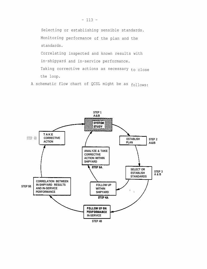
Selecting
Monitoring
standards.
Correlating
in-shipyard
- 113 -
or establishing sensible standards.
performance of the plan and the
inspected and known results with
and in-service performance.
Taking corrective actions as necessary
the loop.
A schematic flow chart of QCSL might be as
to close
follows:
STEP 1A&B
T A K ESTEP 6B CORRECTIVE ESTABLISH
ACTIONSTEP 2
PLAN A&B
ANALYZE & TAKECORRECTIVEACTION WITHINSHIPYARD
SELECT ORESTABLISHSTANDARDS
CORRELATION BETWEEN
STEP 5B IN-SHIPYARD RESULTS FOLLOW UPAND IN-SERVICE WITHINPERFORMANCE SHIPYARD
IN-SERVICE
STEP 4B
STEP 3A & B
- 114 -
QCSL can be divided into LOOP A and B - the former for
the shipyard, the latter for the shipyard and the in-service
performance results of the ship. Loop A yields short-range
benefits, while Loop B gives long-range gains. QCSL is
suitable for resolving single as well as multiple problems in
an effective way.
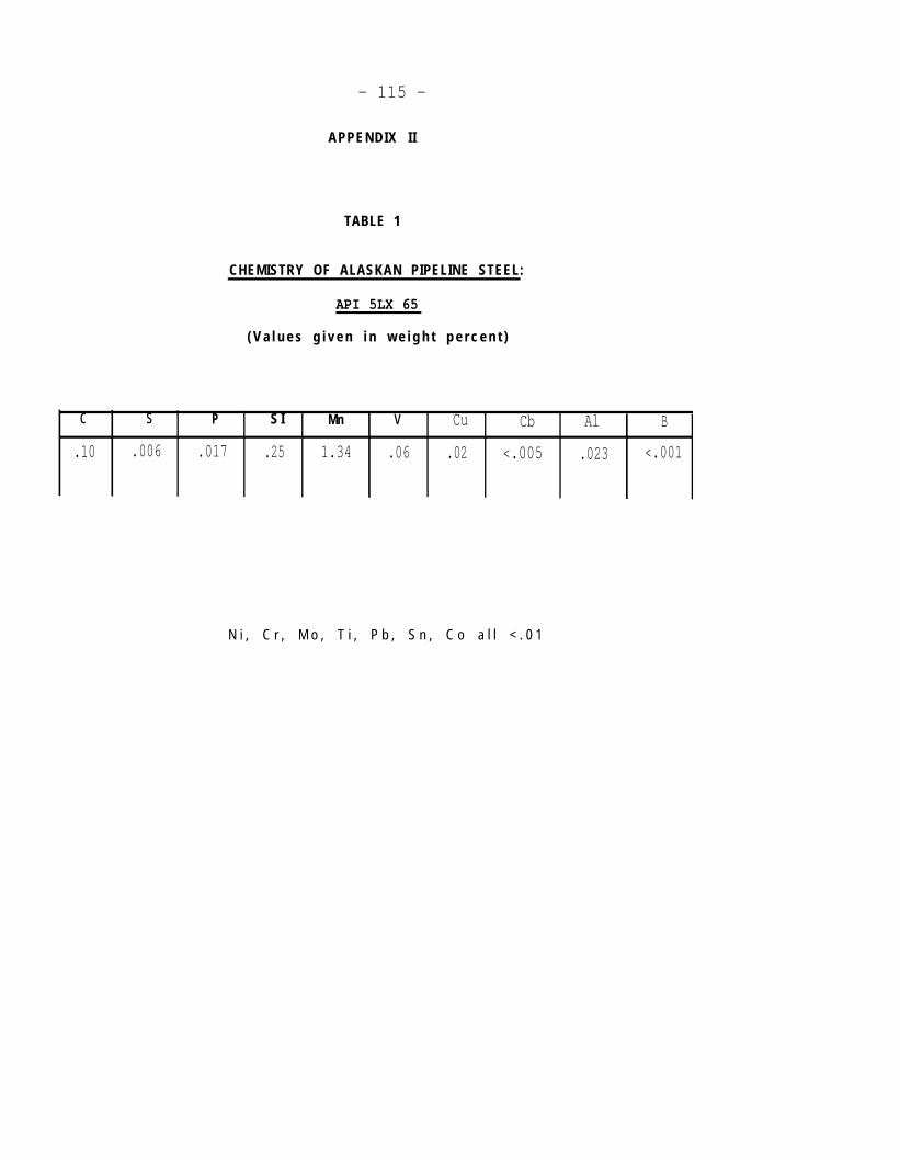
- 115 -
APPENDIX I I
TABLE 1
CHEMISTRY OF ALASKAN PIPELINE STEEL:
API 5LX 65
( V a l u e s g i v e n i n w e i g h t p e r c e n t )
c s P S I Mn v Cu Cb Al B
.10 .006 .017 .25 1.34 .06 .02 <.005 .023 <.001
N i , C r , M o , T i , P b , S n , C o a l l < . 0 1
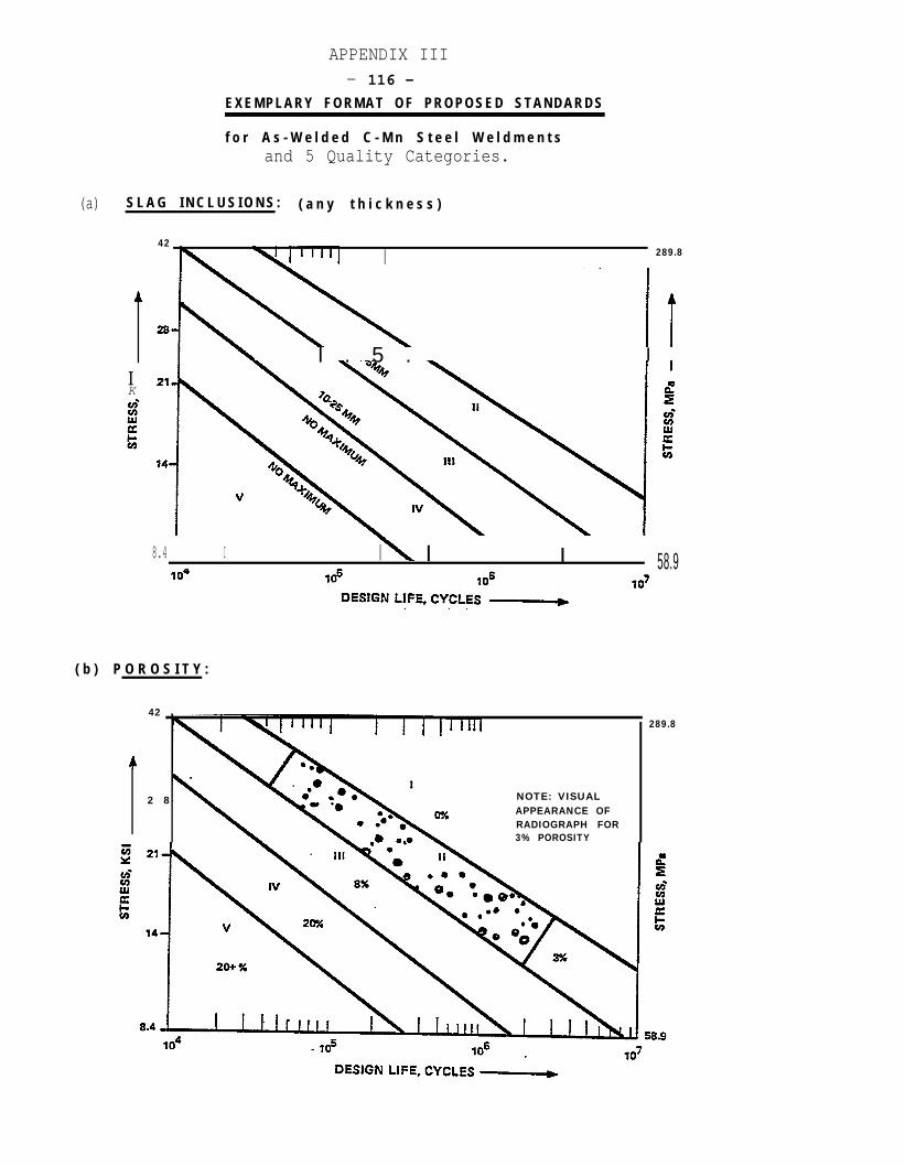
(a)
APPENDIX III- 116 -
E X E M P L A R Y F O R M A T O F P R O P O S E D S T A N D A R D S
f o r A s - W e l d e d C - M n S t e e l W e l d m e n t sand 5 Quality Categories.
S L A G I N C L U S I O N S : ( a n y t h i c k n e s s )
42
I 289.8
l . 5 . IIK
8.4 I I I I 58.9
( b ) P O R O S I T Y :
42289.8
2 8 NOTE: VISUALAPPEARANCE OFRADIOGRAPH FOR3% POROSITY
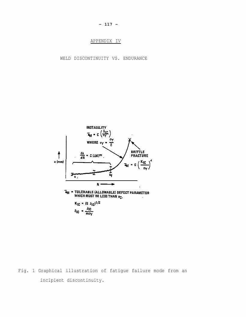
- 117 -
APPENDIX IV
WELD DISCONTINUITY VS. ENDURANCE
Fig. 1 Graphical illustration of fatigue failure mode from an
incipient discontinuity.