Embed Size (px)
Citation preview

Phil. Trans. R. Soc. A (2012) 370, 4115–4129doi:10.1098/rsta.2011.0260
The National Ignition Facility: the pathto a carbon-free energy future
BY CHRISTOPHER J. STOLZ*
Lawrence Livermore National Laboratory, 7000 East Avenue, Livermore,CA 94550, USA
The National Ignition Facility (NIF), the world’s largest and most energetic laser system,is now operational at Lawrence Livermore National Laboratory. The NIF will enableexploration of scientific problems in national strategic security, basic science and fusionenergy. One of the early NIF goals centres on achieving laboratory-scale thermonuclearignition and energy gain, demonstrating the feasibility of laser fusion as a viable source ofclean, carbon-free energy. This talk will discuss the precision technology and engineeringchallenges of building the NIF and those we must overcome to make fusion energy acommercial reality.
Keywords: laser fusion; precision optics; micro-machining; National Ignition Facility;laser inertial fusion energy
1. Introduction
The National Ignition Facility (NIF), shown in figure 1, is a 70 000 m2 facilityhousing a 192-beam precision optical instrument designed to deliver 1.8 MJ of3u (351 nm) temporally and spatially formatted laser energy [1,2]. The laserbeams propagate 1.5 km and are aligned and pointed to 50 mm root mean square(RMS), timed to arrive at the target within 10 ps, and power balanced within2 per cent. Through off-axis aspheric wedged focus lenses, the 3u lasers arefocused into a millimetre-sized volume called a hohlraum. The 192 lasers strike thehohlraum interior creating X-rays that bathe a millimetre-sized fusion capsule.The target is cryogenically cooled to 18◦K and held at a constant temperaturewithin ±0.001◦K. During the laser pulse, X-rays ablate the target and compressthe target to one-fortieth of its original radius. Under these conditions, targetswill achieve temperatures of 100 million degrees and pressures over 100 billionatmospheres. Within the target, hydrogen isotopes (tritium and deuterium) willfuse to form helium, neutrons and X-rays. Because of the mass change perEinstein’s famous equation E = mc2, there is a net production of energy.
Within 3 days of Theodore Maiman’s demonstration of the laser at HughesResearch Laboratory, Malibu, CA, John Nuckels at the Lawrence LivermoreNational Laboratory (LLNL) predicted that the laser could be used to generatethe necessary conditions to achieve fusion ignition and the concept of inertial*[email protected]
One contribution of 16 to a Discussion Meeting Issue ‘Ultra-precision engineering: from physics tomanufacturing’.
This journal is © 2012 The Royal Society4115
on July 16, 2018http://rsta.royalsocietypublishing.org/Downloaded from

4116 C. J. Stolz
Figure 1. Computer-aided drafting representation of the National Ignition Facility, a 70 000 m2 laserfacility constructed to demonstrate laser inertial confinement fusion. (Online version in colour.)
confinement fusion (ICF) was born [3]. In 1972, the ICF programme was started atLLNL with construction of a series of fusion lasers of increasing power culminatingin the completion of the NIF in 2008. Fusion lasers are actively being built andoperated internationally in multiple laser programmes including Omega EP atthe Laboratory for Laser Energetics (USA), Laser Megajoule (France), SG-IIIand SG-IV (China), HELEN and Orion (UK) and LFEX and GEKKO (Japan).
One of the central goals of the NIF is to provide the scientific validation of theICF process, creating a technical pathway for economically viable clean, carbon-free energy production [4]. The NIF laser was based on 1980s laser architecturethat could be scaled to a 40 × 40 cm aperture. A total of 500 TW of electricity isused to generate the pump light for the laser glass slabs. The use of flashlampson the NIF laser limits the electrical to laser energy efficiency to less than 1 percent. Additionally, the heat that is generated and the current cooling technologylimits the shot rate on the NIF laser to only a few shots daily.
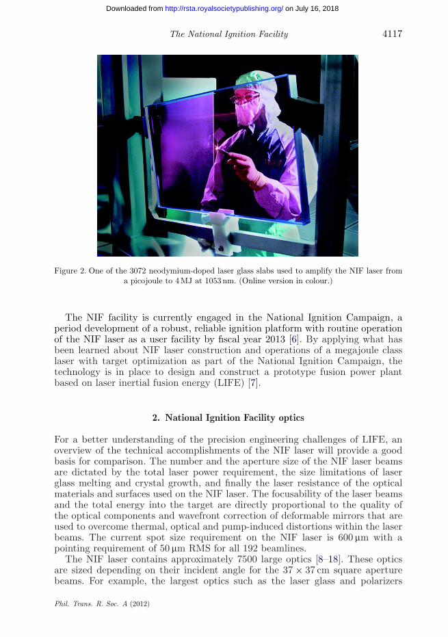
Today, the technologies exist to construct lasers with an electrical to laserenergy efficiency that is closer to 20 per cent using a laser diode and phosphate-based neodymium-doped laser glass architecture [5] (figure 2). Higher efficiencyis achieved by the narrow spectral emission of the pump source that is spectrallycentred within absorption bands of the laser glass. The reduced losses aremanifested as lower heat losses, which, combined with high-velocity heliumcooling, enables multi-hertz laser shot operations.
Phil. Trans. R. Soc. A (2012)
on July 16, 2018http://rsta.royalsocietypublishing.org/Downloaded from
The National Ignition Facility 4117
Figure 2. One of the 3072 neodymium-doped laser glass slabs used to amplify the NIF laser froma picojoule to 4 MJ at 1053 nm. (Online version in colour.)
The NIF facility is currently engaged in the National Ignition Campaign, aperiod development of a robust, reliable ignition platform with routine operationof the NIF laser as a user facility by fiscal year 2013 [6]. By applying what hasbeen learned about NIF laser construction and operations of a megajoule classlaser with target optimization as part of the National Ignition Campaign, thetechnology is in place to design and construct a prototype fusion power plantbased on laser inertial fusion energy (LIFE) [7].
2. National Ignition Facility optics
For a better understanding of the precision engineering challenges of LIFE, anoverview of the technical accomplishments of the NIF laser will provide a goodbasis for comparison. The number and the aperture size of the NIF laser beamsare dictated by the total laser power requirement, the size limitations of laserglass melting and crystal growth, and finally the laser resistance of the opticalmaterials and surfaces used on the NIF laser. The focusability of the laser beamsand the total energy into the target are directly proportional to the quality ofthe optical components and wavefront correction of deformable mirrors that areused to overcome thermal, optical and pump-induced distortions within the laserbeams. The current spot size requirement on the NIF laser is 600 mm with apointing requirement of 50 mm RMS for all 192 beamlines.
The NIF laser contains approximately 7500 large optics [8–18]. These opticsare sized depending on their incident angle for the 37 × 37 cm square aperturebeams. For example, the largest optics such as the laser glass and polarizers
Phil. Trans. R. Soc. A (2012)
on July 16, 2018http://rsta.royalsocietypublishing.org/Downloaded from

4118 C. J. Stolz
at nearly a metre on diagonal are used at Brewster’s angle. In the preamplifiersection and diagnostic systems, there are an additional 30 000 small (less than15 cm diameter) optics on the NIF laser.
(a) Optics manufacturing
The manufacturing rate needed for the NIF large optics was an orderof magnitude faster than what was achieved for the 10-beam 100 kJ classNOVA laser, the NIF predecessor constructed at LLNL in the early 1980s.Additionally, the 3u (351 nm) fluences for NIF optics are an order of magnitudegreater than for NOVA optics. To achieve these manufacturing rates, a3 year development programme, started in 1994, was aimed at demonstratingdeterministic manufacturing methods that could be scaled to metre-class opticsduring a 3 year facilitation phase. A 1 year pilot production phase commencedto optimize the full-scale manufacturing processes on the new equipment in 2000followed by an 8 year production phase culminating in optics completion at theend of 2008.
Throughout the optics manufacturing process, the material removal ratedecreases from grinding through polishing. The key to reducing the opticalfabrication manufacturing time is in quickly converging to the final desiredflatness or shape at each manufacturing step, thus minimizing the amountof material removal needed during the slower subsequent fabrication steps.Traditionally, optics were manufactured using fairly labour-intensive processes,such as loose–abrasive grinding and highly skilled opticians with few controlsover continuous polisher flatness. This necessitated a high number of iterationsbetween interferometry and polishing before finally meeting specification. Theseprocesses have been replaced by deterministic processes such as fixed abrasivegrinding, high-speed synthetic lap polish out, and computer controls oncontinuous polishers to maintain lap flatness for improved predictability of whenan optic meets specifications. As an example of the improved convergence,the number of wavefront testing iterations for amplifier slabs dropped byan order of magnitude when manufacturing the NIF laser slabs. Double-sided polishing has also been used on the NIF laser windows to reduce theirmanufacturing time.
Small-tool figuring processes such as magnetorheological finishing (MRF;illustrated in figure 3), computer-controlled optical surfacing and ion figuringare all highly deterministic figuring processes that have been employed forthe NIF laser to achieve the NIF laser wavefront specifications of 211 nm P-Vand 7 nm cm−1 RMS gradient. Early experience with these processes illustratedthat small periodic spatial frequencies polished into the optical surface, whichmay meet the P-V and RMS gradient specification, could still lead to phasemodulations and hence downstream amplitude beam modulations. Power spectraldensity specifications resolved this problem by controlling the amplitude of theperiodic wavefront phase [19]. Polishing tools had to be optimized to meet thesenew specifications.
(b) Precision fabrication for high-fluence operations
The combined surface area of the NIF large optics is 40 times larger than theKeck primary mirror, while NIF optics must survive a photon flux that is 19
Phil. Trans. R. Soc. A (2012)
on July 16, 2018http://rsta.royalsocietypublishing.org/Downloaded from

The National Ignition Facility 4119
Figure 3. Magnetorheological finishing machine capable of polishing metre-class optics to meet thestringent wavefront and laser resistance requirements. (Online version in colour.)
orders of magnitude greater than the Keck mirror. The highest stressed opticsin fusion lasers are those located in the 3u section of the laser. Improved laserresistance has remained an active area of research since the beginning of the laserfusion programme and will continue to be an active area for future improved NIFlaser performance (potential 3u operations above 1.8 MJ) or reduced operationscosts of the NIF laser by increasing optic lifetime. Initiated laser damage istypically about 30 mm in diameter with a melt zone of about 1 mm caused byhighly absorbing precursors that are less than 100 nm in diameter. Today, NIFlarge optics are being consistently manufactured with less than 10−13 of the opticalsurface area covered with 3u absorbing defects that could initiate laser damage atthe peak NIF laser operating fluence. What might appear at first to be conflictingrequirements, the quality of the surfaces needed to improve to reduce the numberof nano-absorbing defects that initiate laser damage, while the manufacturingtime needed to be reduced to lower costs, but, in reality, better process controland increased determinism for faster fabrication reduces the surface flaws leadingto high laser-resistant optics.
For 3u laser fusion optics, a link between surface flaws such asscratches, fractures and digs and degraded laser resistance has been clearlyestablished [20–22]. To minimize these flaws, polishing research has focusedon the following: minimization of grinding-induced damage, determination ofadequate material removal between manufacturing steps to remove subsurfacedamage, shear polishing, elimination of rogue particles during polishing,post-surface treatment to eliminate absorption centres and mitigation strategiesto arrest damage growth. Through this research, the number of surface
Phil. Trans. R. Soc. A (2012)
on July 16, 2018http://rsta.royalsocietypublishing.org/Downloaded from

4120 C. J. Stolz
initiation sites on NIF 3u optics has dropped by four orders of magnitudesince 1997.
MRF has been demonstrated to significantly increase the 3u laser resistanceof fused silica surfaces by removing polishing-induced subsurface damage [23].Unlike conventional lap polishing, in which the mechanical forces of the polishingparticles are perpendicular to the workpiece, MRF polishing uses shear forcesleading to significantly less fracturing and cracking of the surface. The carbonyliron within the magnetic field also creates an effective filter that restrictsparticles larger than the polishing compound from reaching the workpiece. Thedisadvantage of MRF is that some of the iron becomes embedded in the hydratedsurface layer, known as the Beilby layer. Iron strongly absorbs at 3u, leading tomicro-pitting of the surface when laser irradiated. This micro-pitting leads toa haziness of the optical surface, known as grey haze. Chemically etching thesurface removes the 100 nm thick Beilby layer and embedded iron, leaving a 3ulaser-resistant surface with no micro-pitting.
Since MRF polishing does not create subsurface damage, it is an ideal tool todetermine the subsurface damage depth of the various manufacturing steps usedto shape, grind, polish and figure an optic [24]. Combined with acid etching, awedge polished into the surface with MRF makes it fairly easy to determine thetypical subsurface damage depth that occurred during the preceding fabricationstep. Through this work, it has been determined that the conventional wisdomof removing three times the particle diameter of the previous processing stepis typically inadequate. It has also been shown that the amount of materialthat needs to be removed on each processing step is extremely process andequipment dependent, mandating characterization before being able to come upwith processes that yield minimal subsurface damage.
The potassium dihydrogen phosphate (KDP) and deuterated potassiumdihydrogen phosphate (DKDP) frequency conversion crystals used on the NIFlaser are diamond turned owing to the high solubility and softness of the crystalmaking conventional polishing very difficult. Subsurface characterization was usedto determine the optimum material removal values for each cut to yield high-fluence surfaces. Initial MRF studies of KDP material demonstrate promisingresults for not only increasing the surface laser resistance, but also reducing thesurface roughness caused by the diamond turning lines [25].
(c) Optics processing
Although flaw and defect reductions have proved remarkably successful byreducing laser damage precursors by over two orders of magnitude, their completeremoval is unrealistic owing to the time and cost necessary to manufacturecompletely flaw-free optics. Therefore, three processing strategies have beendeveloped to make flaws that initiate within the NIF laser fluence operatingrange benign. These processes have been termed mitigation because not only areunstable laser-initiated growth sites arrested, but also any features that remain onthe optic have minimal forward propagating intensification so that downstreamoptics are not put at risk of laser damage.
For the NIF laser, a number of mitigation strategies have been developed forspecific purposes. One approach is to pre-irradiate the optic with a low fluenceand ramp to the operating fluence (or slightly above the operating fluence). This
Phil. Trans. R. Soc. A (2012)
on July 16, 2018http://rsta.royalsocietypublishing.org/Downloaded from

The National Ignition Facility 4121
process is also known as laser conditioning and has been applied to laser glass,KDP and DKDP crystals and optical coatings. A gentle fluence ramp tends toinitiate laser damage on a significantly smaller scale or possibly, in the case ofcrystals, creates a photo-induced absorption reduction of bulk defects, leavingmicrometre-sized initiated sites within the bulk or on the surface that are stableto the NIF laser operating fluence. As long as the bulk scatter is less than 0.1 percent, the crystal is usable on the NIF laser. In the case of crystals, it has beenfound that the optimum pulse length for laser conditioning is a pulse shorter than1 ns compared with the NIF laser operating pulse, which can exceed 20 ns with avery complex temporal pulse shape [26,27].
In the case of multi-layer high-reflector optical coatings, 1 mm sizeinclusions embedded within the film cause a geometrically induced electric-field intensification, which leads to the formation of a plasma during laserirradiation [28]. The nodular defect is ejected, leaving a micro-pit in the surface.By using a gentle fluence ramp, this ejection can leave non-fractured micro-pittingthat is laser resistant above the NIF 1u operating fluence of 20 J cm−2 at a 3 nspulse length.
Laser glass was also pre-treated with an off-line laser scanning system [29]. Solidmicrometre-sized inclusions of highly absorbing platinum are damaged duringthis pre-treatment process. The laser glass slabs have been sorted and binned byplatinum damage sizes. Slabs with no platinum are placed into the highest fluencesections of the laser. Slabs with larger platinum size damage are placed into thelowest fluence sections of the laser.
An alternative mitigation approach has been to chemically treat fused silicaoptics to reduce the atomic flaws within surface fractures and cracks. Thesefractures are residual subsurface damage from grinding, polishing or opticshandling that are exposed once the Beilby layer is etched away. Fracturescaused before the polishing process is completed can lead to absorbing polishingcompound embedded into the surface. Suratwala and his team have determineda hydrofluoric acid-based buffered oxide etch process that removes the absorbingsites within fused silica optics without introducing absorbing etchant by-productsthrough the use of proper etchant chemistry, agitation and rinsing [30]. Althoughthe scratches and fractures increase in size and cause increased scatter, theelimination of the absorbing defects within the fractures makes these surfaceflaws benign to the 3u laser, thus reducing surface initiation by two ordersof magnitude.
A third mitigation strategy that has been developed is the micro-machiningof initiated flaws to remove the absorbing damaged material. Through theuse of CO2 lasers, fused silica surfaces can be machined to remove absorbingmaterial while leaving a carefully sculpted pit that minimizes the laser amplitudemodulation at downstream optic locations (figure 4). Thermal flow can be usedto melt the absorbing material and, through surface passivation, a low absorbingpit can be created [31]. A second technique using evaporative machining can alsocreate benign conical pits yielding a high laser resistance [32].
The mitigation strategy used for KDP and DKDP crystal surfaces is a high-speed single-crystal diamond drill to also create non-absorbing conical pits [33].This mechanical approach to micro-machining overcomes thermal cracking issuescaused by laser machining, while creating very reproducible pit geometries thatminimize laser amplitude modulation at downstream optic locations [34].
Phil. Trans. R. Soc. A (2012)
on July 16, 2018http://rsta.royalsocietypublishing.org/Downloaded from

4122 C. J. Stolz
12.5 ms CO2laser pulse
scanninglaser spot
damage withsubsurface cracks
Figure 4. Fused silica laser damage material is removed by CO2 laser micro-machining leaving asmooth laser-resistant pit and laser-hardened optical surface. (Online version in colour.)
Micro-machining mitigation technologies are also being developed forhigh-reflector coatings. Optical interference coatings are composed of multiplematerials with different thermal expansion coefficients and absorption spectra,leading to significant thermal cracking when attempting the CO2 laser machiningprocesses used for fused silica. Electric-field intensification owing to large conicalpit angles created by the KDP crystal high-speed diamond drill leads to pitswith low laser resistance at the nanosecond pulse length used for the NIFlaser [35]. Femtosecond laser machining combines the advantages of a non-thermalablative process that can create pits with steep sidewalls for minimal electric-fieldintensification for laser-resistant mitigation pits [36]. A mitigation strategy thatwas developed for sol-gel coatings consisted of a syringe with decane to dissolvethe coating, leaving a circular uncoated region around an optic flaw with littledownstream modulation [37].
One final advantage of the micro-machining mitigation technologies is that,once all of the initiating flaws are exposed during normal NIF laser operationsor off-line laser conditioning scans, the growing sites can be removed leaving arobust laser-hardened optic ready for reinstallation.
(d) High-fluence laser operations
The ability to detect and track growing flaws on NIF optics has a significantpositive impact on NIF laser operations. Optics can be laser hardened througha process of flaw initiation, optical removal and mitigation for reinstallation ata future date. Within NIF, there are two inspection systems. The large opticinspection system is located in the multi-pass cavity within the 1u section of thelaser to capture all of the laser bay optics from the deformable mirror (LM1) tothe diagnostic beamsplitter after the final spatial filter lens. Final optics damageinspection (FODI), shown in figure 5, can be inserted at the centre of the targetchamber between shots to look up each individual beamline to characterize thefinal optics in the target bay and transport mirrors in the switchyard [38].
Phil. Trans. R. Soc. A (2012)
on July 16, 2018http://rsta.royalsocietypublishing.org/Downloaded from

The National Ignition Facility 4123
Figure 5. The final optics damage inspection system is used to track surface flaws on optics forNIF laser operations. (Online version in colour.)
FODI has to detect and locate 30 mm damage sites with 99 per cent confidenceand determine their size to within 15 per cent. A history of the growth of thedamage sites is created to help predict, based on the upcoming planned lasershots, the optic lifetime so that the optic can be removed before sites reach300 mm. FODI must also provide accurate x- and y-coordinate locations of eachflaw for future mitigation and repair. For the range of optics locations in NIF,FODI must operate over a working distance of 5–80 m. This is equivalent tofinding a contact lens floating in a 0.8 km diameter pond from an elevation of450 m. Finally, FODI must capture images of all of the most critical 960 opticsin 192 beams within only 2 hours while under vacuum at less than 10−4 torr.
To accomplish these stringent goals, a 16-megapixel high-resolution camera islocated on a six-axis gymbal mounted to a 9000 kg 5 m long extractable boom.Both dark- and bright-field images can be collected using an alignment laser.For higher resolution, incoherent side lighting has been installed surrounding themost critical optics. Additionally, fiducials have been added to the optics as areference for the x- and y-coordinate system used to map each of the flaws. Finally,radiometry is used to determine the flaw size when compared with known damagesites on test optics as well as the fiducials.
Programmable beam blockers have also been constructed and installed on theNIF laser [39]. These devices can create low-fluence smooth apodized shadows inthe NIF laser beam. When combined with the FODI data, these shadows can beco-aligned to growing damage sites on final optics. With low-fluence irradiation,these damage sites become stable, thus extending the operational lifetime of theoptic and enabling removal during scheduled preventative maintenance periodson the NIF laser.
Phil. Trans. R. Soc. A (2012)
on July 16, 2018http://rsta.royalsocietypublishing.org/Downloaded from

4124 C. J. Stolz
Figure 6. Computer-aided drafting representation of a future laser inertial fusion energy powerplant. (Online version in colour.)
3. Laser fusion power plant
The primary difference between the LIFE (figure 6) and NIF lasers is the shotrate (15 Hz versus 1 × 10⁻⁴ Hz) and the electrical to laser conversion efficiency(less than 1% versus approx. 20%). These requirements drive a new laserarchitecture based on laser diodes instead of flashlamps to pump the amplifierslabs. The disadvantage of flashlamp pumping is that much of the broadbandspectral emission does not pump the electrons to a higher state allowing foramplified emission, but instead creates phonons or heat. The more efficient diodepumping results in significantly less heat accumulation, enabling multi-hertz lasershot operations.
The 7680 NIF flashlamps are nearly 180 cm long cylindrical xenon lampsinstalled in close proximity to the laser glass slabs. Each flashlamp is driven by50 000 J of electricity. Metallic-shaped reflectors are located behind the flashlampsto reflect the broadband emitted light into the amplifier slabs. In contrast, diodepumping will require optical components to format and steer the diode light intothe amplifier assembly. To accomplish this, approximately 40 per cent of the totaloptic surface area and 50 per cent of the total optic volume in the LIFE facility isdedicated to pump optics compared with no large optics needed for NIF flashlamppump delivery.
Phil. Trans. R. Soc. A (2012)
on July 16, 2018http://rsta.royalsocietypublishing.org/Downloaded from

The National Ignition Facility 4125
A significant operational constraint for a power plant is high availability.High reliability and modular serviceability are fundamental attributes neededto achieve an availability of about 99 per cent expected for LIFE plants [7]. Themodularity concept has been a primary design philosophy used in most large laserfacilities. For example, the Atomic Vapour Laser Isotope Separation programmeat LLNL had redundant copper vapour lasers (CVLs) that were self-containedbeam boxes that ran continuously [40]. During maintenance cycles, a CVL couldbe removed and swapped with a functional unit. The ability to increase the powerof adjacent lasers enabled continuous operations at the desired power levels,even during this maintenance period. A similar strategy is envisioned for theLIFE plant.
The 1u amplifier is envisioned to be a self-contained beam box that wouldhouse the amplifiers, spatial filters, diode pumping, diagnostic and relay opticsthat would fit into a 30 m3 box capable of being transported in a standard tractortrailer truck. Compared with a NIF beamline in the laser bay, this LIFE box isan order of magnitude shorter in length. This is accomplished by an architecturethat multi-passes the optics, folds the beams and uses normal incident laserglass slabs and a smaller aperture for shorter spatial filters. Both the NIF andLIFE systems use a Pockels cell to multi-pass amplifier slabs and to reduce thesize of the building and to minimize the number of optical components. Bothsystems are based on a four-pass configuration, unlike the single-pass architectureused for the NOVA laser. Currently, the NIF laser bay has two adjacent spatialfilters that occupy approximately 70 per cent of the laser bay path length. TheLIFE beam boxes are folded one on top of the other, significantly reducingthe footprint. The NIF amplifier slabs are used in an open Brewster’s angle(56.5◦) alternating zigzag pattern to facilitate flashlamp pumping. The NIFconfiguration also eliminates the need for antireflection coatings on the slabs;however, it consumes a large path length compared with the normal incidenceLIFE amplifier assembly. Finally, a square aperture of 27 cm (LIFE) versus37 cm (NIF) significantly shortens the spatial filters and enables the use of lowerf-number lenses.
These beam boxes would be manufactured and assembled at commercialvendors and shipped to the LIFE plant ready for installation. Kinematicallymounted in the LIFE facility, beam boxes will be easy to swap to remove lasersin need of service and replace with new ones. Built-in auto-alignment systemswould minimize the amount of downtime and the expertise needed by plantoperations technicians.
A comparable strategy would be used for the transport mirrors. They wouldalso be housed in a modular box. One of the disadvantages with the NIF beamdelivery architecture is a wide range of mirror types, and angles are needed to steerthe beams into the target chamber. The use of a hohlraum dictates conversionof the linear array of beams in the laser bay into a cylindrical configuration withupper and lower cones of light converging to the centre of the target chamber.Because of the short beam box length, a carousel configuration, illustrated infigure 6, minimizes the number of different beam transport box configurationsand also significantly reduces the overall footprint of the LIFE building.
The number of beam boxes is dictated by the total power requirements forignition, laser power handling of the individual optical components and aperturesize. Because of the higher laser resistance at 1u than 3u, smaller apertures are
Phil. Trans. R. Soc. A (2012)
on July 16, 2018http://rsta.royalsocietypublishing.org/Downloaded from
4126 C. J. Stolz
used in the amplifier beam boxes than in the beam steering optics that are thesame aperture as NIF final optics.
The additional requirement of high availability for a commercial power plantalso factors into the number of beamlines and aperture needed for a LIFE plant.Therefore, improved laser resistance remains an active area of research for futureimproved NIF laser performance (potential operations above 1.8 MJ), reducedoperations costs on the NIF laser by increasing optic lifetime, and an opportunityto reduce the construction costs of future LIFE power plants through smalleroptic sizes.
A LIFE plant would require a comparable production time period tomanufacture almost 10× more optics than on the NIF laser. At nearly fivetimes greater surface area and two times more glass volume, optics precisionmanufacturing will need to transition from a custom optics manufacturing modelto true high-volume manufacturing.
4. Conclusions
Precision engineering has been a crucial part of the success of the fabricationof the NIF laser. Throughout the entire facility, extremely high precision isneeded to create the pulse-formatted beam, amplify it for uniform power balance,point it to the target and time the arrival of each of the beams to the target.Without this precision, targets would not compress symmetrically to achievethe conditions necessary for fusion. Precision engineering will play a crucial rolein the design, development and construction of future fusion power plants toreduce our dependence on fossil fuels and the potentially damaging impact onthe environment.
This work was performed under the auspices of the US Department of Energy by LawrenceLivermore National Laboratory under contract DE-AC52-07NA27344.
References
1 Haynam, C. A. 2007 National Ignition Facility laser performance. Appl. Opt. 46, 3276–3303.(doi:10.1364/AO.46.003276)
2 Miller, G. H., Moses, E. I. & Wuest, C. R. 2004 The National Ignition Facility. Opt. Eng. 43,2841–2853. (doi:10.1117/1.1814767)
3 Nuckolls, J., Wood, L., Thiessen, A. & Zimmerman, G. 1972 Laser compression of matter tosuper-high densities: thermonuclear (CTR) applications. Nature 239, 139–142. (doi:10.1038/239139a0)
4 Dunne, M. 2010 Fusion’s bright new dawn. See http://physicsworld.com/cws/article/print/42423.
5 Bayramian, A., Deri, B., Fulkerson, S., Lanning, R. & Telford, S. 2011 Compact, efficient, low-cost diode power conditioning for laser inertial fusion energy in high power lasers for fusionresearch. Proc. SPIE. 7916, 7960B.
6 Moses, E. I. 2009 Ignition on the National Ignition Facility: a path towards inertial fusionenergy. Nucl. Fusion 49, 104022. (doi:10.1088/0029-5515/49/10/104022)
7 Moses, E. I. et al. 2009 A sustainable nuclear fuel cycle based on laser inertial fusion energy.Fusion Sci. Technol. 56, 547–565.
8 Campbell, J. H. et al. 2004 NIF optical materials and fabrication technologies: an overview.In Optical engineering at the Lawrence Livermore National Laboratory II: the National Ignition
Phil. Trans. R. Soc. A (2012)
on July 16, 2018http://rsta.royalsocietypublishing.org/Downloaded from

The National Ignition Facility 4127
Facility, vol. 5341 (eds M. A. Lane & C. R. Wuest), pp. 84–101. Bellingham, WA: SPIE.(doi:10.1117/12.538471)
9 Campbell, J. H., Hayden, J. S. & Marker, A. 2011 High-power solid-state lasers: a laser glassperspective. Int. J. Appl. Glass Sci. 2, 3–29. (doi:10.1111/j.2041–1294.2011.00044.x)
10 Campbell, J. H. & Suratwala, T. I. 2000 Nd-doped phosphate glasses for high-energy/high-peak-power lasers. J. Non-Cryst. Solids 263/264, 318–341. (doi:10.1016/S0022-3093(99)00645-6)
11 Campbell, J. H. et al. 2000 Continuous melting of phosphate laser glasses. J. Non-Cryst. Solids263/264, 342–357. (doi:10.1016/S0022-3093(99)00675-4)
12 Ehrmann, P. R., Campbell, J. H., Suratwala, T. I., Hayden, J. S., Krashkevich, D. & Takeuchi,K. 2000 Optical loss and Nd3+ non-radiative relaxation by Cu, Fe and several rare earthimpurities in phosphate laser glasses. J. Non-Cryst. Solids 263/264, 251–262. (doi:10.1016/S0022-3093(99)00682-1)
13 Hayden, J. S., Marker III, A. J., Suratwala, T. I. & Campbell, J. H. 2000 Surface tensile layergeneration during thermal annealing of phosphate glass. J. Non-Cryst. Solids 263/264, 228–239.(doi:10.1016/S0022-3093(99)00672-9)
14 Suratwala, T. I., Steele, R. A., Wilke, G. D., Campbell, J. H. & Takeuchi, K. 2000 Effects ofOH content, water vapor pressure, and temperature on sub-critical crack growth in phosphateglass. J. Non-Cryst. Solids 263/264, 213–227. (doi:10.1016/S0022-3093(99)00680-8)
15 Suratwala, T. I., Miller, P. E., Ehrmann, P. R. & Steele, R. A. 2005 Polishing slurry inducedsurface haze on phosphate laser glasses. J. Non-Cryst. Solids 351, 2091–2101. (doi:10.1016/j.jnoncrysol.2005.04.046)
16 Hawley-Fedder, R. A. et al. 2004 NIF Pockels cell and frequency conversion crystals. InOptical engineering at the Lawrence Livermore National Laboratory II: the National IgnitionFacility, vol. 5341 (eds M. A. Lane & C. R. Wuest), pp. 121–126. Bellingham, WA: SPIE.(doi:10.1117/12.538482)
17 Wegner, P. et al. 2004 NIF final optics system: frequency conversion and beam conditioning.In Optical engineering at the Lawrence Livermore National Laboratory II: the National IgnitionFacility, vol. 5341 (eds M. A. Lane & C. R. Wuest), pp. 121–126. Bellingham, WA: SPIE.(doi:10.1117/12.538481)
18 Stolz, C. J., Adams, J., Shirk, M. D., Norton, M. A. & Weiland, T. L. 2005 Engineeringmeter-scale laser resistant coatings for the near IR. In Advances in optical thin films II,vol. 5963 (eds C. Amra, N. Kaiser & H. A. MacLeod), p. 59630Y. Bellingham, WA: SPIE.(doi:10.1117/12.625422)
19 Lawson, J. K., Wolfe, C. R., Manes, K. R., Trenholme, J. B., Aikens, D. M. & English Jr, R. E.1995 Specification of optical components using the power spectral density function. Proc. SPIE2536, 38–50. (doi:10.1117/12.218430)
20 Miller, P. E., Suratwala, T. I., Bude, J. D., Laurence, T. A., Shen, N., Steele, W. A., Feit, M. D.,Menapace, J. A. & Wong, L. L. 2009 Laser damage precursors in fused silica. In Laser-induceddamage in optical materials, vol. 7504 (eds G. J. Exarhos, V. E. Gruzdev, D. Ristau, M. J.Soileau & C. J. Stolz), p. 75040X. Bellingham, WA: SPIE. (doi:10.1117/12.836986)
21 Suratwala, T., Steele, R., Feit, M. D., Wong, L., Miller, P., Menapace, J. & Davis, P. 2008Effect of rogue particles on the sub-surface damage of fused silica during grinding/polishing.J. Non-Cryst. Solids 354, 2023–2037. (doi:10.1016/j.jnoncrysol.2007.11.015)
22 Suratwala, T., Wong, L., Miller, P., Feit, M. D., Menapace, J., Steele, R., Davis, P. & Walmer, D.2006 Sub-surface mechanical damage distributions during grinding of fused silica. J. Non-Cryst.Solids 352, 5601–5617. (doi:10.1016/j.jnoncrysol.2006.09.012)
23 Menapace, J. A. 2010 Developing magnetorheological finishing (MRF) technology for themanufacture of large-aperture optics in megajoule class laser systems. In Laser-induced damagein optical materials, vol. 7842 (eds G. J. Exarhos, V. E. Gruzdev, J. A. Menapace, D. Ristau &M. J. Soileau), p. 78421W. Bellingham, WA: SPIE. (doi:10.1117/12.855603)
24 Menapace, J. A., Davis, P. J., Steele, W. A., Wong, L. L., Suratwala, T. I. & Miller, P. E. 2005MRF applications measurement of process-dependent subsurface damage in optical materialsusing the MRF wedge technique. In Laser-induced damage in optical materials, vol. 5991 (edsG. J. Exarhos, K. L. Lewis, V. E. Gruzdev, A. H. Guenther, M. J. Soileau & C. J. Stolz),p. 599103. Bellingham, WA: SPIE. (doi:10.1117/12.638839)
Phil. Trans. R. Soc. A (2012)
on July 16, 2018http://rsta.royalsocietypublishing.org/Downloaded from

4128 C. J. Stolz
25 Menapace, J. A., Ehrmann, P. R. & Bickel, R. C. 2009 Magnetorheological finishing (MRF)of potassium dihydrogen phosphate (KDP) crystals: non-aqueous fluids development, opticalfinish, and laser damage performance at 1064 nm and 532 nm. In Laser-induced damage inoptical materials, vol. 7504 (eds G. J. Exarhos, V. E. Gruzdev, D. Ristau, M. J. Soileau & C.J. Stolz), p. 750414. Bellingham, WA: SPIE. (doi:10.1117/12.836913)
26 Adams, J. J. et al. 2006 Results of sub-nanosecond laser-conditioning of KD2PO4 crystals. InLaser-induced damage in optical materials, vol. 6403 (eds G. J. Exarhos, A. H. Guenther, K. L.Lewis, D. Ristau, M. J. Soileau & C. J. Stolz), p. 64031M. Bellingham, WA: SPIE. (doi:10.1117/12.696086)
27 Jarboe, J. A., Adams, J. J. & Hackel, R. P. 2007 Analysis of output surface damage resultingfrom single 351 nm, 3 ns pulses on sub-nanosecond laser conditioned KD2PO4 crystals. InLaser-induced damage in optical materials, vol. 6720 (eds C. J. Stolz, G. J. Exarhos, A.H. Guenther, K. L. Lewis, D. Ristau & M. J. Soileau), p. 67200J. Bellingham, WA: SPIE.(doi:10.1117/12.752957)
28 Stolz, C. J., Feit M. D. & Pistor T. V. 2006 Laser intensification by spherical inclusionsembedded within multilayer coatings. Appl. Opt. 45, 1594–1601. (doi:10.1364/AO.45.001594)
29 Weinzapfel, C. L. et al. 1988 Large scale damage testing in a production environment. InLaser-induced damage in optical materials, vol. 756 (eds H. E. Bennett, A. H. Guenther, B.E. Newnam & M. J. Soileau), pp. 112–122. Boulder, CO: National Institute of Standards andTechnology.
30 Wong, L., Suratwala, T., Feit, M. D., Miller, P. E. & Steele, R. 2009 The effect of HF/NH4Fetching on the morphology of surface fractures on fused silica. J. Non-Cryst. Solids 355, 797–810.(doi:10.1016/j.jnoncrysol.2009.01.037)
31 Bass, I. L., Guss, G. M., Nostrand, M. J. & Wegner, P. J. 2010 An improved method ofmitigating laser-induced surface damage growth in fused silica using a rastered pulsed CO2laser. In Laser-induced damage in optical materials, vol. 7842 (eds G. J. Exarhos, V. E.Gruzdev, J. A. Menapace, D. Ristau & M. J. Soileau), p. 784220. Bellingham, WA: SPIE.(doi:10.1117/12.867862)
32 Adams, J. J., Bolourchi, M., Bude, J .D., Guss, G. M., Matthews, M. J. & Nostrand, M. C. 2010Results of applying a non-evaporative mitigation technique to laser-initiated surface damageon fused silica. In Laser-induced damage in optical materials, vol. 7842 (eds G. J. Exarhos, V.E. Gruzdev, J. A. Menapace, D. Ristau & M. J. Soileau), p. 784223. Bellingham, WA: SPIE.(doi:10.1117/12.867652)
33 Geraghty, P., Carr, W., Draggoo, V., Hackel, R., Mailhiot, C. & Norton, M. 2006 Surfacedamage growth mitigation on KDP/DKDP optics using single-crystal diamond micro-machining ball end mill contouring. In Laser-induced damage in optical materials, vol. 6403(eds G. J. Exarhos, A. H. Guenther, K. L. Lewis, D. Ristau, M. J. Soileau & C. J. Stolz), p.64030Q. Bellingham, WA: SPIE. (doi:10.1117/12.696076)
34 Ravizza, F. L., Nostrand, M. C., Kegelmeyer, L. M., Hawley, R. A. & Johnson, M. A. 2009Process for rapid detection of fratricidal defects on optics using line scan phase-differentialimaging. In Laser-induced damage in optical materials, vol. 7504 (eds G. J. Exarhos, V. E.Gruzdev, D. Ristau, M. J. Soileau & C. J. Stolz), p. 75041B. Bellingham, WA: SPIE.(doi:10.1117/12.836990)
35 Qiu, S. R., Wolfe, J. E., Monterrosa, A. M., Feit, M. D., Pistor, T. V. & Stolz, C. J. 2011Searching for optimal mitigation geometries for laser-resistant multilayer high-reflector coatings.Appl. Opt. 50, C373–C381. (doi:10.1364/AO.50.00C373)
36 Wolfe, J. E., Qiu, S. R. & Stolz, C. J. 2011 Fabrication of mitigation pits for improving laserdamage resistance in dielectric mirrors by femtosecond laser machining. Appl. Opt. 50, C1–C6.(doi:10.1364/AO.50.0000C1)
37 Monticelli, M. V., Nostrand, M. C., Mehta, N., Kegelmeyer, L., Johnson, M. A., Fair, J. &Widmayer, C. 2008 The HMDS coating flaw removal tool. In Laser-induced damage in opticalmaterials, vol. 7132 (eds M. J. Soileau, C. J. Stolz, G. J. Exarhos & D. Ristau), p. 71320V.Bellingham, WA: SPIE. (doi:10.1117/12.804458)
Phil. Trans. R. Soc. A (2012)
on July 16, 2018http://rsta.royalsocietypublishing.org/Downloaded from

The National Ignition Facility 4129
38 Condor, A. et al. 2007 Final optics damage inspection (FODI) for the National IgnitionFacility. In Laser-induced damage in optical materials, vol. 6720 (eds C. J. Stolz, G. J. Exarhos,A. H. Guenther, K. L. Lewis, D. Ristau & M. J. Soileau), p. 672010. Bellingham, WA: SPIE.(doi:10.1117/12.759131)
39 Heebner, J. 2010 A programmable beam shaping system for tailoring the profile of high fluencelaser beams. In Laser-induced damage in optical materials, vol. 7842 (eds G. J. Exarhos, V. E.Gruzdev, J. A. Menapace, D. Ristau & M. J. Soileau), p. 78421C. Bellingham, WA: SPIE.(doi:10.1117/12.867728)
40 Paisner, J. A. 1988 Atomic vapor laser isotope separation. Appl. Phys. B. 46, 253–260.(doi:10.1007/BF00692883)
Phil. Trans. R. Soc. A (2012)
on July 16, 2018http://rsta.royalsocietypublishing.org/Downloaded from