Embed Size (px)
Citation preview

Copyright 2003 Bay Area Retrofit Inc.
The Mudsill Connection in Retrofit Shearwalls
Introduction
Seismic Behavior of Level and Stepped Cripple Walls, a publication of the Consortium of Universities in Earthquake Engineering (CUREE), contains the following statement regarding damage from the Northridge Earthquake: “More than half of the $40 billion dollar property losses were due to failures of wood frame construction, primarily as a result of the damage or collapse of residential, single-family homes, multi-family apartments or condominiums.”(10) The San Francisco Bay Area is riddled with earthquake faults, some of which can rupture with an intensity far greater than that experienced at Northridge. The Association of Bay Area Governments (ABAG) expects that over 150,000 housing units in the Bay Area will be lost when just one of these, the Hayward Fault, ruptures with an expected magnitude of 7.2 or greater. Homeowners are not unaware of this fact. In response to homeowner demands to protect their homes from earthquake damage, many contracting firms in the Bay Area now specialize in residential wood frame seismic retrofit work. Through the transfer-tax retrofit rebate program the city of Berkeley actually pays 0.5% of the purchase price to every new homeowner if the money is spent on seismic retrofit work. Given that the average home in Berkeley costs close to $600,000, this can be a large amount of money. As a result of this policy, according to ABAG, Berkeley can be proud to say that over 80% of the homes in its jurisdiction have been retrofitted. Unfortunately, also according to ABAG, the majority of those retrofits will not perform as needed. While a very large number of homes are being retrofitted or have already been retrofitted in the Bay Area, the policy of all Bay Area Building departments, including Berkeley’s (which alone through its transfer tax retrofit rebate program has spent millions of dollar on residential retrofit projects) is what is known as the “do no harm” policy. This is based on their interpretations of section 3403.2 of the 1997 UBC, which simply states that the building departments shall approve any work that increase the “lateral-force-resisting strength or stiffness of an existing structure” as long as such work does not obviously damage the building. This policy holds true not only in the Bay Area, but in Southern California as well. There was a good reason for inserting section 3403.2 into the code; it encourages people to retrofit without having to meet the earthquake provisions required for new construction. However, in terms of the quality of work and complete lack of building department supervision, the work being done under the “do no harm” policy often translates into a “do no good” policy, resulting in the waste of millions of homeowner dollars.
Retrofit Shear Walls
Retrofit shear walls are an extremely important part of any retrofit. Probably the trickiest part of building a retrofit shear wall is attaching it to the existing mudsill. Therefore, it is important to address the different ways in which shear walls can be attached to a mudsill. This report will discuss four methods that are used to attach the lower edge of a shear wall to an existing mudsill. Diagram 1 on the next page shows what a cripple wall looks like from underneath the house where retrofit shear walls are commonly built.
1

Copyright 2003 Bay Area Retrofit Inc.
1 – the foundation 2 – the mudsill 3 – the 2x4 cripple wall stud 4 - the top plate 5 – the floor joist 6 – the floor you walk on
The Nailed Blocking Method The first method being discussed is the Nailed Blocking Method shown here. This method installs 2 x 4 blocks between the studs by nailing the blocks to the sill. See Diagram 2 below.
Diagram 1 Components of a cripple wall
The plywood is then nailed into the 2 x 4 blocks at the bottom of the panel with 8d commons (0.131 by 2 1/2”) using 4” o.c. edge nailing as specified in the 2003 ICBO publication (GSREB) and shown in Diagram 3 on the following page.
This particular method is recommended by the 2003 GSREB, Appendix Chapter 6 of the Uniform Code of Building Conservation (UCBC), Chapter 92 of the City of Los Angeles Building Code, the City of San Leandro Prescriptive Retrofit Plan-set, and by various other jurisdictions that have modeled their own guidelines on the Nailed Blocking Method. Each of these standards specifies that each block be attached to the existing mudsill with four 10d commons (0.148 by 3”).
Diagram 3 Plywood nailed to the
blocks
Diagram 2 The Nailed Blocking Method
2

Copyright 2003 Bay Area Retrofit Inc.
Contractors and engineers have recently shown some reservations about this method because the blocks tend to split. Most cripple walls in older Bay Area homes are built with full 2-inch thick studs placed 16” o.c. The blocks installed between the studs are therefore only 14 inches long or less. Short blocks tend to split. There is a block-splitting potential when the blocks are nailed vertically to the sill through the face of the 3-1/2 dimension of the 2 x 4, as well as when the plywood is nailed horizontally to the 1-1/2 inch dimension side of these blocks. This method is the only one used by contractors and engineers throughout the Bay Area.
As per the GSREB (Guidelines for the Seismic Retrofit of Existing Buildings) the blocks are installed onto the mudsill with four 10d commons (0.148 by 3”) and then the plywood is edge-nailed 4” o.c. with 8d commons (0.131 by 2 1/2”). One reason splitting can occur is that the installer places some of the 10d commons too close to the ends of the blocks. In regard to this problem, code consultant Jim Russell, P.E., says:
“The 1991, 1997 and 2001 NDS state that ‘Edge distances, end distances and spacing of nails shall be sufficient to prevent splitting of the wood.’ Therefore, no specific measurements apply. The 1997 UBC amended the 1991 NDS with a different statement for nail placement for wood-to-wood joints. The 1997 UBC says: ‘For wood-to-wood joints, the spacing center-to-center of nails in the direction of stress shall not be less than the required penetration (which is 12 diameters per 1991 NDS). Edge or end distances in the direction of stress shall not be less than one-half of the required penetration. All spacing and edge and end distances shall be such as to avoid splitting of the wood.’ ”
Applying the "one-half of the required penetration" from the second sentence regarding edge and end distance, to an 8d common nail, you get 0.5 x 0.131 x 12 = 0.786 inches, or just a tad over 3/4 inch. For a 10d common it would be 0.5 x 0.148 x 12 = 0.888 inches, or just a bit more than 7/8 inches. Therefore, a 1 inch distance from either an 8d or a 10d common nail to the end of a block complies with this limit. . . IF it does not split the wood when installed.”
3

Copyright 2003 Bay Area Retrofit Inc.
Wood frame expert Kelly Cobeen S.E. states:
“The codes stick to a performance criteria for nail spacing - if you can drive the nail without splitting the wood it is OK. If the wood splits you have to replace it. If I were nailing the blocks I would stagger the 10d nails a bit and move them back from the edge. I think as close as 1-1/2 inches to the edge is perceived to be OK - I like to see a bit more where possible. For the sill nailing, NDS Table 11N provides a value of 118 # for a 10d common (full length) with a 1-1/2" side member. This can be multiplied by a duration of load factor of 1.33. This gives 628 # per block or 470 plf.”
If the blocks split when nailed to the sill, it is quite tempting for the installer to leave those split blocks in place because of the time and labor involved in removing them. Furthermore, once the plywood is installed there is no way to tell if the nails attaching the plywood to the blocks have split the blocks. This can be further complicated if 8d common edge nails are not staggered or if they are spaced closer together than the GSREB specified 4” o.c. Installers often believe “the more and bigger the nails, the stronger the shear wall” and they purposely over-nail the shear walls; thus splitting the blocks. Splitting is also exacerbated when the installer uses nails that are thicker than the GSREB specified 0.131-inch diameter 8d common plywood nails. The chance of a contractor even following the GSREB is small because very few of them even know what it is. Furthermore, contractors often use dry and brittle utility grade 2 x 4’s that are prone to splitting. Even if the 2 x 4’s are of very high quality, sometimes in retrofit work blocks are needed that are less than 6 inches in length. These short blocks split quite easily unless pre-drilled both when attached to the mudsill and when the plywood is nailed to them. See Illustration 1. 2 x 4 Block on Mudsill
Illustration 1
Photograph courtesy of the CUREE-Caltech wood frame project, found on page 36 in publication No. W-17, Seismic Behavior of Level and Stepped Cripple Walls.
4

Copyright 2003 Bay Area Retrofit Inc.
Illustration 1 comes from the CUREE-Caltech wood frame project and is an example of how blocks were installed in order to build shears walls for their experiments. Even though this block has not split, outside the lab and under actual field conditions blocks these sizes are extremely susceptible to splitting. Based on this writer’s experience of shooting an estimated 50,000 nails into 2 x 4 framing with pneumatic nail guns, the blocks shown here appear to have been pre-drilled at nail locations and installed with a hammer. This seems apparent because the nails are not recessed into the wood, as would be the case if a pneumatic nail gun had been used. In actual retrofit work nails in the blocking are installed with pneumatic nail guns and the holes ARE NOT pre-drilled by any contractor who must compete with other contractors and make a living.
The 2003 GSREB is also very concerned with splitting of framing members:
“C304.4.1.1 Sheathing Installation Requirements – The provisions of this chapter limit the types of bracing materials permitted for use as cripple wall bracing to wood structural panel sheathing.15/32 inch thick (5 ply) plywood was chosen as the required sheathing over 3/8" thick (3 ply) plywood because of the large number of ruptured 3/8" thick plywood panels found and photographed in the MMI VIII and IX intensity areas caused by the Northridge Earthquake. The most important component of plywood sheathing is adequate nailing. The provisions of this chapter for nailing are specific as to size and spacing. The use of common nails, the nail size (8 penny) and edge spacing (4") are explicit and should not be exceeded or reduced. There are three reasons for this very specific requirement. To prevent splitting of existing wood framing 8d nails are considered optimum for 2x material. If splitting of studs is observed, pre-drilling of holes is recommended. (Pre-drilled holes should have a diameter of about 3/4 the diameter of the nail.)”
Staples also have a very high shear capacity. Table 2 on page 7 in NER-272 (1997 edition) rates the shear capacity of staples:
TABLE 2
STAPLE DIMENSIONS AND NORMAL, LATERAL DESIGN LOADS1.2
STAPLE 3 LATERAL LOAD Gage Diameter, In Inches Minimum Penetration, In Inches Load' (IM)
14 0.080 1 75
15 0.072 1 64
16 0.0625 1 52
Design values are based on a 10-year "normal load” duration. Table values shall be multiplied by applicable adjustment factors such as for load duration, wet service, temperature, end grain, and toe-nailing.. Staples shall have a 7/16-inch minimum outside dimension crown width. The tabulated allowable lateral values are for staples installed in Douglas Fir, Larch or Southern Pine (Group II species). Similarly, Table I on Page 3 of the International Staple, Nail and Tool Association RESEARCH REPORT: RR 23633 titled Allowable Loads for Nails and Staples, which was adopted by the city of L.A., also allows 64 pounds of lateral resistance for a 0.072 inch 15 gage staple with one inch of penetration.
5

Copyright 2003 Bay Area Retrofit Inc.
Stapling blocks to the sill is recom-mended because splitting is less likely when staples are used. The photo at right is a 14 inch 2 x 4 block with 114 2-1/2 inch staples attached to a 2 x 6. Based on NER-272 values, it has a capacity of 9,703.68 pounds. Note no splitting of the blocks. Also see the staple length in front of the tape measure between the 5 inch and 7-1/2 inch marks. Engineering calculations for staples are on the next pages.
6

Copyright 2003 Bay Area Retrofit Inc.
7
Copyright 2003 Bay Area Retrofit Inc.
8

Copyright 2003 Bay Area Retrofit Inc.
9

Copyright 2003 Bay Area Retrofit Inc.
It is also a good idea to staple the plywood to the blocks. Stapled shear walls are discussed in APA Research Report 154:
Stapled Shear Walls
”Staples provide a method for developing high design shears while still using 2-inch nominal framing. The small diameter of the staple legs is not as apt to cause splitting of the framing, as are closely spaced large diameter nails. The use of staples as fasteners in shear walls is partic-ularly useful to avoid any tendency to split the framing lumber in rehabilitation work where the lumber may be dry and existing fasteners may already be placed at minimum allowable spacing. Shear walls tested in this group consisted of panel sheathing fastened to lumber framing members with pneumatically driven staples. Design shears for these walls were obtained from the recommended values in NER-272.”
APA Report #138 also supports this use of staples. Page 12 of that report states in its Test Results and Discussion section: “Prior to the construction of Diaphragm 7, tests were conducted to study the fastener type and spacing required to develop high loads. Specimens consisted of an 8" x 16" piece of plywood fastened to framing identical to the top flange of the I-joists. During these tests it was discovered that a large number of either l0d or 16d nails, spaced less than 3" o.c. as required to develop high shears, often caused the framing member to split. On the other hand, the use of pneumatically driven staples showed that staples with a 7/16" crown could be driven as close as 1" o.c. without causing splitting, either at the time of driving or when the specimen was loaded in shear.”
1/2"x2-1/2" 15ga staples1" min. penetration intomudsill
Diagram 4 Stapled Blocking Method
“Diaphragm 7 test results indicated that staples are practical for high-load diaphragms. This diaphragm reached an ultimate load of 3925 pit for a load factor of 2.92.”
Tom Skaggs, Ph.D., P.E. with the American Plywood Association, states:
“Diaphragm 7 was nailed with 14 ga staples. 14 ga staples have a larger diameter than 15 ga staples. Although the connection is slightly different, it would appear to me that 15 ga staples even as close as 1” o.c. may not split.”
The NER value in Table 2 for a 15 ga staple is 64 pounds. 64 x 1.33 would then give us a value of 85.1 pounds per staple. To achieve the same value as four 10d nails would require 6 staples with 501.6 pounds of capacity per block (85.1 time 6 = 501.6). This exceeds the nailed block values achieved in the GSREB. If staples are used, splitting of the blocks is not an issue regardless of the kind of wood blocking or staple spacing the contractor uses in the field. Therefore, in situations where blocks are required, it is recommended that they be stapled with 2-1/2 inch 15 ga 7/16 inch crown staples. One of these staple guns and the available staple sizes for this staple gun are shown in Illustration 2.
10

Copyright 2003 Bay Area Retrofit Inc.
Illustration 2 Senco Stapler and 2 1/2 staples The APA also tested stapled shear walls and printed the results in Table 3, APA Report #154. The table can be found below.
The arrow and shaded area designate the 15 ga staples ratings.
11

Copyright 2003 Bay Area Retrofit Inc.
NER-272 also addresses stapled shear walls.
Table 20 from NER-272, page 21
MINIMUM NOMINAL FASTENER LENGTH 7 (In Inches) ALLOWABLE WALL SHEAR VALUES Fastener Spacing at Panel Edges ' (In Inches)
NNOMINAL NAIL5 DIAMETER (In Inches) OR STAPLE 6 GAGE Panels Applied Directly to Framing Panels Applied Over 1/2" or 5/8"
Gypsum Sheathing 6 4 3 22-1/8 or 3 340 510 685 870 0.148 smooth12
2 or2-1/2 255 385 510 650 0.131 smooth or deformed
0.120 smooth
0.113 smooth or deformed 0.099 smooth or deformed
.092 smooth
14 gage
3, 2-1/2 2-1/4 or 2 245
365
490
620
15 gage
2-1/2, 2-1/4
210
310
415
530
16 gage 170 255 2, 1-3/4 or 1-1/2 335 430
a) The first number is the spacing at supported panel edges; the second is the spacing at intermediate framing members. (b) Refer to the latest edition of National Evaluation Service, Inc. Report NER-272 (4) for current code-recognized allowable shearloads for shear walls with wood structural panel sheathing fastened with staples. (c) The load factor is determined by dividing the average ultimate load by the target design shear.
According to Table 20, 15 gage staples can be used to build shear walls that resist 530 plf, far greater than the 365 plf detailed in the GSREB and other retrofit guidelines. Regarding the possible splitting caused by over-stapling of shear walls in excess of the 2” o.c. edge stapling required for 530 plf panels found in Table 20, I would like to remind the reader of what Mr. Tom Skaggs Ph.D. P.E. of the American Plywood Association said:
”Please see APA Research Report 138. Specifically, Test Results and Discussion for Diaphragm #7. After discussing 10d nails splitting framing at 3" o.c. the report says: ‘On the other hand, the use of pneumatically driven staples showed that staples with a 7/16" crown could be driven as close to 1" o.c w/o causing splitting, either at the time of driving or when the specimens were loaded in shear.’
Diaphragm 7 was nailed with 14 ga staples. 14 ga staples have a larger diameter than 15 ga staples. Although the connection is slightly different, it would appear to me that 15 ga staples even as close to 1" o.c. may not split.”
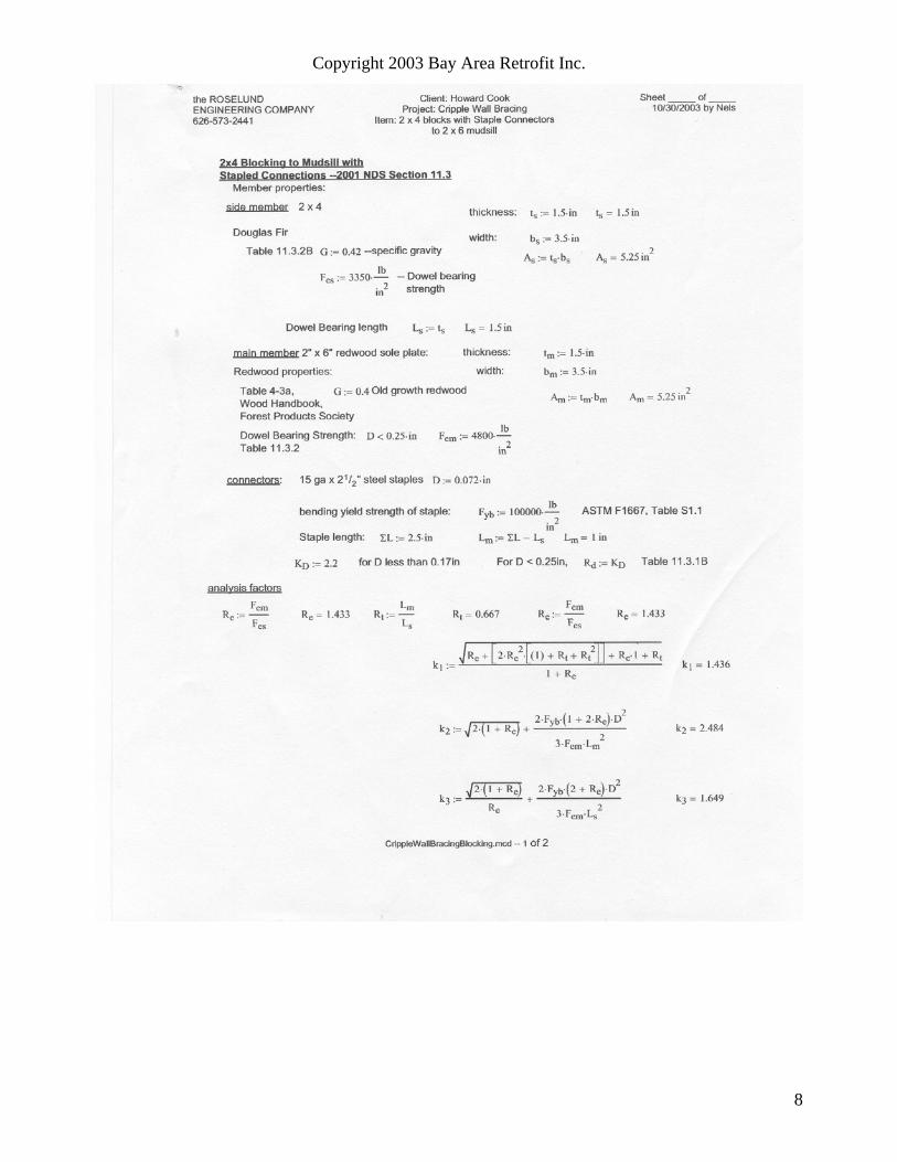
For calculated stapled shear wall values please see the following calculations by Nels Roselund, S.E.
12

Copyright 2003 Bay Area Retrofit Inc.
Z1D Lm⋅ Fem⋅
Rd:=Yield Limits Mode Im Equation 11.3-1 Z1 319lb=
Z2D Ls⋅ Fes⋅
Rd:= Mode Is Equation 11.3-2 Z2 51lb=
Z3k1 D⋅ Ls⋅ Fes⋅
Rd:= Equation 11.3-3 Mode II Z3 218lb=
Z4k2 D⋅ Lm⋅ Fem⋅
1 2 Re⋅+( ) Rd⋅:= Equation 11.3.4 Mode III.m Z4 188lb=
Z5k3 D⋅ Ls⋅ Fem⋅
2 Re+( ) Rd⋅:= Equation 11.3.5 Mode III.s Z5 57lb=
Z6D2
Rd
2 Fem⋅ Fyb⋅
3 1 Re+( )⋅⋅:= Controls Equation 11.3-6 Mode IV Z6 27lb=
Adjustment Factors
Geometry factor CΔ 1.0:= Section 11.5.1 Cm 1.0:= Moisture Content Table 10.3.3less than 19%
Diaphragm factor Cdi 1.1:= Section 11.5.3 Temperature < 100o Ct 1.0:= Table 10.3.4
Staple factor Cst 2:= two legs per staple Cg 1.0:= Group action factor Section 10.3.6
Duration factor Cd 1.33:=
Vallow Z6 CΔ⋅ Cm⋅ Cdi⋅ Ct⋅ Cst⋅ Cg⋅ Cd⋅:= Vallow 79lb=
Nailing Schedule
V6 Vallow2ft⋅:= V6 158
lbft
= 6"spacing, 2 staples per foot
V4 Vallow3ft⋅:= V4 237
lbft
= 4"spacing, 3 staples per foot
V3 Vallow4ft⋅:= V3 316
lbft
= 3"spacing, 4 staples per foot
V2 474lbft
=V2 Vallow6ft⋅:= 2"spacing, 6 staples per foot
V1.5 Vallow8ft⋅:= V1.5 633
lbft
= 1-1/2"spacing, 8 staples per foot
13

Copyright 2003 Bay Area Retrofit Inc.
The Reverse Block Method Another method of building retrofit shear walls is the Reverse Block Method shown in Diagram 5. This method can be used in homes that have wide mudsills.
The long 2 x 4 reverse block is nailed to the plywood and then the entire assembly is nailed to the cripple wall and mudsill as one piece. Wide mudsills are fairly common in older Bay Area homes.
The Flush-Cut Method
Diagram 5 The Reverse Block Method
The final alternate retrofit method is known as the Flush-Cut Method. In this method the mudsill is cut away so that the mudsill is now flush with the 2 x 4 framing. The lower edge of the plywood is then nailed directly into the mudsill. This method is illustrated in Diagrams 6 and 7. Using Table 23-II-I-1 and footnote 1 of the UBC we can build shear walls with a capacity of 713 plf using 10d commons.
Diagram 6 Mudsill is cut flush
with studs
Diagram 7 Plywood is nailed to the flush-cut mudsill
14
Copyright 2003 Bay Area Retrofit Inc.
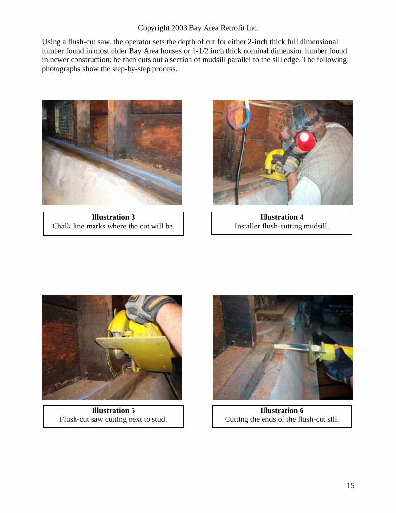
Using a flush-cut saw, the operator sets the depth of cut for either 2-inch thick full dimensional lumber found in most older Bay Area houses or 1-1/2 inch thick nominal dimension lumber found in newer construction; he then cuts out a section of mudsill parallel to the sill edge. The following photographs show the step-by-step process.
Illustration 4 Illustration 3 Chalk line marks where the cut will be. Installer flush-cutting mudsill.
Illustration 5 Illustration 6 Flush-cut saw cutting next to stud. Cutting the ends of the flush-cut sill.
15

Copyright 2003 Bay Area Retrofit Inc.
Illustration 7 Chiseling out the cut section of mudsill.A yellow painted hammer doesn’t getlost under a house as easily as anunpainted one.
Illustration 8 Section of mudsill removed, viewed from
the left end of the cut.
Illustration 9 Section of mudsill removed, viewed from theright end of the cut. Notice that the studs arenow flush with the edge of the mudsill.
Illustration 10 These removed sections of old growth
redwood have as many as 48 growth rings per inch.
16

Copyright 2003 Bay Area Retrofit Inc.
APA EVALUATION OF THE FOUR METHODS OF RETROFIT SHEARWALL CONSTRUCTION
The APA (American Plywood Association) was asked to evaluate each of the possible four methods of building retrofit shear walls that we have discussed here. A letter from Mr. Tom Skaggs, Ph.D, P.E., Senior Engineer and head of the APA’s Technical Services Division is on the following page.
A P A
The Engineered Wood Association January 13,2003
Dear Mr. Cook:
First, I would like to thank you for allowing me to provide comments on the various different retrofit strategies you and your committee have forwarded to our office. Several of my colleagues are actively involved in the development of building codes and retrofit guidelines. I personally have been involved with the last two cycles of the NEHRP Provisions, which as you probably know, serve as the technical basis to the seismic provisions in the International Building Code. I have been on several committees that have prepared seismic rehabilitation documents, and finally, since coming to APA in 1995, I've been actively involved in seismic testing of wood assemblies, most notably cyclic testing of shear walls. Perhaps your committee will find our opinions helpful in making the final retrofit strategy recommendations. Seismic retrofitting wood structures is an art as much as it is a refined science. Sound structural engineering principles must be followed, as well as a strong knowledge of the behavior of light frame construction. For the contractors implementing the retrofit, clever adaptation of standard details is a must, since practically every retrofit is somewhat unique. All of these points combined make it difficult to rank the retrofit strategies in terms of "best performing". Based on my professional opinion, I would judge the retrofit strategies in the following order, from most preferred to least preferred.
1.) Flush-cut mudsill method 2.) Reverse block method 3.) Stapled blocking method 4.) Nailed blocking method
I have chosen to order the retrofit strategies based on several reasons. First, the flush-cut mudsill and the reverse block method are the closest retrofit strategies to a conventionally built shear wall (or sheathed cripple wall). There has been a long history of successful performance of conventional shear walls. Furthermore, the behavior of these structural elements is better understood with each significant research project that is completed. In the past 8 years, there has been an unprecedented amount of cyclic testing on shear walls by APA and other organizations. The results from these various programs would be more similar to either the flush-cut mudsill or the reverse block method; hence I have a great deal of confidence in either of these methods. I believe the flush cut method would be more practical for most retrofits, but the reverse block method would be an acceptable alternative. In my experience of personally working with small blocks of wood in the laboratory as well as small building projects of my own, I believe that multiple nails through the face of the small blocks greatly increase the splitting potential of the small wood blocks. Obviously if the blocks split for either the nailed or stapled blocking method, the structural integrity of the retrofit will be compromised. Nails tend to split wood worse than staples. Therefore, I believe the stapled block method is preferred over the nailed blocking method. An alternative to either of these methods might be to use 1/4" self-drilling/self tapping lag screws.
17

Copyright 2003 Bay Area Retrofit Inc.
In summary, on paper, all of the retrofit strategies are acceptable- Since APA has not, and has no plans to conduct testing of these retrofit strategies; engineering judgment based on experience can be used to rank the different methods. I am of the opinion that my itemized list above is a reasonable ranking of the four methods.
I hope you find this information useful and if you have any questions, or would like to discuss this further, please don't hesitate to contact me.
Sincerely, THOMAS D. SKAGGS, Ph.D., P.E.
Senior Engineer, Technical Services Division
7011 South 19th Street • P.O. Box 11700 • Tacoma, WA 98411-0700 Telephone: (253) 565-6600 • Fax Number: (253) 565-7265uuu
18