Embed Size (px)
Citation preview
#570000The most economical unit toEvacuate,Leak Test & RefillEngine Cooling System!
Powered by the award-winning AIRLIFTTM Technology!
Made in Canada #98072800 Rev.0.3
UView Ultraviolet Systems Inc.1324 Blundell Road, Mississauga,
Ontario Canada L4Y 1M5Toll Free: 1 (877) 776-8486 Phone: 1 (905) 615-8620
Fax: 1 (905) 615-9745
Email: [email protected]

WARNING!
ENGINE COOLING
INDEX
CONTROL LOCATIONS....................................................................................................................... 1
REMOVE COOLANT FROM AN OPEN COOLING SYSTEM ............................................................. 2
REMOVE COOLANT FROM A HOT SYSTEM .................................................................................... 3
DRAFT EFFECT PROCEDURE ........................................................................................................... 4
REMOVE COOLANT FROM OVERFLOW TANK ............................................................................... 4
EVACUATE AIR FROM COOLING SYSTEM ...................................................................................... 5
TEST VACUUM .................................................................................................................................... 5
FILL NEW COOLANT INTO COOLING SYSTEM ............................................................................... 6
STOP FILLING COOLANT .................................................................................................................. 6
DRAIN TO RESERVOIR TANK ........................................................................................................... 7
REUSE COOLANT .............................................................................................................................. 7
REPLACEMENT & ADD ON PARTS.................................................................................................... 8
• Hot antifreeze/coolant under pressure. Wear safety shield and protective clothing (user and bystanders). Do not open system when hot. Read and follow instructions. Hot, pressurized antifreeze/coolant can cause injury.
• Moving engine components. Wear safety goggles (user and bystanders). Keep self and tools clear of moving parts. Moving components can cause injury.
• Engine exhaust contains toxic gases. Vent exhaust away from work area. Do not breathe exhaust. Exhaust gases can cause injury.
WARRANTY
UView Ultraviolet Systems Inc. warrants its products to be free of defects in materials and workmanship for a period of one Year.
UView Ultraviolet Systems Inc., at its sole discretion, will replace or repair any defective item within the Warranty period. UView Ultraviolet Systems Inc. must be contacted in the event of a warranty claim and UView Ultraviolet Systems Inc., at its sole discretion, will decide if the item needs to be returned for inspection. If the item is to be returned for inspection, a Returned Goods Authorization Number (RGA) and shipping instructions will be provided. All returns must be clearly marked with the RGA number provided.
UView Ultraviolet Systems Inc. products can normally be serviced “in field” and will not require return. A replacement part can be sent from the Factory for such repair.
Please contact our Customer Service Department.Toll Free: 1 (877) 776-8486

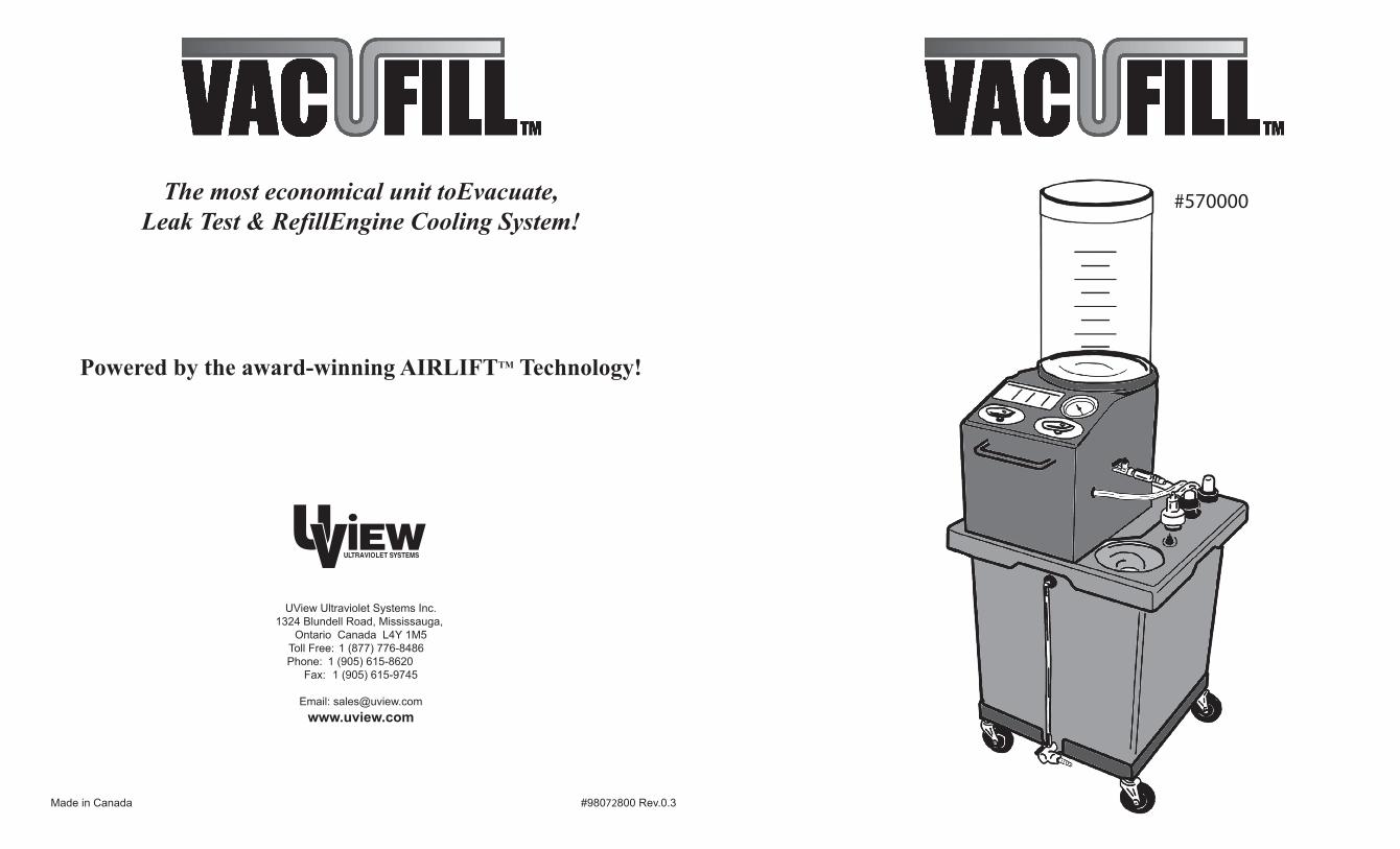
Fill Tank
Gauge
Air Nipple (Not Included)
Rubber Adapters RadNeck Assembly
RecoveryTank
Reservoir Tank
Drain Valve (Reservoir Tank)
REMOVEB
DRAIN TO RESERVOIR
A
VALVE 1
FILLE
TEST
DREMOVE
C
CONTROL LOCATIONS 8 1
98064950
WHEEL
FILL TANK COVER RUBBERADAPTERS (4)
RING STOPPER
9806775057001500
RAD NECK
PARTS for FILL TANK
MISCELLANEOUS PARTS
ADAPTERS/STOPPERS
EXTENSION TUBE ASSEMBLY
98063000 98063150 98063300
OPTIONAL ADD-ON57000500
REUSE COOLANT FILTER
FILL TANK FILTER FILL TANK
9807120055005350
REPLACEMENT PARTS
VALVE 2
VALVE 3

TO REUSE COOLANT1. Cooling System must be in vacuum. See "EVACUATE AIR" instructions.
2. Set to "OFF" .
3. Set to "REMOVE" and to "REMOVE" positions.
4. Let coolant fill Cooling System until vacuum gauge stops. NOTE: Extraction Straw is not used.
Remove RadNeck assembly to check level of coolant.
6. If more coolant is required, follow "EVACUATE AIR" instructions.
Follow "FILL NEW COOLANT" instructions.
TO DRAIN TO RESERVOIR TANK1. Set to "OFF" .
2. Set to "DRAIN TO RESERVOIR" and to "TEST" to drain removed coolant from Recovery Tank to Reservoir Tank.
3. Let coolant continue to drain until Recovery Tank is empty or Reservoir Tank is full. This will take approximately 5 minutes for 2.5 gallons (9.5 L).
4. Set to "REMOVE" position to stop draining.
REMOVE COOLANT FROM AN OPEN COOLING SYSTEM
Operating Temperature (minimum 140 oF/60 oPressurized Tank Cap off.
Connect Air Line (minimum 90 PSI) to Air Valve on unit. Air Valve must be
2. Disconnect RadNeck Assembly from extraction hose. For all horizontal / vertical radiators and side tanks, an Extension Tube Assembly (rigid 3/8” O.D. with Cone) must be added to the extraction hose to remove coolant (when applicable). Place Extension Tube Assembly into radiator or side tank until it reaches the bottom. If tube does not reach bottom of the tank, then slide Cone up or down until it reaches the bottom. ( Figure 1)
4. Attach extraction hose to Extension Tube Assembly or RadNeck Assembly to radiator opening or side tank using the appropriate rubber adaptor, tighten the knurl body by turning it clockwise until snug to ensure fit to radiator neck (only for RadNeck Assembly). ( Figure 3)
6. Push down only on Extension Tube Assembly until vacuum gauge starts to climb to secure cone in place.
10. To release vacuum in system for repairs, disconnect coupler on extraction hose from Extension Tube assembly or RadNeck Assembly. (Figure 4)
"OFF". (Figure 2)NOTE: Clamp off any overflow hoses to get maximum vacuum.
Air Nipple not included.
Set to "REMOVE" and to "REMOVE" and to "ON" .
NOTE:
On some vehicles, the ignition must be on and the heater set on high.
engine block.
assembly extraction hose. (5 minutes)
Set to "TEST" and to "OFF" .
NOTE: It is important to follow the above steps in the exact order.
If is turned "OFF" before is in "TEST" position, coolant will flow back into the vehicle.
additional coolant can be removed using "Draft Effect" instructionson page 4.
Figure 2
D
AIR NIPPLE(Not Included)
AIR LINEVALVE 1 VALVE 2
VALVE 3B C
VVALVE 3
VALVE 3
AIR FILTER
2 7
VALVE 3
VALVE 1
VALVE 1
D
B
A
VALVE 3VALVE 2
VALVE 2
D
VALVE 2
"OFF"VALVE 3
VALVE 1TEST
D
VALVE 2
A
"OFF"REMOVEB C
REMOVE
VALVE 3
VALVE 1 VALVE 2B C
DRAIN TO RESERVOIR
VALVE 1 VALVE 2
VALVE 3
Figure 3
EXTENSIONTUBE
ASSEMBLY
EXTRACTION HOSE
RADNECKASSEMBLY
Figure 1
EXTENSIONTUBE
ASSEMBLY
EXTRACTION HOSE
RADNECKASSEMBLY
EXTENSIONTUBE
ASSEMBLY
Figure 4
RADNECKASSEMBLY
EXTRACTION HOSE

TO STOP FILLING COOLANT When the vacuum gauge reading stops, set to "TEST" position. For side tank vehicles, fill coolant to proper level before setting valves.NOTE: If gauge reading continues to drop and the container is almost empty, add more coolant to the containeruntil the gauge reading stops.
2. Remove RadNeck assembly from cooling system.
3. Top-up cooling system to proper level.
4. Start vehicle to warm up cooling system. Add coolant if necessary before replacing cap for the cooling system.
TO FILL NEW COOLANT INTO COOLING SYSTEM Vehicle cooling system must be evacuated. See "TO EVACUATE AIR" instructions.
1. Fill clear container with the recommended coolant for the vehicle. NOTE: Make sure there is more coolant in the container than the system requires.
coolant into the clear container.
Set to "REMOVE" and to "OFF" .
Set to "FILL". The gauge will start to drop as coolant flows into the cooling system.
Radiator is full when the gauge stops. For vehicles with side tanks, stop when proper fluid levelis reached.
REMOVE COOLANT FROM HOT SYSTEMSCooling systems run at high temperature and pressures. Pressure must be relieved before removing cooling system cap.
Determine if the overflow nipple fits a 5/16" or 3/8" size hose. (Figure 5)
end to the overflow nipple with clamp. (Figure 6)
(Figure 7)
Set to "REMOVE" and to "REMOVE"
and to "ON" (airline is already attached to VACUFILL).
Vacuum gauge will start to rise and coolant will flow into hose.
cap at this time). This will allow more coolant to flow into the VACUFILL.
Once coolant has stopped flowing, turn to "TEST" then to "OFF" position.
removal of the cooling system cap. (Figure 7)
reconnect overflow coolant hose.
11. Now follow the instructions for "Removing Coolant from an Open System".
WARNING! Gloves and protective eyewear must be worn. Risk of burns may result from high coolant temperatures and pressures.
6 3
Figure 6
Figure 7
B
D
EXTRACTION HOSE
Figure 5 OVERFLOWHOSE
OVERFLOWNIPPLE
COUPLER CONNECTION
D
E
VALVE 1
VALVE 2
VALVE 2
B
REMOVEB
VALVE 1 VALVE 2
"OFF"VALVE 3
FILLE
"OFF"REMOVEB
TEST
D
VALVE 3
VALVE 1
VALVE 3
VALVE 3
VALVE 2
VALVE 2
VALVE 1 VALVE 2
VALVE 3
C
OVERFLOWEXTRACTION HOSE
OVERFLOWEXTRACTION HOSE
1. Disconnect the Extension Tube Assembly or RadNeck Assembly from the extraction hose via the coupler connection. ( Figure 4)
EXTENSIONTUBE
ASSEMBLY
Figure 4
RADNECKASSEMBLY
EXTRACTION HOSE

TO TEST VACUUM1. The air in the radiator must be evacuated. (See instructions above).
2. After one minute, set to "TEST", set to "OFF" . 3. Observe gauge for 20 seconds for any drop in vacuum. No drop in vacuum means no leaks.
If there is no vacuum loss then proceed with filling the cooling system.NOTE: Fill cooling system with proper coolant as per manufacturer’s specifications.
TO EVACUATE AIR FROM COOLING SYSTEMAttach and secure RadNeck assembly to cooling system.
Clamp off over-flow hoses to get a vacuum in the cooling system.
Attach air-line hose to .
Set to "REMOVE" and to "REMOVE" and to "ON" .
If vehicle is warm, the gauge will show a vacuum reading of 15 (Minimum). If the vehicle is cold then a higher reading will show between 15-26.
REMOVE COOLANT FROM OVERFLOW TANK
1. Set to "REMOVE" and to "REMOVE" and to "ON" .
There will be a hissing sound from the Coolant Changer system.
Repeat Steps 8 to 10 (Pg. 2) to remove coolant.
4 5
Figure 10
HEATER HOSE
HEATER CORE
Disconnect Here
DRAFT EFFECT PROCEDUREThis procedure is performed once the open system procedure is completed to maximize coolant removal.
Remove heater hose at heater core leading to the water pump. (Figure 10)Plug or pinch off the removed hose using appropriate tools (pinch-off pliers or heater core plugs).
Temporarily plug heater core using heater core plug (not included).
Draw system down to 24-26 inches of vacuum.
Remove the temporary plug from the heater core.
core and engine block into the radiator.
For best results, repeat this procedure until no more coolant is extracted.
down to 24-26 inches of vacuum
Set to "TEST" to check cooling system for any vacuum leaks.
VALVE 1
VALVE 2
VALVE 2 VALVE 3
VALVE 3
VALVE 3VALVE 1 VALVE 2
VALVE 2 VALVE 3
B
B
C
C
D
D
"ON"
"OFF"VALVE 3
VALVE 3
REMOVEB
TEST
D
VALVE 1
REMOVEB C
REMOVE
VALVE 2
VALVE 1 VALVE 2An Extension Tube Assembly is needed to remove coolant from Overflow tanks. The tube in the Extension tube Assembly should reach the bottom of an Overflow tank. If not, then slide the Cone up the tube until it reaches the bottom.
1. Disconnect the Extension Tube Assembly or RadNeck Assembly from the extraction hose via the coupler connection. ( Figure 9)
EXTENSIONTUBE
ASSEMBLY
Figure 9
RADNECKASSEMBLY
EXTRACTION HOSE


![WELCOME! [railroads.dot.gov]...LT Operator Training 16 Leak Testing technique must be of proper sensitivity for scope of test, and also be economical value for the technique to be](https://img.pdfslide.us/doc/110x75/5ed4c969fd1f950b814dfbe9/welcome-lt-operator-training-16-leak-testing-technique-must-be-of-proper.jpg)