Embed Size (px)
Citation preview
C o l l o q u i u m 19-20 April 2011
Institute for Microstructural and Mechanical Process Engineering: The University of Sheffield
INTRODUCTION
The authors gratefully acknowledge the Ministry of National Education of Indonesian Government and Institut Teknologi Nasional Bandung for their financial support
The microstructure evolution of hot work tungsten tool steel during conventional heat treatment
M. Nurbanasari, P. Tsakiropoulos, and E.J. Palmiere
Hot work tungsten tool steels (Group H) are developed to meet the industrial need for materials with good mechanical properties for forming operations at high working temperature. These steels are highly alloyed specially with tungsten and chromium which affects the volume fraction and nature of the carbides. The critical issue of these steels is the low toughness. They are prone to brittleness at normal working temperatures and are inclined to distort during hardening process. The carbides of these steels are very brittle and do not dissolve in austenite by heating. A choice of heat treatment process and their parameter must be considered.
The potential of these steels is:
Resistance to deformation at the elevated working temperature.
High hot hardness,
High compressive strength
Wear resistance at elevated temperatures
Resistance to heat checking
Good machinability in the annealed condition
AIM To provide data that would allow the design of tool steels with a balance of satisfactory hardness and toughness.
STRATEGY
Select heat treatment parameters that give combination of satisfactory hardness and toughness Investigate phase transformations during conventional heat treatment process
HOT WORK TUNGSTEN TOOL STEELS
1. The main alloying elements are strong carbide formers [3]
2. Choice of proper heat treatment processes [3]
3. Create secondary hardening (SH) during heat treatment process
Table 2: The chemical composition of investigated hot work tungsten tool steels (%wt):
cavity
10
10
10
Fig 10 :Heat treated sample
Austenizing temperature of both tool steels : 1100, 1250 oC
First and second tempering temperatures respectively of both tool steels: 650, 750, 800oC
Conventional heat treatment process
Fig 11: Schematic of heat treatment process
AIM AND STRATEGY OF PROJECT
THE STRENGTHEN OF TOOL STEEL
REFERENCES
HARDNESS AND XRD RESULT
CONCLUSIONS
MICROSTRUCTURE EXPERIMENTAL PROCEDURE
Fig 12: Tempering curve of H21
472
226 214
422
247 236
0
100
200
300
400
500
600 650 700 750 800 850
Har
dn
ess
(V
HN
)
Double tempering (DT) temperature (oC)
austenising temp 1250 oC
austenising temp 1100 oC
413,1
300,5 285,4
257,7 254,5 235,0
0,0
100,0
200,0
300,0
400,0
500,0
600 650 700 750 800 850
Har
dn
ess
(V
HN
)
Double tempering (DT) temperature (oC)
austenising temp 1250 oC
austenising temp 1100 oC
Fig 13 : Tempering curve for H23
Table 3: Hardness of as cast and as quenched condition
The as quenched hardness of H23 is lower than as cast because of absence of martensite The hardness of both tool steel decreased with higher tempering temperatures because the carbide size
became bigger The hardness increased during tempering process due to secondary carbides produced at this condition Higher austenizing temperatures increased the hardness of tempered samples, due to the higher
dissolution of M6C in the austenite matrix
as castas quenched
(Tg 1100 oC)
as quenched
(Tg 1250 oC)H21 483 574 536
H23 356 265 284
Hardness (VHN)Type of
tool steel
As cast condition
Fig 15: SE image of cast H21
Type position V Cr Fe W phase
H21 matrix 0.6±0.4 4.8±1 92±1.5 2.7±0.5 ferrite
carbide 1.5 4.6 64.7 29.3 M6C
H23 matrix 1.1±0.6 13.5±1 79.9±1 5.5±2 ferrite
Carbide 1 3.9 21.2 49.5 25.3 M6C
Carbide 2 2.5 16.2 52.2 29.1 M6C
Table 4: EDS analysis of as cast steels (%wt)
Fig 16 : SE image of as cast H23
Heat treated condition
The primary carbide for both tool steels was M6C and was dominantly located along the grain boundaries
the differences between the composition of the carbides and matrixs refer to the levels of W, Cr, V and mainly Fe
Fig 18 : The microstructural changes of heat treated H21 (etchant 98 % picric acid + 2% HCl)
1. G.A Roberts. G.Krauss, Kennedy. 1998, Tool Steels, 5th edition, ASM, Metals Park, Ohio.
2. G.F. Vander Voort., E.P. Manilova., J.R Michael. 2004, A Study of Selective Etching of Carbides in Steels, Micros. Microanal. 10(suppl 2), 76-77
3. LS.Kremnev. 2008, Alloying Theory and Its Use for Creation of Heat Resistant Tool Steels and Alloys”, Material Science and Heat Treatment, Vol.50, 18-27
4. M. Kroneis. 1979, Tungsten in Steel, in: Proc.1st International Tungsten Symposium, Stockholm, Mining Journals Books, Ltd, London, 96-107
code position V Cr Fe W phase
A1 matrix 0.7 4.0 83.3 12.0 martemper
Carbide 1 1.5 3.1 28.4 67 M6C
Carbide 2 1.1 4.1 46.0 48.8 M6C
D6 matrix 0.7 13.4 78.8 7.1 ferrite
Carbide 1 2.6 10.8 47.8 38.8 M6C
Carbide 2 3.0 38.1 42.3 16.6 M7C3
Carbide 3 3.1 40.0 38.4 18.5 M23C6 Fig 19: BSE images of D6 Fig 20: SE images of A1
Table 5: EDS analysis of some heat treated samples (%wt)
• The highest hardness the H21 tool steel was 472 VHN and of the H23 tool steel was 412 VHN with austenizing temperature 1250 oC and double tempered 650oC
• After double tempered process, some of the carbides were still networked and mainly located along the grain boundaries
• The primary carbide for both tool steel was the M6C and after heat treatment the M7C3 and M23C6 were found in the H23 tool steel as secondary carbides
DH1 :Tg 1250 oC , quenched
D1: Tg 1250 oC, quenched, DT 800 oC
D2: Tg 1250 oC, quenched, DT 750 oC
D3 : Tg 1250 oC, quenched, DT 650 oC
DH2 :Tg 1100 oC , quenched
D4: Tg 1100 oC, quenched, DT 800 oC
D5: Tg 1100 oC, quenched, DT 750 oC
D6: Tg 1100 oC, quenched, DT 650 oC
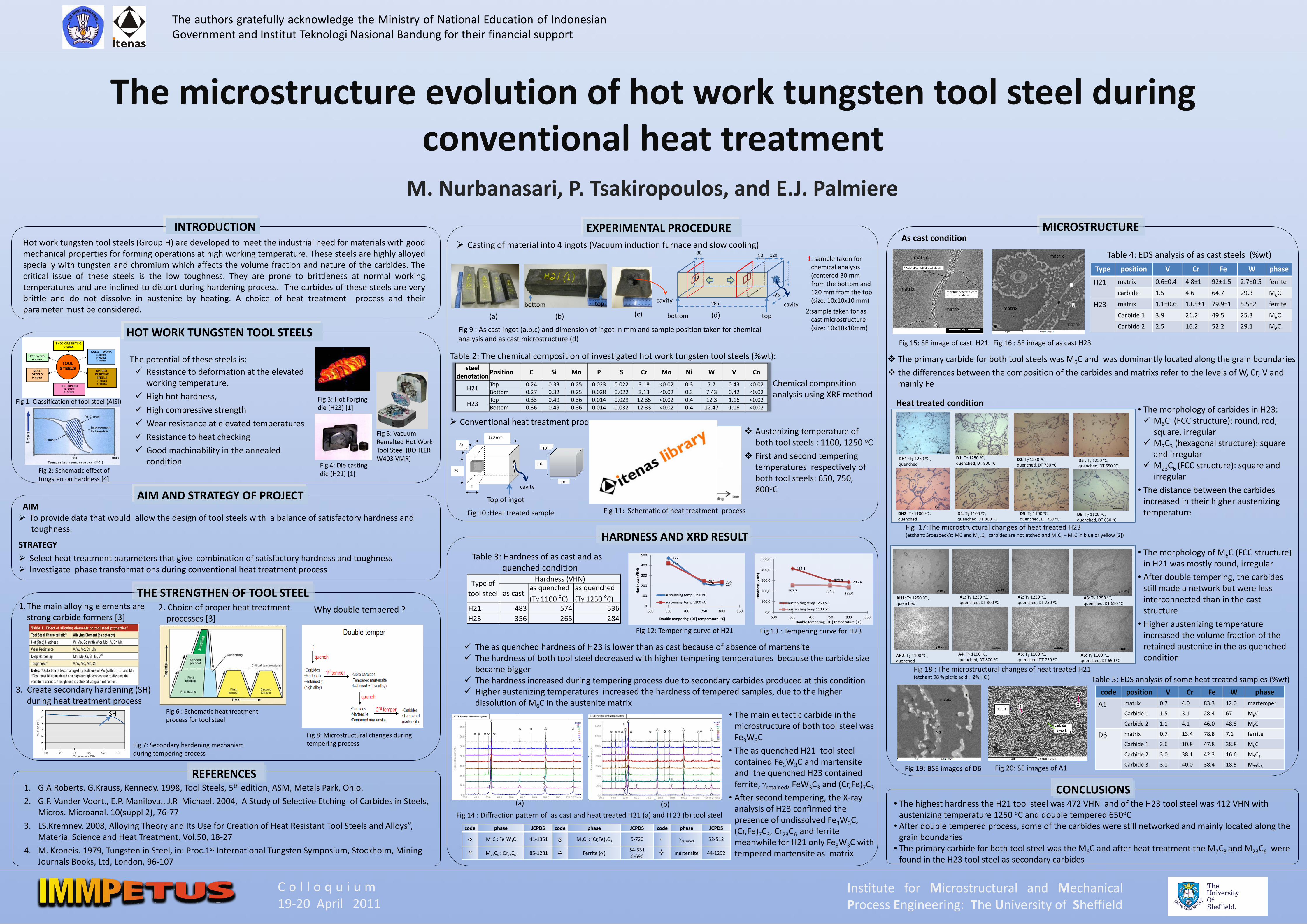
• The morphology of carbides in H23: M6C (FCC structure): round, rod,
square, irregular M7C3 (hexagonal structure): square
and irregular M23C6 (FCC structure): square and
irregular
• The distance between the carbides increased in their higher austenizing temperature
• The morphology of M6C (FCC structure) in H21 was mostly round, irregular
• After double tempering, the carbides still made a network but were less interconnected than in the cast structure
• Higher austenizing temperature increased the volume fraction of the retained austenite in the as quenched condition
AH1: Tg 1250 oC , quenched
A1: Tg 1250 oC, quenched, DT 800 oC
A2: Tg 1250 oC, quenched, DT 750 oC
A3: Tg 1250 oC, quenched, DT 650 oC
AH2: Tg 1100 oC , quenched
A4: Tg 1100 oC, quenched, DT 800 oC
A5: Tg 1100 oC, quenched, DT 750 oC
A6: Tg 1100 oC, quenched, DT 650 oC
Fig 9 : As cast ingot (a,b,c) and dimension of ingot in mm and sample position taken for chemical analysis and as cast microstructure (d)
1: sample taken for chemical analysis (centered 30 mm from the bottom and 120 mm from the top (size: 10x10x10 mm)
2:sample taken for as cast microstructure (size: 10x10x10mm)
Fig 17:The microstructural changes of heat treated H23 (etchant:Groesbeck’s: MC and M23C6 carbides are not etched and M7C3 – M6C in blue or yellow [2])
Fig 14 : Diffraction pattern of as cast and heat treated H21 (a) and H 23 (b) tool steel
(b) (a)
code phase JCPDS code phase JCPDS code phase JCPDS
M6C : Fe3W3C 41-1351 M7C3 : (Cr,Fe)7C3 5-720 gretained 52-512
M23C6 : Cr23C6 85-1281 Ferrite (a) 54-331 6-696
martensite 44-1292
Fig 3: Hot Forging die (H23) [1]
Fig 4: Die casting die (H21) [1]
Fig 5: Vacuum Remelted Hot Work Tool Steel (BOHLER W403 VMR)
Fig 1: Classification of tool steel (AISI)
Fig 6 : Schematic heat treatment process for tool steel
Fig 7: Secondary hardening mechanism during tempering process
Fig 2: Schematic effect of tungsten on hardness [4]
• The main eutectic carbide in the microstructure of both tool steel was Fe3W3C
• The as quenched H21 tool steel contained Fe3W3C and martensite and the quenched H23 contained ferrite, gretained, FeW3C3 and (Cr,Fe)7C3
• After second tempering, the X-ray analysis of H23 confirmed the presence of undissolved Fe3W3C, (Cr,Fe)7C3, Cr23C6 and ferrite meanwhile for H21 only Fe3W3C with tempered martensite as matrix
Why double tempered ?
Fig 8: Microstructural changes during tempering process
Chemical composition analysis using XRF method
Casting of material into 4 ingots (Vacuum induction furnace and slow cooling)
1 1 2
SH
(a) (b) (c) (d)
75
10
70
120 mm
Top of ingot
cavity
10 30
120
285 cavity
2
top bottom
bottom top
steel denotation
Position C Si Mn P S Cr Mo Ni W V Co
H21 Top 0.24 0.33 0.25 0.023 0.022 3.18 <0.02 0.3 7.7 0.43 <0.02 Bottom 0.27 0.32 0.25 0.028 0.022 3.13 <0.02 0.3 7.43 0.42 <0.02
H23 Top 0.33 0.49 0.36 0.014 0.029 12.35 <0.02 0.4 12.3 1.16 <0.02 Bottom 0.36 0.49 0.36 0.014 0.032 12.33 <0.02 0.4 12.47 1.16 <0.02
matrix
matrix
matrix
matrix
matrix
matrix