Embed Size (px)
Citation preview
THE METHOD OF DETERMINING HORIZONTAL
CURVATURE IN GEOMETRICAL LAYOUTS OF
RAILWAY TRACK WITH THE USE OF MOVING CHORD
W. KOC1
In the paper, the issue of determining the horizontal curvature of the railway track axis was discussed to define
unknown geometric characteristics of the measured route (location of straight and arched sections, circular arc radii,
transition curve lengths, etc.). This problem has not been solved yet, and so far geometrical characteristics have been
identified by approximate methods (e.g. horizontal arrow chart). Operating the angles of tangent to the geometrical
layout (resulting from the very definition of curvature) seems very difficult in a real railway track reproduced on the
basis of measurements. Therefore, a new concept has emerged to determine the curvature of the track not with the use
of tangent but corresponding chords. In this way, the idea of curvature determination using the method of changing the
slope angles of the moving chord was developed. Verification of the proposed method, carried out on a clearly defined
basic geometric system of tracks, showed a sufficient compliance of the obtained curvature charts with the charts of the
corresponding geometric solution. In order to use this method, one must know the coordinates of the points of a given
section of the route in the Cartesian system.
Keywords: Track Geometry, Horizontal Curvature, Use of Moving Chord, Verification of a New Method
1 Prof., DSc., PhD., Eng., Gdańsk University of Technology, Faculty of Civil and Environmental Engineering, ul. G. Narutowicza 11/12, 80-233 Gdańsk, Poland, e-mail: [email protected]
1. INTRODUCTION
The geometrical shape of the railway track plays a key role in the safety of rail transport. The
designation and assessment of the shape of the track axis in the horizontal plane, determining the
possible train speed, is of particular importance here. The purpose of this operation is to define the
basic geometric parameters of the route:
� location and length of straight sections,
� location of circular arcs together with their radius and length,
� location of transition curves with specification of their type and length.
Basing on this data, it becomes possible to simulate the train passing in a given geometrical layout
(and thus determining the speed), as well as to obtain data for designing the track axis adjustment,
which seems to be the fundamental issue.
The present measuring methods have a very long tradition and although they are subject to
various innovations, they are characterized by high labour intensity and the associated necessity to
incur significant financial outlays. The rules for performing measurements are similar in different
railway managements [1-6]. In accordance with the provisions in force in Poland [7], straight
sections are measured using the ordinate and abscissa method along the measuring lines, with an
appropriate geodetic matrix. The measurements on the arc include the measurement of horizontal
arrows related to the chord determined by the theodolite target axis (the so-called direct method) or
the track axis adjustment signs (indirect method); measurement accuracy is up to 1 mm.
A more modern measuring system is the Total Station placed on a trolley; it allows the
measurement of track inclination (using an inclinometer) and its width. The position is determined
by indenting back to four geodetic network points (with reference to the 1st class state surveying
grid). Coordinates are measured at intervals of 10 m on straight sections and every 5 m on sections
located in the arc, in relation to the point on the inside of the head of the right rail track.
A major improvement of the existing situation should be ensured by the mobile satellite
measurement method developed in Poland 10 years ago [8-10]. It involves continuous registration
of track axis coordinates using GNSS receivers installed on a moving flat car. It also means using
collected measurement data in appropriate calculation algorithms (so-called analytical design
method [11-12]). The advantages of this method have been recognized by the national infrastructure
580 W. KOC
manager – PKP Polskie Linie Kolejowe S. A. It was proved in the launch of the BRIK research
project [13], which aims to achieve a practical solution.
The number of track axis coordinates obtained in mobile satellite measurements depends on the
speed of the measurement flat car and the frequency of receivers used. For example, for a speed of
20 km/h and 20 Hz antenna frequency, the distance between the measuring points is 28 cm;
measuring a distance of 1 km takes 3 minutes. These are, therefore, best values compared to other
methods.
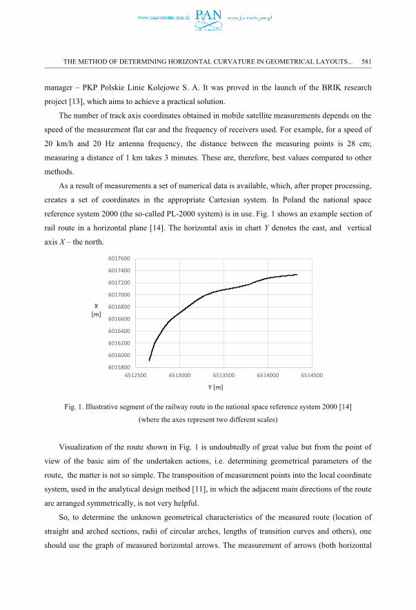
As a result of measurements a set of numerical data is available, which, after proper processing,
creates a set of coordinates in the appropriate Cartesian system. In Poland the national space
reference system 2000 (the so-called PL-2000 system) is in use. Fig. 1 shows an example section of
rail route in a horizontal plane [14]. The horizontal axis in chart Y denotes the east, and vertical
axis X – the north.
Fig. 1. Illustrative segment of the railway route in the national space reference system 2000 [14]
(where the axes represent two different scales)
Visualization of the route shown in Fig. 1 is undoubtedly of great value but from the point of
view of the basic aim of the undertaken actions, i.e. determining geometrical parameters of the
route, the matter is not so simple. The transposition of measurement points into the local coordinate
system, used in the analytical design method [11], in which the adjacent main directions of the route
are arranged symmetrically, is not very helpful.
So, to determine the unknown geometrical characteristics of the measured route (location of
straight and arched sections, radii of circular arches, lengths of transition curves and others), one
should use the graph of measured horizontal arrows. The measurement of arrows (both horizontal
6015800
6016000
6016200
6016400
6016600
6016800
6017000
6017200
6017400
6017600
6512500 6513000 6513500 6514000 6514500
X [m]
Y [m]
THE METHOD OF DETERMINING HORIZONTAL CURVATURE IN GEOMETRICAL LAYOUTS... 581
and vertical) has for many years been the basis for diagnostic methods relating to the assessment of
the geometrical condition of railway tracks [15-17]. Another approximate method is the so-called
"curvature chart" built in an approximate way – on circles designated by three points located along
the track. To improve the existing situation a solution consisting in determining the curvature of the
geometric layout seems to be the first thing that comes to one’s mind in this situation.
2. DEFINING THE TRACK CURVATURE
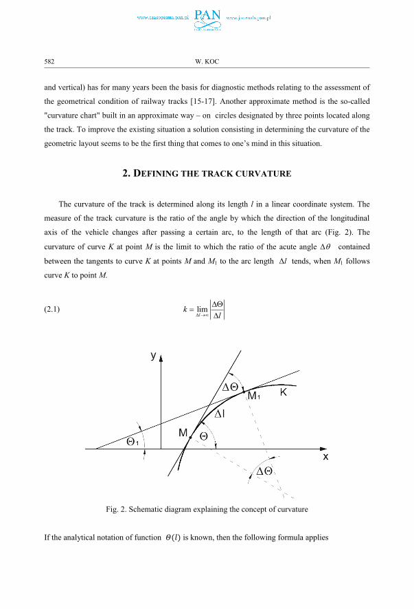
The curvature of the track is determined along its length l in a linear coordinate system. The
measure of the track curvature is the ratio of the angle by which the direction of the longitudinal
axis of the vehicle changes after passing a certain arc, to the length of that arc (Fig. 2). The
curvature of curve K at point M is the limit to which the ratio of the acute angle Δ� contained
between the tangents to curve K at points M and M1 to the arc length Δl tends, when M1 follows
curve K to point M.
(2.1) liml
kl� ��
���
�
Fig. 2. Schematic diagram explaining the concept of curvature
If the analytical notation of function is known, then the following formula applies
582 W. KOC
(2.2) ( ) ( )dk l ldl
� �
Based on formula (2.1), it is very easy to determine the curvature for a circular arc (i.e. a circle)
with radius R. The angle Δ� here is equal to the angle between the radiuses reaching the contact
points, which leads to obtaining a constant curvature k = 1/R, expressed in (rad/m).
The issue of determining curvature on sections with variable curvature (i.e. on transition
curves) is much more complex. However, there is no reason to treat any curve as a series of circular
arcs with a changing radius (which is widely practiced). The curvature distribution should be
formed here along the length of the curve for variable l. It also applies to the railway track
deformed by frequent use (as in Fig. 1).
Designing a geometric system, however, requires operating in a Cartesian coordinate system.
As a result of this process, the track axis coordinates are determined, allowing it to be delineated on
site. Determining the curvature of a given geometrical layout is therefore difficult because direct
use of formulas from a linear system is impossible.
3. THE IDEA OF THE PROPOSED METHOD OF CHANGING THE
INCLINATION ANGLES OF THE MOVING CHORD
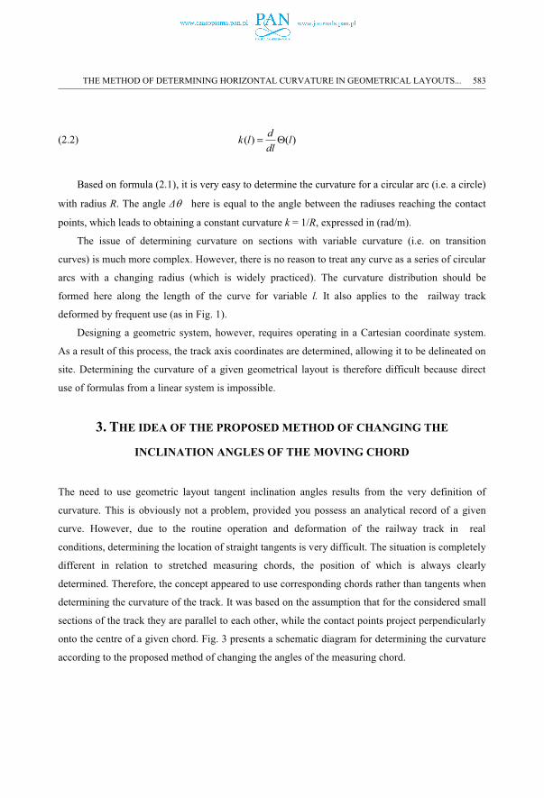
The need to use geometric layout tangent inclination angles results from the very definition of
curvature. This is obviously not a problem, provided you possess an analytical record of a given
curve. However, due to the routine operation and deformation of the railway track in real
conditions, determining the location of straight tangents is very difficult. The situation is completely
different in relation to stretched measuring chords, the position of which is always clearly
determined. Therefore, the concept appeared to use corresponding chords rather than tangents when
determining the curvature of the track. It was based on the assumption that for the considered small
sections of the track they are parallel to each other, while the contact points project perpendicularly
onto the centre of a given chord. Fig. 3 presents a schematic diagram for determining the curvature
according to the proposed method of changing the angles of the measuring chord.
THE METHOD OF DETERMINING HORIZONTAL CURVATURE IN GEOMETRICAL LAYOUTS... 583
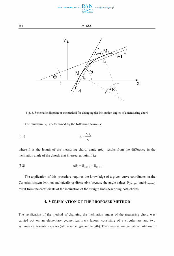
Fig. 3. Schematic diagram of the method for changing the inclination angles of a measuring chord
The curvature ki is determined by the following formula:
(3.1) ii
c
kl��
�
where lc is the length of the measuring chord, angle results from the difference in the
inclination angle of the chords that intersect at point i, i.e.
(3.2) ( 1) ( 1)i i i i i � �� �� ��
The application of this procedure requires the knowledge of a given curve coordinates in the
Cartesian system (written analytically or discretely), because the angle values and
result from the coefficients of the inclination of the straight lines describing both chords.
4. VERIFICATION OF THE PROPOSED METHOD
The verification of the method of changing the inclination angles of the measuring chord was
carried out on an elementary geometrical track layout, consisting of a circular arc and two
symmetrical transition curves (of the same type and length). The universal mathematical notation of
584 W. KOC
such a layout is presented in [11]. As part of the verification, many cases were considered for
different train speeds, with different types of transition curves and route diversion angles used. Two
types of transition curves were used:
� the clothoid commonly used on railroad, described by parametric equations
(4.1) 5 9 132 2 4 4 6 6
1 1 1( )40 3456 599040k k k
x l l l l lR l R l R l
� � �
(4.2) 3 7 113 3 5 5
1 1 1( )6 336 42240k k k
y l l l lRl R l R l
� �
� the new transition curve proposed in [18], described by parametric equations
(4.3) 5 6 7 8 92 2 2 3 2 4 2 5 4 4 2 6
1 1 5 1 1 1( )40 36 504 96 3456 288k k k k k k
x l l l l l l lR l R l R l R l R l R l
� � � � � � �
� �
10 11 124 5 4 6 4 7
1 1 191440 6336 31104k k k
l l lR l R l R l
�
(4.4) 3 4 5 7 8 92 3 3 3 3 4 3 5
1 1 1 1 1 1( )6 12 20 336 192 2592k k k k k k
y l l l l l l lRl Rl Rl R l R l R l
� � � �
10 11 123 6 5 5 3 7 5 6 3 8
69 1 1 1 119440 42240 6336 13824 1152k k k k k
l l lR l R l R l R l R l
� � � �� � � �
� � � �
In the analytical design method [11], the area of a circular arc is described by an explicit
function y(x). In the case of transition curves, the applied procedure allows to operate with the
parametric equations x(l) and y(l) (as in this paper), as well as with the equations y(x). The latter
mainly relate to roads [19-23].
The course of proceedings consists of two main stages. First, the coordinates of successive
points of the curve, separated from each other by lc (i.e. the length of the chord, in a straight line)
are determined. As part of the verification, lc = 5 m was adopted and, due to the symmetry of the
geometric layout, the procedure started from the point located in the centre of the layout (i.e. on the
circular arc), first dealing with the right side of the system (Fig. 4). Next, like in the mirror image,
the required data for the left side of the system was completed.
THE METHOD OF DETERMINING HORIZONTAL CURVATURE IN GEOMETRICAL LAYOUTS... 585
In the second stage, the curvature of the track axis is determined. The main focus is on
determining angles ( 1)i i� � and ( 1)i i � . To do this, first determine the inclination coefficients of
both chords in contact, using the following formulas:
(4.5) 1( 1)
1
i ii i
i i
y ysx x
��
�
��
�
(4.6) 1( 1)
1
i ii i
i i
y ysx x
��
�
Because ( 1) ( 1)arctani i i is� � � � , and ( 1) ( 1)arctani i i is � � , formula (3.2) may be applied and the
curvature may be established using formula (3.1).
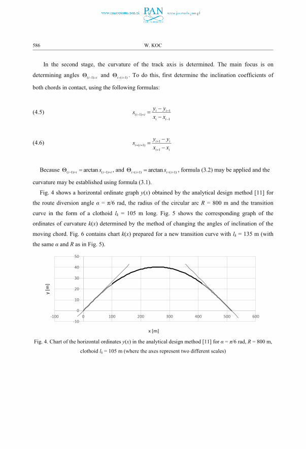
Fig. 4 shows a horizontal ordinate graph y(x) obtained by the analytical design method [11] for
the route diversion angle α = π/6 rad, the radius of the circular arc R = 800 m and the transition
curve in the form of a clothoid lk = 105 m long. Fig. 5 shows the corresponding graph of the
ordinates of curvature k(x) determined by the method of changing the angles of inclination of the
moving chord. Fig. 6 contains chart k(x) prepared for a new transition curve with lk = 135 m (with
the same α and R as in Fig. 5).
Fig. 4. Chart of the horizontal ordinates y(x) in the analytical design method [11] for α = π/6 rad, R = 800 m,
clothoid lk = 105 m (where the axes represent two different scales)
-10
0
10
20
30
40
50
-100 0 100 200 300 400 500 600
y [m
]
x [m]
586 W. KOC
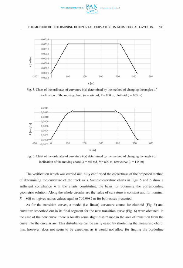
Fig. 5. Chart of the ordinates of curvature k(x) determined by the method of changing the angles of
inclination of the moving chord (α = π/6 rad, R = 800 m, clothoid lk = 105 m)
Fig. 6. Chart of the ordinates of curvature k(x) determined by the method of changing the angles of
inclination of the moving chord (α = π/6 rad, R = 800 m, new curve lk = 135 m)
The verification which was carried out, fully confirmed the correctness of the proposed method
of determining the curvature of the track axis. Sample curvature charts in Figs. 5 and 6 show a
sufficient compliance with the charts constituting the basis for obtaining the corresponding
geometric solution. Along the whole circular arc the value of curvature is constant and for nominal
R = 800 m it gives radius values equal to 799.9987 m for both cases presented.
As for the transition curves, a model (i.e. linear) curvature course for clothoid (Fig. 5) and
curvature smoothed out in its final segment for the new transition curve (Fig. 6) were obtained. In
the case of the new curve, there is locally some slight disturbance in the area of transition from the
curve into the circular arc. This disturbance can be easily eased by shortening the measuring chord;
this, however, does not seem to be expedient as it would not allow for finding the borderline
-0,0002
0,0000
0,0002
0,0004
0,0006
0,0008
0,0010
0,0012
0,0014
-100 0 100 200 300 400 500 600
k [r
ad/m
]
x [m]
-0,0002
0,0000
0,0002
0,0004
0,0006
0,0008
0,0010
0,0012
0,0014
-100 0 100 200 300 400 500 600
k [r
ad/m
]
x [m]
THE METHOD OF DETERMINING HORIZONTAL CURVATURE IN GEOMETRICAL LAYOUTS... 587
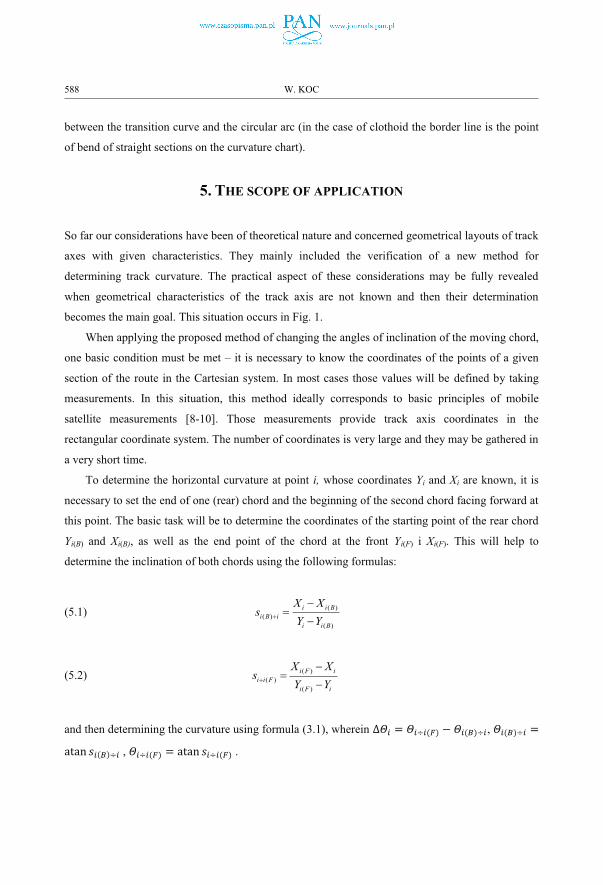
between the transition curve and the circular arc (in the case of clothoid the border line is the point
of bend of straight sections on the curvature chart).
5. THE SCOPE OF APPLICATION
So far our considerations have been of theoretical nature and concerned geometrical layouts of track
axes with given characteristics. They mainly included the verification of a new method for
determining track curvature. The practical aspect of these considerations may be fully revealed
when geometrical characteristics of the track axis are not known and then their determination
becomes the main goal. This situation occurs in Fig. 1.
When applying the proposed method of changing the angles of inclination of the moving chord,
one basic condition must be met – it is necessary to know the coordinates of the points of a given
section of the route in the Cartesian system. In most cases those values will be defined by taking
measurements. In this situation, this method ideally corresponds to basic principles of mobile
satellite measurements [8-10]. Those measurements provide track axis coordinates in the
rectangular coordinate system. The number of coordinates is very large and they may be gathered in
a very short time.
To determine the horizontal curvature at point i, whose coordinates Yi and Xi are known, it is
necessary to set the end of one (rear) chord and the beginning of the second chord facing forward at
this point. The basic task will be to determine the coordinates of the starting point of the rear chord
Yi(B) and Xi(B), as well as the end point of the chord at the front Yi(F) i Xi(F). This will help to
determine the inclination of both chords using the following formulas:
(5.1) ( )( )
( )
i i Bi B i
i i B
X Xs
Y Y
��
�
(5.2) ( )( )
( )
i F ii i F
i F i
X Xs
Y Y
��
�
and then determining the curvature using formula (3.1), wherein ,
, .
588 W. KOC
Mobile satellite measurements also create other, additional opportunities. When operating a
measuring flat car with two satellite receivers installed on bogie kingpins, satellite antennas
basically define the measuring chord; the method of changing the inclination angle of the chord for
determining the curvature becomes even more effective.
6. CONCLUSIONS
The basis for determining the geometrical characteristics of the measured railway route should be
its horizontal curvature. The fact that it is necessary to use angles of tangent inclination to the
geometric system results from the definition of curvature. In a real railway track, recreated on the
basis of measurements, defining the location of straight tangents appears to be very difficult.
Therefore, the concept appeared not to use tangents but corresponding measuring chords when
determining the curvature of the track. It was assumed that for the considered small sections of the
track they are parallel to each other. In this way, the idea of curvature determination using the
method of changing the angles of the chord was created.
The verification of the proposed method was carried out on a clearly defined elementary
geometrical layout of tracks, consisting of a circular arc and two symmetrically set transition curves
(of the same type and length), calculated according to the principles of the analytical design method
[11]. A number of geometrical cases were considered, achieving sufficient compliance of the
obtained curvature charts with the charts constituting the basis for obtaining the corresponding
geometric solution. This concerned both sections of the circular arc as well as sections of transition
curves.
The proposed method creates a great range of applications. The practical aspect of the
presented considerations may be revealed when the geometrical characteristics of the track axis
determined by measurements are not known and then the basic goal will be to find them out. In this
situation, the discussed method ideally corresponds to mobile satellite measurements. These
measurements define a great number of track axis coordinates in a rectangular coordinate system in
a very short time.
REFERENCES
1. “British railway track design, construction and maintenance, 6th ed.”, London, UK: The Permanent Way Institution, 1993.
2. ”Railway applications—Track—Track alignment design parameters—Track gauges 1435 mm and wider—Part 1: Plain line. EN 13803-1”, Brussels, Belgium: CEN (European Committee for Standardization), 2010.
THE METHOD OF DETERMINING HORIZONTAL CURVATURE IN GEOMETRICAL LAYOUTS... 589
3. ”883.2000 DB_REF-Festpunktfeld”, Berlin, Germany: DB (Deutsche Bahn) Netz AG, 2016. 4. ”Code of federal regulations title 49 transportation”, FRA (Federal Railroad Administration), Washington, DC: US
Government Printing Office, 2008. 5. ”NR/L3/TRK/0030 NR_Reinstatement of Absolute Track Geometry (WCRL Routes), Iss. 1”, London, UK: NR
(Network Rail), 2008.6. ”Standard: Railway Surveying, Version 1.0. T HR TR 13000 ST”, Sydney, Australia: NSW (New South Wales)
Government (Transport for NSW), 2016. 7. PKP (Polish State Railways). 2018. “Standardy Techniczne – Szczegółowe warunki techniczne dla modernizacji lub
budowy linii kolejowych do predkości Vmax 200 km/h (dla taboru konwencjonalnego) / 250 km/h (dla taboru z wychylnym pudłem) – TOM I - DROGA SZYNOWA – Załącznik ST-T1_A6: Układy geometryczne torów”, Warsaw, Poland: PKP Polskie Linie Kolejowe, 2018.
8. W. Koc, C. Specht, ”Selected problems of determining the course of railway routes by use of GPS network solution”, Archives of Transport 23 (3): 303-320, 2011.
9. C. Specht, W. Koc, ”Mobile satellite measurements in designing and exploitation of rail roads”, Transportation Research Procedia 14: 625-634, 2016..
10. C. Specht, W. Koc, P. Chrostowski, J. Szmagliński, ”Accuracy assessment of mobile satellite measurements in relation to the geometrical layout of rail tracks”, Metrology and Measurement Systems 26 (2): 309-321, 2019.
11. W. Koc, ”Design of rail-track geometric systems by satellite measurement”, Journal of Transportation Engineering 138 (1): 114-122, 2012.
12. W. Koc, “Analytical method of modelling the geometric system of communication route”, Mathematical Problems in Engineering 2014: 679817.
13. A. Wilk, C. Specht, W. Koc, K. Karwowski, P. Chrostowski, J. Szmagliński, P. Dąbrowski, M. Specht, S. Judek, J. Skibicki, M. Skóra, S. Grulkowski, ”Research project BRIK: development of an innovative method for determining the precise trajectory of a railway vehicle”, Transportation Oveview – Przegląd Komunikacyjny 74 (7): 32-47, 2019.
14. W. Koc, “The analytical design method of railway route’s main directions intersection area.” Open Engineering6 (1): 1-9, 2016.
15. L. Marx, “Satellitengestützte Gleisvermessung – auch beim Oberbau”, EI – Eisenbahningenieur 58 (6): 9-14, 2007.16. C. Qijin, N. Xiaoji, Z. Lili, Z. Tisheng, X. Fuqin, L. Yi, L. Jingnan, “A railway track geometry measuring trolley
system based on aided INS,”, Sensors 18 (2): 538, 2018.17. Y. Naganuma, T. Yasukuni, T. Uematsu, “Development of an inertial track geometry measuring trolley and
utilization of its high-precision data”, International Journal of Transport Development and Integration 3 (3): 271–285, 2019.
18. W. Koc, ”New transition curve adapted to railway operational requirements”, Journal of Surveying Engineering 145 (3): 04019009, 2019.
19. R. J. Grabowski, ”Kształtowanie geometryczne krzywych przejściowych w drogach kołowych, kolejowych i trasach wodnych”, Rozprawy Naukowe 38, Białystok: Wydawnictwa Politechniki Białostockiej, 1996.
20. A. Kobryń, ”Polynomial solutions of transition curves”, Journal of Surveying Engineering 137(3): 71-80, 2011. 21. A. Kobryń, “New solutions for general transition curves”, Journal of Surveying Engineering 140(1): 12-21, 2014.22. A. Kobryń, “Universal solutions of transition curves”, Journal of Surveying Engineering 142(4): 04016010, 2016.23. A. Kobryń, ”Transition curves for highway geometric design”, Springer International Publishing, Series: Springer
Tracts on Transportation and Traffic, 14, 2017.
LIST OF FIGURES AND TABLES:
Fig. 1. Illustrative segment of the railway route in the national space reference system 2000 [14] (where the
axes represent two different scales)
Fig. 2. Schematic diagram explaining the concept of curvatureFig. 3. Schematic diagram of the method for changing the inclination angles of a measuring chord
Fig. 4. Chart of the horizontal ordinates y(x) in the analytical design method [11] for α = π/6 rad, R = 800 m,
clothoid lk = 105 m (where the axes represent two different scales)
Fig. 5. Chart of the ordinates of curvature k(x) determined by the method of changing the angles of
inclination of the moving chord (α = π/6 rad, R = 800 m, clothoid lk = 105 m)
590 W. KOC
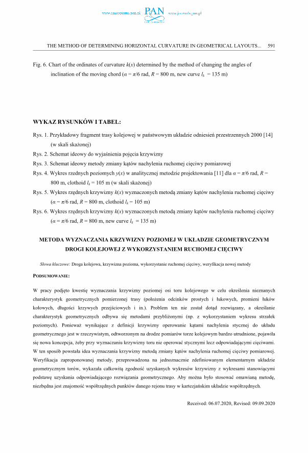
Fig. 6. Chart of the ordinates of curvature k(x) determined by the method of changing the angles of
inclination of the moving chord (α = π/6 rad, R = 800 m, new curve lk = 135 m)
WYKAZ RYSUNKÓW I TABEL:
Rys. 1. Przykładowy fragment trasy kolejowej w państwowym układzie odniesień przestrzennych 2000 [14]
(w skali skażonej)
Rys. 2. Schemat ideowy do wyjaśnienia pojęcia krzywizny
Rys. 3. Schemat ideowy metody zmiany kątów nachylenia ruchomej cięciwy pomiarowej
Rys. 4. Wykres rzednych poziomych y(x) w analitycznej metodzie projektowania [11] dla α = π/6 rad, R =
800 m, clothoid lk = 105 m (w skali skażonej)
Rys. 5. Wykres rzędnych krzywizny k(x) wyznaczonych metodą zmiany kątów nachylenia ruchomej cięciwy
(α = π/6 rad, R = 800 m, clothoid lk = 105 m)
Rys. 6. Wykres rzędnych krzywizny k(x) wyznaczonych metodą zmiany kątów nachylenia ruchomej cięciwy
(α = π/6 rad, R = 800 m, new curve lk = 135 m)
METODA WYZNACZANIA KRZYWIZNY POZIOMEJ W UKŁADZIE GEOMETRYCZNYM
DROGI KOLEJOWEJ Z WYKORZYSTANIEM RUCHOMEJ CIĘCIWY
Słowa kluczowe: Droga kolejowa, krzywizna pozioma, wykorzystanie ruchomej cięciwy, weryfikacja nowej metody
PODSUMOWANIE:
W pracy podjęto kwestię wyznaczania krzywizny poziomej osi toru kolejowego w celu określenia nieznanych
charakterystyk geometrycznych pomierzonej trasy (położenia odcinków prostych i łukowych, promieni łuków
kołowych, długości krzywych przejściowych i in.). Problem ten nie został dotąd rozwiązany, a określanie
charakterystyk geometrycznych odbywa się metodami przybliżonymi (np. z wykorzystaniem wykresu strzałek
poziomych). Ponieważ wynikające z definicji krzywizny operowanie kątami nachylenia stycznej do układu
geometrycznego jest w rzeczywistym, odtworzonym na drodze pomiarów torze kolejowym bardzo utrudnione, pojawiła
się nowa koncepcja, żeby przy wyznaczaniu krzywizny toru nie operować stycznymi lecz odpowiadającymi cięciwami.
W ten sposób powstała idea wyznaczania krzywizny metodą zmiany kątów nachylenia ruchomej cięciwy pomiarowej.
Weryfikacja zaproponowanej metody, przeprowadzona na jednoznacznie zdefiniowanym elementarnym układzie
geometrycznym torów, wykazała całkowitą zgodność uzyskanych wykresów krzywizny z wykresami stanowiącymi
podstawę uzyskania odpowiadającego rozwiązania geometrycznego. Aby można było stosować omawianą metodę,
niezbędna jest znajomość współrzędnych punktów danego rejonu trasy w kartezjańskim układzie współrzędnych.
Received: 06.07.2020, Revised: 09.09.2020
THE METHOD OF DETERMINING HORIZONTAL CURVATURE IN GEOMETRICAL LAYOUTS... 591