Embed Size (px)
Citation preview
Cent. Eur. J. Eng. • 2(3) • 2012 • 399-409DOI: 10.2478/s13531-012-0005-5
Central European Journal of Engineering
The method of assessment of the grinding wheelcutting ability in the plunge grinding
Research article
Krzysztof Nadolny∗
Department of Production Engineering, Faculty of Mechanical Engineering, Koszalin University of Technology,Racławicka 15-17, 75-620 Koszalin, Poland
Received 13 July 2011; accepted 31 January 2012
Abstract: This article presents the method of comparative assessment of the grinding wheel cutting ability in the plungegrinding kinematics. A new method has been developed to facilitate multicriterial assessment of the workingconditions of the abrasive grains and the bond bridges, as well as the wear mechanisms of the GWAS, which occurduring the grinding process, with simultaneous limitation of the workshop tests range. The work hereby describesthe methodology of assessment of the grinding wheel cutting ability in a short grinding test that lasts for 3 seconds,for example, with a specially shaped grinding wheel, in plunge grinding. The grinding wheel macrogeometrymodification applied in the developed method consists in forming a cone or a few zones of various diameters onits surface in the dressing cut. It presents an exemplary application of two variants of the method in the internalcylindrical plunge grinding, in 100Cr6 steel. Grinding wheels with microcrystalline corundum grains and ceramicbond underwent assessment. Analysis of the registered machining results showed greater efficacy of the methodof cutting using a grinding wheel with zones of various diameters. The method allows for comparative tests upondifferent grinding wheels, with various grinding parameters and different machined materials.
Keywords: Plunge grinding • Internal cylindrical grinding • Grinding wheel wear • Microcrystalline sintered corundum • Glass-crystalline bond© Versita sp. z o.o.
1. Introduction
Grinding is applied in modern automated production toobtain precision shaped, high-quality surfaces [1–7]. Thecourse, and results, of the grinding processes mostly de-pends upon the grinding wheel cutting ability, definedas the tool’s potential to remove the machined materialduring the grinding process. In this context it is crucialto select the right grinding wheel characteristics and tobe able to evaluate the components of its active surface
∗E-mail: [email protected]
working conditions (abrasive grains and bond). A numberof factors influence the conditions in the grinding wheelzone of contact (with the workpiece), such as: the grindingwheel characteristics, the grinding wheel type, processparameters, kinematics, the workpiece type and the con-sumption and method of application of the coolant, amongstothers [3–5, 8–11]. For this reason quick and many-sidedassessment of the grinding wheel cutting ability is crucialto optimize the tool’s working conditions in relation to theaspects of its wear and eventually to obtain satisfactoryand repeatable machining results.Abrasive grain-related methods have been hitherto used inassessment of phenomena that take place in the grinding
399

The method of assessment of the grinding wheel cutting ability in the plunge grinding
zone. They consist of analyzing the results of attemptsto cut with a single abrasive grain [12–15]. Such grain isoriented and mounted in a metal casing (usually throughsoldering), which is then used to make scratches on theworkpiece surface. Such methods are based chiefly on as-sessment of the removed material volume and the abrasivegrain mass loss, registration of the grinding power andanalyzes of the visual cutting marks, grain wear forms, chipshapes or the mechanism of fash creation. However, ap-plication of the methods of assessment, involving abrasivegrain machinability, cutting with a single-grain, are lim-ited as they do not take into consideration, the followingaspects, amongst others:
• specific kinematics of the grinding process variants;
• grinding dynamics in the given kinematics;
• influence of adjacent grains in the grinding wheel;
• influence of the bond on the grinding process andthe grain bonding force;
• influence of the pore volume on the ability of thecoolant to reach the grinding zone and on the abilityto gather and remove chips and grinding productsfrom the machining zone;
• randomness of the grain orientation in the grindingwheel;
• influence of smearings created on the grinding wheelactive surface (GWAS).
What can sometimes be found in subject literature are de-scriptions of cutting ability assessment methods, referringnot only to abrasive grains, but even the whole grindingwheel. However, in most cases, they require performinglong-term experimental tests [11, 16–18]. Methods thatallow quick grinding wheel assessment are usually limitedto one synthetic marker, or a few synthetic markers [19],which allow the evaluators to draw conclusions.In relation to the above details, a new method has beendeveloped [20] to facilitate multicriterial assessment of theworking conditions of the abrasive grains and the bondbridges, as well as the wear mechanisms of the GWAScomponents, which occur during the grinding process, withsimultaneous limitation of the workshop tests range. Suchmethod would be applicable mainly in comparative testsrealized to optimize the grinding wheel structure and thegrinding parameters.
2. Essence of the methodThe described method has been developed with the internalcylindrical plunge grinding process in mind but it can also
be successfully used in grinding of shafts or flat surfaces. Itconsists of a short grinding test that lasts for 3 seconds, forexample, with a specially shaped grinding wheel, in plungegrinding kinematics [20]. One of the crucial features of thismethod is omitting the finish grinding and sparking-outstages. The grinding wheel performs working movementwith the applied radial table feed speed vfr , after which itis immediately removed from the workpiece. This aims toobtain the most precise identification of the GWAS wearmechanisms, as well as material removal, chip forming,fash forming, ridging and other mechanisms.The grinding wheel macrogeometry modification applied inthe developed method consists in forming a cone or a fewzones of various diameters on its surface in the dressing cut.Fig. 1 presents the kinematic scheme of plunge grindingwith a conical grinding wheel (Fig. 1a) and a grindingwheel with zones of various diameters (Fig 1b), as wellas the geometry of two developed GWAS macrogeometrymodifications.In case of shaping the cone on the GWAS, its χ angleshould be selected with consideration of such geometricparameters as: grinding wheel height T , workpiece widthbw and machining allowance ae. It is advised to movethe grinding wheel ridge with greater diameter a certaindistance l in relation to the workpiece (Fig. 1a). Thisguarantees later observation of the grinding effects ofgrains placed on the greatest GWAS operational radius.When performing tests using a grinding wheel with zones ofvarious diameters, it should be prepared in such way so asto obtain even division of T height into particular workingzones (Fig. 1b). The developed method also assumes thatthe total machining allowance ae is divided evenly overthe subsequent grinding wheel zones.The result of such plunge grinding is the mapping of thegrinding wheel macrogeometry onto the workpiece, as ex-emplified by Fig. 2. Axis grinding wheel profiles measuredwith the optical profilometry method, with stylus profilome-ter registered profiles of surface roughness after grinding,were mapped onto it.The special shaping of the grinding wheel macrogeometrymakes particular zones of its active surface work withvarying times and workpiece volume removal rates. Asa consequence, in particular GWAS zones, the abrasivegrains and bond wear, leading to the phenomena of chipforming, or smearing of intergranular spaces, to occur withdiffering intensities and in various forms. In the case ofthe conical grinding wheel, these changes take place in acontinuous, non-gradual manner, resulting from changesto the grinding wheel diameter (Fig. 2a). In the caseof the stepped grinding wheel, the machining conditionsand results are similar in particular grinding wheel zones(Fig. 2b).
400

K. Nadolny
Figure 1. Kinematics of the method of comparative assessment of the grinding wheel cutting ability and grinding wheels,with special macrogeometry, used in it: a) conical grinding wheel; b) grinding wheel with zones of variousdiameters.
Figure 2. Measured axial profiles of the grinding wheel and the workpiece after plunge grinding: a) using conical grindingwheel; b) using grinding wheel with zones of various diameters.
A comparative assessment of the GWAS components cut-ting ability can be realized on basis of grinding parametersregistered during the process, such as: grinding powerand force, changes of the acoustic emission signal values,vibration and temperature. Further assessment of the grind-ing wheel cutting ability is carried-out after the variousmeasurements and analyzes of the GWAS, post-grinding,
were conducted. Thus, such analyzes, look at the resultsof the measurement of volumetric and profile wear of thegrinding wheel, the parameters of the geometrical structureof the surface (GSS) and microscopic image registrationand visual assessment of the degree, and forms, of abra-sive grain wear. The cutting ability assessment is alsorelated to the grinding results observed on the workpiece
401

The method of assessment of the grinding wheel cutting ability in the plunge grinding
by measuring the workpiece removal rate, parameters ofthe GSS, shape deviations, microhardness, strains in thesurface layer, detecting grinding defects such as burnsor microcracks, or registration of microscopic images andvisual assessment of the cutting marks.The developed method allows then for a vast analysis oftest results, which should, however, be usually limited tothe most useful parameters, as defined by the realized testaims.
3. Comparison of the assessmentpotential of methods utilising a co-nical grinding wheel and a grindingwheel with zones of various diametersTo compare the method’s possibilities using two GWASmacrogeometries, experimental tests using a tool madefrom microcrystalline sintered corundum and ceramic glass-crystalline bond [21–23] with the following technical mark-ing: 1-35×20×10-SG/F46G10VTO was used. The GWASmacrogeometry was shaped in the dressing process, using adiamond single-grain dresser whose mass was Qd = 1.25 kr.To shape the conical grinding wheel active surface whoseconical angle is χ = 0.21° it was necessary to use a specialdevice for precise conic chamfer shaping [24, 25]. Internalsurfaces of the bearing rings made from 100Cr6 steel withhardness 63±2 HRC were plunge grinded. The tests wereperformed on a working position which consisted of univer-sal grinder RUP-28P equipped with high-speed spindleEV-70/70-2WB, produced by Fischer (Switzerland).Test results obtained using the conical grinding wheel andthe grinding wheel with zones of various diameters arepresented below.
3.1. Results of experiments operated usingconical grinding wheel
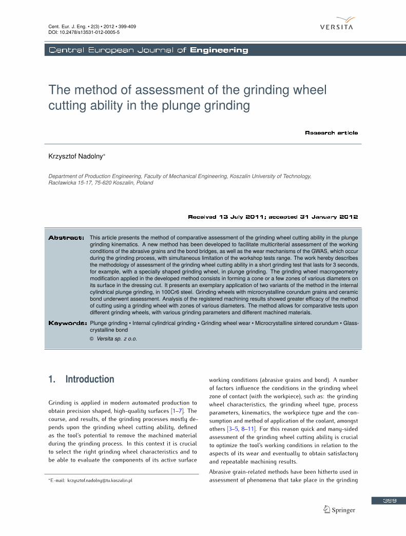
The first stage of assessment of the results of plunge grind-ing performed with the conical grinding wheel consisted inanalysis of its active surface condition. For this purposeSEM images were registered and the topography of thegrinding wheel after machining was measured. In this casea scanning electron microscope JSM5500LV, produced byJEOL Ltd. (Japan), and a measurement system TalysurfCLI 2000, produced by Taylor Hobson Ltd. (UK), wereused. Fig. 3 depicts, among others things, the microscopicimage which shows a 50× magnification of approximately2.5 mm of the GWAS perimeter over its whole breadth,comprised of a few dozen single images (Fig. 3b). Next,characteristic elements present on the GWAS in its subse-
quent fragments were observed in 200×, 500× and 1000×magnifications, which made analysis of the changes, result-ing from increasing allowance and grinding times, possible(Figs. 3c–e).The analysis of the registered GWAS microscopic imagesclearly shows that as the grinding time increases, the abra-sive grains’ wear is greater and greater, and the abrasivewear of the GWAS components dominates. In the GWASarea where the machining allowance is low, it is caused byinteraction between the grinding wheel components andthe workpiece. As the allowance and the grinding timeincrease, the abraded surface of the grain vertexes getslarger and larger (Fig. 3e). Microsmearings are present inthe GWAS area which operated the longest (for approxi-mately 3 seconds) and mapping of the workpiece surfaceshape on the active vertex of one of the grinding wheelscan be observed. This proves plasticization of the micro-crystalline sintered corundum grain vertexes occurs [11]created as a result of the abrasive wear caused by hightemperatures in the area of contact between the grindingwheel and the workpiece [5, 8]. Such temperature increaseresults from the fact that the described test was carriedout without the use of a coolant.On basis of the GWAS microscopic images the size andshape of the chips created in the grinding process can alsobe assessed. The image presented in Fig. 3 (detail 1) showsthat continuous and arc chips predominate, which resultsfrom the plastic properties of the ground steel. It can alsobe observed that the chip size increases along with themachining allowance. The presence of ball chips visiblein Fig. 3 (detail 2) also proves significant temperatureincrease in the microareas of the zone of contact betweenthe grinding wheel and the workpiece.Fig. 4 presents axonometric views of the conical grindingwheel active surface microtopography and the workpiecesurface with selected parameters (Sa, St, Sk, Sdr ) ofgeometrical surface structure, determined for three exem-plary zones. The GWAS topographies were registeredusing the measurement system Talysurf CLI 2000, pro-duced by Taylor Hobson Ltd. (UK). The stylus profilometerHommel-Tester T8000, produced by Hommelwerke GmbH(Germany) was used to measure the workpiece surfacemicrotopography.The calculated values of the arithmetical mean height Saof the GWAS (Fig. 4k) remain on a similar level to allthree measured grinding wheel areas and their dispersiondoes not exceed 15%. Kernel roughness depth Sk (Fig. 4l),whose values decrease in the subsequent grinding wheelareas, proves that dulling of the abrasive grains occurs overtime. Sk parameter values for zones II and III decreasedrespectively by 15 and 30% in comparison to the valuedetermined from the GWAS microtopography in zone I. Thesame direction of change was observed in the results of
402
K. Nadolny
Figure 3. SEM microphotographs of the active surface of the conical grinding wheel after internal cylindrical plunge grinding of 100Cr6 steel:a) overall view of the tool; b) mag. 50×; c) mag. 200×; d) mag. 500×; e) mag. 1000×.
403

The method of assessment of the grinding wheel cutting ability in the plunge grinding
Figure 4. Microtopographies and selected GSS parameters of the active surface of the conical grinding wheel and the workpiece: a) scheme of theprocess; b) measured microtopography of the GWAS; c) levelled microtopography of the GWAS; d–f) selected GSS parameters for thethree zones of the GWAS; g) measured microtopography of the workpiece surface; h–j) selected GSS parameters for the three zones ofthe workpiece surface; k–m) setting-up of values of the selected GSS parameters for the three areas of the GWAS; n–r) setting-up ofvalues of the selected GSS parameters for the three areas of the workpiece surface.
404

K. Nadolny
the developed interfacial area ratio Sdr (Fig. 4m), whosevalues decreased in total by 12.5%, when zones I and IIIare compared.The research methodology that has been used, character-ized by omitting the finish and sparking-out stages, madethe GSS parameters related to the workpiece surface(Figs. 4n–r) assume relatively high values. As a result,on the basis of the measured surface microtopographyafter grinding, conclusions can be drawn concerning thecourse of the cutting mechanism in the rough grindingconditions. A comparison of the workpiece surface rough-ness parameter values, with various allowances, showsthat as the machining allowance increases, the surfaceroughness, after machining, grows. In case of parametersSa, St and Sk, the increase was respectively 25, 22 and34%, if values calculated in areas I and III are compared.This results from the increasing, along with the grindingwheel diameter, cross-section of the cut layer accruingon a single abrasive grain. The determined Sdr parame-ter values remained at a similar level and the differencebetween them did not exceed 5%. This proves that themachined surface was developed in a similar manner inall three measured areas.The realized analyses of the condition of the GWAS andthe workpiece surface, after grinding, shows that with theassumed machining parameters, the grinding wheel cut-ting ability decreases along with the machining allowance.Despite the very short grinding time, which was 3 seconds,the abrasive grains located on the greatest grinding wheeldiameter suffered visible wear. This means that undertak-ing of grinding in such conditions causes a rapid loss ofthe grinding wheel cutting ability. Therefore, improvementof the tool working conditions is desired and should belooked for, e.g. through the application of coolant.
3.2. Results of experiments operated usinggrinding wheel with zones of various diameters
The test of the grinding wheel with zones of various diame-ters was conducted using a coolant, in the form of a watersolution with 5% of Castrol Syntilo RHS oil, introducedinto the machining zone, via the flooding method, with theflow rate Qc = 3.0 l/min.Fig. 5 presents SEM images recorded in three zones ofthe active surface of the examined grinding wheel.The analysis of the obtained images (Fig. 5) shows that asa result of cooling, the abrasion surfaces of the abrasivegrains were considerably less diminishing in comparisonwith the conical grinding wheel active surface images afterdry grinding (Fig. 3). This proves that the temperature inthe contact zone was decreased as a result of applicationof the coolant. However, this procedure did not prevent
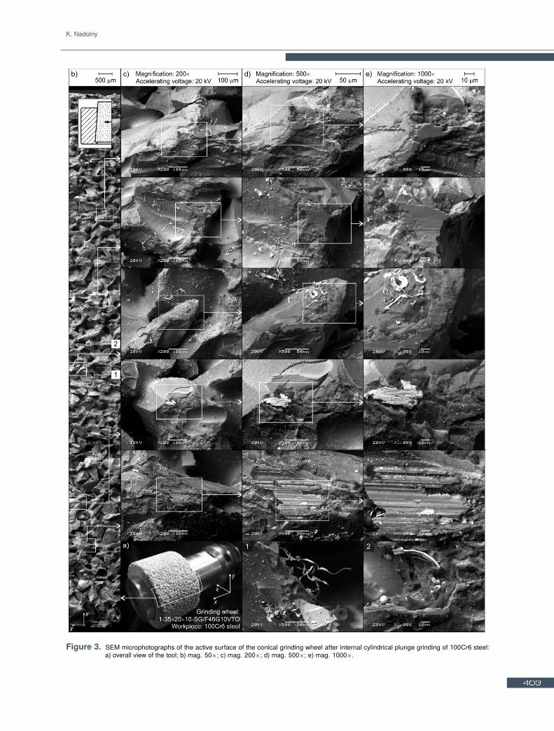
occurrence of microsmearings on the grain vertexes, espe-cially in the II and III GWAS zones (Fig. 5). No continuouschips were registered on the GWAS, only minor microchipsplaced around the active grain vertexes which took part inthe material removal process.Fig. 6 compares the axonometric views of the microtopogra-phy of the active surface of the grinding wheel with zonesof various diameters and the workpiece surface measuredin three zones. The calculated values of the chosen GSSparameters of the analyzed surfaces are presented in chartform in Figs. 6k–r.When GSS parameters of subsequent GWAS zones(Figs. 6k–m) are compared, it can be observed that theirvalues remain at a similar level for all three zones. Thegreatest differences in values were noted for parameter St(15%), while the dispersion of the Sa and Sdr parameterswas respectively 13 and 7%. The decreasing tendency ofSt and Sdr parameter values, along with the increasinggrinding time in subsequent tool zones, can prove thatinsignificant dulling of the active grain vertexes is takingplace.Comparison of the workpiece surface roughness param-eters, calculated for three subsequent machining zones(Figs. 6n–r), proves significant surface roughness increasein successive zones. The Sa, Sk and Sdr parameter valuesassumed values 50 to 63% greater in zone III, compared tozone I. As in zone I the machining allowance was 0.02 mmand in zone III it was 0.06 mm, thus it can be concluded thatthe machining allowance value influenced the geometricalstructure of the surface, shaped in the internal cylindricalplunge grinding process with the applied grinding wheel,in a decisive manner. It should also be emphasized thatthe roughness parameters of the surface machined with thegrinding wheel with zones of various diameters had two tothree times lower values in comparison to the roughnessparameters of the surface ground with the conical grindingwheel. This results from application of the coolant in thecase of grinding using the grinding wheel with zones ofvarious diameters.Shaping three zones with various diameters on the GWASallowed for assessment of the tool cutting ability simul-taneously after three different grinding times. With theassumed process parameters, the cutting ability of the ap-plied grinding wheel should be assessed as satisfactory, inrelation to all three assessed zones. What should also benoted are the occurring microsmearings on the active grainvertexes with grinding time t ≈ 2 s (zone II) and t ≈ 3 s(zone III). Their small size, however, does not threaten theprocess stability. Application of the coolant contributedto firm limitation of the mechanisms of abrasive wear ofthe active grain vertexes. This also influenced removalof the grinding products from the GWAS in a positivemanner.
405

The method of assessment of the grinding wheel cutting ability in the plunge grinding
Figure 5. SEM microphotographs of the active surface of the grinding wheel with zones of various diameters (zones I–III) after internal cylindricalplunge grinding of 100Cr6 steel: a) construction scheme of the tool; b) mag. 50×; c) mag. 200×; d) mag. 500×; e) mag. 1000×.
4. ConclusionsThe presented method of assessment, the cutting abilityof the grinding wheel in the plunge grinding process withgrinding wheels utilising a specially shaped active surfacemacrogeometry, was verified on basis of internal cylindri-cal grinding in steel 100Cr6. Analysis of the registeredmachining results showed greater efficacy of the methodof cutting using a grinding wheel with zones of variousdiameters. It allows for steering the grain strain in par-ticular grinding wheel zones through proper selection of
their diameters and operation time. It is also characterizedby constant grinding conditions in each zone, which en-ables the drawing of more reliable conclusions concerningthe machining conditions. Moreover, it does not requireapplication of special devices for precise shaping of smallangle cone on the GWAS. Shaping the zones with variousdiameters takes place using conventional dressing andconditioning methods for grinding wheels.The experimental tests performed confirmed the usefulnessof the presented method in assessing the mechanisms ofwear, of components of the grinding wheel active surface,
406
K. Nadolny
Figure 6. Microtopographies and selected GSS parameters of the active surface of the grinding wheel with zones of various diameters andthe workpiece: a) scheme of the process; b) measured microtopography of the GWAS; c) levelled microtopography of the GWAS;d–f) selected GSS parameters for the three zones of the GWAS; g) measured microtopography of the workpiece surface; h–j) selectedGSS parameters for the three zones of the workpiece surface; k–m) setting-up of values of the selected GSS parameters for the threeareas of the GWAS; n–r) setting-up of values of the selected GSS parameters for the three areas of the workpiece surface.
407
The method of assessment of the grinding wheel cutting ability in the plunge grinding
that take place during grinding, as well as the various phe-nomena that cause them. One of the greatest advantagesof this method is the fact that a multifaceted assessmentof the material removal conditions, resulting from changesto the grinding wheel components strain, is possible asa result of a short grinding test. The described methodalso enables comparative tests of grinding wheels with dif-ferent characteristics with diverse grinding parameters, orfor various workpieces. These features appear to be espe-cially useful in researching the grindability of hard-to-cutmaterials.
Nomenclature
GSS Geometrical Structure of SurfaceGWAS Grinding Wheel Active Surfaceae working engagement, mmbw workpiece breadth, mmds grinding wheel diameter, mmdw workpiece diameter, mml displacement of the grinding wheel relative to the work-
piece, mmns grinding wheel rotational frequency, rpmnw workpiece rotational frequency, rpmQc coolant flow rate, l/minQd mass of diamond dresser, krSa arithmetic mean height, µmSdr developed interfacial area ratio, %Sk kernel roughness depth (roughness depth of the core), µmSt total height of the surface, µmt grinding time, sT grinding wheel total height in axial direction, mmUa accelerating voltage, kVvfr radial table feed speed, mm/svs grinding wheel peripheral speed, m/svw workpiece peripheral speed, m/sVw material removal, mm3
χ angle of conic chamfer, °
AcknowledgmentsPart of this work was supported by the Polish Ministryof Science and Higher Education under Grant No. N503214837. The Author would like to thank the employeesof Koszalin University of Technology for their help andsupport in selected steps of the experimental investiga-tions: Mrs. Daniela Herman, DSc, PhD, from the Divisionof Fundamentals of Material Science of the Institute ofMechatronics, Nanotechnology and Vacuum Technique, forpreparing the grinding wheels for tests, Mr. Andrzej Nowi-cki from the Laboratory Team I for help in grinding tests,Mr. Adam Szpakowicz, MSc, BSc, from UnconventionalHydroJetting Technology Center, for the optical measure-ments of the surface microtopography of tested grinding
wheels, Mr. Krzysztof Maciejewski from the Laboratory ofMetrology And Measurement Systems for the stylus mea-surements of the surface microtopography of workpieces,as well as Mr. Ryszard Gritzman from the Central Labora-tory of the Institute of Mechatronics, Nanotechnology andVacuum Technique, for acquisition of SEM micrographs.
References
[1] Webster J., Tricard M., Innovations in abrasive productsfor precision grinding, CIRP ANN, 2004, 2, 597–617
[2] Malkin S., Guo C., Grinding Technology: The WayThings Can Work: Theory and Applications of Ma-chining with Abrasives, Industrial Press, New York,2008
[3] Klocke F., Manufacturing Processes 2: Grinding, Hon-ing, Lapping, Springler-Verlag, Berlin, 2009
[4] Rowe W.B., Principles of Modern Grinding TechnologyWilliam Andrew, Burlington, 2009
[5] Jackson M.J., Davim J.P., Machining with Abrasives,Springer, New York, 2010
[6] Słowiński B., Nadolny K., Effective manufacturingmethod for automated inside diameter grinding, J. Adv.Mech. Des. Sys. & Manuf., 2007, 4, 472–480
[7] Nadolny K., Plichta J., Herman D., Słowiński B.,Single-Pass Grinding – An Effective ManufacturingMethod for Finishing, In: Proceedings of 19th Interna-tional Conference on Systems Engineering – ICSENG2008, (August 19–21, Las Vegas USA), University ofNevada, 2008, 236–241
[8] Marinescu I. D., Rowe W. B., Dimitrov B., Inasaki I.,Tribology of abrasive machining processes, WilliamAndrew, Norwich, 2004
[9] Xu X., Yu Y., Huang H., Mechanisms of abrasive wearin the grinding of Titanium (TC4) and Nickel (K417)alloys, WEAR, 2003, 255, 1421–1426
[10] Jackson M.J., Microscale wear of vitrified abrasivematerials, J. Mater. Sci., 2004, 39, 2131–2143
[11] Mayer J., Engelhorn R., Bot R., Weirich T., HerwartzC., Klocke F., Wear characteristics of second-phase-reinforced sol-gel corundum abrasives, Acta Mater.,2006, 54, 3605–3615
[12] Wamecke G., Rosenberger U., Milberg J., Basics ofProcess Parameter Selection in Grinding of AdvancedCeramics, CIRP ANN, 1995, 44, 283–286
[13] Qu W., Wang K., Miller M.H., Huang Y., Chandra A.,Using vibration-assisted grinding to reduce subsurfacedamage. PREC ENG, 2000, 24, 329–337
[14] Brinksmeler E., Glwerzew A., Chip Formation Mecha-nisms in Grinding at Low Speeds, CIRP ANN, 2003,52, 253–258
408

K. Nadolny
[15] Hamdi H., Dursapt M., Zahouani H., Characterizationof abrasive grain’s behavior and wear mechanisms.WEAR, 2003, 254, 1294–1298
[16] Ichida Y., Mechanical properties and grinding perfor-mance of ultrafine-crystalline cBN abrasive grains,Diamond Relat. Mater., 2008, 17, 1791–1795
[17] Xu L-M, Xu K-Z, Chai Y-D, Identification of grindingwheel wear signature by a wavelet packet decomposi-tion method, J. Shanghai Jiaotong Univ. (SCI), 2010,15, 323–328
[18] Ding W.F., Xu J.H., Chen Z.Z., Su H.H, Fu Y.C., Grainwear of brazed polycrystalline CBN abrasive toolsduring constant-force grinding Ti-6Al-4V alloy, Int.J. Adv. Manuf. Tech., 2011, 52, 969–976
[19] Gołąbczak A., Koziarski T., Assessment method ofcutting ability of CBN grinding wheels, Int J Of MachTools Manuf, 2005, 45, 1256-1260
[20] Nadolny K., Plichta J., Procedure of examination ofthe grinding wheel’s cutting ability, Polish PatentApplication No. 395409, 2011
[21] Herman D., Plichta J., Karpiński T., Effect of glass-crystalline and amorphous binder application to abra-sive tools made of microcrystalline alumina grainstype SG, WEAR, 1997, 209, 213–218
[22] Herman D., Glass and glass-ceramic binder obtainedfrom waste material for binding alundum abrasivegrains into grinding wheels, CERAM INT, 1998, 24,515–520
[23] Herman D., Markul J., Influence of microstructuresof binder and abrasive grain on selected operationalproperties of ceramic grinding wheels made of alumina.Int. J. Mach. Tools Manuf., 2004, 44, 511–522
[24] Nadolny K., Device for shaping of conic chamfer ongrinding wheels surface for small angular values, Pol-ish Patent Application No. 388765, 2009
[25] Nadolny K., Kapłonek W., Design of a Device forPrecision Shaping of Grinding Wheel Macro- and Mi-crogeometry, J. Cent. South Univ. T, 2012, 19, 135–143
409