Embed Size (px)
Citation preview

5/22/2012
Page 1
IN THIS WEBINAR:
• Manipulate and Idealize Geometry
• Interactively Create and Manipulate
Mesh
• Check and Edit Mesh Quality
The Meshing Toolbox10 Tools to Quickly Create and Refine
Accurate Finite Element Models
Russ Hilley
Senior Aerospace Stress Engineer
Structural Design and Analysis
PRESENTED BY:

5/22/2012
Page 2STRUCTURES.AERO
Structural Design and Analysis (Structures.Aero)
Structural Analysis
• Team of stress engineers that help our clients
design lightweight and load efficient structures.
• We service aerospace companies and other
industries that require high level analysis.
• Specialty in composites and lightweight
structures
• Tools used include hand analysis, HyperSizer,
Femap, NX Nastran, Fibersim, NX, Solid Edge,
Simcenter 3D, LS Dyna, and LMS.
Software Sales and Support
• Value added reseller providing software, training,
and support for products we use on a daily
basis.
• Support Femap, NX Nastran, Simcenter 3D,
Fibersim, Solid Edge, and HyperSizer.

5/22/2012
Page 3STRUCTURES.AERO
Meshing Toolbox Topics
• What is it?– The meshing toolbox is a collection of tools which eases the geometry preparation, meshing,
and mesh refinement tasks.
• What does it do?– Locates features and mesh which can be improved.
– Prepares geometry by suppressing/removing features or adding/editing features to aid meshing.
– Mesh geometry and interactively refine meshes.
– Locate mesh for editing.
– Allows viewing of mesh quality.
• Help for the Meshing Toolbox– Section 7.2.2 of the FEMAP Commands Reference covers all of the Meshing Toolbox
Commands.
– Commands.pdf is found in the following folder.• C:\Program Files\Siemens\FEMAPv1141\pdf
3

5/22/2012
Page 4STRUCTURES.AERO
Inside the Meshing Toolbox
1. Toolbox Visibility –
Turn on or off individual tools as needed
2. Toggle Entity Locator –
Entity Locator isn’t on by default
3. Toggle Surface mesh quality – Show quality
attributes of the mesh.
4. Remesh Control – Mesh can be recreated
automatically with each change or changes
can be tracked to be implemented later.
5. Select or Select Dialog – Selects the
appropriate entity based on the tool in use.
4
1 2 3 4 5

5/22/2012
Page 5STRUCTURES.AERO
Entity Locator
• Common uses of the Entity Locator:
– Locate bad geometry: Curves or Surfaces which may not produce good mesh
– Locate bad mesh: Based on common quality attributes or edge length
– View Free Edges in geometry and mesh
5

5/22/2012
Page 6STRUCTURES.AERO
Quality Display
• Shows a 2 level plot of the Jacobian by default.
• Used in conjunction with the Surface Mesh
Quality tool to view other quality attributes as
well.
6

5/22/2012
Page 7STRUCTURES.AERO
Remesh Options
• Disable Remesh: Automatic remeshing does not occur as changes are being made.
The geometry will need to be manually remeshed when the remesh option is set to
Disable Remesh.
• Auto Remesh: Remeshes the geometry as changes are made
• Track Remesh Changes: The toolbox tracks changes made to the mesh or geometry
and allows all changes to be implemented at once.
• Remesh Entities: Remeshes the geometry and implements any tracked changes.
7

5/22/2012
Page 8STRUCTURES.AERO
Select
• Select: Allows entities to be selected one at a time or by using the Shift / Ctrl-
LMB and the Ctrl-Shift-LMB modifiers for a box, circle, or polygon pick.
– Entity type to be selected will change depending on the tool in use.
• Select Dialog: allows for the use of the FEMAP standard selection dialog box
along with the available methods and pick options for the entity type being
selected.
8

5/22/2012
Page 9STRUCTURES.AERO
Feature Suppression Tool
• As the name implies, the Feature Suppression
tool only suppresses the geometry and instructs
the mesher to ignore that feature.
• No permanent changes are made to the
underlying geometry.
• Features can be toggled easily from suppressed
to unsuppressed as individual features, all
features in a selected solid, or all features in the
current model.
• Suppressed features change colors to indicate
the feature is ignored by the mesher.
9
5/22/2012
Page 10STRUCTURES.AERO
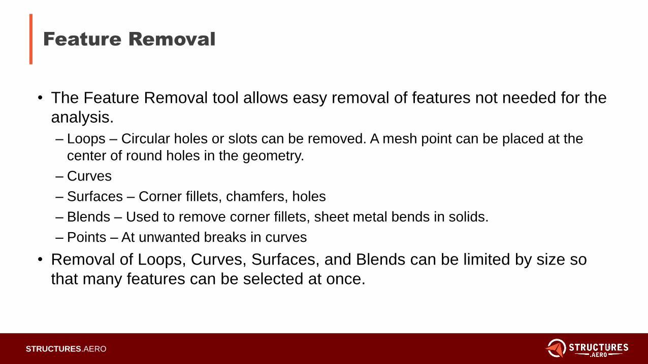
Feature Removal
• The Feature Removal tool allows easy removal of features not needed for the
analysis.
– Loops – Circular holes or slots can be removed. A mesh point can be placed at the
center of round holes in the geometry.
– Curves
– Surfaces – Corner fillets, chamfers, holes
– Blends – Used to remove corner fillets, sheet metal bends in solids.
– Points – At unwanted breaks in curves
• Removal of Loops, Curves, Surfaces, and Blends can be limited by size so
that many features can be selected at once.
10

5/22/2012
Page 11STRUCTURES.AERO
Feature Removal
• Loops removed and mesh point left at the hole centers. Leaving a mesh point
forces the mesher to place a node at that location.
– Size was limited so that the rectangular opening was ignored in the loop selection.
11

5/22/2012
Page 12STRUCTURES.AERO
Feature Removal
• Surface Removal
– Selected using the dialog select and add connected fillets.
12

5/22/2012
Page 13STRUCTURES.AERO
Feature Removal
• Blends – Works well for parts with sheet metal bends
13

5/22/2012
Page 14STRUCTURES.AERO
Feature Editing
• The Feature Editing tool is commonly used to make basic changes to
geometry.
– Move / rotate surfaces
– Resize holes
– Edit or Offset surfaces
• Saves time for simple changes. Remeshing is done interactively as the
geometry is changed.
14

5/22/2012
Page 15STRUCTURES.AERO
Feature Editing – Resize Hole
• Resizing Holes
– Enter a new hole diameter and use the select or dialog select to select the edges of
the hole.
15

5/22/2012
Page 16STRUCTURES.AERO
Feature Editing
• Feature Edges – Translate Surfaces
– Used mostly with internal features such as holes or slots.
– Meshing is updated interactively.
16

5/22/2012
Page 17STRUCTURES.AERO
Feature Editing
• Also works to translate features which aren’t holes or slots on sheet bodies
created with the midsurface commands.
17

5/22/2012
Page 18STRUCTURES.AERO
Geometry Editing
• The Geometry Editing tool allows the user to divide surfaces efficiently to
create regions more suitable for mapped meshing.
• Meshed surfaces can also be edited. The mesh will be interactively updated
based on the Remesh control setting.
18

5/22/2012
Page 19STRUCTURES.AERO
Geometry Editing
• Pads and Washer regions allow for mapped meshing
regions around holes.
– Mapped meshing options are automatically set.
19

5/22/2012
Page 20STRUCTURES.AERO
Geometry Editing
• Washer and Pad combinations can also be created.
20

5/22/2012
Page 21STRUCTURES.AERO
Geometry Editing
• Point to Point, Point to Edge, and Edge to Edge options are used
to add curves to the surface which will aid in mapped meshes.
21

5/22/2012
Page 22STRUCTURES.AERO
Geometry Editing
• Extend allows the user to extend one surface.
– To intersect another surface or solid
– To a location or distance
22

5/22/2012
Page 23STRUCTURES.AERO
Geometry Editing
• Project / Move Point allows the editing of surface corner locations.
– Select the desired location and then the point.
23

5/22/2012
Page 24STRUCTURES.AERO
Meshing Toolbox – Geometry Editing
• Project Curve – Splits surfaces using a curve in much the same way the
Geometry – Curve From Surface commands.
24

5/22/2012
Page 25STRUCTURES.AERO
Combined / Composite Curves
• Forces the mesher to treat
a combined set of shorter
curves as if meshing a
single curve.
– Curves change color to show
a composite curve
– Creates a more uniform
mapped mesh.
25

5/22/2012
Page 26STRUCTURES.AERO
Combined / Boundary Surfaces
• The Combined / Boundary Surfaces tool works much the same as the
Composite Curves tool but combines 2 or more surfaces to create a
composite surface.
– The mesher is forced to mesh the composite surface.
– As with combined curves, surfaces change color to indicate a composite surface.
26

5/22/2012
Page 27STRUCTURES.AERO
Mesh Surface Tool
• The Mesh Surface tool contains all the functionality of the
Mesh – Geometry – Surface command.
– Attributes can be loaded from another surface
– Property Setting
– Sizing Options
– Element size and Shape
– Mapped or Free Mesh
– Advanced Options: Post mesh cleanup, smoothing…
27

5/22/2012
Page 28STRUCTURES.AERO
Mesh Surface Tool
• Property – Use Meshing Attributes
– Allows the use of predefined meshing attributes set either using the Mesh – Mesh Control
– Attributes on Surface command or the Midsurface – Assign Mesh Attributes command.
• Property – The property can be defined on the fly using the browse button or
select a predefined property card created using the Model – Property
command.
28

5/22/2012
Page 29STRUCTURES.AERO
Mesh Surface Tool
• Four Mesh Sizing options available.
29

5/22/2012
Page 30STRUCTURES.AERO
Mesh Surface Tool
• Mesh Sizing Options – Off
– Setting used to change Element Shape, Meshing Method or Advanced Options without
changing the element size on any surfaces.
30

5/22/2012
Page 31STRUCTURES.AERO
Mesh Surface Tool
• Mesh Sizing Options – Size All, Connect (Most common and default)
– Resizes all curves of the selected surface the new mesh size, then meshes/remeshes the
surfaces and updates the Mesh Size on all shared curves of connected surfaces. The
mesh will be connected through the transitions.
31

5/22/2012
Page 32STRUCTURES.AERO
Mesh Surface Tool
• Mesh Sizing Option – Size All, Disconnect
– Resizes the curves of the selected surface with the new mesh size and remeshes the
surface. No attempt is made to connect surfaces which share curves.
32

5/22/2012
Page 33STRUCTURES.AERO
Mesh Surface Tool
• Mesh Sizing Options – Size, Internal / Free Edges.
– Resizes the "internal curves” or “free edges” of the selected surfaces. All curves “shared”
by selected surfaces and non-selected surfaces will NOT be resized.
33

5/22/2012
Page 34STRUCTURES.AERO
Mesh Surface Tool
• Element Shape
– Linear 3 Node Triangles
– Parabolic 6 Node Triangles
– Linear 4 Node Quad
– Parabolic 8 Node Quad
34

5/22/2012
Page 35STRUCTURES.AERO
Mesh Surface Tool
• Free Mesh
– Max Quads – FEMAP will attempt to create an all quad free mesh minimizing the use
of triangle elements.
– Quad / Tri Layers – When set, this option will create the desired number of quad
element layers around internal boundaries such as holes or slots
– Min Elements Between Boundaries – The mesher will place the set number of
elements, up to 3 layers, between boundaries
– Show Free Edges – When enabled, this options highlights nodes on free edges.
35

5/22/2012
Page 36STRUCTURES.AERO
Mesh Surface Tool
• Mapped Mesh – Attempts to create a mapped quad mesh similar to using the
Mesh – Mesh Control – Approach on Surface command.
– Auto Approach – When enabled, FEMAP will determine the best approach for a given
selected surface. Disable this options to specify an approach using the same options
found in the Mesh Control – Approach on Surface command.
36

5/22/2012
Page 37STRUCTURES.AERO
Mesh Surface Tool
• Mapped Mesh
– Auto Mapped Approach enabled.
– Auto Mapped Approach disabled to manually select a desired approach.
37

5/22/2012
Page 38STRUCTURES.AERO
Mesh Sizing Tool
• The mesh sizing tool is used to set mesh size and node spacing on curves.
– Mesh interactively changes when mesh size is changed on curves if Auto Remesh is
enabled.
– Works best with plate meshes and tetrahedral meshes.
– Options are available for matching nodes or curves. This is similar to the Mesh – Mesh
Control – Custom size on curve command.
– Spacing options are available to bias the mesh toward the ends or middle of curves.
38

5/22/2012
Page 39STRUCTURES.AERO
Mesh Sizing Tool
• Size Curves
– Increase and Decrease will change the number of nodes on a curve by a set number of
elements or by a factor.
– Set to a desired number of elements on curves.
– Sizing changes can be propagated by mapped approaches.
39

5/22/2012
Page 40STRUCTURES.AERO
Mesh Sizing Tool
• Match Curves or Nodes
– Allows for the selection of one or more curves or nodes which will be matched on the
selected curve.
• Select the curve or nodes to match
• Select the curve to have the matching mesh
40

5/22/2012
Page 41STRUCTURES.AERO
Mesh Sizing Tool
• Spacing Options – Similar to the node spacing options in the Mesh – Mesh
Control – Size on Curve command.
– The spacing options are used to bias the mesh to one end, middle, or a selected bias
location of the selected curves.
41

5/22/2012
Page 42STRUCTURES.AERO
Mesh Locate
• The Mesh Locate tool allows moving one or more nodes dynamically without
changing the number of elements.
– Move nodes to represent a connection location
– Move nodes to improve mesh quality. The mesh locate tool can be used in conjunction
with the Surface Mesh Quality tool.
– Mesh to edit can be selected based on geometry or as a standalone mesh.
– If the Constrain to Curve/Surf is enabled, nodes will remain attached to the geometry
and cannot be dragged out of plane or off the edge of the surface. This is option is on
by default and is preferred.
42

5/22/2012
Page 43STRUCTURES.AERO
Mesh Locate
• Mesh Quality shown with original node locations and then moved to improve
quality.
– The changes can be saved or discarded in the Mesh Locate tool.
43

5/22/2012
Page 44STRUCTURES.AERO
Surface Mesh Quality
• The Surface Mesh Quality tool allows you to view mesh quality as a contour /
criteria plot.
44

5/22/2012
Page 45STRUCTURES.AERO
Surface Mesh Quality
• Quality Source – Femap or Nastran
– The checks available in the pull down for each are the same checks and
default values used in the Tools – Check – Element Quality command.
45

5/22/2012
Page 46STRUCTURES.AERO
Surface Mesh Quality
• The default is to show a contour / criteria of the Jacobian with a max value of
0.6.
– The value can be changed if needed.
– The contour / criteria can show 2 or 4 levels.
46

5/22/2012
Page 47STRUCTURES.AERO
Surface Mesh Quality
• For any quality attribute chosen, the Surface Mesh Quality tool will show the
minimum and maximum values.
47

5/22/2012
Page 48STRUCTURES.AERO
For questions on the material covered
today, please contact Russ Hilley.
For questions about pricing, or to see a
demo, please contact Marty Sivic.
Questions?
Marty SivicDirector of Sales
724-382-5290
Russ HilleySenior Aerospace Stress Engineer
703-657-0919
![Wing meshing in SALOME - · PDF fileTUT1101R0 Wing meshing in SALOME Table of Contents 1 Log of revisions ... the SALOME meshing software [ref 2]. The mesh is made of both quadrangle](https://img.pdfslide.us/doc/110x75/5a9e9ecd7f8b9a67178b9cab/wing-meshing-in-salome-wing-meshing-in-salome-table-of-contents-1-log-of-revisions.jpg)