Embed Size (px)
Citation preview

water
Article
The Mechanical Properties of High StrengthReinforced Cured-in-Place Pipe (CIPP) LinerComposites for Urban WaterInfrastructure Rehabilitation
Hyun Wook Ji 1 ID , Sung Soo Yoo 1,*, Jonghoon Kim 2 and Dan Daehyun Koo 3 ID
1 Environmental and Plant Engineering Research Institute, Korea Institute of Civil Engineering and BuildingTechnology, 283, Goyangdae-Ro, Ilsanseo-Gu, Goyang, Gyeonggi-Do 10223, Korea; [email protected]
2 College of Engineering, Architecture, and Technology, Oklahoma State University, 509 Engineering North,Stillwater, OK 74078, USA; [email protected]
3 Department of Engineering Technology, Indiana University-Purdue University Indianapolis (IUPUI),799 W. Michigan St. ET 314J, Indianapolis, IN 46202, USA; [email protected]
* Correspondence: [email protected]; Tel.: +82-10-8863-1569
Received: 30 May 2018; Accepted: 23 July 2018; Published: 26 July 2018�����������������
Abstract: Most urban areas in the world have water infrastructure systems, including the buriedsewer and water pipelines, which are assessed as in need of extensive rehabilitation. Deterioration bymany other factors affects structural integrity. Trenchless technologies such as Cured-in-Place Pipe(CIPP) are now applied in numerous projects while minimizing disturbance in an urban environment.The main purpose of this study is to develop a high strength CIPP material using various compositematerials (e.g., glass fiber, carbon fiber, polyester felt, unsaturated polyester resin, and others).Composite samples were made of the materials and tested using three-point bend apparatus to findmechanical properties, which include the flexural modulus, strength, and deflection. A compositecombination with glass fibers with thin felt layers shows the best results in mechanical properties.Flexural modulus is a key factor for CIPP liner thickness design. Glass fiber composite yields betweenfour and nine times higher values than the minimum value specified in the American Society forTesting and Materials (ASTM) F1216. This study provides a fundamental baseline for high strengthCIPP liners that are capable of using conventional curing technologies.
Keywords: Cured-in-Place Pipe (CIPP); pipe rehabilitation; composite material
1. Introduction
Sewer and water pipelines are key infrastructure systems in the urban environment, but thesystems keep failing due to the structural degradation. Aging is the most significant reason for thestructural deterioration of the buried infrastructure systems. Demand for capital improvement projectssuch as rehabilitation continuously increases as those systems keep failing. However, there is a hugegap in between the increasing rehabilitation demand and actual resources available. The structuralassessment grade for sewer and water conveyance systems are D grade in the 2017 American societyof civil engineers (ASCE) infrastructure report card [1]. There are over 800,000 miles of public sewersand 500,000 miles of private lateral sewers in the United States [1]. Trenchless technology is a group ofengineering and construction methods, which minimize open-cut excavation. The primary benefit ofthe trenchless technology is to significantly reduce surface disruption during the construction phase [2].Since its invention from the early 1970s, Cured-in-Place Pipe (CIPP) has been an effective rehabilitationtechnology, especially for sewers. However, research and development have been left behind, and the
Water 2018, 10, 983; doi:10.3390/w10080983 www.mdpi.com/journal/water

Water 2018, 10, 983 2 of 12
majority still uses traditional polyester felts. The main purpose of this study is to find high strengthcomposite materials that are suitable for further development in CIPP application.
CIPP is a hollow cylinder containing a non-woven or woven fabric material, such as a felt layer,which is impregnated by a cured thermosetting resin. This new CIPP liner is formed within anexisting pipe taking the geometry of and fits tightly to the existing pipe [3]. Resin is impregnatedthrough layers of CIPP liners in a factory, then the liners are installed by using inversion or pulledin place technique at the construction site. The most common thermosetting resins used for sewerapplication is unsaturated polyester, and vinyl ester resin is especially used for the highly corrosivecondition in need of chemical resistance liner. Glass fiber reinforced liners have developed forultra-violet (UV) light curing application. The glass fiber reinforced liners are mainly installed by thepull-in installation method, and this application requires a calibration tube for the curing purpose.The glass reinforced CIPP has several advantages over the conventional felt based CIPP liner. The mostsignificant advantage of the glass reinforced CIPP is its high strength. However, UV curing and use ofa calibration tube make it challenging to improve construction productivity and cost competitiveness.
Although conventional CIPP is the most widely accepted and proven method for sewerrehabilitation, the lack of knowledge regarding the engineering performance of emerging new CIPPtechnology indicates that further research needs to address. CIPP for a water pipe rehabilitationapplication is also available in the industry. However, the pressurized water pipe application hasgained less popularity mainly because of two reasons. Firstly, 100 percent solid epoxy resin, which isonly approved by national sanitation foundation (NSF) 61 for the potable water CIPP, is much morecostly than polyester resin. Secondly, the water pipe system has limited access for work and it is buriedshallower than the sewer. In this case, the benefit of trenchless rehabiliation for the pressurized waterpipe is less significant than the sewer. Flexural Strength and modulus are critical mechanical propertiesto determine the wall thickness of the CIPP liner. The wall thickness increases as loads and diameterof the existing pipe increases. Development of high flexural strength and modulus CIPP liner materialis necessary to maximize flow capacity of the existing pipe, improve construction productivity on site,and reduce CIPP liner manufacturing cost. This study was seeking to identify composite materialsattaining higher flexural strength and modulus with five percent maximum deformation. The mainobjectives of this study are: (1) to verify critical mechanical properties acquired from various CIPPliner composite sample tests and (2) to find the most effective composite layout.
2. Previous Studies
Many previous CIPP studies focused on case studies and retrospective performance assessment.Allouch et al. [4] conducted a retrospective evaluation of CIPP used in municipal gravity sewers. Theyretrieved testing samples from two cities installed over 20 years ago. They compared sample testingresults with the original testing results at the time of the CIPP liner completion. Average flexuralstrength and modulus values show above a minimum threshold in American Society for Testingand Materials (ASTM) F1216 [3], but significant variation was verified between original test resultsand retrospective test results. It may occur during sample creation and tests. In their summary, theperformance of the CIPP liners over 20 years indicates that life expectancy for the CIPP liners meets ormay exceed the 50 years which has been taken as the nominal life expectancy in design.
The standard design guidelines are adopted for CIPP liner design calculation. A few examples ofthe widely accepted standard design guidelines are ASTM F1216 [3] in the United States, SewerageRehabilitation Manual (WRc SRM) [5] Type II in the United Kingdom, and ATV 127 [6] in Germany.The design methods are slightly different depending on the shape of the existing pipe, pressure status,and existing pipe condition. The primary function of those design methods is to determine the linerwall thickness, which provides the necessary structural capacity to resist the external and internal loads.Since the loads are relatively constant on the CIPP liners throughout the design life, the long-termmechanical properties are critical design factors to design the CIPP liner. The industry practice forthe design life is typically 50 years in the long-term application. Therefore, CIPP design methods use

Water 2018, 10, 983 3 of 12
long-term mechanical properties to calculate the thickness of the CIPP liner. Three-point load bendingtest is used for flexural strength and modulus of the CIPP liner sample. ASTM D790 [7] is a standardthree-point load bend test.
CIPP mechanical properties are investigated to find long-term and short-term tensile strength,flexural strength, and flexural modulus. Riahi [8] studied long-term and short-term properties toensure that the design requirements were met. Riahi’s test results revealed that the Creep RetentionFactor (CRF) varies by resin types and manufacturers. The ASTM F1216 [3] adopts a long-term flexuralmodulus for calculation of CIPP liner thickness design. Therefore, CRF value controls the design ofthe CIPP liner. A CRF of 0.5 (50% retention of short-term flexural modulus) is typically adopted as anindustry standard practice [9]. CRF 0.5 is still used for non-reinforced CIPP using standard polyesterresin system. On the contrary, a reinforced CIPP structure retains higher CRF values. North AmericanSociety for Trenchless Technology (NASTT) [10] present typical CIPP mechanical property values forgravity pipelines in good practice guidelines. They suggest CRF up to 80 percent for highly reinforcedCIPP. A long-term creep test only confirms CRF. Nassar and Yousef [11] experimented and analyzeda long-term buckling behavior of a pipe under external hydrostatic pressure for at least 50 years.Their work shows that the current regression-based prediction for the long-term failure analysis isconservative and actual CIPP behavior is less likely failed with over 80 percent survival probability.
Glass fiber has been used as a lightweight reinforcement material for many composites such aspolymer and concrete structures. Matthews [12] describe a 2400 mm diameter sewer rehabilitationusing a partial glass fiber reinforced CIPP. A typical UV curing system is limited to 1200 mm indiameter. The described CIPP technology used as a hybrid to overcome the size limit and used ahot water curing system. Glass fiber reinforced polymer (GRP) is used instead of needle felt layerand increases flexural strength and modulus. Akinci et al. [13] conducted tests to compare GRP CIPP,and a conventional needle felt CIPP liner. The test results revealed that flexural modulus of the GRPyielded over 10 GPa. The test was limited by only comparing 100 percent GRP to 100 percent needlefelt liner. Dong et al. [14] tested conventional Fiber Reinforced Polymer (FRP) composites using E glassand carbon fiber with epoxy resin. The composite was not intended for CIPP application. Epoxy ispredominantly used for potable water rehabilitation. Installation and curing process for the epoxyresin is significantly different than polyester resin. Review of the previous studies and literaturerevealed that the insufficient level of knowledge would be available for reinforced CIPP compositeliner mechanical property.
3. Materials and Methods
Flexural mechanical properties can be determined by three-point bend test, in which a loadingnose deflects a specimen on a set span and rate until the specimen fractures. While loading thespecimen, the underside is subjected to tensile stress, and the upper side is subjected to compressivestress. Any excessive stress of tensile, compressive or shear stress will cause fracture of the specimen.The test measures deflection of the sample and magnitude of loading to the sample. The three-pointbending test is not able to identify a specific reason for the fracture.
Six composite groups were categorized as shown in Table 1. It shows that materials used forcomposites and their thickness with unit weight. Details of composite layer are described in Table 2,in Composition Layer Order column. Depending on the number of composite layers, materials,and thickness, total 21 group compositions were categorized as shown in Table 2. Multiple testingspecimens were cut from the 21 group compositions.
ASTM F1216 [3] provides the minimum CIPP flexural modulus and strength for partially and fullydeteriorated existing pipe conditions. The CIPP industry uses ASTM F1216 [3] as the prime referencefor both design and manufacturing of the CIPP liner. Minimum flexural modulus and strength arerespectively 1724 Mpa (1.724 Gpa) and 31 MPa. Before polymerization (curing) of resin, the resin isliquid state to facilitate being impregnated in the felt liners. The impregnated liners shall be flexibleenough to fit tight within the existing pipe. Polymerization hardens the resin and finally gains designed

Water 2018, 10, 983 4 of 12
mechanical properties. The flexural strength of a conventional needle felt mostly based CIPP dependson the cured resin strength. Group No. 1 is made of high strength 100 percent unsaturated polyesterresin, which has approximately two times of ASTM minimum flexural modulus. This polyester resinplate sample is used as a baseline for the further comparison to the test results of others.
Table 1. Sample Composition.
Group Number Composition Criteria Materials Thickness Unit Weight
1 Polyester Resin Unsaturated Polyester with styrenemonomer for CIPP (UP) N/A 1.13 g/cm3
2Glass Fiber andPolyester Resin
Thin Roving Cross GlassFiber Mat (TG) 0.5 mm 0.9 g/cm3
Roving Cross Glass Fiber andChopped Strand Mat (G) 1.0 mm 0.96 g/cm3
Unsaturated Polyester with styrenemonomer for CIPP (UP) N/A 1.13 g/cm3
3Carbon Fiber, Glass Fiber,
and polyester resin
Roving Cross Glass Fiber andChopped Strand Mat (G) 1.0 mm 0.96 g/cm3
Unidirectional CarbonStrands Mat (C) <0.5 mm 1.81 g/cm3
Unsaturated Polyester with styrenemonomer for CIPP (UP) N/A 1.13 g/cm3
4Glass fiber, Polyester Felt,
and Polyester Resin
Roving Cross Glass Fiber andChopped Strand Mat (G) 1.0 mm 0.96 g/cm3
Polyester Needle felt (F) 2.0 mm 0.3055 g/cm3
Unsaturated Polyester with styrenemonomer for CIPP (UP) N/A 1.13 g/cm3
5Glass fiber, Thin polyesterFabric, and polyester resin
Roving Cross Glass Fiber andChopped Strand Mat (G) 1.0 mm 0.96 g/cm3
Thin Polyester Woven Fabric (TF) <0.5 mm 0.637 g/cm3
Unsaturated Polyester with styrenemonomer for CIPP (UP) N/A 1.13 g/cm3
Glass and carbon fiber are frequently used to reinforce the strength of composite materials in otherfields in the infrastructure construction. Glass reinforced CIPP liner was developed primarily for UVcure CIPP liners because UV light has limited wave penetration. The industry typically acknowledgesthat the UV penetrates approximately 10 mm in thickness. Therefore, development of a high strengthliner is needed to meet the design/load requirements and maximum UV wave penetration depth.Hot water or steam curing CIPP rarely use high strength glass reinforced liners because of increasingmaterial costs, complicating manufacturing process, the difficulty of resin impregnation, and lack ofresearch for combining with other materials. Thus, the thickness of the CIPP significantly increasesfor the hot water or steam curing liners. Carbon reinforced rehabilitation method has been used forwater transmission main rehabilitation, which is limited for person-entry access manual applicationapplying carbon fiber sheets with epoxy resin primer and top coat. Although carbon fiber is seldomused for sewer application CIPP composite materials, this study includes carbon fiber for trial as areinforcement substitute. Table 1 describes composition criteria for various materials used for CIPPcomposite samples. After impregnating unsaturated polyester resin in sheets of felt, glass, or carbonfiber, the composite liner is located between two stainless steel plates. The stainless steel plates areimmersed and cured in hot water curing tub for 2 h at minimum of 80 ◦C temperature.
Table 1 shows the unit weight of the composite component. Polyester felt is the lightest componentdue to micro-fiber structures containing a significant amount of air voids. During impregnation process,the resin fills in the air voids, and it is capable of carrying sufficient resin volume in the liner.
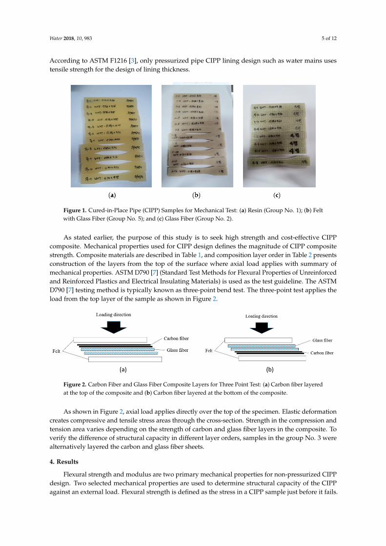
Figure 1 shows examples of the test specimens for both flexural and tensile strength measurementtests. Seven straight-bar shape specimens were cut from a composite sample plate in complianceto ASTM D790 [7] for a flexural property test. Specimens with concave-up in the middle sectionare prepared for tensile strength test, however this paper does not include results of the tensile test.
Water 2018, 10, 983 5 of 12
According to ASTM F1216 [3], only pressurized pipe CIPP lining design such as water mains usestensile strength for the design of lining thickness.
Figure 1. Cured-in-Place Pipe (CIPP) Samples for Mechanical Test: (a) Resin (Group No. 1); (b) Feltwith Glass Fiber (Group No. 5); and (c) Glass Fiber (Group No. 2).
As stated earlier, the purpose of this study is to seek high strength and cost-effective CIPPcomposite. Mechanical properties used for CIPP design defines the magnitude of CIPP compositestrength. Composite materials are described in Table 1, and composition layer order in Table 2 presentsconstruction of the layers from the top of the surface where axial load applies with summary ofmechanical properties. ASTM D790 [7] (Standard Test Methods for Flexural Properties of Unreinforcedand Reinforced Plastics and Electrical Insulating Materials) is used as the test guideline. The ASTMD790 [7] testing method is typically known as three-point bend test. The three-point test applies theload from the top layer of the sample as shown in Figure 2.
Figure 2. Carbon Fiber and Glass Fiber Composite Layers for Three Point Test: (a) Carbon fiber layeredat the top of the composite and (b) Carbon fiber layered at the bottom of the composite.
As shown in Figure 2, axial load applies directly over the top of the specimen. Elastic deformationcreates compressive and tensile stress areas through the cross-section. Strength in the compression andtension area varies depending on the strength of carbon and glass fiber layers in the composite. Toverify the difference of structural capacity in different layer orders, samples in the group No. 3 werealternatively layered the carbon and glass fiber sheets.
4. Results
Flexural strength and modulus are two primary mechanical properties for non-pressurized CIPPdesign. Two selected mechanical properties are used to determine structural capacity of the CIPPagainst an external load. Flexural strength is defined as the stress in a CIPP sample just before it fails.

Water 2018, 10, 983 6 of 12
Flexural modulus is determined from the maximum slope of a stress-strain curve produced by theload-strain graph. Table 2 presents the summary of average flexural strength and modulus in 23 CIPPsample composites acquired from total 122 testing specimens.
Table 2. Summary of Mechanical Properties.
Sample Composition AverageFlexural
Modulus (Gpa)
AverageFlexural
Strength (Mpa)
AverageThickness
(mm)
Unit Weight(g/cm3)
Group No. GroupComposition
Composition Layer Order(From Top to Bottom)
1 N Resin Only 3.38 131.00 9.83 1.23
2
TG16 0.5 mm Glass fiber 16 layers 13.84 338.33 9.79 1.70
G4 1 mm Glass fiber 4 layers 12.83 303.75 5.61 1.57
G5 1 mm Glass fiber 5 layers 12.86 371.00 6.12 1.65
G6 1 mm Glass fiber 6 layers 10.51 319.00 8.49 1.62
G7 1 mm Glass fiber 7 layers 10.88 356.50 9.05 1.60
3
F1C2G2F12 mm felt/Carbon fiber 2layers/1 mm Glass fiber 2layers/2 mm Felt 1 layers
4.68 89.50 8.71 1.42
F1G2C2F12 mm felt/1 mm Glass fiber
2 layers/Carbon fiber 2layers/2 mm Felt 1 layers
5.24 132.67 8.75 1.41
F1C4G2F12 mm felt/Carbon fiber 4layers/1 mm Glass fiber 2layers/2 mm Felt 1 layers
7.08 84.00 7.38 1.52
F1G2C4F12 mm felt/1 mm Glass fiber
2 layers/Carbon fiber 4layers/2 mm Felt 1 layers
6.87 107.50 8.21 1.49
F1C6G2F12 mm felt/Carbon fiber 6layers/1 mm Glass fiber 2layers/2 mm Felt 1 layers
5.89 84.00 9.82 1.44
F1G2C6F12 mm felt/1 mm Glass fiber
2 layers/Carbon fiber 6layers/2 mm Felt 1 layers
7.61 105.00 9.89 1.40
4
F1G2F1 2 mm felt/1 mm Glass fiber2 layers/2 mm Felt 3.59 90.67 7.31 1.39
F1G3F1 2 mm felt/1 mm Glass fiber3 layers/2 mm Felt 3.78 135.60 8.07 1.42
F1G4F1 2 mm felt/1 mm Glass fiber4 layers/2 mm Felt 4.59 158.00 9.71 1.45
F1G5F1 2 mm felt/1 mm Glass fiber5 layers/2 mm Felt 4.00 140.67 13.07 1.45
F1TG2F1TG2F1
2 mm felt/0.5 mm Glassfiber 2 layers/2 mm
Felt/0.5mm Glass fiber 2layers/2 mm Felt
4.19 121.60 8.33 1.33
F1TG4F22 mm felt/0.5 mm Glassfiber 4 layers/2 mm Felt
2 layers3.70 129.50 10.58 1.38
F1TG8F22 mm felt/0.5 mm Glassfiber 8 layers/2 mm Felt
2 layers4.15 139.33 9.74 1.49
5
TF1G4TF1 Thin Felt/1 mm Glass fiber4 layers/Thin Felt 9.00 297.43 5.84 1.54
TF1G5TF1 Thin Felt/1 mm Glass fiber5 layers/Thin Felt 9.88 352.83 6.35 1.58
F1G4TF1 2 mm Felt/1 mm Glass fiber4 layers/Thin Felt 5.60 218.25 6.97 1.44
TF1G4F1 Thin Felt/1 mm Glass fiber4 layers/2 mm Felt 5.60 171.50 7.07 1.48
The following equations are derived to calculate the thickness of CIPP from X1. DesignConsideration in ASTM F1216 [3] Appendixes. Equation (1) is for the partially deteriorated conditionwhere groundwater pressure is loading pressure over the CIPP liner. Equation (2) is for the fully

Water 2018, 10, 983 7 of 12
deteriorated condition that the existing pipe is no longer supporting external loads includinggroundwater and surrounding soil. When all other site conditions remain consistent, the CIPPliner thickness decreases proportionately to the one-third (1/3) fractional exponent of the value ofEL. According to ASTM F1216 [3], long-term modulus of elasticity (EL) is recommended as a halfvalue (50 percent) of short-term flexural modulus. The reduction ratio is assumed 50 percent of theshort-term value. For newly tested composite samples for this study, the reduction ratio follows asASTM F1216 [3] recommends. The reduction ratio for these samples shall be determined by a creeptest later. According to Equation (2), thickness of the CIPP liner is reverse proportional to 1/3 power oflong-term flexural modulus value as shown in Table 3. EL for CIPP shall be eight times stronger toachieve half of the thickness of the CIPP liner.
t =D
3√
2KELCPN(1−v2)
+ 1(1)
t = 0.721D 3
√√√√√√
(Nqt
C
)2
ELRWB′E′s
(2)
where, t = thickness of CIPP, D = mean inside diameter of original pipe, K = enhancement factor ofthe soil and existing pipe adjacent to the new pipe, EL = long-term modulus of elasticity for CIPP,C = ovality reduction factor, P = groundwater load, N = factor of safety, qt = total external pressure onpipe, Rw = water buoyancy factor, B’ = Coefficient of elastic support, and E’s = modulus of soil reaction.
Table 3. Thickness table.
Thickness Flexural Modulus Thickness (Changing Expression)
t1 EL1 t1
t2 EL2 = 2 × EL1 t2 = 13√2
t1
t3 EL3 = 8 × EL1 t3 = 13√8
t1 = 12 t1
As a number of glass fiber layers increase, the magnitude of the applied load positively andlinearly increases as shown in Figure 3. The result of the group No. 2 verifies that the glass fibereffectively reinforces its structural capacity. Samples made out of glass fiber sheets and resin positivelyexceed 10 Gpa in Flexural modulus that surpasses at least six times that the minimum value proposedby ASTM F1216 [3]. Average thickness for G4 in the group No. 2 is less than 6 mm, and unit weight is1.57 g/cm3. It verifies the effectiveness of the glass fiber reinforcement in this application. Figure 3shows that Equations (1) and (2) are suitable to apply the design of the glass fiber reinforced CIPP linerwithout a significant modification.
Figure 4 presents the flexural modulus of all sample groups. Notably, carbon fiber reinforcementwith glass fiber is not significantly increasing flexural modulus. Felt–Glass fiber–Carbon fiber–Felt(FGCF) composite shows the higher value of the flexural modulus than Felt–Carbon fiber–Glassfiber–Felt (FCGF). It means that glass fiber layer takes higher compressive stress than tensional stress.The effectiveness of glass fiber reinforcement between 2 mm regular felt layers is presented in GroupNo. 4 in Table 2. Hypothetically, the authors presumed that the samples in the group No. 4 andNo. 2 behave alike. However, glass fibers with 2 mm regular felt fail to attain a sufficient level ofstructural reinforcement. Figure 4 indicates that 2 mm Felt–Glass fiber–2 mm Felt (FGF) composites isnot effective as expected. The flexural modulus in the group No. 4 is only increased less than 1 Gpafrom the baseline value in the group No. 1. In addition, a combination of 0.5 mm thin felt and 2 mm felt(FGTF) shows an insignificant increment of the flexural modulus. In summary, all samples used 2 mmfelt are incapable of increasing flexural modulus and strength as expected. The most noteworthy resultis found from a composite made of multiple glass fiber layers with two thin felt layers (TFGTF) as

Water 2018, 10, 983 8 of 12
shown in the group No. 5 in Table 2. Range bar for TFGTF in Figure 4 demonstrates flexural modulusresults. The average modulus value is slightly lower than the fiberglass layer (G), which shows thehighest flexural modulus. The less felt uses in the composite, the higher flexural modulus is obtained.
Figure 3. Load for Glass Fiber Composite Samples.
Figure 4. Summary of Flexural Modulus. Note: Nomenclature of the composite sample groups isincluded in Table 1.
Figure 5 presents stress-strain relations acquired from three-point bend tests. The deflection ofCIPP is the decrease of the vertical diameter due to external load on the CIPP. Partially deterioratedpipe rehabilitation is not designed to withstand significant external load-bearing capacity. However,CIPP in fully deteriorated pipe rehabilitation condition should tolerate all external loads. Thus, theCIPP deflects and the deflection is used in the design process. The most design guidelines allow amaximum of 5 percent and CIPP is treated as a flexible pipe. Deflection of the pipe is related to thestiffness. Higher stiffness of the pipe means that it is less flexible and has higher flexural modulus.Figure 5a indicates that glass fiber composites exhibit the highest flexural strength and modulus as

Water 2018, 10, 983 9 of 12
compared to all other sample groups. However, deflection at the maximum flexural stress before thefracture is significantly below five (5) percent, which ranges between 3.0 and 3.5 percent. Other samplegroups using regular 2 mm felt layers in Figure 5b,c exhibit similar deflection patterns to the resin(N). Figure 5d,e show the carbon fiber is highly stiff at the beginning, but it fails less than 3 percentdeflection. Figure 6 illustrates an example of carbon fiber layered samples that fractured and clearlydelaminated after three-point bend tests. It is found that the unsaturated polyester resin used fortypical CIPPs is not suitable to acquire sufficient bonding strength with carbon fiber. Dong et al. [14]tested carbon fiber reinforced epoxy hybrid composites. Substituting carbon fibers in lieu of glassfibers potentially improve the flexural strength and modulus.
Figure 5. Stress-Strain (Deformation) Relation: (a) N: Rein; (b) G: Glass Fiber; (c) FGF: Felt-GlassFiber-Felt; (d) FCGF: Felt-Carbon Fiber-Glass Fiber-Felt; (e) FGCF: Felt-Glass Fiber-Carbon Fiber-Felt;and (f) TFGTF: Thin Felt-Glass Fiber-Thin Felt.

Water 2018, 10, 983 10 of 12
Figure 6. Carbon Fiber Fracture and Delamination.
This study was not able to verify the effectiveness of carbon fiber reinforcement. Polyester resindemonstrates relatively higher shrinkage during curing time causing cracking at the interface withcarbon fiber. The bonding strength of epoxy is significantly higher than polyester resin. Therefore,the structural effect of the composite CIPP liner using polyester resin does not enhance mechanicalproperty and the specimens were fractured at low deflection as shown in Figure 5d,e.
The stress and strain relations of a composite with thin felt and glass fiber are shown in Figure 4f.Unlike other composites, these particular composites enhance both flexural strength and stress-strainrelation. The flexural strength approximately reached at 400 Mpa and stress-strain continuouslyincreases up to 5 percent. This implication indicates an apparent hybrid effect of combining twodifferent materials. There is another benefit of using the thin felt as out liners. It is vital for CIPPbecause glass fiber layer needs a form of the container holding liquid state resin for impregnationand installation in the existing sewer pipe before the curing process. This composite shall be furtherstudied for development of a high strength CIPP composite material technology and construct for afuture CIPP pilot test.
5. Conclusions
This paper presents a summary of mechanical test results and a comparison study of the variouscomposite materials for CIPP rehabilitation. A total of 122 specimens in 21 composite sample groupswere made by the manual hand lay-up process in between two stainless steel plates and used normalhot water unsaturated polyester curing. Three-point bend tests were conducted in accordance withASTM D790 [7].
Glass fiber and carbon fiber were used to enhance mechanical properties including flexuralstrength and modulus. Carbon fiber reinforcement with the polyester resin was unsuccessful toincrease any of the proposed mechanical properties significantly. Specimens made of glass fiberincrease flexural modulus up to eight times of the ASTM minimum short-term flexural modulus asthe experiment desired. However, the glass fiber liner in Figure 5a fractured significantly less than4 percent that is not intended engineering property for conventional flexible pipe materials includingCIPP liner material. It means that the glass fiber liner has the highest stiffness among all samples. Itcan be applied to a rigid pipe rehabilitation such as concrete pipe, but not the best suitable for a flexiblepipe rehabilitation such as PVC and HDPE pipes which typically allow maximum deformation at5 percent. Another critical problem to impregnate resin in the CIPP liner and install in the constructionsite without the impermeable film that holds resin in the liner. Therefore, a composite layer made ofthe glass fiber and thin felt layers yielded the best outcomes.

Water 2018, 10, 983 11 of 12
The thin felt consists of the top and bottom layers of the composite, and take approximately 20percent of the total thickness. The thin felt layer with impermeable film coating holds resin during theimpregnation and installation process while glass fiber layers increase flexural strength and modulus.This composite enhances not only mechanical properties including flexural strength also a degree ofdeflection above 4 percent. The additional thin felt layers improve the flexibility of the compositeand exhibit slow failure mode as shown in Figure 5f. Based on the findings from this study, theauthors conclude that the thin felt layer can serve a resin containment bag during resin impregnationprocess and an internal barrier for resin curing. Glass fiber layers significantly improve the mechanicalproperties. This combination of two proposed materials can be used as a composite for a high strengthCIPP layer development for sewer and potentially water conveyance system rehabilitation applications.
The future research plans to seek simultaneously increasing deformation up to 5 percent andmechanical properties such as flexural strength and modulus.
Author Contributions: Conceptualization, H.W.J.; Data curation, J.K.; Formal analysis, J.K.; Investigation, J.K.;Methodology, H.W.J. and D.D.K.; Project administration, D.D.K.; Supervision, S.S.Y.; Writing—original draft,H.W.J. and D.D.K.; Writing—review and editing, S.S.Y.
Funding: This subject is supported by Korea Ministry of Environment (MOE: 2017-0007-00001) as “PublicTechnology Program based on Environmental Policy.”
Acknowledgments: We acknowledge the anonymous reviewers for their valuable comments.
Conflicts of Interest: The authors declare no conflict of interest.
References
1. ASCE. 2017 Infrastructure Report Card—A Comprehensive Assessment of America’s Infrastructure.Available online: https://www.infrastructurereportcard.org/wp-content/uploads/2016/10/2017-Infrastructure-Report-Card.pdf (accessed on 24 July 2018).
2. Najafi, M.; Gokhale, S. Trenchless Technology: Pipeline and Utility Design, Construction, and Renewal;McGraw-Hill: New York, NY, USA, 2005.
3. ASTM International. Standard Practice for Rehabilitation of Existing Pipelines and Conduitsby the Inversion and Curing of a Resin-Impregnated Tube. 2009. Available online: https://scholar.google.co.kr/scholar?hl=ko&as_sdt=0%2C5&q=Standard+practice+for+rehabilitation+of+existing+pipelines+and+conduits+by+the+inversion+and+curing+of+a+resin-impregnated+tube&btnG=(accessed on 24 July 2018).
4. Allouche, E.; Alam, S.; Simicevic, J.; Sterling, R.; Condit, W.; Matthews, J.; Selvakumar, A. A pilot studyfor retrospective evaluation of cured-in-place pipe (cipp) rehabilitation of municipal gravity sewers. Tunn.Undergr. Space Technol. 2014, 39, 82–93. [CrossRef]
5. Water Authorities Association. Sewerage Rehabilitation Manual; Water Research Center: London, UK, 1990.6. Standard ATV-DVWK-A 127E: Static Calculation of Drains and Sewers. 2000. Available online: https:
//dokumen.tips/documents/atv-dvwk-a-127-e-static-calculations-of-drains-and-sewers.html (accessedon 24 July 2018).
7. ASTM Inernational. Standard test methods for flexural properties of unreinforced and reinforced plasticsand electrical insulating materials. Astm d790. In Annual Book of ASTM Standards; ASTM Inernational: WestConshohocken, PA, USA, 1997.
8. Riahi, A.M. Short-Term and Long-Term Mechanical Properties of Cipp Liners. Master’s Thesis, University ofWaterloo, Waterloo, ON, Canada, 2015.
9. Straughan, W.T.; Guice, L.K.; Mal-Duraipandian, C. Long-term structural behavior of pipeline rehabilitationsystems. J. Infrastruct. Syst. 1995, 1, 214–220. [CrossRef]
10. North American Society for Trenchless Technology. Nastt’s Cured-in-Place (Cipp) Good Practices Guidelines;North American Society for Trenchless Technology: Cleveland, OH, USA, 2015.
11. Nassar, R.; Yousef, M. Analysis of creep failure times of cured-in-place pipe rehabilitation liners.Tunn. Undergr. Space Technol. 2002, 17, 327–332. [CrossRef]
12. Matthews, J.C. Large-diameter sewer rehabilitation using a fiber-reinforced cured-in-place pipe. Pract. Period.Struct. Des. Constr. 2014, 20, 04014031. [CrossRef]

Water 2018, 10, 983 12 of 12
13. Akinci, A.; Güleç, A.; Yilmaz, F. The Applicability of Grp and Nrp Composites in Rehabilitation ofUnpressurized Pipes. In Advanced Materials Research; Trans Tech Publications: Zürich, Switzerland, 2010;pp. 563–570.
14. Dong, C.; Davies, I.J. Flexural properties of e glass and tr50s carbon fiber reinforced epoxy hybrid composites.J. Mater. Eng. Perform. 2013, 22, 41–49. [CrossRef]
© 2018 by the authors. Licensee MDPI, Basel, Switzerland. This article is an open accessarticle distributed under the terms and conditions of the Creative Commons Attribution(CC BY) license (http://creativecommons.org/licenses/by/4.0/).