Embed Size (px)
Citation preview

JULY 1949
THE MEASUREMENT OF CHANGES IN LENGTH WITH THE AID OFSTRAIN GAUGES
by A. L. ~IERMASZ and H. HOEKSTRA. 621.317.39 :630.172.222
For some decades the technique of measuring electrical quantities has been ahead of thatfor the measurement of other, e.g. mechanical, quantities, as far as sensitivity and convenienceare concerned. This advance has been further augmented by the development of amplifiers,cathode-ray oscillographs and the like. It is therefore obvious that this advanced techniqueshould also be made available in other fields' of measuring by means of instruments designedfor converting non-electrical into electrical quantities. An example of such an instrument isthe strain gauge dealt with in this article, which shows differences in resistance when itslength is chatiged, which can be measured electrically. In engineering there are wide fields ofapplication for strain gauges in combination with a measuring bridge and/or a cathode-rayoscillograph.
.-
A fundamental problem in the dimensioning ofany mechanical constructiori is the distribution ofstresses arising under different conditions ofload-ing. Only with the knowledge of this distributionof stresses - together with the necessary knowledgeof the properties of materials - can ,cSmearrive atthe ideal construction which is nowhere too weaknor anywhere unnecessarily strong."However; if the construction is complicated great
difficulties" are encountered in calculating the dis-tribution of stresses. One must therefore often resortto practical measurements on existing con-structions (or models). Usually measurements canonly be taken on the surfaces, but it is just therethat the stresses are as a rule greatest. As a mea:sure for the stress in for instance a rod or bar undera tensile load one takes- the change in length ofthe rod, for as long as the deformation is elastic,it is proportional to the stress. In more complicatedcases the stress can be deduced from the changesin length measured in two or "three directions.
For carrying out these measurements. there areextensometers with which it is possible to deter-mine the changes taking place in the distance be-tween two suitably chosen points of the construe-tion when the load acting upon it varies. In order tomeasure this change in distance with sufficientaccuracy either mechanicalor optical extenso-meters are employed which magnify the movementwith the aid of a set of levers or by optical meansbefore the actualmeasurement is made.For simple cases with a static load these exten-
someters are quite practicable, but they are of nouse with more complicated constructions, in placesdifficult "to get at or where vibrations th~t are notof a very low 'frequency must be accounted for.We have only to take as an example aircraft con-
struction, where varrataons in length have to bemeasured during the flight, often at some hundredsof points at the same time, on the wings, fuselageand tail planes, -whilst moreover large vibrationsmay be superimposed on the static load. In suchcases the solution of the problem is offered by whatare known as strai~ gauges, with which varia- "tions in length are measured by electrical means,this method" possessing, moreover, advantagesover extensometers.
Principle and advantages of strain gauges
It has been known for some' time that the elec-trical resistance of a wire changes with the mechan-ical stress in the wire; Lord Kelvin describedthis phenomenon as far back as 1856. This formsthe fundamental principle of. strain gauges, sincethese consist of a wire which is glued onto theconstructional ,element under test in such a way .that it undergoes all the changes in length takingplace in that part of the structure. The measuredresistance variations of the wiré then give a mea-sure of the change in length. It is only during thelast ten years, however, that in several countriesstrain gauges have been developed with it sufficientdegree of reliability. . .The main reasons why the method of measuring
with strain gaug~s has come to be so widely appliedare the following:1. The gauges are only a few centimetres long and
can thus he applied in places which wouldotherwise be almost inaccessible.
2. The measuring instrument proper is set upat a distance and if desired can be connectedsuccessively to a large number of strain gauges.
3. By this method also dynamic loads (vibra-tions) can he measured.
23

24 PHILIPS TECHNICAL REVIEW VOL. n, No. 1
4. In combination with an oscillograph it ispossiblea) to record the observations photographi-
cally,b) to observe and record simultaneously
the resistance variations of two or more straingauges.
Construction, components and use of strain gauges
Fig. la is a sketch of the larger of the two typesof strain gauges made by Philips. It consists of aresistance wire of constantan (55 % Cu, 45% Ni)
b 56632
Fig. 1. a) Sketch of the strain gauge GM 4472. A resis-tance wire, B = leads, C = paper carrier (actual size), D =paper covering strips. b) Carrier of the strain gauge GM 4473(actual size).
bent in zig-zag fashion and glued onto a papercarrier. By means of this carrier, when glued ontothe object to be tested, the variations in length ofthe object are faithfully translated in the wire,whilst at the same time the carrier provides elec-trical insulation. Connected to each end of theconstantan wire by a soldered joint is a copper
lead wbich is also partly glued onto the paper carrier,thereby providing sufficient safeguard against anystrain on the leads being transmitted to the thinconstantan wire. The resistance of this gauge is600 ohms.The smaller type (GM 4473, fig. lb) is of a
similar construction but has a resistance of 120ohms. Owing to its smaller dimensions it can beapplied in even less accessible places more easilythan the larger type (GM 4472), which, however,with its larger surface, can dissipate a greaterpower, thus allowing of more sensitive measuring.
Fig. 2 shows a specimen of each of the two typesand the cases in which the strain gauges ale suppliedin packets of 10. The frequency range of thevibrations covered by the strain gauge extends toabove 10,000 cis.We shall nowdiscuss first the principal components
of the strain gauge: the resistance wire, the glueand the paper carrier, and then the method ofgluing.
The resistance. wire
Since the relative resistance variation, even withthe greatest elongation occurring, is only small(in the order of 0.1%), one has to guard against theeffect of accidental resistance variations that mayoccur for instance in switches Ol in the long connec-tions often necessary between the strain gauge andthe measuring instruments. It is therefore essentialthat the resistance of the strain gauge should be atthe least in the order of 100 ohms. In order to get
Figl 2. 1 = strain gauge GM 4472, 2 = strain gauge GM 4473; also the two cases in whichthe strain gauges are sold.

JULY 1949 STRAIN GAUGES' 25
such a resistance in the strain gauge only a few~entimetres long with a reasonably robust wire, amaterial has to be used which possesses a high'specific resistance. This excludes the pure me-tals and leaves only alloys like constantan andchromium nickel, and carbon.
In the second place the choice of material for thewire is determined by the behaviour of the gaugefactor k, that is the ratio of the relative variationiJRIR of the resistance to the relative variationiJlil of the length:
iJR iJL iJR 1k =.-:-=-'-.
R IRe
(iJljl =: e is also called the elongation.) Thegreater the value of k (absolute), the higher is thesensiti vity of the measurement, but a liD.ear relationhetween iJRjR and e (i.e. a gauge factor whichis independent of the amount of the elongation)is even more important.
/
%//
0,6!JR /R 2/t /
/0,4 /
//
0,2 //
h _e-q3 -q2 -0,1
'I0,1 q2 0,3%
// -a2/
.~// -a4'J,// ../ ,..0,6// :;6633
/Fig. 3. The relative resistance variations .tJR/R as function ofthe elongation e, (1) for constantan, (2) approximate curveof a non-linear relation as found with chromium nickel.
The high k value found with carb~n (about 20),which is due to the changeability of the transferresistance between the particles of carbon, makesit tempting to use this material in strain g~uges 1),hut the results in the long run are not sufficientlyreproducible and' as a consequence carbon is notused as a material for the resistance ele~ent anymore.
The relation between. iJRjR 'and e forconstantan.1) See for instance S. L. de Bruin, The investigation of
rapidly changing mechanical stresses with the cathode-rayoscillograph, Philips Techn. Rev. 5, 26-28, 1940.
is represented hy the continuous line in fig .. 3.This relation is practically linear, with k ~ 2 bothin the elastic area (c between + 0.2%) and outsideit. With other alloys having a high specific resis-tance this relation is a non-linear one: chromiumnickel for instance gives a value of k ~3 for a smallelongation, this value dropping to about 2 in theplastic area, as roughly. indicated hy the brokencurve in fig. 3. This non-linear characteristic is agreat disadvantage in practice an~ explains whyconstantan is preferred.The resistance of a conductor varies not only
with the elongation but also with the temperature.Where only a rapidly changing elongation has to bemeasured (vibrations) gradual variations in resis-. tance due to temperature fluctuations are not dis-turbing, but in the case of static loads they maywell he so. We shall presently discuss a methodwhereby the influence of temperature is compen-sated, hut it is nevertheless desirable that thetemperature coefficient (a) of the strain gaugeshould he as small as possible. In this respect, too,constantan is highly favourable, a being in theorder of 1 X .10-6 compared with ahout 100 X 10-6for chromium nickel.In table I the quantities discussed are listed for
constantan, chromium nickel, carbon and, for com-parison, a pure metal (iron).
Table I. Approximate values of the specificresistance e, the .gauge f~ctor k ~ (t.1R/R): e (within the limits of elasticity)and the temperature coefficient a of the resistance of somematerials.
Máterial Ilo e k a(LO'm
..,10-6 eC)-l
Iron.,.
0.1 '-4 5000. Constantan .0.5 2, 1-3Chromium nickel 1 " 3 100Carbon 70 '~O' -500
'"Here wc .can go rather more deeply into the value of the
gauge factor k of metals, ' •• . .The resistance of a wire with diameterD is:
R =' -__!_g__ .:!!:D2'4
When the wire is stret~hed . (or compressed) not only lchanges hut also D mid e. As regards the' change in diameterPoisson's rel~tion applies; ' ' ,
. (1)
; dD. dl-]):1'=(L,
iri which-for mostmetals; In.rhe elastic ar!!a, IJ. I':::l 0.30-0.35 •.As regards the specificresistance (! it is known that when ametal is subjected to compressive forces from all .sides (!
changes with the density, thus with the volume V. In the case
26 PHILIPS TECHNICAL REVIEW VOL. Il, No. 1
of constantan we then have the linear relation
d dV .e. c .e·V='··· .with c = 1.13. We shall assume, as Opechowski does,that this relation also holds for extension and contraction.Since V = 1/47CD2l equation (1) can be written as follows:
R = el2•.V
By differentation we arrive at
dR do dl dV dVlf= ; + 2 -l--v-=2c+ (c-I)V' (3)
Plastic deformation is characterized by cons.ancy of thevolume, hence for all materials (even if eq. (2) does not hold)the rule applies that
.dRlf=2e,
ork = 2,
in accordance with experiment.With elastic deformation on the other hand
so that (3) becomes
dR1f = 2e + (c-I) (1-2(1.) e,
ork = 2 + (c-I) (1-2(1.) •
For eonstantun, with c = 1.13 and (1.= 0.325, this worksout to
k = 2 +0.13 X 0.35 = 2.05,
which falls within the extreme vuluesmeasured (2.09 ± 0.06).It must be said however that with other materials the agree-ment is much less satisfactory.
The glue and the paper
The paper carrier and the glue used for fixingthe constantan wire on the carrier and the latter.to the object to he tested have to translate the'. deformations of the object faithfully to the wire.Consequently the adhesive strength ofthc gluemust he exceptionally high. The hest kinds of glueare those having a cellulose base and consisting oflong molecules with numerous polar atom groups.It is the latter which result in the' strong adhesion(hoth to paper and to metal) and, moreover, showpractically no after-effects (creep).
After-effects in a strain gauge constitute a mostundesirable property, because then the unambigu-ous relation between resistance variation and.defor-mation is lost. Both in the wire as well as in theglue and the paper after-effects must therefore bekept small in comparison with other inaccuraci~sin the measuring method. This is a requirement thatis particularly difficult to meet as regards the glue,but in the manufacture of the Philips strain gauges
(2)
this has been satisfactorily met. With all. elongationof 0.1% for instance the permanent relative resis-tance change is normally less than 10-5•The long molecules of cellulose glue have the
property of adapting themselves somewhat to thedirection of the elongation, thus lending greattoughness to the adhesive layer. Other kinds ofglue on the other hand become more or less brittle(for instance polysterene, which moreover is lesspolarized than cellulose glue).
Finally the glue must not take too long to dry;this we ~ refer to farther on when dealing with the'method of gluing .The thinner and more porous thepaper, the quicker does the glue dry, and-for thisreason the thinnest possible paper is used for thePhilips strain gauges, having regard to insulationand the necessity for the gauge to remain flat.For gluing strain gauges onto the objects to be
tested, Philips have placed on the market tubes ofglue (GM 4479) which can be used at temperaturesup to 60°C.
Gluing on the strain gauges
In order to ensure proper adhesion of the straingauge to the object heing tested, at the place whereit is to be applied. the metal must be thoroughlycleaned first with emery paper and then with somegrease-remover, for instance pure acetone. Thecleaned surface must not then be touched with thehands. A thin layer of glue (GM 4479) is then spreadout over it and when this is dry the back of thestrain gauge is likewise covered with a thin layerof glue and pressed down on top of the other layer,taking care that the longitudinal axis of the straingauge coincides exactly with the direction of thedeformation to be meas'ured.After about 6 hours the glue is. dry enough and
the adhesion is sufficient for taking rough mea-surements with the strain gauge. For accuratemeasurements, however, particularly when theyare to be of a long duration, the glue should beallowed to dry a few days, preferably while heatingto 70°C. Even after that every possible precautionshould be taken to exclude moisture, since mois-ture has a serious ~ffect upon the measuring results,due to two causes: variable insulation resistance andvariable mechanical stress both in the glue and inthe paper. As regards the insulation resistance, if forinstance' with a strain gauge of 600 ohms. it isdesired to measure resistance variations of 0.1%with no greater error than 1% then the insulationresistance (in parallel with the strain gauge) ,*-&uldanswer high demands of constancy if iC"wèreonly in the order of 60 megohms. If, on the other

JULY 1949 STRAIN GAUGES 27 /
hand, it is of the order of 1000 megohms, as isto be reached with the above-mentioned measures,then great changes in the insulation resistance'are harmless.
In the second place moisture causes local swellingof the glue and of the fibres of the paper. Even in aglued-on strain gauge, which is not free to expand,such deformations are apt to arise and cause per-ceptible, irregular resistance changes .. Precision measuiemente of long duration should
not he begun until the insulation resistance hasreached 500 M.n. The gauge must then be shut offfrom the air either with a layer of wax or with asheet of rubber glued round the gauge and enclosingat the same time a moisture-absorbing substance(silica gel). This latter method has been developedin the Laberatory for Applied Mechanics of theFoundation for Technical-Industrial Research("T.N.O.'')' at Delft (Netherlands), with whichinstitution we are fruitfully cooperating in this field,It is a metho~ that has proved to be very satisf~ctory,even when taking measurements over a long' periodin the open air in rainy weather.
The. measuring apparatus
We shall now proceed to discuss the apparatusemployed for measuring small resistance varia-.tions. A Wheatstone bridge where one branchis formed by the strain gauge (Cl infig. 4) is suitablefor this, though in some: cases, as will be shown
p
'----------1 "-}-- ....I
VFig. 4. Wheatstone bridge with an active and a dummygauge (G1 and G2). V = alternating voltage supply, P =potentiometer for balancing the bridge, A = 'amplifier, 1=indicator.
presently, a' simpler system 'may also answer thepurpose. The bridge circuit, however, is to be pre-ferred whenever the influence of temperature hasto be excluded. The following will show what thiseffect is.
The effect of temperosure
When the temperature of the object to which thestrain gauge is' affixed changes while the mea-surements are being taken this may lead to twoerrors:
1) The resistance variation observed in the straingauge is partly due to the temperature coeffi-, cient of constantan, small as it may be; this partof the variation must not be interpreted as adeformation.
2) Even in the absence of stresses the object under-goes deformation, namely thermal expansion,which it is not as a rule desired to measure butwhich shows itself as a variation of the resistanceof the strain gauge because of the usuallydifferent expansion coefficient.
Both these errors can for the greater part beavoided by using a c om p ens a t.i n g or dummystrain gauge in the bridge circuit. Thisis a strain gauge .of the same type as the "active" or primary gauge Cl(fig. 4); it forms an adjacent branch of the bridge,(C2)· It is glued onto the same material as Cl butthis piece of materialIs not mechanically loaded,and the dummy gauge has tc! be' placed clo~eenough to the actual measuring' point so that itundergoes the sam~ temperature variations as theactive strain gauge. Thus .the active and the dummy, gauges are subject to the same thermal fufluences.The resistance variations resulting cancel eachother in the bridge circuit, so that only the varia-tions which correspond to mechanical stresses inthe object are measured.
Often it is possible to fix the dummy gauge insuch a way that it not only compensates the thermaleffect 'but also contributes towards the unbalance ofthe bridge, so that the measuring system becomesmore sensitive. In such a case the compensatinggauge is fixed at a place on the object where thematerial is subject to contraction while the "primary"gauge undergoes an elongation, or vice versa. Weshall come across some examples of this farther on.
The two types of measuring bridge developedfor use with strain gauges have both been designedfor working with a compensating gauge.
We shall now consider the measuring bridgesmore closely.
Measuring bridge [or static load'
The diagram of fig. 4 represents the principle ofboth types of measuring bridge. Before the active
. gauge (Cl) is deformed, the bridge is balanced withthe aid of the potentiometer P, that is to say, thedeflection of the indicator I is set to zero. In ~rderto increase the sensitivity the' indicator is precededby an amplifier. So as not to complicate the latterthe bridge is not fed with D.C. but with an alter-nating voltage (derived from a valve oscillator in-corporated in the apparatus).
28 PHILIPS TECHNICAL REVIEW VOL. 11, No. 1
Owing to au alternating voltage being used, the bridge mustalso be balanced capacitively. The measures taken for thisare not indicated in fig. 4 and we shall not go into them here.
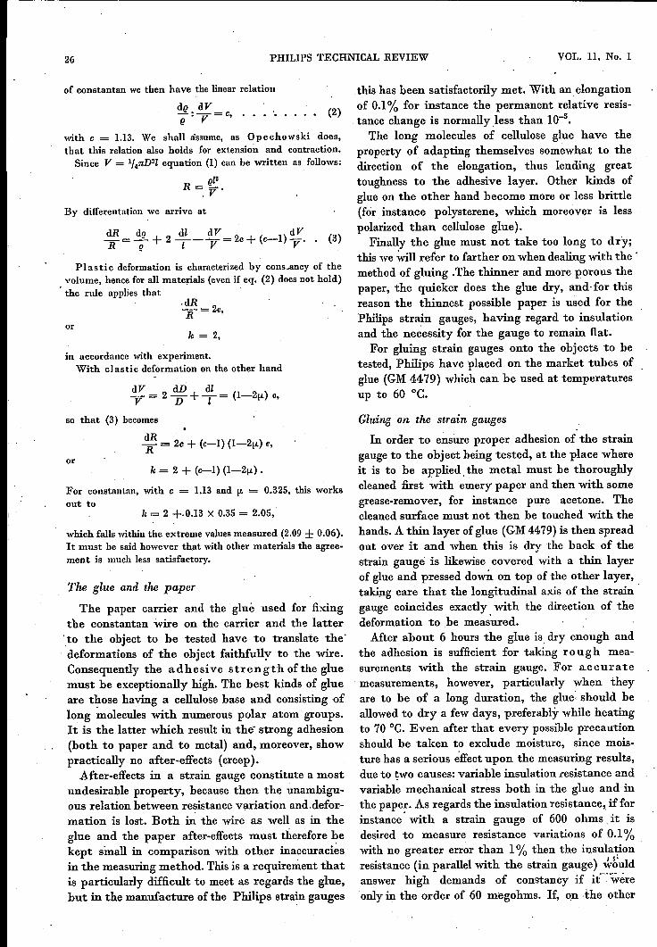
Fig. 5. Measuring bridge (GM 4571) using the zero method formeasuring static loads. To the right, one above the other,three knobs for balancing the bridge; to the left, from top tobottom, the indicator, the correcting knob for the gaugefactor of the strain g<luge, and the knob for switching on andoff, acting at the same time as the switch by means of whichthe indicator can be used for checking the batteries.
Deformation of the active strain gauge will throwthe bridge out of balance. As is known, one can thenproceed in two ways:a) rebalance the bridge with the potentiometer P
and determine the resistance variations fromthe two positions of P;
b) use the deflection of the indicator as a directmeasure of the resistance variation of Cl'
The measuring bridge of the type GM 4571(jig. 5) works on the zero method mentioned sub(a). This has the advantage that the result is inde-pendent of the degree of amplification, but on theother hand it is of course limited to static loadonly.The potentiometer is provided with a scale from
which the elongation can be read directly. In orderto allow for the fact that there is a slight differencein the gauge factor k as between one strain gaugeand another, a correction knob is provided whichhas to be previously set in the position correspond-ing to the gauge factor of the strain gauge used.This f~ctor is shown on the strain gauge case (fig. 2).As indicator a moving-coil meter is used, which
is connected via selenium rectifiers 2) to the outputof the amplifier, and the indicator can be used at thesame time as a voltmeter for checking the batteriesfeeding the oscillator and the amplifier. Thesebatteries make the bridge particularly suitable fortaking measurements in places where no A.C. mainsare available.
2) J. J. A. Ploos van Amstel, Small selenium rectifiers,Philips Techn. Rev. 9, 267-276, 1947.
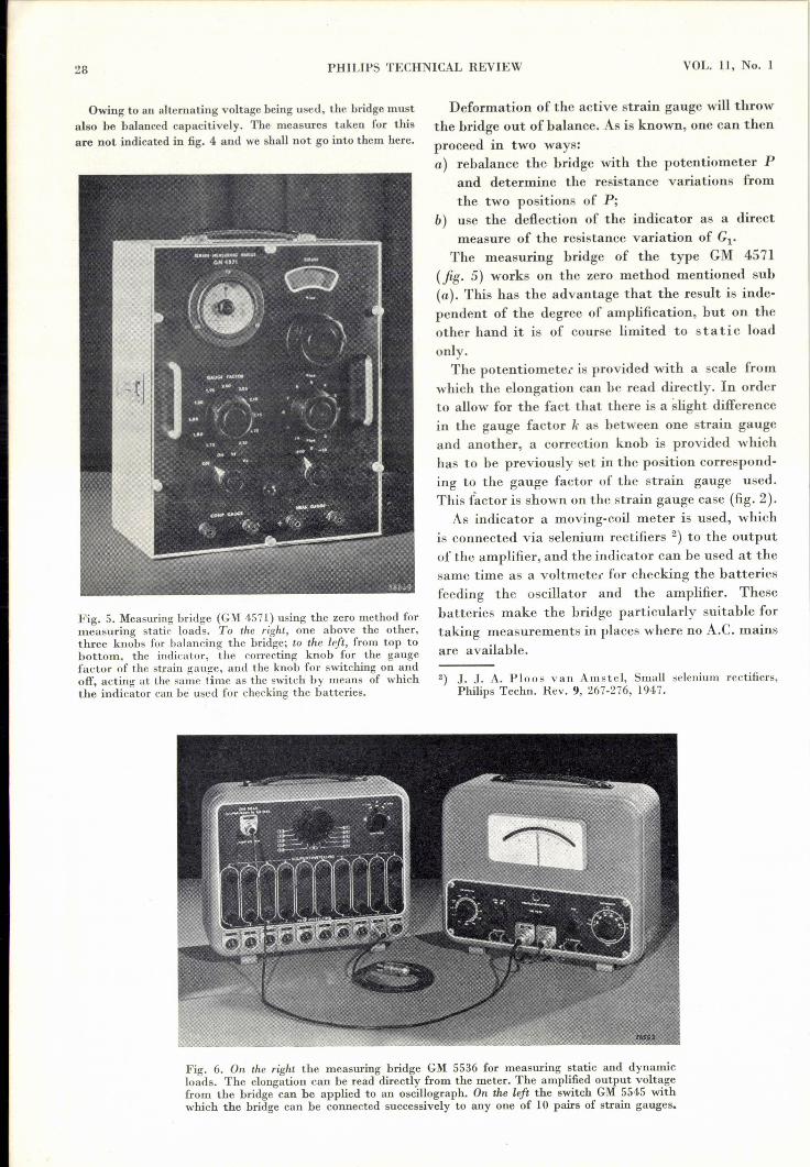
Fig. 6. On the right the measuring bridge GM 5536 for measuring static and dynamicloads. The elongation can be read directly from the meter. The amplified output voltagefrom the bridge can be applied to an oscillograph. On the left the switch GM 5545 withwhich the bridge can be connected successively to anyone of 10 pairs of strain gauges.

JULY 1949 STRAIN GAUGES 29
This bridge is suitable for use with strain gaugesof more than 100 ohms resistance.
Measuring bridge for static and dynamic loads
The measuring bridge of the type GM 5536(fig. 6) is used in the manner indicated aboveunder (b).This bridge has to he balanced before starting to
take measurements. When the balance is disturbedit produces an output voltage which in the case ofdynamic load is a modulated alternating voltage;the "carrier" of the oscillator feeding the bridgeis modulated with the frequencies of the mechanicalvibrations. With the aid of a ring modulator 3) con-sisting of four selenium rectifiers, the output voltageis demodulated and converted into a rectified vol-tage which is fed to a moving-coil meter acting asindicator. Static load is to be regarded as a specialform of dynamic loading where the frequency of thevibrations is zero. Both for static and for dynamicloads the deflcction of the meter is a measure of theresistance variation of the strain gauge.
Instead of the meter, a cathode-ray oscillographcan be used as indicator. By this means the vibra-tions can he visualized and if necessary recordedphotographically. In ordel to avoid distortion anoscillograph should be used which has an amplifiersuitable for the very low frequencies that may occurwith mechanical vibrations. Such an oscillograph isfor instance the type GM 31564), which is suitablefor frequencies down to 1 cycle per second.As an accessory for the measuring bridge GM
5536, which is intended for use with strain gaugesof 600 ohms (and if need be higher), a change-overswitch is provided {fig. 6), by means of which thebridge can be quickly connected in succession to 10different combinations of an active and a dummystrain gauge. The change-over switch is providedwith a device by means of which the meter orthe oscillograph can be calibrated.A cathode-ray oscillograph offers the possibility
of visualizing simultaneously the resistance va-riations of two or more strain gauges, so that timeand phase differences of the vibrations can hedetermined. For that purpose one or more electronicswitches 5) can be used.
Circuit for an exclusively dynamic load
If measurements have to be taken only under a
3) See e.g. Philips Techn. Rev. 7, 86, fig. 6, 1942.4) S. L. de Bruin and C. Dorsman, A cathode-ray os-
cillograph for use in tool making Philips Techn. Rev. 5,277-285, 1940.
6) See e.g. E. E. Carpentier, An electronic switch withvariable commutating frequency, Philips Techn. Rev. 9,340-346, 1947.
dynamic load then no account need be taken ofgradual variations due to temperature fluctations.In that case a compensating strain gauge and abridge circuit ale superfluous and one can manage
o56635o
Fig. 7. Circuit for measuring dynamic loads. B = battery(45 V), R = series resistor, G= strain gauge, A = pre-ampli-fier, 0 = oscillograph.
quite well with the simple arrangement illustratedin fig. 7, where the strain gauge is connected to abattery via a resistor. Resistance variations of thestrain gauge set up across its terminals voltage
Fig. 8. The pre-amplifier GM4570, which is suitable for thearrangement according to fig. 7. Gain 4 times or 20 times.
variations which are applied to an oscillograph viaa pre-amplifier.As pre-amplifier use can he made of the unit
illustrated in fig. 8.The sensitivity of the oscillograph can be calibra-
ted with a known alternating voltage.
Applications
The applications of strain gauges in engineeringcan he divided into direct and indirect appli-cations. Under the former are to be understoodcases where -strain gauges are used for measuringstresses in all sorts of mechanical constructions,whereas indirect applications cover their use withaccessory apparatus required for taking variousmeasurements.

30 PHILlPS TECHNICAL REVIEW VOL. 11, No. 1
Direct applicationsAn extensive field for the use of strain gauges lies
in the measuring of stresses in bridges, cranes,ships, aircraft, rolling mills, etc. As remarked in theintroduction, better knowledge of the stressesoccurring leads to more rational constructions withmore reasonable margins of safety.
Of the numerous examples of the successful directapplication of strain gauges we shall mention hereonly three,In the first place there are the measurements
taken on the hull of a ship at the time of launching,when a very complicated state of stress may occur.In order to measure the changes taking place in thestresses at a certain point of the ship's hull threestrain gauges are applied at that spot close to-gether at angles of 120°. The state ~f stress canthen be easily calculated from the resistancevariations of the three gauges.A second example is the measuring of torque
in a shaft. Two strain gauges are glued onto theshaft with an angle of 90° between them and at anangle of 45°with the centre line of the shaft (fig. 9).When torque arises one of the gauges is stretchedand the other contracted. The torsion is calculated
a
Fig. 9. Torsional vibrations in a shaft can be measured withtwo strain gauges at right angles to each other and makingan angle of 45° with the centre line of the shaft. (In the expe-riment illustrated here four gauges were used, connected inparallel in pairs.)
from the resistance variations of the two gauges.As third examplefig. 10 shows the set-up used for
measurements which were taken in cooperationwith the Netherlands Railways to investigate thestresses arising in one of the arches carrying theoverhead electric conductors in the event of ruptureof the overhead line or the cable from which it issuspended. Strain gauges were glued onto one of theuprights at certain points and connected to a
bFig. 10. a) Upright of an arch carrying the overhead power line of an electric railway,with four strain gauges for measuring the static load variations arising in the upright inthe event of rupture of the overhead cable. Two of the strain gauges undergoing varia-tions in length in the opposite sense to each other form a pair. They are complementaryto each other as regards the elongation to be measured, but mutually compensate theeffect of temperature variations. In order to exclude moisture the strain gauges are coveredwith a sheet of rubber enclosing a quantity of silica gel.
b) For measuring vibrations the strain gauges glued onto the upright could also beconnected to a measuring bridge for dynamic loads. In the back of the car are to be seenfrom right to left the measuring bridge (GM 5536,) the circuit-selecting unit (GM 5545)and the oscillograph with camera set up in front of it.

JULY 194,9 STRAIN GAUGES 31
measuring bridge GM 5536 (fig. 6). Upon theoverhead power line being cut through, vibrationsare set up which modulate the output voltage ofthe .bridge, as may be seen from the oscillogram in
Fig. 11. Oscillogram (produced with the apparatus illustratedin fig. lOb) of the stress arising in the arch upright when theoverhead power line is cut through close to the upright. Thissets up vibrations which are propagated along the powerline and the carrier cable and which are reflected partly in thenext suspension points. This oscillogram gives a picture ofthe resultant interferences. The highest. peak corresponds to astress of about 600 kg/cm2 at the point where the straingauges are applied.
fig. 11. From the measured amplitude ;t was deducedthat at the point where the strain gauge was applied'stresses occurred amounting to 600 kg/cm2; forfurther details see the caption of fig. 1l.
Indirect applications
Of the indirect applications of strain gauges weshall likewise confine ourselves to only a fewexamples which, in so far as they lie in the field ofmechanics, concern apparatus developed by the"T.N.O." (Delft).The ground-pressure and ground-water-
pressure meters so far used have the -drawback,among others, that they need a long adjustmenttime and often do not give any high degree ofaccuracy. Strain gauges provide a great improve-ment in this respect. The ground pressure or waterpressure is transmitted to a diaphragm onto whicha strain gauge has been fixed. The extent to whichthe diaphragm gives is a measure of the pressure,which can be made directly readable without anynoticeable inertia and with a high degree of accu-racy.
In fig. 12 a dynamometer is illustrated withwhich forces of 1 to 10 tons can he accuratelymeasured. The force to be measured is transmittedto a steel ring to which strain gauges have beenapplied for determining the elongation. A cali-brating table gives the force as a function of theelongation measured.As last example we would mention an entirely
._._LII
I
f-+ -i-E~l56636Fig. 12. Dynamometer (force meter) consisting of a steel ringwhich is elongated or contracted by the force F to be mea-sured. The deformation of the ring is a measure of the force.It is measured by means of the two active strain gauges Cl'The gauges C2 provide for temperature compensation andalso act somewhat in the active sense since they change inlength in the opposite sense to that of Cl' The dimensionsgiven are in millimetres.
different field of application, namely physiology,where strain gauges are used for oscillographing theheart beat, respiration and suchlike 6).
6) See e. g. H. R. Bierman, A device for measuring phy-siologic phenomena, using the bonded electrical wireresistance strain gauge, Rev. sci. Instr. 19, 707-710,1948 (No. 10).
Summary. Strain gauges are being used more and more as nmeans for determining changes in length. In their present formthey consist of a wire bent in zig-zag fashion and glued onto apaper-carrier. The two types mauufactured by Philips are 5.5cm and 3 cm long (GM 4.472, 600 ohms, and GM 4473, 120ohms). The wire is of constantan, which has a constantgauge factor k (about 2.1), i.e. the ratio of the resistancevariation to the elongation. The glue used for fixing the wireonto the carrier and the latter onto the workpiece is a stronglypolar cellulose glue with great adhesive strength and showingvery little "creep". This glue is sold in tubes. Two measuringbridges are described for determining the resistance varia-tions: one for static loads only and the other for dynamicloads (vibrations) as well. Both are suitable for applying asecond, compensating strain gauge for neutralizing the effectof temperature. This temperature compensation is not neededwhen only vibrations are to be measured; one strain gauge,a pre-amplifier and an oscillograph are then sufficient. Thefrequency range of the vibrations to which a strain gauge canrespond extends to over 10,000 cis. Finally a number ofapplications are discussed, both indirect (with force me-ters, pressure meters and suchlike) and direct, for deter-mining the mechanical stcesses in all sorts of constructionalelements, particnlarly where other measuring methods aremade impossible owing to the presence of vibrations or toinaccessibility.

32 PHILIPS TECHNICAL REVIEW 'VOL. 11, No. 1
ABSTRACTS OF RECENT SCIENTIFIC PUBLICATIONS OF THEN.V. PHILIPS' GLOEILAMPENFABRIEKEN
Reprints of these papers not marked with an asterisk can be obtained free of charge,upon application to the Administration of the Research Laboratory, Kastanjelaan,Eindhoven, Netherlands.
1810*: J. L. Meijering: Hardening of metals byinternaloxidation (Physical Society, BristolConference Report, 140-151, 1948).
Certain alloys of Ag, Cu and Ni with a few atomicpercent of a homogeneously dissolved metal havinga sufficient affinity for oxygen (Mg, Al) can behardened by diffusing oxygen into them. The greaterthe affinity for oxygen of the basis metal, the greater, must be the affinity of the solute to produce oxidewhich is not too coarse, as the conglomeration willtake place-by way of the atoms. This is worked outin a tentative thermodynamic scheme. X-ray andelectrical resistivity measurements show that theMgO and A1203 particles which harden silver arevery small indeed. The mechanical properties arenot much affected by long annealing, especiallywhen the dissolved free oxygen is not removed afterthe oxidation. Recrystallization is slowed downconsiderably. A drawback is the intercrystallinebrittleness of these materials, which is less serious.when somewhat smaller hardnesses are aimed at;single crystals are completely ductile. In some alloyscomplications arise at higher concentrations fromthe formation of inner oxide films, which slowdown' the penetratien of oxygen (See Philips Res.Rep. 2, 81-102 and 260-280, 1947).
1811: R. Vermeule:ri.: Melodic scales (J. Acoust.Soc. Amer. 20, 545-549, 1948, No. 4).
In this article an attempt is made to give aderivation of musical scales on a melodic ratherthan harmonic principle. Starting from the hypothe-sis that the scale shall contain, at most, two differ-ent intervals and shall contain a reasonably per-fect fifth, all possible scales have been investigated.The customary scale appears here in the form of thePythagorean scale. Apart from this certain otherpossibilities are found, which partly coincide withother existing scales.
1812: J. M. Stevels: Some chemical aspects ofopacification of vitreous enamels (J. SheetMetal Industries 25, 2234-2237, 2240, 1948).
A vitreous enamel generally consists of a vitreous,phase in which another phase is dispersed. For thisreason vitreous enamels show opacification, Thedispersed phase may be formed: 1) by crystals
formed from the melt (dévitrification; not used inpractice), 2) by introduetion of crystals insolublein the melt into the hatch, 3) by two unmixiblevitreous phases. The influence on the opacificationof particle size and particle shape is discussedextensively. Finally the influence of the chemicalcomposition of the vitreous and the dispersedphase is discussed.
181.3: H. B. C. Casimir: On the attraction be-tween two perfectly conducting plates (Proc.Kon. Ned. Akad. Wetensch. Amsterdam 51,793-795, 1948, No. 7).
. It is proved that b~e'en two parallel metallicplates an attractive f~rce~exists, which 'is indepen-'dent of the material of the .plates as long as thedistanceTs such that for waves of a wavelengthcomparable with the distance the depth of pene-tration is small compared with the distance. Thisforce may he interpreted as a (negative) pressuredue to the zero point energy of electromagnetic'waves. Similar effects come to the fore in calculatingthe influence of retardation on the Van derWaals-London attraction between two atom!"(see these abstracts, No. 1793).
1814: C. J. Bouwkamp: A note on Mathieufunctions (Proc. Kon. Ned. Akad. Wetensch.Amsterdam 51, 891-893, 1948, No. 7).
A short' proof of the theorem stating that the, .
Mathieu equation y" + (a _ 2qcos2z) y '_ 0does not possess two linearly independent periodicsolutions of period 2:n;,unless q = 0 and a = n2
(n integer). A conjecture of Mac Lachlan relatingto the characteristic values for imaginary q isdisproved.
1815: K. F. Ni e ~sen: Nodal planes in a perturbedcavity resonator, I (Appl. sci. Res.'s-Oravenhage, BI, ,187-194, 1948, No. 3).
In this paper a cavity resonator is consideredwhich is generated from a prismatic cavity withsquare cross section by rotation of one of the wallsthrough a small angle (J about its edge. The elec-tric field is supposed to be parallel-to that edge. Thechange in resonance frequency and the distortionof the electromagnetic field due to the perturbationare calculated.