Embed Size (px)
Citation preview
THE MANUFACTURE OF COMPONENTSFROM POWDERED METALS
by W. D. JONES, M.Eng., Ph.D., F.I.M.
(Presented to the Coventry Section of the Institution on Ath March, 1953)
The author of this Paper is a Director of Powder Metallurgy, Ltd.,
London, and of the Schori Metallising Process, Ltd.
He graduated in 1929 at the University of Liverpool, where he undertook
post-graduate research into powder metallurgy. He was a lecturer at Sir
John Cass Technical Institute, London, from 1931 to 1937 and is the author
of the first book in English on powder metallurgy, published in 1937.
Since that date, Dr. Jones has acted in various capacities as a consultant
specialising in the field of powder metallurgy. Dr. W. D. Jones
P OWDER Metallurgy can be conveniently definedas the art of manufacturing objects by the
moulding and heat treatment of metallic powders.The object made merely by pressing the powder isusually described as the " green compact ", the stepof heat treating it as " sintering ", and the productsprepared by the techniques of powder metallurgy willbe described here as " sinterings ".
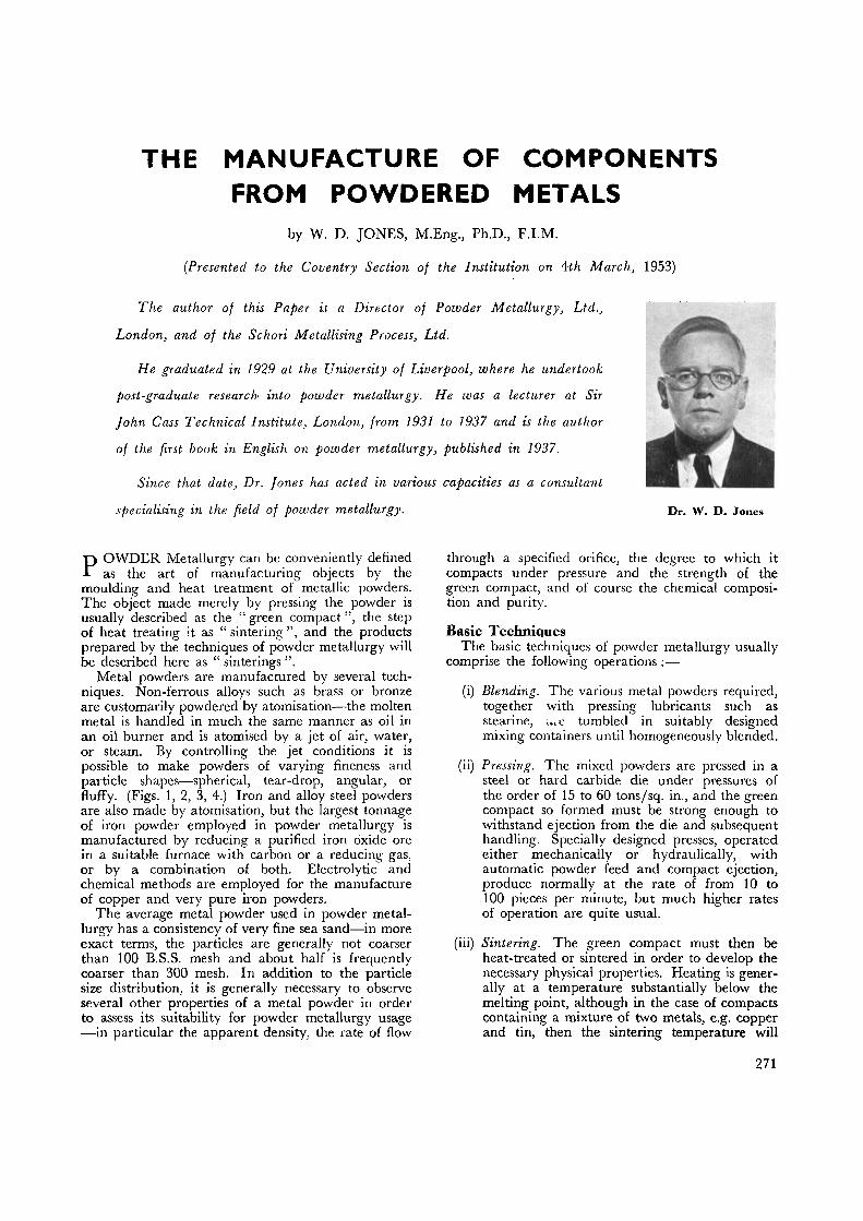
Metal powders are manufactured by several tech-niques. Non-ferrous alloys such as brass or bronzeare customarily powdered by atomisation—the moltenmetal is handled in much the same manner as oil inan oil burner and is atomised by a jet of air, water,or steam. By controlling the jet conditions it ispossible to make powders of varying fineness andparticle shapes—spherical, tear-drop, angular, orfluffy. (Figs. 1, 2, 3, 4.) Iron and alloy steel powdersare also made by atomisation, but the largest tonnageof iron powder employed in powder metallurgy ismanufactured by reducing a purified iron oxide orein a suitable furnace with carbon or a reducing gas,or by a combination of both. Electrolytic andchemical methods are employed for the manufactureof copper and very pure iron powders.
The average metal powder used in powder metal-lurgy has a consistency of very fine sea sand—in moreexact terms, the particles are generally not coarserthan 100 B.S.S. mesh and about half is frequentlycoarser than 300 mesh. In addition to the particlesize distribution, it is generally necessary to observeseveral other properties of a metal powder in orderto assess its suitability for powder metallurgy usage—in particular the apparent density, the rate of flow
through a specified orifice, the degree to which itcompacts under pressure and the strength of thegreen compact, and of course the chemical composi-tion and purity.
Basic TechniquesThe basic techniques of powder metallurgy usually
comprise the following operations:—
(i) Blending. The various metal powders required,together with pressing lubricants such asstearine, are tumbled in suitably designedmixing containers until homogeneously blended.
(ii) Pressing. The mixed powders are pressed in asteel or hard carbide die under pressures ofthe order of 15 to 60 tons/sq. in., and the greencompact so formed must be strong enough towithstand ejection from the die and subsequenthandling. Specially designed presses, operatedeither mechanically or hydraulically, withautomatic powder feed and compact ejection,produce normally at the rate of from 10 to100 pieces per minute, but much higher ratesof operation are quite usual.
(iii) Sintering. The green compact must then beheat-treated or sintered in order to develop thenecessary physical properties. Heating is gener-ally at a temperature substantially below themelting point, although in the case of compactscontaining a mixture of two metals, e.g. copperand tin, then the sintering temperature will
271
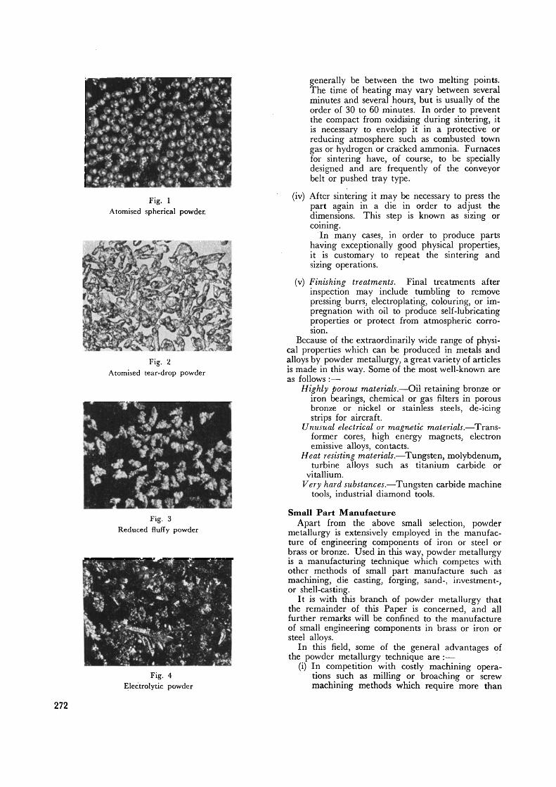
Fig. 1Atomised spherical powder.
Fig. 2Atomised tear-drop powder
Fig. 3Reduced fluffy powder
Fig. 4Electrolytic powder
generally be between the two melting points.The time of heating may vary between severalminutes and several hours, but is usually of theorder of 30 to 60 minutes. In order to preventthe compact from oxidising during sintering, itis necessary to envelop it in a protective orreducing atmosphere, such as combusted towngas or hydrogen or cracked ammonia. Furnacesfor sintering have, of course, to be speciallydesigned and are frequently of the conveyorbelt or pushed tray type.
(iv) After sintering it may be necessary to press thepart again in a die in order to adjust thedimensions. This step is known as sizing orcoining.
In many cases, in order to produce partshaving exceptionally good physical properties,it is customary to repeat the sintering andsizing operations.
(v) Finishing treatments. Final treatments afterinspection may include tumbling to removepressing burrs, electroplating, colouring, or im-pregnation with oil to produce self-lubricatingproperties or protect from atmospheric corro-sion.
Because of the extraordinarily wide range of physi-cal properties which can be produced in metals andalloys by powder metallurgy, a great variety of articlesis made in this way. Some of the most well-known areas follows: —
Highly porous materials.—Oil retaining bronze oriron bearings, chemical or gas filters in porousbronze or nickel or stainless steels, de-icingstrips for aircraft.
Unusual electrical or magnetic materials.—Trans-former cores, high energy magnets, electronemissive alloys, contacts.
Heat resisting materials.—Tungsten, molybdenum,turbine alloys such as titanium carbide or
vitallium.Very hard substances.—Tungsten carbide machine
tools, industrial diamond tools.
Small Part ManufactureApart from the above small selection, powder
metallurgy is extensively employed in the manufac-ture of engineering components of iron or steel orbrass or bronze. Used in this way, powder metallurgyis a manufacturing technique which competes withother methods of small part manufacture such asmachining, die casting, forging, sand-, investment-,or shell-casting.
It is with this branch of powder metallurgy thatthe remainder of this Paper is concerned, and allfurther remarks will be confined to the manufactureof small engineering components in brass or iron orsteel alloys.
In this field, some of the general advantages ofthe powder metallurgy technique are :—
(i) In competition with costly machining opera-tions such as milling or broaching or screw
" machining methods which require more than
272

one set-up, sinterings can frequently showvery considerable economies. This is especiallythe case where large numbers-off are involved.Broadly speaking, any machine part which canbe designed so that its manufacture is reducedto a simple pressing and sintering operation canseldom be made much more economically byany other method. This economic advantageof powder metallurgy is seen in industries en-countering very large numbers of small partsof limited ranges of design, particularly in themanufacture of clocks, calculating machines,cash registers, locks, sewing machines, casterwheels, and toys (trains, Meccano and the like).
Low production costs associated with powdermetallurgy arise from a number of facts,namely, (a) almost complete elimination ofscrap losses, (b) low direct labour charges, (c)considerably reduced stock investment in metalshapes, e.g. one metal powder instead ofnumerous assortments of extruded or rolledshapes, (d) saving in floor space, expensivemachine tools, jigs, fixtures, gauges, cuttingtools and transport, (e) reduction in inspectionand quality control costs owing to greateruniformity of product.
(ii) A wide range of physical properties is fre-quently obtainable by employing alloys oraggregates of metals which cannot be manufac-tured by melting and casting.
Low or high frictional materials or compo-nents made deliberately with low density aretypical examples.
(iii) Close dimensional tolerances are not difficultto attain and, in general, dimensional accuracycompares favourably with that of other smallparts processes. The highest standards ofaccuracy, however, demand considerable exper-ience of the process and a very close controlover rather a large number of variables withan accompanying increase in cost. Generallyaccepted commercial tolerances for brass sinter-ings are 0.004" per inch on radial dimensions,with more liberal allowances for axial dimen-sions. By sizing after sintering, tolerances ofas low as 0.002" per inch have been met on aproduction basis.
Certain DisadvantagesThere are naturally certain disadvantages asso-
ciated with powder metallurgy and the principal onesare as follows :—
(i) The raw material—the powder—costs morethan ingot metal, in general up to 50% higher,although this is not always so expensive asrolled or extruded sections. This disadvantageis frequently more than offset by the completeabsence of scrap losses.
(ii) The shape of sinterings is limited to thoseitems which can be pressed and ejected from adie, and the size is limited to the tonnagecapacity and stroke of the press. Few powdermetallurgy parts weigh more than 10 lb. and
the greatest volume of production lies probablybetween one and four ounces.
(iii) Each individual part requires a separatelydesigned die and the die cost may in somecases be high, although this may not be at allan important item if the numbers-off are con-siderable*. The high die cost, however, tends tobe discouraging in the manufacture of proto-types and a satisfactory solution to the manu-facture of a very cheap prototype die would bea great advantage.
(iv) Tool and press maintenance costs tend to behigh and it is almost impossible to undertakemanufacture by powder metallurgy without awell-equipped tool room. This disadvantage,however, applies equally well to some alterna-tive small part manufacturing techniques.
(v) Metal powders exhibit very little lateral flowin a die and show high frictional effects on thewalls of a die. These phenomena prevent themanufacture of parts with re-entrant angles, orwith wall thicknesses or variations of less than0.032", or with thicknesses very much less thanthe length. Certain of these points are broughtout in more detail in the examples shown inFigs. 5/12, which are intended to assist inexplaining the right and the wrong ways todesign sinterings. These examples are takenfrom the catalogue of the International PowderMetallurgy Company of Pennsylvania:a) Parts with multiple steps can be moulded,
but the difference between steps or offsetsmust be a minimum of .032". Wall sectionsof less than .032" increase tool maintenancecosts. (Fig. 5).
b) Chamfers or bevels of less than 30 deg.cannot be moulded; 45 deg. chamgers arepreferred. For less than 30 deg. the mould-ing punch would come to a feather edge.Such an edge will not stand up under thehigh moulding pressures required (30,000—100,000 p.s.i.) increasing die maintenancecosts. (Fig. 6).
c) Ball shaped parts, or spheres can be moulded,but a flat spot is required to prevent themoulding punches from coming together.This flat spot will be within the spherical
NOFig. 5.
YES
273

1*K\
NO YES NO YES
Fig. 6. Fig. 7.
YES
Fig. 8.
NO
section and will not interfere with a ballseat. (Fig. 7).
d) Blind end parts can be moulded. However,if a flange or any offset is opposite the blindend: one or the other must be eliminated toprovide for ejection from the die. (Fig. 8).
e) Avoid parts with abrupt and large changesin cross sectional areas. They are difficultto mould or maintain uniform densities.(Fig. 9).
f) Reentrant angles cannot be incorporated inthe die. They must be machined in sub-sequent operations. (Fig. 10).
g) Avoid parts with a minimum wall thicknessof less than .032". Dies are costly andsometimes impossible to construct and main-tenance is high. (Fig. 11).
h) Holes at right angles and external groovescannot be moulded. They can easily bemachined in subsequent operations. (Fig. 12).
Present Day ApplicationsIn order to describe more accurately the position
that powder metallurgy holds at the present day as asmall part manufacturing technique, the remainderof this Paper will deal with specific examples. Thesehave been drawn, as far as brass is concerned, from a
publication entitled " Facts about Pressed Brass",published by The New Jersey Zinc Company of NewYork.
Sheet metal stamping processes usually show lowcosts, but in the example shown in Figs. 13 and 14,the powder metallurgy technique competes with anestimated cost saving of 33%, mainly by avoidanceof scrap loss. The two parts illustrated are brasssinterings used in a Mullins dish-washer timer andmade by Merriman Bros, of Boston.
The hexagonal centre pivot hole and the six roundsatellite holes of the double acting cam are producedin the pressing operation by core rods. The twoparts illustrate the ease with which radial contoursand raised projections can be produced by powdermetallurgy. Tolerances specified for these parts wereas follows:—
Trip hole in cam
Pivot hole in lever
0.125 4- 0.001 in.— 0.000 in.
0.140 + 0.001 in.— 0.000 in.
Spring terminal hole in lever 0.125 ±- 0.002 in.Cross section of lever 0.187 ± 0.003 in.Where not specified ± 0.005 in.Coining after sintering was employed to maintain
these tolerances.Manufacture of lock parts by sintering from leaded
NO YESFig. 9.
NO YES
Fig. 10.NO YES
Fig. 11.
274
11 j IFig. 12.
brass powder is in America associated with severalimportant advantages including :—
i) Low unit costs.ii) Close tolerances.
iii) Fewer total operations.iv) Lower direct labour costs.v) Lower scrap loss.vi) Equal or superior physical properties.
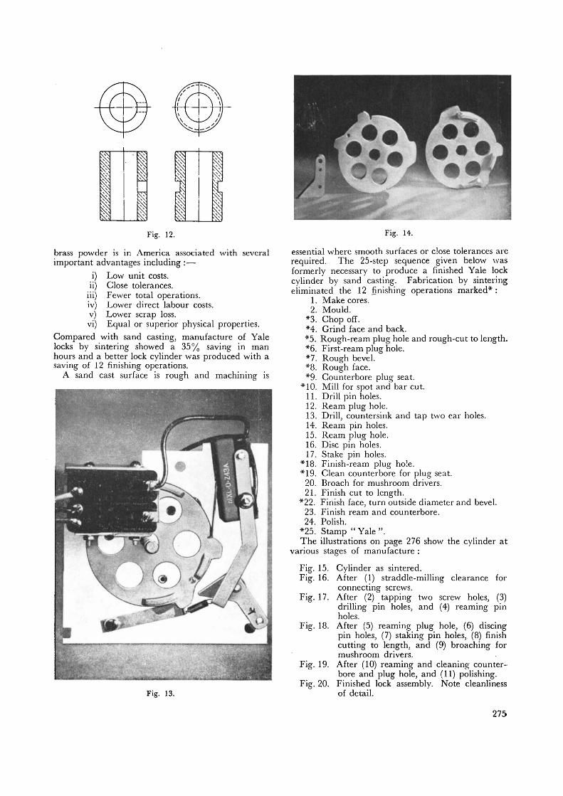
Compared with sand casting, manufacture of Yalelocks by sintering showed a 35% saving in manhours and a better lock cylinder was produced with asaving of 12 finishing operations.
A sand cast surface is rough and machining is
1.2.
*3.*4.
Fig. 13.
Fig. 14.
essential where smooth surfaces or close tolerances arerequired. The 25-step sequence given below wasformerly necessary to produce a finished Yale lockcylinder by sand casting. Fabrication by sinteringeliminated the 12 finishing operations marked*:
Make cores.Mould.Chop off.Grind face and back.
*5. Rough-ream plug hole and rough-cut to length.*6. First-ream plug hole.*7. Rough bevel.*8. Rough face.*9. Counterbore plug seat.
*10. Mill for spot and bar cut.11. Drill pin holes.12. Ream plug hole.13. Drill, countersink and tap two ear holes.14. Ream pin holes.15. Ream plug hole.16. Disc pin holes.17. Stake pin holes.
*18. Finish-ream plug hole.*19. Clean counterbore for plug seat.
20. Broach for mushroom drivers.21. Finish cut to length.
*22. Finish face, turn outside diameter and bevel.23. Finish ream and counterbore.24. Polish.
*25. Stamp " Yale ".The illustrations on page 276 show the cylinder at
various stages of manufacture :
Fig. 15. Cylinder as sintered.Fig. 16. After (1) straddle-milling clearance for
connecting screws.Fig. 17. After (2) tapping two screw holes, (3)
drilling pin holes, and (4) reaming pinholes.
Fig. 18. After (5) reaming plug hole, (6) discingpin holes, (7) staking pin holes,. (8) finishcutting to length, and (9) broaching formushroom drivers.
Fig. 19. After (10) reaming and cleaning counter-bore and plug hole, and (11) polishing.
Fig. 20. Finished lock assembly. Note cleanlinessof detail.
275

Fig. 15 Cylinder as sintered. Fig. 16. After (1), straddle-millingclearance for connecting screws.
Fig. 17. After (2), tapping two screwholes, (3) drilling pin-holes and (4)
reaming pin holes.
Fig. 18. After (5) reaming plug hole,(6) discing pin holes, (7) staking pinholes, (8) finish cutting to length and(9) broaching for mushroom drivers.
Fig. 19. After (10) reaming andcleaning counterbore and plug hole
and (11) polishing.
Fig. 20. Finished lock assembly.Note cleanliness of detail.
Cost studies made by engineers of the ContractDivision, Lewyt Corporation, show that structuralparts need not be elaborate to realise the economiesinherent in forming shapes from metal powders. Forsome shapes, raw material cost savings alone mayjustify conversion; in other design situations, re-ductions in machining costs may assume especialimportance.
The three, 48-pitch hub-gears (A) illustrated inFig. 21, formerly were fabricated at a satisfactorilyrapid production rate on a gear-cutting machine,using bar stock. However, the scrap loss was high,as metal removed in machining is waste.
For the quantities involved (above 20,000 of eachpiece) the powder metallurgy tool and die costs werenot excessively high—and finished parts could beproduced as 90-10 brass sinterings at a net 25%saving, because there is no scrap loss.
Dimensional accuracy of the gears after coining. , . . , +0.000 in.is the same as that ot machined gears —~ ^^ •—tolerance on the gear pitch, and 0.002 in. total in-dicator reading for concentricity. Mechanicalproperties for gears of this pitch are lower when
made as sinterings, but entirely satisfactory for theapplication on variable condensers.
Collars B and C are elementary shapes—whethermade by screw machine or by powder metallurgy.However, screw machine time per 100 pieces is onehalf hour for the two operations of cutting rod tolength and drilling hole. As 90-10 brass sinterings,the parts are produced well in excess of 1,000 piecesper hour—and the direct labour costs are considerablylower.
Adjustable stop D is another Lewyt part (quantityrequirements: approximately 50,000) for whichpowder metallurgy is the most advantageous method.By the former method, machining costs per 100pieces were :
1. Cutoff £hour2. End-milling ... ... 2 hours3. Counterboring ... ... £ hour4. Drill holes (3 at a time) ... \ hour
Total 3£ hours
A foot of .75-in. diam. brass rod yielded 16 pieces.
276
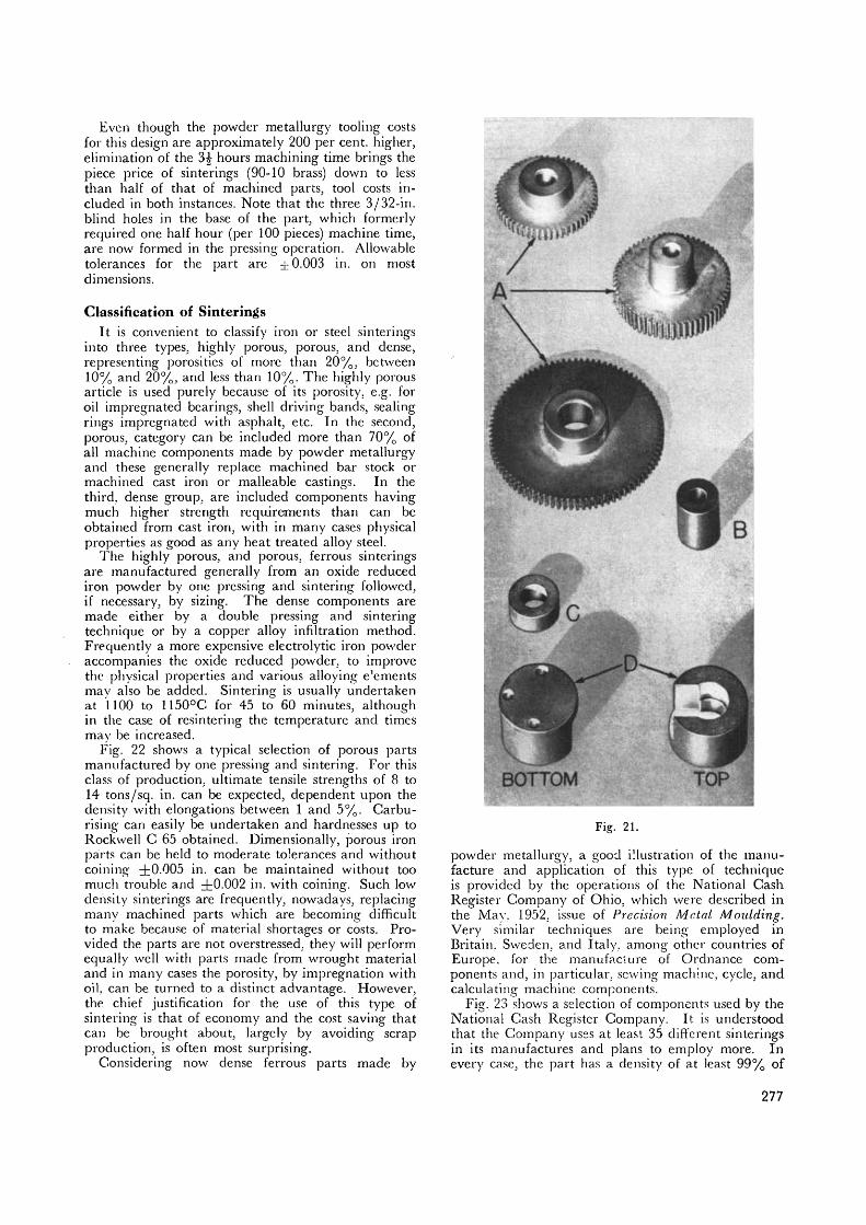
Even though the powder metallurgy tooling costsfor this design are approximately 200 per cent, higher,elimination of the 3£ hours machining time brings thepiece price of sinterings (90-10 brass) down to lessthan half of that of machined parts, tool costs in-cluded in both instances. Note that the three 3/32-in.blind holes in the base of the part, which formerlyrequired one half hour (per 100 pieces) machine time,are now formed in the pressing operation. Allowabletolerances for the part are ± 0.003 in. on mostdimensions.
Classification of SinteringsIt is convenient to classify iron or steel sinterings
into three types, highly porous, porous, and dense,representing porosities of more than 20%, between10% and 20%, and less than 10%. The highly porousarticle is used purely because of its porosity, e.g. foroil impregnated bearings, shell driving bands, sealingrings impregnated with asphalt, etc. In the second,porous, category can be included more than 70% ofall machine components made by powder metallurgyand these generally replace machined bar stock ormachined cast iron or malleable castings. In thethird, dense group, are included components havingmuch higher strength requirements than can beobtained from cast iron, with in many cases physicalproperties as good as any heat treated alloy steel.
The highly porous, and porous, ferrous sinteringsare manufactured generally from an oxide reducediron powder by one pressing and sintering followed,if necessary, by sizing. The dense components aremade either by a double pressing and sinteringtechnique or by a copper alloy infiltration method.Frequently a more expensive electrolytic iron powderaccompanies the oxide reduced powder, to improvethe physical properties and various alloying e'ementsmay also be added. Sintering is usually undertakenat 1100 to 115O°C for 45 to 60 minutes, althoughin the case of resintering the temperature and timesmay be increased.
Fig. 22 shows a typical selection of porous partsmanufactured by one pressing and sintering. For thisclass of production, ultimate tensile strengths of 8 to14 tons/sq. in. can be expected, dependent upon thedensity with elongations between 1 and 5%. Carbu-rising can easily be undertaken and hardnesses up toRockwell C 65 obtained. Dimensionally, porous ironparts can be held to moderate tolerances and withoutcoining ±0.005 in. can be maintained without toomuch trouble and ±0.002 in. with coining. Such lowdensity sinterings are frequently, nowadays, replacingmany machined parts which are becoming difficultto make because of material shortages or costs. Pro-vided the parts are not overstressed, they will performequally well with parts made from wrought materialand in many cases the porosity, by impregnation withoil. can be turned to a distinct advantage. However,the chief justification for the use of this type ofsintering is that of economy and the cost saving thatcan be brought about, largely by avoiding scrapproduction, is often most surprising.
Considering now dense ferrous parts made by
Fig. 21.
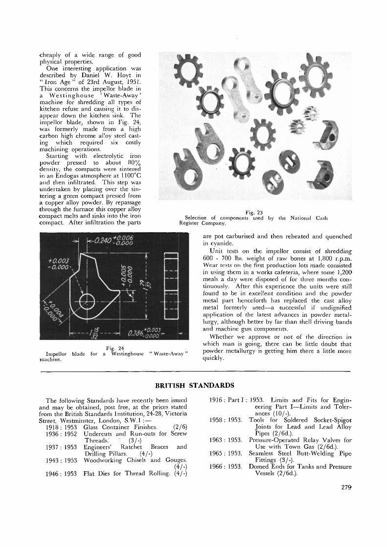
powder metallurgy, a good illustration of the manu-facture and application of this type of techniqueis provided by the operations of the National CashRegister Company of Ohio, which were described inthe May. 1952, issue of Precision Metal Moulding*Very similar techniques are being employed inBritain. Sweden, and Italy, among other countries ofEurope, for the manufacture of Ordnance com-ponents and, in particular, sewing machine, cycle, andcalculating machine components.
Fig. 23 shows a selection of components used by theNational Cash Register Company. It is understoodthat the Company uses at least 35 different sinteringsin its manufactures and plans to employ more. Inevery case, the part has a density of at least 99% of
277

theoretical and no part is employed that does nothave physical properties at least as good, if not better,than the component it replaced. The justificationin each case has been a substantial reduction in cost.In spite of the fact that an expensive electrolyticiron powder is employed, the cost of manufacture hasbeen kept low, mainly by the use of tungsten carbidedies and high carbon high chrome punches andcarbide tipped core rods. No die has ever shownany appreciable wear and one pair used for bothpressing" and coining has made over three millionpieces.
The pressing and sintering cycle employed is asfollows: —1st and 2nd Pressing : 60-65 tons/sq. in.1st and 2nd Sintering: 45-60 minutes at 1130°G inEndogas.
The final density is almost achieved after the firstsintering, and the coining and second sintering isused partly for dimensional control and partly forgrain refinement and improvement of ductility.
In the case of the manufacture of the counterpinion, powder metallurgy has replaced the opera-tions of blanking, shaving and machining, and hasreduced the number of operations from 20 to 12 andthe number of inspections from 7 to 5. The piece iscarburised to a depth of 0.015 in. and then hardened
and tempered to a final hardness of 40 Rockwell C.The one long tooth is rehardened inductively to62 Rockwell C. The impact properties of the teethare considerably improved compared with the com-ponent previously manufactured from punching stock.Normal tolerances are held to ±0.001 in. and onlyoccasional spot checks are made, instead of routineinspection of 25 to 100% of the pieces when madeby machining.
A New TechniqueInfiltration with a copper alloy is a new technique
which is being increasingly employed for theeconomical manufacture of high density high tensilecomponents by powder metallurgy. In this case thepressing step is undertaken with comparatively lowpressures, thus permitting long life of cheaper diesets and the relatively porous part after sintering hasthe pores filled up with a molten copper alloy—forexample, an alloy of copper with 5% of manganeseand 5% of iron. The added alloy does more thanjust fill up the porosity, for a certain amount ofalloying with the iron occurs and surprising improve-ments in physical properties can be achieved, rangingfrom a 20 ton tensile with 20-30% elongation to 45ton tensile with 1 to 4% elongation. The infiltrationtechnique thus permits the production comparatively
Fig. 22. Typical selection of porous parts manufactured by one pressing and sintering.
278
cheaply of a wide range of goodphysical properties.
One interesting application wasdescribed by Daniel W. Hoyt in"Iron Age" of 23rd August, 1951.This concerns the impellor blade ina Westinghouse 'Waste-Away'machine for shredding all types ofkitchen refuse and causing it to dis-appear down the kitchen sink. Theimpellor blade, shown in Fig. 24.was formerly made from a highcarbon high chrome alloy steel cast-ing which required six costlymachining operations.
Starting with electrolytic ironpowder pressed to about 80%density, the compacts were sinteredin an Endogas atmosphere at 1100°Cand then infiltrated. This step wasundertaken by placing over the sin-tering a green compact pressed froma copper alloy powder. By repassagethrough the furnace this copper alloycompact melts and sinks into the ironcompact. After infiltration the parts
+0.003-O.OOO*
^3 I
r+0.003
Fig. 24Impellor blade for a Westinghouse
machine.Waste-Away "
Fig. 23Selection of components used by the National Cash
Register Company.
are pot carburised and then reheated and quenchedin cyanide.
Unit tests on the impellor consist of shredding600 - 700 lbs. weight of raw bones at 1,800 r.p.m.Wear tests on the first production lots made consistedin using them in a works cafeteria, where some 1,200meals a day were disposed of for three months con-tinuously. After this experience the units were stillfound to be in excellent condition and the powdermetal part henceforth has replaced the cast alloymetal formerly used—a successful if undignifiedapplication of the latest advances in powder metal-lurgy, although better by far than shell driving bandsand machine gun components.
Whether we approve or not of the direction inwhich man is going, there can be little doubt thatpowder metallurgy is getting him there a little morequickly.
BRITISH STANDARDS
The following Standards have recently been issuedand may be obtained, post free, at the prices statedfrom the British Standards Institution, 24-28, VictoriaStreet. Westminster, London, S.W.I :—
1918 : 1953 Glass Container Finishes. (2/6)1936 : 1952 Undercuts and Run-outs for Screw
Threads.' ' (3/-)1937 : 1953 Engineers' Ratchet Braces and
Drilling Pillars. (4/-)1943 : 1953 Woodworking Chisels and Gouges.
(4/-)1946 : 1953 Flat Dies for Thread Rolling. (4/-)
1916 : Part I : 1953. Limits and Fits for Engin-eering Part I—Limits and Toler-ances (10/-).
1958: 1953. Tools for Soldered Socket-SpigotJoints for Lead and Lead AlloyPipes (2/6d.).
1963 : 1953. Pressure-Operated Relay Valves forUse with Town Gas (2/6d.).
1965 : 1953. Seamless Steel Butt-Welding PipeFittings (3/-).
1966 : 1953. Domed Ends for Tanks and PressureVessels (2/6d.).
279


![NATURE OF METALS AND ALLOYS - New Jersey Institute of ...1]-Fall2017.pdfCeramics • A ceramic is “an inorganic, nonmetallic solid that is prepared from powdered materials and is](https://img.pdfslide.us/doc/110x75/5e7af29d532b087ffc4aafca/nature-of-metals-and-alloys-new-jersey-institute-of-1-ceramics-a-a-ceramic.jpg)