Embed Size (px)
Citation preview
The Making Of A Legend- The Niagara Story Thomas R. Get:bracht
Part I Introduction
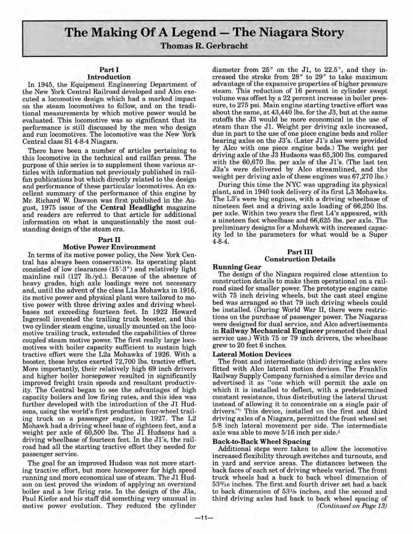
In 1945, the Equipment Engineering Department of the New York Central Railroad developed and Alco executed a locomotive design which had a marked impact on the steam locomotives to follow, and on the traditional measurements by which motive power would be evaluated. This locomotive was so significant that its performance is still discussed by the men who design and run locomotives. The locomotive was the New York Central class S1 4-8-4 Niagara.
There have been a number of articles pertaining to this locomotive in the technical and railfan press. The purpose of this series is to supplement these various articles with information not previously published in railfan publications but which directly related to the design and performance of these particular locomotives. An excellent summary of the performance of this engine by Mr. Richard W. Dawson was first published in the August, 1975 issue of the Central Headlight magazine and readers are referred to that article for additional information on what is unquestionably the most outstanding design of the steam era.
Part II Motive Power Environment
In terms of its motive power policy, the New York Central has always been conservative. Its operating plant consisted of low clearances (15'-3") and relatively light mainline rail (127 lb./yd.). Because of the absence of heavy grades, high axle loadings were not necessary and, until the advent of the class L1a Mohawks in 1916, its motive power and physical plant were tailored to motive power with three driving axles and driving wheelbases not exceeding fourteen feet. In 1922 Howard Ingersoll invented the trailing truck booster, and this two cylinder steam engine, usually mounted on the locomotive trailing truck, extended the capabilities of three coupled steam motive power. The first really large locomotives with boiler capacity sufficient to sustain high tractive effort were the L2a Mohawks of 1926. With a booster, these brutes exerted 72,700 lbs. tractive effort. More importantly, their relatively high 69 inch drivers and higher boiler horsepower resulted in significantly improved freight train speeds and resultant productivity. The Central began to see the advantages of high capacity boilers and low firing rates, and this idea was further developed with the introduction of the J1 Hudsons, using the world's first production four-wheel trailing truck on a passenger engine, in 1927. The L2 Mohawk had a driving wheel base of eighteen feet, and a weight per axle of 60,500 lbs. The J1 Hudsons had a driving wheelbase of fourteen feet . In the J1's, the railroad had all the starting tractive effort they needed for passenger service.
The goal for an improved Hudson was not more starting tractive effort, but more horsepower for high speed running and more economical use of steam. The J1 Hudson on test proved the wisdom of applying an oversized boiler and a low firing rate. In the design of the J3a, Paul Kiefer and his staff did something very unusual in motive power evolution. They reduced the cylinder
diameter from 25" on the J1, to 22.5", and they increased the stroke from 28" to 29" to take maximum advantage of the expansive properties of higher pressure steam. This reduction of 16 percent in cylinder swept volume was offset by a 22 percent increase in boiler pressure, to 275 psi. Main engine starting tractive effort was about the same, at 43,440 lbs. for the J3, but at the same cutoffs the J3 would be more economical in the use of steam than the Jl. Weight per driving axle increased, due in part to the use of one piece engine beds and roller bearing axles on the J3's. (Later J1 's also were provided by Alco with one piece engine beds.) The weight per driving axle of the J3 Hudsons was 65,300 lbs. compared with the 60,670 lbs. per axle of the J1's. (The last ten J3a's were delivered by Alco streamlined, and the weight per driving axle of these engines was 67,270 lbs.)
During this time the NYC was upgrading its physical plant, and in 1940 took delivery of its first L3 Mohawks. The L3's were big engines, with a driving wheelbase of nineteen feet and a driving axle loading of 66,250 lbs. per axle. Within two years the first L4's appeared, with a nineteen foot wheelbase and 66,625 lbs. per axle. The preliminary designs for a Mohawk with increased capacity led to the parameters for what would be a Super 4-8-4.
Part III Construction Details
Running Gear The design of the Niagara required close attention to
construction details to make them operational on a railroad sized for smaller power. The prototype engine came with 75 inch driving wheels, but the cast steel engine bed was arranged so that 79 inch driving wheels could be installed. (During World War II, there were restrictions on the purchase of passenger power. The Niagaras were designed for dual service, and Alco advertisements in Railway Mechanical Engineer promoted their dual service use.) With 75 or 79 inch drivers, the wheelbase grew to 20 feet 6 inches. Lateral Motion Devices
The front and intermediate (third) driving axles were fitted with Alco lateral motion devices. The Franklin Railway Supply Company furnished a similar device and advertised it as "one which will permit the axle on which it is installed to deflect, with a predetermined constant resistance, thus distributing the lateral thrust instead of allowing it to concentrate on a single pair of drivers:' 1 This device, installed on the first and third driving axles of a Niagara, permitted the front wheel set 5/8 inch lateral movement per side. The intermediate axle was able to move 5/16 inch per side. 2
Back-to-Back Wheel Spacing Additional steps were taken to allow the locomotive
increased flexibility through switches and turnouts, and in yard and service areas. The distances between the back faces of each set of driving wheels varied. The front truck wheels had a back to back wheel dimension of 533/16 inches. The first and fourth driver set had a back to back dimension of 531/s inches, and the second and third driving axles had back to back wheel spacing of
(Continued on Page 13)
-11-
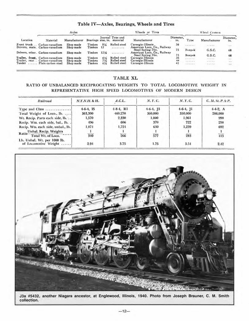
Table IV-Axles, Bearings, Wheels and Tires
\\"heels or Tires
l ...oc-ation )laterial Manufacturer Journal Type and
Bearings size, in. ma terial Manufacturer Diameter,
in. Type Manufacturer Diameter.
in.
Front truck .. Carhon-Yanadium Shop made Dri\'ers, main . Carl>on-vanadium Shop made
Drivers, other. Carbon-vanadium Shop made
Trailer, front. Carbon·\·anadium Shop made Trailer, rear . . CariJon-vanadium Shop made Tender . ····· Plain carbon steel Shop made
Tim ken 8~ Rolled s teel Carnegie-Illinois 36 Timken 13 American Loco. Co., Railway
Steel Sr.-ring Div. 75 Jloxpok G.S .C. Timken 12!.1 American Loco. Co. , Railway
Steel Spring Div. 75 Boxpok G.S.C. Tim ken 6Y, Rolled steel Carnegie-Illinois 36 Tim ken 7Y, Rolled steel Carnegie-Illinois 44 Timken 6Y, Rolled stee l Carnegie-Illinois 41
TABLE XL
RATIO OF UNBALANCED RECIPROCATING WEIGHTS TO TOTAL LOCO!\IOTIVE WEIGHT IN REPRESENTATIVE HIGH SPEED LOCOMOTIVES OF MODERN DESIGN
68
68
!:ail road N.Y.N.ll. & H. I A .C.L. I N. l'. C N . Y.C. C. :\1 . St.J>. & J>.
"ype and Class '1 '1
\
R R
••• •• • •• 0 • •• • • •
··otal Weight of Loco., lb. Vt. Recip. Pans each side, lb. ·, . ccip. Wts. each sid~. hal., lb. c::dp. \\Its. each side, unbal., lh ,
R . Unhal. Recip. Weights
allo - -Total Wt. o(Loco. • • • • ·
.h. lJnbal. Wt. per 1000 lb. of Lo<:umotivc \Veight ......
4-6··1, 15 4 -8-4, Rl 363,300 ·160,270
1,570 2,330 -196 606
I .o71 1,72-t I 1
340 - ---266
2.91 3.75
-4-6··1. J3 -1 -6-4, Jl 4-4-2, A 360,000 350,000 286,000
1,000 1,961 990 370 722 298 6:>0 1,239 692
I 1 I -
577 283 ·113
1.75 3.:i·l I 2.-12
J3a #5432, another Niagara ancestor, at Englewood, Illinois, 1940. Photo from Joseph Brauner, C. M. Smith collection.
-12-
-
531/4 inches. The back to back dimension of the trailing truck wheels had a 533/s dimension.3 (On a J3a Hudson, the front truck and the trailing truck wheel dimensions were the same as the Niagaras, but all three driving axles of the J3a's were at 531/4 inches.) One-eighth of an inch may not seem like much, but this and the use of lateral motion devices probably meant the difference between being on the rails and being on the ties, on a physical plant which had not quite caught up to its largest motive power. Axles, Bearings, Wheels and Tires
The Niagaras were designed for high utilization, and no detail was overlooked in the quest for more time on the road. Table IV summarizes the physical dimensions of the running gear of S1a Number 6000. Railroads in the steam era were not specifically concerned with interchangeability of non-wearing parts; note the five different axle diameters specified for the engine and tender of a Niagara. Because of the projected power output and in the interest of long life, main driver journals were 13 inches in diameter, and the other three driver sets used 121/s inch roller bearing journals. Each driving axle was hollow bored and used Timken split housing double roller bearings.4
Main and Side Rod Design and Arrangement The relatively small cylinders (22.5 inches on the J3a
and 25.5 inches on the S1b's) kept reciprocating weights low and this, combined with the application of a complete set of tandem roller bearing rods, resulted in running gear with very high speed capability. The selection of lightweight rods was the result of very favorable experience with a Timken rod set on J1e Hudson number 5344 in 1936. The following Table compares the rod weights between a plain bearing and the Timken assembly for a J1 Hudson which appeared in the 1938 Locomotive Cyclopedia.5
COMPARISON Of ROO WEIGHTS,LBS.
SIDE RODS MAIN ROO
PLAIN BR C. . TIMKEN PLAIN BAG. TIMKE.N
WT. O N MAIN PIN 556 338 581 319
WT. ON F'RONT PIN 190 150
WT. ON REAR PIN 176 150
WT. ON X- HEAD PIN 422 2 10
TOTAL 92 2 636 1003 ,.
PLAIN SEARING MAIN ROO
ECCENTRJCI.T.Y & WITH TIM KEN RODS
TIMKEN MAIN ROD
Counterbalance and Crossbalance In order to completely balance a set of side rods,
weight, usually lead, had to be added to each wheel opposite the location of the rods themselves. In addition, the piston, the piston rod, the crosshead assembly, the union link and bushing, and one end of the main rod did not revolve, but reciprocated. This mass, which moved back and forth, also had to be balanced. The only possible location for this balance was also in the driving wheel counterweights. In this location it could not completely balance the reciprocating mass so some unbalance remained. For some time locomotives design engineers had known that the mass of the rod and piston assembly also affected the wheel on the opposite side of the locomotive. The British devised a method to calculate and balance for the effect of "couples" in the early 1930's. This "crossbalance" was adopted by Paul Kiefer for all passenger power after 1936, and all Hudsons had their main driver set crossbalanced as they were
shopped.6 The result of this additional weight, over that required to balance the rod assembly was appropriately called "overbalance:' A Railway Mechanical Engineer editorial dated October 1945 summarizes the differences in counterbalance in the J3 Hudsons, L4 Mohawks, and the 81 Niagaras as follows:
"In the matter of counterbalance, however, none of the three locomotives are alike. While the reciprocating parts of the L4 and the S1a are approximately the same, the overbalance on the S1a has been brought down to 387 lbs. - 97 lbs. per wheel. For the L4 and J3 locomotives, respectively, the overbalance is 543 lbs. and 493 lbs. which is equivalent to about 136 and 164 lbs. per driving wheel, respectively. The weight of the unbalanced reciprocating parts per ton of locomotive is 3.34 for the J3 locomotive and about 5 lb. for each of the two eight-coupled locomotives:'7
In particular, the J3a Hudsons may have been the most well balanced reciprocating steam locomotives ever. Ralph Johnson of Baldwin in his book The Steam Locomotive, included a table comparing unbalanced reciprocating weights for several different high speed passenger locomotives.8 Table XL speaks for itself, another testament to the Kiefer genius.
Any imbalance in the revolving and reciprocating parts of the running gear of a steam locomotive resulted in rail pound, known as dynamic augment, with serious effects on track and roadbed. Timken Roller Bearing Rods
Timken addressed this problem in the 1930's. Figure 7, reproduced from a Timken entry in the 1938 Loco Cyclopedia, shows dynamic augment curves for main driving wheels of several different locomotives.9 Included in the chart was the J1e with plain bearing rods and with Timken roller bearing rods. Several J1 contemporaries were also included, including the PRR K4s. A NYC J1e Hudson equipped with plain bearing rods had the same dynamic augment at 104 miles per hour that the Pennsy K4 had at 86 mph, and a J1e with roller bearing rods had the same dynamic augment at 130 mph that a plain bearing PRR K4s had at 80 mph. In terms of smooth high speed potential, there was never any real comparison between the two locomotives.
This forward thinking was adopted for the running gear of the Niagaras, but the calculated piston thrusts of up to 160,000 lbs. per side and a concern over axle bending stresses as well as main crank pin loading resulted in the application of a tandem rod arrangement to the main and intermediate rod pins. Starting from a position on the main pin and nearest the wheel, a single rod leads from the main to the front driving wheel; in order, outside of this on the main pin, are a main to intermediate side rod, the main rod back end, and another main to intermediate. The rod to the fourth driver is installed between the two main to intermediate rods on the third driver. The rods had spun brass liners which were slipped over the outside bearing races. The reciprocating parts and crank pins, with the exception of the front, are chrome-nickel-molybdenum steel. The main and side rods are manganese-vanadium, and the locomotive axle's carbon-vanadium steel. The crank pins in the front drivers are of carbon steel.10
The piston rods were hollow and made of Timken alloy steel. The crosshead connection was by Timken, with an aluminum crosshead shoe. The valve guides were not connected to the cylinders, but to the frame.
(Continued on Page 15)
-13-

L3a #3008, yet another Niagara ancestor, at White Pigeon, Michigan, March 25, 1952. Photo by L. G. Isaac.
I J
L4a #311 0, an immediate Niagara ancestor, at Buffalo Central Terminal, March 28, 1952. Photo by Joseph Brauner, C. M. Smith collection.
-14-

UP. r-13 ~LAIN1 BRC., -'
30
C.B.~Q. S~4 P~AIN ~RG.j / ::.i.; I I~ I Qj
~ ~·-/ /J; Qj
~~-/ /~;/ ~ Q.-..J
; I ~ t~-r--.::. II' 0'
.;, 1 I l /-;.. Ill
...J I I I 4>1 t 0 i I IQ ' q_V'r. z <(
)'/ 1/ ~~ (/) :::> 0
/)' /~ / ~r; ~-tc~ :t 1-
z
25
20
15 1-z IV/~~ I I I / ~~ ~ ~~~0· I>J ::!: It / q_<?c· ~~t-:'<-~ ~ II I.// / ~-,-<-~~ ~<:> · :::> <(
/ ij v ~~~~~ 10 0· ~ l/ V/ // v0~· ~,~~'<-~ ::!: <(
b~ / ~\''<-~,~·.-z
I v~ ~ ~:< ·\~"'-"' >-0
_,:;: 1~/ ~ ~~v l\.c~~ v-,. & ~_; ~ ~ SPEED IN MILES JER HOUR ~,::.-:::;... -0 10 20 30 40 50 60 70 80 GO 100 110 120 130
Fig. 7-Dynamic augment curves for main drivers of locomotives. These curves show the reduced dynamic augment obtained by using Timken Bearing rotating and reciprocating parts rather than the plain bearing parts in use on the roads mentioned
The design approach involving smaller cylinders with 14 inch piston valves and Baker-Pilliod long travel 8112 inch valve gear permitted the use of comparatively small balance weights. The total revolving weights on each side of the locomotive· amount to 3064lbs., and the reciprocating weights to 154 7 lbs. of which 22.3 percent was cross balanced.11 The result was a design which would permit running speeds well in excess of 100 mph if desirable, with low maintenance costs and economical use of steam. A significant feature of the Timken rod assembly was the deep !-beam type upper and lower rod flanges which are not apparent in photographs, and is reproduced below for a Hudson application.12
Boiler-Overview The real secret of the performance of a steam locomo
tive was its boiler, and in this respect the Kiefer ratios and proportions resulted in a boiler which probably had the highest evaporative capacity of any two cylinder lo-
Fig. 8-light-weight locomotive main and side rods of Timken design and made from Timken High Dynamic Steel
comotive ever built. The shell courses of the boiler were of carbon-silicon steel, which permitted a weight reduction of about 7000 lbs. compared with carbon steel. 13
(This would indicate that total engine weight of the Niagaras which received new boiler shells increased from 471,000 to 478,000 lbs. as the boiler shells were replaced.) The choice of boiler material may have been made as the result of favorable experience with carbonsilicon boilers on three J1e Hudsons in 1931, including the 5343 and the 5344, which were also test beds for roller bearing journals. 14 The inside of the firebox was welded. The boiler was fed by a Worthington 7SA feedwater heater on the left side and a Nathan No. 4000 injector on the right side.15 The Worthington heater had a capacity of 270 gallons per minute or 135,000 lbs. per hour/6 a necessity for a boiler design target of 125,000 lbs. of steam per hour. Railway Mechanical Engineer analyzed the boiler evaporative capacities of the latest NYC locomotives in October, 1945:
"The class S1a estimated boiler performance exceeds that of both the other two locomotives. These each have approximately the same ratio of firebox heating surface to total evaporative heating surface (0.086 for the J3 class and 0.080 for the L4 class.) The total evaporation of the Class J3a was 96,000 lbs. and the class L4 103,000 lbs. Thus each developed a fraction over 22 lbs. of evaporation per square foot of evaporative heating surface. The new boiler is expected to evaporate up to 125,000 lbs. and if it does, it will be at the rate of 27 lbs. per square foot of evaporative heating surface. This expectation is, no doubt, based largely on the change in ratio of firebox heating surface to total evaporative heating surface, which has been increased to 0.112. There is little variation in weight efficiency among the three types. The pounds of engine weight per indicated horsepower are, respectively, 76.2 for the Class J3, 72.5 for the Class L4, and 78.5 for the Class S1a."17
The Niagara had the highest ratio of direct heating surface to total evaporative heating surface of any two cylinder single expansion locomotive in the world. 18
A) Boiler Test Results The boiler of a 6000 compared favorably with many
much larger engines in terms of evaporative capacity, including articulateds. In October, 1946, S1a number 6000 was tested on the stationary test plant at Selkirk, New York. During these tests, a maximum evaporation rate of 157,000 lbs. of steam per hour19 was generated, corresponding to 8050 boiler horsepower. In his book, The Steam Locomotive in America, Alfred Bruce reproduced a boiler evaporation curve "for a modern 4-8-4
(Continued on Page 17)
Photo -1938 Locomotive Cyclopedia
-15-
.,...... ~-'. •' t _,.,.
:~ :..,~., , "' ;,
1 ~l.r I<;!! L...l..
7 support
or steel
----- -----16'23r,"-----------
~Boiler
4"xfAngle 6 long
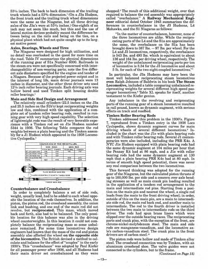
Drypipe Installation on New York Central 4-8-4 Type Locomotives, Classes S-la, S-lb and S-2a, with domeless boilers.
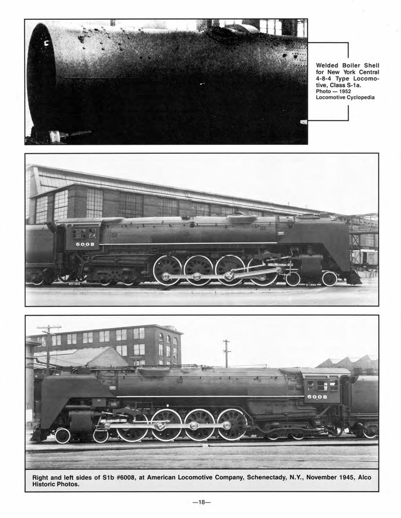
Right and left sides of S1b #6008, at American Locomotive Company, Schenectady, N.Y., November 1945, Alco Historic Photos.
-16-
type locomotive" with a test date of October, 1946, which show a boiler evaporation rate of 126,000 lbs.20
B) Steam and Exhaust Passages There w_ere several reasons for the high evaporation
rate. The most obvious is the ratio of direct to total evaporative heating surface. Also, the boiler was designed with extra large steam and exhaust passages to reduce pressure drop in the cylinders.21 This reduced back pressure would increase boiler efficiency and drawbar horsepower. The following chart22 compares the size of the steam passages for the Niagara and for the J3 Hudson and the L4 Mohawk:
Table III- Steam Passage Areas (Sq. In.) New York Central Class S-la 4-8-4 'IYPe Locomotive
Internal area of dry pipes ...... . .. . ..... . . . .. .. .. . Area of dry-pipe slots . ........... . ..... .... ... .. . Minimum area through superheater tubes ... ..... ... . Area past throttle valves, wide open .... . .. ........ . Internal area of one steam pipe . . .. .... ... . .. .. ... . Port area one valve bushing at 50 per cent cut-off .... . Minimum area of passage, one end of cylinder to
valve bushing . ........... . ..... .. . .. ......... . Port area of one valve bushing .. .... ... ...... .. ... . Exhaust port area of one valve bushing at end of
piston stroke . ............. ... .. .. ..... .... ... . Available exhaust area around valve bushing, end of
piston stroke ......... . . .. ......... ...... . .... . Exhaust area at end of v.alve bushing .... . .. .... .. .. . Exhaust area one side of exhaust stand ... ..... . .... . Area exhaust nozzle ... . ... . ... .. . . .... . . .. . . . . .. . Area one cylinder . ......... .. ... ......... .... .. . .
L-3 J-3 L-4 S-la
56.7 69.0 95.0 140.0
61.8 70.5 86.6 59.5 73.6 98. 4 50.2 56. 7 63 .6 30.1 29.2 30. 5
42. 9 51.8 53.2 76 .3 79.6 90. 4
70.0 69.3 70 .9
50.0 56.0 57.0 76.0 73.1 75 .0 52.0 52.0 62.0 38.5 39.9 44 .2
397.6 530.9 490.9
The most obvious restriction to the steam flow is the port area of one valve bushing of 30.5 square inches at 50 percent cutoff. The poppet valve system of S2a number 5500 was designed to correct this deficiency, as we will see when we analyze Niagara road tests in a later section.
The boiler was as high and wide as NYC clearances would permit. The outside diameter of the third course is 100 inches, and the top of the boiler was practically at the clearance limit, which precludes the employment of a steam dome. In lieu of a steam dome, from which to collect steam, the steam dry pipe, closed at the rear end, has a series of 28 one inch traverse slots across the top, each with a clear chord length of five inches. The dry pipe, eleven inches in inside diameter, has an internal cross-sectional area of95 square inches. The steam gathering area through the 28 1 inch by 5 inch slots is 140 square inches.23 The (opposite) diagram of the slotted dry pipe is reproduced from the 1952 Locomotive Cyclopedia. 24
The outside diameter of the bare boiler of 100 inches did not include boiler lagging of approximately 21/2
inches thickness per side. (Boiler lagging was available in thicknesses of one to four inches in 1/8 inch increments.)25 The boiler sheathing of approximately 118 inch thickness must also be added to obtain the in-service boiler diameter. A good model of a NYC Niagara would have a third course in-service boiler dimension of approximately 105 inches.
C) Superheater and Superheater Proportions Although the boiler of a Niagara could be described as
a firebox-direct heat transfer design as opposed to a tube-and-flue heat transfer design, special attention was
given to the installation of a large capacity superheater with extra large steam passages to provide the high degree of superheat required for maximum boiler efficiency and maximum drawbar horsepower. The size of the superheater itself in terms of superheating surface, is governed by the type of superheater (Type A or Type E) and the length of the firetubes in which the superheater is installed. The Niagaras used a Type E superheater which was superior to the Type A in yielding a higher degree of superheat at low and moderate boiler firing rates. An Elesco advertisement in the 1938 Locomotive Cyclopedia described the function of superheaters as well as a summary of performance of Type A and Type E superheaters as follows:
"Superheated steam can be defined simply as steam having a higher temperature than that corresponding to its pressure. The temperature difference between superheated steam and saturated steam at the same pressure is known as the degree of superheat .. . The use of a high degree of superheat on locomotives produces marked economies in fuel and in water for the same output of power. Furthermore, there is a considerable increase in hauling capacity ofthe locomotive.
Type A superheaters met requirements for many years, but as conditions demanded higher sustained capacity coupled with the necessity offurther increasing the efficiency of steam locomotives, it was realized that further encroachment upon flue evaporating surfaces would be a detriment, and yet higher superheat was demanded. The Type "E" superheater provided the solution. This superheater absorbs a much greater percentage of heat in the flue gases than the Type ".N' with the result that, at a lower combustion rate on the grates, steam temperatures equivalent to what are had with the Type ".N' superheater are obtained. On the other hand, with the same combustion rate, substantially higher steam temperature and resultant lower steam consumption per unit of power developed, are achieved. The result is that regardless of locomotive size or class of service contemplated, the Type "E" equipment will definitely increase the boiler efficiency and is, therefore, recommended."26
In over-the-road testing, Niagara 6023 demonstrated superheat temperatures of 762 degrees/ 7 among the highest ever recorded for single expansion locomotives.
The design change in the tube length from the nineteen foot tubes of No. 6000 to the 19-111/4 tube length of the production engines Nos. 6001-6025 has been repeated elsewhere. This change in tube length also resulted in an increase in the superheating surface from 1977 to 2073 square feet. The superheating surface increase corresponds exactly with the ratio of the increase in tube length. From this we may infer that no dimensional change in the superheater was made except for the length increase necessary to expose the steam in the superheater to the hotter firebox gasses within the longer firetubes.
D) Smokebox Arrangement The front end drafting arrangement on the Niagaras
was based on the success of the NYC Selkirk tests conducted in 1940 and 1942 and reviewed in the Fourth Quarter 1983 issue of the Central Headlight. This test confirmed that changes in the draft arrangement could increase boiler evaporation up to 11.7 percent on J1loco-
(Continued on Page 19)
-17-
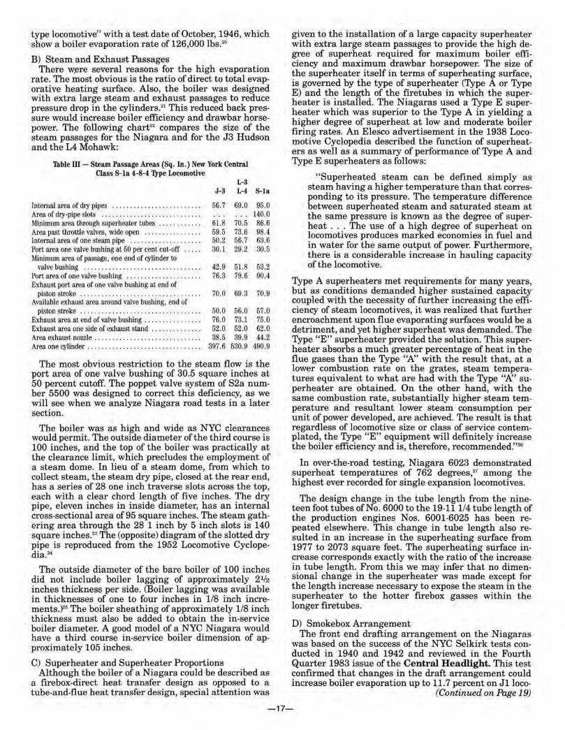
Welded Boiler Shell for New York Central 4-8-4 Type Locomotive, Class S-1a. Photo -1952 Locomotive Cyclopedia
Right and left sides of 51 b #6008, at American Locomotive Company, Schenectady, N.Y., November 1945, Alco Historic Photos.
-18-
motives. In the test, hourly evaporation was increased from 77,000 lbs. of steam per hour to 86,000 lbs. per hour at a coal firing rate increase from 12,300 lbs. per hour to 14,000 lbs. per hour. On a J3 for which preliminary results were reported, evaporation increased from 84,000 lbs. per hour to 93,000 lbs. per hour, and the evaporation curve had not yet peaked.28 To place this Hudson boiler performance in perspective, Ralph Johnson of Baldwin reported an hourly boiler evaporation rate for a PRR 4-4-4-4 Class T1 at 105,475 lbs.29 In an article in Railway Mechanical Engineer dated October, 1945, the total evaporation of the Class J3 was 96,000 lbs. and the Class L4 was 103,000 lbs.30 The changes to the Selkirk front end arrangement were internal, involving an increase in the exhaust nozzle diameter from 63/4 to 7 inches, on Hudsons, and a cutout from the diaphragm near the smokebox shell to reduce the number of right angle bends the bottom flue gases would take to get to the stack, from five bends and 450 degrees in turning to two bends and 90 degrees.31 The Niagaras were equipped with a 71/z inch by 711!16 inch diameter exhaust nozzle and a 23 inch diameter stack which protruded seven inches above the smoke box. 32
Mention has been made in other articles about adapting the Niagaras for a "KYLCHAP" exhaust system and a twin stack.33 There is no indication that this exhaust arrangement would have provided any increase in boiler or drawbar horsepower, or increased cost effectiveness, over the Selkirk front end arrangement with which these locomotives were equipped. All indications were that the principle restriction in the live steam and exhaust circuit was at the piston valve itself. The smokebox itself contained the superheater header, including the front end throttle, and had an inside diameter of 90 inches and a sheet thickness of3/4 inches. It was uninsulated. The smoke box was welded to the first ring of the boiler. The first ring had a bare non-lagged diameter of 961/s inches.34
E) Steam Pressure The boiler of the Niagaras had been designed for a
working pressure of 290 pounds per square inch with a safety factor of 4.5.35 At that time, ICC rules required a minimum factor of safety of 4.0. The factor of safety was established as a safeguard against hidden flaws and in variations in the fabrication and assembly of the boiler itself. While the original Niagara was set at 275 psi at delivery, it probably operated at 290 psi after its 79 inch drivers were installed in July, 1945. The production engines 6001-25 were set at 275 psi at delivery. Locomotives having 300 psi had been shipped to the Santa Fe as early as 1938, and in the history of steam both Kansas City Southern and Santa Fe had 2-10-4's with steam at 310 psi. Paul Kiefer may have had access to boiler maintenance cost data which the author has been unable to uncover. The belief is that NYC chose to restrict steam pressures to a reasonable level in the interests of low boiler maintenance costs and maximum locomotive availability. This resulted in a maximum of 275 psi for the S1b's and 265 psi for the J3's. ~tis interesting to note that Kiefer chose to increase cylinder diameter from 25 inches to 25.5 inches on the production Niagaras to maintain starting tractive force, rather than resetting the pressure to 290 psi. The change to increase cylinder diameter probably involved a core change to the one piece GSC cast engine bed. This was a major design change. A change from 275 to 290 psi would have only involved resetting the "pops" with a wrench. Kiefer must have highly valued lower boiler pressure and its
resultant lower maintenance cost, as long as boiler efficiency and drawbar horsepower were not seriously compromised. In a later section we will review the tractive effort and drawbar horsepower performance which supports the wisdom of the Kiefer decision. F) Welded Boilers
In retrospect, the choice of silicon-carbon for boiler shell material was the wrong decision. Some time after they entered service, transcrystalline cracking of the boiler shells occurred and some, and possibly all, boilers were replaced by Alco.36 Additionally, at least S1a No. 6000 may have been retrofitted with an all-welded boiler. The 1952 Loco Cyclopedia published a photo of a completely welded boiler shell "for an S1a Niagara".38
If this shell was applied to No. 6000, it may explain why this engine was one of the last to be retired.
In the 1940's, Alco was still committed to steam, and had installed a large annealing furnace to stress relieve all-welded boilers. The furnace could accept boilers as long as those used on 4-6-6-4 Challenger Mallets. Alco had refitted all-welded boilers to several locomotives. A 1951 edition of Trains & Travel referred to the application of welded boilers to 36 locomotives on six different railroads, including one on a NYC Hudson. The article went on to say that "Central plans to install welded boiler shells on all of its 27 Niagara 4-8-4's and 40 Hudsons:'39 Based on the date of this entry and on the retirement of Kiefer in March, 1953,40 there is serious question that few, if any, Niagaras received welded boiler shells. There are records to indicate that most, if not all, of the Niagaras had their original boiler shells replaced with boiler courses of plain carbon steel, however.
Tender Details The lineage of the pedestal bed fourteen-wheel tender
can be traced directly to the Union Pacific design of 1939. The tender wheel arrangement was 4-10-0, consisting of a four wheel swivel truck followed by five pairs ofwheels in a rigid one piece cast frame of General Steel Casting design and manufacture. All tender wheels were 41 inches in diameter. The use of a large top mounted cistern and an overflow system permitted water to be scooped from track pans at speeds up to 80 mph, and this fact resulted in a relatively larger coal capacity at the expense of water capacity. The tenders for the Niagaras were fabricated by Alco, and except for minor differences in detail they were nearly identical to the 50 tenders built by Lima in 1943 for use on the J3 Hudsons. In later years Alco and Lima tenders were mixed on Niagara and Hudson power, with more Niagara tenders used on Hudsons than vice versa. The Niagara tenders could be identified in photos from the rectangular builder's plate in the upper front corner of the tender. The Lima tenders had the diamond shaped Lima plate.
There has been some dispute as to the meaning of "PT". The New York Central "Interpretation of Locomotive and Tender Classification", included in the 1946 Locomotive Classification Book defines "PT" as "Passenger Tender", and may be regarded as the authoritative source. However, other sources have indicated that it refers to "Pedestal Tender", after the one-piece pedestal bed from which it was constructed. Further supporting the "Passenger Tender" definition is the classification book reference to the Class A2a Berkshire tender as "FT-1", for "Freight Tender".41 Railroaders themselves often referred to these tenders as "Centipede Tenders".
(Continued on Page 21)
-19-
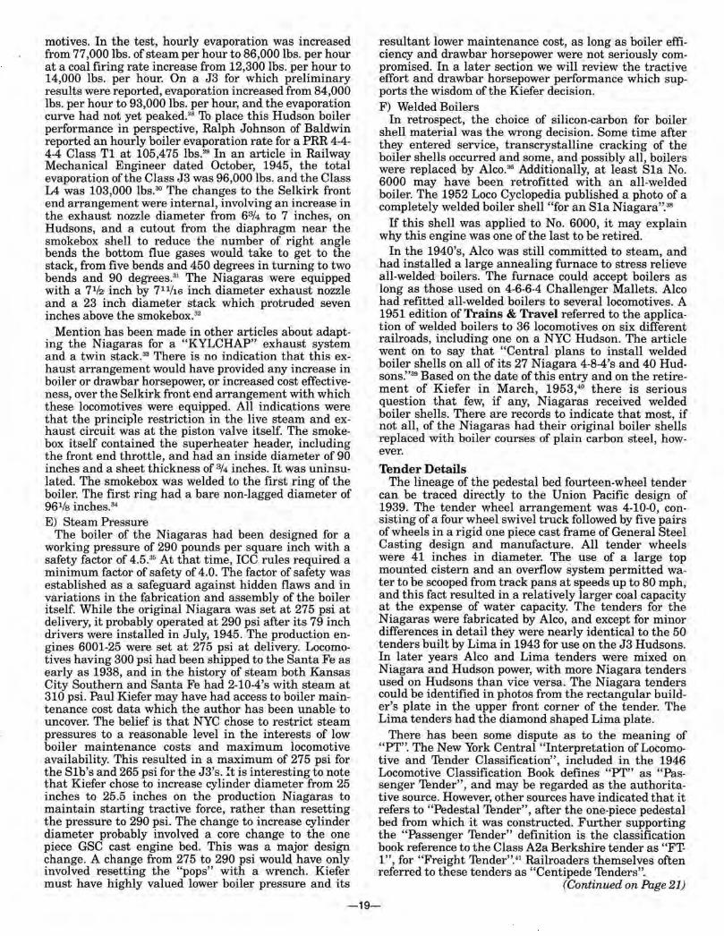
Frame of 51 b #6007 in foreground, boiler and frame of #6008 to rear. Erecting Shop, American Locomotive Company, Schenectady, N.Y., 1945. Alco Historic Photos.
-20-
Locomotive Weight The builder's card for the S1b Niagaras gives an en
gine weight in working order of 471,000 lbs. A tender weight is given at two-thirds load as 337,400 lbs.42 The 1952 Loco Cyclopedia gives a tender weight for a NYC PT tender, fully loaded, as 420,000 lbs.43 The fully loaded engine and tender weight of an S1b was therefore 891,000 lbs., and may have been as much as 898,000 lbs. after the Niagaras were equipped with carbon steel boiler shells.
The Loco Cyclopedia also estimated the light weight of a Niagara engine only, as 423,900 lbs.; and a light weight less engine and trailer trucks and rods as 378,400 lbs.44
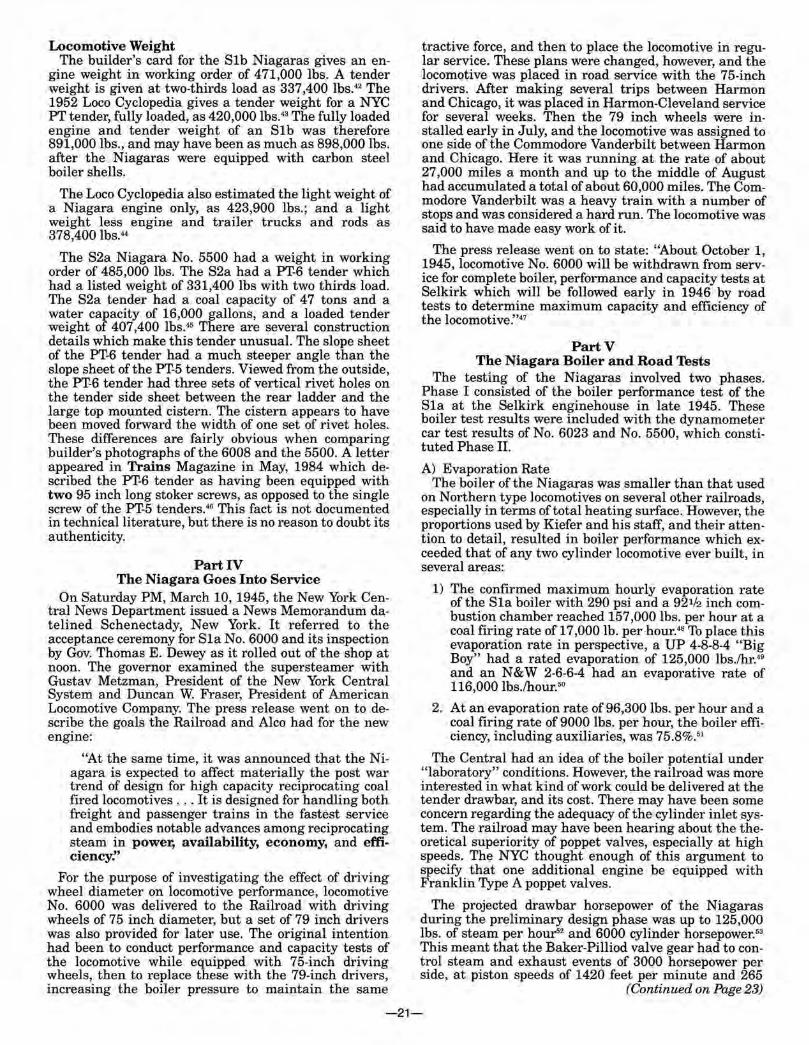
The S2a Niagara No. 5500 had a weight in working order of 485,000 lbs. The S2a had a PT-6 tender which had a listed weight of 331,400 lbs with two thirds load. The S2a tender had a coal capacity of 4 7 tons and a water capacity of 16,000 gallons, and a loaded tender weight of 407,400 lbs.45 There are several construction details which make this tender unusual. The slope sheet of the PT-6 tender had a much steeper angle than the slope sheet of the PT-5 tenders. Viewed from the outside, the PT-6 tender had three sets of vertical rivet holes on the tender side sheet between the rear ladder and the large top mounted cistern. The cistern appears to have been moved forward the width of one set of rivet holes. These differences are fairly obvious when comparing builder's photographs of the 6008 and the 5500. A letter appeared in Trains Magazine in May, 1984 which described the PT-6 tender as having been equipped with two 95 inch long stoker screws, as opposed to the single screw of the PT-5 tenders.46 This fact is not documented in technical literature, but there is no reason to doubt its authenticity.
Part IV The Niagara Goes Into Service
On Saturday PM, March 10, 1945, the New York Central News Department issued a News Memorandum datelined Schenectady, New York. It referred to the acceptance ceremony for S1a No. 6000 and its inspection by Gov. Thomas E. Dewey as it rolled out of the shop at noon. The governor examined the supersteamer with Gustav Metzman, President of the New York Central System and Duncan W. Fraser, President of American Locomotive Company. The press release went on to describe the goals the Railroad and Alco had for the new engine:
"At the same time, it was announced that the Niagara is expected to affect materially the post war trend of design for high capacity reciprocating coal fired locomotives ... It is designed for handling both freight and passenger trains in the fastest service and embodies notable advances among reciprocating steam in power, availability, economy, and efficiency!'
For the purpose of investigating the effect of driving wheel diameter on locomotive performance, locomotive No. 6000 was delivered to the Railroad with driving wheels of 75 inch diameter, but a set of 79 inch drivers was also provided for later use. The original intention had been to conduct performance and capacity tests of the locomotive while equipped with 75-inch driving wheels, then to replace these with the 79-inch drivers, increasing the boiler pressure to maintain the same
tractive force, and then to place the locomotive in regular service. These plans were changed, however, and the locomotive was placed in road service with the 75-inch drivers. After making several trips between Harmon and Chicago, it was placed in Harmon-Cleveland service for several weeks. Then the 79 inch wheels were installed early in July, and the locomotive was assigned to one side of the Commodore Vanderbilt between Harmon and Chicago. Here it was running at the rate of about 27,000 miles a month and up to the middle of August had accumulated a total of about 60,000 miles. The Commodore Vanderbilt was a heavy train with a number of stops and was considered a hard run. The locomotive was said to have made easy work of it.
The press release went on to state: "About October 1, 1945, locomotive No. 6000 will be withdrawn from service for complete boiler, performance and capacity tests at Selkirk which will be followed early in 1946 by road tests to determine maximum capacity and efficiency of the locomotive:'47
PartV The Niagara Boiler and Road Tests
The testing of the Niagaras involved two phases. Phase I consisted of the boiler performance test of the S1a at the Selkirk enginehouse in late 1945. These boiler test results were included with the dynamometer car test results of No. 6023 and No. 5500, which constituted Phase II.
A) Evaporation Rate The boiler of the Niagaras was smaller than that used
on Northern type locomotives on several other railroads, especially in terms of total heating surface. However, the proportions used by Kiefer and his staff, and their attention to detail, resulted in boiler performance which exceeded that of any two cylinder locomotive ever built, in several areas:
1) The confirmed maximum hourly evaporation rate of the S1a boiler with 290 psi and a 92112 inch combustion chamber reached 157,000 lbs. per hour at a coal firing rate of 17,000 lb. per hour.48 To place this evaporation rate in perspective, a UP 4-8-8-4 "Big Boy" had a rated evaporation of 125,000 lbs./hr.49
and an N & W 2-6-6-4 had .an evaporative rate of 116,000 lbs./hour.50
2. At an evaporation rate of 96,300 lbs. per hour and a coal firing rate of 9000 lbs. per hour, the boiler efficiency, including auxiliaries, was 75.8%.5'
The Central had an idea of the boiler potential under "laboratory" conditions. However, the railroad was more interested in what kind of work could be delivered at the tender drawbar, and its cost. There may have been some concern regarding the adequacy of the cylinder inlet system. The railroad may have been hearing about the theoretical superiority of poppet valves, especially at high speeds. The NYC thought enough of this argument to specify that one additional engine be equipped with Franklin Type A poppet valves.
The projected drawbar horsepower of the Niagaras during the preliminary design phase was up to 125,000 lbs. of steam per hour52 and 6000 cylinder horsepower. 53
This meant that the Baker-Pilliod valve gear had to control steam and exhaust events of 3000 horsepower per side, at piston speeds of 1420 feet per minute and 265
(Continued on Page23)
-21-
wheel rpm, corresponding to 60-65 mph with 79 inch drivers. At some point the railroad determined that the actual cylinder horsepower was close to 6700, and the piston valve performance and the performance and life of the Baker gear may have been questioned. B) Franklin Steam Distribution System
The Franklin steam distribution system was advertised to have several advantages over piston valves. A poppet valve engine could be operated at shorter cutoffs than a piston valve engine because on a poppet valve engine the timing of the inlet and exhaust events could be set separately. In a piston valve engine, any inlet setting to favor inlet performance reduced exhaust performance. The reverse was also true. Additionally, a "popper" could take greater advantage of the clearance volume required with piston valve engines, and this would result in greater economy. (The clearance volume was the amount of steam left in the cylinder which acted to "cushion" the piston at the end of its travel and before it reversed direction.) If they were correctly sized, a pop-pet valve engine could flow greater quantities of steam than a piston valve engine, even one with fourteen inch piston valves. Finally, a poppet system required much less horsepower to operate, and mechanical efficiency (and economy) would improve. There were indications that a piston valve system required 50 to 60 horsepower per side to operate; a poppet system absorbed as little as 3 horsepower per side.54 All of this "extra" horsepower went directly to the drawbar.
The Franklin Railway Supply Company was actively promoting the advantages of poppet valves, as shown opposite. (This particular advertisement was contained in the July, 1947 issue of Railway Mechanical Engineer and probably refers to either the Niagara comparison tests or the tests of the PRR T1's.)55
Over-the-road Tests The over-the-road tests of S1b No. 6023 and S2a No.
5500 were the most comprehensive tests ever performed on steam locomotives under actual in-service conditions. The most significant findings of these tests were: C) Cylinder Horsepower
1) Cylinder horsepower readings taken at 5 minute intervals of 6620 hp. for No. 5500 and 6680 hp. for No. 6023.56
D) Drawbar Horsepower 2) Maximum drawbar horsepower of 5070 hp. for No.
6023 and 5000 drawbar hp. for No. 5500.57
3) Both engines exerted in excess of 63,000 lbs. tractive effort at starting with 275 psi boiler pressure and 79 inch driving wheels. Individual tests recorded tractive efforts at starting as high as 65100 lbs. with 79 inch driving wheels and 275 psi. 58
E) Efficiency 4) At a steam rate of 2500 indicated horsepower an
overall efficiency of 4. 77 percent was recorded for No. 6023 and 5.51 percent for No. 5500.59
5) In over-the-road tests, maximum thermal efficiencies of 5.86 percent were recorded for No. 5500 and 4.94 percent for No. 6023.60
6) For tests run at comparatively short cutoffs, the maximum thermal efficiencies were 6.57 and 5.58 percent for No. 5500 and 6023 respectively.61
F) Over-the-road Evaporation During the testing itself, a combined hourly evapora-
tion of 117,630 lbs. of steam was generated in a July,
1946 test of No. 6023. On this test run, 90,320 lbs. were attributed to the boiler, 12,110 were due to the feedwater heater, and 15,200 lbs. by the superheater.62 There are numerous test runs with combined hourly evaporations exceeding 100,000 lbs. per hour from both the 5500 and 6023. None of these tests exceeded the boiler evaporation of No. 6000 at Selkirk, however, and there are conclusions in the combined report which indicate that the boiler of No. 6000 was significantly better than the S1b or the S2a boilers. There were some differences in the methodology: "The boiler performance test results for locomotive 6000 were obtained by holding a constant rate of firing and evaporation over periods of about an hour while, during road tests with five minute observations, peak readings that occur during accelerations after slowdowns were seldom obtained.63
G) S1a, S1b and S2a Comparisons 1) The hourly equivalent evaporation for locomotive
6023 averaged approximately 7500 lbs. under that of locomotive 6000, and 5000 lbs. under that of locomotive 5500.
2) The efficiency of the superheater on locomotive 6000 was approximately 2 percent higher than that for locomotive 6023.
3) The combined boiler efficiency for locomotive 6023 averaged approximately 7 percent under that of locomotive 6000 and 2.5 to 4 percent under that of locomotive 5500.
4) The temperature of the steam at the steam chest for locomotive 6023 averaged from 25 to 30 degrees lower than that for locomotive 6000.
All of these factors would tend to indicate that the indicated horsepower and drawbar horsepower of No. 6000 were up to 6.3 percent better than the 117,500 lbs. of evaporation and 5070 drawbar horsepower of No. 6023. The original Niagara, never tested over the road, probably had over 5450 drawbar horsepower! Arnold Haas quotes an evaporation rate for S1a No. 6000 of 136,000 lbs. per hour; and 537 4 draw bar horsepower at 290 psi for No. 6023.65
The dynamometer testing of 6023 and 5500 revealed a wealth of detail, including superheat temperatures for different firing rates, steam consumed by auxiliaries, cylinder enthalpy, machine friction, and boiler demand factors. The following reproductions of the most notable tests are reproduced in part below, with the author's comments.66
H) Test 107 Engine ................................... 6023 Test number ... . ............................ 107 Series .................................... 46-53
53rd test of 1946 Date ............................... . ... 7/23/46
Smokebox Temp °F .......................... 658 Exhaust steam slightly superheated
Degree of Superheat-max ..................... 348 Degree Superheat @ header °F ................ 329 Temp. °F max steam sup header ................ 761
Could not be maintained in pass. service Draft, front of diaphragm in H20 .. ........... . 16.2 Draft, firebox in H20 .. ....... .... ............ 2.8 Min. back pressure in H20 ..................... 11
High back pressure "robs" horsepower
(Continued on Page 25)
-23-
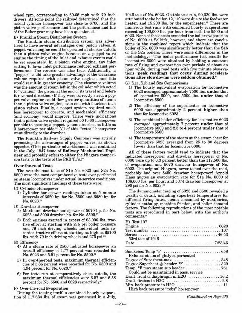
Right and left sides of PT-5 tender, American Locomotive Company, Schenectady, N.Y., November, 1945, Alco Historic Photos.
-24-
Dry coal per hour-lbs ........................ 12090 Nominal firing rate for a Niagara
Evaporation-boiler ......................... 90320 Evaporation-Superheater ................... 15200
Superheater "adds" to boiler evaporation Evaporation-FWH ......................... 12110 Evaporation - Total ........................ 117630
Feedwater preheats water-freeing up boiler capacity Highest "over-the-road" evaporation noted
Coal-BTU's per lb. . ........................ 13796
Indicated Horsepower single reading ............................ 6520
Max. Indicated Horsepower (5 min. readings) .......................... 6680 Highest cylinder horsepower noted
After the test data was analyzed, it became obvious to the NYC Mechanical Department that it had evolved the most powerful and efficient two cylinder locomotives built to that time. But the procurement of motive power to an increasing degree was based on economics, including monthly mileage and utilization, and cost factors including capital cost, maintenance cost, and fuel efficiency. The diesel builders could not compete with steam designs on the basis of drawbar horsepower without greatly increased capital costs and the need to roster many more diesels. So the sales approach of the diesel builders was based on economics. NYC now owned a fleet of the most powerful steamers ever developed. The questions in the minds of the NYC motive power men was - "How would its new Niagaras compare against diesels?"
Part VI The Comparison Test - Niagaras vs. Diesels
In the early 1940's, the New York Central was at a crossroads in regard to its motive power policy. The NYC, as the third largest coal hauler and possessed of a very talented Engineering staff, had an allegiance to the steam locomotive. On-line supplier Alco had a history of successful steam designs and a close association with the railroad. But the NYC had both passenger and freight EMD road diesels on the property in 1945, and they were delivering outstanding performance. NYC no doubt was receiving good reports from other railroads regarding diesel performance. In its usually thorough manner, the railroad decided to perform a test of its newest steam and diesel locomotives in the same service. The measurements would be availability and utilization, and would carefully measure acquisition and operating cost for each type of locomotive.
A) Locomotives Used Six Niagara type steam locomotives and six sets of E7
diesels were cycled under controlled conditions while performance and operating costs were tracked. The engine numbers of the diesels are lost in time, but the Niagara details are still available. N:iagaras 6007, 6009, 6012, 6024, 6025, and 5500 were used. 67 An effort was made to keep both types of locomotives operating continuously during the six month test period.
B) Monthly Mileages The test began early in 1946 with the assignment of
six diesel sets to three eastbound and three westbound schedules, one in each direction between Harmon and Chicago, and two between Harmon and Mattoon,
Illinois, the assigned train service mileage per day being, respectively, 928 and 1000. The six locomotives averaged 29,021 miles per unit per month, or 954 per day.
Beginning October 1 of the same year, six of the Niagara steam, including the one equipped with poppet valves, were assigned to three westbound and three eastbound runs between Harmon and Chicago. Up to the end of November, these engines averaged 26,168 miles monthly, or 858 per day.
The strike in the bituminous coal mines caused a disruption of this arrangement for thirteen days during December, and the engines were assigned to other runs during this period. The total mileage for the three months beginning October 1 was 455,404, or an average of25,300 miles per month per engine.68
C) Predicted Annual Performance Paul Kiefer in his book A Practical Evaluation of
Railroad Motive Power reproduced the following table predicting the potential performance of each type of locomotive:
Annual Potential Performance Per Locomotive Diesel Steam
Total hours 8760 8760 Hour for shopping and
periodic inspections 288 672 Assigned hours 84 72 8088 Hours used 6292 6080 Hours available-not used 338 573 Hours unavailable 1842 1435 Percent utilization 71.8 69.4 Percent availability 75.7 75.9 Mileage operated 329934 314694 Average miles per month 27 496 26226 Average miles per day 904 862
Kiefer went on to say that steam performance would deteriorate in severe weather, and forecasted the following potential annual performance:
Annual mileage Average miles per month Utilization, Percent of Total
Annual Hrs. Availability
D) Train Cycle Charts
Diesel Steam 324000 288000
27000 24000
70.4 74.2
63.0 69.0
A critical measure of performance on NYC was on-time performance. Accordingly, a study was made of delays en route and at division terminals between Harmon and Buffalo, 403 miles, for six Niagaras and six diesels in through service during October, 1946.
Both types of power received the same preferred attention at terminals, and coal of a somewhat higher grade than normal was provided for the steam units. The record for 356 trains, 179 for steam and 177 for the diesels, were examined, with the following average results in minutes:
Gross Delay Running time made up Net time late at final terminal Gross delay chargeable
to Locomotive
Diesel Steam 16.1 21.1 13.9 17.6 2.2 3.5
1.3 1.2 (Continued on Page 27)
-25-
~------------'--~NMOViOVEEMMaEI'ITS OF •s" TEST ENGiNES. ocTO.er.R til4e
~~--------~~-====~~~=~==~--~------~
~IIJL!WOOO -ElkHMT -
TOI.EDO -COU.INWOOO •
IIII'PALO _ on•n _
ft!!mSELA!II
tiiOLEWooo ELKIIAAT
TOLI':OO OCit.UIIWOOO
iur'ALO DEWITT
iltNSSELAat IWIMoN
l~~ ELIIHARt. llX.IDO ... ~-,
IUFf'M.O ·\~.(ioo.;:.niJ!J·~f1f§';§~~~p~~~b'"""'~h.::-:::-l D£WJTT • \ llfM!I!LAER • \
26 ~78 NILES
~~~--------~------------~--------------------~--~--~--~----~=
28,681 lot1L£S
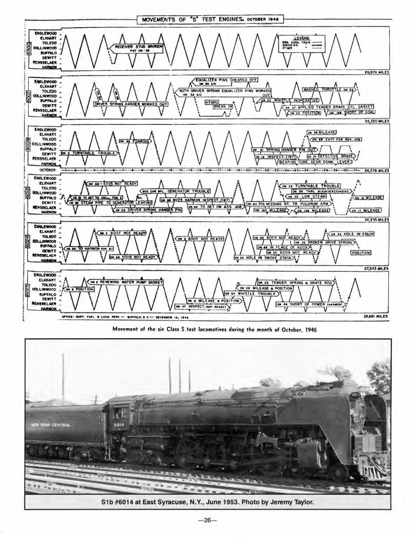
Movement of the six Class S test locomotives during the month of October, 1946
S1b #6014 at East Syracuse, N.Y., June 1953. Photo by Jeremy Taylor.
-26-
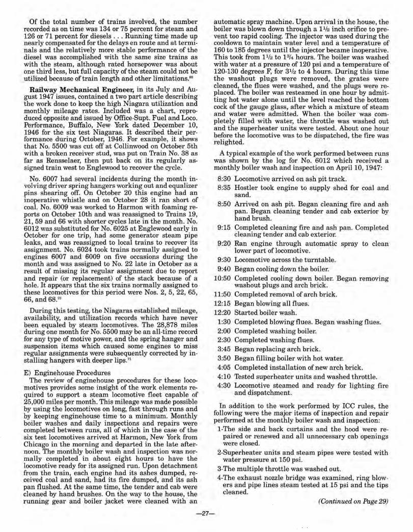
Of the total number of trains involved, the number recorded as on time was 134 or 75 percent for steam and 126 or 71 percent for diesels ... Running time made up nearly compensated for the delays en route and at terminals and the relatively more stable performance of the diesel was accomplished with the same size trains as with the steam, although rated horsepower was about one third less, but full capacity of the steam could not be utilized because of train length and other limitations. 59
Railway Mechanical Engineer, in its July and August 194 7 issues, contained a two part article describing the work done to keep the high Niagara utilization and monthly mileage rates. Included was a chart, reproduced opposite and issued by Office-Supt. Fuel and Loco. Performance, Buffalo, New York dated December 10, 1946 for the six test Niagaras. It described their performance during October, 1946. For example, it shows that No. 5500 was cut off at Collinwood on October 5th with a broken receiver stud, was put on Train No. 38 as far as Rensselaer, then put back on its regularly assigned train west to Englewood to recover the cycle.
No. 6007 had several incidents during the month involving driver spring hangers working out and equalizer pins shearing off. On October 20 this engine had an inoperative whistle and on October 28 it ran short of coal. No. 6009 was worked to Harmon with foaming reports on October lOth and was reassigned to Trains 19, 21, 59 and 66 with shorter cycles late in the month. No. 6012 was substituted for No. 6025 at Englewood early in October for one trip, had some generator steam pipe leaks, and was reassigned to local trains to recover its assignment. No. 6024 took trains normally assigned to engines 6007 and 6009 on five occasions during the month and was assigned to No. 22 late in October as a result of missing its regular assignment due to report and repair (or replacement) of the stack because of a hole. It appears that the six trains normally assigned to these locomotives for this period were Nos. 2, 5, 22, 65, 66, and 68.70
During this testing, the Niagaras established mileage, availability, and utilization records which have never been equaled by steam locomotives. The 28,878 miles during one month for No. 5500 may be an all-time record for any type of motive power, and the spring hanger and suspension items which caused some engines to miss regular assignments were subsequently corrected by installing hangers with deeper lips.71
E) Enginehouse Procedures The review of enginehouse procedures for these loco
motives provides some insight of the work elements required to support a steam locomotive fleet capable of 25,000 miles per month. This mileage was made possible by using the locomotives on long, fast through runs and by keeping enginehouse time to a minimum. Monthly boiler washes and daily inspections and repairs were completed between runs, all of which in the case of the six test locomotives arrived at Harmon, New York from Chicago in the morning and departed in the late afternoon. The monthly boiler wash and inspection was normally completed in about eight hours to have the locomotive ready for its assigned run. Upon detachment from the train, each engine had its ashes dumped, received coal and sand, had its fire dumped, and its ash pan flushed. At the same time, the tender and cab were cleaned by hand brushes. On the way to the house, the running gear and boiler jacket were cleaned with an
automatic spray machine. Upon arrival in the house, the boiler was blown down through a l 1/2 inch orifice to prevent too rapid cooling. The injector was used during the cooldown to maintain water level and a temperature of 160 to 185 degrees until the injector became inoperative. This took from l 1/2 to 13/4 hours. The boiler was washed with water at a pressure of 120 psi and a temperature of 120-130 degrees F, for 31/2 to 4 hours. During this time the washout plugs were removed, the grates were cleaned, the flues were washed, and the plugs were replaced. The boiler was resteamed in one hour by admitting hot water alone until the level reached the bottom cock of the gauge glass, after which a mixture of steam and water were admitted. When the boiler was completely filled with water, the throttle was washed out and the superheater units were tested. About one hour before the locomotive was to be dispatched, the fire was relighted.
A typical example of the work performed between runs was shown by the log for No. 6012 which received a monthly boiler wash and inspection on AprillO, 1947:
8:30 Locomotive arrived on ash pit track. 8:35 Hostler took engine to supply shed for coal and
sand. 8:50 Arrived on ash pit. Began cleaning fire and ash
pan. Began cleaning tender and cab exterior by hand brush.
9:15 Completed cleaning fire and ash pan. Completed cleaning tender and cab exterior.
9:20 Ran engine through automatic spray to clean lower part of locomotive.
9:30 Locomotive across the turntable. 9:40 Began cooling down the boiler.
10:50 Completed cooling down boiler. Began removing washout plugs and arch brick.
11:50 Completed removal of arch brick. 12:15 Began blowing all flues. 12:20 Started boiler wash.
1:30 Completed blowing flues. Began washing flues. 2:00 Completed washing boiler. 2:30 Completed washing flues. 3:45 Beganreplacing arch brick. 3:50 Began filling boiler with hot water. 4:05 Completed installation of new arch brick. 4:10 Tested superheater units and washed throttle. 4:30 Locomotive steamed and ready for lighting fire
and dispatchment.
In addition to the work performed by ICC rules, the following were the major items of inspection and repair performed at the monthly boiler wash and inspection:
1-The side and back curtains and the hood were repaired or renewed and all unnecessary cab openings were closed.
2-Superheater units and steam pipes were tested with water pressure at 150 psi.
3-The multiple throttle was washed out. 4-The exhaust nozzle bridge was examined, ring blow
ers and pipe lines steam tested at 15 psi and the tips cleaned.
(Continued on Page 29)
-27-
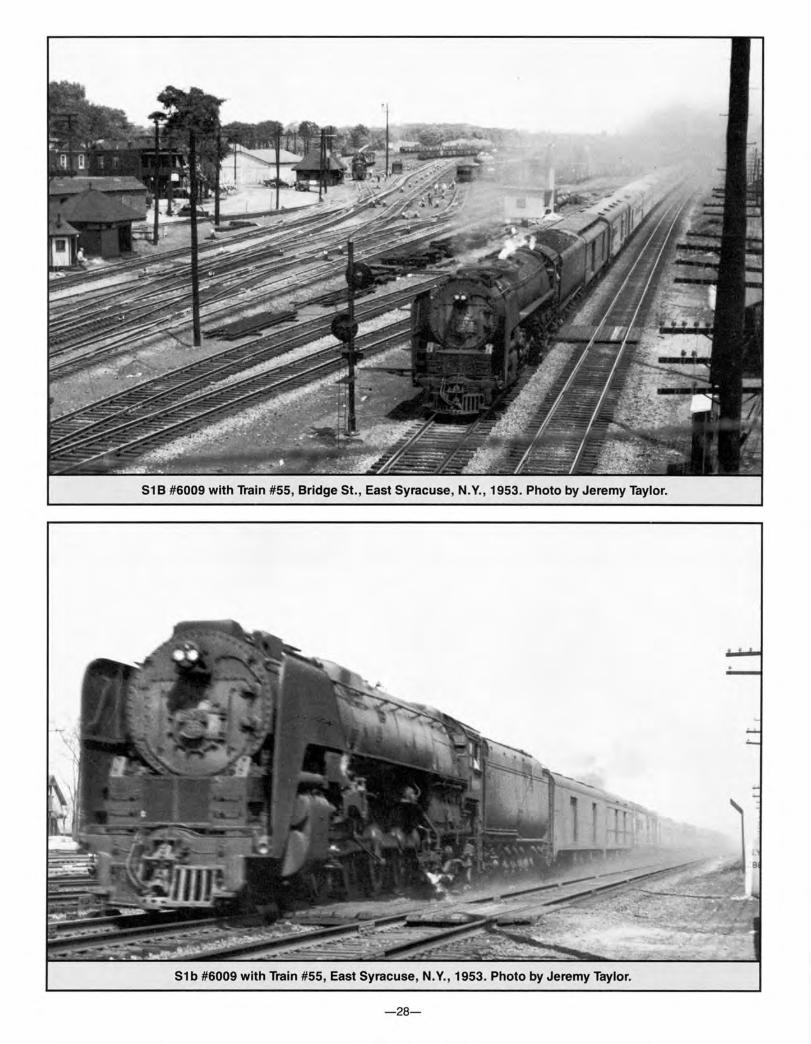
S1B #6009 with Train #55, Bridge St., East Syracuse, N.Y., 1953. Photo by Jeremy Taylor.
S1b #6009 with Train #55, East Syracuse, N.Y. , 1953. Photo by Jeremy Taylor.
- 28-
5-Eccentric rods, pins, and cranks were removed, cleaned and magnafluxed on the piston valve locomotives.
6-The front end main rod lateral was checked. 7-The condition of the cylinder packing was examined
and a measurement of packing wear was taken. 8-Boiler checks were ground-in, shut off valves checked
and repaired. The intermediate check valve of the feedwater pump discharge line was examined and ground.
9-All universal joints to valves in and outside of the cab were inspected and repaired.
10-Low water alarm bodies were washed out and the main openings reamed. After the locomotive was fired up the alarm was tested.
11-The stoker distributing jets were renewed if worn and the hook bolts tightened if loose. The bonnets and stems of the bypass valves in the individual jet valves were examined for wear and renewed or repacked if necessary.
12-The oil was drained and changed in the cold water centrifugal feedwater pump.
13-The force feed lubricator was operated by hand to make sure the pipes were open and free of leakage.
14-The grates, grate rigging, and carrier irons were checked for defects.
Subject to inspection, a number of small jobs were performed, such as grinding in boiler checks, repacking all cab valves, reaming the water gauges, testing low water alarm, etc. For larger jobs, machinists with helpers were assigned. One pair cleans, magnafluxes, and inspects motion work. Another pair removes cylinder heads and examines cylinder packing. Available machinists were assigned to clean, flush, and examine the roller bearings. The front end main rod lateral was checked with a small gauge similar to a surface gauge after the rod was barred over to both limits of its lateral travel.
The second installment of the RME Niagara article described the work done on the Niagaras during their quarterly inspections. Fortunately, the engined which received its quarterly for the article was S2a No. 5500. The engine was at Harmon for this work on March 5, 1947, and had accumulated 166,114 miles since it was new. Its mileage since its last quarterly on December 5, 1946 was 71,450. Thus the locomotive averaged nearly 24,000 miles per month despite the fact that its mileage was adversely affected by a short month (February) and by the coal strike.
A recondition quarterly, which is given at the end of every other three month period, was performed with the single exception that the tires were not turned. This was not done because the tires were in good condition and it was decided to dispense with the tire turning at this time as the engine was scheduled to undergo dynamometer-car tests in the near future and would be tied up for outfitting long enough to permit the tires to be turned.
The organization of manpower for quarterly inspection and repairs differed from the monthly boiler wash lineup mainly with respect to the use and division of machinists. The extensive work done on the machinery necessitated the employment of a larger machinist gang divided into the following groups:
- One machinist and one helper handled stokers, hot water pumps, injectors, boiler checks, blow-off cocks, and the steam whistle.
- One machinist and one helper was assigned to the Valve Pilot and rod work.
-Two machinists and two helpers worked on the rods, cylinder packing, valve setting and spring work.
-Two machinists and two helpers handled wheel and spring work on the drop pit.
- One machinist and one helper did the cab work and miscellaneous ICC inspection work.
- One machinist and one helper inspected and made repairs to the air brakes, air pump, and brake cylinders.
- One machinist and one helper made repairs to the tank brake rigging and inspected the drawbars.
- One machinist and one helper worked on force-feed lubricators, tight-lock couplers, cab cocks, and other small jobs.
The major items of inspection and/or repair on the 5500 were as follows:
The superheater units, steam pipes, exhaust pipes and nozzle were tested with 150 psi water pressure and found to be satisfactory. The multiple throttle was washed out to remove the mud accumulation. The exhaust valve bridge was examined. This was not renewed as the use of Ni-hard tips largely eliminated the need for tip renewal. One cinder shield was renewed because of wear. The continuous blowdown system was checked and found satisfactory.
A spare set of main and side rods was applied. These rods were taken from No. 6022 and had all the necessary repairs and tests made to them ... Repairs to these rods included new bronze bushings applied and rolled, which was done after the Magnaflux test showed the rods to be satisfactory. The rollers were cleaned and visually inspected for defects and all new fiber spacers installed to control the lateral. The axle roller bearings were adjusted at classified repairs only.
The oil in the rod roller bearings was renewed, the felt retainers checked, and all retainers renewed. The Timken split-type multiple-guide crosshead and its bolts were magnafluxed, and it was assembled with a .015 inch draw. The flame hardened guides were checked for wear and reconditioned crosshead slippers, rebabbited at West Albany Shops and machined to .020 inch clearance at Harmon, were applied. The wrist-pin roller bearing was set to zero clearance. In the driving wheel, engine-truck, trailer-truck and tender roller bearings the oil was drained, the box flushed with kerosene and the oil renewed. Settings on these bearing assemblies were performed at classified repairs only. All enclosure bolts on the driving box and plates were checked and tightened. The main and side rod crank pins were cleaned and checked for defects.
The poppet valve-gear system, after examination and reassembly, was set by the dial indicator which is mounted on the outside of the cylinder assembly and shows where the various events of the steam cycle take place. The necessary adjustments were made by taking up on the camshaft connecting rod. The poppet valves were magnafluxed and all returned to service, none of the 12 exhaust nor 8 inlet valves requiring replacement.
All boiler checks were ground in. Shut off valves were examined and had minor repairs made to them. The
(Continued on Page 31)
-29-

S1b #6020 with Train #43, Newark, N.Y., February 1953. Photo by Jeremy Taylor.
S1b #6001 and J1b #5204 with Train #137, Buffalo, N.Y., August 1953. Photo by Jeremy Taylor.
-30-
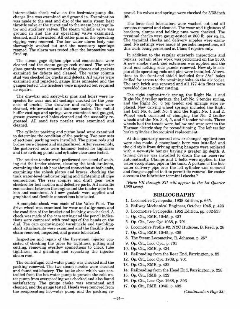
intermediate check valve on the feedwater-pump discharge line was examined and ground in. Examination was made to the seat and disc of the main steam heat throttle valve at the turret and to the steam heat regulator and auxiliary valves. The steam whistle valve was ground in and the air operating valve examined, cleaned, and lubricated. All cotter pins in the operating rigging were renewed. The low water alarm body was thoroughly washed out and the necessary openings reamed. The alarm was tested after the locomotive was fired up.
The steam gage siphon pipe and connections were cleaned and the steam gauge cock reamed. The water glass guards were removed and the glasses and gaskets examined for defects and cleaned. The water column stud was checked for cracks and defects. All valves were examined and repacked, gauge lines annealed and the gauges tested. The firedoors were inspected but required no repairs.
The drawbar and safety-bar pins and holes were inspected for wear and all castings checked for the presence of cracks. The drawbar and safety bars were cleaned, whitewashed and hammer tested. The radial buffer castings and springs were examined and gauged, grease grooves and holes cleaned and the assembly regreased. All sand trap nozzles were examined and cleaned.
The cylinder packing and piston head were examined to determine the condition of the packing. Two new sets of sectional packing were installed. The piston rods and bodies were cleaned and magnafluxed. After reassembly the piston-rocj. nuts were hammer tested for tightnes~ and the striking points and cylinder clearance tested.
The routine tender work performed consisted of washing out the tender cistern, cleaning the tank strainers, examining the tank hose thread connection at both ends, examining the splash plates and braces, checking the tank water-level-indicator piping and tightening all pipe connections. The rear coupler and draft gear were checked for lost motion and defective parts. All metallic connections between the engine and the tender were broken and examined. All new gaskets were applied and graphited and flexible connections lubricated.
A complete check was made of the Valve Pilot. The drive wheel was examined for wear and alignment and the condition of the bracket and bushing was checked. A check was made of the cam setting and the pencil indications were compared with readings of the hands on the dial. The cam operating-rod turnbuckle and tumblingshaft attachments were examined and the flexible drive chain removed, inspected, and grease lubricated.
Inspection and repair of the live-steam injector consisted of checking the tubes for tightness, pitting and cutting, removing overflow connections to check tube tightness, and grinding and repacking the injector steam ram.
The centrifugal cold-water pump was checked and the packing renewed. The two steam nozzles were checked and found satisfactory. The brake shoe which was controlled from the hot-water pump to prevent the cold-water pump from overspeeding was checked and also found satisfactory. The gauge choke was examined and cleaned, and the gauge tested. Heads were removed from the reciprocating hot-water pump and the packing re-
newed. Its valves and springs were checked for 3/32-inch lift.
The force feed lubricators were washed out and all screens removed and cleaned. The wear and tightness of brackets, clamps and holding nuts were checked. The terminal checks were gauge-tested at 300 lb. per sq. in. The terminal checks and delivery nipples were examin~d. No set~ings were made at periodic inspections, all this work bemg performed at Class 3 repairs only.
In addition to the regular quarterly inspections and repairs, certain other work was performed on the 5500. A new smoke stack and extension was applied and the front end netting side panels renewed. New-style ashpan-slide operating rods and pins were installed. Alterations to the front-end shield included four 31/z" holes drilled for access to the retaining bolts on the air cooler. The arch brick was renewed and all 177 4-in flues were rewelded due to cinder cutting.
The right engine-truck spring, the Right No. 1 and Right No.~ trailer springs, the Left No. 2 tender spring, and the Right No. 3 top tender coil springs were replaced. New driving wheel springs included the Right and Left No. 4, Left No. 3 and the Right No. 1 and 2. Wheel work consisted of changing the No. 2 trailer wheels and the No.3, 4, 5, and 6 tender wheels. These wheels had the treads worn hollow and were sent to the Harmon electric shop for reconditioning. The left trailer brake cylinder also required replacement.
At this quarterly several new or changed applications were also made. A pneuphonic horn was installed and t~e old style front driving spring hangers were replaced with a new-style hanger having a greater lip depth. A timing device was installed to drain the air reservior automatically. Clamps and U-bolts were applied to the water-scoop stand pipe in the tank. A portion of the hotwater delivery pipe over the left cylinder was removed and flanges applied to it to permit its removal for easier access to the lubricator terminal checks.72
(Parts VII through XII will appear in the 1st Quarter 1989 issue)
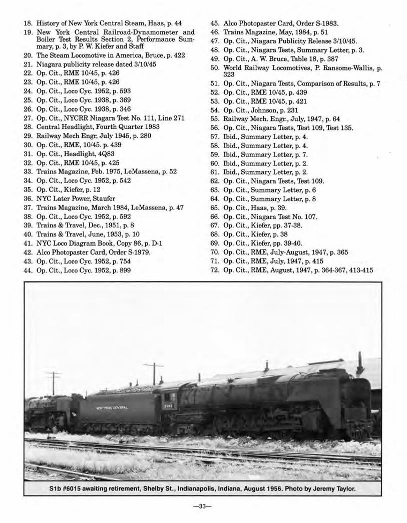
BIBLIOGRAPHY 1. Locomotive Cyclopedia, 1938 Edition, p. 665. 2. Railway Mechanical Engineer, October 1945, p. 423 3. Locomotive Cyclopedia, 1952 Edition, pp. 532-533 4. Op. Cit., RME, 10/45, p. 427 5. Op. Cit., Loco Cyc 1938, p. 701 6. Locomotive Profile #2, NYC Hudsons, B. Reed, p. 28 7. Op. Cit., RME, 10/45, p. 439 8. The Steam Locomotive, R. Johnson, p. 257 9. Op. Cit., Loco Cyc., p. 701
10. Op. Cit., RME, p. 424 11. Railroading from the Rear End, Farrington, p. 89 12. Op. Cit., Loco Cyc. 1938, p. 701 13. Op. Cit., RME, p. 422 14. Railroading from the Head End, Farrington, p. 228 15. Op. Cit., RME, p. 422 16. Op. Cit., Loco Cyc. 1938, p. 393 17. Op. Cit., RME, 10/45, p. 439
(Continued on Page 33)
-31-

S1b #6002 with Train #122, Swan St., Buffalo, N.Y., August 1953. Photo by Jeremy Taylor.
51 b #6009 with Train #473, Terre Haute, Indiana, Spring, 1954. Photo by Jeremy Taylor.
- 32-
18. History of New York Central Steam, Haas, p. 44 19. New York Central Railroad-Dynamometer and
Boiler Test Results Section 2, Performance Summary, p. 3, by P. W. Kiefer and Staff
20. The Steam Locomotive in America, Bruce, p. 422 21. Niagara publicity release dated 3/10/45 22. Op. Cit., RME 10/45, p. 426 23. Op. Cit., RME 10/45, p. 426 24. Op. Cit., Loco Cyc. 1952, p. 593 25. Op. Cit., Loco Cyc. 1938, p. 369 26. Op. Cit., Loco Cyc. 1938, p. 346 27. Op. Cit., NYCRR Niagara Test No. 111, Line 271 28. Central Headlight, Fourth Quarter 1983 29. Railway Mech Engr, July 1945, p. 280 30. Op. Cit., RME, 10/45. p. 439 31. Op. Cit., Headlight, 4Q83 32. Op. Cit., RME 10/45, p. 425 33. Trains Magazine, Feb. 1975, LeMassena, p. 52 34. Op. Cit., Loco Cyc. 1952, p. 542 35. Op. Cit., Kiefer, p. 12 36. NYC Later Power, Staufer 37. Trains Magazine, March 1984, LeMassena, p. 47 38. Op. Cit., Loco Cyc. 1952, p. 592 39. Trains & Travel, Dec., 1951, p. 8 40. Trains & Travel, June, 1953, p. 10 41. NYC Loco Diagram Book, Copy 86, p. D-1 42. Alco Photopaster Card, Order S-1979. 43. Op. Cit., Loco Cyc. 1952, p. 754 44. Op. Cit., Loco Cyc. 1952, p. 899
45. Alco Photopaster Card, Order S-1983. 46. Trains Magazine, May, 1984, p. 51 47. Op. Cit., Niagara Publicity Release 3/10/45. 48. Op. Cit., Niagara Tests, Summary Letter, p. 3. 49. Op. Cit., A. W. Bruce, Table 18, p. 387 50. World Railway Locomotives, P. Ransome-Wallis, p.
323 51. Op. Cit., Niagara Tests, Comparison of Results, p. 7 52. Op. Cit., RME 10/45, p. 439 53. Op. Cit., RME 10/45, p. 421 54. Op. Cit., Johnson, p. 231 55. Railway Mech. Engr., July, 1947, p. 64 56. Op. Cit., Niagara Tests, Test 109, Test 135. 57. Ibid., Summary Letter, p. 4. 58. Ibid., Summary Letter, p. 4. 59. Ibid., Summary Letter, p. 7. 60. Ibid., Summary Letter, p. 2. 61. Ibid., Summary Letter, p. 2. 62. Op. Cit., Niagara Tests, Test 109. 63. Op. Cit., Summary Letter, p. 6 64. Op. Cit., Summary Letter, p. 8 65. Op. Cit., Haas, p. 39. 66. Op. Cit., Niagara Test No. 107. 67. Op. Cit., Kiefer, pp. 37-38. 68. Op. Cit., Kiefer, p. 38 69. Op. Cit., Kiefer, pp. 39-40. 70. Op. Cit., RME, July-August, 1947, p. 365 71. Op. Cit., RME, July, 1947, p. 415 72. Op. Cit., RME, August, 1947, p. 364-367,413-415
S1b #6015 awaiting retirement, Shelby St., Indianapolis, Indiana, August 1956. Photo by Jeremy Taylor.
-33-


![PHOTOGRAPHS OF NIAGARA, MARINETTE … of Niagara... · PHOTOGRAPHS OF NIAGARA, MARINETTE COUNTY, WISCONSIN [Compiled and Captioned by William John Cummings] 3 View of Niagara, Wisconsin,](https://img.pdfslide.us/doc/110x75/5b993acd09d3f207308b54bc/photographs-of-niagara-marinette-of-niagara-photographs-of-niagara-marinette.jpg)


![Legacy Landing · Niagara Region Legacy Landing - 1849 Four Mile Creek Road Legend Notes 111B"] in F ad 0.25 retto Dr ve o 0.5 0.5 Kilometers 2018 - The Regional Municipality of Niagara](https://img.pdfslide.us/doc/110x75/5fcf7057745f211d3506005b/legacy-landing-niagara-region-legacy-landing-1849-four-mile-creek-road-legend.jpg)