Embed Size (px)
Citation preview
The Life Cycle of an Enterprise
Theodore J. Williams and Hong LiInstitute for Interdisciplinary Engineering StudiesPurdue University1293 Potter Center, West Lafayette, IN 47907-1293 USA,Phone: 765/494-7434, Fax: 765/494-2351, e-mail:[email protected]
Peter Bernus and Gregory UppingtonSchool of Computing and Information TechnologyGriffith UniversityNathan (Brisbane), Queensland 4111, AUSTRALIAPhone: 61 7 3875 5039, Fax: 61 7 3875 5051, e-mail:[email protected]
Laszlo NemesManufacturing Systems, CSIROPreston (Melbourne), Victoria 3072, AUSTRALIAPhone: 61 3 9662 7707, Fax: 61 3 9662 7852, e-mail:[email protected]
Abstract
The Enterprise Life Cycle is the basis for most Enterprise IntegrationArchitectures being proposed today. A life cycle representation also forms anexcellent model of the application methodology which must accompany thearchitecture to form a complete set of aids for the engineer contemplating anenterprise engineering or related project. As the life cycle representation has also been extensively used in softwareengineering projects, the relationship of such representations to those usedexpressly for enterprise integration studies is also covered here.
Keywords
Life Cycle, Enterprise Integration, Software Engineering, EnterpriseIntegration Engineering Methodologies
1 INTRODUCTION
Everything in this world must have a beginning, a purpose and finally anending. Even the Judeo-Christian Bible starts with the words, “In thebeginning ....” Even more important, every identified entity can be consideredto go through the same series of phases or stages of its life in its progress fromits beginning to its final ending. Such a progression can be captured in agraphical or narrative description which has come to be called the Life Cycleof the enterprise being discussed. Since such a description can capture theprogressive stages in the life time of any entity, it must, by reference, be ableto describe the necessary steps in the development of any future entity orenterprise. This is a basic concept of all of systems engineering and isuniversally applied even though the names and description of the stages orphases involved will vary greatly from author to author depending on thespecific purpose of each in their writings. In addition to its presentation of the development cycle of the enterprise, thissame diagram, if properly designed, can also be used to show many aspectsand attributes of the developing enterprise at any and all stages of its life cycle.It can thus provide the basis for the preparation of a methodology for carryingout the development program for producing a new enterprise. This chapter will discuss the Life Cycle as it has been developed and used inthe systems engineering field and particularly how it has been recently appliedin the development of the so-called Enterprise Reference Architectures as usedin the field of Enterprise Integration. In this discussion an enterprise will beconsidered to be any physical or virtual entity for which a specific mission hasbeen prescribed (IFAC/IFIP Task Force, 1993).
2 A BIT OF HISTORY
The establishment of Systems Engineering as a major topic of endeavor isgenerally credited to the American Telephone and Telegraph Company(AT&T) in the late 1940s (Hall, 1962). Systems Engineering was first taughtas a course at MIT by Bell Telephone personnel in 1950. Bell Laboratories ofAT&T wrote texts on this subject and taught internal courses to their personnelthroughout the 1950s. The telephone company’s concerns appear to have been concentrated oncompatibility problems between components and on the overall economics ofthe various systems designed. Likewise, emphasis was placed on the use ofmathematical programming techniques and computers for design optimization.There appears to have been no concern for life cycle considerations at thispoint. Indeed, the early classical texts in this field make no mention of thistopic (Hall, 1962; Machol, 1965). The same was true of the general literatureof the field (Williams, 1961). Each of the phases -- analysis, preliminary anddetailed design, etc. -- were recognized in their own right but, for some reason,not yet put together in the whole consideration that became life cycle-basedsystems engineering (Williams, 1961).
3 REPRESENTATION OF THE LIFE CYCLE
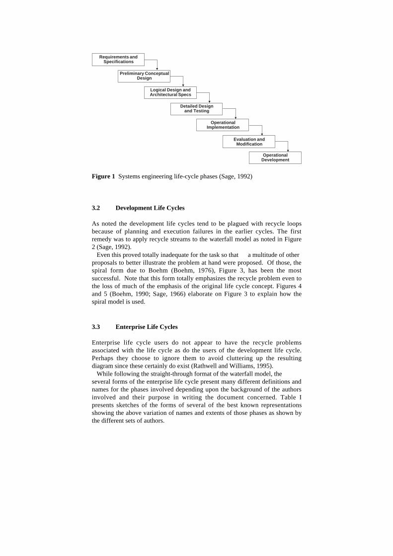
The earliest use of the life cycle as the representation of the consecutiveoperations in the overall lifetime of a systems engineering project and itsenterprise or entity product seems to have been the “waterfall” model due toRoyce (Royce, 1970) as shown in Figure 1 from Sage (Sage, 1992). The initialdiagrams were straight-through models with each phase completed before thenext was started. However, this simplistic model quickly ran into difficulties as allpractitioners immediately recognized that downstream problems continuallyarose in later phases due to incomplete or erroneous planning and execution inthe earlier phases. The history of life cycle engineering has thus been repletewith multiple proposals for dealing with the resulting “recycles” in the overalldevelopment cycles.
3.1 Complete Enterprise Life Cycles Versus Development Life Cyclesin Software Systems
Although this text is primarily for the field of life cycle engineering as appliedto enterprise integration, it is important at this point to show that the use of thelife cycle apparently originated in the software development field and its majoruse has been in that field. As will be pointed out here, the distinctly differentneeds of these two fields have resulted in entirely different forms of the lifecycle representation and a resulting confusion when the representation fromone was used in the other. Enterprise integration tends to involve long-term projects with distinctphases from initial concept by the enterprise management through all thephases to be described below including operation of the resulting factory orother enterprise. This continues on until the final obsolescence and renovationor disposal of the buildings, equipment, etc., involved (Browne, et al., 1995). The software development field tends (but not totally, of course) towardshorter projects, the requirements for which are given by the ultimate users ofthe software being developed. As noted above, those phases involve muchrecycling since the requirements are seldom complete or completely correct.The result of the endeavor is a product to be used by others. While thedevelopers may be charged with maintenance, they are not usually chargedwith the obsolescence and disposal problem of the plant. Thus thedevelopment life cycle is usually foreshortened compared to the enterprise lifecycle. Compare Figure 1 with those of the Enterprise Life Cycle presented later inthis chapter in Table I. We should be quick to point out that even the above is not alwayscompletely true since business process reengineering, concurrent engineering,etc., from the enterprise engineering field often operate like development lifecycle projects rather than complete enterprise engineering life cycles.However, the distinction is valuable and will be used in this chapter with theabove caveats.
Preliminary ConceptualDesign
Detailed Designand Testing
OperationalImplementation
Evaluation andModification
Requirements andSpecifications
Logical Design andArchitectural Specs
OperationalDevelopment
Figure 1 Systems engineering life-cycle phases (Sage, 1992)
3.2 Development Life Cycles
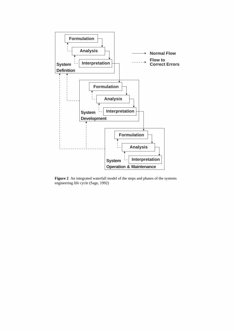
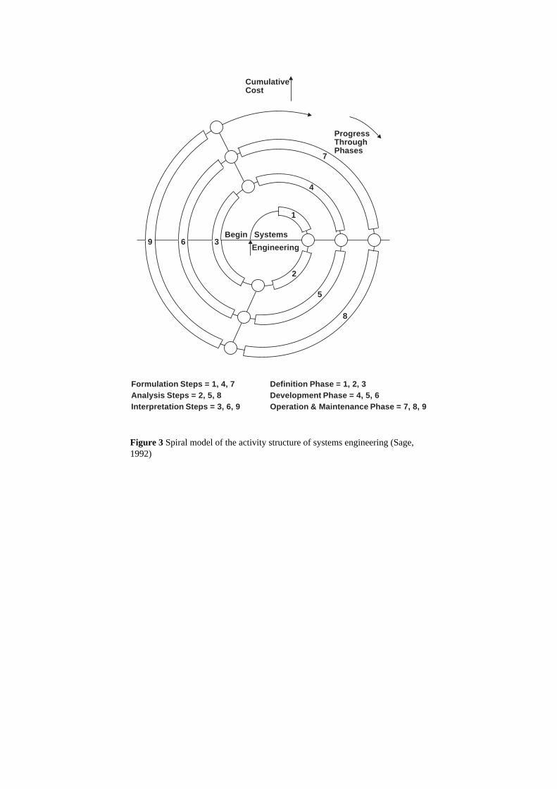
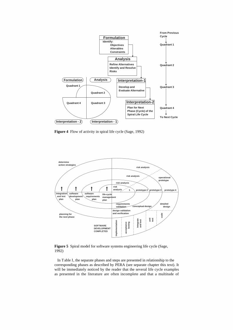
As noted the development life cycles tend to be plagued with recycle loopsbecause of planning and execution failures in the earlier cycles. The firstremedy was to apply recycle streams to the waterfall model as noted in Figure2 (Sage, 1992). Even this proved totally inadequate for the task so that a multitude of otherproposals to better illustrate the problem at hand were proposed. Of those, thespiral form due to Boehm (Boehm, 1976), Figure 3, has been the mostsuccessful. Note that this form totally emphasizes the recycle problem even tothe loss of much of the emphasis of the original life cycle concept. Figures 4and 5 (Boehm, 1990; Sage, 1966) elaborate on Figure 3 to explain how thespiral model is used.
3.3 Enterprise Life Cycles
Enterprise life cycle users do not appear to have the recycle problemsassociated with the life cycle as do the users of the development life cycle.Perhaps they choose to ignore them to avoid cluttering up the resultingdiagram since these certainly do exist (Rathwell and Williams, 1995). While following the straight-through format of the waterfall model, theseveral forms of the enterprise life cycle present many different definitions andnames for the phases involved depending upon the background of the authorsinvolved and their purpose in writing the document concerned. Table Ipresents sketches of the forms of several of the best known representationsshowing the above variation of names and extents of those phases as shown bythe different sets of authors.
Interpretation
Analysis
Formulation
SystemDevelopment
Interpretation
Analysis
Formulation
SystemDefinition
Interpretation
Analysis
Formulation
SystemOperation & Maintenance
Normal Flow
Flow toCorrect Errors
Figure 2 An integrated waterfall model of the steps and phases of the systemsengineering life cycle (Sage, 1992)
Begin Systems
Engineering
1
2
4
5
7
8
9 6 3
CumulativeCost
ProgressThroughPhases
Formulation Steps = 1, 4, 7Analysis Steps = 2, 5, 8Interpretation Steps = 3, 6, 9
Definition Phase = 1, 2, 3Development Phase = 4, 5, 6Operation & Maintenance Phase = 7, 8, 9
Figure 3 Spiral model of the activity structure of systems engineering (Sage,1992)
FormulationIdentify:
ObjectivesAlterablesConstraints
Interpretation-2Plan for NextPhase (Cycle) of theSpiral Life Cycle
AnalysisRefine AlternativesIdentify and ResolveRisks
Interpretation-1
Develop andEvaluate Alternative
Quadrant 1
Quadrant 2
Quadrant 3
Quadrant 4
From PreviousCycle
To Next Cycle
Quadrant 1
Quadrant 2
Quadrant 3Quadrant 4
Interpretation - 2 Interpretation - 1
Formulation Analysis
Figure 4 Flow of activity in spiral life cycle (Sage, 1992)
life-cyclemanagementplan
riskanalysis
risk analysis
risk analysis
risk analysis
softwarerequirements
plan
prototype 2 prototype 4prototype 3
softwaredevelopment
plan
integrationand test
plan
requirementsvalidation
design validationand verification
conceptual design
operationalprototype
detaileddesign
Impl
emen
tatio
n
acce
ptan
cete
stin
g
SOFTWAREDEVELOPMENTCOMPLETED
Inte
grat
ean
dte
st unit
test
codeplanning for
the next phase
determineaction strategies
1
Figure 5 Spiral model for software systems engineering life cycle (Sage,1992)
In Table I , the separate phases and steps are presented in relationship to thecorresponding phases as described by PERA (see separate chapter this text). Itwill be immediately noticed by the reader that the several life cycle examplesas presented in the literature are often incomplete and that a multitude of
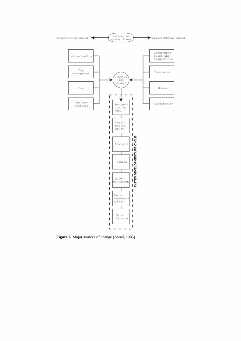
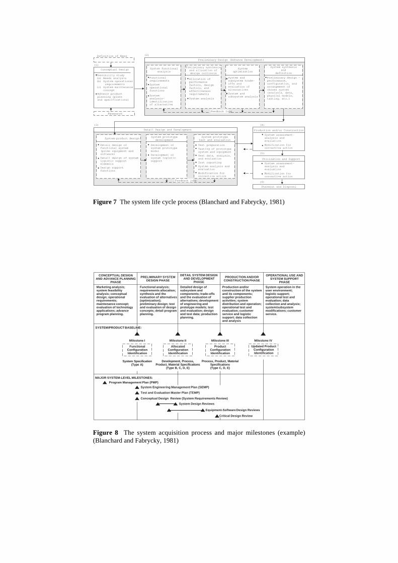
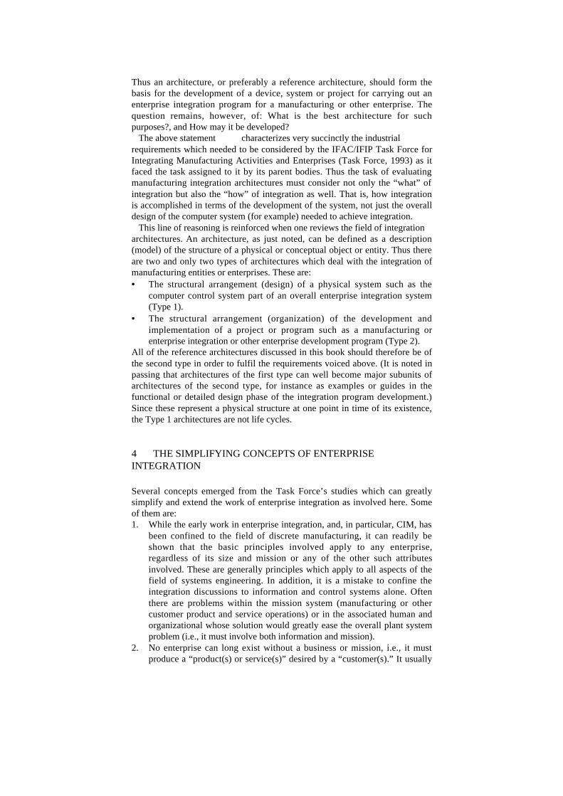
different designations are given for each of the separate phases. Likewise, thesame word or phrase can be used to describe very different activities from onelife cycle example to another. This is particularly true of the term“implementation” which may be used to mean “detailed design” or “theconstruction, installation and testing activities,” or it may even mean “thewhole process of converting a functional analysis to the final operationalsystem.” While the use of multiple terms does serve to better define and illustrate thesteps involved in each phase, particularly when the authors had differentspecific purposes for their writing, a precise, all encompassing set of standardterms is absolutely necessary if we are to ever achieve overall computer basedexecutability of enterprise systems or even enterprise integration itself. Besides the variations above, the life cycle diagrams are usually furtherelaborated to show various aspects of the methodology of carrying out theactual enterprise integration engineering project contemplated by the author(s).For example, that of Figure 6 particularly expands the topic of Recognition ofNeed by defining the various sources of Impetus for Change (Awad, 1985).Others greatly expand the sketch of the life cycle with branches and parallelpaths to model the proposed methodology in great detail. In this regard notethe diagrams of (Blanchard and Fabrycky, 1981) in Figures 7 and 8. It shouldbe noted that these latter two diagrams have been combined to form thediagram used extensively by the major international standards effort known asSTEP (STandard for the Exchange of Product Model Data) (ISO 10303) andparticularly the process industries branch (this effort known as PISTEP (STEPin the Process Industries). Other important elaborated forms are those proposed in the enterpriseintegration reference architectures studied by the IFAC/IFIP Task Force onArchitectures for Enterprise Integration (Task Force, 1993). Several of thesearchitectures are represented by chapters in the text as follows: CIMOSA(Kosanke and Vernadat), GRAI-GIM (Doumeingts, et al.), and PERA(Williams). It will be noted that the life cycle diagrams which represent the developmentof projects or programs are often called architectures in the literature. This isparticularly true in the enterprise integration field. As used in the context above, an architecture is any method (drawing, model,description, etc.) for giving the structure or framework showing theinterrelationship of all of the parts and/or functions of a device, system orenterprise. A reference architecture is a collection of the overall genericfunctions, descriptions, or behaviors of many (hopefully all) types of systemsand their associated structures or frameworks.
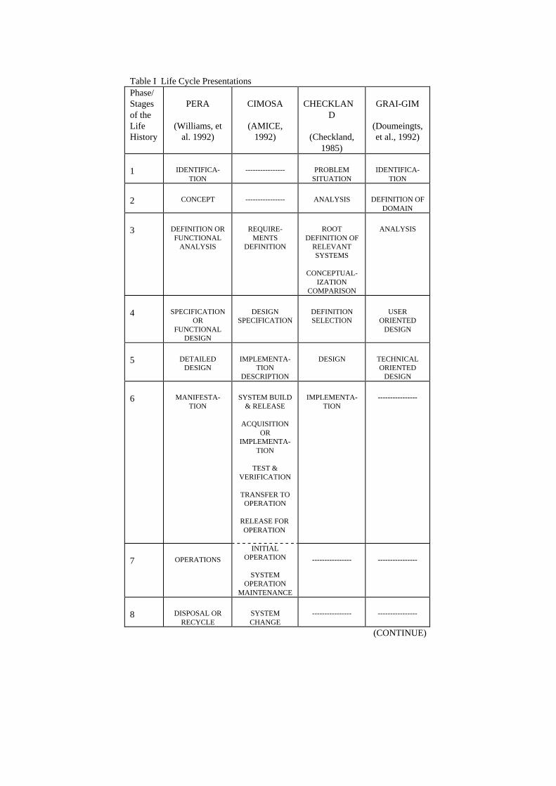
Table I Life Cycle PresentationsPhase/Stagesof theLifeHistory
PERA
(Williams, etal. 1992)
CIMOSA
(AMICE,1992)
CHECKLAND
(Checkland,1985)
GRAI-GIM
(Doumeingts,et al., 1992)
1 IDENTIFICA-TION
---------------- PROBLEMSITUATION
IDENTIFICA-TION
2 CONCEPT ---------------- ANALYSIS DEFINITION OFDOMAIN
3 DEFINITION ORFUNCTIONAL
ANALYSIS
REQUIRE-MENTS
DEFINITION
ROOTDEFINITION OF
RELEVANTSYSTEMS
CONCEPTUAL-IZATION
COMPARISON
ANALYSIS
4 SPECIFICATIONOR
FUNCTIONALDESIGN
DESIGNSPECIFICATION
DEFINITIONSELECTION
USERORIENTED
DESIGN
5 DETAILEDDESIGN
IMPLEMENTA-TION
DESCRIPTION
DESIGN TECHNICALORIENTED
DESIGN
6 MANIFESTA-TION
SYSTEM BUILD& RELEASE
ACQUISITIONOR
IMPLEMENTA-TION
TEST &VERIFICATION
TRANSFER TOOPERATION
RELEASE FOROPERATION
IMPLEMENTA-TION
----------------
7 OPERATIONS
INITIALOPERATION
SYSTEMOPERATION
MAINTENANCE
---------------- ----------------
8 DISPOSAL ORRECYCLE
SYSTEMCHANGE
---------------- ----------------
(CONTINUE)
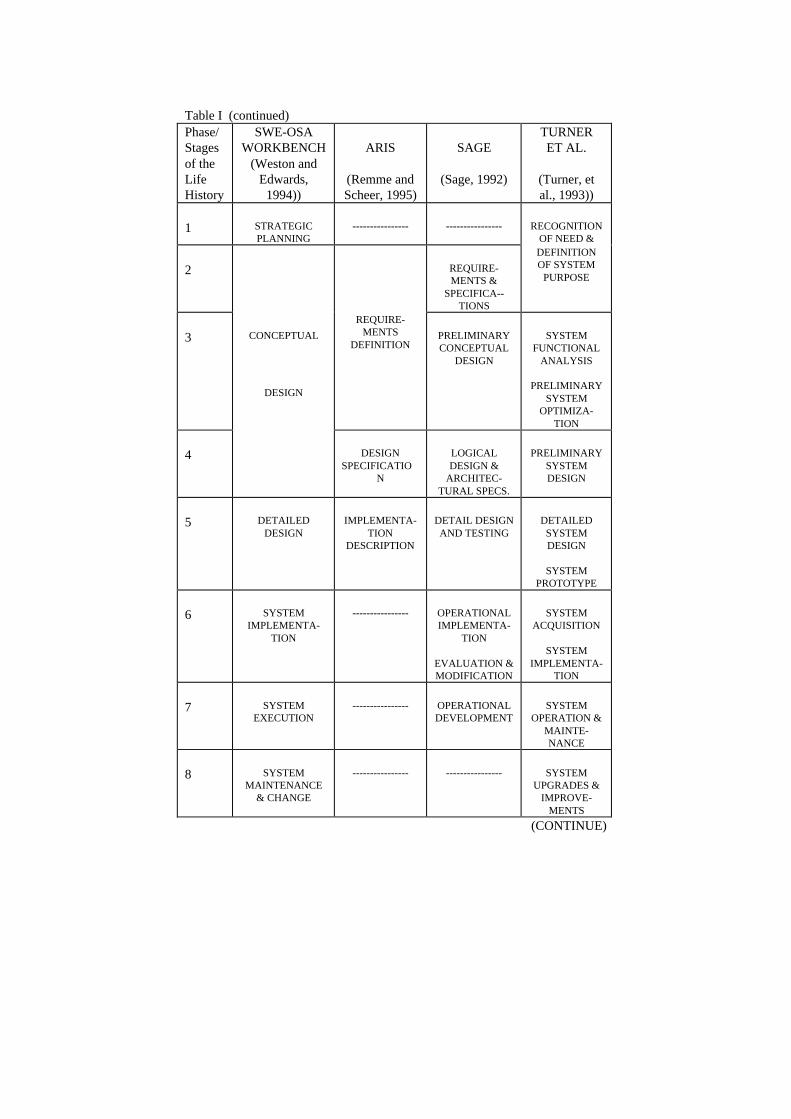
Table I (continued)Phase/Stagesof theLifeHistory
SWE-OSAWORKBENCH
(Weston andEdwards,
1994))
ARIS
(Remme andScheer, 1995)
SAGE
(Sage, 1992)
TURNERET AL.
(Turner, etal., 1993))
1 STRATEGICPLANNING
---------------- ---------------- RECOGNITIONOF NEED &
2 REQUIRE-MENTS &
SPECIFICA--TIONS
DEFINITIONOF SYSTEM
PURPOSE
3 CONCEPTUAL
DESIGN
REQUIRE-MENTS
DEFINITIONPRELIMINARYCONCEPTUAL
DESIGN
SYSTEMFUNCTIONAL
ANALYSIS
PRELIMINARYSYSTEM
OPTIMIZA-TION
4 DESIGNSPECIFICATIO
N
LOGICALDESIGN &
ARCHITEC-TURAL SPECS.
PRELIMINARYSYSTEMDESIGN
5 DETAILEDDESIGN
IMPLEMENTA-TION
DESCRIPTION
DETAIL DESIGNAND TESTING
DETAILEDSYSTEMDESIGN
SYSTEMPROTOTYPE
6 SYSTEMIMPLEMENTA-
TION
---------------- OPERATIONALIMPLEMENTA-
TION
EVALUATION &MODIFICATION
SYSTEMACQUISITION
SYSTEMIMPLEMENTA-
TION
7 SYSTEMEXECUTION
---------------- OPERATIONALDEVELOPMENT
SYSTEMOPERATION &
MAINTE-NANCE
8 SYSTEMMAINTENANCE
& CHANGE
---------------- ---------------- SYSTEMUPGRADES &
IMPROVE-MENTS
(CONTINUE)
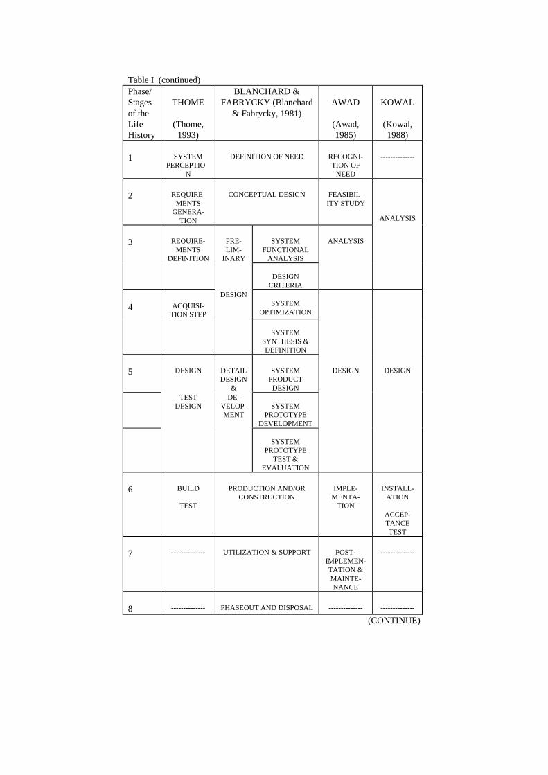
Table I (continued)Phase/Stagesof theLifeHistory
THOME
(Thome,1993)
BLANCHARD &FABRYCKY (Blanchard
& Fabrycky, 1981)AWAD
(Awad,1985)
KOWAL
(Kowal,1988)
1 SYSTEMPERCEPTIO
N
DEFINITION OF NEED RECOGNI-TION OF
NEED
--------------
2 REQUIRE-MENTS
GENERA-TION
CONCEPTUAL DESIGN FEASIBIL-ITY STUDY
ANALYSIS
3 REQUIRE-MENTS
DEFINITION
PRE-LIM-
INARY
SYSTEMFUNCTIONAL
ANALYSIS
ANALYSIS
DESIGNCRITERIA
4 ACQUISI-TION STEP
DESIGNSYSTEM
OPTIMIZATION
SYSTEMSYNTHESIS &DEFINITION
5 DESIGN DETAILDESIGN
&
SYSTEMPRODUCT
DESIGN
DESIGN DESIGN
TESTDESIGN
DE-VELOP-MENT
SYSTEMPROTOTYPE
DEVELOPMENT
SYSTEMPROTOTYPE
TEST &EVALUATION
6 BUILD
TEST
PRODUCTION AND/ORCONSTRUCTION
IMPLE-MENTA-
TION
INSTALL-ATION
ACCEP-TANCETEST
7 -------------- UTILIZATION & SUPPORT POST-IMPLEMEN-TATION &MAINTE-NANCE
--------------
8 -------------- PHASEOUT AND DISPOSAL -------------- --------------
(CONTINUE)
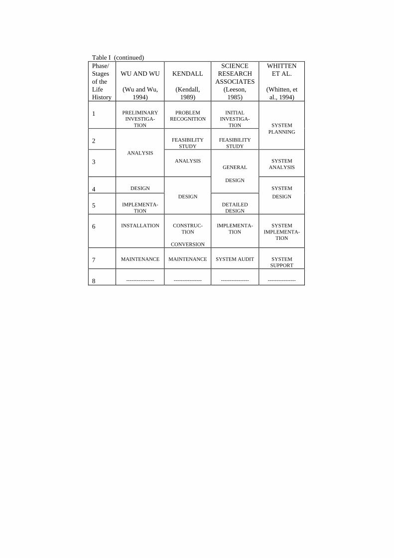
Table I (continued)Phase/Stagesof theLifeHistory
WU AND WU
(Wu and Wu,1994)
KENDALL
(Kendall,1989)
SCIENCERESEARCH
ASSOCIATES(Leeson,
1985)
WHITTENET AL.
(Whitten, etal., 1994)
1 PRELIMINARYINVESTIGA-
TION
PROBLEMRECOGNITION
INITIALINVESTIGA-
TION SYSTEM
2 FEASIBILITYSTUDY
FEASIBILITYSTUDY
PLANNING
3
ANALYSIS
ANALYSISGENERAL
SYSTEMANALYSIS
4 DESIGN
DESIGN
SYSTEM
5 IMPLEMENTA-TION
DESIGN
DETAILEDDESIGN
DESIGN
6 INSTALLATION CONSTRUC-TION
CONVERSION
IMPLEMENTA-TION
SYSTEMIMPLEMENTA-
TION
7 MAINTENANCE MAINTENANCE SYSTEM AUDIT SYSTEMSUPPORT
8 ---------------- ---------------- ---------------- ----------------
Organization-based Environmental-base d
SY
ST
EM
DE
VE
LOP
ME
NT
LIF
EC
YC
LE
Sources ofsystem ideas
Impetusfor
change
Governmentrules andregulations
Competition
Consumers
Union
Topmanagement
User
Systemsanalysis
Organization
Post-implemen-tation
Feasi-bilitystudy
Imple-mentation
Recogni-tion ofneed
Design
Main-tenance
Analysis
Figure 6 Major sources of change (Awad, 1985)
Development ofsystem prototypemodel
Development ofsystem logisticsupport
System prototypedevelopment
Test preparation
Testing of prototypesystem and equipment
Test data, analysis,and evaluation
Test reporting
System analysis andevaluation
Modification forcorrective action
System prototypetest and evaluation
Detail design offunctional system(prime equipment andsoftware)
Detail design of systemlogistic supportelements
Design supportfunctions
System-product design
Feedback loop
Detail Design and Development
Feedback loop
Preliminary Design (Advance Development)
Functionalrequirements
Systemoperationalfunctions
Systemanalysis-identificationof alternative
System functionalanalysis
Preliminary synthesisand allocation ofdesign critieria
Allocation ofperformancefactors, designfactors, andeffectivenessrequirements
System analysis
System synthesisand
definition
Preliminary design -performance,configuration, andarrangement ofchosen system(analysis, data,physical models,testing, etc.)
Systemoptimization
System andsubsystem trade-offs andevaluation ofalternatives
System andsubsystem analysis
Definition of Need
Conceptual Design
Feasibility study(a) Needs analysis(b) System operational
requirements(c) System maintenance
conceptAdvance productplanning (plansand specifications)
Research
Phaseout and Disposal
Production and/or Construction
System assessment-analysis andevaluation
Modification forcorrective action
Utilization and Support
System assessment-analysis andevaluation
Modification forcorrective action
(1)
(2)
(3) (4)
(5)
(6)
Figure 7 The system life cycle process (Blanchard and Fabrycky, 1981)
CONCEPTUAL DESIGNAND ADVANCE PLANNING
PHASE
PRELIMINARY SYSTEMDESIGN PHASE
DETAIL SYSTEM DESIGNAND DEVELOPMENT
PHASE
PRODUCTION AND/ORCONSTRUCTION PHASE
OPERATIONAL USE ANDSYSTEM SUPPORT
PHASE
Production and/orconstruction of the systemand its components;supplier productionactivities; systemdistribution and operation;operational test andevaluation; customerservice and logisticsupport; data collectionand analysis
Marketing analysis;system feasibilityanalysis; conceptualdesign; operationalrequirements;maintenance concept;evaluation of technologyapplications; advanceprogram planning.
Functional analysis;requirements allocation;synthesis and theevaluation of alternatives(optimization);preliminary design; testand evaluation of designconcepts; detail programplanning.
Detailed design ofsubsystem andcomponents; trade-offsand the evaluation ofalternatives; developmentof engineering andprototype models; testand evaluation; designand test data; productionplanning.
System operation in theuser environment;logistic support;operational test andevaluation; datacollection and analysis;system/subsystemmodifications; customerservice.
Milestone I Milestone II Milestone III Milestone IV
SYSTEM/PRODUCT BASELINE:
Updated ProductConfigurationIdentification
ProductConfigurationIdentification
AllocatedConfigurationIdentification
FunctionalConfigurationIdentification
MAJOR SYSTEM-LEVEL MILESTONES:
System Specification(Type A)
Development, Process,Product, Material Specifications
(Type B, C, D, E)
Process, Product, MaterialSpecifications(Type C, D, E)
Program Management Plan (PMP)
System Engineering Management Plan (SEMP)
Test and Evaluation Master Plan (TEMP)
Conceptual Design Review (System Requirements Review)
System Design Reviews
Equipment-Software Design Reviews
Critical Design Review
Figure 8 The system acquisition process and major milestones (example)(Blanchard and Fabrycky, 1981)
Thus an architecture, or preferably a reference architecture, should form thebasis for the development of a device, system or project for carrying out anenterprise integration program for a manufacturing or other enterprise. Thequestion remains, however, of: What is the best architecture for suchpurposes?, and How may it be developed? The above statement characterizes very succinctly the industrialrequirements which needed to be considered by the IFAC/IFIP Task Force forIntegrating Manufacturing Activities and Enterprises (Task Force, 1993) as itfaced the task assigned to it by its parent bodies. Thus the task of evaluatingmanufacturing integration architectures must consider not only the “what” ofintegration but also the “how” of integration as well. That is, how integrationis accomplished in terms of the development of the system, not just the overalldesign of the computer system (for example) needed to achieve integration. This line of reasoning is reinforced when one reviews the field of integrationarchitectures. An architecture, as just noted, can be defined as a description(model) of the structure of a physical or conceptual object or entity. Thus thereare two and only two types of architectures which deal with the integration ofmanufacturing entities or enterprises. These are:• The structural arrangement (design) of a physical system such as the
computer control system part of an overall enterprise integration system(Type 1).
• The structural arrangement (organization) of the development andimplementation of a project or program such as a manufacturing orenterprise integration or other enterprise development program (Type 2).
All of the reference architectures discussed in this book should therefore be ofthe second type in order to fulfil the requirements voiced above. (It is noted inpassing that architectures of the first type can well become major subunits ofarchitectures of the second type, for instance as examples or guides in thefunctional or detailed design phase of the integration program development.)Since these represent a physical structure at one point in time of its existence,the Type 1 architectures are not life cycles.
4 THE SIMPLIFYING CONCEPTS OF ENTERPRISEINTEGRATION
Several concepts emerged from the Task Force’s studies which can greatlysimplify and extend the work of enterprise integration as involved here. Someof them are:1. While the early work in enterprise integration, and, in particular, CIM, has
been confined to the field of discrete manufacturing, it can readily beshown that the basic principles involved apply to any enterprise,regardless of its size and mission or any of the other such attributesinvolved. These are generally principles which apply to all aspects of thefield of systems engineering. In addition, it is a mistake to confine theintegration discussions to information and control systems alone. Oftenthere are problems within the mission system (manufacturing or othercustomer product and service operations) or in the associated human andorganizational whose solution would greatly ease the overall plant systemproblem (i.e., it must involve both information and mission).
2. No enterprise can long exist without a business or mission, i.e., it mustproduce a “product(s) or service(s)” desired by a “customer(s).” It usually
must also produce these product(s) or service(s) in competition with otherenterprises also vying for this same business.
3. There are only two basic classes of functions involved in operating anyenterprise:a) Those involved in operating the “processes”* which result in
producing the “product” which fulfills the enterprise’s mission, i.e.,the customer product or service business in which the enterprise isengaged. In the manufacturing plant these would include all materialand energy transformation type tasks and the movement and storageof the same materials, energy, goods in process and products.
b) Those involved in the “control” of the mission in an “optimal”manner to achieve the necessary economic or other gains whichassure the viability or continued successful existence of theenterprise. These comprise the collection, storage and use (i.e.,transformations) of information concerning the business processes inorder to control them, i.e., to develop and apply necessary changes tothe business processes to achieve and maintain their required“optimal” operation. Thus it includes all planning, scheduling,control, data management, etc., functions.
4. Normally, information or data will undergo multiple transformations, i.e.,many separate tasks (where a task defines each transformation) infulfilling the information-handling requirements for an enterprise or CIMsystem. These transformations or tasks are usually successive operationsforming sets of sequential and parallel networks.
5. The same is true of the material and energy transformation tasks forfulfilling the physical production or plant operations requirements for theenterprise.
6. In each case the networks involved can be combined, if desired, to achieveone major network of each type (Informational Transformations orMaterial and Energy Transformations, respectively), the totality of whichdefines the functionality of the enterprise or other business entity beingconsidered (i.e., the totality of the information network, plus themanufacturing networks, both of which can be developed separately butused conjointly).
7. The two networks interface in those tasks that develop operating variablestate or status from the manufacturing processes (sensors) and those thatdeliver operational commands to the operational units (actuators andrelated devices). Except for these tasks and their related requirements,which do affect the other networks, each network can be developedindependently of the other.
8. Initial functional analysis or general study of either or both classes offunctions above can be carried out without knowledge or concern of howthey will ultimately be implemented in the operating enterprise.
9. For many technological, economic, and social reasons, humans areinvolved in the implementation and execution of many business processesof all types in both classes above. Others, of course, may possibly beautomated or mechanized. Thus there must be three classes ofimplemented tasks or business processes:
* The use of quotation marks on several of the terms used here indicates they are defined in the
most general manner possible in order to cover the extremely wide range of aims, methodsand conditions covered.
a) Those of the information and control type which can be “automated”by computers or other “control” devices.
b) Those of the mission tasks or business processes which can beautomated by the “mission fulfillment” equipment.
c) Those functions carried out by humans, whether of the control ormission fulfillment class.
There must be a simple way of showing where and how the human fits inthe enterprise and how the distribution of functions between humans andmachines is accomplished.
10. All enterprises, of whatever type, follow a “life cycle” from their initialconcept in the mind of an entrepreneur through a series of stages or phasescomprising their development, design, construction, operation andmaintenance, refurbishment or obsolescence, and final disposal.
11. Not only does this life cycle apply to the enterprise but also to theenterprises’ products as well. Thus, carried further, one enterprise can bethe product of another. For example, a construction enterprise could builda manufacturing plant (enterprise) as its product. The manufacturing plantwould then manufacture (produce) its own product, such as anautomobile. The automobile also has its own life cycle, which goesthrough similar steps to those discussed here
12. Once the integration of all of the informational and customer product andservice functions of an enterprise have been properly planned (the MasterPlan), the actual implementation of such an integration may be broken upinto a series of coordinated projects, any and all of which are within thefinancial, physical, and economic capabilities of the enterprise, which canbe carried out as these resources allow as long as the requirements of theMaster Plan are followed. When these projects are completed, theintegration desired will be complete.
13. All tasks should be defined in a modular fashion, along with their requiredinterconnections, so they may later be interchanged with other tasks thatcarry out similar functions but in a different manner should this bedesirable.
14. Likewise, these latter tasks should also be implemented in a modularfashion, again permitting their later substitution by still other differentmethods of carrying out the same function. The choice of theseimplementation methods can be governed by independent design andoptimization techniques as long as the task specifications are honored.
15. Provided the modular implementation just noted is used, theinterconnections between these modules can be considered interfaces. Ifthese interfaces are specified and implemented using company, industry,national and/or internationally agreed upon standards, the interchange andsubstitution noted in Items 13 and 14 will be greatly facilitated.
16. A diagram or other representation describing the interrelationship of allthe tasks, networks, and processes noted above, all arranged in theirproper place in the several phases of the development or life cycle of theenterprise, can be called an Architecture. This since the resulting diagramshows the project structure of the overall set of tasks for developing andusing the enterprise. As noted in the text these architectures can be calledType 2 architectures to distinguish them from those architecturesdescribing the physical structure of a system at one point in time. Theselatter we have called Type 1.
17. By considering that manufacturing is a type of customer service, i.e.,production of goods for purchase by the customer, and then expanding the
definition of customer service to include all possible goods and servicesthe enterprise may render to the customer, we can expand the applicabilityof the Architecture to cover all possible types of enterprises. Thus themission execution side of the Architecture would then represent thecustomer service rendered by any enterprise even if that service itselfinvolved the supplying of information type products to the customer.
These concepts then form the basis for developing an architecture and itsassociated methodology needed for carrying out enterprise integrationengineering tasks as conceived by the Task Force and its members.
5 RECURSION IN THE USE OF THE LIFE CYCLE
Recursion in the use of the life cycle can occur in two forms. First, thegeneration form in the sense that one enterprise can produce another, etc., forseveral generations and each enterprise in turn can be represented by a lifecycle. Second, the hierarchical form, in that each system can be divided intosubsystems, through a series of subdivisions, and each subsystem can in turnbe shown to have a life cycle, in fact the same life cycle. Bernus and Nemes in their definition of GERAM (Bernus and Nemes, 1994)for the IFAC/IFIP Task Force on Enterprise Integration (Task Force, 1993)have defined four classes of enterprises in the generational sense as follows:1. The Strategic Enterprise Management Process Life Cycle, which defines
as a product;2. The Enterprise Engineering/Integration Process Life Cycle Methodology
(Life Cycle in short) which produces;3. The Manufacturing Enterprise Life Cycle which produces;4. The final Product Life Cycle for the product to go to the final customer. The life cycle of each entity (product) in turn is brought about by theoperation (Operation Phase) of the entity above it, i.e., when the enterpriseoperates, it brings about the life cycle of the product below it. A discussion in the chapter on PERA in this text shows how the PERAArchitecture (a life cycle representation) can illustrate the above concept.Likewise the chapter on GERAM (Bernus and Nemes, this text) expands onthe generational concept mentioned above.
5.1 Activities Within Each Phase of the Life Cycle
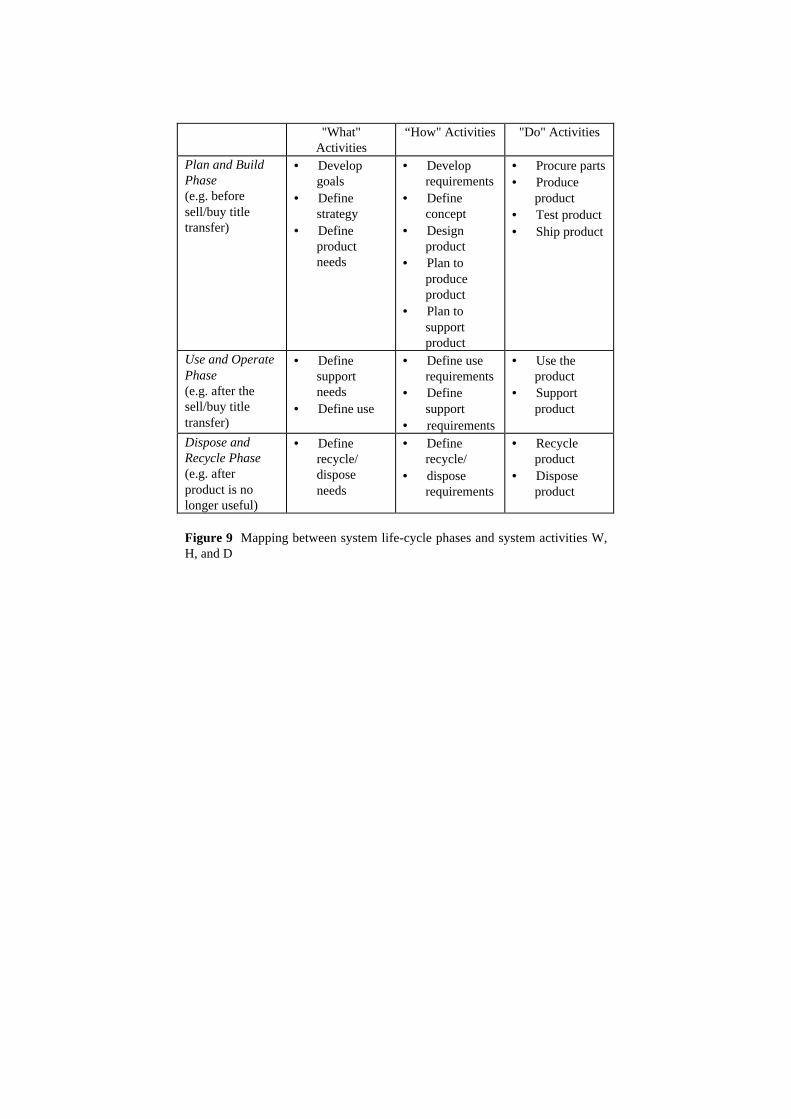
Recursiveness can also be shown with each phase of the life cycle (ISO, 1997)by using the following simple set of aggregated activities. Three types of activities are required to solve issues found within each high-level system life cycle phase (Plan/Build, Use/Operate, Recycle/Dispose).These types are• find out what to do (W Activity),• find out how to do it (H Activity),• do it (D Activity).Figure 9 illustrates an example for a manufactured product, showing amapping between common names for system life cycle phases and the what,how, and do activities. The sketch of Figure 2 also shows a similarrelationship.
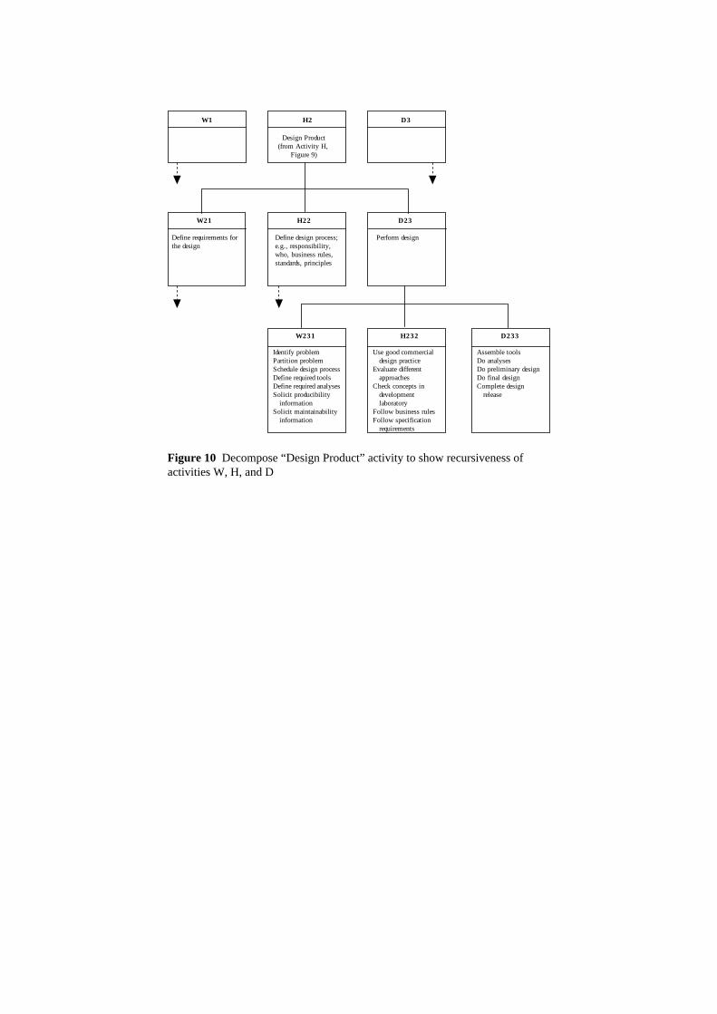
W, H and D activities are recursive and decomposable. Therefore, eachactivity can be divided into subactivities, and these subactivities will consist ofanother set of W, H and D activities (see Figure 10). These subactivities may be represented by different types of models ordescriptions. These models shall be able to interoperate where it has beendetermined that these subactivities need to communicate with each other. Example: In a manufacturing enterprise, the activity “Produce” can be, inturn, separated into lower-level W, H and D activities. W activities are user-needs driven and comprise any activities finally resulting in a request for whatis to be produced. H activities are technology-requirements driven andcomprise any activities finally resulting in how the product/system has to beproduced in terms of a release statement. D activities are task driven andcomprise any activities finally resulting in the shipment of the product.
5.2 Iteration
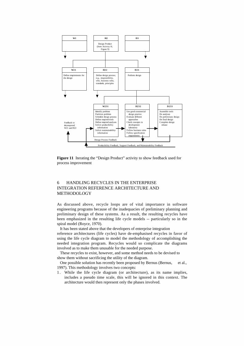
Activities W, H and D are iterative; therefore, there is no fixed sequence ofthese activities, but it is possible to return to previous activities to repeat themwith updated input (see Figure 11). Each performance of each activity may result in a different model. Every oneof these different models shall be subject to both change and versionmanagement.
"What"Activities
“How" Activities "Do" Activities
Plan and BuildPhase(e.g. beforesell/buy titletransfer)
• Developgoals
• Definestrategy
• Defineproductneeds
• Developrequirements
• Defineconcept
• Designproduct
• Plan toproduceproduct
• Plan tosupportproduct
• Procure parts• Produce
product• Test product• Ship product
Use and OperatePhase(e.g. after thesell/buy titletransfer)
• Definesupportneeds
• Define use
• Define userequirements
• Definesupport
• requirements
• Use theproduct
• Supportproduct
Dispose andRecycle Phase(e.g. afterproduct is nolonger useful)
• Definerecycle/disposeneeds
• Definerecycle/
• disposerequirements
• Recycleproduct
• Disposeproduct
Figure 9 Mapping between system life-cycle phases and system activities W,H, and D
W1
W21
W231
H2 D3
H22 D23
H232 D233
Design Product(from Activity H,
Figure 9)
Define requirements for the design
Define design process; e.g., responsibility, who, business rules, standards, principles
Perform design
Identify problemPartition problemSchedule design processDefine required toolsDefine required analysesSolicit producibility informationSolicit maintainability information
Use good commercial design practiceEvaluate different approachesCheck concepts in development laboratoryFollow business rulesFollow specification requirements
Assemble toolsDo analysesDo preliminary designDo final designComplete design release
Figure 10 Decompose “Design Product” activity to show recursiveness ofactivities W, H, and D
W1
W21
W231
H2 D3
H22 D23
H232 D233
Design Product(from Activity H,
Figure 9)
Define requirements for the design
Define design process; e.g., responsibility, who, business rules, standards, principles
Perform design
Identify problemPartition problemSchedule design processDefine required toolsDefine required analysesSolicit producibility informationSolicit maintainability information
Use good commercial design practiceEvaluate different approachesCheck concepts in development laboratoryFollow business rulesFollow specification requirements
Assemble toolsDo analysesDo preliminary designDo final designComplete design release
Feedback to decomposed W21 and H22
Design Process Feedback
Producibility Feedback, Support Feedback, and Maintainability Feedback
Figure 11 Iterating the “Design Product” activity to show feedback used forprocess improvement
6 HANDLING RECYCLES IN THE ENTERPRISEINTEGRATION REFERENCE ARCHITECTURE ANDMETHODOLOGY
As discussed above, recycle loops are of vital importance in softwareengineering programs because of the inadequacies of preliminary planning andpreliminary design of these systems. As a result, the resulting recycles havebeen emphasized in the resulting life cycle models -- particularly so in thespiral model (Royce, 1970). It has been stated above that the developers of enterprise integrationreference architectures (life cycles) have de-emphasised recycles in favor ofusing the life cycle diagram to model the methodology of accomplishing theneeded integration program. Recycles would so complicate the diagramsinvolved as to make them unusable for the needed purpose. These recycles to exist, however, and some method needs to be devised toshow them without sacrificing the utility of the diagram. One possible solution has recently been proposed by Bernus (Bernus, et al.,1997). This methodology involves two concepts:1 . While the life cycle diagram (or architecture), as its name implies,
includes a pseudo time scale, this will be ignored in this context. Thearchitecture would then represent only the phases involved.
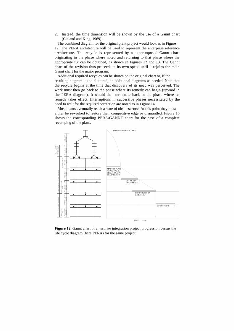
2. Instead, the time dimension will be shown by the use of a Gannt chart(Cleland and King, 1969).
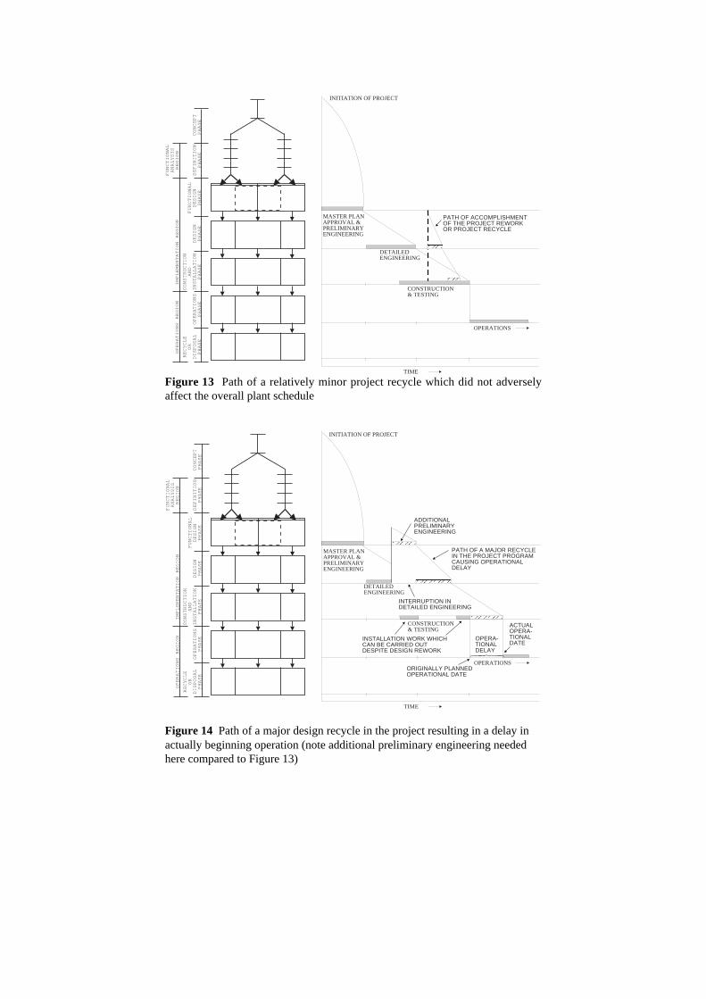
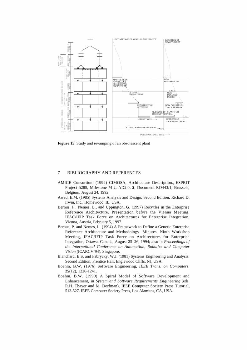
The combined diagram for the original plant project would look as in Figure12. The PERA architecture will be used to represent the enterprise referencearchitecture. The recycle is represented by a superimposed Gannt chartoriginating in the phase where noted and returning to that phase where theappropriate fix can be obtained, as shown in Figures 12 and 13. The Ganntchart of the revision thus proceeds at its own speed until it rejoins the mainGannt chart for the major program. Additional required recycles can be shown on the original chart or, if theresulting diagram is too cluttered, on additional diagrams as needed. Note thatthe recycle begins at the time that discovery of its need was perceived. Thework must then go back to the phase where its remedy can begin (upward inthe PERA diagram). It would then terminate back in the phase where itsremedy takes effect. Interruptions in successive phases necessitated by theneed to wait for the required correction are noted as in Figure 14. Most plants eventually reach a state of obsolescence. At this point they musteither be reworked to restore their competitive edge or dismantled. Figure 15shows the corresponding PERA/GANNT chart for the case of a completerevamping of the plant.
CO
NS
TR
UC
TIO
NA
ND
INS
TA
LL
AT
ION
PH
AS
EO
PE
RA
TIO
NS
PH
AS
E
OP
ER
AT
ION
SR
EG
ION
DE
SIG
NP
HA
SE
FU
NC
TIO
NA
LD
ES
IGN
PH
AS
ED
EF
INIT
ION
PH
AS
EC
ON
CE
PT
PH
AS
E
FU
NC
TIO
NA
LA
NA
LY
SIS
RE
GIO
NIM
PL
EM
EN
TA
TIO
NR
EG
ION
RE
CY
CL
EO
RD
ISP
OS
AL
PH
AS
E
TIME
INITIATION OF PROJECT
DETAILEDENGINEERING
CONSTRUCTION& TESTING
OPERATIONS
MASTER PLANAPPROVAL &PRELIMINARYENGINEERING
Figure 12 Gannt chart of enterprise integration project progression versus thelife cycle diagram (here PERA) for the same project
CO
NS
TR
UC
TIO
NA
ND
INS
TA
LL
AT
ION
PH
AS
EO
PE
RA
TIO
NS
PH
AS
E
OP
ER
AT
ION
SR
EG
ION
DE
SIG
NP
HA
SE
FU
NC
TIO
NA
LD
ES
IGN
PH
AS
ED
EF
INIT
ION
PH
AS
EC
ON
CE
PT
PH
AS
E
FU
NC
TIO
NA
LA
NA
LY
SIS
RE
GIO
NIM
PL
EM
EN
TA
TIO
NR
EG
ION
RE
CY
CL
EO
RD
ISP
OS
AL
PH
AS
E
TIME
INITIATION OF PROJECT
DETAILEDENGINEERING
CONSTRUCTION& TESTING
OPERATIONS
MASTER PLANAPPROVAL &PRELIMINARYENGINEERING
PATH OF ACCOMPLISHMENTOF THE PROJECT REWORKOR PROJECT RECYCLE
Figure 13 Path of a relatively minor project recycle which did not adverselyaffect the overall plant schedule
CO
NS
TR
UC
TIO
NA
ND
INS
TA
LL
AT
ION
PH
AS
EO
PE
RA
TIO
NS
PH
AS
E
OP
ER
AT
ION
SR
EG
ION
DE
SIG
NP
HA
SE
FU
NC
TIO
NA
LD
ES
IGN
PH
AS
ED
EF
INIT
ION
PH
AS
EC
ON
CE
PT
PH
AS
E
FU
NC
TIO
NA
LA
NA
LY
SIS
RE
GIO
NIM
PL
EM
EN
TA
TIO
NR
EG
ION
RE
CY
CL
EO
RD
ISP
OS
AL
PH
AS
E
TIME
DETAILEDENGINEERING
CONSTRUCTION& TESTING
OPERATIONS
MASTER PLANAPPROVAL &PRELIMINARYENGINEERING
PATH OF A MAJOR RECYCLEIN THE PROJECT PROGRAMCAUSING OPERATIONALDELAY
ADDITIONALPRELIMINARYENGINEERING
OPERA-TIONALDELAY
ACTUALOPERA-TIONALDATE
ORIGINALLY PLANNEDOPERATIONAL DATE
INTERRUPTION INDETAILED ENGINEERING
INSTALLATION WORK WHICHCAN BE CARRIED OUTDESPITE DESIGN REWORK
INITIATION OF PROJECT
Figure 14 Path of a major design recycle in the project resulting in a delay inactually beginning operation (note additional preliminary engineering neededhere compared to Figure 13)
CO
NS
TR
UC
TIO
NA
ND
INS
TA
LL
AT
ION
PH
AS
EO
PE
RA
TIO
NS
PH
AS
E
OP
ER
AT
ION
SR
EG
ION
DE
SIG
NP
HA
SE
FU
NC
TIO
NA
LD
ES
IGN
PH
AS
ED
EF
INIT
ION
PH
AS
EC
ON
CE
PT
PH
AS
E
FU
NC
TIO
NA
LA
NA
LY
SIS
RE
GIO
NIM
PL
EM
EN
TA
TIO
NR
EG
ION
RE
CY
CL
EO
RD
ISP
OS
AL
PH
AS
E
FORESHORTENED TIME
INITIATION OF ORIGINAL PLANT PROJECT
DETAILEDENGINEERING
CONSTRUCTION& TESTING
OPERATIONS OPERATIONS
MASTER PLANAPPROVAL &PRELIMINARYENGINEERING
NEWDETAILEDDESIGN
NEW CONSTRUC-TION & TESTING
CLOSURE OF PLANT FORRECONSTRUCTION
OF REVISED PLANT
STUDY OF FUTURE OF PLANT
NEWMASTER PLAN
INITIATION OFNEW PROJECT
Figure 15 Study and revamping of an obsolescent plant
7 BIBLIOGRAPHY AND REFERENCES
AMICE Consortium (1992) CIMOSA, Architecture Description., ESPRITProject 5288, Milestone M-2, AD2.0, 2, Document RO443/1, Brussels,Belgium, August 24, 1992.
Awad, E.M. (1985) Systems Analysis and Design. Second Edition, Richard D.Irwin, Inc., Homewood, IL, USA.
Bernus, P., Nemes, L., and Uppington, G. (1997) Recycles in the EnterpriseReference Architecture. Presentation before the Vienna Meeting,IFAC/IFIP Task Force on Architectures for Enterprise Integration,Vienna, Austria, February 5, 1997.
Bernus, P. and Nemes, L. (1994) A Framework to Define a Generic EnterpriseReference Architecture and Methodology. Minutes, Ninth WorkshopMeeting, IFAC/IFIP Task Force on Architectures for EnterpriseIntegration, Ottawa, Canada, August 25–26, 1994; also in Proceedings ofthe International Conference on Automation, Robotics and ComputerVision (ICARCV’94), Singapore.
Blanchard, B.S. and Fabrycky, W.J. (1981) Systems Engineering and Analysis.Second Edition, Prentice Hall, Englewood Cliffs, NJ, USA.
Boehm, B.W. (1976) Software Engineering, IEEE Trans. on Computers,25(12), 1226-1241.
Boehm, B.W. (1990) A Spiral Model of Software Development andEnhancement, in System and Software Requirements Engineering (eds.R.H. Thayer and M. Dorfman), IEEE Computer Society Press Tutorial,513-527. IEEE Computer Society Press, Los Alamitos, CA, USA.
Brown, J., Sackett, P., and Wortman, H. (1995) Industry Requirements andAssociated Research Issues in the Extended Enterprise, in IntegratedManufacturing Systems Engineering (eds. Pierre Ladet and FrancoisVernadat), Chapman and Hall, London, UK.
Checkland, P.B. (1985) Towards a Systems Based Methodology for Real-World Problem Solving, in Systems Behaviour (ed. Open System Group),Third Edition, Harper & Row, Publishers, London, UK.
Cleland, D.I. and King, W.R. (1969) Systems, Organizations, Analysis,Management. McGraw-Hill, New York, NY, USA.
Doumeingts, G., Vallespir, B., Zanettin, M., and Chen, D. (1992) GRAI-GIMIntegrated Methodology, A Methodology for Designing CIM Systems,Version 1.0. LAP/GRAI, University Bordeaux I, France.
Hall, A.D. (1962) A Methodology for Systems Engineering. D. Van Nostrandand Company, New York, NY, USA.
IFAC/IFIP Task Force on Architectures for Integrating ManufacturingActivities and Enterprises (1993) Architectures for IntegratingManufacturing Activities and Enterprises, (ed. T.J. Williams), TechnicalReport, Purdue Laboratory of Applied Industrial Control, PurdueUniversity, West Lafayette, IN, USA. Also published as: Williams, T.J.,Bernus, P., Brosvic, J., Chen, D., Doumeingts, G., Nemes, L., Nevins,J.L., Vlietstra, J., Zoetekouw, D., and with the contributions of othermembers of the IFAC/IFIP Task Force on Architectures for IntegratingManufacturing Activities and Enterprises, Architectures for IntegratingManufacturing Activities and Enterprises. The 12th IFAC WorldCongress, Sydney, Australia (July 19-23, 1993); same authors and sametitle (1994), Computers in Industry, 24(2-3), 111-140, and Control Eng.Practice, 2(6), 939-960, and as Bernus, P., Nemes, L., and Williams, T.J.(1996), Architectures for Enterprise Integration, Chapman and Hall,London.
ISO/TC184/SC5 (January 1997) Industrial Automation Systems - Conceptsand Rules for Enterprise Models. DIS 14258.
Kendall, P.A. (1989) Introduction to Systems Analysis and Design: AStructured Approach. Second Edition, William C. Brown, Publishers,Dubuque, IA, USA.
Kowal, J. A. (1988) Analyzing Systems, Prentice Hall, Englewood Cliffs, NJ.Leeson, M. (1985) Systems Analysis and Design. Second Edition, Science
Research Associates, Inc., Chicago, IL, USA.Machol, R.E. (1965) (ed.) Systems Engineering Handbook. McGraw-Hill
Book Company, New York, NY, USA.Rathwell, G.A., and Williams, T.J. (1996) Use of the Purdue Enterprise
Reference Architecture and Methodology in Industry (the Fluor DanielExample), in Modeling and Methodologies for Enterprise Integration(eds. P. Bernus and L. Nemes), Chapman and Hall, London.
Remme, M. and Scheer, A.W. (1995) Planning Centers — New Conceptionfor Re-Engineering Activities in Non-Producing Areas, in Proceedings ofReengineering the Enterprise, Galway, Ireland, April 20–21, 1995, 1–9.
Royce, W.W. (August 1970) Managing the Development of Large SoftwareSystems: Concept and Techniques, Proceedings WESCON, AIEE.
Sage, A.P. (1992) Systems Engineering. John Wiley and Sons, Inc., NewYork, NY, USA.
Thomé, B. (ed.) (1993) Systems Engineering, Principles and Practice ofComputer-Based Systems Engineering. John Wiley & Sons, Inc., NewYork, NY, USA.
Turner, W.C., Mize, J.H., Case, K.E., and Nasemetz, J.W. (1993) Introductionto Industrial and Systems Engineering. Third Edition, Prentice Hall,Englewood Cliffs, NJ, USA.
Weston, R.H. and Edwards, J.M. (1994) A Model-Driven Toolset for FlexiblyIntegrated Manufacturing Systems. Proceedings of European Workshopon Integrated Manufacturing Systems Engineering, Grenoble, France,December 12–14, 1994, 441–450.
Whitten, J.L., Bentley, L.D., and Barlow, V.M. (1994) Systems Analysis andDesign Methods. Third Edition, Richard D. Irwin, Inc., Burr Ridge, IL,USA.
Williams, T.J. (1961) Systems Engineering for the Process Industries.McGraw-Hill Book Company, New York, NY, USA.
Williams, T.J., and the Members of the Industry-Purdue UniversityConsortium for CIM (1991) The P u r d u e Enterprise ReferenceArchitecture. Technical Report 154, Purdue Laboratory for AppliedIndustrial Control, Purdue University, West Lafayette, IN, USA. Alsopublished as: Williams, T.J. (1992), The Purdue Enterprise ReferenceArchitecture, Instrument Society of America, Research Triangle Park, NC,USA.
Wu, S.Y. and Wu, M.S. (1994) Systems Analysis and Design. West PublishingCompany, St Paul, MN, USA.
8 BIOGRAPHIES
Theodore J. Williams is Professor Emeritus of Engineering and DirectorEmeritus of the Purdue Laboratory for Applied Industrial Control, PurdueUniversity, West Lafayette, Indiana, USA. He was the Founding Chairman ofthe IFAC/IFIP Task Force on Architectures for Enterprise Integration. He wasalso the Founding Chairman of IFIP Technical Committee TC-5, ComputerApplications in Technology. He is a Past-President of the Instrument Societyof America, of the American Automatic Control Council and of the AmericanFederation of Information Processing Societies.
Hong Li is currently pursuing the MBA Program at the University ofPittsburgh. Dr. Li received his Ph.D. in industrial engineering from PurdueUniversity, West Lafayette, Indiana, USA, in December 1994. He received hisMS in systems engineering from the University of Science and Technology ofBeijing, China before coming to the United States. His research interests areenterprise reference architectures and methodologies and their application inindustry, and production planning and scheduling.
Peter Bernus leads the Enterprise Integration Group at the School ofComputing and Information Technology, Griffith University, Australia, and iscurrently chair of the IFIP/IFAC Task Force on Enterprise IntegrationArchitectures, as well as IFIP WG5.12 and IFAC TC MIA. Dr. Bernus hasedited two books, two special issues of journals, and wrote over 40 articles inthe area of Enterprise Integration. He works as a researcher and consultant; hisinterests include Enterprise Engineering and Enterprise Modelling, ReferenceArchitectures, and generally the management of change in the enterprise,Human-computer Interaction, and the application of AI and databasetechniques in the area of enterprise integration.
Greg Uppington is a PhD candidate at Griffith University and is working onenterprise integration methodologies applied to the service and manufacturingsectors. His main interests are the management of change in the enterpriseintegration process and the relationship between formal and informal processesin strategy formulation. Mr. Uppington has a degree in Information Systemswith Honours and is member of the Enterprise Integration Group and the IMSGlobeman 21 team at Griffith University, Brisbane, Australia.
Laszlo Nemes is a Chief Research Scientist at the Commonwealth Scientificand Industrial Research Organisation, Australia, leading the IntelligentManufacturing Research Program. He is on the Board of Directors for the Co-operative Research Centre for Intelligent Manufacturing Systems. Dr. Nemeshas published 85 papers and holds 6 patents. He is a member of EditorialBoards for three technical journals. Dr. Nemes is a Fellow of the IEAust, andISPE.