Embed Size (px)
Citation preview

The LHC Reflectometer:The LHC Reflectometer:Obstacle Detection in the Obstacle Detection in the
LHC Beam ScreenLHC Beam Screen
Tom Kroyer, CERN AB-RF
Krakow Workshop, 17.06.2004www.cern.ch/tkroyer/reflec

17.06.2004 Krakow Workshop T.Kroyer: Obstacle detection in the LHC beam screen... 2
MotivationMotivation
In certain accelerators strange objects were found…How to locate them without using the beam???
17.06.2004 Krakow Workshop T.Kroyer: Obstacle detection in the LHC beam screen... 3
Waveguide Mode Time Waveguide Mode Time Domain ReflectometryDomain Reflectometry
Waveguide mode time domain reflectromety(TDR) has been used for more than 20 years to locate undesired deformations on long waveguides in telecommunication towersIt was used at ESRF to locate discontinuities in their vacuum chamber during assembly.

17.06.2004 Krakow Workshop T.Kroyer: Obstacle detection in the LHC beam screen... 4
Synthetic pulse TDRSynthetic pulse TDR
A state-of-the-art vector network analyzer (VNA) can be usedAll parameters can be well controlled => good reproducibility and wide range of settingsWaveguide calibration and dispersion compensation is possibleHigh dynamic range due to frequency domain measurement
All measurements are done in the frequency domain, conversion to time domain by FFT
Avantages:

17.06.2004 Krakow Workshop T.Kroyer: Obstacle detection in the LHC beam screen... 5
On the LHC beam screen, waveguide modes propagate in the microwave frequency range.Two modes were found to be suitable for reflectometer operation:
Waveguide modes on the beam screenWaveguide modes on the beam screen
The first TE mode: TEc11cut-off frequency: 3.6 GHzTransverse E field pattern:
The first TM mode: TE01cut-off frequency: 5.3 GHzTransverse H field pattern:

17.06.2004 Krakow Workshop T.Kroyer: Obstacle detection in the LHC beam screen... 6
Challenges of waveguide mode Challenges of waveguide mode TDR on the beam screenTDR on the beam screen
Attenuation: limits the range of the reflectometer => high dynamic range of the VNA is indispensable (more than 100 dB!)Waveguide dispersion => step-by-step “focusing” to short sections requiredHigher order waveguide mode can propagate => Mode Mixing can occurMultiple reflections by interconnects: Can we look through 50 or more interconnects?

17.06.2004 Krakow Workshop T.Kroyer: Obstacle detection in the LHC beam screen... 7
Estimation of rangeEstimation of range
The dynamic range of the current VNA of about 120 dB for S11
The total attenuation at room temperature (including interconnects) is expected to be smaller than 0.07 dB/m for both TE and TM modeThe smallest obstacle to be found (M3 nut size) should give a reflection of -40 dB
⇒ attenuation budget: 80 dB⇒ one-way attenuation budget: 40 dB⇒ range: 600 m

17.06.2004 Krakow Workshop T.Kroyer: Obstacle detection in the LHC beam screen... 8
Dispersion compensationDispersion compensation
Example: 50 m test track of beam screen without cold boreInterconnects close to 15 m and 30 mMeasurement with TM01 mode
0 10 20 30 40 50-100
-90
-80
-70
-60
-50
-40
-30
-20
-10
length on line [m]
S 11 [d
B]
raw datafocused data

17.06.2004 Krakow Workshop T.Kroyer: Obstacle detection in the LHC beam screen... 9
Mode Mode Mixing (1)Mixing (1)
Good news: was not observed!
2 possible reasons:
Very good mode excitationIt simply does not occur
Check: data was focused for “bad” mode if this mode is present, additional peak should become visible
17.06.2004 Krakow Workshop T.Kroyer: Obstacle detection in the LHC beam screen... 10
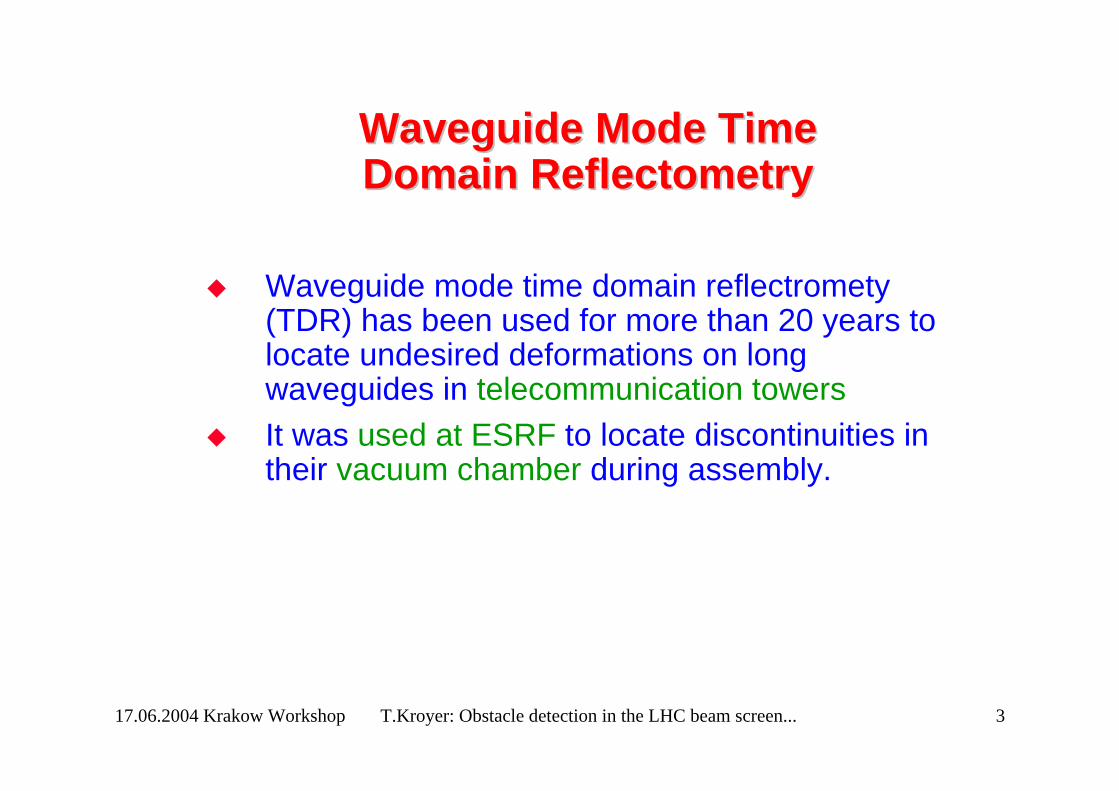
Mode Mode Mixing (2)Mixing (2)What it would look like: Bad excitation of second TE mode, first TE mode appears:

17.06.2004 Krakow Workshop T.Kroyer: Obstacle detection in the LHC beam screen... 11
The Measurement EquipmentThe Measurement EquipmentModern network analyser (Agilent E8358x)Notebook for number crunching (optional)Two kind of mode launchers, one for each mode usedSignal processing and data archiving software

17.06.2004 Krakow Workshop T.Kroyer: Obstacle detection in the LHC beam screen... 12
Prototypes of the Mode LaunchersPrototypes of the Mode Launchers
TM01 mode TWc11 mode

17.06.2004 Krakow Workshop T.Kroyer: Obstacle detection in the LHC beam screen... 13
TETE1010 mode launchermode launcher
Flat waveguide necessary for a spurious mode-free excitation=> Use commercial C-band coax to waveguide junction to excite rectangular TE10 mode (nominal frequency range: 3.95 to 5.85GHz)
Transition to TEc11 in beam-pipe (with the index c for cosine defining the polarization of the electric field for the TE11 mode being vertical)-23 dB reflection averaged over the frequency range of interest
Resistive absorbant foil for undesired mode suppression can be inserted here

17.06.2004 Krakow Workshop T.Kroyer: Obstacle detection in the LHC beam screen... 14
TMTM0101 mode launchermode launcher
Conversion from TEM mode on 50 Ω coax line into TM01 on circular waveguide, inspired by conical transmission line as used for low reflection diameter changesTransition to TM01 mode on beam-pipeVery good rotational symmetry required-20 dB reflection averaged over the frequency range of interest

17.06.2004 Krakow Workshop T.Kroyer: Obstacle detection in the LHC beam screen... 15
TMTM0101 field patternfield pattern
Field pattern at 7.5 GHzSmooth transition between coax line and circular waveguideDielectric plate to keep inner cone in place

17.06.2004 Krakow Workshop T.Kroyer: Obstacle detection in the LHC beam screen... 16
Signal Processing Software (1)Signal Processing Software (1)
Matlab is used for the signal processingCommunicates with network analyserWaveguide dispersion is corrected numericallyDifferent data representations to allow easy interpretation of the dataA user-friendly interface is currently under development
On the next slide: screen-shot depicting a typical dipole inspection. For this measurement the TM mode was used. The first reflections are due to the mode launcher, while the peak at roughly 15 m coms from the second extremity of the beam screen

17.06.2004 Krakow Workshop T.Kroyer: Obstacle detection in the LHC beam screen... 17
Signal Processing Software (2)Signal Processing Software (2)

17.06.2004 Krakow Workshop T.Kroyer: Obstacle detection in the LHC beam screen... 18
MeausurementMeausurement Procedure and Procedure and PerformancePerformance
Measurements can be performed on dipoles and on longer sections, up to a several hundred metersA typical one-way inspection of a dipole should take not more than 10 minutesFor longer sections the total time is expected to be longer. However, it is possible to do the number crunching and the actual visual inspection off-lineThe spatial resolution of the reflectometer is about 10 cm for a dipole measurements. This means the peak from any obstacles is about 10 cm wide (6 dB width)Obstacles as small as M3 nuts can be seenAn obstacle is any object disrupting the continuity of the beam screen, corresponding to a change in beam pipe geometry, conductivity or dielectric permittivity

17.06.2004 Krakow Workshop T.Kroyer: Obstacle detection in the LHC beam screen... 19
ConclusionConclusion
A detection of various kinds of obstacles in the beam-pipe appears to be feasibleDuring assembly, at room temperature, it should be possible to cover about 600m