Embed Size (px)
Citation preview
1
The Leachox™ Refractory Gold Process – The Testing, Design,
Installation and Commissioning of a Large Scale Plant at the VASGOLD
Gold Mine, Kazakhstan
Stephen Flatman ¹, Michael Battersby 1, Rainer Imhof ¹, Richard Mark Battersby ¹ and Sabit
Ibrayev
1. Maelgwyn Mineral Services Ltd, Ty Maelgwyn House, 1A Gower Street, Cathays, Cardiff,
CF24 4PA, UK. email: [email protected]
2. JSC Vasilkovsky GOK, Gorky Street, 29b, Kokshetau, Severo-Kazakhstan Oblast, 47500,
Kazakhstan
KEYWORDS
Leachox, Ultra fine grinding, Vasilkovskoye, Refractory, Imhoflot pneumatic flotation, Leaching,
Oxidation
ABSTRACT
The Leachox refractory gold process has to date been applied to the selective treatment of
several refractory gold ores but on a relatively small scale. In this paper the successful
implementation of the process, from initial testing through to commissioning at one of the
world’s largest refractory gold mines is described. The Leachox plant has been designed to treat
50 tons per hour of a sulphide concentrate. This is over 50% higher than the largest bio-
oxidation plant currently operating worldwide and represents a major breakthrough in the
treatment of traditionally difficult to process refractory gold ores. The process offers a low
capital and operating cost route, but with similar high gold recoveries to bio-oxidation.
INTRODUCTION
The Problem of Refractory Ores
Refractory gold ores are generally defined as those ores that do not give economical recoveries
in conventional cyanide circuits where the ore has been ground to around 53 to 75 microns.
There are several reasons as to why an ore may be refractory. The two most common are:-
2
1) The gold is locked in refractory sulphide minerals such as pyrite, arsenopyrite or
pyrrhotite and occurs in both the chemically bonded state and as micro or nano-size
grains of metallic gold
2) The gold is locked in silica
Other reasons for an ore not responding to conventional cyanidation include:-
1)”Preg robbing” due to the presence of carbonaceous material
2) Other minerals reacting with cyanide
3) The presence of lead, copper or antimony minerals
4) Interference and passivation from the decomposition products of pyrite and other
minerals
Knowledge of the mineralogy of an ore body whilst always an essential starting point for
drafting any process flowsheet, then becomes even more vital for refractory ores. Once the
process mineralogy has been established there are some commercially successful processes
developed over the years to treat such refractory gold ores. Processes that have been used
include:-
Roasting
Pressure Oxidation
Bacterial Oxidation
Other ways to increase recoveries are:-
Ultra-fine grinding
Pre-aeration
Pre-oxidation
Chemical oxidation
Electrochemical Oxidation
High Pressure cyanidation
3
Processes such as roasting, pressure oxidation, and bacterial oxidation are all aimed at breaking
down the sulphide matrix to liberate gold. Ultra-fine grinding performs the same function
particularly where gold is locked in silicates or other minerals. Many of these processes are well
developed and can yield very high gold recoveries but unfortunately all tend to have inherent
issues. Roasting for instance is an environmentally unfriendly process and presents permitting
issues in many countries; pressure oxidation requires a fairly high degree of operator skill and
control not to mention often exotic materials of construction. Bacteria used in bacterial
oxidation whether heap of tank leaching are susceptible to changes in environmental conditions
and require careful control.
Whilst it is beyond the scope of this paper to go into the relative merits and demerits of each
process the biggest issue that they all have in common to some degree is the very high
associated capital and operating costs.
Given the combination of complex/difficult mineralogy process flowsheets combined with high
capex and opex costs mining companies have historically where possible then steered well clear
of refractory ore bodies . When these high capital and operating costs are input into financial
models, the project financials i.e. NPV and IRR are often unattractive even before discounting
risk. The project then remains as a paper exercise only awaiting either a sustained increase in
the commodity price (without escalation of other costs) or a step improvement in technology.
Accepting the above rather gloomy scenario and faced with fewer and fewer free milling, free
leaching ore bodies available, mining companies are increasingly investigating the treatment of
these refractory ore bodies buoyed on by the higher precious metals prices of recent years.
LEACHOX BACKGROUND
The mining company options have now expanded considerably with the introduction of the
Leachox process developed by Maelgwyn Mineral Services (MMS) which is a fully fledged low
cost refractory gold treatment process. Whilst possibly not giving quite as high recoveries as
pressure oxidation this is more than compensated for by the significantly lower operating and
capital cost. The process is currently being adopted by mining companies in order to turn their
projects from "not economic" to economic with several major projects incorporating the
process advancing and one at Vasilkovskoye Gold mine in Kazakhstan currently being
commissioned. The test work leading up to the selection of Leachox for this gold mine is
discussed later in the paper. Firstly however it is necessary to understand the Leachox process
and the reasons for its selection.
The Leachox Process is essentially the integration of “in house knowledge” plus a range of
established and new unit process steps , such as Imhoflot flotation, ultra-fine grinding of the
flotation concentrate and then partial oxidation of sulphides followed by leaching in a leach
4
column to replace conventional open to atmosphere leach tanks. More recently a low cost
cyanide destruction process has been added to the flowsheet. Central to all of these unit process
steps is a high shear reactor the Aachen reactor.
Leachox has been used commercially in some form at the Agnes mine near Barberton and
TGME’s operation near Pilgrim’s rest both in South Africa. A number of mining companies have
recently committed to incorporating Leachox into their overall process flowsheets including
RandGold Resources Tongon mine in Cote d’Ivoire, West Africa.
LEACHOX PROCESSES
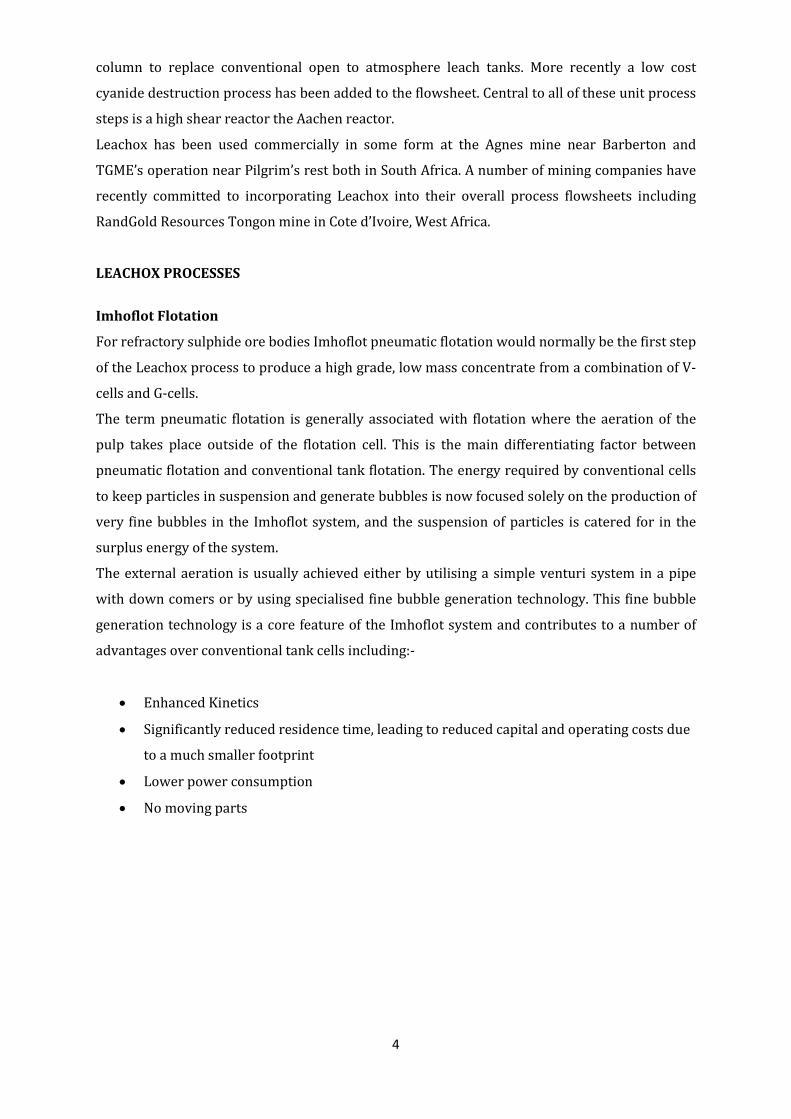
Imhoflot Flotation
For refractory sulphide ore bodies Imhoflot pneumatic flotation would normally be the first step
of the Leachox process to produce a high grade, low mass concentrate from a combination of V-
cells and G-cells.
The term pneumatic flotation is generally associated with flotation where the aeration of the
pulp takes place outside of the flotation cell. This is the main differentiating factor between
pneumatic flotation and conventional tank flotation. The energy required by conventional cells
to keep particles in suspension and generate bubbles is now focused solely on the production of
very fine bubbles in the Imhoflot system, and the suspension of particles is catered for in the
surplus energy of the system.
The external aeration is usually achieved either by utilising a simple venturi system in a pipe
with down comers or by using specialised fine bubble generation technology. This fine bubble
generation technology is a core feature of the Imhoflot system and contributes to a number of
advantages over conventional tank cells including:-
• Enhanced Kinetics
• Significantly reduced residence time, leading to reduced capital and operating costs due
to a much smaller footprint
• Lower power consumption
• No moving parts
5
Figure 1.0 Imhoflot G-cell –Cleaning a gold pyrite/arsenopyrite ore
Ultra Fine Grinding
Often when gold is locked in sulphides and silicates it is necessary to reduce the particle size to
a size where gold is liberated or partially liberated. For refractory ores this generally translates
into grinding below 10 microns and often to as low as 3-4 microns. Historically this was cost
prohibitive as the only mills that were available to do this were tumbling mills which become
highly inefficient at these low sizes particularly below 20 microns. The last 10-15 years
however, have seen the development of a number of grinding mills specifically designed for
ultra-fine grinding in the minerals industry. This has lead to a commensurate reduction in cost
to grind fine and has been the catalyst for the development of many refractory ore treatment
processes.
One of the drawbacks of grinding finer is that in addition to liberating the desired mineral it also
increases the surface area of other host minerals .This can result in order of magnitude
increases in reagent consumption particularly cyanide for the subsequent leaching process
unless cognisance of this is taken in the final process design.
In addition to the commercialisation of ultra fine grinding mills similar advances have taken
place in terms of developing specific ceramic grinding media for theses mills. This is beneficial
due to less iron contamination which would otherwise further consume lixiviants.
Ultra fine grinding mills can be basically split into three main types:-
• Vertical stirred ball mill- (high speed and low speed)
• High intensity horizontal disc mill
• High intensity vertical mill
6
Aachen Reactors and MMS Leach Column
In theory grinding ores to gold particle liberation size should then render them amenable to
cyanidation and thus no longer refractory. However for most ore bodies grinding to below 20
microns and particularly below 10 microns as previously mentioned grinding , whilst liberating
more gold, also liberates many other mineral species which effect the oxidative and cyanide
downstream process. This can dramatically increase reagent consumptions in open tank
oxidative leach processes often by an order of magnitude and thus the costs effectively
rendering lower grade ores uneconomic.
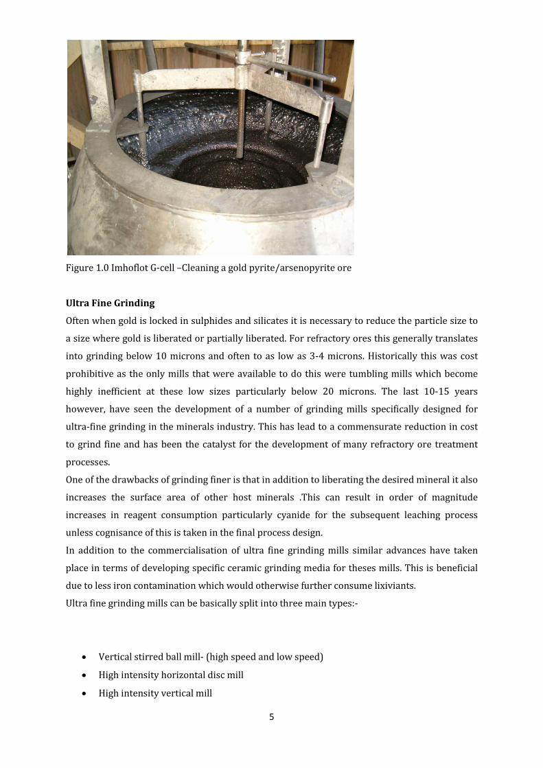
Fortunately this fatal flaw of many refractory processes is solved in the leachox process through
the use of Aachen reactors. The Aachen reactors are basically designed to facilitate mass
transfer by increasing the dispersion of oxygen gas into slurry. This is done by accelerating the
slurry stream at the gas addition point by the use of a ceramic inserts which increase shear
rates in the subsequent flow mixing zone. The resultant output is the generation of extremely
fine gas bubbles which then provide for a high rate of oxidation of sulphides.
Figure 2.0 Aachen Reactor –Principle of Operation
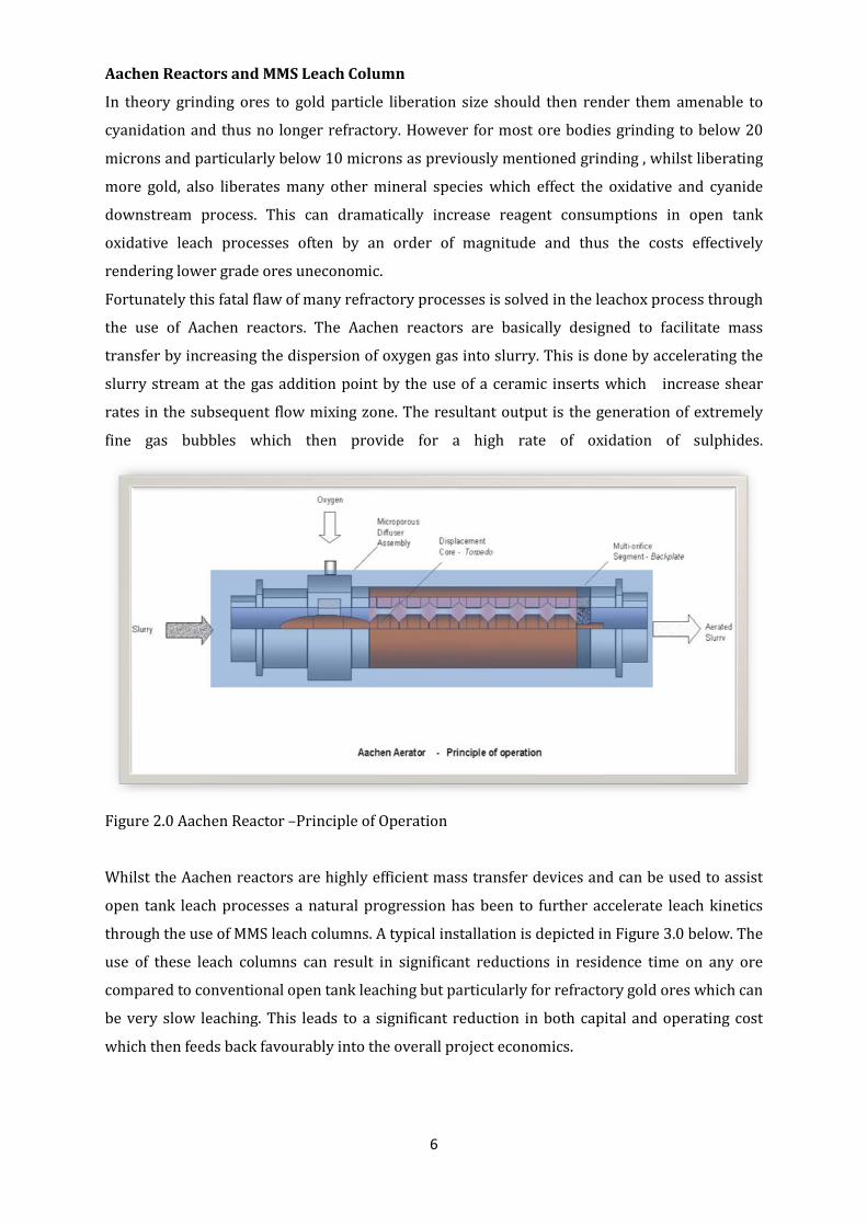
Whilst the Aachen reactors are highly efficient mass transfer devices and can be used to assist
open tank leach processes a natural progression has been to further accelerate leach kinetics
through the use of MMS leach columns. A typical installation is depicted in Figure 3.0 below. The
use of these leach columns can result in significant reductions in residence time on any ore
compared to conventional open tank leaching but particularly for refractory gold ores which can
be very slow leaching. This leads to a significant reduction in both capital and operating cost
which then feeds back favourably into the overall project economics.
7
Figure 3.0 Leach columns and Aachen reactors
Cyanide Destruction CN-D Process
With the introduction of the International Cyanide Code in the mining industry mining
companies are now forced to make provision for a cyanide destruction plant within their
financial model. Whilst the cost of this is obviously a concern for even a free leaching relatively
low cyanide consumption oxide ore it is of particular concern for many refractory processes due
to the much higher cyanide additions required. Whilst careful control of cyanide addition linked
to feed forward and feedback control systems can help to moderate residual cyanide tenors for
many operations this is insufficient and a further reduction in tenor is required. There are
several commercial processes available to do this and they can be broadly split into two
different categories namely destruction or recovery based processes. It is beyond the scope of
this paper to go into the relative merits and demerits of the individual processes but
unfortunately they all have inherent disadvantages mainly associated with high reagent
additions or high capex costs which can have a significantly adverse effect upon project
financials.
In order to address these concerns MMS has recently developed a low cost cyanide destruction
process, the CN-D Process. This process also incorporates the use of Aachen Reactors in another
mass transfer application. It has the ability to destroy cyanide to well below the levels required
8
by the Code at a fraction of the cost of existing processes. In the CN-D Process free and WAD
cyanide are oxidised by the Aachen Reactors using oxygen and activated carbon at specific Eh
and pH values in the presence of ore specific catalysts. The optional use of a catalyst can further
reduce SAD and total cyanide as well as cyanates if required. Apart from its inherent simplicity
the process, with its utilisation of activated carbon, has the added advantage of acting as a
"policeman" or safety net to further reduce any residual soluble loss of gold. MMS has calculated
the operating cost for this cyanide destruction process to be very competitive at approximately
US$ 0.20/ton treated based on a 450tph operation. This cost includes the license cost and
equipment supply cost but excludes the revenue from any incremental gold recovered which,
depending upon the upfront adsorption efficiency, has the potential to not only reduce this cost
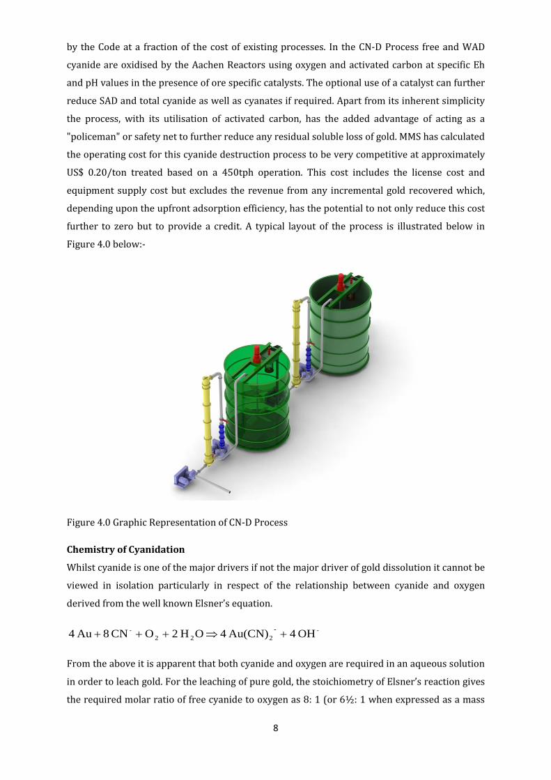
further to zero but to provide a credit. A typical layout of the process is illustrated below in
Figure 4.0 below:-
Figure 4.0 Graphic Representation of CN-D Process
Chemistry of Cyanidation
Whilst cyanide is one of the major drivers if not the major driver of gold dissolution it cannot be
viewed in isolation particularly in respect of the relationship between cyanide and oxygen
derived from the well known Elsner’s equation.
--222
- OH 4 Au(CN) 4 OH 2 O CN 8 Au 4 +⇒+++
From the above it is apparent that both cyanide and oxygen are required in an aqueous solution
in order to leach gold. For the leaching of pure gold, the stoichiometry of Elsner’s reaction gives
the required molar ratio of free cyanide to oxygen as 8: 1 (or 6½: 1 when expressed as a mass
9
ratio). As cyanide is the more expensive reagent, it is desirable from a financial point of view to
ensure that cyanide is the rate-limiting reagent. It is important to note that the rate of
dissolution of gold in alkaline cyanide solutions is controlled by the rate of dissolution of oxygen
from the bulk solution to the metal surface. This explains why the Aachen reactors are so
successful in boosting leach kinetics and reducing reagent consumption as the reactors are
specifically designed to maximise the phase interface surface area.
Pilot Plant Test work
MMS has a number of pilot plant facilities based in the United Kingdom, South Africa, Russia and
Australia for pilot scale testing of refractory flotation concentrates. These facilities include a
selection of both horizontal and vertical high intensity mills.
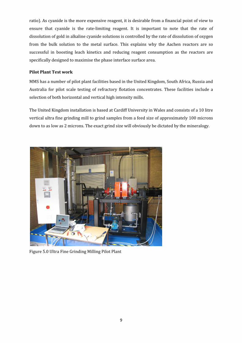
The United Kingdom installation is based at Cardiff University in Wales and consists of a 10 litre
vertical ultra fine grinding mill to grind samples from a feed size of approximately 100 microns
down to as low as 2 microns. The exact grind size will obviously be dictated by the mineralogy.
Figure 5.0 Ultra Fine Grinding Milling Pilot Plant
10
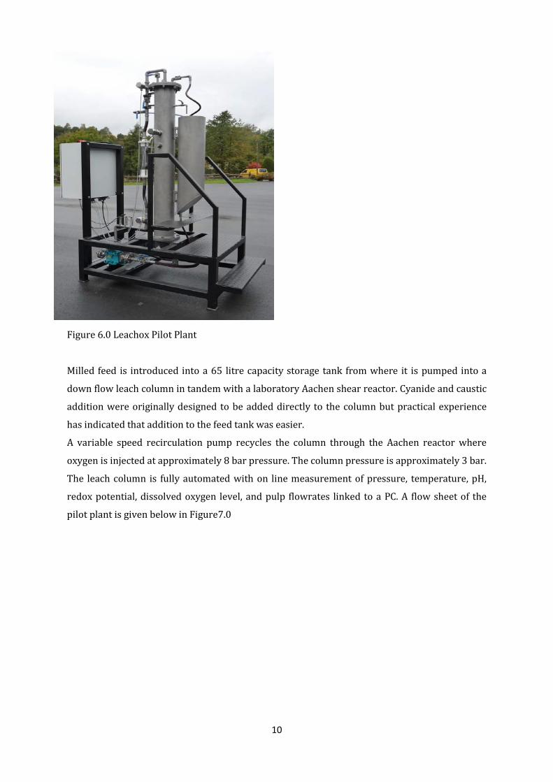
Figure 6.0 Leachox Pilot Plant
Milled feed is introduced into a 65 litre capacity storage tank from where it is pumped into a
down flow leach column in tandem with a laboratory Aachen shear reactor. Cyanide and caustic
addition were originally designed to be added directly to the column but practical experience
has indicated that addition to the feed tank was easier.
A variable speed recirculation pump recycles the column through the Aachen reactor where
oxygen is injected at approximately 8 bar pressure. The column pressure is approximately 3 bar.
The leach column is fully automated with on line measurement of pressure, temperature, pH,
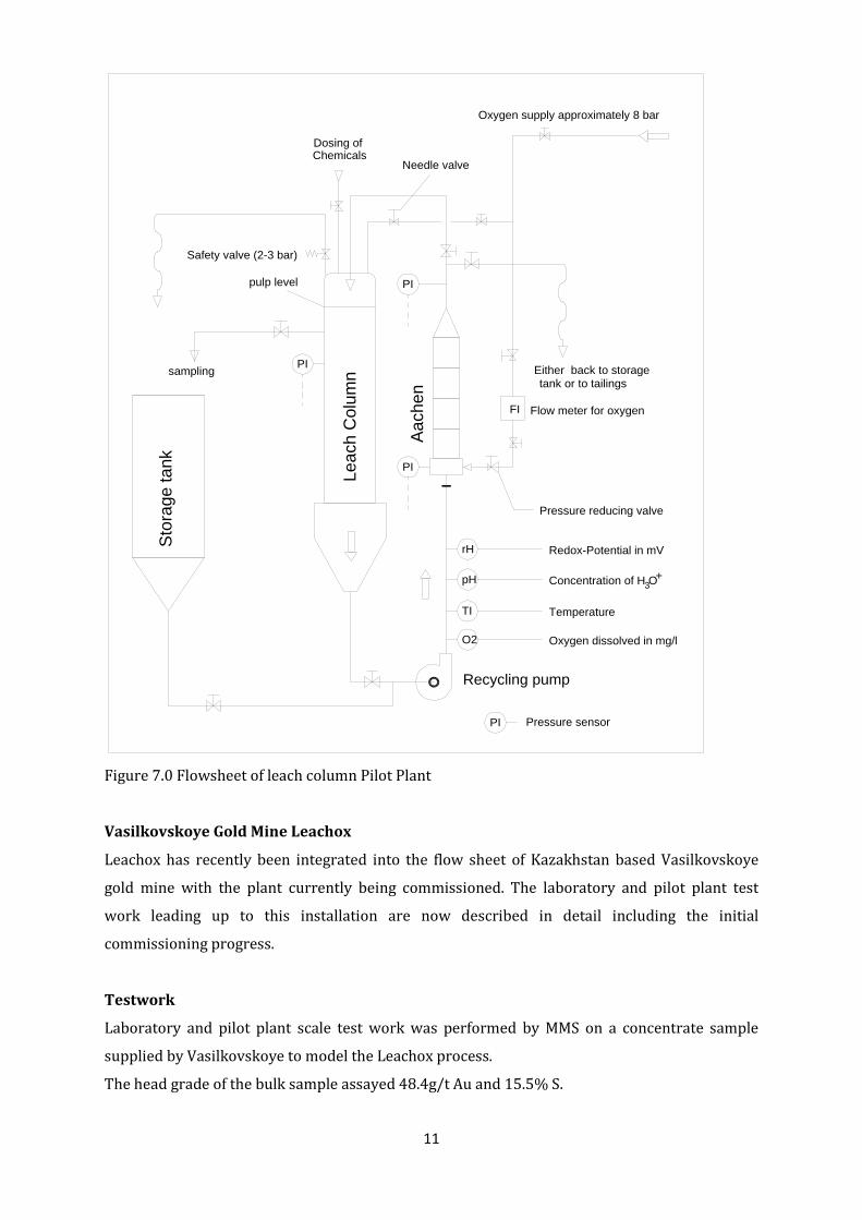
redox potential, dissolved oxygen level, and pulp flowrates linked to a PC. A flow sheet of the
pilot plant is given below in Figure7.0
11
Figure 7.0 Flowsheet of leach column Pilot Plant
Vasilkovskoye Gold Mine Leachox
Leachox has recently been integrated into the flow sheet of Kazakhstan based Vasilkovskoye
gold mine with the plant currently being commissioned. The laboratory and pilot plant test
work leading up to this installation are now described in detail including the initial
commissioning progress.
Testwork
Laboratory and pilot plant scale test work was performed by MMS on a concentrate sample
supplied by Vasilkovskoye to model the Leachox process.
The head grade of the bulk sample assayed 48.4g/t Au and 15.5% S.
PI
rH
Oxygen supply approximately 8 bar
Safety valve (2-3 bar)
Either back to storagetank or to tailings
Pressure reducing valve
Needle valve
PI
FI
pH
TI
O2
sampling
Dosing of Chemicals
PIpulp level
Leac
h C
olum
n
Stor
age
tank
Redox-Potential in mV
Concentration of H O
Temperature
Oxygen dissolved in mg/l
3+
Flow meter for oxygenAa
chen
PI Pressure sensor
Recycling pump
12
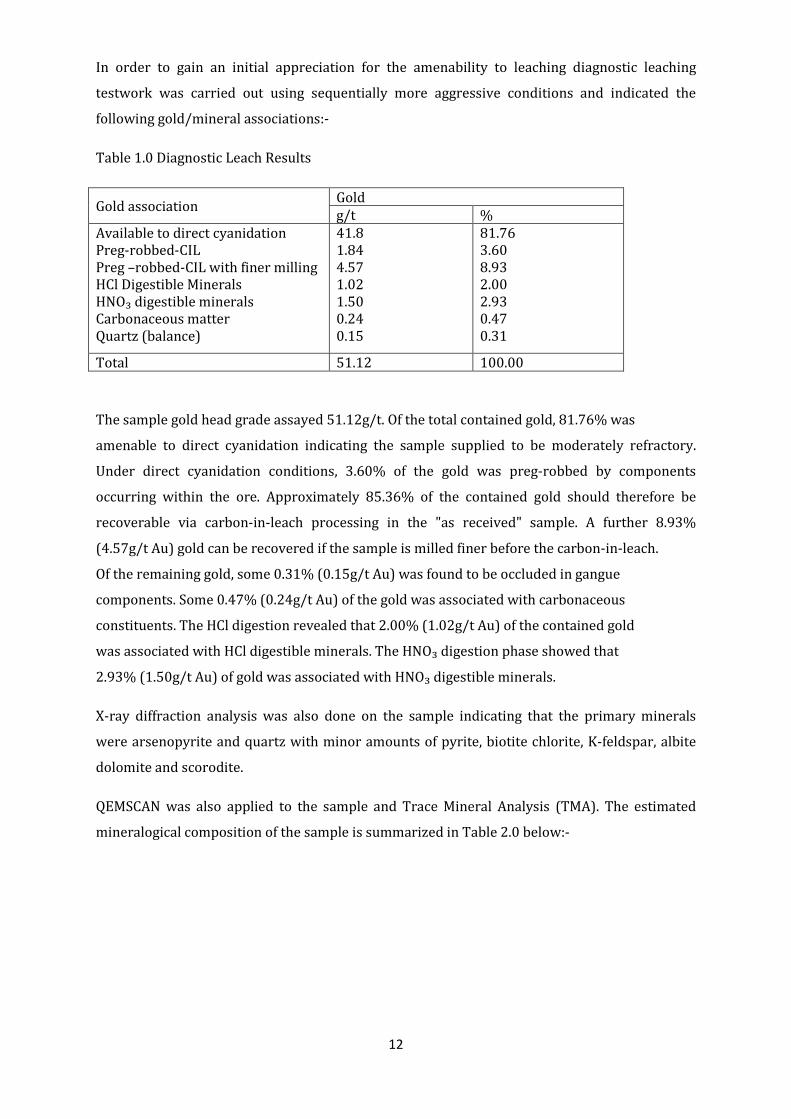
In order to gain an initial appreciation for the amenability to leaching diagnostic leaching
testwork was carried out using sequentially more aggressive conditions and indicated the
following gold/mineral associations:-
Table 1.0 Diagnostic Leach Results
Gold association Gold g/t %
Available to direct cyanidation Preg-robbed-CIL Preg –robbed-CIL with finer milling HCl Digestible Minerals HNO₃ digestible minerals Carbonaceous matter Quartz (balance)
41.8 1.84 4.57 1.02 1.50 0.24 0.15
81.76 3.60 8.93 2.00 2.93 0.47 0.31
Total 51.12 100.00
The sample gold head grade assayed 51.12g/t. Of the total contained gold, 81.76% was
amenable to direct cyanidation indicating the sample supplied to be moderately refractory.
Under direct cyanidation conditions, 3.60% of the gold was preg-robbed by components
occurring within the ore. Approximately 85.36% of the contained gold should therefore be
recoverable via carbon-in-leach processing in the "as received" sample. A further 8.93%
(4.57g/t Au) gold can be recovered if the sample is milled finer before the carbon-in-leach.
Of the remaining gold, some 0.31% (0.15g/t Au) was found to be occluded in gangue
components. Some 0.47% (0.24g/t Au) of the gold was associated with carbonaceous
constituents. The HCl digestion revealed that 2.00% (1.02g/t Au) of the contained gold
was associated with HCl digestible minerals. The HNO₃ digestion phase showed that
2.93% (1.50g/t Au) of gold was associated with HNO₃ digestible minerals.
X-ray diffraction analysis was also done on the sample indicating that the primary minerals
were arsenopyrite and quartz with minor amounts of pyrite, biotite chlorite, K-feldspar, albite
dolomite and scorodite.
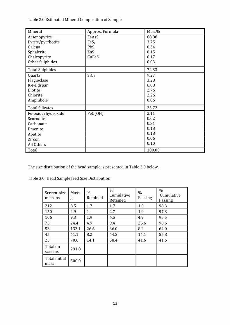
QEMSCAN was also applied to the sample and Trace Mineral Analysis (TMA). The estimated
mineralogical composition of the sample is summarized in Table 2.0 below:-
13
Table 2.0 Estimated Mineral Composition of Sample
Mineral Approx. Formula Mass% Arsenopyrite Pyrite/pyrrhotite Galena Sphalerite Chalcopyrite Other Sulphides
FeAsS FeS₂ PbS ZnS CuFeS
68.88 3.75 0.34 0.15 0.17 0.03
Total Sulphides 72.33 Quartz Plagioclase K-Feldspar Biotite Chlorite Amphibole
SiO₂ 9.27 3.28 6.08 2.76 2.26 0.06
Total Silicates 23.72 Fe-oxide/hydroxide FeO(OH)
2.11 0.02 0.31 0.18 0.18 0.06 0.10
Scorodite Carbonate Ilmenite Apatite Zircon All Others Total 100.00
The size distribution of the head sample is presented in Table 3.0 below.
Table 3.0: Head Sample feed Size Distribution
Screen size microns
Mass g
% Retained
% Cumulative Retained
% Passing
% Cumulative Passing
212 8.5 1.7 1.7 1.0 98.3 150 4.9 1 2.7 1.9 97.3 106 9.3 1.9 4.5 4.9 95.5 75 24.4 4.9 9.4 26.6 90.6 53 133.1 26.6 36.0 8.2 64.0 45 41.1 8.2 44.2 14.1 55.8 25 70.6 14.1 58.4 41.6 41.6 Total on screens 291.8
Total initial mass 500.0
14
The screen analysis indicated that the “as received” sample had a grind of 90.6% passing 75
microns. 55.8% of the material passed through 45 microns whilst 41.6% passed through 25
microns.
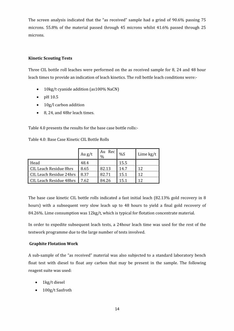
Kinetic Scouting Tests
Three CIL bottle roll leaches were performed on the as received sample for 8, 24 and 48 hour
leach times to provide an indication of leach kinetics. The roll bottle leach conditions were:-
• 10kg/t cyanide addition (as100% NaCN)
• pH 10.5
• 10g/l carbon addition
• 8, 24, and 48hr leach times.
Table 4.0 presents the results for the base case bottle rolls:-
Table 4.0: Base Case Kinetic CIL Bottle Rolls
Au g/t Au Rec % %S Lime kg/t
Head 48.4 15.5 CIL Leach Residue 8hrs 8.65 82.13 14.7 12 CIL Leach Residue 24hrs 8.37 82.71 15.1 12 CIL Leach Residue 48hrs 7.62 84.26 15.1 12
The base case kinetic CIL bottle rolls indicated a fast initial leach (82.13% gold recovery in 8
hours) with a subsequent very slow leach up to 48 hours to yield a final gold recovery of
84.26%. Lime consumption was 12kg/t, which is typical for flotation concentrate material.
In order to expedite subsequent leach tests, a 24hour leach time was used for the rest of the
testwork programme due to the large number of tests involved.
Graphite Flotation Work
A sub-sample of the “as received” material was also subjected to a standard laboratory bench
float test with diesel to float any carbon that may be present in the sample. The following
reagent suite was used:
• 1kg/t diesel
• 100g/t Sasfroth
15
No mass was pulled off in the graphite float test indicating that if there was any graphite present
it occurred in a very low concentration.
Leachox Modelling Work
In order to assess the applicability of the Leachox process more detailed simulation work was
conducted which involved the following:-
Separate aliquots of sample were milled to target d90’s of 45, 25, 15, 10 and 5 microns
respectively.
• At each grind, samples were split into two representative portions and subjected to:
o 24 hour bottle roll leaches with and without carbon
o Aachen simulation followed by 24hour bottle roll leaches with and without
carbon
• In addition, the sample at a target grind of 5microns was further subjected to:
o A 48 hour leach where carbon was added after 24hours to assess whether
any possible preg-robbed gold could be retrieved by contacting with carbon.
o A 24hour conditioning with diesel followed by a CIL bottle roll leach.
The conditions for the bottle roll leach tests were:-
• 20kg/t cyanide addition
• pH 10.5
• 10g/l carbon addition on bottle rolls with carbon
• 10kg/t diesel on bottle rolls with diesel
• Leach times as per above.
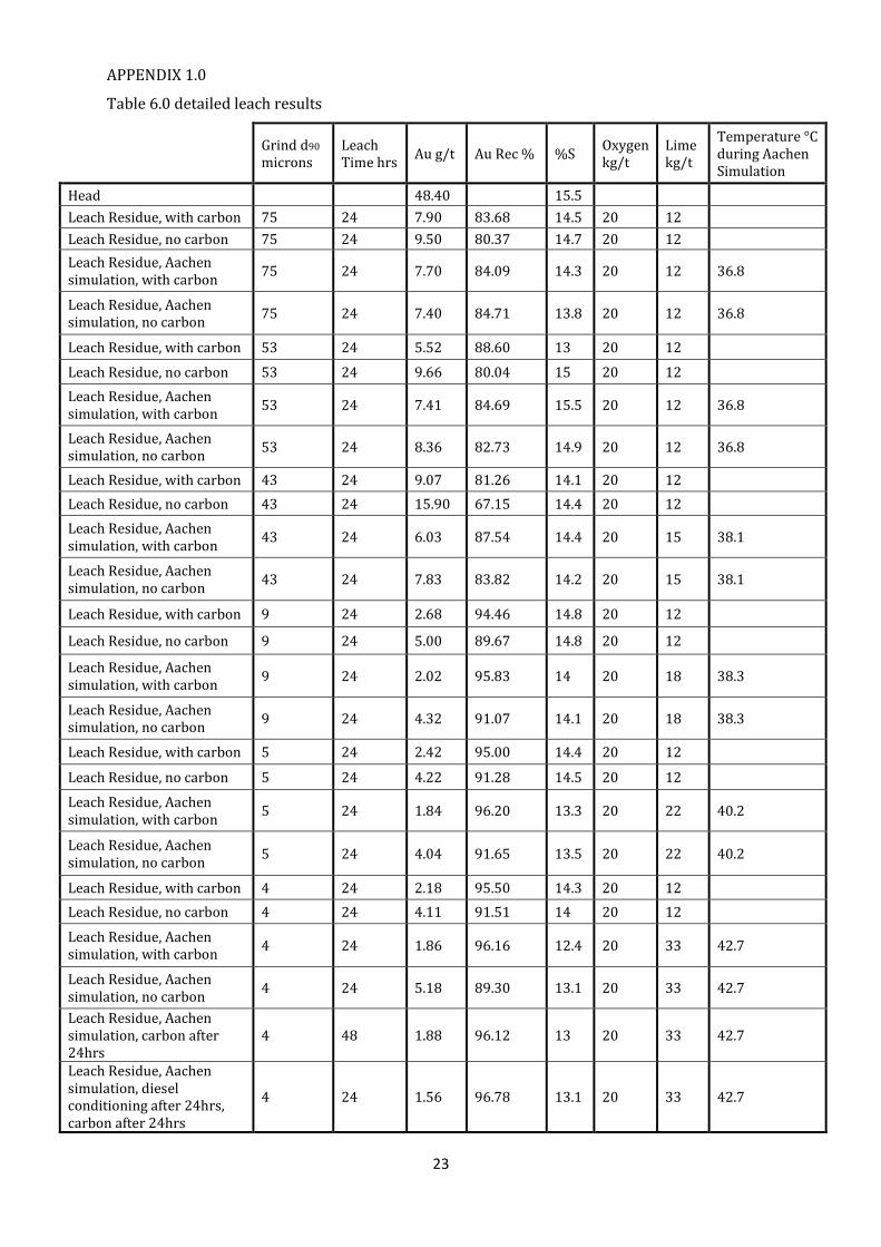
Testwork results are summarised in Table 5.0 below with detailed results provided in Appendix
1.0.
16
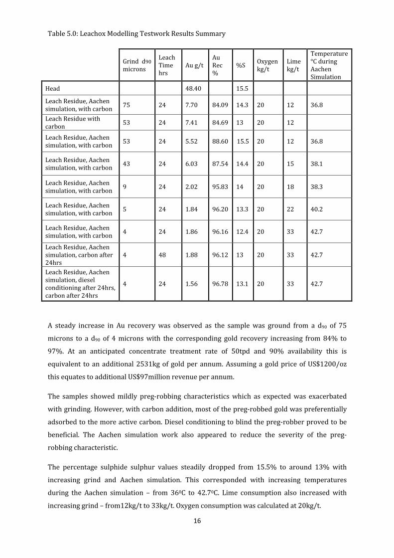
Table 5.0: Leachox Modelling Testwork Results Summary
Grind d90 microns
Leach Time hrs
Au g/t Au Rec %
%S Oxygen kg/t
Lime kg/t
Temperature °C during Aachen Simulation
Head 48.40 15.5
Leach Residue, Aachen simulation, with carbon 75 24 7.70 84.09 14.3 20 12 36.8
Leach Residue with carbon 53 24 7.41 84.69 13 20 12 Leach Residue, Aachen simulation, with carbon 53 24 5.52 88.60 15.5 20 12 36.8
Leach Residue, Aachen simulation, with carbon 43 24 6.03 87.54 14.4 20 15 38.1
Leach Residue, Aachen simulation, with carbon 9 24 2.02 95.83 14 20 18 38.3
Leach Residue, Aachen simulation, with carbon 5 24 1.84 96.20 13.3 20 22 40.2
Leach Residue, Aachen simulation, with carbon 4 24 1.86 96.16 12.4 20 33 42.7
Leach Residue, Aachen simulation, carbon after 24hrs
4 48 1.88 96.12 13 20 33 42.7
Leach Residue, Aachen simulation, diesel conditioning after 24hrs, carbon after 24hrs
4 24 1.56 96.78 13.1 20 33 42.7
A steady increase in Au recovery was observed as the sample was ground from a d90 of 75
microns to a d90 of 4 microns with the corresponding gold recovery increasing from 84% to
97%. At an anticipated concentrate treatment rate of 50tpd and 90% availability this is
equivalent to an additional 2531kg of gold per annum. Assuming a gold price of US$1200/oz
this equates to additional US$97million revenue per annum.
The samples showed mildly preg-robbing characteristics which as expected was exacerbated
with grinding. However, with carbon addition, most of the preg-robbed gold was preferentially
adsorbed to the more active carbon. Diesel conditioning to blind the preg-robber proved to be
beneficial. The Aachen simulation work also appeared to reduce the severity of the preg-
robbing characteristic.
The percentage sulphide sulphur values steadily dropped from 15.5% to around 13% with
increasing grind and Aachen simulation. This corresponded with increasing temperatures
during the Aachen simulation – from 360C to 42.70C. Lime consumption also increased with
increasing grind – from12kg/t to 33kg/t. Oxygen consumption was calculated at 20kg/t.
17
Process description
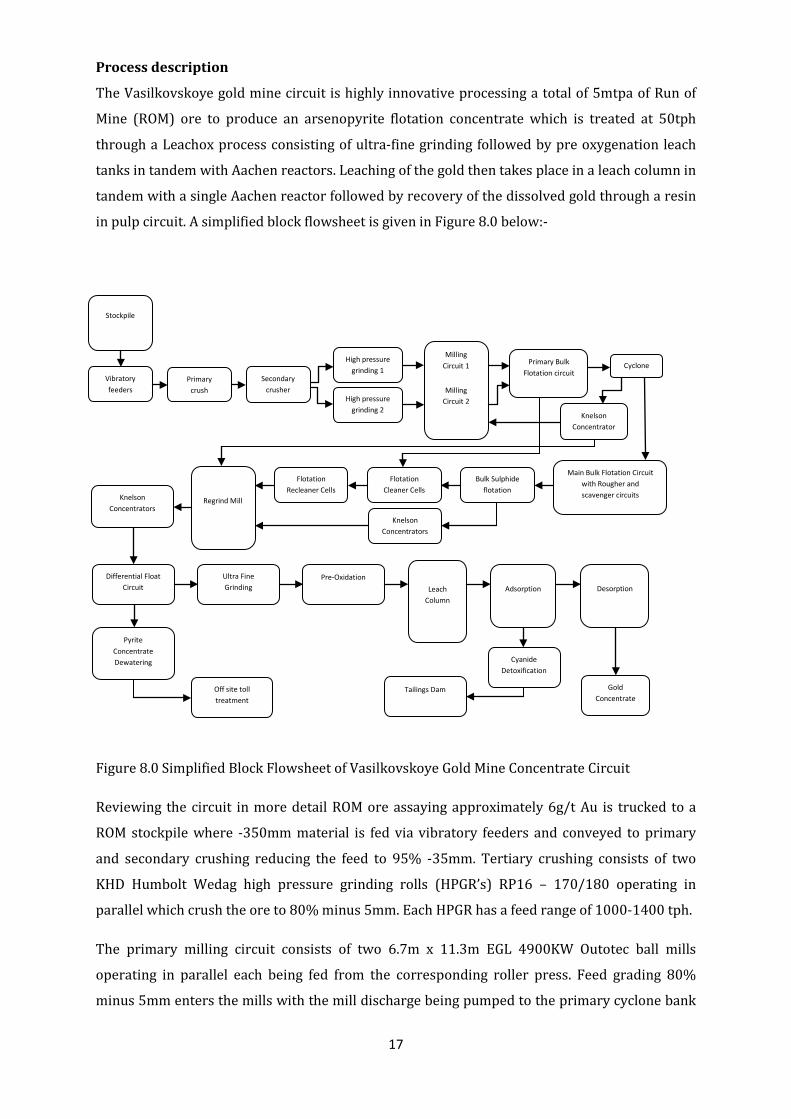
The Vasilkovskoye gold mine circuit is highly innovative processing a total of 5mtpa of Run of
Mine (ROM) ore to produce an arsenopyrite flotation concentrate which is treated at 50tph
through a Leachox process consisting of ultra-fine grinding followed by pre oxygenation leach
tanks in tandem with Aachen reactors. Leaching of the gold then takes place in a leach column in
tandem with a single Aachen reactor followed by recovery of the dissolved gold through a resin
in pulp circuit. A simplified block flowsheet is given in Figure 8.0 below:-
Figure 8.0 Simplified Block Flowsheet of Vasilkovskoye Gold Mine Concentrate Circuit
Reviewing the circuit in more detail ROM ore assaying approximately 6g/t Au is trucked to a
ROM stockpile where -350mm material is fed via vibratory feeders and conveyed to primary
and secondary crushing reducing the feed to 95% -35mm. Tertiary crushing consists of two
KHD Humbolt Wedag high pressure grinding rolls (HPGR’s) RP16 – 170/180 operating in
parallel which crush the ore to 80% minus 5mm. Each HPGR has a feed range of 1000-1400 tph.
The primary milling circuit consists of two 6.7m x 11.3m EGL 4900KW Outotec ball mills
operating in parallel each being fed from the corresponding roller press. Feed grading 80%
minus 5mm enters the mills with the mill discharge being pumped to the primary cyclone bank
Stockpile
Primary crush
Secondary crusher
Vibratory feeders
High pressure grinding 2
High pressure grinding 1
Milling Circuit 1
Milling Circuit 2
Primary Bulk Flotation circuit
Main Bulk Flotation Circuit with Rougher and scavenger circuits
Knelson Concentrator
Bulk Sulphide flotation
Flotation Cleaner Cells
Cyclone
Regrind Mill
Flotation Recleaner Cells
Knelson Concentrators
Knelson Concentrators
Differential Float Circuit
Ultra Fine Grinding
Pyrite Concentrate Dewatering
Pre-Oxidation
Leach Column
Desorption Adsorption
Cyanide Detoxification
Gold Concentrate
Tailings Dam Off site toll treatment
18
(6 cyclones). The 60% minus 74 micron cyclone product is then pumped to the primary bulk
flotation cells, with the underflow being returned back to the mills. Primary bulk flotation tails
are again cycloned (16 cyclones per unit) with the corresponding overflow of 90% minus 74
microns pumped to the main bulk flotation cells .The underflow is first screened at 1.5 mm
(oversize returned to mill) then treated in a Knelson KCXD 70 separator, the concentrate being
pumped to the regrind mill, with the tailings returned to the mill.
Following the primary float a bulk sulphide flotation circuit is then installed. This consists of 2
banks of Outotec 130m³ tank cells, the first three cells of each bank are fed with d60 minus 74
micron primary cyclone (6 cyclones per side) overflow. The concentrate is sent for cleaning,
whilst the tails are fed to the secondary cyclones (16 cyclones per side) set at a d90 of 74
microns. The secondary cyclone underflow is screened at 1.5mm and fed to a Knelson Kcxd 70
separator, the tailings of which report back to the ball mills ,the concentrate being returned for
regrind. The remainder of the bulk circuit is split into secondary roughers and scavengers. The
scavenger concentrate is recycled to secondary rougher feed, the secondary cons reporting for
cleaning and recleaning. The cleaner circuit is 2 parallel banks of 4 x 10m3 Outotec Tank cells.
The recleaner circuit consists of 2 parallel banks of 3 x 5m3 Outotec Tank cells. Cleaner tails
report to primary roughing whilst recleaner tails are recycled to cleaner feed with recleaner
concentrate being sent for regrind.
Flotation tails are first screened at 1.5 mm then fed to primary ( Kcvd 64 ) then cleaner (Kcvd
32 ) Knelson separators, both tails reporting to final tails the concentrate being sent for regrind.
The bulk sulphide concentrate is fed to a 7mx4m regrind mill with a 25mm ball charge .The mill
product is then subjected to primary then secondary cyclone banks the latter resulting in a
product of 95% minus 45 microns, the underflows of both banks being returned to the regrind
mill. The secondary cyclone bank product is then screened at 1.0mm before being sent to
primary then cleaner knelson separators, the cleaner concentrate joining the final pyrite
concentrate ,whilst both tailings combining together to form the pyrite/arsenopyrite
differential flotation plant feed.
The differential arsenopyrite/pyrite float circuit consists of 3 stage conditioning followed by 9 x
5m3 Outotec tank Cells as the primary float cells, followed by a further 3 x 5m3 Outotec Tank
Cells as cleaners and 2x 2 Outotec TC 1.5 – 2.0 standard cells as recleaners. The recleaned pyrite
concentrate is then thickened in an Outotec 4m thickener, filtered in a Metso pressure filter and
then despatched for roasting and subsequent final gold recovery at an external smelter. The
cleaner and recleaner tailings rejoin the primary segregation tailings as the arsenopyrite
concentrate.
19
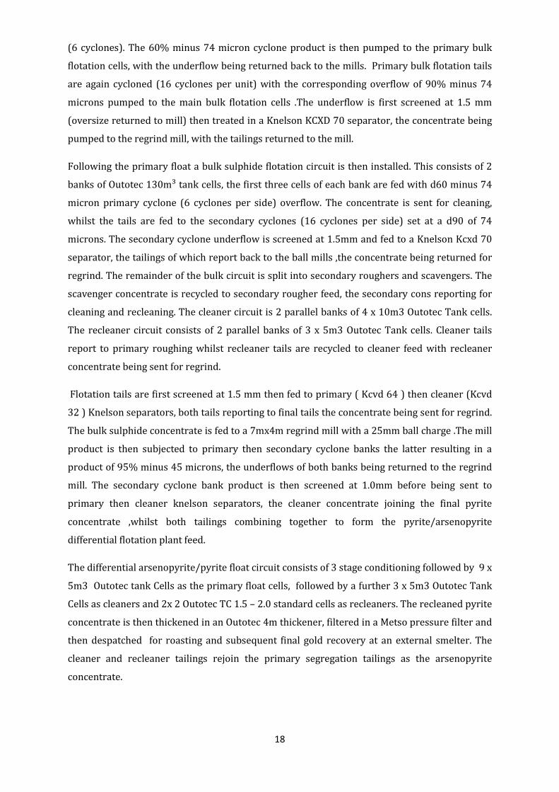
The arsenopyrite concentrate grading approximately 50g/t Au and 16% sulphur is then
thickened to approximately 55% solids by weight and fed to the first stage of the Leachox
process consisting of three 2000 litre vertical stirred fine grinding mills to produce a product at
90% minus 4 microns from the 90% -45 microns feed. Pre-oxygentation then takes place in 4x
650m³ pre-oxygenation tanks .Each tank is run in tandem with two REA-Au 400 Aachen
reactors). The slurry is then leached in a leach column (again in circulation with one Aachen
reactor).Lime and cyanide are added to the leach feed at additions of 30kg/t and 1kg/t
respectively. Oxygen is added to the Aachen reactors with an overall consumption of
approximately 20kg/t .Diesel is also added to the leach feed to combat preg robbing .The
subsequent downstream circuit for recovering the dissolved gold consists of a carbon
adsorption and associated elution circuit. Final tails are subjected to a cyanide detoxification
stage before pumping to the tailings facility. The Leachox section of the overall flowsheet is
given in Figure 9.0 below and a detailed process flowsheet is given in Appendix 2.0.
Figure 9.0 MMS Leachox Circuit at Vasilkovskoye
20
COMMISSIONING EXPERIENCE
The MMS Leachox plant was installed in August 2009. Whilst the plant is in partial operation
commissioning has not been signed off at present due to:-
• Failure of and delays in commissioning upstream processes (in pit conveyors, ball mills,
flotation circuit)
• Delay in the supply of essential control equipment outside of the Leachox contract scope
i.e. density and flow control for UFG feed, non return valves, pressure gauges,
flowmeters and regulators for the Aachen aerators
• Adverse weather conditions (coldest winter for several decades)
• Labour being drawn from the local community unfamiliar with operating process plants
resulting in a long learning curve.
Initially the commissioning centred on preparing the hydraulic motors, power packs, and
electronic control systems for the ultra fine grinding mills, the Aachen reactors having already
been installed by the main engineering contractor TOMS. This progressed smoothly with the net
result that by October 2009 all 3 mills had been water commissioned with a nominal bead load.
Slurry feed commissioning commenced in November 2009 with a modified upstream circuit
limited to only the primary roller press, ball mill combination running. This only provided
sufficient feed to run one of the two banks of bulk sulphide rougher flotation cells, together with
it’s corresponding cleaner, and recleaner banks. The differential flotation circuit was not yet
operational at this stage so the bulk sulphide concentrate was reground to a d95 of 45 microns,
thickened then pumped directly to the fine grinding mills.
Initially the fine grinding mills were operated at approximately 110 rpm or 50% of their rated
maximum together with a reduced bead load as modifications involving changing and
reconfiguring the bearings in the bearing housings were deemed necessary by the supplier, with
this work finally completed in December 2009. During March 2010 the fine grinding mill PLC’s
were connected up to the mine’s Profibus system allowing full SCADA control of the mill.
The upstream secondary milling circuit only became operational during March 2010 as did the
differential flotation circuit; however ongoing problems with the upstream ball mill gearboxes
meant that the plants rated throughput of 1050 tons per hour was only recently achieved. These
upstream problems have often resulted in a non steady state feed conditions to the Leachox
circuit with large fluctuations being seen in both tonnage and density.
21
This situation has been further exacerbated by delays in essential control equipment such as
flowmeters and density meters. Consequently to date the mills have not been run at their
combined rated tonnage of approximately 50tph and therefore not yet fully tested however
accepting this the designated grind of 90% minus 4 microns has easily been achieved even at
these fluctuating tonnages.
In terms of the Aachen reactors commissioning the same problems were experienced with the
non steady state feed conditions. Choking of the Aachens has occurred as expected as they were
run without essential control equipment such as slurry non return valves, pressure regulators,
flowmeters etc. The delivery of this equipment was outside of MMS’s scope of supply and is
currently still being installed with experience from other installations indicating that once
installed as per specification this will resolve the problem.
As alluded to earlier there has also been a definite and steep learning curve due to the
inexperienced plant personnel with the commissioning focus understandably being on
upstream equipment and only more recently moving downstream to the Leachox process.
Metallurgical leach test results are still awaited from Vasilkovskoye to provide base line
recovery data and indications of improving leach efficiency as greater availability and increased
steady state upstream operations are achieved. At present then it is premature to comment on
the recovery increase directly attributable to Leachox although experience to date indicates that
design recoveries should comfortably be achieved when the Leachox circuit is operated
correctly.
SUMMARY
Historically mining companies have steered clear of refractory gold projects where possible due
to a combination of perceived processing difficulties and poor economics associated with low
recoveries. The paper has however illustrated that recent advances in technology integrated
into the Leachox process have now eliminated these concerns with many companies now
actively investigating new refractory projects and re-assessing old projects which were
previously uneconomic.
The background to the Leachox process for treatment of refractory gold ores is detailed from
initial process selection, through equipment selection and testwork to a commercial application
resulting in a refractory gold concentrate treatment plant 50% larger than the current largest
bi-oxidation plant in the world. In summary then Leachox provides a low operating and capital
cost compared to other processes albeit at a marginally lower recovery resulting in improved
overall economics.
ACKNOWLEDGEMENTS
The authors would like to thank the management of Vasgold for their assistance and support.
22
REFERENCES
Botz, M.M., “Overview of Cyanide Treatment Methods”, Mining Environmental Management,
Mining Journal Ltd., London, UK, pp 28-30, 2001
“Leachox Modelling Testwork on Kazzinc Vasilkovskoye sample” internal communication,
Maelgwyn Minerals Services Africa, South Africa 17 September 2007
Coetzee, L .L, Martin, G.J,“SGS Mineralogical Report no Min 0707/127”South Africa 26
September 2007
O’Connel , S.P,”SGS Report no Met 07/281-Quantification Diagnostic Leach Appraisal on a
Maelgwyn Minerals Sample, 26th September 2007
Imhof, R.M., Battersby, M.J.G., Parra, F., Sanchez-Pino, S., (2005). The Successful Application of
Pneumatic Flotation Technology for the Removal of Silica by Reverse Flotation at the Iron Ore
Pellet Plant of Compania Minera Huasco, Chile. Centenary of Flotation Symposium, 5 – 9 June
2005, Brisbane, Australia.
Battersby, M.J.G., Fletcher, M.G., Imhof, R.M., Singh, A.A., Puder, F., (2005). The Advantages of the
Imhoflot G-Cell Pneumatic Flotation Process with Centrifugal Froth Removal – Two Case
Studies. Randol Innovative Metallurgy Forum, 21 – 24 August 2005, Perth, Australia.
Sanchez-Pino, S., Sanchez-Baquedano, A., Imhof, R.M., Battersby, M. J. G., (2006). Is Bigger
Always Better in Flotation? The Imhoflot G-Cell. PROCMIN 2006 IV International Mineral
Processing Seminar, 22-24 November 2006, Santiago, Chile.
Battersby, M.J.G., Imhof, R.M., Fletcher, M.G., Puder, F., (2007). The Efficient Recovery of Kaolin
from a Hydrocyclone Plant Middlings Steam Utilising Imhoflot G-Cell Pneumatic Flotation. SME
2007 Annual Meeting 26-28 February 2007, St Louis, USA
Imhof, R.M., Fletcher, M.G., Singh, A.A., Vathavooran, A., (2007). Application of Imhoflot G-Cell
Centrifugal Flotation Technology. SAIMM Conference, Flotation Cell Technology in the 21st
Century, 20 June 2007, Johannesburg, South Africa.
Sanchez-Pino, S., Sanchez-Baquedano, A., Imhof, R.M., (2008). Imhoflot G-Cell Pneumatic
Flotation Technology for Fine Particle Applications. PROCMIN 2008 V International Mineral
Processing Seminar, 22-24 October 2008, Santiago, Chile.
23
APPENDIX 1.0
Table 6.0 detailed leach results
Grind d90 microns
Leach Time hrs Au g/t Au Rec % %S Oxygen
kg/t Lime kg/t
Temperature °C during Aachen Simulation
Head 48.40 15.5 Leach Residue, with carbon 75 24 7.90 83.68 14.5 20 12 Leach Residue, no carbon 75 24 9.50 80.37 14.7 20 12 Leach Residue, Aachen simulation, with carbon 75 24 7.70 84.09 14.3 20 12 36.8
Leach Residue, Aachen simulation, no carbon 75 24 7.40 84.71 13.8 20 12 36.8
Leach Residue, with carbon 53 24 5.52 88.60 13 20 12
Leach Residue, no carbon 53 24 9.66 80.04 15 20 12 Leach Residue, Aachen simulation, with carbon 53 24 7.41 84.69 15.5 20 12 36.8
Leach Residue, Aachen simulation, no carbon 53 24 8.36 82.73 14.9 20 12 36.8
Leach Residue, with carbon 43 24 9.07 81.26 14.1 20 12 Leach Residue, no carbon 43 24 15.90 67.15 14.4 20 12 Leach Residue, Aachen simulation, with carbon 43 24 6.03 87.54 14.4 20 15 38.1
Leach Residue, Aachen simulation, no carbon 43 24 7.83 83.82 14.2 20 15 38.1
Leach Residue, with carbon 9 24 2.68 94.46 14.8 20 12
Leach Residue, no carbon 9 24 5.00 89.67 14.8 20 12 Leach Residue, Aachen simulation, with carbon 9 24 2.02 95.83 14 20 18 38.3
Leach Residue, Aachen simulation, no carbon 9 24 4.32 91.07 14.1 20 18 38.3
Leach Residue, with carbon 5 24 2.42 95.00 14.4 20 12
Leach Residue, no carbon 5 24 4.22 91.28 14.5 20 12
Leach Residue, Aachen simulation, with carbon 5 24 1.84 96.20 13.3 20 22 40.2
Leach Residue, Aachen simulation, no carbon 5 24 4.04 91.65 13.5 20 22 40.2
Leach Residue, with carbon 4 24 2.18 95.50 14.3 20 12 Leach Residue, no carbon 4 24 4.11 91.51 14 20 12
Leach Residue, Aachen simulation, with carbon 4 24 1.86 96.16 12.4 20 33 42.7
Leach Residue, Aachen simulation, no carbon 4 24 5.18 89.30 13.1 20 33 42.7
Leach Residue, Aachen simulation, carbon after 24hrs
4 48 1.88 96.12 13 20 33 42.7
Leach Residue, Aachen simulation, diesel conditioning after 24hrs, carbon after 24hrs
4 24 1.56 96.78 13.1 20 33 42.7
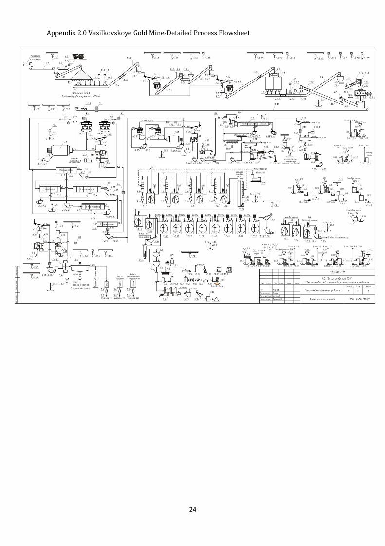
24
Appendix 2.0 Vasilkovskoye Gold Mine-Detailed Process Flowsheet