Embed Size (px)
Citation preview
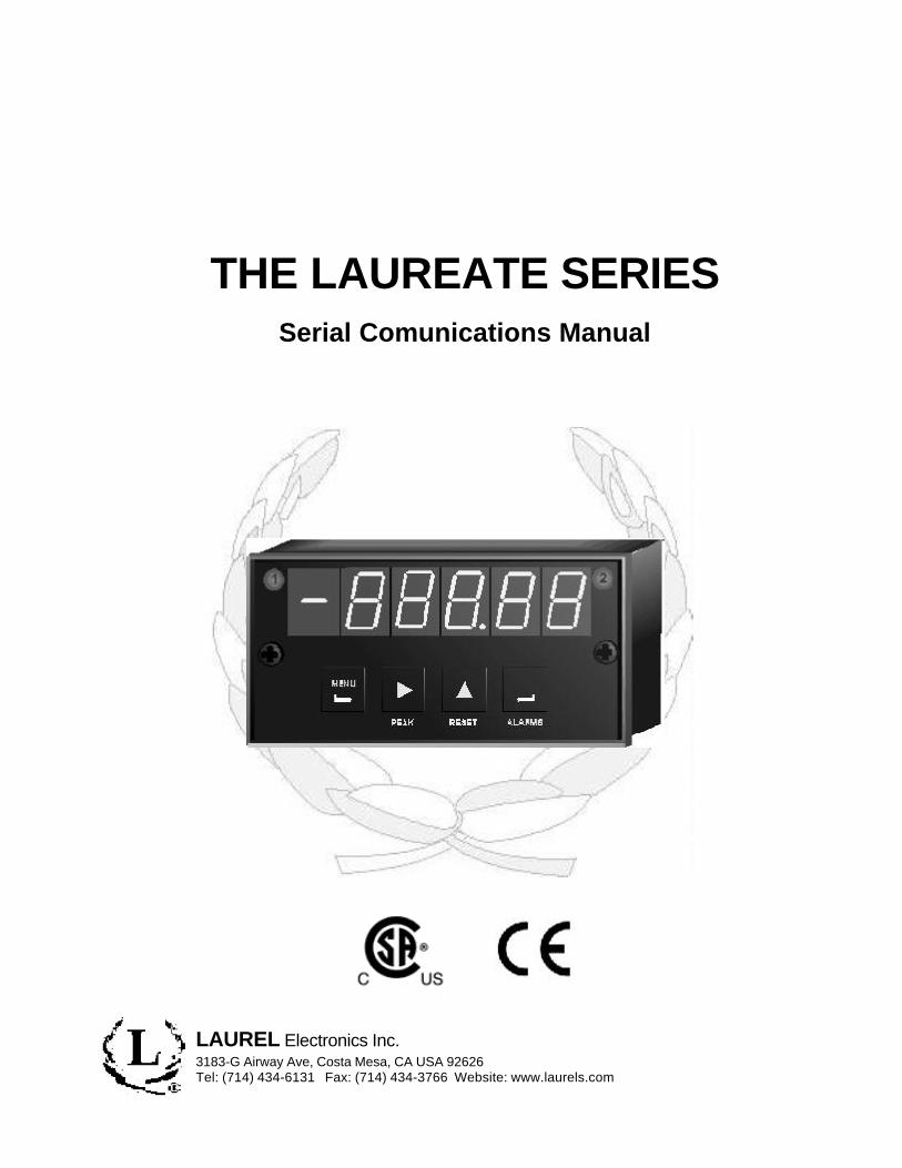
THE LAUREATE SERIESSerial Comunications Manual
LAUREL Electronics Inc.3183-G Airway Ave, Costa Mesa, CA USA 92626Tel: (714) 434-6131 Fax: (714) 434-3766 Website: www.laurels.com
CONTENTS
1.0 HARDWARE AND SOFTWARE SETUP ...........................................................................21.1 SELECTING THE MODULAR CABLE TYPE..........................................................21.2 RS-232 AND RS-485 WIRING CONNECTIONS .....................................................31.3 RS-232 AND RS-485 JUMPER SETTINGS ............................................................51.4 SERIAL INTERFACE SETUP - ALL METERS .......................................................61.5 SERIAL INTERFACE SETUP - COUNTER ONLY..................................................71.6 SERIAL INTERFACE SETUP - SCALE METER ONLY.........................................7
2.0 INTERFACE INFORMATION ...............................................................................................83.0 RS232 AND RS485 FORMAT............................................................................................8
3.1 SERIAL COMMUNICATION FORMAT .....................................................................83.2 MEASUREMENT DATA FORMAT...........................................................................8
4.0 SYSTEM CONFIGURATIONS .......................................................................................... 105.0 OPERATING MODES........................................................................................................ 10
5.1 CONTINUOUS MODE ............................................................................................. 105.2 COMMAND MODE FORMAT ................................................................................ 125.3 READ AND WRITE TO RAM AND NONVOLATILE MEMORY.......................... 145.4 REMOTE DISPLAY COMMAND FORMAT .......................................................... 165.5 RECOGNITION CHARACTER AND START AND STOP CHARACTERS ...... 21
6.0 MEMORY ADDRESSES AND DATA DEFINITIONS .................................................... 216.1 DPM. .......................................................................................................................... 216.2 COUNTER................................................................................................................. 266.3 WEIGHT..................................................................................................................... 32
7.0 SOURCE LISTING.............................................................................................................. 38
-1-
1.0 HARDWARE AND SOFTWARE SETUP
The word “modular” refers to telephone-type extension cable and connections.
To connect a single meter to the computer you will need:1. A modular extension cable.2. An adapter that contains a modular receptacle for the cable and has either a 9 pin or 25 pin
subminiature D connector that is plugged into the RS485 converter in the computer.
To connect 2 or more meters to a computer you will need as a minimum:1. The same two items as above.2. One STRAIGHT-THRU modular extension cable for each meter.
The RS-232 and RS-485 boards contain modular (telephone) interface connectors to allow low-cost telephone-type cable to be used for wiring between the DPM and a host computer or otherDPM’s. A modular adapter with programmable wiring to a subminiature D connector, either 9-pinor 25-pin, as required, may be used to facilitate connection to the computer.
CAUTION: There are two common types of modular extension cables, those wired STRAIGHT-THRU for data applications and those wired in REVERSE or CROSS-PINNED fortelephone extensions.
1.1 SELECTING THE MODULAR CABLE TYPE.
Application
Computer to single meter
Computer to multiple meters(multi-drop)
Meter (Master) to meter(Slave)
Meter (Master) to multiplemeters (Slaves)
-2-
Cable Type
Use a STRAIGHT-THRU modular cable and then wire themodular-to- subminiature D connector adapter that plugsinto the computer.
Use a STRAIGHT-THRU modular cable and then wire themodular-to- subminiature D connector adapter that plugsinto the computer and STRAIGHT-THRU modular cablesfor all remaining connections.
Use only a REVERSE modular cable to connect transmit ofMaster to receive of Slave.
Use a REVERSE modular cable from the Master to the firstmeter and STRAIGHT-THRU modular cables for all re-maining connections.
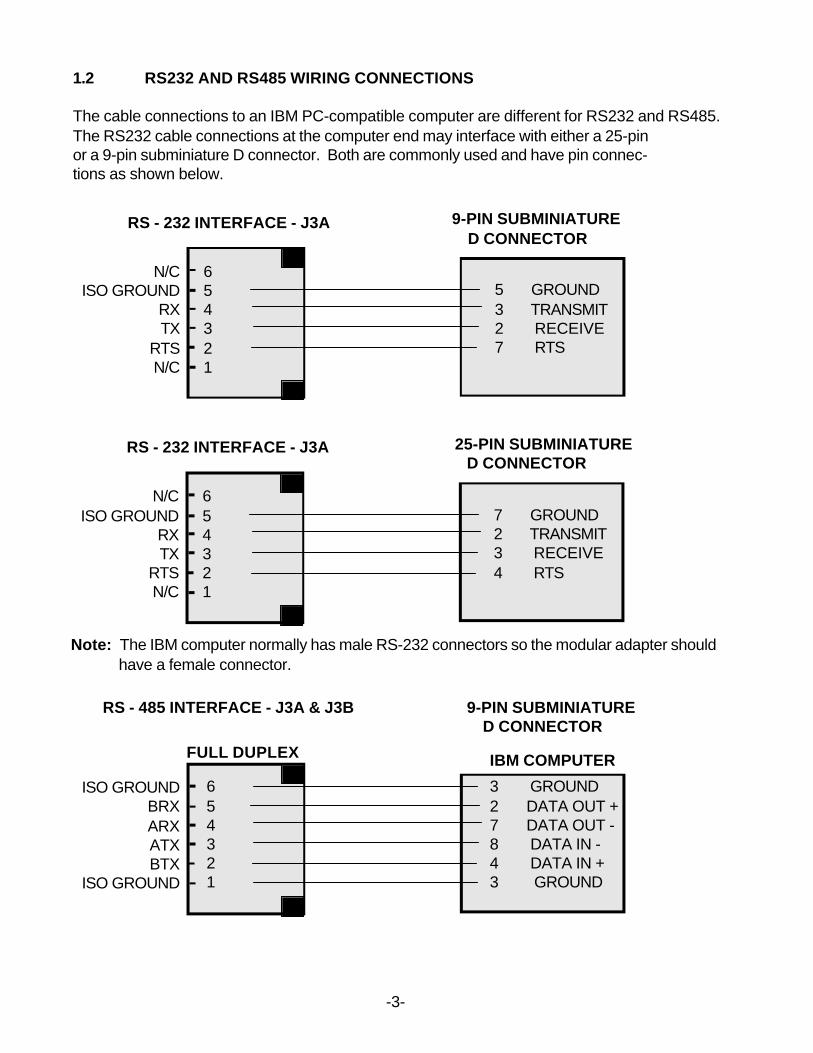
1.2 RS232 AND RS485 WIRING CONNECTIONS
The cable connections to an IBM PC-compatible computer are different for RS232 and RS485.The RS232 cable connections at the computer end may interface with either a 25-pinor a 9-pin subminiature D connector. Both are commonly used and have pin connec-tions as shown below.
RS - 232 INTERFACE - J3A
N/CISO GROUND
RXTX
RTSN/C
654321
9-PIN SUBMINIATURE D CONNECTOR
5 GROUND3 TRANSMIT2 RECEIVE7 RTS
RS - 232 INTERFACE - J3A
N/CISO GROUND
RXTX
RTSN/C
654321
25-PIN SUBMINIATURE D CONNECTOR
7 GROUND2 TRANSMIT3 RECEIVE4 RTS
Note: The IBM computer normally has male RS-232 connectors so the modular adapter shouldhave a female connector.
RS - 485 INTERFACE - J3A & J3B
FULL DUPLEX
ISO GROUNDBRXARX ATXBTX
ISO GROUND
654321
IBM COMPUTER
3 GROUND2 DATA OUT +7 DATA OUT -8 DATA IN -4 DATA IN +3 GROUND
9-PIN SUBMINIATURE D CONNECTOR
-3-
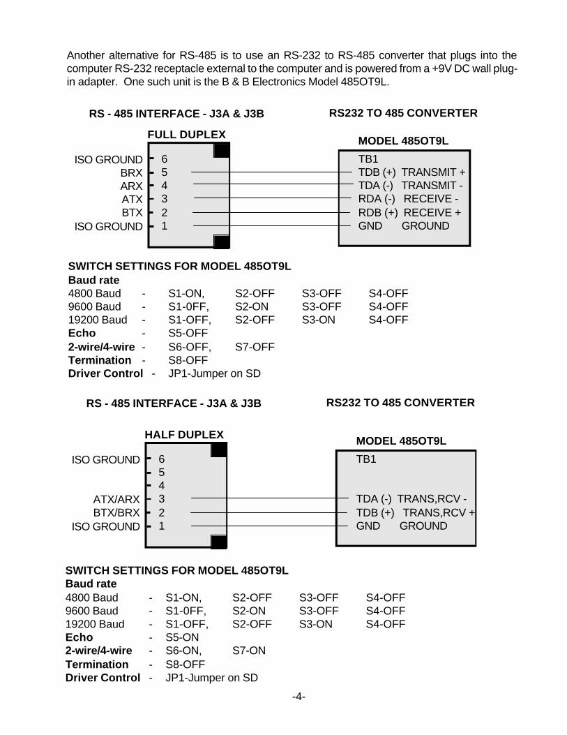
Another alternative for RS-485 is to use an RS-232 to RS-485 converter that plugs into thecomputer RS-232 receptacle external to the computer and is powered from a +9V DC wall plug-in adapter. One such unit is the B & B Electronics Model 485OT9L.
-4-
RS - 485 INTERFACE - J3A & J3B
FULL DUPLEX
ISO GROUNDBRXARX ATXBTX
ISO GROUND
654321
MODEL 485OT9L
TB1TDB (+) TRANSMIT +TDA (-) TRANSMIT -RDA (-) RECEIVE -RDB (+) RECEIVE +GND GROUND
RS232 TO 485 CONVERTER
SWITCH SETTINGS FOR MODEL 485OT9LBaud rate4800 Baud - S1-ON, S2-OFF S3-OFF S4-OFF9600 Baud - S1-0FF, S2-ON S3-OFF S4-OFF19200 Baud - S1-OFF, S2-OFF S3-ON S4-OFFEcho - S5-OFF2-wire/4-wire - S6-OFF, S7-OFFTermination - S8-OFFDriver Control - JP1-Jumper on SD
RS - 485 INTERFACE - J3A & J3B
HALF DUPLEX
ISO GROUND
ATX/ARXBTX/BRX
ISO GROUND
654321
MODEL 485OT9L
TB1
TDA (-) TRANS,RCV -TDB (+) TRANS,RCV +GND GROUND
RS232 TO 485 CONVERTER
SWITCH SETTINGS FOR MODEL 485OT9LBaud rate4800 Baud - S1-ON, S2-OFF S3-OFF S4-OFF9600 Baud - S1-0FF, S2-ON S3-OFF S4-OFF19200 Baud - S1-OFF, S2-OFF S3-ON S4-OFFEcho - S5-ON2-wire/4-wire - S6-ON, S7-ONTermination - S8-OFFDriver Control - JP1-Jumper on SD
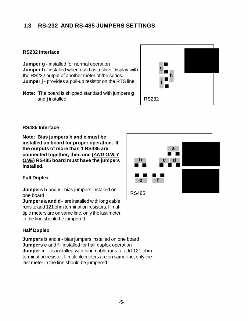
1.3 RS-232 AND RS-485 JUMPERS SETTINGS
RS232 Interface
Jumper g - installed for normal operationJumper h - installed when used as a slave display withthe RS232 output of another meter of the series.Jumper j - provides a pull-up resistor on the RTS line.
Note: The board is shipped standard with jumpers gand j installed RS232
RS485
RS485 Interface
h
g
j
a
dcb
fe
Note: Bias jumpers b and e must beinstalled on board for proper operation. Ifthe outputs of more than 1 RS485 areconnected together, then one (AND ONLYONE) RS485 board must have the jumpersinstalled.
Full Duplex
Jumpers b and e - bias jumpers installed onone boardJumpers a and d - are installed with long cableruns to add 121 ohm termination resistors. If mul-tiple meters are on same line, only the last meterin the line should be jumpered.
Half Duplex
Jumpers b and e - bias jumpers installed on one boardJumpers c and f - installed for half duplex operationJumper a - is installed with long cable runs to add 121 ohmtermination resistor. If multiple meters are on same line, only thelast meter in the line should be jumpered.
-5-
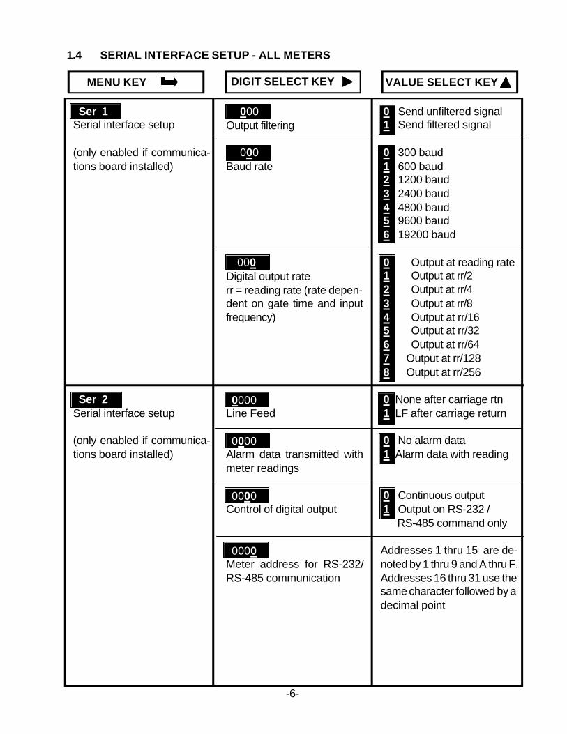
DIGIT SELECT KEY VALUE SELECT KEYMENU KEY
Ser 1Serial interface setup
(only enabled if communica-tions board installed)
Ser 2Serial interface setup
(only enabled if communica-tions board installed)
0 Send unfiltered signal 1 Send filtered signal
0 300 baud 1 600 baud 2 1200 baud 3 2400 baud 4 4800 baud 5 9600 baud 6 19200 baud
0 Output at reading rate 1 Output at rr/2 2 Output at rr/4 3 Output at rr/8 4 Output at rr/16 5 Output at rr/32 6 Output at rr/64 7 Output at rr/128 8 Output at rr/256
0 None after carriage rtn 1 LF after carriage return
0 No alarm data 1 Alarm data with reading
0 Continuous output 1 Output on RS-232 / RS-485 command only
Addresses 1 thru 15 are de-noted by 1 thru 9 and A thru F.Addresses 16 thru 31 use thesame character followed by adecimal point
000Output filtering
000Baud rate
000Digital output raterr = reading rate (rate depen-dent on gate time and inputfrequency)
0000Line Feed
0000Alarm data transmitted withmeter readings
0000Control of digital output
0000Meter address for RS-232/RS-485 communication
1.4 SERIAL INTERFACE SETUP - ALL METERS
-6-
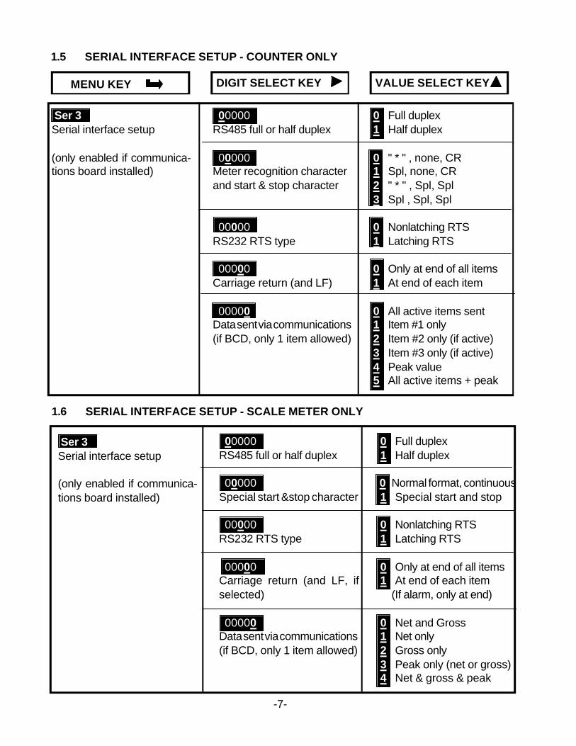
DIGIT SELECT KEY VALUE SELECT KEYMENU KEY
00000RS485 full or half duplex
00000Meter recognition characterand start & stop character
00000RS232 RTS type
00000Carriage return (and LF)
00000Data sent via communications(if BCD, only 1 item allowed)
Ser 3Serial interface setup
(only enabled if communica-tions board installed)
0 Full duplex 1 Half duplex
0 " * " , none, CR 1 Spl, none, CR 2 " * " , Spl, Spl 3 Spl , Spl, Spl
0 Nonlatching RTS 1 Latching RTS
0 Only at end of all items 1 At end of each item
0 All active items sent 1 Item #1 only 2 Item #2 only (if active) 3 Item #3 only (if active) 4 Peak value 5 All active items + peak
1.5 SERIAL INTERFACE SETUP - COUNTER ONLY
00000RS485 full or half duplex
00000Special start &stop character
00000RS232 RTS type
00000Carriage return (and LF, ifselected)
00000Data sent via communications(if BCD, only 1 item allowed)
Ser 3Serial interface setup
(only enabled if communica-tions board installed)
0 Full duplex 1 Half duplex
0 Normal format, continuous 1 Special start and stop
0 Nonlatching RTS 1 Latching RTS
0 Only at end of all items 1 At end of each item (If alarm, only at end)
0 Net and Gross 1 Net only 2 Gross only 3 Peak only (net or gross) 4 Net & gross & peak
1.6 SERIAL INTERFACE SETUP - SCALE METER ONLY
-7-
2.0 INTERFACE INFORMATION
The series of DPMs and counters offers RS232 or RS485 serial communication interface boardsthat may be connected by cable to computers, remote displays, printers or other digital deviceshaving similar serial communication capability. Software is available for use with an IBM-compatible PC/XT/AT computer that simplifies the logging of measurement data on the computerand provides capability for the remote setting of parameter values in lieu of using the front panelmenu setup.
3.0 RS232 AND RS485 FORMAT
3.1 SERIAL COMMUNICATION FORMAT
The serial communication format for both RS232 and RS485 is the following:Mode Full Duplex (Separate transmit and receive lines) and Half Duplex (RS485
only)Baud Rate 300, 600, 1200, 2400, 4800, 9600, 19200 selectable by front panel Menu
item “Ser 1”, Sub-menu item “Digit 4” for DPM, "Digit 5" for counter.Parity NoneWord length 8 data bitsStop bit 1
3.2 MEASUREMENT DATA FORMAT
The basic measurement data format consists of 8 ASCII characters:(shown for DPM, add 1 more digit for counter)
+999.99<cr> where <cr> is the carriage return character
Notes: The first character is always a plus or minus sign, and a decimal point is alwaysfurnished, even when it follows the last digit and is not required.
Adding a Line Feed Character to the Basic Format
Printers and other devices that receive the measurement data sometimes require a line feedcharacter <lf> following the carriage return character <cr>. The line feed may be selected in "Ser2"
Adding a Coded Data Character to the Basic Format
It is also possible to add a coded character to the data format to indicate the alarm, overload andzero-blanking status of the meter. If used, this character precedes the <cr> so it is the last printablecharacter in the format (<cr> and <lf> are control characters and are not printable). This codedcharacter may be selected in "Ser 2"
-8-
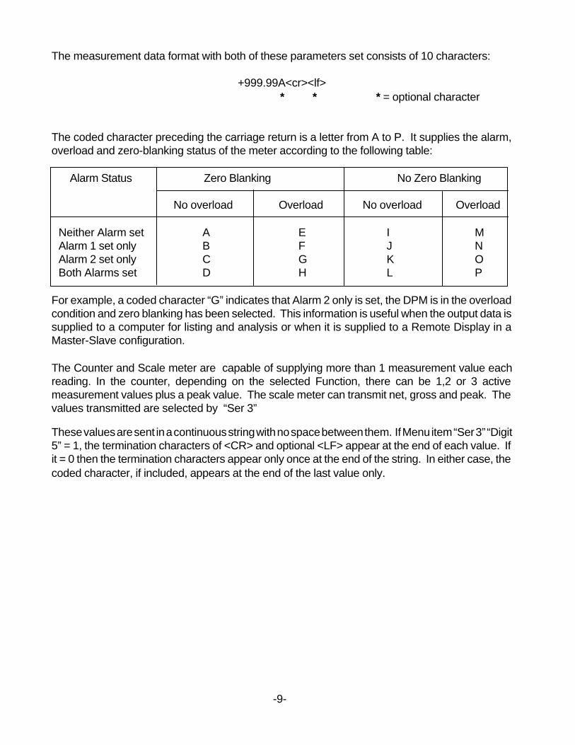
The measurement data format with both of these parameters set consists of 10 characters:
+999.99A<cr><lf> * * * = optional character
The coded character preceding the carriage return is a letter from A to P. It supplies the alarm,overload and zero-blanking status of the meter according to the following table:
Alarm Status Zero Blanking No Zero Blanking
No overload Overload No overload Overload
Neither Alarm set A E I MAlarm 1 set only B F J NAlarm 2 set only C G K OBoth Alarms set D H L P
For example, a coded character “G” indicates that Alarm 2 only is set, the DPM is in the overloadcondition and zero blanking has been selected. This information is useful when the output data issupplied to a computer for listing and analysis or when it is supplied to a Remote Display in aMaster-Slave configuration.
The Counter and Scale meter are capable of supplying more than 1 measurement value eachreading. In the counter, depending on the selected Function, there can be 1,2 or 3 activemeasurement values plus a peak value. The scale meter can transmit net, gross and peak. Thevalues transmitted are selected by “Ser 3”
These values are sent in a continuous string with no space between them. If Menu item “Ser 3” “Digit5” = 1, the termination characters of <CR> and optional <LF> appear at the end of each value. Ifit = 0 then the termination characters appear only once at the end of the string. In either case, thecoded character, if included, appears at the end of the last value only.
-9-
4.0 SYSTEM CONFIGURATIONS
The meters operate in a Point-to-point mode using RS-232 or RS-485. In addition, they canoperate in a Multi-point mode using RS-485.
Point-to-point mode is a direct connection between a computer or other digital device and themeter.
Multi-Point mode is a connection from a host computer to a multiplicity of meters bussed togetherwith their inputs and outputs connected in parallel. For long cable runs, the last meter should havethe termination resistors installed. It is necessary to set up each meter on the bus with a differentaddress from 1 to 31. To command a particular meter, its address is used in conjunction with thecommand and only that meter responds. The outputs of all of the meters on the bus are set to ahigh impedance state except the meter addressed. The meter addresses range from 1 to 31 with0 being a special address to which a meter responds only internally (e.g. Reset) but does nottransmit any response on the output lines. All meters may be commanded simultaneously witha 0 address and there will not be any output response contention. Addressing of the meters canbe set in “Ser 2”,A meter operating in a point-to-point mode must also be addressed. Although any address willsuffice, it is suggested address = 1 be selected as a standard for the point-to-point mode.
5.0 OPERATING MODES
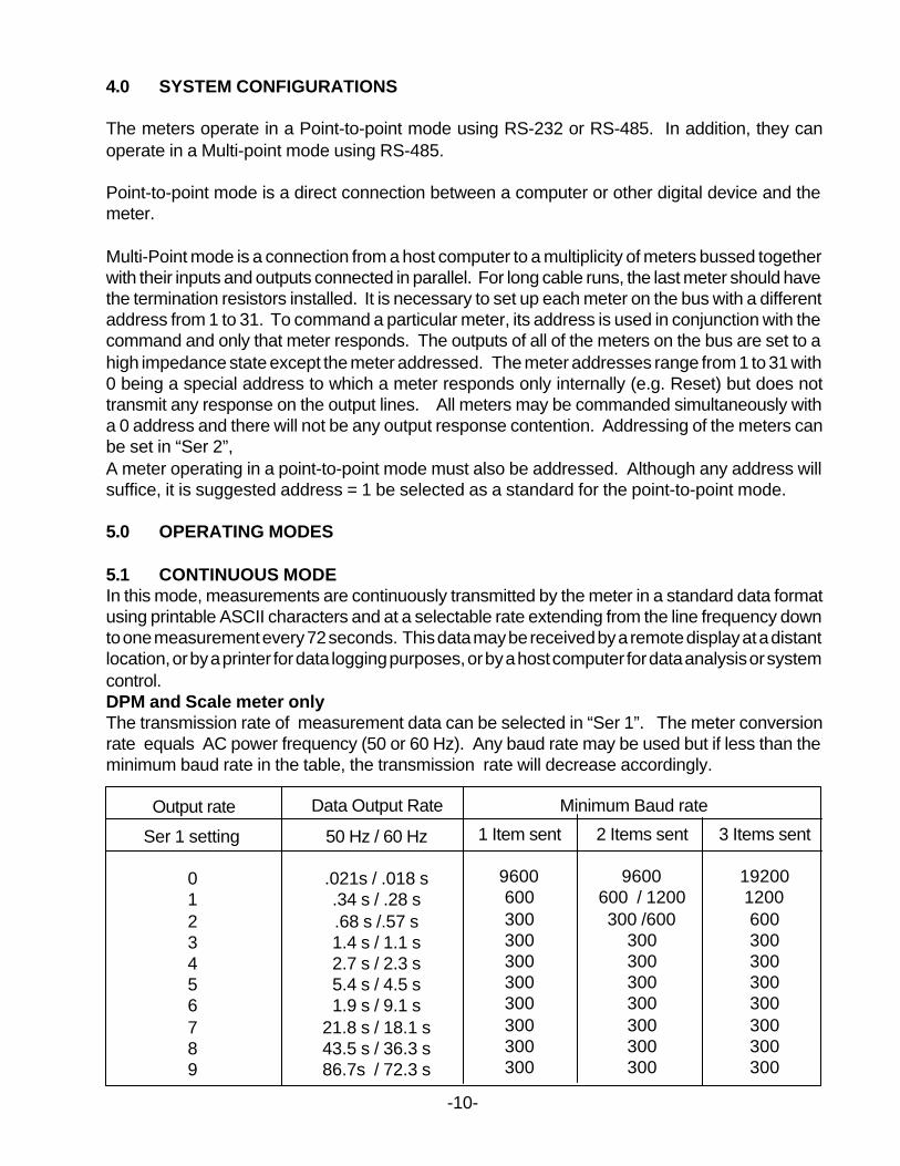
5.1 CONTINUOUS MODEIn this mode, measurements are continuously transmitted by the meter in a standard data formatusing printable ASCII characters and at a selectable rate extending from the line frequency downto one measurement every 72 seconds. This data may be received by a remote display at a distantlocation, or by a printer for data logging purposes, or by a host computer for data analysis or systemcontrol.DPM and Scale meter onlyThe transmission rate of measurement data can be selected in “Ser 1”. The meter conversionrate equals AC power frequency (50 or 60 Hz). Any baud rate may be used but if less than theminimum baud rate in the table, the transmission rate will decrease accordingly.
Output rate Minimum Baud rateData Output Rate
-10-
1 Item sent
9600600300300300300300300300300
2 Items sent
9600600 / 1200300 /600
300300300300300300300
3 Items sent
192001200600300300300300300300300
50 Hz / 60 Hz
.021s / .018 s.34 s / .28 s.68 s /.57 s1.4 s / 1.1 s2.7 s / 2.3 s5.4 s / 4.5 s1.9 s / 9.1 s
21.8 s / 18.1 s43.5 s / 36.3 s86.7s / 72.3 s
Ser 1 setting
0123456789
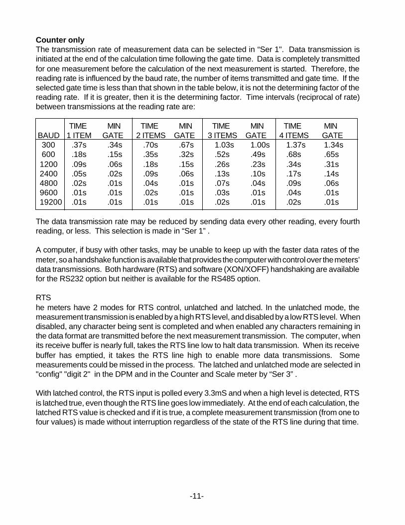
Counter onlyThe transmission rate of measurement data can be selected in “Ser 1". Data transmission isinitiated at the end of the calculation time following the gate time. Data is completely transmittedfor one measurement before the calculation of the next measurement is started. Therefore, thereading rate is influenced by the baud rate, the number of items transmitted and gate time. If theselected gate time is less than that shown in the table below, it is not the determining factor of thereading rate. If it is greater, then it is the determining factor. Time intervals (reciprocal of rate)between transmissions at the reading rate are:
TIME MIN TIME MIN TIME MIN TIME MIN BAUD 1 ITEM GATE 2 ITEMS GATE 3 ITEMS GATE 4 ITEMS GATE 300 .37s .34s .70s .67s 1.03s 1.00s 1.37s 1.34s 600 .18s .15s .35s .32s .52s .49s .68s .65s 1200 .09s .06s .18s .15s .26s .23s .34s .31s 2400 .05s .02s .09s .06s .13s .10s .17s .14s 4800 .02s .01s .04s .01s .07s .04s .09s .06s 9600 .01s .01s .02s .01s .03s .01s .04s .01s 19200 .01s .01s .01s .01s .02s .01s .02s .01s
The data transmission rate may be reduced by sending data every other reading, every fourthreading, or less. This selection is made in “Ser 1” .
A computer, if busy with other tasks, may be unable to keep up with the faster data rates of themeter, so a handshake function is available that provides the computer with control over the meters’data transmissions. Both hardware (RTS) and software (XON/XOFF) handshaking are availablefor the RS232 option but neither is available for the RS485 option.
RTShe meters have 2 modes for RTS control, unlatched and latched. In the unlatched mode, themeasurement transmission is enabled by a high RTS level, and disabled by a low RTS level. Whendisabled, any character being sent is completed and when enabled any characters remaining inthe data format are transmitted before the next measurement transmission. The computer, whenits receive buffer is nearly full, takes the RTS line low to halt data transmission. When its receivebuffer has emptied, it takes the RTS line high to enable more data transmissions. Somemeasurements could be missed in the process. The latched and unlatched mode are selected in"config" "digit 2" in the DPM and in the Counter and Scale meter by “Ser 3” .
With latched control, the RTS input is polled every 3.3mS and when a high level is detected, RTSis latched true, even though the RTS line goes low immediately. At the end of each calculation, thelatched RTS value is checked and if it is true, a complete measurement transmission (from one tofour values) is made without interruption regardless of the state of the RTS line during that time.
-11-
At the end of the complete transmission, the latched RTS value is reset false, even though the RTSline may be high at that instant. The RTS latch does not go true again until the RTS line is firstreturned to a low level after the completion of the transmission and then is taken high again. Latchedcontrol provides “print command” operation by sending a transmission for each RTS pulse. If asecond pulse occurs during the transmission, it is not recognized.
XON/XOFF
A measurement transmission is enabled by the receipt of an ASCII XON character, and disabledby the receipt of an ASCII XOFFcharacter.
COMMAND MODE
In this mode, the meter does not send any data automatically, but instead responds to commandsit receives from the host computer. These commands can be:
To transmit the latest or peak measurement,To reset itself completely or just the peak value and/or the latched alarms,To display a value sent from the computer,To transmit present setup parameters,To receive new setup parameters, andTo monitor or alter data in selected memory locations of the meter.
The selection of either the Continuous mode or the Command mode can be made from the frontpanel Menu selection “Ser 2”,Note: The meter will not respond to a command in the Continuous mode except the command “A1”
which puts the meter into the Command mode.
5.2 COMMAND MODE FORMAT
The command mode formats are required only by those users desiring to write custom softwarefor reading or controlling the meter or changing setup parameters. Software is available that iseasy to use and doesn’t require programming for those that can accept the format in which it ispresented. For those wishing to do their own custom programming using the meter’s commands,the following information lists the commands and their format.
Note (for the Counter only): After any command that causes a Meter Reset such as C0, F, W,X, the Counter sends an “R” character after the Reset is complete and the Counter isready to accept a new command.
The minimum format is 4 characters:Example: *5A1
CHAR 1 - COMMAND IDENTIFIER
All commands begin with “*” followed by the meter address, then a command letter followed by asub-command number or letter. Additional characters may be appended. All commands terminatewith <cr> (<lf> ignored). The counter may be assigned a different recognition character via theRS232/485 serial port but will still recognize the “*”
-12-
CHAR #
12
34
CHARACTER
*0-V
A-Z0-U
DESCRIPTION
Command Identifier (Recognition Character)Device Address (0 addresses all devices, 1-Vspecific)Command FunctionSub-command (or # Bytes or Words of data beingtransferred)
CHAR 2 - ADDRESS CODES
The next table is the Serial Communication Address Codes following the “*” for each meteraddress number. Also shown is the corresponding character that is set in menu item “SER 2”,
Menu MenuSER 2 Serial Comm SER 2 Serial Comm
Meter # Digit 5(6) Address Code Meter # Digit 5(6) Address Code
1 1 1 16 0. G2 2 2 17 1. H3 3 3 18 2. I4 4 4 19 3. J5 5 5 20 4. K6 6 6 21 5. L7 7 7 22 6. M8 8 8 23 7. N9 9 9 24 8. O
10 A A 25 9. P11 B B 26 A. Q12 C C 27 B. R13 D D 28 C. S14 E E 29 D. T15 F F 30 E. U
31 F. V
CHARS 3 & 4 - COMMANDS AND SUBCOMMANDS
The examples below use a default address of 1 following the “ *”. Substitute the desired addressfrom the above table of Serial Comm Address Codes. All command sequences shown mustterminate with <CR> (followed by an optional <lf>.
-13-
-14-
COMMUNICATIONS MODEContinuous mode *1A0Command mode *1A1
. REQUEST DPM/SCALE VALUE REQUEST COUNTER VALUESLatest reading *1B1 * All active items *1B0Peak value *1B2 Item 1 *1B1
Item 2 *1B2* - The scale meter transmits Item 3 *1B3the value or values selected Peak *1B4in Ser 3 All active items + peak *1B5
RESET FUNCTIONS -DPM AND SCALE METERCold reset *1C0 (Reads NVMEM into RAM locations after RAM zeroed)Warm reset *1C1 (RAM undisturbed but program initialized)Latched alarms reset *1C2Peak value reset *1C3Remote display reset *1C4
RESET FUNCTIONS -COUNTERCold reset *1C0 (Reads NVMEM into RAM locations after RAM zeroed)Function reset *1C1 (Resets all total values and/or peak value)Latched alarms reset *1C2Peak value reset *1C3Remote display reset *1C4 (Resets Item 3 to zero ( if not Arith or Batch) and
removes Alarm View or Peak View if on)External Input B true *1C5External Input B false *1C6
5.3 READ AND WRITE TO RAM AND NONVOLATILE MEMORY
CHARACTER 1 AND 2
The Recognition character and Meter Address Code is the same as address codes shown inprevious table
CHARACTER 3
Command characterG Read bytes from RAM MemoryF Write bytes to RAM Memory (DPM and Scale meter only)X Read words from Non-Volatile MemoryW Write words to Non-Volatile Memory
CHARACTER 4
Code for number of bytes or words
Code # Code # Code # Code #1 = 1 9 = 9 H = 17 P = 252 = 2 A = 10 I = 18 Q = 263 = 3 B = 11 J = 19 R = 274 = 4 C = 12 K = 20 S = 285 = 5 D = 13 L = 21 T = 296 = 6 E = 14 M = 22 U = 307 = 7 F = 15 N = 238 = 8 G = 16 O = 24
CHARACTERS 5,6
See tables in Section 6 for the RAM MEMORY ADDRESSES and NONVOLATILE MEMORYADDRESSES with their respective data definitions.
(1) READ AND WRITE RAM MEMORY DATA
RAM memory data is read and written as a continuous string of bytes consisting of 2 hexcharacters (0-9,A-F) per byte. Included in the command is the total number of bytes to betransferred and the most significant address in RAM of the continuous string of bytes. Theformat is:
Read RAM data *1GnaaWrite RAM data *1Fnaa<data>where: n is the number of bytes to be read or written.aa is the most significant address in RAM of the bytes to be read or written.data is n bytes of 2 hex characters per byte in order from the most to the least significant
byte.The number of bytes n consists of a single code character representing values from 1 to 30as shown above under CHARACTER 4.The most significant address aa consists of 2 hex characters as shown below under RAMMEMORY ADDRESSES AND DATA DEFINITIONS.
(2) READ AND WRITE NONVOLATILE MEMORY DATA
Nonvolatile data is read and written as a continuous string of words consisting of 2bytes or 4 hex characters (0-9,A-F) per word. Included in the command is the totalnumber of words to be transferred and the most significant address in nonvolatilememory of the continuous string of words. The format is:
Read nonvolatile memory data - *1Xnaa (followed by Meter reset)Write non-volatile memory data - *1Wnaa <data> (followed by Meter reset)where: n is the number of words to be read or written.
-15-
aa is the most significant address in nonvolatile memory of the wordsto be read or written
<data> is n words of 2 bytes or 4 hex characters per word in order fromthe most to the least significant address
The coded number of words n consists of a single character representing values from 1to 30 as shown under CHARACTER 4.The most significant address aa consists of 2 hex characters as shown under NON-VOLATILE MEMORY ADDRESSES.
5.4 REMOTE DISPLAY COMMAND FORMAT
5.4.1. DPMDATA FORMAT
*1HSDDDDD.A S = Sign, either blank (for +) or -D = Digit from 0 to 9, five digits total. Always include adecimal point even though it comes at the end.A = Alarm character as defined in 3.2.
REMOTE DISPLAY
A DPM may serve as a remote display that responds to values sent by a PCController (E.G. an IBM PC/XT/AT personal computer) with serial communicationsor to another DPM in a Master/Slave configuration. There are 3 modes in which theDPM may act as a remote display.
MODE 1DPM with Signal Conditioner card and not in Remote Display mode.
SETUP (left digit) = 0 4 1/2 Digit DPM= 2 4 1/2 Digit DPM with Count by 10= 3 3 1/2 Digit DPM
The baud rate must be set the same as the source. The PC Controller uses the Hcommand to cause the display to halt it’s normal readings and display the value sentby Serial Communications instead. The DPM must be in the Command mode toreceive the data. The data format sent via Serial Communications is:
*#HSDDDDD.A <CR> where the decimal point is in front, behind (as shown),or between the D’s (digits).
An exact total of 11 characters plus a CR must be included and sent as ASCIIcharacters. Those in quotes below are included as shown. The other symbolsrepresent a range of characters except for CR which is the ASCII character “0D”.
* = Command identifier # = Device address from 1 to 9, A to V, or 0 for common address H = Command letter
-16-
S = Sign of value, space (or +) for positive, - for neg value D = Digit from 0 to 9 . = Decimal point placement and must always be included A = Alarm and overload character code, A to H<CR> = Carriage return character
The following table lists the Alarm and Overload characters.
ALARM CONDITION NO OVERLOAD OVERLOAD
Neither Alarm on A EAlarm 1 only on B FAlarm 2 only on C GAlarms 1 & 2 on D H
If the DPM is in the Continuous mode, it must be put into the Command mode bysending *#A1 prior to sending the remote display value.The Remote Display value remains on the display until one of the following occur-rences:a. The command *#C4 is sent removing the Remote Display value and
returning to the normal readings without resetting the DPM.b. The command *#C0 is sent causing a Cold Reset of the DPM.c. The command *#C1 is sent causing a Warm Reset of the DPM.d. Front panel pushbuttons RESET and MENU are simultaneously pushed to
cause a Cold Reset of the DPM.
Notes:After the Remote Display value is entered, the DPM can be put back in theContinuous mode with the command *#A0 without disturbing the display’s value.DPM must be in the Command mode for a., b., or c. above. It may be put into theCommand mode while displaying a remote display value with the *1A1 commandwithout affecting the display.If PEAK (manual or external) or ALARM VIEW (manual) is activated while the remotevalue is being displayed, the peak or alarm value is displayed and cannot beremoved except by Remote Display Reset (a., b., or c. above in Command mode)or by manual RESET. If a Remote Display value is sent while in PEAK or ALARMVIEW, it is ignored, but when PEAK or ALARM VIEW is turned off, the RemoteDisplay value comes on.
MODE 2DPM with Signal Conditioner card and in Remote Display mode.
SETUP (left digit) = 1 Remote Display modeThe baud rate must be set the same as the source which may be a PC Controller oranother DPM.
The format is the Slave Format. This is the same as MODE 1 above but without the
-17-
Command Identifier “*”, the address #, and the Command letter “H”. This is thesame format that data is transmitted from a DPM in the Continuous mode. The stringof characters must be exactly 8 characters plus the CR in length.
SDDDDD.A <CR>
No commands can be received in this mode but the front panel MENU can beaccessed. Any transmissions received other than properly formatted data will resultin a meaningless display. Alarm setpoints, Peak readings and external controlfunctions are disabled while the Remote Display value is being displayed. When theDPM is Reset, it displays RESET continuously until data is received.
5.4.2. COUNTERThe Counter has 13 Display Modes (0-12). Modes 0-5 are normal measurementmodes and Modes 6-12 are dedicated to Remote Display only without making anynormal readings. In any of the 12 modes, remote display data may be received viaRS-232 or RS-485 serial communications and displayed. The remote datarequirements and the Remote Display capabilities vary for the different displaymodes and selected Input Functions. The mode is selected by Menu item “ConFiG”“Digit 3” from the following list.
Normal Readings While Displaying Remote Data Addressable Commands0 Normal display, Exponent Overflow H,K or L1 Normal display, 999999 Overflow H,K or L2 1 Right-hand dummy zero H,K or L3 2 Right-hand dummy zeros H,K or L4 Real time clock, multi-format H,K or L5 Real time clock, hh.mm,ss H,K or L
Remote Display Only - No Normal Readings Addressable Commands6 Addressable remote display H,K or L commands7 Single value remote display 1 Value only8 1st value of value sequence 1-4 sequential Values9 2nd value of value sequence 2-4 sequential ValuesA 3rd value of value sequence 3-4 sequential ValuesB 4th value of value sequence 4 sequential ValuesC Programmed to select specific data 1 Value only
from a data string
The addressable commands of Modes 0-6 can display remote data on one or moreCounters having the command address in a multi-point configuration or a singleCounter having the command address in a Point-to-point configuration. Modes 7 -11 (B) do not use addressable commands, but values only. They are primarilydesigned for Host Counter or Scale meter to Slave Counter or remote displayapplications but may be used also in Host Computer to Remote Display Counterconfigurations. Since the Host Counter may be selected to transmit up to foursequential measurement values, Item 1, Item 2, Item 3 and Peak, (Scale meter
-18-
transmits up to 3 values) each measurement cycle, Modes 8-11 provide the abilityof the Remote Display to extract one of four sequential values and display it.
Modes 0-5 are normal counter modes that may be commanded as follows:1. H Command. Override the normal display reading only.2. K Command. The value is not displayed but stored as Item 3 if Item 3 is not
being used, where it may become the source, if selected, for the Alarmcomparison and the Analog Output. Item 3 is used only for the Batch andArithmetic functions.
3. L Command. Both 1 and 2.
In addition, the H, K, L commands may or may not include a coded Alarm character.If included, it always overrides the internal Alarm comparisons and determines thealarm indicators, the relay operation and the alarm character sent with the serialcommunications. Readings continue to be made internally during Remote Displayoperation and may be received by a Host Computer, manipulated, and returned asremote data. When reset by a *1C4 Command, the display returns to its internalreadings, the Alarms to its internal comparisons, the Analog Output to zero and theItem 3 value to zero. A signal conditioner board must be present in these modes toreturn to normal readings. If no signal conditioner board is present, any Mode settingfrom 0-5 automatically changes to Mode 6.
Modes 6-11 are used for remote display only. No normal readings are made. Asignal conditioner board is optional, and if present, is ignored. When reset, thedisplay shows “rESEt” until the first remote display data is received.
Mode 6 is an addressable remote display mode that uses the H, K, L commands.Mode 7 is not addressable and data representing a value to be displayed isreceived in a Pt-Pt connection. Besides displaying the value, it is put into Item 3where it may be selected for Alarm comparisons and for Analog Output. If a CodedAlarm character is included it overrides the internal alarm comparisons.
Modes 8-11 are able to extract one value of data from a sequence of values anddisplay that particular value only. It could be one of several slave counters connectedto a Host Counter, each displaying a different Item value. Also, the extracted valueis put into Item 3 where it may be selected for Alarm comparisons and Analog Output.If a Coded Alarm character is included at the end of the sequence, it is ignored.
The remote display reading can only be changed by Meter Reset, a *1C4 Remotedisplay reset command or another remote display H or L command.
DATA FORMATSThe basic two Command formats of the data sent via Serial Communications are:
*#CSDDDDDD.A<CR><LF> where the decimal point is to the right of any one ofthe D’s (digits).
*#CSD.DDDEPA<CR><LF> this is the exponential format. The decimal point isfixed. Alarm comparison and Analog Output are not valid in this format.
-19-
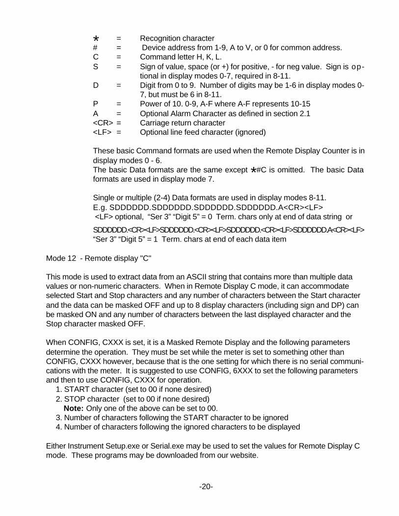
* = Recognition character# = Device address from 1-9, A to V, or 0 for common address.C = Command letter H, K, L.S = Sign of value, space (or +) for positive, - for neg value. Sign is op-
tional in display modes 0-7, required in 8-11.D = Digit from 0 to 9. Number of digits may be 1-6 in display modes 0-
7, but must be 6 in 8-11.P = Power of 10. 0-9, A-F where A-F represents 10-15A = Optional Alarm Character as defined in section 2.1<CR> = Carriage return character<LF> = Optional line feed character (ignored)
These basic Command formats are used when the Remote Display Counter is indisplay modes 0 - 6.The basic Data formats are the same except *#C is omitted. The basic Dataformats are used in display mode 7.
Single or multiple (2-4) Data formats are used in display modes 8-11.E.g. SDDDDDD.SDDDDDD.SDDDDDD.SDDDDDD.A<CR><LF> <LF> optional, “Ser 3” “Digit 5” = 0 Term. chars only at end of data string or
SDDDDDD.<CR><LF>SDDDDDD.<CR><LF>SDDDDDD.<CR><LF>SDDDDDD.A<CR><LF>“Ser 3” “Digit 5” = 1 Term. chars at end of each data item
Mode 12 - Remote display "C"
This mode is used to extract data from an ASCII string that contains more than multiple datavalues or non-numeric characters. When in Remote Display C mode, it can accommodateselected Start and Stop characters and any number of characters between the Start characterand the data can be masked OFF and up to 8 display characters (including sign and DP) canbe masked ON and any number of characters between the last displayed character and theStop character masked OFF.
When CONFIG, CXXX is set, it is a Masked Remote Display and the following parametersdetermine the operation. They must be set while the meter is set to something other thanCONFIG, CXXX however, because that is the one setting for which there is no serial communi-cations with the meter. It is suggested to use CONFIG, 6XXX to set the following parametersand then to use CONFIG, CXXX for operation. 1. START character (set to 00 if none desired) 2. STOP character (set to 00 if none desired) Note: Only one of the above can be set to 00. 3. Number of characters following the START character to be ignored 4. Number of characters following the ignored characters to be displayed
Either Instrument Setup.exe or Serial.exe may be used to set the values for Remote Display Cmode. These programs may be downloaded from our website.
-20-
-21-
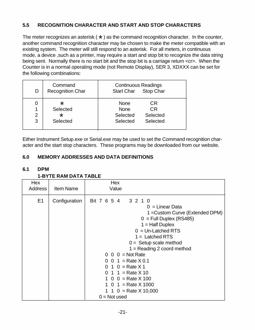
5.5 RECOGNITION CHARACTER AND START AND STOP CHARACTERS
The meter recognizes an asterisk ( * ) as the command recognition character. In the counter,another command recognition character may be chosen to make the meter compatible with anexisting system. The meter will still respond to an asterisk. For all meters, in continuousmode, a device ,such as a printer, may require a start and stop bit to recognize the data stringbeing sent. Normally there is no start bit and the stop bit is a carriage return <cr>. When theCounter is in a normal operating mode (not Remote Display), SER 3, XDXXX can be set forthe following combinations:
Command Continuous Readings D Recognition Char Start Char Stop Char
0 * None CR 1 Selected None CR 2 * Selected Selected 3 Selected Selected Selected
Either Instrument Setup.exe or Serial.exe may be used to set the Command recognition char-acter and the start stop characters. These programs may be downloaded from our website.
6.0 MEMORY ADDRESSES AND DATA DEFINITIONS
6.1 DPM1-BYTE RAM DATA TABLE
Hex Hex Address Item Name Value
E1 Configuration Bit 7 6 5 4 3 2 1 00 = Linear Data1 =Custom Curve (Extended DPM)
0 = Full Duplex (RS485)1 = Half Duplex
0 = Un-Latched RTS1 = Latched RTS
0 = Setup scale method1 = Reading 2 coord method
0 0 0 = Not Rate0 0 1 = Rate X 0.10 1 0 = Rate X 10 1 1 = Rate X 101 0 0 = Rate X 1001 0 1 = Rate X 10001 1 0 = Rate X 10,000
0 = Not used
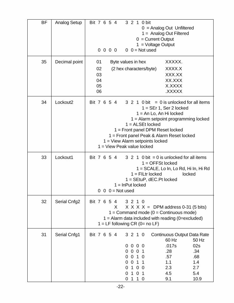
BF Analog Setup Bit 7 6 5 4 3 2 1 0 bit0 = Analog Out Unfiltered1 = Analog Out Filtered
0 = Current Output1 = Voltage Output
0 0 0 0 0 0 = Not used
35 Decimal point 01 Byte values in hex XXXXX.02 (2 hex characters/byte) XXXX.X03 XXX.XX04 XX.XXX05 X.XXXX06 .XXXXX
34 Lockout2 Bit 7 6 5 4 3 2 1 0 bit = 0 is unlocked for all items1 = SEr 1, Ser 2 locked
1 = An Lo, An Hi locked1 = Alarm setpoint programming locked
1 = ALSEt locked1 = Front panel DPM Reset locked
1 = Front panel Peak & Alarm Reset locked1 = View Alarm setpoints locked
1 = View Peak value locked
33 Lockout1 Bit 7 6 5 4 3 2 1 0 bit = 0 is unlocked for all items1 = OFFSt locked
1 = SCALE, Lo In, Lo Rd, Hi In, Hi Rd1 = FILtr locked locked
1 = SEtuP, dEC.Pt locked1 = InPut locked
0 0 0 = Not used
32 Serial Cnfg2 Bit 7 6 5 4 3 2 1 0X X X X X = DPM address 0-31 (5 bits)
1 = Command mode (0 = Continuous mode)1 = Alarm data included with reading (0=excluded)
1 = LF following CR (0= no LF)
31 Serial Cnfg1 Bit 7 6 5 4 3 2 1 0 Continuous Output Data Rate60 Hz 50 Hz
0 0 0 0 .017s 02s0 0 0 1 .28 .340 0 1 0 .57 .680 0 1 1 1.1 1.40 1 0 0 2.3 2.70 1 0 1 4.5 5.40 1 1 0 9.1 10.9
-22-
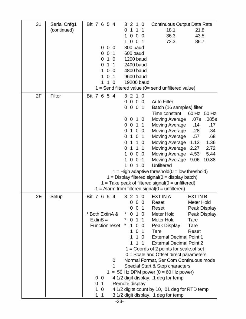
-23-
31 Serial Cnfg1 Bit 7 6 5 4 3 2 1 0 Continuous Output Data Rate(continued) 0 1 1 1 18.1 21.8
1 0 0 0 36.3 43.51 0 0 1 72.3 86.7
0 0 0 300 baud0 0 1 600 baud0 1 0 1200 baud0 1 1 2400 baud1 0 0 4800 baud1 0 1 9600 baud1 1 0 19200 baud
1 = Send filtered value (0= send unfiltered value)
2F Filter Bit 7 6 5 4 3 2 1 00 0 0 0 Auto Filter0 0 0 1 Batch (16 samples) filter
Time constant 60 Hz 50 Hz0 0 1 0 Moving Average .07s .085s0 0 1 1 Moving Average .14 .170 1 0 0 Moving Average .28 .340 1 0 1 Moving Average .57 .680 1 1 0 Moving Average 1.13 1.360 1 1 1 Moving Average 2.27 2.721 0 0 0 Moving Average 4.53 5.441 0 0 1 Moving Average 9.06 10.881 0 1 0 Unfiltered
1 = High adaptive threshold(0 = low threshold)1 = Display filtered signal(0 = display batch)
1 = Take peak of filtered signal(0 = unfiltered)1 = Alarm from filtered signal(0 = unfiltered)
2E Setup Bit 7 6 5 4 3 2 1 0 EXT IN A EXT IN B0 0 0 Reset Meter Hold0 0 1 Reset Peak Display
* Both ExtinA & * 0 1 0 Meter Hold Peak Display ExtinB = * 0 1 1 Meter Hold Tare Function reset * 1 0 0 Peak Display Tare
1 0 1 Tare Reset1 1 0 External Decimal Point 11 1 1 External Decimal Point 2
1 = Coords of 2 points for scale,offset 0 = Scale and Offset direct parameters
0 Normal Format, Ser Com Continuous mode1 Special Start & Stop characters
1 = 50 Hz DPM power (0 = 60 Hz power)0 0 4 1/2 digit display, .1 deg for temp0 1 Remote display1 0 4 1/2 digits count by 10, .01 deg for RTD temp1 1 3 1/2 digit display, 1 deg for temp
-24 -
2C Alarm Cnfg2 Bit 7 6 5 4 3 2 1 0 Alarm Trigger Delay60 Hz 50Hz
0 0 0 .018s .021s0 0 1 .035 .0430 1 0 .07 .0850 1 1 .14 .171 0 0 .28 .341 0 1 .56 .681 1 0 1.13 1.361 1 1 2.27 2.72
0 0 0 AL1 Band Dev, AL2 Band Dev0 0 1 AL1 Hysteres, AL2 Band Dev0 1 0 AL1 Band Dev, AL2 Hysteresys0 1 1 AL1 Hysteresys, AL2 Hysteresys1 0 0 No deviatn in menu or calc
2B Alarm Cnfg1 Bit 7 6 5 4 3 2 1 00 0 0 0 AL1 hi activ, AL2 hi activ0 0 0 1 AL1 lo activ, AL2 hi activ0 0 1 0 AL1 disabled, AL2 hi activ0 1 0 0 AL1 hi activ, AL2 lo activ0 1 0 1 AL1 lo activ, AL2 lo activ0 1 1 0 AL1 disabled, AL2 lo activ1 0 0 0 AL1 hi activ, AL2 disabled1 0 0 1 AL1 lo activ, AL2 disabled1 0 1 0 AL1 disabled, AL2 disabled
0 0 AL1 non-latch, AL2 non-latch0 1 AL1 latch, AL2 non-latch1 0 AL1 non-latch, AL2 latch1 1 AL1 latch, AL2 latch
0 0 Relay 1 ON, Relay 2 ON0 1 Relay 1 OFF, Relay 2 ON1 0 Relay 1 ON, Relay 2 OFF1 1 Relay 1 OFF, Relay 2 OFF
3-BYTE RAM MEMORY DATA
All items except Scale Factor use this format:Note: Hex value (2's complement) MS byte Mid byte LS byte
X X X X X X Scale factor uses this format: MS byte Mid byte LS byte
MS Nibble *(Polarity and Decimal Point) * X X X X X Positive 1 Negative 9 (Decimal point XXXXX.)
2 A (Decimal point XXXX.X)3 B (Decimal point XXX.XX)4 C (Decimal point XX.XXX)5 D (Decimal point X.XXXX)
Note: Hex value (Absolute value) 6 E (Decimal point .XXXXX)
RAM HEX DATA TABLE
MS Mid LSA1 A0 9F Analog high value9E 9D 9C Analog low value9B 9A 99 Deviation Alarm298 97 96 Deviation Alarm18F 8E 8D Offset value8C 8B 8A Scale factor89 88 87 Setpoint 286 85 84 Setpoint 1
NONVOLATILE MEMORY ADDRESSES (2 bytes/address)
See the corresponding itemsin RAM for data significance.
Address Most Significant Byte Least Significant Byte
18 Deviation2 3 Deviation2 217 Deviation2 1 Deviation1 316 Deviation1 2 Deviation1 115 Configuration SC Type (Do not change)14 Analog Setup System Decimal Point13 Lockout 2 Lockout 112 Serial Cnfg 2 Serial Cnfg 111 Options Filter10 Setup Input Type0F Alarm Cnfg 2 Alarm Cnfg 10E Analog High 3 Analog High 20D Analog High 1 Analog Low 30C Analog Low 2 Analog Low 10B High Reading 3 High Reading 20A High Reading 1 High Input 309 High Input 2 High Input 108 Low Reading 3 Low Reading 207 Low Reading 1 Low Input 306 Low Input 2 Low Input 105 Offset 3 Offset 204 Offset 1 Scale Factor 303 Scale Factor 2 Scale Factor 102 Setpoint2 3 Setpoint2 201 Setpoint2 1 Setpoint1 300 Setpoint1 2 Setpoint1 1
-25 -
6.2 COUNTER
1-BYTE RAM DATA TABLE
Hex Address Name Bit Assignment
43 Resolution Bit 7 6 5 4 3 2 1 00 0.00001 multiplier1 0.0001 multiplier
1 0 0.001 multiplier1 1 0.01 multiplier
1 0 0 0.11 0 1 11 1 0 101 1 1 100
1 0 0 0 10001 0 0 1 100001 0 1 0 100000
42 Recog char Ascii Value of custom Recognition Character
41 Slope Bit 7 6 5 4 3 2 1 0 bit = 0 is positive slope1 = negative slope Channel B
1 = negative slope Channel A
3E Scale multiplier Bits 3-0 = 0-A SCALE1 multiplierBits 7-4 = 0-A SCALE2 multiplier
0-A Same as Resolutn above
3D Analog setup Bit 7 6 5 4 3 2 1 0 Analog Output Source0 0 Filtered Item0 1 Item 11 0 Item 21 1 Item 3
1 Analog voltage out (0 = current out)
3C Source Bit 7 6 5 4 3 2 1 0 Compare Setpoint 2 to0 0 Filtered Item0 1 Item 11 0 Item 21 1 Item 3
Compare Setpoint 1 to0 0 Filtered Item0 1 Item 11 0 Item 21 1 Item 3
-26-
-27-
36 Lockout2 Bit 7 6 5 4 3 2 1 0 Bit=0 is unlocked for all items1 Change Item # locked
1 CALib locked1 Ser 1, Ser 2, Ser 3 locked
1 An Lo, An Hi, An SEt locked1 Front Panel meter reset locked
1 Front Panel Peak, Latched resets locked1 View alarm setpoints locked
1 View Peak locked
35 Lockout1 Bit 7 6 5 4 3 2 1 0 Bit=0 is unlocked for all items1 FiLtEr locked
1 Gate t, ti out, batch, pulses locked1 SEtuP, ConFiG locked
1 InPut locked1 Change Setpoints locked
1 SourcE,AL SEt,dEVn1b,1H,2b,2H locked1 SCALE,OFFSEt,Coords,rESoLn locked
1 SLOPE,dECPt locked
34 Configuration Bit 7 6 5 4 3 2 1 00 Sample time total zero cutoff1 Sample ti total allow negative
0 Linear input1 Square Root of input
0 0 Basic Counter0 1 Extended Counter1 0 Extended Counter, Custom curve #1
Display mode 1 1 Extended Cnr, Custom curve #2 (VF)0 0 0 0 Normal, Exponential Overload0 0 0 1 Normal, 999999 Flashing Overload0 0 1 0 1 Right-Hand dummy zero0 0 1 1 2 Right-Hand dummy zeros0 1 0 0 Clock Time, Stopwatch, Multi-format0 1 0 1 Clock Time, Stopwatch, hhmmss0 1 1 0 Remote Display, Addressable0 1 1 1 Remote Display, Single Value1 0 0 0 Slave Display, 1st data value of string1 0 0 1 Slave Display, 2nd data value of string1 0 1 0 Slave Display, 3rd data value of string1 0 1 1 Slave Display, 4th data value of string1 1 0 0 Masked display
33 Serial Cnfg3 Bit 7 6 5 4 3 2 1 0 Transmit0 0 0 All active items0 0 1 Item #1 only0 1 0 Item #2 only0 1 1 Item #3 only
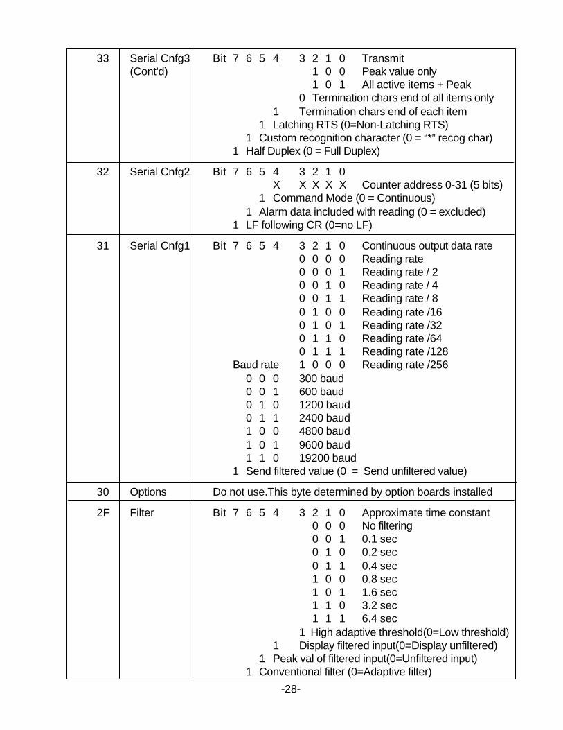
-28-
33 Serial Cnfg3 Bit 7 6 5 4 3 2 1 0 Transmit(Cont'd) 1 0 0 Peak value only
1 0 1 All active items + Peak0 Termination chars end of all items only
1 Termination chars end of each item1 Latching RTS (0=Non-Latching RTS)
1 Custom recognition character (0 = “*” recog char)1 Half Duplex (0 = Full Duplex)
32 Serial Cnfg2 Bit 7 6 5 4 3 2 1 0X X X X X Counter address 0-31 (5 bits)
1 Command Mode (0 = Continuous)1 Alarm data included with reading (0 = excluded)
1 LF following CR (0=no LF)
31 Serial Cnfg1 Bit 7 6 5 4 3 2 1 0 Continuous output data rate0 0 0 0 Reading rate0 0 0 1 Reading rate / 20 0 1 0 Reading rate / 40 0 1 1 Reading rate / 80 1 0 0 Reading rate /160 1 0 1 Reading rate /320 1 1 0 Reading rate /640 1 1 1 Reading rate /128
Baud rate 1 0 0 0 Reading rate /2560 0 0 300 baud0 0 1 600 baud0 1 0 1200 baud0 1 1 2400 baud1 0 0 4800 baud1 0 1 9600 baud1 1 0 19200 baud
1 Send filtered value (0 = Send unfiltered value)
30 Options Do not use.This byte determined by option boards installed
2F Filter Bit 7 6 5 4 3 2 1 0 Approximate time constant0 0 0 No filtering0 0 1 0.1 sec0 1 0 0.2 sec0 1 1 0.4 sec1 0 0 0.8 sec1 0 1 1.6 sec1 1 0 3.2 sec1 1 1 6.4 sec
1 High adaptive threshold(0=Low threshold)1 Display filtered input(0=Display unfiltered)
1 Peak val of filtered input(0=Unfiltered input)1 Conventional filter (0=Adaptive filter)
-29-
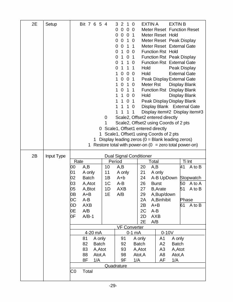
2E Setup Bit 7 6 5 4 3 2 1 0 EXTIN A EXTIN B0 0 0 0 Meter Reset Function Reset0 0 0 1 Meter Reset Hold0 0 1 0 Meter Reset Peak Display0 0 1 1 Meter Reset External Gate0 1 0 0 Function Rst Hold0 1 0 1 Function Rst Peak Display0 1 1 0 Function Rst External Gate0 1 1 1 Hold Peak Display1 0 0 0 Hold External Gate1 0 0 1 Peak DisplayExternal Gate1 0 1 0 Meter Rst Display Blank1 0 1 1 Function Rst Display Blank1 1 0 0 Hold Display Blank1 1 0 1 Peak DisplayDisplay Blank1 1 1 0 Display Blank External Gate1 1 1 1 Display item#2 Display item#3
0 Scale2, Offset2 entered directly1 Scale2, Offset2 using Coords of 2 pts
0 Scale1, Offset1 entered directly1 Scale1, Offset1 using Coords of 2 pts
1 Display leading zeros (0 = Blank leading zeros)1 Restore total with power-on (0 = zero total power-on)
2B Input Type Dual Signal Conditioner Rate Period Total Ti Int
00 A,B 10 A,B 20 A,B 41 A to B01 A only 11 A only 21 A only02 Batch 1B A+b 24 A-B UpDown Stopwatch03 A,Atot 1C A-B 26 Burst 50 A to A05 A,Btot 1D AXB 27 B,Arate 51 A to B0B A+B 1E A/B 29 A,Bup/down0C A-B 2A A,Binhibit Phase0D AXB 2B A+B 61 A to B0E A/B 2C A-B0F A/B-1 2D AXB
2E A/BVF Converter
4-20 mA 0-1 mA 0-10V81 A only 91 A only A1 A only82 Batch 92 Batch A2 Batch83 A,Atot 93 A,Atot A3 A,Atot88 Atot,A 98 Atot,A A8 Atot,A8F 1/A 9F 1/A AF 1/A
QuadratureC0 Total
-30-
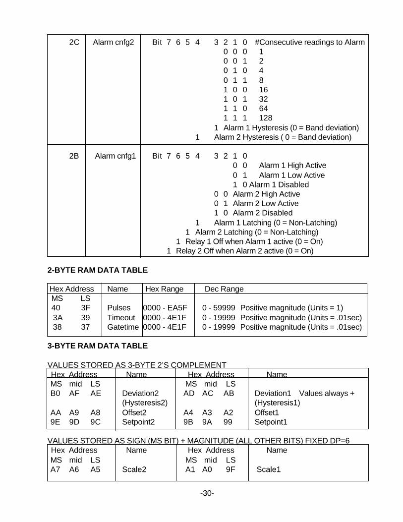
2C Alarm cnfg2 Bit 7 6 5 4 3 2 1 0 #Consecutive readings to Alarm0 0 0 10 0 1 20 1 0 40 1 1 81 0 0 161 0 1 321 1 0 641 1 1 128
1 Alarm 1 Hysteresis (0 = Band deviation)1 Alarm 2 Hysteresis ( 0 = Band deviation)
2B Alarm cnfg1 Bit 7 6 5 4 3 2 1 00 0 Alarm 1 High Active0 1 Alarm 1 Low Active1 0 Alarm 1 Disabled
0 0 Alarm 2 High Active0 1 Alarm 2 Low Active1 0 Alarm 2 Disabled
1 Alarm 1 Latching (0 = Non-Latching)1 Alarm 2 Latching (0 = Non-Latching)
1 Relay 1 Off when Alarm 1 active (0 = On)1 Relay 2 Off when Alarm 2 active (0 = On)
2-BYTE RAM DATA TABLE
Hex Address Name Hex Range Dec Range MS LS 40 3F Pulses 0000 - EA5F 0 - 59999 Positive magnitude (Units = 1)
3A 39 Timeout 0000 - 4E1F 0 - 19999 Positive magnitude (Units = .01sec)38 37 Gatetime 0000 - 4E1F 0 - 19999 Positive magnitude (Units = .01sec)
3-BYTE RAM DATA TABLE
VALUES STORED AS 3-BYTE 2’S COMPLEMENTHex Address Name Hex Address NameMS mid LS MS mid LSB0 AF AE Deviation2 AD AC AB Deviation1 Values always +
(Hysteresis2) (Hysteresis1)AA A9 A8 Offset2 A4 A3 A2 Offset19E 9D 9C Setpoint2 9B 9A 99 Setpoint1
VALUES STORED AS SIGN (MS BIT) + MAGNITUDE (ALL OTHER BITS) FIXED DP=6Hex Address Name Hex Address NameMS mid LS MS mid LSA7 A6 A5 Scale2 A1 A0 9F Scale1
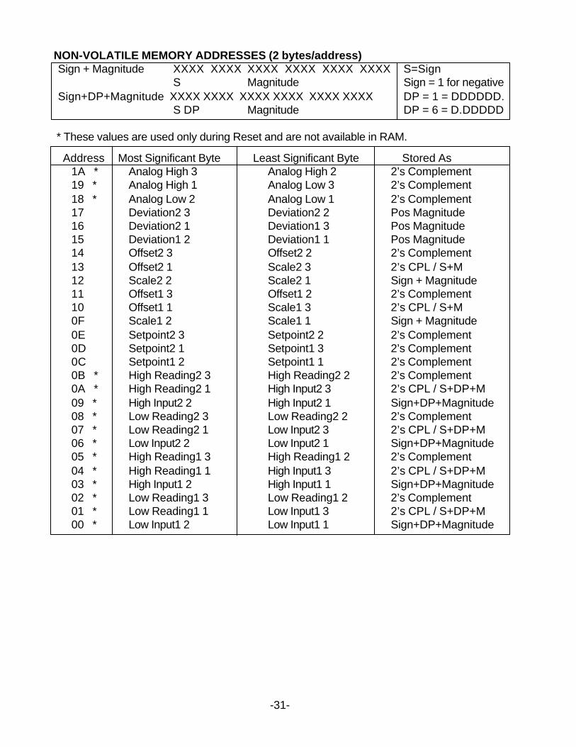
NON-VOLATILE MEMORY ADDRESSES (2 bytes/address)Sign + Magnitude XXXX XXXX XXXX XXXX XXXX XXXX S=Sign
S Magnitude Sign = 1 for negativeSign+DP+Magnitude XXXX XXXX XXXX XXXX XXXX XXXX DP = 1 = DDDDDD.
S DP Magnitude DP = 6 = D.DDDDD
* These values are used only during Reset and are not available in RAM.
Address Most Significant Byte Least Significant Byte Stored As1A * Analog High 3 Analog High 2 2’s Complement19 * Analog High 1 Analog Low 3 2’s Complement18 * Analog Low 2 Analog Low 1 2’s Complement17 Deviation2 3 Deviation2 2 Pos Magnitude16 Deviation2 1 Deviation1 3 Pos Magnitude15 Deviation1 2 Deviation1 1 Pos Magnitude14 Offset2 3 Offset2 2 2’s Complement13 Offset2 1 Scale2 3 2’s CPL / S+M12 Scale2 2 Scale2 1 Sign + Magnitude11 Offset1 3 Offset1 2 2’s Complement10 Offset1 1 Scale1 3 2’s CPL / S+M0F Scale1 2 Scale1 1 Sign + Magnitude0E Setpoint2 3 Setpoint2 2 2’s Complement0D Setpoint2 1 Setpoint1 3 2’s Complement0C Setpoint1 2 Setpoint1 1 2’s Complement0B * High Reading2 3 High Reading2 2 2’s Complement0A * High Reading2 1 High Input2 3 2’s CPL / S+DP+M09 * High Input2 2 High Input2 1 Sign+DP+Magnitude08 * Low Reading2 3 Low Reading2 2 2’s Complement07 * Low Reading2 1 Low Input2 3 2’s CPL / S+DP+M06 * Low Input2 2 Low Input2 1 Sign+DP+Magnitude05 * High Reading1 3 High Reading1 2 2’s Complement04 * High Reading1 1 High Input1 3 2’s CPL / S+DP+M03 * High Input1 2 High Input1 1 Sign+DP+Magnitude02 * Low Reading1 3 Low Reading1 2 2’s Complement01 * Low Reading1 1 Low Input1 3 2’s CPL / S+DP+M00 * Low Input1 2 Low Input1 1 Sign+DP+Magnitude
-31-
6.3 WEIGHT METER1-BYTE RAM DATA TABLE
Hex Hex Address Item Name Value
6B Configuration Bit 7 6 5 4 3 2 1 00 = Linear Data1 =Custom Curve (Extended DPM)
0 = Peak of net value1 = Peak of gross value
0 = Setpoint off set enabled1 = Setpoint offset disabled
0 = Setup scale method1 = Reading 2 coord method
0 0 0 = Not Rate0 0 1 = Rate X 0.10 1 0 = Rate X 10 1 1 = Rate X 101 0 0 = Rate X 1001 0 1 = Rate X 10001 1 0 = Rate X 10,000
0 = Not used
BF Analog Setup Bit 7 6 5 4 3 2 1 0 bit0 = Analog Out Unfiltered1 = Analog Out Filtered
0 = Current Output1 = Voltage Output
0 = Output of net value1 = Output of gross value
0 0 0 0 0 = Not used
35 Decimal point 01 Byte values in hex XXXXX.02 (2 hex characters/byte) XXXX.X03 XXX.XX04 XX.XXX05 X.XXXX06 .XXXXX
34 Lockout2 Bit 7 6 5 4 3 2 1 0 bit = 0 is unlocked for all items1 = SEr 1, Ser 2, Ser3 locked
1 = An Lo, An Hi locked1 = Alarm setpoint programming locked
1 = ALSEt locked1 = Front panel DPM Reset locked
1 = Front panel Peak & Alarm Reset locked1 = View Alarm setpoints locked
1 = View Peak value locked-32-
-33-
33 Lockout1 Bit 7 6 5 4 3 2 1 0 bit = 0 is unlocked for all items1 = Count locked
1 = Setup, config and dEC.Pt locked1 = Input type locked
1 = Change display item number1 = Tare Locked
1 = Offset, LO, HI RD locked1 = View alarm setpoints locked
1 = View peak locked
32 Serial Cnfg2 Bit 7 6 5 4 3 2 1 0X X X X X = DPM address 0-31 (5 bits)
1 = Command mode (0 = Continuous mode)1 = Alarm data included with reading (0=excluded)
1 = LF following CR (0= no LF)
31 Serial Cnfg1 Bit 7 6 5 4 3 2 1 0 Continuous Output Data Rate60 Hz 50 Hz
0 0 0 0 .017s 02s0 0 0 1 .28 .340 0 1 0 .57 .680 0 1 1 1.1 1.40 1 0 0 2.3 2.70 1 0 1 4.5 5.40 1 1 0 9.1 10.90 1 1 1 18.1 21.81 0 0 0 36.3 43.51 0 0 1 72.3 86.7
0 0 0 300 baud0 0 1 600 baud0 1 0 1200 baud0 1 1 2400 baud1 0 0 4800 baud1 0 1 9600 baud1 1 0 19200 baud
1 = Send filtered value (0= send unfiltered value)
17 Serial Cnfg3 Bit 7 6 5 4 3 2 1 0 Data Sent0 0 0 .Net and gross0 0 1 Net only0 1 0 Gross only0 1 1 Peak only1 0 0 Net, gross and peak
0 CR (LF) after all items (1=after each item)0 Non-latching RTS (1 = Latching RTS)
0 Not used0 RS 485 full duplex (1 = Half duplex)
2F Filter Bit 7 6 5 4 3 2 1 00 0 0 0 Auto Filter0 0 0 1 Batch (16 samples) filter
Time constant 60 Hz 50 Hz0 0 1 0 Moving Average .07s .085s0 0 1 1 Moving Average .14 .170 1 0 0 Moving Average .28 .340 1 0 1 Moving Average .57 .680 1 1 0 Moving Average 1.13 1.360 1 1 1 Moving Average 2.27 2.721 0 0 0 Moving Average 4.53 5.441 0 0 1 Moving Average 9.06 10.881 0 1 0 Unfiltered
1 = High adaptive threshold (0 = low threshold)1 = Display filtered signa l (0 = display batch)
1 = Take peak of filtered signal (0 = unfiltered)1 = Alarm from filtered signal (0 = unfiltered)
2E Setup Bit 7 6 5 4 3 2 1 0 EXT IN A EXT IN B0 0 0 0 Meter Reset Meter Hold0 0 0 1 Function Reset Peak Display0 0 1 0 Meter Hold Peak Display0 0 1 1 Meter Hold Tare0 1 0 0 Peak Display Tare0 1 0 1 Meter reset Tare0 1 1 0 Function reset Tare0 1 1 1 Tare reset Tare1 0 0 0 Display blank Tare1 0 0 1 Meter reset Display blank1 0 1 0 Function Reset Display blank1 0 1 1 Display item Tare1 1 0 0 Display item Display blank1 1 0 1 Meter reset Display item1 1 1 0 Function reset Display item1 1 1 1 Meter hold Display item
0 Scale using scale and offset1 Scale using coordinates of two points
0 Peak key displays peak1 Peak key tares net value
0 No dummy zero1 Displays dummy zero
-34-
3-BYTE RAM MEMORY DATA
All items except Scale Factor use this format:Note: Hex value (2's complement) MS byte Mid byte LS byte
X X X X X X Scale factor uses this format: MS byte Mid byte LS byteMS Bit ( 0 = Polarity and Decimal Point) 0 X X X X X Positive 1 Negative 9 Decimal point XXXXX.
2 A Decimal point XXXX.X3 B Decimal point XXX.XX4 C Decimal point XX.XXX5 D Decimal point X.XXXX
Note: Hex value (Absolute value) 6 E Decimal point .XXXXX
2C Alarm Cnfg2 Bit 7 6 5 4 3 2 1 0 Alarm Trigger Delay60 Hz 50Hz
0 0 0 .018s .021s0 0 1 .035 .0430 1 0 .07 .0850 1 1 .14 .171 0 0 .28 .341 0 1 .56 .681 1 0 1.13 1.361 1 1 2.27 2.72
Alarm comparison0 0 0 0 0 AL1 Net, AL2 Net0 0 0 0 1 AL1 Gross, AL2 Net0 0 0 1 0 AL1 Net, AL2 Gross0 0 0 1 1 AL1 Gross, AL2 Gross
2B Alarm Cnfg1 Bit 7 6 5 4 3 2 1 00 0 0 0 AL1 hi activ, AL2 hi activ0 0 0 1 AL1 lo activ, AL2 hi activ0 0 1 0 AL1 disabled, AL2 hi activ0 1 0 0 AL1 hi activ, AL2 lo activ0 1 0 1 AL1 lo activ, AL2 lo activ0 1 1 0 AL1 disabled, AL2 lo activ1 0 0 0 AL1 hi activ, AL2 disabled1 0 0 1 AL1 lo activ, AL2 disabled1 0 1 0 AL1 disabled, AL2 disabled
0 0 AL1 non-latch, AL2 non-latch0 1 AL1 latch, AL2 non-latch1 0 AL1 non-latch, AL2 latch1 1 AL1 latch, AL2 latch
0 0 Relay 1 ON, Relay 2 ON0 1 Relay 1 OFF, Relay 2 ON1 0 Relay 1 ON, Relay 2 OFF1 1 Relay 1 OFF, Relay 2 OFF
-35-
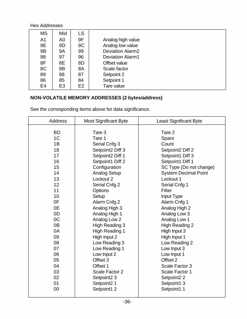
Hex Addresses
MS Mid LSA1 A0 9F Analog high value9E 9D 9C Analog low value9B 9A 99 Deviation Alarm298 97 96 Deviation Alarm18F 8E 8D Offset value8C 8B 8A Scale factor89 88 87 Setpoint 286 85 84 Setpoint 1E4 E3 E2 Tare value
NON-VOLATILE MEMORY ADDRESSES (2 bytes/address)
See the corresponding items above for data significance.
Address Most Significant Byte Least Significant Byte
BD Tare 3 Tare 21C Tare 1 Spare1B Serial Cnfg 3 Count18 Setpoint2 Diff 3 Setpoint2 Diff 217 Setpoint2 Diff 1 Setpoint1 Diff 316 Setpoint1 Diff 2 Setpoint1 Diff 115 Configuration SC Type (Do not change)14 Analog Setup System Decimal Point13 Lockout 2 Lockout 112 Serial Cnfg 2 Serial Cnfg 111 Options Filter10 Setup Input Type0F Alarm Cnfg 2 Alarm Cnfg 10E Analog High 3 Analog High 20D Analog High 1 Analog Low 30C Analog Low 2 Analog Low 10B High Reading 3 High Reading 20A High Reading 1 High Input 309 High Input 2 High Input 108 Low Reading 3 Low Reading 207 Low Reading 1 Low Input 306 Low Input 2 Low Input 105 Offset 3 Offset 204 Offset 1 Scale Factor 303 Scale Factor 2 Scale Factor 102 Setpoint2 3 Setpoint2 201 Setpoint2 1 Setpoint1 300 Setpoint1 2 Setpoint1 1
-36-
-38 -
7.0 SOURCE LISTING
B & B Electronics Manufacturing Co.707 Dayton RoadOttawa, IL 61350
Phone: (815) 433-5100Fax: (815) 433-5109Website: www.bb-elec.com
B & B manufactures a variety RS485 to RS232 converters and RS232 and RS485 to USBconverters. They also have RJ11 to 9 pin adapters .
The Model 485OT9L is the recommended RS485 to RS232 converter.

WARRANTY
Laurel Electronics Inc. warrants its products against defects in materials or workmanship for aperiod of one year from the date of purchase.
In the event of a defect during the warranty period, the unit should be returned, freight prepaid (andall duties and taxes) by the Buyer, to the authorized Laurel distributor where the unit was purchased.The distributor, at its option, will repair or replace the defective unit. The unit will be returned to thebuyer with freight charges prepaid by the distributor.
LIMITATION OF WARRANTYThe foregoing warranty shall not apply to defects resulting from:
1. Improper or inadequate maintenance by Buyer.2. Unauthorized modification or misuse.3. Operation outside the environmental specifications of the product.4. Mishandling or abuse.
The warranty set forth above is exclusive and no other warranty, whether written or oral, isexpressed or implied. Laurel specifically disclaims the implied warranties of merchantability andfitness for a particular purpose.
EXCLUSIVE REMEDIESThe remedies provided herein are Buyer’s sole and exclusive remedies. In no event shall Laurelbe liable for direct, indirect, incidental or consequential damages (including loss of profits) whetherbased on contract, tort, or any other legal theory.

Copyright 1996-2004 Laurel Electronics Inc. 06/04 Rev. E