Embed Size (px)
Citation preview
M I N I S T R Y OF A V I A T I O N
A E R O N A U T I C A L RESEARCH C O U N C I L
REPORTS AND MEMORANDA
R. & M. No. 3334
The Lateral Motion of Aircraft, and in particular o f Inertially Slender Configurations
By W. J. G. PINSKER
L O N D O N : ~ H E R MAJESTY'S S T A T I O N E R Y OFFICE
1963
PRICE £ I 55, od. NET
The Lateral Motion of Aircraft, and in particular of Inertially Slender Configurations
By W. J. G. PINSKER
COMMUNICATED BY THE DEPUTY CONTROLLER AIRCRAFT (RESEARCH AND DEVELOPMENT),
MINISTRY OF AVIATION
Reports and Memoranda No. 3334* S@tember, z96±
Summary.
The kinematic and dynamic characteristics of the lateral motion of aircraft are described and reduced to simple models. After a review of the typical lateral modes of traditional aircraft configurations it is shown that with modern low-aspect-ratio designs at higher incidences the lateral oscillation tends to degenerate into a simple roiling oscillation about the principal inertia axis, whereas the roll subsidence is increasingly dominated by yawing moments. The consequences of these phenomena from the point of view of the stability and control of such aircraft; described as inertially slender, are discussed in detail and approximate formulae are given, which permit the early assessment of the general trends in the stability and response characteristics of this class of aircraft.
Section
1.
2.
3.
.
L I S T OF C O N T E N T S
Introduction
The Equations of Motion
The Kinematics of the Lateral Motion of Aircraft
3:1 Spiral motion
3.2 Roll subsidence
3.3 The lateral oscillation
The Principal Types of Lateral Oscillation
4.1 Directional oscillation
4.2 Directional oscillation with freedom in lateral movement
4.3 The 'Lanchester ' oscillation
4~4 Conventional dutch roll
4.4.1 Aircraft with large damping in roll when compared with inertia in roll
4.4.2 Aircraft with inertia in roll large when compared with damping in roll
e Replaces R.A.E. Report No. Aero. 2656--A.R.C. 23,434.

Section
LIST OF CONTENTS--continued
4.5 Pure rolling oscillation
4.6 Rolling oscillation with lateral freedom
5. Applicability of the Concept of the Inertially Slender Configuration
6. The Principal Features of the Inertially Slender Aircraft
6.1 The lateral oscillation
6.2 Aircraft response to lateral control
6.3 Response to lateral gusts
6.4 Automatic stabilisation
6.5 Wind-tunnel testing
7. Conclusions
List of Symbols
List of References
Appendices I to IV
Tables la to 4
Illustrations--Figs. 1 to 35
Detachable Abstract Cards
LIST OF APPENDICES Appendix
I. Transformation of lateral-stability derivatives from stability axes to body axes
and vice versa
II. Transformation of dutch-roll ratio from body axes to wind axes
III. Aileron response of the inertially slender aircraft
IV. Rudder response of the inertially slender aircraft
LIST OF TABLES Table
la. The coefficients of the stability quartic and the stability determinants for the lateral motion of the aircraft in stability axes and in principal inertia axes for level
flight
lb. Definitions of concise derivatives used in the stability equations of Table la
2. Approximate formulae for the stability parameters of various simplified types of
lateral oscillations
3. Geometric, inertia and aerodynamic data used for the aircraft as an example in
the roll-response calculations
4. Approximate formulae for the roll-response parameters of the conventional and of
the inertially slender aircraft
2

Figure 1.
o
3.
4.
5.
6.
7.
8.
.
10.
11.
12.
13.
14.
15.
16.
17.
18.
19.
20.
21.
22.
23.
24.
25.
26.
LIST OF ILLUSTRATIONS
Definition of the stability axes system and the body (principal inertia axes) system in the aircraft
Moments and rates of rotation in stability axes and body axes
Spiral motion of the aircraft in plan view
Rolling about the stability axis
Rolling aboutthe body axis
Roll-subsidence motion of the aircraft
Time history of a typical lateral oscillation and definition of dutch-roll ratio
Change of dutch-roll ratio p/r with incidence of reference system with respect to stability axes
Change of the ratio of fp dt/fl with incidence of reference system for p
Pure directional oscillation
Yawing oscillation with freedom in lateral movement
'Lanchester' oscillation
Conventional dutch roll (large aspect ratio)
Dutch roll of more advanced aircraft (small aspect ratio)
Pure rolling about body axis
n v and l v referred to stability axes and body axes for two delta-aircraft configurations
Yawing moment due to rate of roll np in stability axes and body axes for two delta aircraft
Inertia distributions of typical fighter aircraft
Rolling oscillation about body axis with lateral movement
Comparison of the stability parameters of the lateral oscillation of a swept-wing aircraft with the approximations based on the classical dutch-roll concept and the rolling mode respectively
Comparison of the stability parameters of the lateral oscillation of a delta-wing aircraft with the approximations based on the classical dutch-roll concept and the rolling mode respectively
Comparison of the stability parameters of the lateral oscillation of a slender-wing aircraft with the approximations based on the classical dutch-roll concept and the rolling mode respectively
The regimes of validity for the two basic models of lateral oscillations
Effects of changes in aerodynamic derivatives on the stability of the lateral oscillation
Effects of changes in aircraft loading on the stability of the lateral oscillation
Response in roll of three basic aircraft configurations to sudden aileron application
3 ( 8 7 5 4 1 ) A 2
Figure
27.
28.
2%.
29b.
"30.
31.
32.
33.
34.
35.
LIST OF ILLUSTRATIONS--cont inued
Response in roll of an inertially slender aircraft to various amounts of aileron applied
instantaneously at t = 0
Response of a practical inertially slender aircraft to an aileron step input
Initial bank angle in response to aileron for aircraft defined in Table 3
Final steady rate of roll Po~ in response to aileron for inertially slender aircraft
defined in Table 3
Time constant t~j for the roll-subsidence mode of the inertially slender aircraft
defined in Table 3
Steady rolling response of an incrtially slender aircraft to aileron, rudder, or to
both controls geared ~/~ = 1.0
Coupled lateral control layout for improved roll response of inertially slender aircraft
Incremental incidence As required for turn co-ordination after the completion
of a pure bank manoeuvre
Equilibrium bank angle in response to a side-gust vg of an inertially slender aircraft
Approximate response in bank of the aircraft defined in Table 3 to a 20 ft/sec
sharp-edged side-gust
1. Introduction.
The classical approach to aircraft stability and control analysis has largely evolved round the
concept of the aircraft as an aerodynamic system, a system, that is, the behaviour of which is predominantly determined by its aerodynamic properties. This concept has to a large extent influenced such formal choices as the definition of the preferred system of axes and of the stability
derivatives. The system of stability axes has indeed served us well in all aspects of aircraft stability work, in particular as it permits the partial aerodynamic derivatives to be isolated with ease in
experimental techniques. However, with the increase in wing loading and the trend to a more elongated inertia distribution,
gyroscopic forces and moments are exerting an increasing influence on the dynamic behaviour of the modern aircraft. The phenomenon usually referred to as inertia cross coupling 1,2,'~ is a dramatic example of such effects on the stability of aircraft in fast roiling manoeuvres. Two conclusions from the analytical work done on inertia cross coupling may be noted as being potentially significant for
aircraft stability analysis in general:
(i) Analysis of the dynamics of aircraft with relatively large inertias is simplified by using principal inertia axes rather than stability axes as the reference system.
(ii) The inertia distribution becomes a dominating factor in determining the airc)aft stabifity.
Further, it has been demonstrated that treatment of the lateral and longitudinal motion of aircraft
as essentially separate problems is no longer permissible in some cases.
4

At the same time more recent work on the lateral stability of modern aircraft 1° has clearly shown the importance of gyroscopic moments normally referred to as product of inertia terms, and it has
i'n consequence become increasingly difficult to reduce the analysis to a physically clear picture of the kinematics and dynamics governing the lateral motions of the more advanced swept-wing
aircraft. Akhough at low incidence most aircraft show a lateral behaviour consistent with the classical modes of motion (dutch roll, roll subsidence and spiral mode) at higher incidence these modes appear to develop into highly complex coupled motions, the understanding of which is often obscured by a host of cross-coupling terms both of aerodynamic and inertial origin. It is of course Obvious that the results of mathematical analysis are invariant to the choice of the reference system --as long as it is consistent--and it would appear that no advantage can be gained by departing with such analysis from the conventional system of stability axes with its obvious ease of defining the aerodynamic derivatives. However, it is not equally true to say that the interpretation of the reStalt of such analysis is not facilitated by the choice of another reference system. For example, it has been observed for some time that the dutch-roll oscillation of swept-wing aircraft changes gradually, as incidence is increased, from first an almost pure directional oscillation to a typical
dutch roll and finally to an oscillation which appears to be practically pure rolling about this fuselage axis. It has also become apparent that this trend is more pronounced with aircraft having a very
'slender' inertia distribution, i.e. aircraft in which most of the weight is distributed along a long
fuselage. It is shown in. the present paper that the 'rolling oscillation' typical of this type of configuration
can be more readily understood if analysis is conducted in principal inertia axes and that for
sufficiently extreme cases very useful numerical approximations can then be obtained for all the
principal stability and control parameters b y very crude simplifications of the analysis° The paper begins with a review of the more conventional forms of lateral motions and leads on
to a broad discussion of the principal physical phenomena governing these modes of motion by reducing them to simple kinematic models. Finally a simple criterion is derived determining for a given configuration the flight conditions at which its lateral behaviour is likely to be dominated by the one or the other of the types of motion considered.
The numerical results given by the relatively crude procedure suggested in the present paper are of course applicable only for configurations Which are sufficiently extreme in their relevant chaff/cteristics to satisfy the assumptions made in deriving the simple modes of motion considered. Nevertheless the formulae given are useful both in demonstrating trends and also in establishing the general level of the stability and control parameters for a given aircraft. It is suggested that the approach outlined here should be most useful in preliminary work on the stability and control features of a new design and in general in studies where physical understanding and a broad grasp of the problem are more important than exact numerical computations. The latter will in any case only be possible when all the relevant aerodynamic data and the inertia characteristics of the aircraft are known with sufficient certainty. When they are known, better approximations such as those given in ReL 10 are more appropriate. They can be shown to predict the characteristics of the dutch-roll oscillation even of the most extreme cases considered here with excellent accuracy.
2. The Equations of Motion.
As the use of either system of axes is considered here the equations of motion are given both with
reference to stability axes and to principal inertia axes. In keeping with usual practice in linear theory,
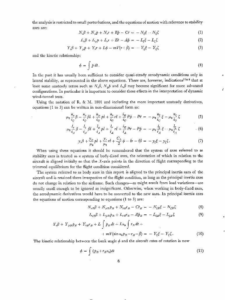
the analysis is restricted to small perturbations, and the equations of motion with reference to stability axes are:
N 3 + N,)p + Nrr + E~ - C~ = - N d - N d (1)
L~/3 + Lpp + Lrr + Ei" - A !3 = - L ~ - L ~ (2)
Y~/3 + Y~,p + Yrr + L ¢ - m V ( r +l~ ) = - Y ~ - Y ~ (3)
and the kinetic relationship:
¢ = f 20 dr. (4)
In the past it has usually been sufficient to consider quasi-steady aerodynamic conditions only in lateral stability, as represented in the above equations. There are, however, indications 7 to 9 that at
least some unsteady terms such as N~fi, Ni)p and L~fl may become significant for more advanced configurations. In particular it is important to consider these effects in the interpretation of dynamic wind-tunnel tests.
Using the notation of R. & M. 1801 and including the more important unsteady derivatives, equations (1 to 3) can be written in non-dimensional form as:
~ ~_~fi~+~. ^ ~,. , i~ n~ n ~ (5)
l~ /~ I v ^ l, iE 1¢ ~ _ . 2 l ~ ¢ . (6)
- - C L h" ~fi -- yg~ -- y ~ ¢ . (7) y f i + Y v p ~ + Y " r ~ + _ ~ _ ¢ _ - = tz2 fz~.
When using these equations it should be remembered that the system of axes referred to as stability axes is treated as a system of body-fixed axes, the orientation of which in relation to the aircraft is aligned initially so that the X-axis points in the direction of flight corresponding to the trimmed equilibrium for the flight condition considered.
The system referred to as body axes in this report is aligned to the principal inertia axes o'f the aircraft and is retained there irrespective of the flight condition, as long as the principal inertia axes do not change in relation to the airframe. Such changes--as might result from load variations--are usually small enough to be ignored as insignificant. Otherwise, when working in body-fixed axes, the aerodynamic derivatives would have to be converted to the new axes. In principal inertia axes the equations of motion corresponding to equations (1 to 3) are:
N,B/3 + N ± ~ p B + NrBrB -- Ci" B = - NgB~ -- N;B~ (8)
LvB/3 + LpBPB + LrBr2~ -- A2b~ = - LgB ~ -- LgB~ (9)
Y~/3 + ¥~Pz, + Y~r~ + L f P~dt + L% f r~dt +
+ m V ( s i n % p B - - r z - - f i ) = - Y ~ $ - Y~[ . (10)
The kinetic relationship between the bank angle ¢ and the aircraft rates of rotation is now
0 = f (PB + rB%)dt (11)

where a 0 is the incidence of the principal inertia axis and suffix B (body) denotes principal inertia axes. The relationship equation (11) introduces two terms into the side-force equation to replace the gravity term (L¢) in equation (3). Also this equation contains the kinematic term (PB sin %) which physically expresses the effect of the product-of-inertia terms now omitted from the moment equations. It should be noted that as both the stability axes system and the principal axes system have a common Y-axis, equations (3) and (10) are strictly equivalent.
In non-dimensional form equations (8 to 10) can be written, again introducing the principal unsteady terms:
nvB~ '~eB fif n:~B n~B ~ . ,~ ngB ~ _ lz2nf B ~ (12) /z2 ~ P + zc° + ~ PB~ + zc o=- rBt - rBt = _ 1~2 ic o zoo
t~ ~ fi + fit + : - - p B t + = - r~ t - p ~ t = - t~ = - ~ - m ~ - ¢ i~o ~ '~o ~o ~,o ~o
(13)
yv]3 + (1 - YrB]fz~ / rB ~ + \(YrBtZS + sin a o) Pz~ +
f f = _yg~_y~. +--2- pBdt + 2 - (14)
Three of the aerodynamic derivatives, namely the side-force derivatives Yv, Y~ and y~ are identical in both systems. The remaining derivatives can be transformed using the expression given in Appendix I.
As the two alternative sets of equations describe an identical physical system, they both result in the same stability quartic as a solution.
~4 + 4h~ + 4 h . + J l h + J0 = 0. (15)
Comparison between the akernative expressions given in Table 1 shows that the expression for the coefficients in principal inertia axes are generally simpler, the exception being the absolute term, which is algebraically much less complex in the stability axis system. Using this consideration as the only criterion k would appear that stability analysis may benefit by a change of ks reference system to principal inertia axes. However, as aerodynamic data are usually given in stability axes the labour in first transforming these into the new system would far outweigh the savings in the computation of the stability coefficients. The reverse is of course true if the aerodynamic derivatives are originally given in body axes, such as are used frequently in high-speed tunnels when sting- mounted models are tested. It must be remembered, however, that the 'body axes' of the sting balance do not necessarily coincide with the principal inertia axis of the aircraft and derivative transformation may still be required.
It is obvious that considerations of such a formal nature are hardly a sufficiently reliable guide to a sound choice of a preferred reference system.
In the following sections of this report it will be shown that at least certain more extreme aircraft configurations possess a unique 'natural' reference system for their lateral motion, which facilitates both crude numerical estimations and, in particular, better physical insight.
Finally, it should again be pointed out that there is, however, no advantage in any particular system so far as more formal mathematical analysis is concerned.
7
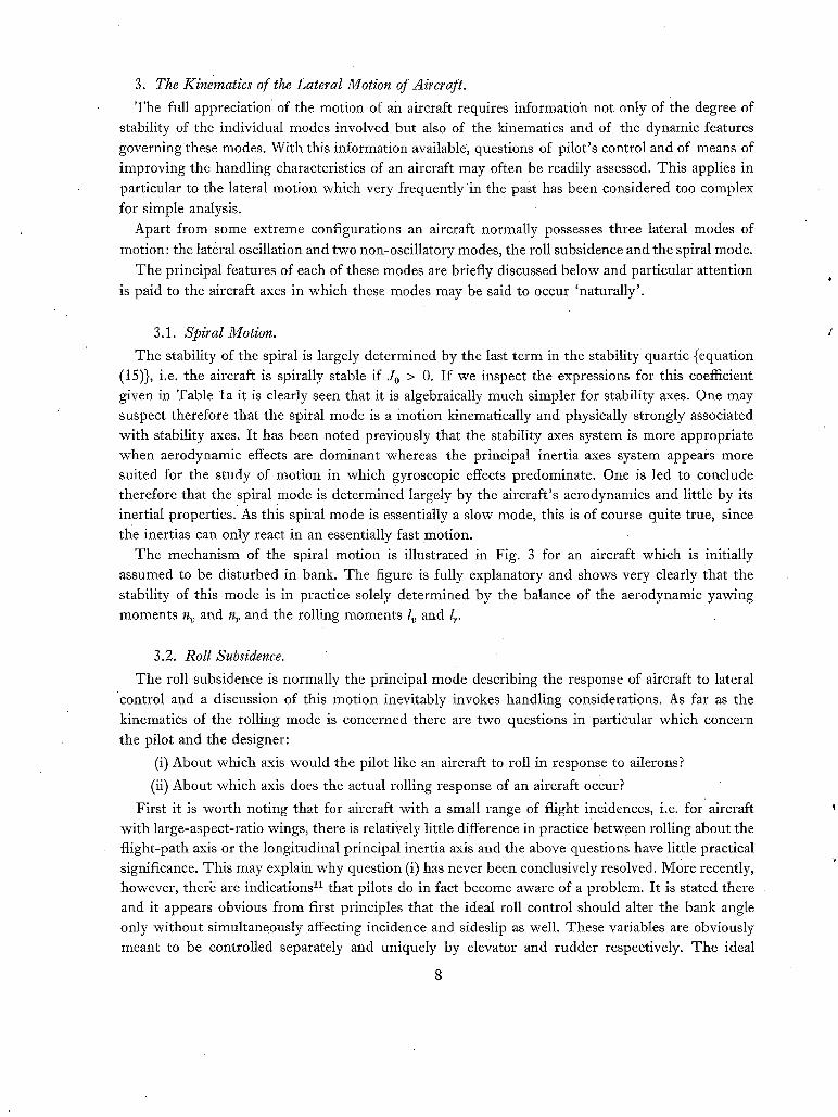
3. The Kinematics of the Lateral Motion of Aircraft.
The full appreciation of the motion of an aircraft requires information not only of the degree of stability of the individual modes involved but also of the kinematics and of the dynamic features governing these modes. With this information available', questions of pilot's control and of means of improving the handling characteristics of an aircraft may often be readily assessed. This applies in particular to the lateral motion which very frequently'in the past has been considered too complex
for simple analysis.
Apart from some extreme configurations an aircraft normally possesses three lateral modes of
motion: the lateral oscillation and two non-oscillatory modes, the roll subsidence and the spiral mode.
The principal features of each of these modes are briefly discussed below and particular attention
is paid to the aircraft axes in which these modes may be said to occur 'naturally'.
3.1. Spiral Motion.
The stability of the spiral is largely determined by the last term in the stability quartic {equation (15)}, i.e. the aircraft is spirally stable if J0 > 0. If we inspect the expressions for this coefficient given in Table la it is clearly seen that it is algebraically much simpler for stability axes. One may suspect therefore that the spiral mode is a motion kinematically and physically strongly associated with stability axes. It has been noted previously that the stability axes system is more appropriate when aerodynamic effects are dominant whereas the principal inertia axes system appears more suited for the study of motion in which gyroscopic effects predominate. One is led to conclude therefore that the spiral mode is determined largely by the aircraft's aerodynamics and little by its inertial properties. As this spiral mode is essentially a slow mode, this is of course quite true, since tl~e inertias can only react in an essentially fast motion.
The mechanism of the spiral motion is illustrated in Fig. 3 for an aircraft which is initially assumed to be disturbed in bank. The figure is fully explanatory and shows very clearly that the stability of this mode is in practice solely determined by the balance of the aerodynamic yawing moments n v and n~ and the rolling moments lv and l~.
3.2. Roll Subsidence.
The roll subsidence is normally the principal mode describing the response of aircraft to lateral control and a discussion of this motion inevitably invokes handling considerations. As far as the
kinematics of the rolling mode is concerned there are two questions in particular which concern the pilot and the designer:
(i) About which axis would the pilot like an aircraft to roll in response to ailerons?
(ii) About which axis does the actual rolling response of an aircraft occur?
First it is worth noting that for aircraft with a small range of flight incidences, i.e. for ~ aircraft with large-aspect-ratio wings, there is relatively little difference in practicebetween rolling about the flight-path axis or the longitudinal principal inertia axis and the above questions have little practical significance. This may explain why question (i) has never been conclusively resolved. More recently, however, there are indications 11 that pilots do in fact become aware of a problem. It is stated there and it appears obvious from first principles that the ideal roll control should alter the bank angle only without simultaneously affecting incidence and sideslip as well. These variables are obviously meant to be controlled separately and uniquely by elevator and rudder respectively. The ideal

rolling manoeuvre thus defined implies rotation about the flight-path axis, i.e. about the X-axis of the stability axes system as illustrated in Fig. 4. Rolling about a body axis initially at an incidence
~0 would result kinematically in changes in incidence and sideslip as can be seen in Fig. 5. .. The actual rolling motion of a given aircraft depends on the inertia and aerodynamic features of
the design. As a most general statement one may say that in rolling, the aircraft follows the path of least resistance. With more conventional configurations having modest inertias and relatively strong
aerodynamic (weathercocking) restraints, the aircraft tends to roll about the flight-path axis, so as
to retain aerodynamic trim (in general fi = 0 and ~ = s0) during the motion. On the other hand on a highly loaded modern aircraft, inertias are likely to offer the more powerful resistance and the
rolling motion must be expected to be more nearly about the minimum inertia axis, i.e. a body axis
roughly aligned with the fuselage. Rolling about the flight-path axis involves only damping in roll and inertia in roll as the aircraft's
reactions. This corresponds obviously to a simple first-order system, the response of which is
described normally by a convergent mode, the familiar roll subsidence. As in practice, a certain
amount of aerodynamic coupling inevitably involves yawing as well, the roll-subsidence motion is a
form of barrel roll. An attempt has been made to illustrate this mode in Fig. 6 for two cases with np > 0 and n2~ < 0 respectively. For pictorial clarity thediameter of the 'barrel' has been exaggerated.
The resulting motion is again a motion about a flight-path axis, which, if gravity is ignored, is a
straight line. In Ref. 6 the time constant of this mode has been given approximately as: \ •
1 / J tjo g - 1 3 - 0 5 W/S (.~ ixi o (16)
1 zv
A more accurate approximation is given in Ref. 10. It is seen from Fig. 5 that rolling about the principal inertia axis (if ~0 4 = 0) generates periodic
changes of incidence and sideslip and as a consequence it cannot possibly describe an aperiodic mode, which by definition the roll subsidence must be. Thus the only physically possible roll subsidence must be of the type illustrated in Fig. 6. This does, however, not necessarily imply that
the response of an aircraft in roll (say to aileron or to gusts) is always predominantly described by the roll subsidence. With more conventional configurations, and in particular if there is a large-
aspect-ratio wing providing substantial damping in roll, and if the aircraft inertias are not too
extreme , this will, however, generally be the case. On the other hand for small-aspect-ratio wings with relatively large inertias the time c0nstant:
{equation (16)} of the roll-subsidence mode may be so long (in relation to the period of the lateral
oscillations) that at least the immediate response of the aircraft to lateral control is determined "more
by the dutch-roll mode. It is very important to be fully aware of this phenomenon, as then the conventional criteria for the assessment of lateral control, being based on the concept of the roll-
subsidence motion, may give very misleading results. If the aircraft has large inertias and a distinctly slender inertia distribution (A ~ C), rolling about
the principal inertia axis becomes the dominating feature of the lateral oscillation. This phenomenon
is discussed (in Section 6) later in this report where the relative significance of the roll subsidence and the lateral oscillation in the response of an aircraft to lateral control and gusts is studied in
more detail. r

3.3. The Lateral Oscillation.
The lateral oscillation or dutch roll, as it is frequently called, is perhaps the most difficult of the
lateral modes to reduce to a simple model. Apart from some extreme configurations--when compared with the typical present-day design--the dutch roll appears to be generally a motion in which all
three lateral freedoms are strongly intercoupled. I t is usually defined by the three parameters, period, damping, and the dutch-roll ratio, i.e. the ratio between the amplitudes in roll and in yaw
as illustrated in Fig. 7.
Whereas period and damping can be uniquely defined, it is generally realised that the numerical
value for the dutch-roll ratio is frequently very sensitive to the choice of axes to which p and r are referred. In Fig. 8 this is illustrated for a hypothetical case in which the dutch-roll ratio (when
expressed in stability axes) is assumed to have the value p/r = 2.5, and rate of roll is considered to
lag behind rate of yaw by two values, 160 ° and 170 ° phase angle respectively. (It can be shown that this range is typical for the modern small-aspect-ratio aircraft.) The corresponding values of p/r when referred to a system of body axes at an incidence ~ with respect to the stability axes sys tem are seen to increase with incidence until a maximum is reached at a certain value of ~, beyond
which p/r falls again. The method of axes transformation employed is based on the time-vector
concept and is described in Appendix I I and illustrated graphically at the top of Fig. 8. There it is
seen that although the value of p changes very little in transforming it to body axes, r diminishes
rapidly with increasing incidence. I t is obvious that rate of yaw would vanish altogether
(i.e. p/r ~ oo) at a certain incidence if the phase lag between p and r is 180°. This phase angle,
e2)_+r, for a lateral oscillation with the frequency ~o 0 rad/sec, is given approximately by:
e ~ r = - 7r - tan -1 \ia~°ot]
For aircraft with low damping in roll ( - l~j) and relatively large inertia in roll this angle approaches
- 180 °. Both these conditions apply to the modern low-aspect-ratio design. I t is obvious that to the pilot the lateral oscillation of this type of aircraft appears as a pure rolling oscillation. I t will be shown later in this report that this description of the lateral oscillation does in fact indicate a condition in which the lateral motion of an aircraft can be reduced to a very simple model restricted to rolling about the principal inertia axis only.
In order to avoid any ambiguity in the definition of the dutch-roll ratio it is advisable to try to find an alternative definition which is less sensitive to the choiceof axes. Such a definition has been used in recent American work and is the ratio between bank angle ~b and sideslip/~. Fig. 9 shows
that even if for convenience in the calculation ~p dt is used instead of the true bank angle, ~, this ratio is hardly affected by the choice of the reference system. Naturally this is true only if ~p dt > ~, but the dutch-roll ratio is only a significant parameter if it is large anyway.
The physical character of the lateral oscillation of a given aircraft depends of course on the
aerodynamic and inertial characteristics of the configuration. I t is possible to distinguish between a certain number of typical cases which will be discussed in some detail in the following sections.
4. The Principal Types of Lateral Oscillation.
Although in most cases the lateral oscillation is a strongly coupled motion in all three degrees of
freedom, it is often possible to consider one of these freedoms as the principal freedom, largely
determining the character of the mode and to treat the remaining freedoms as subordinate. Such a
10

simplification (where it is possible) can greatly assist in better understanding of the mechanism of the motion. As this type of analysis emphasises the ldnematics of the motion it is of advantage to represent the three lateral freedoms of the aircraft so as to separate the really significant factors more clearly by introducing the lateral displacement y of the centre of gravity as one of the principal freedoms, in addition to angle of yaw ¢ and angle of bank 6. As a consequence the angle of sideslip/~ is no longer treated as a primary freedom but as an aerodynamic parameter resulting ldnematieally from the motion of the aircraft as described by the three equations:
n?; = X:L + E¢ (17)
C~ = W,N + Be (18)
my = BY: (19)
If these equations are expressed in principal inertia axes the" product-of-inertia terms E disappear.
If we introduce now the flight-path azimuth angle X as:
Z = ~ / V (20)
sideslip is thus determined by the approximate kinematic relationship:
¢ = Z - 5 (21)
In order to fully contain an oscillatory mode by itself, a freedom must be associated with bath inertia and a restoring force or moment. Inspecting the equations of motion {equations (1 to 3)} shows that
none of the three equations contains explickly a direct restoring term such as aN/a¢, aL/a¢ or a Y/ay. Therefore without making further kinematic assumptions none of the three freedoms by
itself can be said to contain inherently an oscillatory mode.
4.1. Directional Oscillation.
Allowing freedom in yaw only, sideslip and yaw are kinematically identical:
/3 -- - ¢ (22)
and as a consequence weathercock stability N o becomes an effective restoring moment in yaw:
N v = - N¢~ (23)
The motion of this simple system, being the classical prototype of a lateral oscillation, is illustrated • in Fig. 10 at four consecutive stages of a full cycle of the oscillation. (In this and the following illustrations the fact that the motion may be damped--or undamped--has been ignored.) The simple uncoupled motion corresponds of course strictly to a second-order system, where the spring force is provided by N~, the damping by N r and the inertia by C.
The outstanding feature of this type of aircraft motion is the absence of roiling. To investigate when this condition may be expected to apply we write the rolling-moment equation (2) in the form:
L~5 + Z;" + E~ = A!5 - L~p . (24)
Here the terms have been so arranged that the left-hand side of the equation represents the inputs generated by the yawing motion discussed previously and the right-hand side the terms describing the response of the aircraft in roll to these inputs. In the simplest case where the reaction of rolling back into the yawing motion is negligible it is, for example, possible to estimate the stability of the lateral oscillation from the yawing equation only and then to determine the rolling component of that motion by solving equation (24) for p by the methods of frequency response.
11
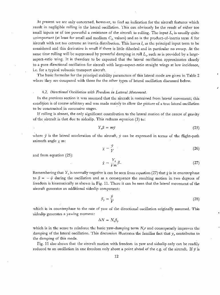
At present we are only concerned, however, to find an indication for the aircraft features which
result in negligible rolling in the lateral oscillation. This can obviously be the result of either too
Small inputs or of too powerful a resistance of the aircraft to roiling. The input L r is usually quite
{mimportant (at least for small and medium C L values) and so is the product-of-inertia term E for
aircraft with not too extreme an inertia distribution. This leaves l~ as the principal input term to be
considered and this derivative is small if there is little dihedral and in particular no sweep. At the
same time rolling will be suppressed by powerful damping in roll L~ such as is provided by a large-
aspect-ratio wing. It is therefore to be expected that the lateral oscillation approximates closely
to a pure directional oscillation for aircraft with large-aspect-ratio straight wings at low incidence, i.e. for a typical subsonic transport aircraft.
The basic formulae for the principal stability parameters of this lateral mode are given in Table 2
where they are compared with those for the other types of lateral oscillation discussed below.
4.2. Directional Oscillation with Freedom in Lateral Movement.
In the previous section it was assumed that the aircraft is restrained from lateral movement; this condition is of course arbitrary and was made mainly to allow the picture of a true lateral oscillation to be constructed in successive stages.
I f rolling is absent, the only significant contribution to the lateral motion of the centre of gravity of the aircraft is that due to sideslip. This reduces equation (3) to:
Yofi = my (25)
where .~ is the lateral acceleration of the aircraft, 3) can be expressed in terms Of the flight-path azimuth angle X as:
X - V (26)
and from equation (25):
Y ~ fi (27) 2 -- Vm "
Remembering that Y,~ is normally negative it can be seen from equation (27) that 2 is in counterphase
to 13 = - ~b during the oscillation and as a consequence the resulting motion in two degrees of
freedom is kinematically as shown in Fig. 11. There it can be seen that the lateral movement of the aircraft generates an additional sideslip component:
(28) G = V
which is in counterphase to the rate of yaw of the directional oscillation originally assumed. This sideslip generates a yawing moment:
AN = N ~
which is in the sense to reinforce the basic yaw-damping term N,,r and consequently improves the damping of the lateral oscillation. This discussion illustrates the familiar fact that yv contributes to the damping of this mode.
Fig. 11 also shows that the aircraft motion with freedom in yaw and sideslip only can be readily reduced to an oscillation in one freedom only about a point ahead of the c.g. of the aircraft. I f y is
12
the amplitude of the lateral displacement and ¢ the corresponding amplitude in yaw during an
oscillation the distance of this instantaneous centre of rotation (if forward speed is ignored) from
the c.g. is given by: X0 = 37/~, ~ . (29)
providing these two components of the motion occur in phase with one another, which is true for the simple mode under discussion. Assuming that the additional sideslip/2f created by the lateral movement is small in comparison with ~b = -/3~ (in Fig. 11 the lateral displacement is exaggerated
for pictorial clarity) one can see that ~ ~ - ]~ coincides with the maximum acceleration y as defined in equation (25). Then using the relationship that the amplitude in acceleration -J?(2rr/T¢,) 2~,
equation (29) dan be expressed as: X 0 38"9 t T~ViI2 (30) b/2 - Y~ bW/S I 100
For more orthodox aircraft (as distinct from the configurations discussed later as inertially slender) the 'indicated wavelength' of the lateral oscillation, Tf, Vi, is practically constant for a given design, which thus possesses an instantaneous centre of the lateral oscillation which is fixed for all flight conditions. For this type of aircraft, where the period T is determined by ndi( J only, equation (30)
can be reduced to: Xo ~ Yv (31) hi2 n~/i c
This parameter is of interest to the aircraft designer as it represents a locus--usually well within the physical length of the aircraft--where no lateral accelerations are perceived in the latera !
oscillation. It can be shown that this is also true in a' dutch roll with rolling, as the gravity term, though affecting the aircraft motion, acts equally on all the component parts of the aircraft including the occupants and can therefore not be detected by any sensing mechanism that is fixed to the
airframe, rather than to the outside world. The existence of an instantaneous centre of the lateral oscillation (and also of an analogous
centre for the short-period pitching oscillation) is of practical significance in the following w a y s :
(i) Near the centre,, flight will be most comfortable for the occupants.
(ii) The pilot's physical perception of the lateral oscillatory mode will change sign depending on the relative positioning of the cockpit. This applies equally to lateral bodily movements and to piloting with reference to the slip indicator and may become important in configura- tions where lateral control is exercised primarily through the dutch-roll mode. (See Section 6.2.)
(iii) A lateral accelerometer installed at the instantaneous centre will be insensitive to the dutch- roll mode and may be utilised for an automatic stabiliser designed to alter the effective
static n~ o f the aircraft without affecting the dutch-roll stability.
e This relationship is strictly true only for an undamped sinusoidal oscillation but in Ref. 5 it is shown that it is still valid for the degree of damping normally present in a lateral oscillation. If we assume
y = 37 sin (o~t)
= cos i t)
y = -37 o 2 s in (o t)
13
4.3. The 'Lanchester' Oscillation.
Another simple type of lateral oscillation is possible if freedom exists only in roll and in lateral
displacement. This motion was originally and rather mistakenly perceived by Lanchester as the essential mechanism of the lateral oscillation. It will be shown to be a type of motion requiring very unusual aircraft features and it can have occurred only in very isolated cases. However, in inertially slender configurations, a second oscillatory mode is sometimes found to appear at high
incidence, replacing the more normal spiral and roll subsidence, and this mode displays many of the features attributed to what is here described as the pure Lanchester oscillation.
The essential restriction defining this mode, which always has a relatively long period, is the
absence of yawing. This condition can only be satisfied if the aerodynamic yawing moments
generated during the oscillation are insufficient to induce a significant response in yaw, possibly because the inertia in yaw is too large to permit such a response.
If yaw is ignored, the motion is described by the two equations:
L~p = A b - L~p (32)
Y~/3 + Lift ~ = rn)7. (33)
If one assumes the aircraft to perform initially a rolling oscillation, the term (Lift 6) in (33) will generate a lateral movement in accordance with
Lift ~b = my (34)
This results in the motion illustrated in Fig. 12. It is seen that the sideslip resulting from the lateral plunging motion is in phase with the originally assumed roll. Equation (32) shows that this condition is only possible if inertia in roll is zero. In this case equations (32) and (33) describe a physically feasible oscillatory system with the period:
T = Vi22 .75 /{ bW/S N/ \ ~ ] " (35)
This mode can be more readily understood if one considers the lateral movement of the aircraft centre of gravity as the principal freedom. Then the mass can be regarded as the inertia of the
system, Yv, as the damping term resisting the motion and the restoring force is provided by the horizontal lift component which depends of course on the fact that the rolling motion is coupled to the lateral movement of the aircraft as shown in Fig. 12. Numerical expressions for the stability parameters of this rather unusual form of dutch roll are given in Table 2.
4.4. Conventional Dutch Roll.
We come now to consider the most general type of a laterai oscillation in three degrees of freedom, the motion which in fact one visualises when speaking of a dutch roll. In the conventional approach to this mode it is still assumed that the principal freedom is yawing and that the participation of the other two freedoms--hlthough kinematically very noticeable--has only a modifying influence on the stability of the mode. Analysis , as in the cases discussed previously, will again be in stabi!ity axes, which implies that aerodynamic phenomena predominate over gyroscopic moments.
To study the mechanism of this motion, it is convenient again to assume that the aircraft first performs a pure directional oscillation as described in Section 4.1. If the wing has sweep or dihedral, a rolling moment L~[3 is generated as the aircraft yaws and consequently to satisfy the equilibrium in roll:
Lv~ = A p - L~p . (36)
14

The aircraft responds by also oscillating in roll. If the aircraft does not generate any signific ant cross-coupling effects to react back into the originally assumed yawing oscillation, the dutch roll described so far differs only kinematically but not dynamically from a pure directional oscillation. In practice this is of course not so and we shall now consider a more realistic situation in more detail. In order to simplify the discussion the following analysis will consider two extreme cases,
although in practice a dutch roll will contain elements of both these features simultaneously.
(i) Aircraft with inertia in roll negligible when compared with damping in roll, i.e.
(ii) Damping in roll negligible when compared with inertia in roll
linv
We expect to find the conditions of the first class approached by high-aspect-ratio aircraft and aircraft flying at low altitudes. Approaching the second class are the modern highly loaded
small-aspect-ratio designs flying at high altitudes.
4.4.1. Aircraft with large damping in roll when compared with inertia in rolL--In the extreme
case we ignore inertia in roll so that equation (36) reduces to
Lv/3 = - L~p. (37)
Equation (37) is satisfied if (as both Lv and Lp are normally negative) rate of roll is in counterphase to sideslip, i.e. in phase with yaw during the oscillation, as to a very good degree of approximation ~b = - / 3 in a typical dutch roll. This results in the motion sketched in Fig. 13, considering major
terms only in the side-force equation:
Lift ¢ = my (38)
and it can be seen that the roiling generates a lateral plunging motion, which is in counterphase to angle of bank; the amplitude of this motion is again exaggerated in Fig. 13. As was seen previously in Figs. 11 and 12 this plunging motion results in additional sideslip/3~ = ~L = ~/V which occurs in phase with, and is therefore additive to, the sideslip generated by the yawing motion/3¢, = - ~. As a consequence the effective restoring moment acting on the yawing aircraft is increased to Nv(/3C~+/3L) and thus the frequency of the lateral oscillation is increased by the dutch-roll contribution. On the other hand, as no additional yawing moments are created in phase with the rate of yaw of the yawing motion, the damping of the basic directional oscillation is not affected
in this type of dutch rolling. So far secondary effects such as those produced by the cross-coupling derivatives lr, n~, and the
product-of-inertia term iE, have been ignored, but they must indeed be expected to influence the stability of the dutch roll of the aircraft. The condition in which the product-of-inertia terms become dominant in the lateral oscillation will be shown later to create a kinematically quite distinct type of dutch roll so that it need not be covered here, remembering of course that neither of these simplifications will ever strictly apply. Of the aerodynamic cross-coupling terms, n~, the yawing moment due to rate of roll must, however, be considered as an important factor in the typical dutch roll under consideration. Its effect can be readily assessed by reference to Fig. 13. As rate of roll is in
15

counterphase to sideslip, the yawing moment produced by n o is additive to the yawing moment due to sideslip. If n o < 0 the effective restoring moment is thus increased and if n o > 0 the frequency is reduced.
4.4.2. Aircraft with inertia in roll large compared with damping in rolL--In the extreme case we now ignore l o and thus
Loft = A15. (39)
Now as Lv is usually negative, acceleration in roll is in counterphase to sideslip and the dutch roll is as illustrated in Fig. 14. When compared with the motion shown in Fig. 13 the rolling motion now lags the yaw motion by another 90 °. So in consequence does the additional sideslip generated by the
lateral movement induced by the rolling motion. The yawing moment (Nv3z) associated with this
sideslip 3r ca11 be seen in Fig. 14 to oppose the original damping in yaw (N,r), thus reducing the
damping of the dutch roll. It is readily seen that this effect is proportional to loll x and to C L. As the
product of these terms almost invariably increases with incidence the damping of the lateral oscillation for this type of aircraft always deteriorates with incidence and eventually leads to instability. This is of course a phenomenon familiar to the student of lateral stability.
Applying the reasoning used in the previous section it is also apparent that n o now affects the damping, negative n~, being detrimental. A s normally n o becomes increasingly negative with increasing CL, the basic loss in damping with incidence analysed above is further accelerated by n o.
Approximate formulae for the stability parameters of the dutch-roll oscillation, taking both inertia in roll and damping in roll into account, are given in Table 2, in the section referring to the classical form of the dutch-roll oscillation.
In the cases discussed so far the lateral oscillation has always been well described by emphasis on the aerodynamic features, and in no case did gyroscopic moments play a significant part. In the discussion of the 'classical dutch roll' it was, however, mentioned that product-of-inertia terms may be significant and in many cases even dominating. We have shown in the introduction that if this
is the case, analysis becomes simpler if principal inertia axes are chosen as the reference system. In the following section we shall see that by kinematically restraining the aircraft to roll about the principal inertia axis only, a simple motion emerges that very closely resembles the dutch roll of certain types of modern aircraft.
4.5. Pure Rolling Oscillation.
If an aircraft is restricted to rolling only about the longitudinal stability axis, no restoring moment is generated (there is no L¢ derivative) and as a consequence within this freedom no oscillatory mode is contained. However, if rolling is assumed to occur about a body axis, which is inclined to the flight path at an incidence %, kinematically sideslip is generated according to the following law:
/9¢ = sin ~0 sin CB. (40)
If CB is defined as the roll angle about the body axis:
cB = fp dt (41)
and at the same time (see Fig. 5) incidence varies as:
= - % ( 1 - c o s - % 2 " ( 4 2 )
16 ̧
Remaining within the limits of small perturbations, the latter term can be ignored and it is again
possible to separate the longitudinal and lateral motions e. Within the limits of linear theory the
sideslip generated by this rolling motion produces a rolling moment Lvfl¢, so that from equation (40)
Cz = l¢¢B = lv sin ao¢ B . (43)
Thus 1¢ = l v s in% is effectively a restoring moment in roll if l~ < 0 and the motion within this restricted freedom is oscillatory as illustrated in Fig. 15. Damping of this mode is provided by ls) and
the dutch-roll ratio is simply given by the kinematic relationship:
l ¢/fl = sin%" (44)
The stability parameters of this mode can be obtained from the rolling-moment equation:
LvB sin % f PB dt + L~BpB -- A]) B = O.
The results are given in Table 2, and it is interesting to note that the period (assuming the effect
of the damping is negligible) is given by:
V i sin s 0 ZvBi~/"
Having shown that rolling about the principal inertia axis generates a physically feasible lateral
oscillation, it remains now to demonstrate that there are configurations with characteristics favourable
to the establishment of this mode. The essential restraint for this motion to occur is that yawing
(in principal inertia axes) must be practically absent. This will be true if inertia in yaw (in comparison
with inertia in roll) is large, and if the yawing moments generated during the rolling motion are
small. From the previous discussion it may be seen that two yawing-moment contributions are
activated in the rolling oscillation,
(i) weathercock stability nv, i.e. AN = No~fi
(ii) yawing moment due to rate of roll AN = N~p.
From Appendix I, nv, in principal inertia axes is:
n~B = n~ cos ~ + l~ sin ~. (46)
For positive incidence %B < nv; numerical examples are given for two typical modern configurations
in Fig. 16. l v is seen there to be hardly sensitive to axis transformation; n~ however is considerably reduced at high incidence, and this helps to satisfy the conditions required for the establishment of a
dutch roll that is virtually pure rolling. The derivative n~ becomes even more insignificant for
the type of aircraft considered when expressed in body axes as shown in Fig. 17.
e It should be noted, however, that this effect must be considered if large-amplitude oscillations or responses to large inputs are investigated. For instance, it has been observed in the flight of a model that a basically laterally unstable configuration settles down to a dutch roll with a large steady amplitude. In this case the instability was largely caused by Iv, and as this derivative is reduced as incidence decreases the oscillation builds up to a bank angle which results in a reduction in incidence, and thus in lv, sufficient to reach a quasi-steady equilibrium.
17
(87541) B

Finally and most important perhaps, inertia in yaw must be much larger than inertia in roll for
the lateral oscillation to degenerate into a practically pure roiling oscillation. The trend of the ratio
of C/_d for typical service fighter aircraft over the last three decades is indicated in Fig. 18 and it is
apparent from this graph that the modern aircraft has become increasingly more 'inertially slender',
a feature obviously encouraging the type of lateral oscillation discussed here. So far freedom in lateral
motion has been ignored and in the following section it will be shown to influence the damping of
this lateral mode, without materially affecting otherwise the basic mechanism of this motion.
4.6. Rolling Oscillation with Lateral Freedom.
If the effect of bank on the lateral motion of the aircraft as defined in equation (25) is included,
the motion illustrated in Fig. 19 results. The additional sideslip/?L generated bythe lateral movement of the centre of gravity coincides in phase with the rate of roll of the basic rolling oscillation.
Consequently the 'natural damping' of the motion (L,2)p) of the mode is opposed by a rolling moment (L~/?L). The stability parameters of this more realistic form of lateral oscillation,
degenerated into what is described here as a rolling oscillation, are given in Table 2. It can be seen that the motion is unstable if
cL - - > . . ( 4 7 ) 2 sin % z j0
The values for the period and dutch-roll ratio are for this mode--within the general accuracy of the
simple analysis conducted--identical with those obtained for the pure rolling oscillation {equations (44) and (45)}.
In the following section a numerical criterion will be established to indicate when this extreme form of lateral behaviour can be expected to become prominent.
5. Applicability of the Concept of an Inertially Slender Configuration.
To test the various simple models proposed here for approximating the dutch-roll characteristics
of an aircraft, and to determine if possible a parameter for predicting the conditions in which the
various types of lateral oscillations apply, the three following typical configurations have been
chosen as numerical examples:
(i) a tailed aircraft with 45 ° sweep
(ii) a tail-less delta with 60 ° leading-edge sweep
, (iii) a narrow- deka of aspect ratio 1.
The exact solutions for the period (in terms of indicated wavelength), the dutch-roll ratio ~//3 and the damping of the lateral oscillation for these aircraft are given inFigs. 20 to 22. They are there compared with the simple approximations derived earlier in this report for what was called the 'classical dutch roll' and the 'rolling oscillation with lateral freedom' respectively. At low incidence the solution based on the kinematic model of the simplified dutch ro!l is in good agreement and at the other end, for very high incidence, the approximation based on the concept of a rolling oscillation about the principal inertia axis becomes an obviously fair approximation, in particular for the more slender designs. In between these extremes there exists a regime where the lateral motion of the aircraft contains elements of both simPlified modes and neither of the two approxi- ,mations applies. The two simple approximations may be crudely interpreted as asymptotic forms, which the actual latera[ motion approaches at the extremes of the C L range.: As the true lateral motion through the incidence range gradually changes from a simple dutch roll to a simple rolling
18

oscillation, a good indication of the general trend of development of the motion, and the level of the stability of the lateral oscillations of an aircraft, is given by the boundaries formed by these asymptotes.
On closer inspection Figs. 20 to 22 show a marked common feature. The intersection between the
two approximations for the wavelength occurs in every case in the region where both estimates are equally unreliable and as one moves in either direction from this value the simple approximations become increasingly representative. The intersection defines a particular value of incidence:
It can now be said that if the incidence of the principal inertia axis, ~ < aB, the lateral oscillation can be well represented by the model of a simple dutch roll, and at incidence a >> c¢ B the motion degenerates into a rolling oscillation 'about the principal inertia axis.
In practice, from the trends shown in Figs. 20 to 22, one may expect simple approximations using the kinematic concept of the classical dutch roll to give a representative picture of the lateral behaviour
of an aircraft if ~ < 2/3c~B, and conversely expect the lateral motion to be governed by the type of motion described as the rolling oscillation if ~ > 4/3~ B. As the change between these two conditions must be gradual, a fair idea of the stability of the lateral oscillation throughout the full incidence range may be obtained by drawing a smooth curve which uses the two approximations as asymptotes.
This procedure, as illustrated in Fig. 23, could be adequate for a very early assessment of a new
design, when generally dependable data for the aerodynamic and inertial properties are not available anyway and more accurate and laborious analysis would be of doubtful value.
The criterion proposed in equation (48) is of course not simply the rather accidental intersection
between the approximate solutions, but reflects rather a basic physical phenomenon. The principal feature of an oscillatory motion is its periodicity and the principal feature of a physical systmn to
make it oscillatory is the restoring force acting on it. It can be said, therefore, that the nature of an oscillatory mode is determined by the predominant spring restraint in the system. In the preceding discussion of the various possible forms of lateral oscillations it was shown that there are primarily
two potential 'springs' contained within the lateral freedoms of the aircraft, each generated by a kinematically distinct motion. Equation (48) now compares the relative 'stiffness' of these two
springs and states that the nature of the actual lateral oscillation performed by an aircraft is determined by the stronger of these two potential spring restraints; in other words, of the possible extreme forms of the motion, that entailing the higher frequency tends to predominate.
Now the lateral motion described above as a rolling oscillation is only of interest if it exists within the practical incidence range of the aircraft considered, i.e. if ~max > 4/3~B- Equation (48) shows that there are three essential features which make an aircraft liable to this form of lateral motion:
(i) a large ratio of inertia in yaw to inertia in roll C/A, i.e. an inertially slender layout
(ii) a large ratio of l~/no; this is associated with large wing sweep and high C L
(iii) large flight incidence a, which is associated with small-aspect-ratio wings.
The type of aircraft featuring all these characteristics simultaneously is obviously an aircraft designed for supersonic speeds, flying at high incidence, in particular in the approach.
6. The Principal Features of the Lateral t]/Iotion of an Inertially Slender Aircraft.
From the analysis in this report it has become apparent that when an inertially slender aircraft flies at sufficiently high incidence, the character of the lateral oscillation changes from that of the
19 (87541) B*
familiar dutch roll to a dynamically and kinematically quite distihct special form, described as the rolling oscillation. As this phenomenon is essentially a radical departure from the lateral motion as it is generally perceived, it appears worthwhile to consider this motion in some detail. It may affect not only stability but also lateral control, and may demand a new approach in the design and operation of an aircraft governed by this lateral mode. At this stage the discussion must by necessity be exploratory and tentative, as it is not yet backed by much practical experience.
6.1. The Lateral Oscillation. The fully established rolling oscillation is effectively defined by the rolling-moment derivatives
lvB and l~R, and by the inertia in roll. It is also to be expected that the unsteady derivatives loB, and l~B can have a significant influence on the stability of this mode, but reliable numerical data for
these are lacking at the present time. Of the aerodynamic derivatives lvB is the most powerful, generating the restoring moment to give
the period of the oscillation as approximately:
T - 16.08V, ~ / ( sinb% I~/W/S 1 • (49)
Although the principal kinematic features and thus the period and dutch-roll ratio of the motion are adequately defined by the rolling-moment equation only, the damping of this mode is also affected significantly by the aircraft response in a second freedom, the lateral motion. Retaining again only major terms this gives the following expression for the logarithmic decrement of the mode:
l~B + 0" 307 CL S = - 0"614 i~° sin~0 (50)
\i~0 b~
where l~B is normally damping and the C L term destabilising. The dutch-roll ratio is completely independent of aerodynamic effects and expresses only the kinematic co-ordination of bank and
sideslip: ¢ _ 1 (51)
-- sin%"
Whereas .with the conventional swept-wing aircraft the dutch-roll ratio tended to increase with both incidence and altitude, for the inertially slender aircraft it decreases with incidence and is independent
of height. The period of the lateral oscillation for a more conventional configuration is roughly proportional
to the inverse of V i (TVi = const.). For an inertially slender aircraft with a highly swept wing, l~ is approximately proportional to ~, and from equation (49) we get
1 T (52) Via"
On a slender wing lift will generally be non-linear as approximated by:
CL = - ~ - ~ - o~ + - U J "
20
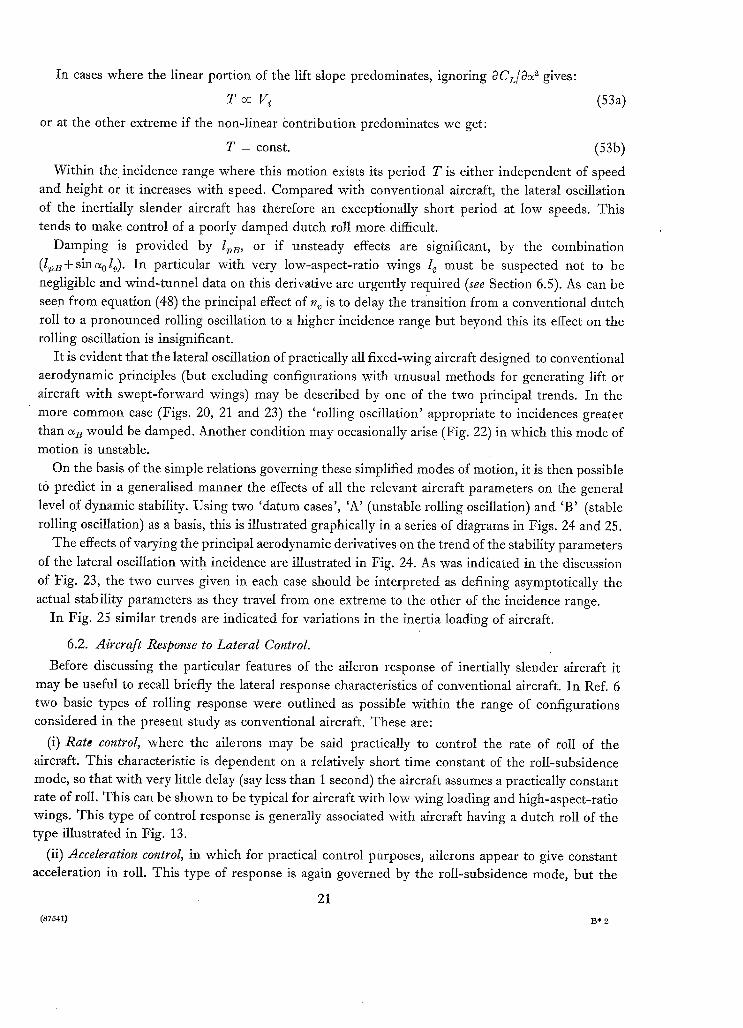
In cases where the linear portion of the lift slope predominates, ignoring OCz/O~ ~ gives:
T (53a)
or at the other extreme if the non-linear contribution predominates we get:
T = const. (53b)
Within the incidence range where this motion exists its period T is either independent of speed and height or it increases with speed. Compared with conventional aircraft, the lateral oscillation
of the inertially slender aircraft has therefore an exceptionally short period at low speeds. This tends to make control of a poorly damped dutch roll more difficult.
Damping is provided by l~e, or if unsteady effects are significant, by the combination
(l~B+sinaol~). In particular with very low-aspect-ratio wings l e must be suspected not to be negligible and wind-tunnel data on this derivative are urgently required (see Section 6.5). As can be seen from equation (48) the principal effect of n v is to delay the transition from a conventional dutch roll to a pronounced rolling oscillation to a higher incidence range but beyond this its effect on the rolling oscillation is insignificant.
It is evident that the lateral oscillation of practically all fixed-wing aircraft designed to conventional aerodynamic principles (but excluding configurations with unusual methods for generating lift or aircraft with swept-forward wings) may be described by one of the two principal trends. In the more common case (Figs. 20, 21 and 23) the 'roiling oscillation' appropriate to incidences greater than a B would be damped. Another condition may occasionally arise (Fig. 22) in which this mode of motion is unstable.
On the basis of the simple relations governing these simplified modes of motion, it is then possible
to predict in a generalised manner the effects of all the relevant aircraft parameters on the general
level of dynamic stability. Using two 'datum cases', 'A' (unstable rolling oscillation) and 'B' (stable rolling oscillation) as a basis, this is illustrated graphically in a series of diagrams in Figs. 24 and 25.
The effects of varying the principal aerodynamic derivatives on the trend of the stability parameters of the lateral oscillation with incidence are illustrated in Fig. 24. As was indicated in the discussion
of Fig. 23, the two curves given in each case should be interpreted as defining asymptotically the
actual stability parameters as they travel from one extreme to the other of the incidence range. In Fig. 25 similar trends are indicated for variations in the inertia loading of aircraft.
6.2. Aircraft Response to Lateral Control.
Before discussing the particular features of the aileron response of inertially slender aircraft it may be useful to recall briefly the lateral response characteristics of conventional aircraft. In Ref. 6 two basic types of rolling response were outlined as possible within the range of configurations considered in the present study as conventional aircraft. These are:
(i) Rate control, where the ailerons may be said practically to control the rate of roll of the aircraft. This characteristic is dependent on a relatively short time constant of the roll-subsidence mode, so that with very little delay (say less than 1 second) the aircraft assumes a practically constant rate of roll. This can be shown to be typical for aircraft with low wing loading and high-aspect-ratio wings. This type of control response is generally associated with aircraft having a dutch roll of the type illustrated in Fig. 13.
(ii) Acceleration control, in which for practical control purposes, ailerons appear to give constant acceleration in roll. This type of response is again governed by the roll-subsidence mode, but the
21
(87541) 13" 2

time constant is now of the same order or even longer than the duration of a typical roll manoeuvre. This trend, which becomes more noticeable with altitude, is generally associated with small-aspect- ratio wings, high wing loading, and large inertia in roll. In other words it is a feature of aircraft with
dutch-roll characteristics of the type illustrated in Fig. 14. The two basic types of roll response following a sudden aileron application are illustrated in
Fig. 26 and compared with the corresponding response of the inertially slender aircraft. The extreme
case shown is of course the idealised response of an inertially infinitely slender configuration for which C/A -> oo. In this case the aircraft is virtually constrained to roll about the principal inertia
axis only, and if this is at an incidence, ~ > 0, there is a restoring restraint arising from kinematically
induced sideslip acting on the aircraft, so that in this freedom the quantity describing the steady
response is a bank angle, i.e. ailerons act as a position control. The aircraft response according to this
simplified model is governed by the equation:
sin ~ .[ PB dt + L~BPB -- Ao])B = L~B~, (54) L~B
i.e. it behaves as a second-order system, unless the first term (the restraining moment) is small compared with the damping and the mode is critically damped. At small incidence equation (54) again has the familiar roll subsidence as a solution. This phenomenon reflects of course the fact that in practice the response in roll of an aircraft is governed at low incidence by the roll subsidence but at high incidence (if otherwise the conditions to make it inertially slender are satisfied) by the lateral
oscillation. In Appendix III the principal parameters describing the roll response of an inertially slender
aircraft are derived. The most important parameter associated with the rolling oscillation is the
'quasi-steady bank angle' in response to aileron,
It should be noted that equation (54) is linearised for small bank angles, say .fp dt < 30 °. As frequently manoeuvres to larger bank angles are demanded, it is also necessary to consider for
generality the more correct form:
L~B sin c~ sin j" p~ dt + L~BpB -- A2b B = L~B~. (56)
The actual response of this non-linear system is now no longer proportional to ~. If the aileron input is expressed in a general form by the 'quasi-steady bank angle' demand ~b~ defined,in equation (55), the roll response changes in character as aileron is progressively increased in the manner
illustrated in Fig. 27. The most noticeable effect is the sudden change in the response when the bank angle anywhere during the motion exceeds 90 ° . Beyond this point the aircraft, now assisted
by a negative restraint, assumes an unexpectedly violent rolling motion. This phenomenon ought to be considered in the design of an inertially very slender aircraft, in particular of small aircraft expected to perform fairly rapid manoeuvres, although there is no record of this tendency yet being
observed in flight. So far the discussion has been restricted to an idealised case where the roll response is fully
and solely determined by the oscillatory mode. In practice, however, aircraft, even at relatively high incidence, also respond in the roll-subsidence mode, the actual response being the super- imposition of the two contributions to the rnotion as shown in Fig. 28. If the time constant of the
22

roll subsidence is much smaller than the corresponding effective time constant (say half the period
of the lateral oscillation) of the response in the oscillatory mode, the roll subsidence is of greater consequence from the piloting point of view. The inverse is of course true if the aircraft responds
more rapidly in the oscillatory mode so that, at least initially in the manoeuvre, the aircraft response
is dominated by the rolling oscillation. In Appendix III it is shown that for configurations which are, in the sense of the criterion for the
lateral oscillation, inertially slender, the steady rate of roll associated with the roll subsidence is
approximately given by: lib %B 2V (57)
P --~ ~ lv-B )rB b sin ~0"
It is interesting to note that with the inertially slender aircraft the quasi-steady roll response is now largely governed by yawing moments. It was shown earlier that the lateral oscillation of inertially
slender aircraft is practically dominated by rolling moments and in consequence for this type of aircraft, rolling freedom and yawing freedom have virtually reversed their customary association
with the two principal lateral modes. The roll-response parameters have been computed for the aircraft defined in Table 3 and plotted
against incidence in Figs. 29 to 30. Fig. 29a shows that the quasi-steady bank angle in response to ailerons decreases as the incidence is increased. For the example quoted, this quasi-steady bank angle that can be obtained initially by aileron application is less than the aileron angle at incidences a > 15 °. This may constitute a severe restriction in the lateral manoeuvrability for an inertially
slender aircraft. In Ref. 11 this trend was indeed criticized by pilots on a modern delta aircraft and recent detailed response calculations for a hypothetical slender-delta aircraft have also
confirmed this point. The steady rate of roll ultimately attained when ailerons are held long enough has been computed
from Appendix III and the results are plotted in Fig. 29b, where data obtained from the approximate
form in (57) are compared with predictions based on the conventional approximation
/~ (1 n~l~)2V (58)
At low incidence, ~ ~ ~,, equation (58) obviously gives a reliable answer, but, at the other extreme of the C L range, the conventional estimate is very optimistic. This shows how the influence of the
aircraft inertia distribution drastically reduces the potential rolling performance of the inertially
slender aircraft. The time constant t v of the roll subsidence for this aircraft has been determined by solving the
stability quartic, as no simple approximation appeared to be satisfactory. Results are given in
Fig. 30. It can be seen that the response lag approaches a value of 4 seconds at high incidence and that the values of the lag increase inversely as ~/~ with altitude. These response lags are very large
compared with the effective response time of the aircraft as governed by the oscillatory mode (say 1/4 of the period of the lateral oscillation) and in general larger than the duration of most practical rolling manoeuvres. It is apparent that for such aircraft the roll-subsidence mode has little effect
on the lateral-control response at low speeds. It is also worth noting that from the results presented in Fig. 30 for this configuration the roll
subsidence combines with the spiral mode at incidences e~ > 22 ° to form a second lateral oscillation with a relatively long period. This mode resembles in some respects the type of lateral oscillation described previously as the 'Lanchester Oscillation'.
23
The power of the rudder of this aircraft as a roll control is examined in Appendix IV and steady
rates of roll in response to rudder have been computed for the aircraft defined in Table 3. Results are plotted in Fig. 31 and compared with the corresponding aileron power. As incidence increases,
the effective aileron power deteriorates rapidly until at ~ > 18 ° the rudder becomes the more
effective lateral control. These results suggest the use of both controls simultaneously for lateral control. If the two controls
are interconnected with a gearing of 1:1, the combined rolling power is as illustrated by the dashed
curve in Fig. 31. The obvious advantage of this scheme is that the variation of the lateral-control
power vcith incidence is substantially reduced.
In order to obtain the maximum benefit from this arrangement, it is desirable to reduce the parasitic direct rolling moment of the rudder surface 1¢. As this rolling moment is produced largely by the
outboard portion of the rudder span, l; can be reduced by using the lower part of a split rudder only
as a part of the lateral-control circuit. The top half of the rudder and whatever portion of the total
travel of the lower half is required for directional control is connected to the rudder pedals. Such a
scheme is illustrated in Fig. 32. The principal virtue of the type of lateral control outlined above is to
tend to restore to an inertially slender aircraft a more ideal type of roll response, i.e. rolling about the
flight-path axis. This not only improves the effective rolling power, but also helps turn co-ordination
by swinging the nose of the aircraft into the direction of the ~ntended turn.
Rolling about the principal inertia axis leads not only to an undesirable development of sideslip but at the same time to a loss of incidence. Fig. 33 shows the incremental incidence which has to be applied (by the use of elevators) to achieve co-ordinated turning flight after the aircraft has rolled
to the desired bank angle. Two cases are considered:
(i) a conventional aircraft which is assumed to roll about its flight-path axis, so that no incidence is lost as a result of the rolling motion
(ii) an inertially slender aircraft which is assumed to roll about its principal inertia axis. I t is assumed in this graph that the static longitudinal stability (in relation to inertia in pitch)
is too small to be able to restore incidence trim within the time required to roll the aircraft. I t can be concluded that the inertially slender aircraft demands not only a fairly powerful form
of rudder co-ordination but may also need relatively more elevator to speed the entry into a banked
turn.
6.3. Response to Lateral Gusts.
The initial response of an inertially slender aircraft to a lateral gust with the velocity vg is
determined by the roiling moment
= lvB % (59)
and is therefore similar to the response to aileron. Assuming in this simplified analysis freedom in roll only, the aircraft comes to rest at a bank angle, which kinematically creates a sideslip sufficient
to cancel fig = vg/V: thus,
fig + fi~ =F:V~ cos ~ + % sin ~ = 0 (60)
and
v, (61) tan ~bg V%"
24

With the assumption that % is identical to the aerodynamic incidence c~, equation (61) has been computed for a representative range of parameters and is plotted in Fig. 34. This simple picture, which is of course only relevant for an inertially slender aircraft at incidences ~ >> sin-~{. - (ndl,)(A / C)}, shows a rather surprising trend. The equilibrium bank angle for a given gust velocity is inversely
proportional to incidence and is independent of l v. Although an obviously important criterion, the 'equilibrium bank angle' ~ does not fully define the response of an inertially slender aircraft to a side gust. In Fig. 35 approximate time histories are presented of the roll response to a 20 ft/sec
side gust of the aircraft defined in Table 3 flying at 5 °, 10 °, 15 ° and 20 ° of incidence. Although at low
incidences the final bank angles are much larger, the initial response of the aircraft to the same gust
is more rapid at high incidence, giving the pilot less chance to counteract.
6.4. Automatic StabiIisation.
To design an efficient stability augmenter it is necessary first to study the actual aircraft motion so
as to apply control signals where they are most effective. With conventional configuration, in which the inertia distribution is not too extreme, the 'natural
damping' of the dutch-roll mode is provided by n~ (and 3b); a logically designed autostabiliser for
this aircraft should be so arranged as to supplement the natural aircraft damping by means of, for example, a yaw damlYer. Similarly the damping of the roll subsidence, and in consequence also
the lateral-control characteristics would be improved by a roll damper. With inertially slender configurations the lateral oscillation has been shown to have virtually no
yawing component, so a yaw damper would obviously be of little consequence to the motion. In fact the principal effect of a yaw damper would be to further suppress any yawing-motion tendency and
thus to establish an even 'purer' rolling oscillation. The most potent aerodynamic parameter in the lateral oscillation of the inertially slender aircraft
is lv; reduction of l~ by artificial means may therefore be the most satisfactory way of restoring more conventional lateral behaviour to such designs. It has also been shown that (-I9) is a potential damping term for the dutch roll of this type of aircraft, and a signal input of this form may be
readily generated by a phase-delay in an artificial (+ lv) stabiliser. Direct damping of the lateral oscillation of the inertially slender aircraft occurs through lv and
artificial roll damping is therefore the logical choice for stabilising this mode.
6.5. Wind- Tunnel Testing.
The techniques of wind-tunnel testing and of the presentation of aerodynamic data have developed round the needs of the aerodynamicist and the aircraft designer. This process has obviously been influenced also by the particular problems of the aircraft types of the past three or four decades. The aircraft of this" era were generally characterised by non-extreme inertia distribution so that
aircraft dynamic behaviour was largely determined by aerodynamic effects. Analysis of 'conventional'
aircraft behaviour is indeed well served by the system of stability axes. As the inertially slender aircraft has such distinct preference for moving about principal inertia
axes and analysis was shown to be greatly simplified by reference to these axes, one may well wonder if better aerodynamic information could not be obtained from wind-tunnel test orientated to body axes. In Appendix I formulae are given for converting aerodynamic derivatives to any chosen system of axes. I f all derivatives are known this conversion is basically only a matter of arithmetic.
25
Unfortunately only in the rarest cases is a complete set of, in particular, the rotary derivatives available. Rarer still do we know the unsteady terms l~ and n~, the former being potentially a dominating quantity in very advanced designs.
In practice the essential problem is to obtain the most relevant information from the smallest number of tests and in this case a judicious choice has to be made as to the opt imum design of such an experiment.
So far as the inertially slender aircraft is concerned, its principal lateral mode is roll about the principal inertia axis and it would appear that the most significant dynamic derivative referring to this motion is the effective damping in roll.
Unfortunately rolling about a body axis is not an 'aerodynamically pure' motion, as it generates roll and sideslip simultaneously (see Figs. 5 and 15). As a method for measuring isolated derivatives it is therefore unsuitable. However, as such a rolling motion very closely resembles the lateral motion of an actual aircraft, the combined 'effective' derivatives:
l ~ = l~ B + sin ~0 l~B (62)
= 10B - ( 6 3 )
extracted from such tests are likely to be more helpful to the designer than any tests on pure derivatives, such as measurements of l~ without l, o.
Using for example the technique of free oscillations on a model restrained to freedom in roll about
a body axis at incidence ~ to the direction of the flow, period P and damping time t o of the model with inertia Iro n give:
{/vB - /~ , z sin~} = - ( 2~ r~ 2/r°n (64) ~pV] pSbsine~
{lpB + sin c~ l~} -- 2 I~,o~ I tD pS(b/2) ~" (65)
7. Conclusions.
The kinematic and dynamic features of the lateral modes of motion have beendiscussed first for the conventional aircraft, i.e. aircraft in which aerodynamic effects predominate over gyroscopic moments. It has then been shown that for aircraft with a distinctly slender inertia distribution the dutch roll degenerates gradually into an almost pure rolling oscillation about the principal inertia axis as the incidence becomes greater than
A_t a = - sin -1 f l~B C}"
Crude analysis of the lateral behaviour of this class of aircraft is greatly simplified if principal inertia axes are used as the reference system.
The principal features of the lateral motion of the inertially slender aircraft ma y be summarised as follows:
(i) The lateral oscillation is practically a pure rolling oscillation about the principal inertia axis. The dutch-roll 'ratio is given by the kinematic relationship
¢/fi = 1/sin%
The period is inversely proportional to @(sin%le/i~l ) and, for a slender swept-wing aircraft,
proportional to V~, resulting in an unusually short period at low speeds. The damping is provided by l~, and perhaps in addition by l~.
26

(ii) Lateral control becomes predominantly position control; i.e. bank angle is controlled by aileron. In general the response to aileron deteriorates rapidly with increasing incidence.
(iii) Rudder is inherently more powerful as a lateral control at high incidence and becomes
indispensable for turn co-ordination.
(iv) The response to side gusts is again an almost pure rolling motion that may become very rapid
at low speeds.
(v) Artificial yaw damping becomes ineffective. The most promising stability augmentor would preferably produce artificial l~ or alternatively a combination of positive l. and - l~.
(vi) It is suggested that oscillatory rolling tests about the fuselage axis of a model may provide the most economic minimum aerodynamic information for reliable predictions as to the dynamic lateral
behaviour of the inertially slender aircraft. Finally simple formulae are given which permit crude estimates to be readily obtained with the
minimum of derivative information of the principal stability and control parameters of both inertially
non-slender and slender aircraft.
27
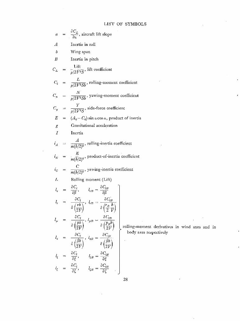
A
b
B
e L
q _
Cgb u
C y -
E =
g.
I
i ~ -
i U - -
L
g _
1, 0 D
LIST OF SYMBOLS
OCL aircraft lift slope ac~ '
Inertia in roll
Wing span
Inertia in pitch
Lift p/2V~S, lift coefficient
L p/2V2Sb, rolling-moment coefficient
N p/2V2Sb, yawing-moment coefficient
Y p/2V2S, side-force coefficient
(A 0 - Co) sin a cos a, product of inertia
Gravitational acceleration
Inertia
A re(b~2)2, rolling-inertia coefficient
E m(b/2)2, product-of-inertia coefficient
C m(b/2)=, yawing-inertia coefficient
Rolling moment (Lift)
aq aq~ 0/3' zv.- a5 oq aqk
aq aq.
a ~g a t 2 v / oq aq,~
,
aq aq.
aq aq~ at' l t~- at
rolling-moment derivatives in wind axes and in body axes respectively
28
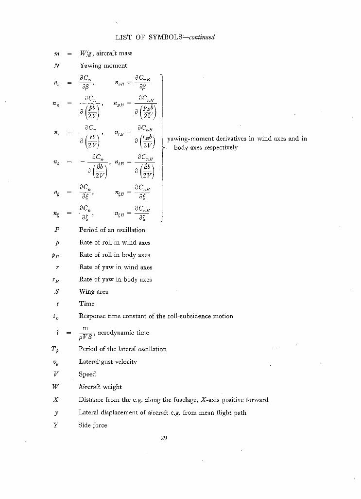
m
N
nv
n 2)
7/r
n~
n~
P
P
PB /,
rB
S
t
t~
Vg
V
W
X
Y
Y
LIST OF SYMBOLS--continued
= W/g, aircraft mass
Yawing moment
a C~ a C~B - ,9/~ ' n . o . - a/3
0 C~ 0 C,~B
0 ~V o 1 2 v !
aC~ aC.~B
a ~F a \ 2 v !
a C~ ~ C~B
a ~ a ~
- a ~ ' n , B - ~ :
a~ ac~B
Period of an oscillation
yawing-moment derivatives in wind axes and in body axes respectively
Rate of roll in wind axes
Rate of roll in body axes
Rate of yaw in wind axes
Rate of yaw in body axes
Wing area
Time
Response time constant of the roll-subsidence motion
m p V S ' aerodynamic time
Period of the lateral oscillation
Lateral' gust velocity
Speed
Aircraft weight
Distance from the c.g. along the fuselage, X-axis positive forward
Lateral displacement of aircraft c.g. from mean flight path
Side force
29

LIST OF SYMBOLS--continued
Yv
Y~
Y T m
- - 2 - - ~ Y k o B - -
I OCv i OOv
8 ~ O \2V]
y~ =
YC =
sag
Incidence
c ~ C.v
side-force derivatives in wind axes and body
axes respectively
c~ B
c¢ 0
Incidence of the principal inertia axis, above which inertially slender-aircraft theory applies (equation (36)}
Incidence of the principal inertia axis
Angle of sideslip
Logarithmic decrement of the lateral oscillation
Bank angle
Angle of yaw
~ 2
P(Po)
m pSb/2 ' relative density
Air density (at sea level)
= PIPo
S,#ces
B
g
0
Body axes
Gust
Principal inertia axes
30

No. Author(s)
1 William H. Phillips . .
2 W . J . G . Pinsker ..
3 W . J . G . Pinsker . . . . . .
4 A.R. Cawthorne and G. N. Stevens..
5 K . H . Doetsch . . . . . . . .
6 W . J . G . Pinsker . . . . . .
7 William Letko and Herman S. Fletcher
8 Lewis R. Fisher . . . . . .
9 Joseph L. Johnson Jr . . . . . . .
10 H . H . B . M . Thomas and S. Neumark
11 Maurice D. White and Robert C. Innis
R E F E R E N C E S
Title, etc.
Effect of steady rolling on longitudinal and directional stability.
N.A.C.A. Tech. Note 1627. June, 1948.
Critical flight conditions and loads resulting from inertia-cross coupling and aerodynamic stability deficiencies.
A.G.A.R.D. Report 107. April, 1957.
Charts of peak amplitudes in incidence and sideslip in rolling manoeuvres due to inertia cross coupling.
A.R.C.R. & Yl. 3293. April, 1958.
Flight tests of lateral stability characteristics of the F.86.A.
Unpublished M.o.A. Report.
The time vector method for stability investigations. Parts I and II.
A.R.C.R. & M. 2945. August, 1953.
Aileron control of small-aspect-ratio aircraft; in particular, delta aircraft.
A.R.C.R. & M. 3188. October, 1953.
Effect of frequency and amplitude on the yawing derivatives of triangular, swept, and unswept wings and of a triangular- wing-fuselage combination with and without triangular tail performing sinusoidal yawing oscillations.
N.A.C.A. Tech. Note 4390. September, 1958.
Experimental determination of the effects of frequency and amplitude on the lateral stability derivatives for a delta, a swept, and an unswept wing oscillating in yaw.
N.A.C.A. Report 1357. 1958.
Low-speed measurements of rolling and yawing stability derivatives of a 60 ° delta-wing model.
N.A.C.A. TIL/5865. December, 1954.
Interim note on stability and response characteristics of supersonic aircraft.
A.R.C. t8,263. November, 1955.
A flight investigation of the low-speed handling qualities of a tailless delta-wing fighter airplane.
N.A.S.A. TIL/6541. May, 1959.
31
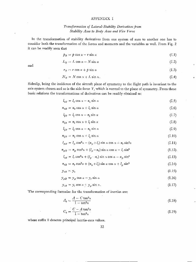
A P P E N D I X I
Transformation of Lateral-Stability Derivatives from Stability Axes to Body Axes and Vice Versa
I n t he t r a n s f o r m a t i o n of s t ab i l i t y der iva t ives f r o m one sy s t em of axes to ano the r one has to
cons ide r b o t h t he t r a n s f o r m a t i o n of the forces and m o m e n t s and the var iab les as well . F r o m Fig . 2
i t can be r ead i ly seen tha t
PB = p c o s ~ - r s i n a
L z = L c o s a - N s i n c ~ a n d
r B = r c o s ~ + p s i n
N B = N c o s c ~ + L s i n ~ .
(1.1)
(I.2)
(I.3)
(I.4)
Sides l ip , be ing the inc idence of t he a i rc ra f t p l ane of s y m m e t r y to the f l ight p a t h is invar ian t to t he
axis sy s t em chosen a n d so is the s ide force Y, w h i c h is n o r m a l to the p lane of s y m m e t r y . F r o m these
bas ic re la t ions t he t r a n s f o r m a t i o n s of der iva t ives can be r ead i ly o b t a i n e d as:
nvB =
~ =
l~B =
n~ B =
I . B =
n ~ B
rlrB
Y v B =
Ypl? =
YrB =
T h e c o r r e s p o n d i n g f o r m u l a e
A 0 ~-~
l v c o s c ~ - n v s l n o z
n~ cos a + l , s in
l g c o s o~ - ~/~ s i n (x
n e cos ~ + lg s m
l g c o s o~ - - ng s i n c~
ng c o s o~ + l~ s i n o~
l . cos2a - (n . + l,.) s in a cos a + n r sinS~
n2~ cosSa + ( l . - nr) s in c~ cos a - l r s in s
l r cosSa + ( l p - n~) sin a cos a - n~ sin ~
nr cosSa + ( n . + 1,.) sin c~ cos a + lp sin s
Y~
y . cos ~ - Yr sin
y,, cos ~ + y~, s in a .
for t h e t r a n s f o r m a t i o n of iner t ias are:
A - C tanSa
1 - tanS~
C - A tanSa C° = 1 - tan2~
w h e r e suffix 0 deno tes p r i nc ipa l ine r t i a -axes values .
32
(1.5)
(1.6)
(1.7)
(1.8)
(1.9)
(1.10)
(I.11)
(I.12)
(1.13)
(I.14)
(1.15)
(I.16)
(1.17)
(I .18)
(1.19)

F o r comple t enes s the inverse t r a n s f o r m a t i o n s f r o m b o d y axes to s t ab i l i ty axes are g iven be low:
1 v = lvB cos ~ + n~B sin ~ (1.20)
n, = nob cos ~ -- lob sin ~ (1.21)
l~ = l~B cos c~ + n~B sin ~ (I .22)
n~ = n~B cos ~ - l~B sin ~ (I .23)
= l;B cos + n,B sin (1.24)
n~ = n~B cos ~ - l~B sin a ( I .25)
l~, = l~, B cos2c~ + (lrB+n:oB) cos c~ sin c~ + nrB sin2a (1.26)
n~ = n~B cos%~ + (nrB - l~B ) cos c~ sin o~ -- l,. B sin2cx (I .27)
l~ = l~B cos2~ + (n~B -- lpB ) cos a sin a -- n:o B sin2c~ (1.28)
n~ = nrB cos%~ - (l,. B + n2,B) cos cx sin c~ + l~, B sin2c~ (1.29)
Yi, = Y~B cos c~ + y ~ sin o~ (I .30)
Y,. = Y~B cos o~ - Y~B sin o~. ( I .31)
Ine r t i a s in w i n d axes are o b t a i n e d f r o m p r i n c i p a l iner t ias b y
A = A 0 c o # ~ + C O s i n ~
C = C O cos~c~ + A 0 sin2~
E = (A 0 - C 0 ) s i n ~ c o s ~ .
(1.32) (1.33) (1.34)
A P P E N D I X I I
Transformation of Dutch-Roll Ratio from Body Axes to Wind Axes
T h e typ ica l la te ra l osc i l la t ion i l lus t r a t ed as a t ime h i s t o ry of p and r in F ig . 7 can be r e p r e s e n t e d
by a vec to r g r a p h s h o w i n g the m o d u l i of t he a m p l i t u d e in rol l and y a w in the i r p r o p e r phase
re la t ionsh ip .
U s i n g the t i m e - v e c t o r concep t t he axes t r a n s f o r m a t i o n s
pB(t) = p(t) cos ~ - r(t) sin ~ ( I I .1 )
rB(t ) = r(t) cos a + p(t) sin a (11.2)
can be n o w ca r r i ed ou t as a vec tor ia l s u m m a t i o n
f ib = ff cos ~ - f s in ~ (11.3) fB = ~ cos ~ + ff s in c~ (11.4)
w h e r e bars over a s y m b o l deno te t i m e vectors . T h i s p rocess is i l l u s t r a t ed for a typ ica l e x a m p l e
in F ig . 8. I n v i e w of t he no to r ious c o m p l e x i t y of p e r f o r m i n g th is o p e r a t i o n a lgebra ica l ly t he g r a ph i c
m e t h o d r e c o m m e n d s i t se l f ve ry forc ib ly . T h e d u t c h - r o l l ra t io in t he n e w s y s t e m is t h e n s i m p l y
o b t a i n e d b y d iv id ing the m o d u l i (magn i t udes ) of the r e su l t ing vectors , i.e.
pB If[ r B - i f ] ( I I . 5 )
33
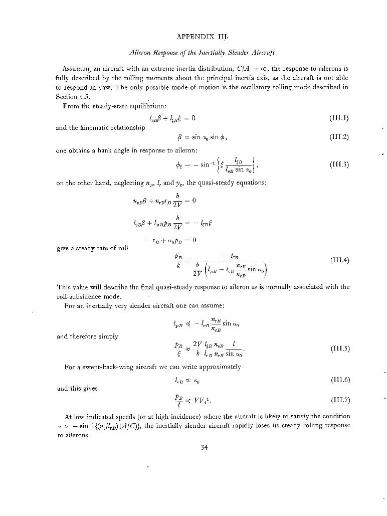
APPENDIX III,
Aileron Response of the Inertially Slender Aircraf t
Assuming an aircraft with an extreme inertia distribution, C / A -+ oo, the response to ailerons is fully described by the rolling moments about the principal inertia axis, as the aircraft is not able to respond in yaw. The only possible mode of motion is the oscillatory rolling mode described in
Section 4.5. From the steady-state equilibrium:
I~B5 + l~B~ = o ( I l i . 1 )
and the kinematic relationship /3 = sin % sin 6, (111.2)
one obtains a bank angle in response to aileron:
l I~B I (III.3) ¢~ = - s i n - 1 ~lvBsin% '
on the other hand, neglecting n~, l r and yv, the quasi-steady equations:
b nod3 + n~Br ~ ~ = 0
b l, oB5 + l~BPB 2 v - leB~
give a steady rate of roll - r B + % P B = 0
PB _ - ~B ( I I I . 4 ) b( _ ) 2 V l~)B -- l 'B nrB sin %
nvB
This value will describe the final quasi-steady response to aileron as is normally associated with the roll-subsidence mode.
For an inertially very slender aircraft one can assume:
and therefore simply
I,~B ~ _ lo B n,.~ sin % nvB
PB 2V l~B n~B l (Ili.5) ~- ~ b loB nrz sin %"
For a swept-back-wing aircraft we can write approximately
- lob oc % ( I I I . 6 )
and this gives
P B oc V V ¢ . (1II.7)
At low indicated speeds (or at high incidence) where the aircraft is likely to satisfy the condition c~ > - s i n - i { ( n ~ / l o B ) ( A / C ) } , the inertially slender aircraft rapidly loses its steady rolling response
to ailerons.
34
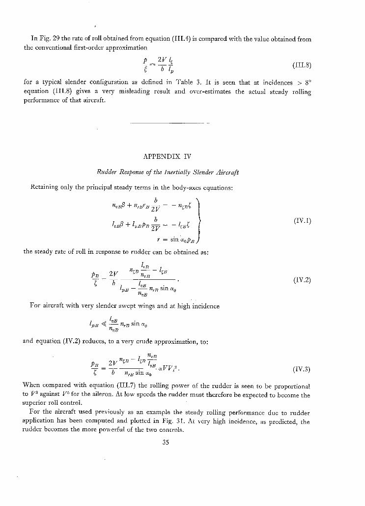
In Fig. 29 the rate of roll obtained from equation (1II.4) is compared with the value obtained from the conventional first-order approximation
p 2 V l~ b l~ (III.8)
for a typical slender configuration as defined in Table 3. It is seen that at incidences > 8 ° equation (111.8) gives a very misleading result and over-estimates the actual steady rolling performance of that aircraft.
APPENDIX IV
Rudder Response of the Inertially Slender Aircraf t
Retaining only the principal steady terms in the body-axes equations:
n~Bfi + n~BrB 2 V = n~B~
b l ,B5 + I BPB
r sin %PB
the steady rate Of roll in response to rudder can be obtained as:
PB 2V n B- nvB
I~B - n~B sin % 1%B
For aircraft with very slender swept wings and at high incidence
l~, B "~ n,. B sin ~0 n,,B
and equation (IV.2) reduces, to a very crude approximation, to:
(IV.1)
(IV.2)
PB _ 2 V n~B - I~B nvB l~B ~ V V ~. (IV.3)
b nrB sin %
When compared with equation (III.7) the rolling power of the rudder is seen to be proportional to V a against V 5 for the aileron. At low speeds the rudder must therefore be expected to become the superior roll control.
For the aircraft used previously as an example the steady rolling performance due to rudder application has been computed and plotted in Fig. 31. At very high incidence, as predicted, the rudder becomes the more powerful of the two controls.
35

TABLE la
The Coefficients of the Stability Quartic and the Stability Determinants for the Lateral Motion of the Aircraft in Stability Axes and in Principal Inertia Axes .for Level Flight
Ja
&
J1
Jo
Coefficients of the lateral stability quartic: M + JaA a + J2A 2 + J l h + Jo = 0
In stability axes
1 - j ~ - ge~ - ~ ~ - ~4/'~ - y~ E E
. . . . .
CA
In principal inertia axes
• i f 2 A i f2]
Yv 1 E
C A
1E E IYv(.Cp~r-~Ur~q~v)- CL ( ~ + ~ A / v E )
CA yp'
C~_L (~C~ - ~,7,.) 1 2 1 E E
C A
= - ~ e ~ - , Y ' ~
- Y d -Y g
E A~ .Azfi t _ A~
E A2
tze
- A / ~ - 5~'~,B - - Y ,
Y~(~vB+g/'"B) + ~V'~ ( 1 - y~]ff~ / -
- ~fvB (sin ao + Y~B]t,~ / + JUrB~'"B -- aV'vB=°~'rB
CL (L,~,.B +jff .B sin %) + y~( jV pBS~B -- g/'~B~ p B) -- ---f
+(~vB~C~e--dU~n~vB)( 1-y~B]ffz / +(~BdU~B--~q~BdV"~B)( sin%+yp~-B]tt 2 /
(~B~,V'rD--~.V'vBgfm) + sin % ~ -
t" fl J PB dt
jV" B JV'~) BA
CL ( + N,B] ~ y v _ A ~ - - + s i n a o - ~ 2 /
f ri¢ dt
JV'~B),- t 2
CL sin a o 2 i
- g / ~ - X ~ B ~
- ~ B ~ - ~ B ~
- y~: - y ~
(87541)
37

T A B L E lb
Definitions of Concise Derivatives used in the Stability Equations of Table la
Stabi l i ty axes Principal inertia axes
~A
~A
f~Cv = / L ~ = - ~A
Z A
Z.A
~f p np
2C
ny
tG
n v J V v = ~ 2 =
ZC
n~
~C
n~ "A/'~ = /~2 - -
ZG
l~oB ~2oB ~ 7
~AO
lrB ~ r B ~- 7
ZA o
[vB ~ v B = 1~2 7
ZAO
-Lf ~B = 1~2 7
1 C o°CP~B = I% ~AO
JJ/'pB -- I/IpB. ~CO
*/~rB -~ nrB. ZCO
nvB ~V'vB = I~a .
ICO
n~B. ~ C ~ B = 1~2 .
gCO
n~B ~/'~B = /~2 •
~CO
39
(8754]). D

TABLE 2
Approximate Formulae .for the Stability Parameters of Various Simplified Types of Lateral Oscillations
Type of oscillation
Pure directional
Lanchester oscillation
Classical dutch roll
Pure rolling about body axis
Rolling oscil- lation with lateral movement
I Assumptions
~b- - f i p = 0
Typical aircraft conditions
Conventional straight wing or swept wing at small incidence High aspect ratio
Period T sec
0-785V~. (b \ l ~ ]
16.08
22.75 r = O
A = 0
No rotary cross
derivatives No product
of inertia
r B = 0
rB -= 0
Conventional con- figuration with zero nv
lp >~ i~
Valid for most air- craft up to modest incidences
Slender Design A ~ C and swept
wing at high inci- dence %
As with pure body roiling, better ap- proximation of damping
see {TV,:}
Wavelength {TVD ft
d (bW/S]
/ { bW/S ~
As pure directional oscillation
see {TV,}
see { TV~}
16.08 / i - bW/S \
l,, in PI axis
[ - bW/S~ 16.08
&/ t sm % "~'7- I \ IdOl
Time to damp {q/~vDft
18.15 W/S
18.15 W/S %/o" Y v
n #
ic Yv Jr
1.63
18.15 W/S "v/~ l~B/i ~o
l . in PI axis
=
log. decrement 8
"r l i b : ] -0"614 i~ ~ l IW,!~_!
'~/ \ S i t /
-0"868y~ / { balp ~/ t WlSCd<,!
13.1 C&li<, (l,,li~)= + 26.2 w / s n,,
ba ico
b~ !
- 0" 614 1.z~ be Go W I~B
• - s i n c¢ o
S Z_4o
l~) and l~ in PI axis
- 0"614 l~B 0.307Cc 7 gAO sin. %
iA0 bcr s in%
Roll ratio 4/~
Zero by definition
n~ ~.,ndic] ,i e 1 + (1,/iA)2 ]
1 sin %
= fpBd t
1
sin a o
Terms considered
n~ n~ m = 5 + = ~ r - ~ -- 0
Zc, ~C
u2l~fi + lp~p = 0 c~
y 3 + ~ - 4 - ~9 = o
n~ m ~.~' f~ + = ~r - ~"~ = 0
~C ~C
~ + i s ~ p - ~ = o
c ~ y,$ + ~ - 4 - (9 + r)~ = o
lob lP B ^ ^2 " ~2 iA,--,13 + ~ tpB- t ~B = o
PB sin % = 9
lvB_ 5 {*'BpB~ A2" /L 2 . + -- t LPB = 0 ~A0 ZA0
~r- 4 ~ o + pB t sin a o - 9 ~ =
41 (87541)
D*

T A B L E 3
Geometric, Inertia and Aerodynamic Data used for the Aircraft as an Example in the Roll-Response Calculations
W/S = 401b/f t z lg = - 0 . 0 8 n~ = 0
b = 80 f t /~ = 0 .015 ng = - 0 . 0 5
A/C = 0 .1 1~ = ' - 0 . 1 0 n~ = 0
i o = 1 .0 l v = - 1 . 0 s i n ~ n v = 0 .15
i a = 0"1 n ~ = - 0 . 2 5
i~2 = 13.1 a = ~CL/3~ = 2 . 0 P . I . axis a l igned at ~ = 0
T A B L E 4
Approximate Formulae )'or the Roll-Response Parameters of the Conventional and of the Inertially Slender Aircraft
C o n f i g u r a t i o n
App l i e s for i nc idence range
S t e a d y ro l l ing due a i le ron
S t e a d y ro l l ing due to r u d d e r
R e s p o n s e t ime lag of rol l subs i dence
In i t i a l s t eady bank angle due to a i le ron
Response t i m e lag to r each ini t ia l s t eady bank
to p
P
t A s e c ) =
t 4 s e c ) =
C o n v e n t i o n a l a i rc raf t
n 0 A
_ _ m _
l~ n~/
1~, nv/
2 V n~ Iv n7 - l~
+
2 6 . 2 W/S i•
X
S le nde r a i rc ra f t
n v
2V ~B
lj, B - I~B n~n sin % nvB
lvB 2 V n~l~ ~,B l~B
b 11,~ ~ _ lv n n~__~ s in %
nvB
- sin-Z @ l~ sin 402/( V,: • l , ~ /
sln e~ o 7 1 ~'A 0 /
43

LB~PB (/~
N~'t"
FIG. 1. Definition of the stability axes system and the body (principal inertia axes) system in the aircraft.
Na (~%)
FIG. 2. Moments and rates of rotation in stability axes (no suffix) and body axes (suffix
B). Only positive quantities are shown.
44

(~) A~P,C.RAFT INITIALLY ' DISTURB.ED IN 8 A N R
PLAN VIEW
. / f J
f/---'/ /', q ~ - ..¢. I • , ~ ] £ 51NCE .'T "-- /~ . - 'T - -
FIG. 3. Spiral motion of the aircraft in plan view.
or. = cko'= CONSI".
/3 ~ coN51" .
g,g,TE OF i~OLL
FIO. 4. Rolling about the stability axis.
SIDE VIEW
PLAN VIEW
45
( 8 7 5 4 1 )
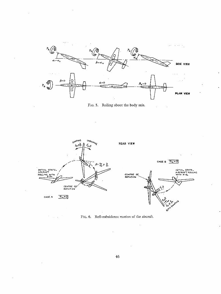
PB
, . , . J
~ PLAN VIEW
FIG. 5. Rolling about the body axis.
b ~ pi v
f f
f INITIAL STATE, /
;1?~;~WiTH /
CENTRE !~OTATION
cAs~" A ._~p~O I
REAR VIEW
CENTRE OF ROTATION
c a r " B ~p<o I
INITIAL STATE, AIRCRAFT ROLLIN~ WrTH P=Po
FIG. 6. Roll-subsidence motion of the aircraft.
46

i Kt~PoPo Pemoo " ~"
OF" L A T E R A L P U 4 ~ [ ~ O S C I L L A T I O N
",~ I ~ " ~
• I I
I 7 T~H~ DELAY O~ F ROL),,. A G A I N S T YAW
DUTCH-~Okk. RATIO ~ . - g : . ~)" PHASE: L A G O~ R O L L A G A I N S T YAW ~ = 3 6 0 ° ~ P
0~:10 e
-¢s
0( = 2 0 °
¢
FIG. 7. tion and definition of dutch-roll ratio.
(a) As a time history.
(b) As represented by time vectors.
p ~
P AX~'S IN THE ~ F'T
STABmITY ' ~ I A~ ~ + Ax,s / II I ~ T , " /
/ 11 I / , + /
~,;4" I JO/f~ ~ 0 + ] / ~ E Y 160 o
5 ° 0 ° S o i 0 ° 15 ° 2 0 ° e~ 25 °
Time history of a typical lateral oscilla- FIG. 8. Change of dutch-roll ratiop/r with incidence of reference system with respect to stability axes.
,'3
0 5o i 0 ° 15o . 2 0 o 2 5 ° 0<.
FIG. 9. Change of the ratio of fp dt/13 with incidence of reference system for p.
47 (87541) D** 2
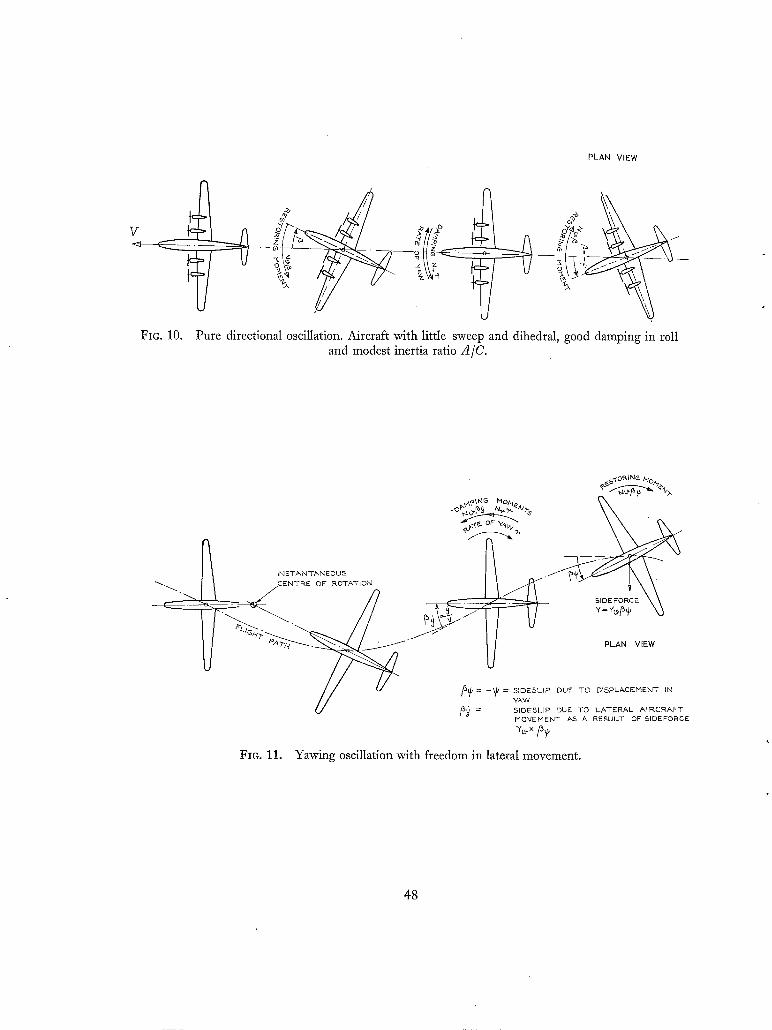
PLAN VIEW
v "~--- Q_~-
FIG. 10.
- ~ • o ~ _ _ ~
Pure directional oscillation. Aircraft with little sweep and dihedral, good damping in roll and modest inertia ratio A/C.
INSTANTANEOUS < N T R E OF ROTATION]
FIG. 11.
s~ "~°~N~ "-;o/,7
\ \
SIDEFORCE
3~, = _~] = 51DESLIP DUE TO DISPLACEMENT IM YAW
/&~ = SIDESLIP DUE TO LATERAL AIRCRAFT MO'qEMENT AS A RESULT OF SIDEFORCE
Yawing oscillation with freedom in lateral movement.
4 8

FIo. 12. 'Lanchester' oscillation. Freedom in roll and lateral movement. (nv/ie) - , O, - l ; >~ ix.
t~PHd~ O, P. ~ N ~
~/ /~ '~A~ ~ ~ . / ~ "
FIO. 13. Conventional dutch roll. Aircraft with good damping in roll (large aspect ratio) and modest inertia ratio A/C. Aircraft rotations in stability axes.
49
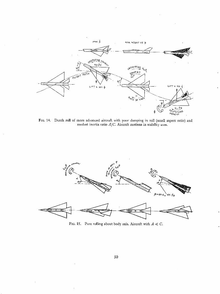
MAX MAX. N~'GATI V E
- - . . . . . - ~ o - - - ~/ . _ r - ~
t V A ,<v -,,-_~h~ x.~ .~-SroR~ G
ta/OM E N T
Fie. 14. Dutch roll of more advanced aircraft with poor damping in roll (small aspect ratio) and modest inertia ratio A/C. Aircraft motions in stability axes.
Oor4e'¢, - o~,~,
FIo. 15. Pure rolling about body axis. Aircraft with A < C.
50

' ,J'l
0"1
1%.~.-
-O '1
- 0 ' ~
0 " 2
7"l o
O'1
"~ 13. BODY "----
-O'1
- 0 2
-0"3
-O.~"
- / ~ o a ° ° ~ / -
5 ° 10 ° 15 ° 2 0 ~
f
\ , \ \
\
FIG. 16. n o and l~ referred to stability axes and body axes for
two delta-aircraft configurations.
+ 0 . 0 5
- 0 . 0 5
-0'.1
~ 2 " - --' ~--
0.1~
~-0~
- @ 0 5
l [
I
FIo. 17. Yawing moment due to rate of roll np in stability axes and body axes for two delta aircraft.
01930 1 9 4 0 19SO 1960 1970
FIG. 18. Inertia distributions of typical fighter aircraft.
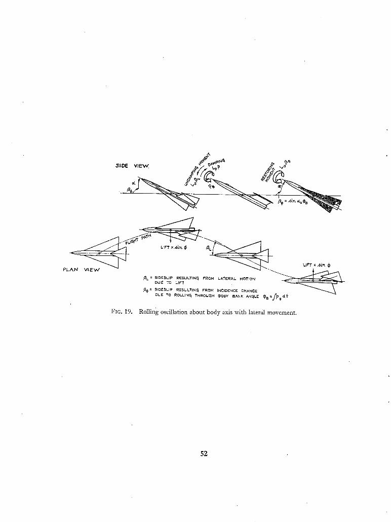
• ~-+ t , , . , '~ ' o,.o:+?,,,.~>
FIG. 19.
/31. = SIOESLIP RESULTIN~ FROM LATERAL MOTION . OUE TO LIFT . ~
13(~ = SlOESLll ~ IRESULTIN~ FROM INCIDENCE CHANGE DLJE TO ROLLIN~ THROUGH 60DY ~ANK AN~LE ~8=fpBaf
Rolling oscillation about body axis with lateral movement.
52

ISOC
Iooo
WAVELEN~iTH T,V~ Err]
5OO
o
I0 DUTCH-ROLL
RATIO (¢1~)
5
o
~'0
DAMIDING 8
I 'O
O
"-¢?
\
o.5 CL I.o
O.S CL I'O
COR~'C ~LLU~- P~-~...
~ o , ~
04/.~ ....
O.S CL 1.0
Fro. 20. Comparison of the sta- bility parameters of the lateral oscillation of a swept-wing aircraft with the approximations based on the classical dutch-roll concept and
the rolling mode respectively.
~ooo \
1500
WAVELENGTH T~Vl. [FT]
looo
"XDIR=_ cr l O_N_A_L_ _o~
¢ O
• -~CI LLATIO 1
0"5 I'0 C L
] LAfJO-;~'--'-
o O.B CL .0
ibO
DAMPIN~ 8
+1 "0
- I , O
,,~ ,>Y
\~' o¢-~ / I .I \ ° s c i ~3" I i i %x>. ,~, , , . '" .q ~r'°-z~s ' r "%hi
"-, 0,5 CL
< i
FIG. 21. Comparison of the sta- bility parameters of the lateral oscillation of a delta-wing aircraft with the api~roximations based on the classical dutch-roll concept and
the rolling mode respectively.
--==-9
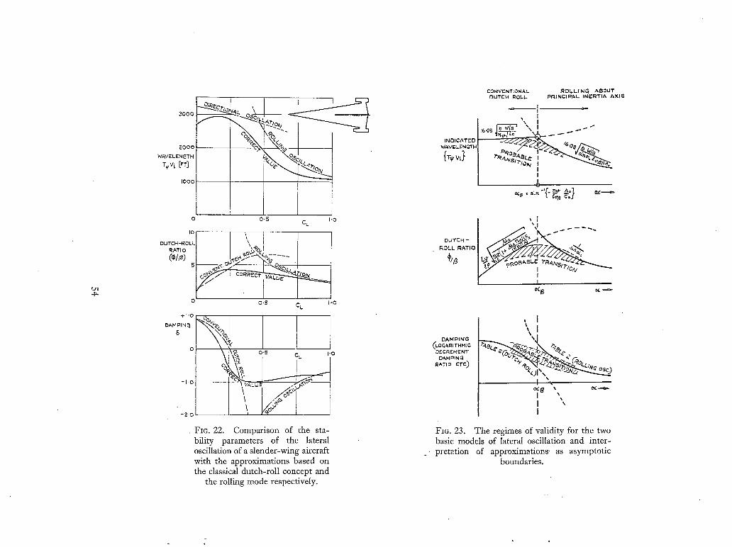
UI 4~
/-- " ?,s"
IOOO
0 0.~ I'0 CL
DUTCH-ROlL: \''0 RATIO I I _ ~ .%£. {<~ , , ; . . . .
(°/~> , t - - ; . / ; " ? % I
O O~ CL I '0
el'O CO
o , ~ o.~ c~ ~-o ~2- I ,
t
-"° I lJ~ -~-O
F~o. 22. Comparison of the sta- bility parameters of the lateral oscillation of a slender-wing aircraft with the approximations based on the classical dutch-roll concept and
the rolling mode respectively.
2OOO
WAVELENGTH
INDICATED WAVEL.ENGTN
by,}
CONVENTIONAL ROI.LI NG ABOUT DUTCH R O L L PPdNCI~AL INERTIA AXIS
I I
"~-"~.<A'd~ '~.o~
I
ROLL RATIO ~//3 ~ ° - ' ' ""°
g
DAMPING LOGAI~I rH HIC De'CREHENT"
DAHI~IN~ RATIo eTC)
, I
t a
i
FIG. 23. The regimes of validity for the two basic models of lateral oscillation and inter-
p r e t a t i on of approximations as asymptotic boundaries.

EXAMPLE
EXAHPLE
/WAVE-LENGTH IDUTEH~ROL~._
k c~ I ~ Osc.
O( C¢
LENGTH I
BASIC CONFIGURATION R E D u C E D ~ . u -
Fm. 24. Effects of changes in aerodynamic derivatives on the stability of the lateral oscillation.
' o~ o( c4 c<
x ~ x
t _ _ _ _ _ g _
B' DATING
BRSIC CONFIGURATION INCR~SED A ING ~RE/:~SED C INCRENS~'D W/S
o~
~-D~CED INC.I D~.H C E OF P.T. AXIS
FIo. 25. Effects of changes in aircraft loading on the stability of the lateral oscillation.
55

Grl
t
C~NVENTIONAL AIKCRAFT
RATE CONTF~OL
/ t
LOW P~PECT RATIO A/C
ACCELERATION CONT~O~
" D
t
INKI~fl,'~,.LY ~,LENDE'.R /~C
POSITION CONTROL
FIG. 26. Response in roll of three basic aircraft configura- tions to sudden aileron application at t = 0.
1 8 0 ° -
155 °
BANK
@5*
J O
f
FZG. 27. Response in roll of an inertially infinitely slender aircraft to various amounts of aileron applied instantaneously at t = 0 (aileron is increased by equal increments).
BANK AN~LK
z / . ~ _ ' C I L I A T I O N
t p t
I~OLL-SUBSIOEN CE TIME LAG,
FIG. 28. Response in roll of a practical inertially slender aircraft to an aileron step
input.
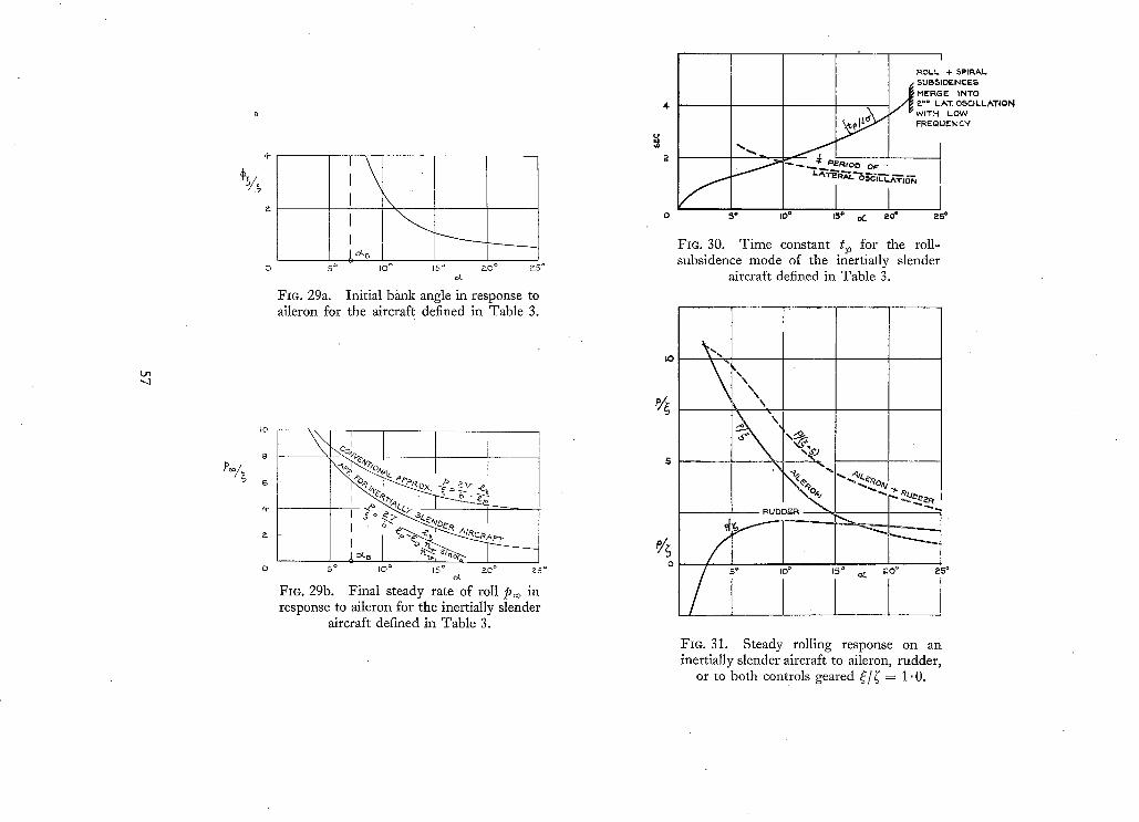
L r l , q
't- 1 , \ I J I j,o%
I 0
8
' t-
0 5 ° I O °
\
15 ° & O ° K5 °
Fie. 29a. Initial bank angle in response to aileron for the aircraft defined in Table 3.
I X ~.'~ ~sI.~iVD ~ I
S ° iO ~ 15 ° 2~0 ° ~5 ° d .
Fie. 29b. Final steady rate of roll P~o in response to aileron for the inertially slender
aircraft defined in Table 3.
4
2
IO
0
f
ROLL + SPIRAL
A SUB~IDENCIEE) PIEFtG E INTO ~-'= LAT. O ~ C I L L A T I O N WITH LOW FREQ JCY
2>-<,. " ~ ' ~ P£RIOD OF" "
I I0= 15° OC 20~ 250
FIG. 30. Time constant t~ for the roll- subsidence mode of the inertially slender
aircraft defined in Table 3.
\ N
% RUDDER ~ ,
5 o IO ° F.O ° 15 ° ~
FIG. 31. Steady roiling response on an inertially slender aircraft to aileron, rudder,
or to both controls geared ~:/~ = 1.0.

l i / / [ PURE RLJDD¢"I~ i "" "F I I U P P E R CONTI~O k. ~ "I R U D D E R
I L.OWER
PURK L ATF-I~AI- ........... J--
CONTROL,. ( --~ o (TURN E N T R" / ) --~ ~ - 1 ~ ' 1
C ~ - ~ J - - " ~ I I, S T A . R B O A R D ~ ~ ~ _ I A I L E R O N
C O N T R O 1 ~ - ~ I ~91 l
°~,~ -%. ~ I , q U S T OR " N ~ / \ I L . _ / I I
__o# ~ I I
~ I I ~ L I
FIG. 32. Coupled lateral-control layout for improved roll response of inertially slender aircraft.
4 . 0 - -
,3.0
m_~ ,>;.~
~ 0
I ,O
i I I
A ~ = I N C R E M E N T A l - INCIDENCE.. O(o = T R I M I N C / D E N C G IN
LEVEL FLI~biT
' ,~Si'_--v¢<~ ~'°~ ~-7
20 ° 40" 60"
BAMK ANG~LF- ¢
.9
/
=L - I c°sp l
80 °
FIG. 33. Incremental incidence Aa required for turn co-ordination after the completion of a pure bank
manoeuvre.
58

60o~ u~ x
I0
-4- 6 8 Io
acL/a~
FIG. 34. Equil ibr ium bank angle in response to a side gust va a of an inertially slender aircraft. Valid if % > sin -1 { ( - n~llv) (a/C)}.
6 0 ° 4¢] ~ --- .,
0 1
.,%o! \
I 3 4. 5F'C
FIG. 35. Approximate response in bank of the aircraft defined in Table 3 to a 20 ft/sec
sharp-edged side gust.
(87541) Wt , 64/1857 I ( .5 9/63 H w .
59

Pubiications of the Aeronautical Research Council
194z Vol. Vol.
1943 Vol. Vol.
1944 VoI. Vol.
1945 Vol. Vol. Vol.
Vol.
1946 Vo!. Vol.
Vo!.
1947 Vol. Vol.
A N N U A L T E C H N I C A L R E P O R T S O F T H E A E R O N A U T I C A L
R E S E A R C H C O U N C I L ( B O U N D V O L U M E S )
I. Aero and Hydrodynamics, Aerofoils, Airscrews, Engines. 75s. (post as. 9d.) II. Noise, Parachutes, Stability and Control, Structures, Vibration, Wind Tunnels. 47~. 6d. (post 2s. 3d.)
I. Aerodynamics, Aerofoils, Airscrews. 8os. (post as. 6d.) II. Engines, Flutter, Materials, Parachutes, Pe1:formance, Stability arid Control, Structures.
9os. (post as. 9d.) I. Aero and Hydrodynamics, Aerofoils, A!rcraft, Airscrews, Controls. 84s. (post 3s.)
II. Flutter and Vibration, Materials, Miscellaneous, Navigation, Parachutes, Performance, Plates and Panels, Stability, Structures, Test Equipment, Wind Tunnels. 84 s. (post 3s.)
I. Aero and Hydrodynamics, Aerofoils. I3OS. (post 3 s. 6d.) iI. Aircraft, Airscrews, Controls. I3OS. (post 3s. 6d.)
III. Flutter and Vibration, Instruments, Miscellaneous, Parachutes, Plates and Panels, Propulsion. 13os. (post 3s. 3d-)
IV. Stability, Structures, Wind Tunnels, Wind Tunnel Technique. I3os. (post 3s. 3d.)
L Accidents, Aerodynamics, Aerofoils and Hydrofoils. I68S. (post 3s. 9d.) !I. Airscrews, Cabin Cooling, Chemical Hazards, Controls, Flames, Flutter, Helicopters, Instruments and
Instrumentation, Interference, Jets, Miscellaneous, Parachutes. i68s. (post 3s. 3d.) III. Performance, Propulsion, Seaplanes, Stability, Structures, Wind Tunnels. i68s. (post 3s. 6d.)
I. Aerodynamics, Aerofoils, Aircraft. 168s. (post 3s. 9d.) II. Airscrews and Rotors, Controls, Flutter, Materials, Miscellaneous, Parachutes, Propulsion, Seaplanes,
Stability, Structures, Take-off and Landing. i68s. (post 3s. 9d.)
1948 Vol. I. Aerodynamics, Aerofoils, Aircraft, Airscrews, Controls, Flutter and Vibration, Helicopters, Instruments, Propulsion, Seaplane, Stability, Structures, Wind Tunnels. I3OS. (post 3s. 3d.)
Vol. II. Aerodynamics, Aerofoils, Aircraft, Airscrews, Controls, Flutter and Vibration, Helicopters, Instruments, Propulsion, Seaplane, Stability, Structures, Wind Tunnels. XlOS. (post 3s. 3d.)
Special Volumes VoL I. Aero and Hydrodynamics, Aerofoils, Controls, Flutter, Kites, Parachutes, Performance, Propulsion,
Stability. i26s. (post 3s.) Vol. II. Aero and Hydrodynamics, Aerofoils, Airscrews, Controls, Flutter, Materials, Miscellaneous, Parachutes,
Propulsion, Stability, Structures. i47 s. (post 3s.) Vol. III. Aero and Hydrodynamics, Aerofoils, Airserews, Controls, Flutter, Kites, Miscellaneous, Parachutes,
Propulsion, Seaplanes, Stability, Structures, Test Equipment. 189s. (POSt 3s. 9d.)
Reviews of the Aeronautical Research Council I939-48 3s. (post 6d.) 1949-54 5s. (post 5d.)
Index to all Reports and Memoranda published in the Annual Technical Reports 19o9-1947 R. & M. z6oo (out of print)
Indexes to the Reports and Memoranda of the Aeronautical Research Council Between Nos. 2351-2449 R. & M. No. 2450 as. (post 3d.) Between Nos. 2451-2549 R. & M. Between Nos. 2551-2649 R. & M. Between Nos. 2651-2749 R. & M. Between Nos. 2751-2849 R. & M. Between Nos. 2851-2949 1~. & M. Between Nos. 2951-3o49 R. & M. Between Nos. 3o51-3149 R. & M.
No. 255 ° as. 6d. (post 3d.) No. 265o as. 6d. (post 3d.) No. 275 o as. 6d. (post 3d.) No. 2850 as. 6d. (post 3d.) No. z95 o 3s. (post 3d.) No. 3o5 o 3s. 6d. (post 3d.) No. 315o 3s. 6d. (post 3d.)
HER MAJESTY'S S T A T I O N E R Y OFFICE from the addresses overleaf
:.. ,!
R. & M. No, 3334
© Crown copyright I963
Primed and published by HER MAJESTY'S STATIONERY OFFICE
To be purchased from York House, Kingsway, London w.c.2
423 Oxford Street, London w.I I3A Castle Street, Edinburgh 2
Io9 St. Mary Street, Cardiff 39 King Street, Manchester z
5 ° Fair£ax Street, Bristol x 35 Smallbrook, Ringway , Birmingham 5
80 Chichester Street, Belfast I or through any bookseller
Printed in England
R° & Mo Noo 3334
S.O. Code No. 23-3334


![Quadriwave lateral shearing interferometry for ...€¦ · shifting methods to DIC to acquire linear phase gradient images [3] [4] [5]. In particular, a method combining phase shifting,](https://img.pdfslide.us/doc/110x75/5fe13e4af425ca153a557955/quadriwave-lateral-shearing-interferometry-for-shifting-methods-to-dic-to-acquire.jpg)