Embed Size (px)
Citation preview
1
ISSUE 87 WINTER 2018THE LASER USER
IN THIS ISSUE:
THE
LASER USER
OPTICAL INNOVATIONIN MIRRORS & LENSES: SHAPING BEAMS FOR PRECISION MANUFACTURING
ISSUE 87 WINTER 2018
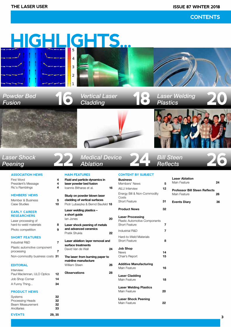
Powder Bed Fusion
Vertical Laser Cladding
Laser Welding Plastics
Laser Shock Peening
Medical Device Ablation
Bill Steen Reflects
2
ISSUE 87 WINTER 2018 THE LASER USER
THE LASER USER
Editor: Dave MacLellanSub-Editor: Catherine Rose
ISSN 1755-5140
© 2018 – Association of Industrial Laser Users
The Laser User is the house magazine of the Association of Industrial Laser Users. Its primary aim is to disseminate technical information and to present the views of its members. The views and opinions expressed in this magazine belong to the authors and do not necessarily reflect those of AILU.
The Editor reserves the right to edit any submissions for space and other considerations.
Authors retain the right to extract, in part or in whole, their material for future use. The Laser User is published quarterly in February, May, August and November by AILU for its members and is available in print or online.
Editorial Board for this issue:
Ric Allott STFCRavi Aswathanarayanaswamy RenishawPaul Goodwin TWILin Li University of ManchesterJames McDowell Litron LasersJonathan Magee Coherent | RofinMark Millar Essex LaserAndy Toms TLM Laser
Association of Industrial Laser UsersOxford House 100 Ock StreetAbingdon OxfordshireOX14 5DH
Tel: +44 (0) 1235 539595E-mail: [email protected]: www.ailu.org.uk
AILU STEERING COMMITTEE 2017-18
President: Lin Li (University of Manchester)Vice President: Jon Blackburn (TWI) Exec. Director: Dave MacLellan (Anode Marketing)
Elected until 2020Shireen Khanum (GF Machining)Anke Lohmann (Anchored In Ltd)Vojtech Olle (OSI Optoelectronics)Mike Poulter (SPI Lasers)
Elected until 2019Duncan Hand (Heriot-Watt University) Louise Jones (KTN)Jonathan Lawrence (Coventry University) Ian White (Yamazaki Mazak)
Elected until 2018Paul Goodwin (TWI)Roger Hardacre (ALT)Tony Jones (Cyan Tec Systems)Adrian Norton (thinklaser)
Co-optedAdam Clare (University of Nottingham)Mark Millar (Essex Laser)Stan Wilford (IPG Photonics)
Past presidents and founder members are also able to attend committee meetings. Anyone wishing to join the AILU Steering Committee please contact the Executive Director.
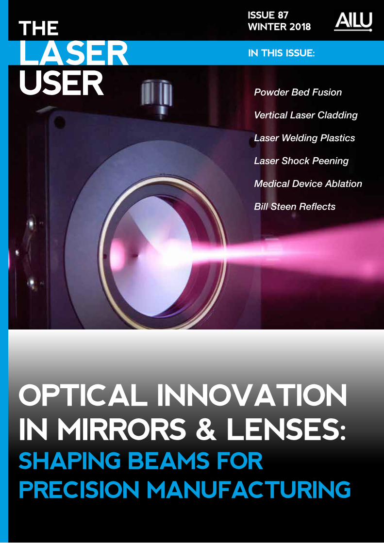
Cover image: An axicon lens (with a conical surface) is used to generate Bessel beams for femtosecond laser micromachining of glass and other materials.
Image courtesy of Rémi Meyer , FEMTO-ST Institute, Besançon, France.
WELCOME TO NEW AILU MEMBERS
ES PrecisionAndrew May [email protected]
LumentumPhilippe [email protected]
NKT PhotonicsPaul [email protected]
Proform Laser ServicesLaura Canner [email protected]
ADVERTISING ENQUIRIES+44 (0) 1235 [email protected]
Advertising rates at:http://bit.ly/AILU_MEDIA_GUIDE_2018
3
ISSUE 87 WINTER 2018THE LASER USER
CONTENTS
HIGHLIGHTS...
ASSOCIATION NEWS
First Word 4 President’s Message 4Ric's Ramblings 4 MEMBERS’ NEWS
Member & Business 5Case Studies 10
EARLY CAREER RESEARCHERS
Laser processing of hard-to-weld materials 8
Photo competition 9
SHORT FEATURES
Industrial R&D 7
Plastic automotive component processing 7
Non-commodity business costs 31
EDITORIAL
Interview: Paul Maclennan, ULO Optics 12
Job Shop Corner 14
A Funny Thing... 34
PRODUCT NEWS
Systems 32Processing Heads 32Beam Measurement 32Ancillaries 33
EVENTS 29, 35
MAIN FEATURES
Fluid and particle dynamics in laser powder bed fusionIoannis Bitharas et al. 16
Study on powder blown laser cladding of vertical surfaces Piotr Lubaszka & Bernd Baufeld 18
Laser welding plastics – a short guide Ian Jones 20
Laser shock peening of metals and advanced ceramics Pratik Shukla 22
Laser ablation: layer removal and surface treatments David Van de Wall 24
The laser: from burning paper to mainline manufactureWilliam Steen 26 Observations 28
CONTENT BY SUBJECT
BusinessMembers' News 5
AILU Interview 12
Energy Bill & Non-Commodity Costs Short Feature 31 Product News 32
Laser ProcessingPlastic Automotive Components Short Feature 7
Industrial R&D 7
Hard-to-Weld Materials Short Feature 8 Job Shop News 14Chair’s Report 15 Additive ManufacturingMain Feature 16
Laser CladdingMain Feature 18
Laser Welding PlasticsMain Feature 20
Laser Shock Peening Main Feature 22
Laser Ablation Main Feature 24
Professor Bill Steen Reflects Main Feature 26
Events Diary 36
26
20
24
18
22
16Powder Bed Fusion
Laser Shock Peening
Vertical Laser Cladding
Medical Device Ablation
Laser Welding Plastics
Bill Steen Reflects
4
ISSUE 87 WINTER 2018 THE LASER USER
FIRST WORDThe last couple of months have seen a ramp up of activity in the AILU office for our next 3 events which I hope that all of our members will get involved with.
Over the last two years (and more) a team of people and a number of working groups have pulled together a national strategy for laser material processing and the report “Lasers for Productivity: A UK Strategy”, outlining the recommendations, is to be launched at the Houses of Parliament on 6 March at 2.30pm. We are hoping to see 100 AILU members there and as many MPs as we can get to call in during the afternoon to meet their constituents and familiarise themselves with the capabilities of the laser in manufacturing. If you are interested to find out more, you can register your interest in the events pages on the AILU website (there is a link to Eventbrite on that page and registration is free). We are also looking for a good cross-section of samples to display on the day – showing some typical examples from manufacturing to highlight where lasers can be used.
MACH 2018 takes place on 9-13 April and there will be a Lasers for Manufacturing Zone, in place of the AILU Pavilion we have had in previous shows. Come along during the week or join us in the Zone as exhibitors.
Finally, we are getting closer to LPM 2018 (that’s Laser Precision Microfabrication in case you hadn’t heard) which gives our members a unique opportunity to visit this Symposium in Edinburgh from 25-28 June. Why not submit an abstract before it is too late? Registration is open, so register this week and get your accommodation booked! Those companies looking to sell into this market should also consider sponsorship and exhibiting opportunities. This event is more international than ILAS, so we expect a significant number of attendees from Japan, China, USA, Lithuania… I am hoping for a significant turnout – even more than the 220 we had at ILAS 2017.
Dave MacLellan AILU Executive Director
[email protected] 07473 121142
ASSOCIATION NEWS
PRESIDENT'S MESSAGE In this issue we have the honour of publishing an article by Professor Bill Steen (p. 26-27) outlining the history of laser processing in his research groups from the 1970s to the 2000s. Some of the photos in the article are published for the first time. The article is extracted from a longer document which I'm sure Bill would be happy to share if you interested - please contact him via the AILU office.
Reading this article brought me back to the 1980s and 1990s. I joined Bill’s laser group at Imperial College London in 1985 as a PhD student working on intelligent adaptive control of the laser cladding process. The project involved the closed loop control of laser power, powder flow-rate, clad deposition height and dilution using a hierarchical, multiple sensor and multiple loop structure combined with artificial intelligence (AI).
In 1988 I followed Bill to Liverpool University, working as a research assistant and later research fellow in a number of projects, including monitoring of high speed laser welding for industrial packaging and laser based nuclear decommissioning, until 1994 when I joined UMIST (University of Manchester Institute of Science and Technology) as a lecturer.
The 9 years of studying and working life with Bill laid down a solid foundation on which to build my entire career in the area of laser engineering. Bill was a most inspiring teacher, supervisor and a friend. He always inspired and encouraged students and researchers and gave them the opportunities and freedom to solve challenging scientific and engineering problems. Everyone was happier after talking to Bill in technical discussions.
Students and researchers were often invited to Bill’s house and annual barn dances were held for the laser group members and friends. He regularly sent PhD students and post-docs to various conferences to learn and interact with wider laser communities.
Bill received the Arthur Schawlow Award from the Laser Institute of America in 1996 and the prestigious Honorary Fellow of the Institution of Mechanical Engineers in 2017. We congratulate Professor Steen on his lifetime achievements that have changed the manufacturing world.
RIC'S RAMBLINGSDear Readers, for this latest edition of The Laser User my ramblings have taken me much further afield than usual. I write to you from SPIE Photonics West in San Francisco – a big old US style celebration of all things photonic. I have been coming to Photonics West for quite a while now (though not every year) and it never fails to impress me; the sheer number and range of companies exhibiting and the myriad of applications of “light” almost too numerous to list.
My story starts at the US border, standing in the seemingly never-ending queue waiting to show my passport and mentally preparing for the forthcoming rapid-fire inquisition as to why I feel I have the right to enter the country. The first part went fine – name, hotel etc. then the heat got turned up, “Why are you here?” oh I’m attending Photonics West, “What’s that?” it’s a big science conference on lasers and optics and stuff, “What do you do?” well I’m in business development, “business – what on earth has that got to do with science!? What can you possibly get out of attending that?”… well that stopped me in my tracks for a few seconds, my mind racing, my hands beginning to sweat at the thought of a small room and the unmistakable sound of marigold gloves being put onto large clumsy hands. Then I hit it – it's all about the applications – the science feeds the applications and that generates business
and we all benefit as a society from it –“oh ok, sounds cool, on you go Sir”. Phew I thought, that was a close one. But on reflection that is what Photonics West is all about - and from what I can see this week there is a whole load of business being done.
One of the most interesting sessions I attended was a panel discussion on taking Quantum Technologies into industry. Lots of opportunities in security, communications, next generation computing and so on, but whenever the panel experts specified where an application will be realised they were not able to say when with any certainty at all – good old Heisenberg must have been looking down and chuckling to himself. I think a whole load of wave-functions will need to collapse before we see Quantum fully integrated in our everyday lives, but it is coming and lasers have a big role to play.
I thoroughly recommend a trip to Photonics West – it makes you glad you chose photons as your choice of career, and if nothing else you get to eat lunch under blue skies and 20oC at the back end of January. What’s not to like?
Ric Allott [email protected]
5
ISSUE 87 WINTER 2018THE LASER USER
MEMBER AND BUSINESS NEWS
SPI LASERS APPOINTS NEW CEOSPI Lasers has announced the appointment of its CTO Dr Mark Greenwood to the position of CEO effective 1st January 2018, succeeding Dr Thomas Fehn who is moving to take up a position at SPI’s parent company, TRUMPF.
Mark has a long track record in the laser industry gained over 20 years in developing lasers for a wide range of applications and industries. He joined SPI Lasers in 2015 as part of the acquisition of JK Lasers where he was responsible for establishing the fibre laser technology base and product portfolio.
Contact: Matt [email protected]
MTC TO LEAD £14M AM AEROSPACE PROJECTFollowing the launch of the Industrial Strategy white paper on 27 November 2017, Business Secretary Greg Clark announced £53.7 million of funding for seven R&D projects.
One of those seven projects is The DRAMA (Digital Reconfigurable Additive Manufacturing facilities for Aerospace) led by the Manufacturing Technology Centre (MTC) with partners ATS Global, Autodesk, Granta Design, Midlands Aerospace Alliance, National Physics Laboratory, Renishaw and the University of Birmingham.
The project will showcase the use of digital technologies to drive productivity and reliability in AM, leading to increased adoption of AM technologies by the aerospace sector and, in the long term, other industrial sectors. It will also deliver the world’s first digitally-twinned reconfigurable AM facility and establish the UK as a global leader in AM technology.
The project, part of the ATI programme, has received a grant of £11.2 million through the Industrial Strategy Challenge Fund.
Contact: Kevin [email protected]
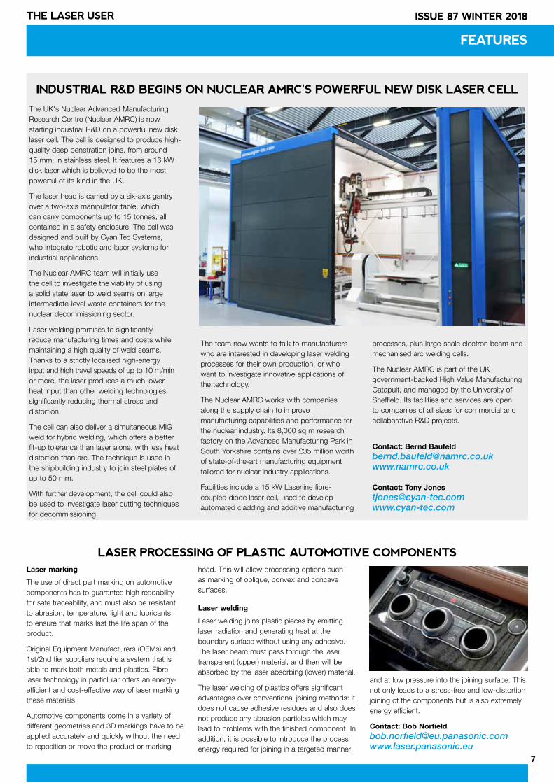
WORK STARTS ON NEW COHERENT PREMISESWork is under way at a Daventry business park to construct a new £2.3m purpose-built UK sales and service headquarters for Coherent | Rofin. Following site clearance work in December, foundations have been laid for the new premises, which is expected to be completed later this year.
Contact: Alan [email protected] www.coherent.com
Groundbreaking: L-R Daventry District Councillor Colin Poole; Alan Knape (Financial Controller) and Allan Hardisty (Head of Service for UK & Ireland), both of Coherent | Rofin.
RIC ALLOTT BECOMES VISITING PROFESSORAILU ex-President Ric Allott has been appointed Visiting Professor in the Faculty of Engineering, Environment and Computing at Coventry University. This follows on from a number of years working closely with Coventry on applications of high power lasers, such as laser peening and surface modification techniques and is in recognition of Ric’s academic and industrial contribution to lasers and photonics over his career.
Ric said “Being appointed visiting professor is a real honour for me and it will be an ideal platform from which to build on our collaborations with Coventry University and the broader community".
Contact: Ric Allott [email protected]
BILL STEEN INDUCTED AS HONORARY FELLOWWe are delighted to share the news that on 1st November 2017 Professor William Steen was inducted as an Honorary Fellow of the Institution of Mechanical Engineers. Bill founded the world’s first laser materials processing research group at Imperial College in 1968 and pioneered scientific research in this area.
This developed into a major manufacturing field including laser cutting, drilling, welding, surface hardening, surface cladding, material surface modification and additive manufacturing.
Bill is commonly referred to as the ‘Father of Laser Materials Processing’ within the laser processing community. He co-founded AILU and was its president for the first eight years.
Bill has documented his career leading research groups at Imperial College and later the University of Liverpool, a summarised version of which can be found on pages 24 and 25 of this magazine issue.
For further information visit http://www.imeche.org/news/
Bill Steen being presented with his Honorary Fellowship by Institution President Carolyn Griffiths.
ES PRECISION: NEW START-UP COMPANYIn October 2017, ES Precision opened its doors to offer laser processing to industries such as medical device, Formula 1, aerospace, electronics and general engineering. Business has started well and the 6 staff have been busy running jobs on the 8 laser workstations in their Oxfordshire premises. ES Precision is able to drill and cut organic materials at very high speed, mark label data onto any shape label and mark virtually all materials including all metals, most plastics as well as coated materials.
Contact: Andrew [email protected]
6
ISSUE 87 WINTER 2018 THE LASER USER
NEWS FROM TLM LASER
Partnership agreement
TLM Laser has further enhanced its laser products and systems portfolio through a partnership agreement with LasX Industries, producers of high performance production class laser converting systems and services.
Under this new partnership, TLM Laser will be responsible for the sales, marketing, installation and servicing of LasX Industries laser systems throughout the United Kingdom and Ireland.
New laser converting system
TLM's portfolio has been enhanced with the addition of LaserSharp® digital converting technology. The comprehensive laser processing systems developed by LasX are used for laser cutting, scoring, and perforating processes, eliminating the need for costly tooling and lengthy set-up times.
The digital converting technology opens up many new opportunities for TLM Laser within the Packaging sector. The company will initially focus on “Breathable Packaging” and “Easy Open” applications.
Contact: Andy [email protected]
BUSINESS NEWS
BYSTRONIC'S TUBE PROCESSING PARTNERSHIPBystronic has entered a partnership with tube processing specialist TTM Laser S.p.A, based in Italy. Bystronic CEO Alex Waser explained, "TTM Laser is an ideal specialist partner for Bystronic, as it allows us to expand our existing portfolio with additional tube and profile processing technologies and know-how. This partnership allows Bystronic and TTM Laser to offer customers an even more versatile range of solutions."
Contact: David [email protected]
TRUMPF UK'S SALES GROWTRUMPF UK recorded an order intake of £57.1 million, an increase of 50% on the previous fiscal year. Preliminary operating profit is shown as £988,239. Machines and systems across all TRUMPF technologies continue to prove popular with UK manufacturers, with notable new additions, such as the TruPrint Series for 3D printing and the TruBend Center 5030 for semi-automated bending, contributing to the total. The UK workforce also grew substantially in the last 12 months with technical service accounting for most of the new staff members.
Contact: Gerry [email protected]
PRO-LITE DISTRIBUTE LIGHT SHAPING DIFFUSERSThe Pro-Lite Group Ltd (Cranfield, UK) has been appointed as pan-European distributor for the holographic, light shaping optical diffusers (LSDs) made by Luminit LLC (Torrance, CA, USA). Compared with traditional transmission diffuser material, a holographic light shaping diffuser provides for higher efficiency and more precise control of the shape and direction of propagation of the transmitted beam, in addition to homogenising the light and providing for excellent hiding of the light source and reduction of undesirable hot-spots.
Contact: Robert [email protected]
TANNLIN'S NEW SCANNING ELECTRON MICROSCOPETannlin has recently invested in a Scanning Electron Microscope (SEM) which allows magnification of ×15 to ×60,000 (and up to ×240,000 with digital zoom) and Roughness Analysis. The addition of the SEM will allow Tannlin to measure within sub-micron parameters, rigorously inspect laser cut edges and take detailed, three dimensional images.
Contact: Fraser [email protected]
TLM Laser Director Andy Toms (left) with William Dinauer, President of LasX Industries Inc.
BOFA’S GLOBAL GROWTH PROMPTS UK EXPANSIONBOFA International is increasing its UK footprint by 25% to meet growing worldwide demand for its fume and dust extraction technology. Work has started on creating an additional 12,000 sq ft of space in the company’s home town of Poole in Dorset to house its corporate functions, along with a state-of-the-art research and development centre. New Business Development Manager, David Thompson, will be working with BOFA’s existing customer base and developing new opportunities.
Contact: John Horseyjohn.horsey.bofa.co.ukwww.bofa.co.uk
AMADA UK SCOOPS APPRENTICESHIP AWARD AMADA UK has been crowned ‘Large Employer of the Year 2017’ at the prestigious Worcestershire Apprenticeships Awards. The award is seen as recognition for the company’s highly successful apprenticeship programme, which has been in place since 2006. At present, AMADA employs 17 apprentices, mostly in engineering, but also in accountancy and business administration schemes. The programme supports AMADA UK’s mantra of “growing our own talent pool” providing management candidates of the future with “AMADA DNA”.
Contact: Gary [email protected]
POWERPHOTONIC'S MAJOR EXPANSION PLANSPowerPhotonic has announced plans to invest in a new facility that will triple its current manufacturing capacity. In a move, which is scheduled to be completed by the end of 2018, the company will transfer its operations into a larger, 15,820 square foot facility at the St David’s Business Park, Dalgety Bay to capitalise on global growth opportunities. The investment will include the creation of a new class 1000 clean room facility, which expands production capacity for PowerPhotonic’s unique micro-optic technology.
Contact: Roy [email protected]
7
ISSUE 87 WINTER 2018THE LASER USER
FEATURES
The UK's Nuclear Advanced Manufacturing Research Centre (Nuclear AMRC) is now starting industrial R&D on a powerful new disk laser cell. The cell is designed to produce high-quality deep penetration joins, from around 15 mm, in stainless steel. It features a 16 kW disk laser which is believed to be the most powerful of its kind in the UK.
The laser head is carried by a six-axis gantry over a two-axis manipulator table, which can carry components up to 15 tonnes, all contained in a safety enclosure. The cell was designed and built by Cyan Tec Systems, who integrate robotic and laser systems for industrial applications.
The Nuclear AMRC team will initially use the cell to investigate the viability of using a solid state laser to weld seams on large intermediate-level waste containers for the nuclear decommissioning sector.
Laser welding promises to significantly reduce manufacturing times and costs while maintaining a high quality of weld seams. Thanks to a strictly localised high-energy input and high travel speeds of up to 10 m/min or more, the laser produces a much lower heat input than other welding technologies, significantly reducing thermal stress and distortion.
The cell can also deliver a simultaneous MIG weld for hybrid welding, which offers a better fit-up tolerance than laser alone, with less heat distortion than arc. The technique is used in the shipbuilding industry to join steel plates of up to 50 mm.
With further development, the cell could also be used to investigate laser cutting techniques for decommissioning.
The team now wants to talk to manufacturers who are interested in developing laser welding processes for their own production, or who want to investigate innovative applications of the technology.
The Nuclear AMRC works with companies along the supply chain to improve manufacturing capabilities and performance for the nuclear industry. Its 8,000 sq m research factory on the Advanced Manufacturing Park in South Yorkshire contains over £35 million worth of state-of-the-art manufacturing equipment tailored for nuclear industry applications.
Facilities include a 15 kW Laserline fibre-coupled diode laser cell, used to develop automated cladding and additive manufacturing
processes, plus large-scale electron beam and mechanised arc welding cells.
The Nuclear AMRC is part of the UK government-backed High Value Manufacturing Catapult, and managed by the University of Sheffield. Its facilities and services are open to companies of all sizes for commercial and collaborative R&D projects.
Contact: Bernd [email protected]
Contact: Tony [email protected]
INDUSTRIAL R&D BEGINS ON NUCLEAR AMRC'S POWERFUL NEW DISK LASER CELL
LASER PROCESSING OF PLASTIC AUTOMOTIVE COMPONENTSLaser marking
The use of direct part marking on automotive components has to guarantee high readability for safe traceability, and must also be resistant to abrasion, temperature, light and lubricants, to ensure that marks last the life span of the product.
Original Equipment Manufacturers (OEMs) and 1st/2nd tier suppliers require a system that is able to mark both metals and plastics. Fibre laser technology in particlular offers an energy-efficient and cost-effective way of laser marking these materials.
Automotive components come in a variety of different geometries and 3D markings have to be applied accurately and quickly without the need to reposition or move the product or marking
head. This will allow processing options such as marking of oblique, convex and concave surfaces.
Laser welding
Laser welding joins plastic pieces by emitting laser radiation and generating heat at the boundary surface without using any adhesive. The laser beam must pass through the laser transparent (upper) material, and then will be absorbed by the laser absorbing (lower) material.
The laser welding of plastics offers significant advantages over conventional joining methods: it does not cause adhesive residues and also does not produce any abrasion particles which may lead to problems with the finished component. In addition, it is possible to introduce the process energy required for joining in a targeted manner
and at low pressure into the joining surface. This not only leads to a stress-free and low-distortion joining of the components but is also extremely energy efficient.
Contact: Bob [email protected]
8
ISSUE 87 WINTER 2018 THE LASER USER
EARLY CAREER RESEARCHERS
Name: Goncalo Nuno Rodrigues Pardal
Nationality: Portuguese
Age: 35
Academic history:
I finished my masters in mechanical engineering at Instituto Superior Técnico, Lisbon in 2011 and came to the UK to start my PhD in welding engineering at Cranfield University.
I studied the possibility of joining steel to aluminium and titanium to stainless steel using different welding techniques, several interlayers and the use of additive manufacturing to build transition components.
At the end of my PhD I was invited to stay at the Welding Engineering and Laser Processing Centre as a Research Fellow which is my current position.
I have been involved in high power laser welding, laser and arc hybrid additive manufacturing projects and the development of new facilities and equipment for the WELPC department.
Hobbies:
I have a passion for 3D printing and use a plastic 3D printer at home. I also enjoy walking, listening to music and watching TV.
Name: Armando Caballero Ramos
Nationality: Venezuelan
Age: 28
Academic history:
I completed my bachelor degree in Metallurgy at Universidad Central de Venezuela in 2012 and moved to the UK to complete a Masters degree in Welding Engineering at Cranfield University. I gained experience in laser processing and investigated the feasibility of using a nanosecond laser for welding applications.
After completing my MSc I joined the Welding Engineering and Laser Procesing Centre team as research assisstant and started a part time PhD. The main focus of my thesis is to develop a phenomenological model for controlling depth and size of the meltpool, based on the spatial and temporal distribution of energy in the selective laser melting process (SLM). This project includes the use of different laser delivery systems and multi-beam processing of the powder bed.
Hobbies:
I like to read, build scale car models and I manage several social media pages to promote and celebrate Afro Natural Hair.
SPOTLIGHT ON ECRS AT CRANFIELD UNIVERSITY
The Welding Engineering and Laser Processing Centre (WELPC) at Cranfield University has been established for more than 50 years. The main laser processing activities at the Centre include welding, cutting, micro joining, peening and additive manufacturing. The centre has partnerships with many different companies and several funding bodies, and is open to collaboration with new partnerships and research projects.
The main facilities that are available for research in the WELPC centre are:
Laser facilities: 8 kW CW IPG fibre laser; 3 kW CW SPI fibre laser; 500 W CW SPI fibre laser; 100 W ns pulsed fibre laser; High energy ns pulsed Litron laser; Synrad 200 W CO2 laser.
Arc facilities: Many welding arc power sources that can be combined with laser facilities for hybrid processing.
Residual stress mitigation facilities: Including laser shock peening.
Monitoring facilities: Including laser profilers and power meters.
All laser and arc systems can be coupled to robotic or automatic motion systems to develop fully automated processes capable of processing components up to 10 metres.
If you would like to view our facilities please contact Goncalo Pardal: [email protected].
COLLABORATE WITH CRANFIELD UNIVERSITY
Ni-based superalloys are used in high performance applications in the aerospace industry for their strength capabilities in harsh conditions. Unfortunately, many of them are not suitable for additive manufacturing by selective laser melting (SLM) because of the high cooling rates that introduce a lot of residual stresses. These are relieved in the material through the formation of cracks. Hot isostatic pressing can heal these cracks post-processing, but this is not favoured since there is the risk of them reopening under loading leading to catastrophic failures. Therefore, it is essential to eliminate them in-situ, i.e. in the as-SLM state.
The superalloy CM247LC is highly un-weldable. When processed by SLM, the material showed micro-cracks along the grain boundaries. Researchers at Nottingham aimed at reducing cracks by generating custom scan strategies. Using the common strategies has not been successful, e.g. the checkerboard strategy increased cracks at the overlap between the scanned islands. So Catchpole-Smith et al. [1] investigated the feasibility of using fractal scan strategies where large areas are divided into much smaller regions to control the residual
stresses build-up. These strategies push the theory behind checkerboard strategy by reducing the length of the scan vector to the extreme (~100 µm), reducing the distance over which the stresses build up. This targets producing a uniform thermal profile with reduced residual stresses and cracking.
They reported more localised stress distribution in each island in the checkerboard strategy and a more uniform one in the fractal scan strategy across the material during processing for the
extremely shorter scan vectors. The latter produced parts with higher bulk density. Furthermore, the orientation and density of cracks changed with the fractal scan strategies. Although the crack density was reduced, they became wider and their orientation was found to follow the scan vectors.
[1] Additive Manufacturing 15 (2017), p.113-122.
Contact: Nesma [email protected]
LASER PROCESSING OF HARD-TO-WELD MATERIALS
9
ISSUE 87 WINTER 2018THE LASER USER
EARLY CAREER RESEARCHERS
The Early Career Researchers Committee is introducing a photo competition which is open to all AILU members. Here are the details:
• Images must relate to laser materials processing.
• The competition will run for a year covering 4 magazine editions (issues 88-91).
• Entrants will submit photos by a given deadline for each issue of the magazine.
• One winner will be chosen for each magazine issue, and will go forward to the Grand Final to win a prize.
• The prize is a £25 Amazon voucher, and the image will be featured on the front cover of The Laser User if suitable.
• The images will be judged by Dave MacLellan (AILU Executive Director) and the winner will be announced in each magazine issue.
Competition dates
The competition is now open.
The closing date for Issue 88 (Spring 2018) is 9TH APRIL 2018.
Competition rules
1. Photographs must be submitted by email to [email protected]
2. The entrant must include the following statement in the text of the email submission:
I have the relevant permission to enter the attached photograph(s) in the competition and give the AILU the right to publish the photograph(s) in the magazine (print and online).
3. The entrant must also provide:
• title/caption for each submitted photograph,
• a short description of the photograph, noting whether the photograph is a composite of several images or has been enhanced in any way,
• any due acknowledgements.
4. Photographs submitted previously cannot be re-submitted, but you may submit more than one image to each issue.
5. Photographs should be of good print quality, at 300 dpi, ideally portrait orientation and at least 2000 pixels wide.
If you have any queries, please do not hesitate to contact us at [email protected].
Nmark AGV-HP Nmark GCL
Integrated Servo/Scanner Systems• Wide range of focal lengths and apertures
• Industry best accuracy and thermal stability
• Laser fi ring based on real-time scanner/servo position
Nmark AGV-HPO
X, XY, and Z Piezo Nanopositioners and Piezo Controls• Resolution to 0.02 nm
• Linearity to 0.007%
• Bidirectional repeatability to 1 nm
• Resonant frequencies to 7000 Hz
• Travels to 600 µm
Q-Series
Micromachining Shouldn’t be a Giant Task
Linear Stages• Models with travels from 50 mm to 1.5 m
• Speeds up to 2 m/s
• Side-seal design with hard-cover
• Low cost; high performance
• Ball-screw or linear-motor-driven models
PRO and PRO-LM
Series
Cylindrical Laser Machining Systems• Integrated linear/rotary motion platform
• Advanced control architecture
• Single- or dual-spindleconfi gurations
VascuLathe® DS
Get our FREE brochure Capabilities in Laser Processing and Micromachining at www.aerotech.co.uk/resources/brochures.aspx
AH0118A-LPM-LTD
www.aerotech.co.uk • +44 (0)1256 855055
AH0118B-LPM-LTD-LaserMicromachining-190x126.indd 1 1/11/2018 10:17:19 AM
NEW! PHOTO COMPETITION OPEN TO AILU MEMBERS
10
ISSUE 87 WINTER 2018 THE LASER USER
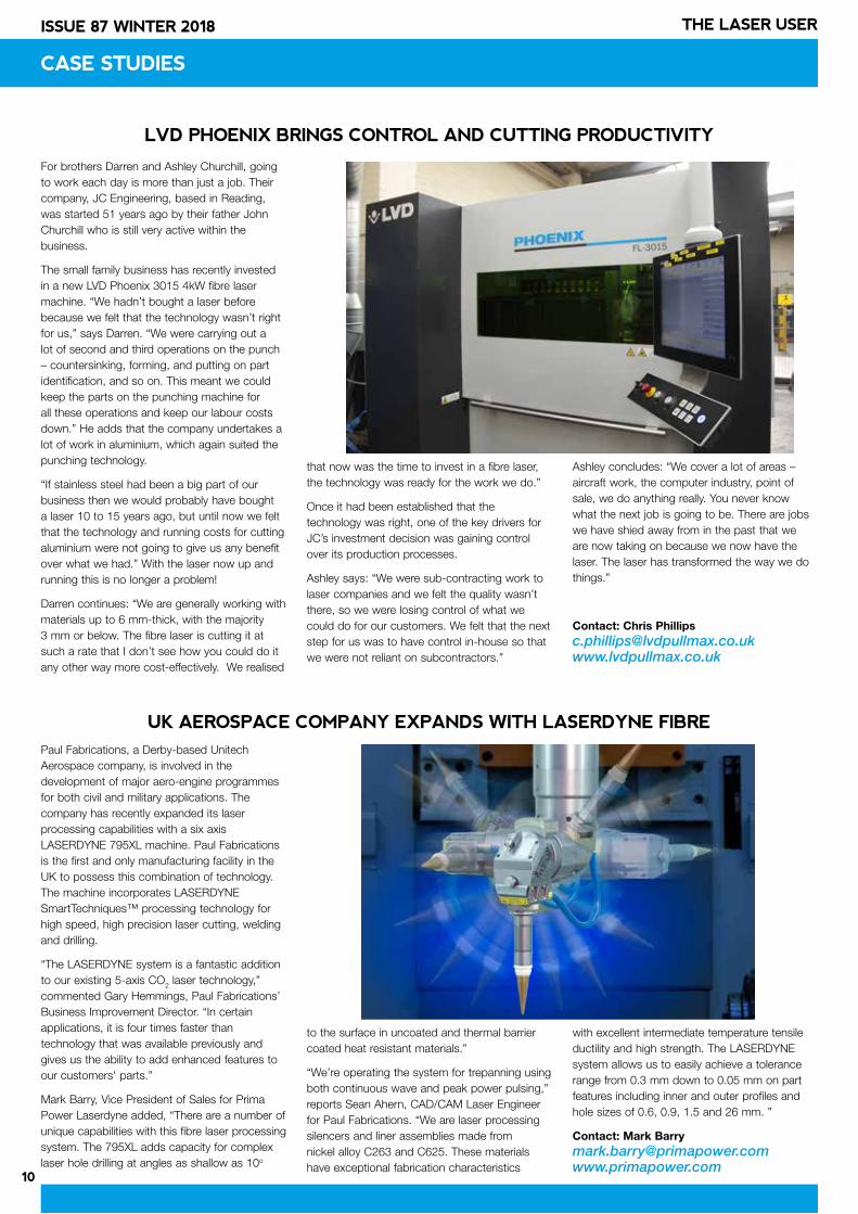
For brothers Darren and Ashley Churchill, going to work each day is more than just a job. Their company, JC Engineering, based in Reading, was started 51 years ago by their father John Churchill who is still very active within the business.
The small family business has recently invested in a new LVD Phoenix 3015 4kW fibre laser machine. “We hadn’t bought a laser before because we felt that the technology wasn’t right for us,” says Darren. “We were carrying out a lot of second and third operations on the punch – countersinking, forming, and putting on part identification, and so on. This meant we could keep the parts on the punching machine for all these operations and keep our labour costs down.” He adds that the company undertakes a lot of work in aluminium, which again suited the punching technology.
“If stainless steel had been a big part of our business then we would probably have bought a laser 10 to 15 years ago, but until now we felt that the technology and running costs for cutting aluminium were not going to give us any benefit over what we had.” With the laser now up and running this is no longer a problem!
Darren continues: “We are generally working with materials up to 6 mm-thick, with the majority 3 mm or below. The fibre laser is cutting it at such a rate that I don’t see how you could do it any other way more cost-effectively. We realised
that now was the time to invest in a fibre laser, the technology was ready for the work we do.”
Once it had been established that the technology was right, one of the key drivers for JC’s investment decision was gaining control over its production processes.
Ashley says: “We were sub-contracting work to laser companies and we felt the quality wasn’t there, so we were losing control of what we could do for our customers. We felt that the next step for us was to have control in-house so that we were not reliant on subcontractors.”
Ashley concludes: “We cover a lot of areas – aircraft work, the computer industry, point of sale, we do anything really. You never know what the next job is going to be. There are jobs we have shied away from in the past that we are now taking on because we now have the laser. The laser has transformed the way we do things.”
Contact: Chris [email protected] www.lvdpullmax.co.uk
LVD PHOENIX BRINGS CONTROL AND CUTTING PRODUCTIVITY
CASE STUDIES
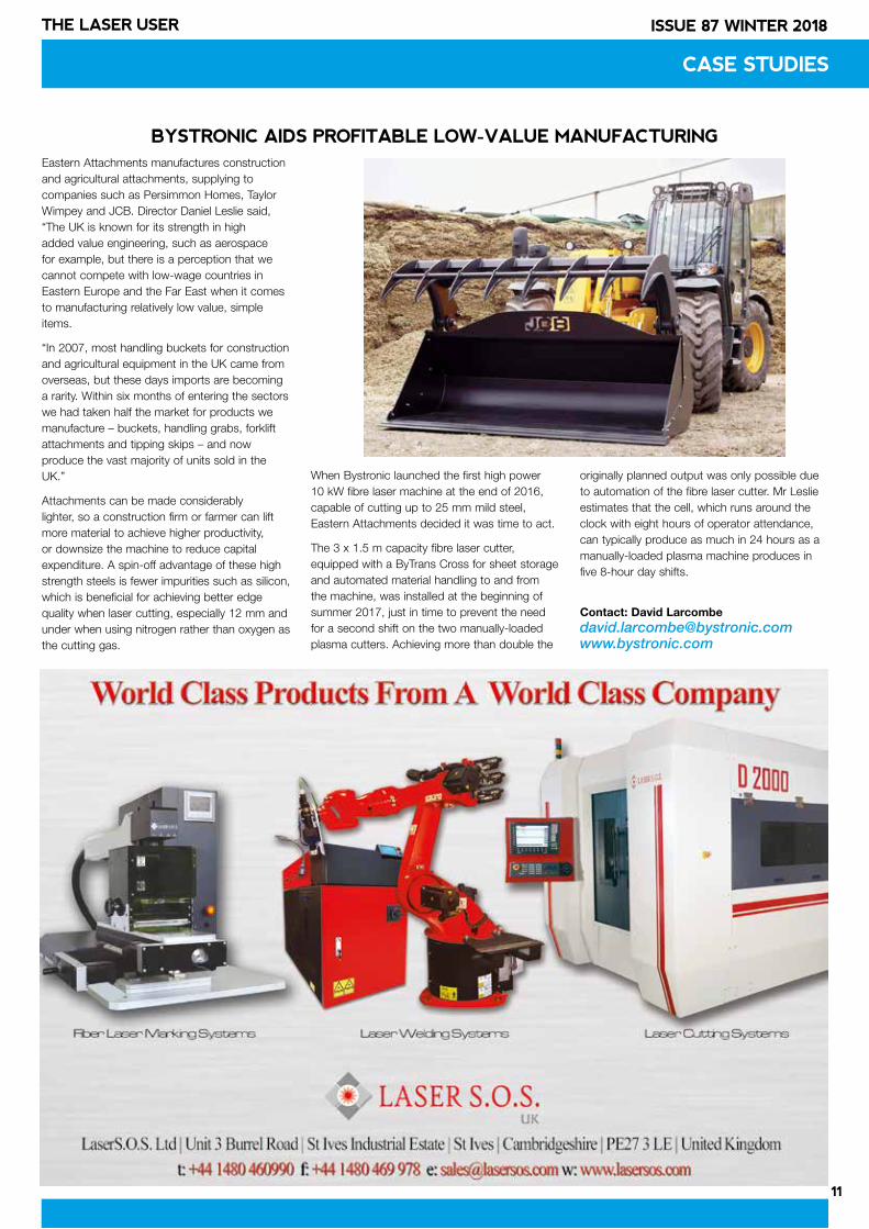
Paul Fabrications, a Derby-based Unitech Aerospace company, is involved in the development of major aero-engine programmes for both civil and military applications. The company has recently expanded its laser processing capabilities with a six axis LASERDYNE 795XL machine. Paul Fabrications is the first and only manufacturing facility in the UK to possess this combination of technology. The machine incorporates LASERDYNE SmartTechniques™ processing technology for high speed, high precision laser cutting, welding and drilling.
“The LASERDYNE system is a fantastic addition to our existing 5-axis CO2 laser technology,” commented Gary Hemmings, Paul Fabrications’ Business Improvement Director. “In certain applications, it is four times faster than technology that was available previously and gives us the ability to add enhanced features to our customers' parts.”
Mark Barry, Vice President of Sales for Prima Power Laserdyne added, “There are a number of unique capabilities with this fibre laser processing system. The 795XL adds capacity for complex laser hole drilling at angles as shallow as 10o
to the surface in uncoated and thermal barrier coated heat resistant materials.”
“We’re operating the system for trepanning using both continuous wave and peak power pulsing,” reports Sean Ahern, CAD/CAM Laser Engineer for Paul Fabrications. “We are laser processing silencers and liner assemblies made from nickel alloy C263 and C625. These materials have exceptional fabrication characteristics
with excellent intermediate temperature tensile ductility and high strength. The LASERDYNE system allows us to easily achieve a tolerance range from 0.3 mm down to 0.05 mm on part features including inner and outer profiles and hole sizes of 0.6, 0.9, 1.5 and 26 mm. ”
Contact: Mark [email protected]
UK AEROSPACE COMPANY EXPANDS WITH LASERDYNE FIBRE
11
ISSUE 87 WINTER 2018THE LASER USER
CASE STUDIES
BYSTRONIC AIDS PROFITABLE LOW-VALUE MANUFACTURINGEastern Attachments manufactures construction and agricultural attachments, supplying to companies such as Persimmon Homes, Taylor Wimpey and JCB. Director Daniel Leslie said, “The UK is known for its strength in high added value engineering, such as aerospace for example, but there is a perception that we cannot compete with low-wage countries in Eastern Europe and the Far East when it comes to manufacturing relatively low value, simple items.
“In 2007, most handling buckets for construction and agricultural equipment in the UK came from overseas, but these days imports are becoming a rarity. Within six months of entering the sectors we had taken half the market for products we manufacture – buckets, handling grabs, forklift attachments and tipping skips – and now produce the vast majority of units sold in the UK.”
Attachments can be made considerably lighter, so a construction firm or farmer can lift more material to achieve higher productivity, or downsize the machine to reduce capital expenditure. A spin-off advantage of these high strength steels is fewer impurities such as silicon, which is beneficial for achieving better edge quality when laser cutting, especially 12 mm and under when using nitrogen rather than oxygen as the cutting gas.
When Bystronic launched the first high power 10 kW fibre laser machine at the end of 2016, capable of cutting up to 25 mm mild steel, Eastern Attachments decided it was time to act.
The 3 x 1.5 m capacity fibre laser cutter, equipped with a ByTrans Cross for sheet storage and automated material handling to and from the machine, was installed at the beginning of summer 2017, just in time to prevent the need for a second shift on the two manually-loaded plasma cutters. Achieving more than double the
originally planned output was only possible due to automation of the fibre laser cutter. Mr Leslie estimates that the cell, which runs around the clock with eight hours of operator attendance, can typically produce as much in 24 hours as a manually-loaded plasma machine produces in five 8-hour day shifts.
Contact: David [email protected]
12
ISSUE 87 WINTER 2018 THE LASER USER
PRODUCT NEWS
12
INTERVIEW
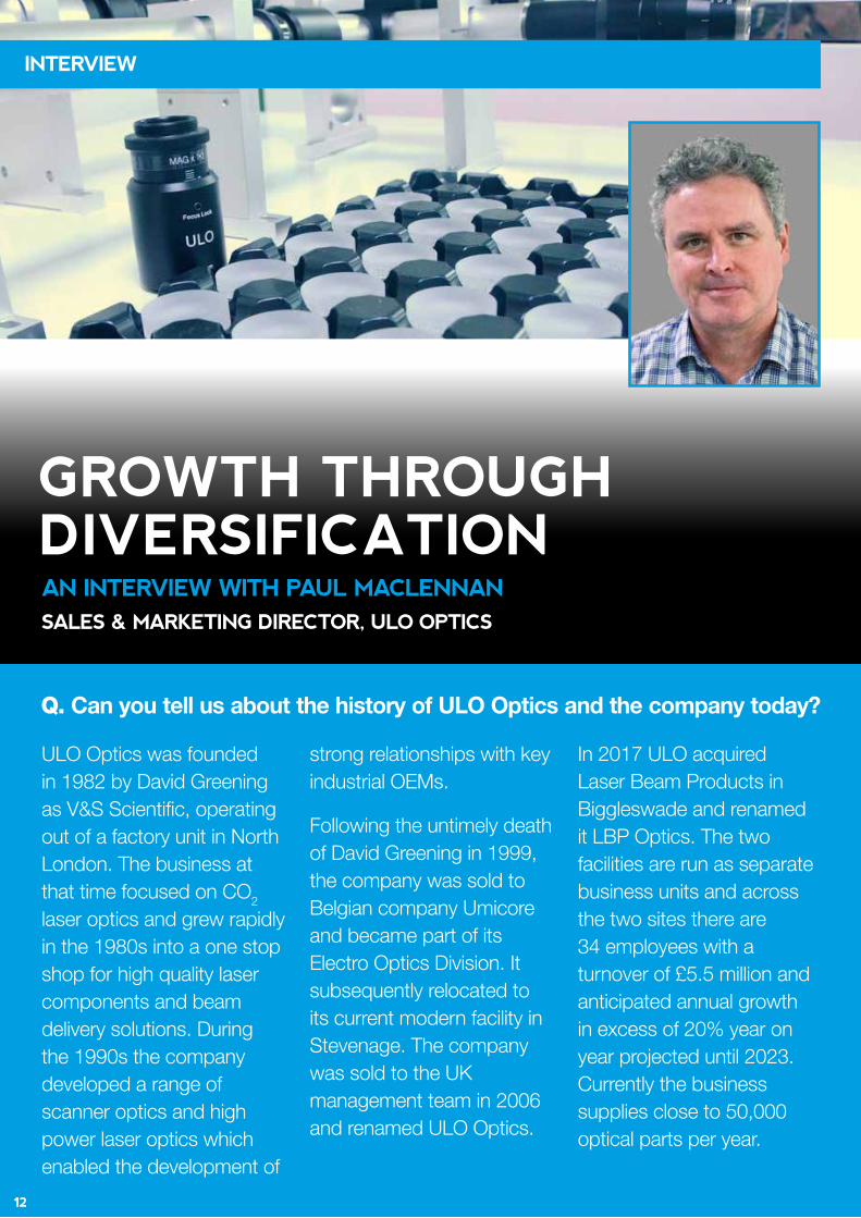
GROWTH THROUGH DIVERSIFICATION AN INTERVIEW WITH PAUL MACLENNAN
SALES & MARKETING DIRECTOR, ULO OPTICS
Q. Can you tell us about the history of ULO Optics and the company today?
ULO Optics was founded in 1982 by David Greening as V&S Scientific, operating out of a factory unit in North London. The business at that time focused on CO2 laser optics and grew rapidly in the 1980s into a one stop shop for high quality laser components and beam delivery solutions. During the 1990s the company developed a range of scanner optics and high power laser optics which enabled the development of
strong relationships with key industrial OEMs.
Following the untimely death of David Greening in 1999, the company was sold to Belgian company Umicore and became part of its Electro Optics Division. It subsequently relocated to its current modern facility in Stevenage. The company was sold to the UK management team in 2006 and renamed ULO Optics.
In 2017 ULO acquired Laser Beam Products in Biggleswade and renamed it LBP Optics. The two facilities are run as separate business units and across the two sites there are 34 employees with a turnover of £5.5 million and anticipated annual growth in excess of 20% year on year projected until 2023. Currently the business supplies close to 50,000 optical parts per year.
INTERVIEW
13
ISSUE 87 WINTER 2018THE LASER USER
INTERVIEW
Q. How does the acquisition of LBP Optics change your capabilities and objectives?
We’ve worked closely with LBP founder Mark Wilkinson since the 1980s and have always held a broadly similar business outlook. In all the years we’ve ordered mirrors from LBP, we have never had to reject a single optic - so we always knew the optical quality was literally second to none. More recently, Mark’s business has seen the potential for significant growth in two key areas: medical and defence. This ties in very well with ULO’s aim to further develop our presence in both these market sectors. Combining the metrology and experiences of both companies with our ISO 9001:2015 accreditation will help that process.
Q. How does the shift from CO2 to fibre lasers, especially in the past 5-10 years, affect your business?
Historically ULO and LBP have been mainly associated with CO2 laser optics. In the 1990s we took a long hard look at our product range; most of our business was UK based and CO2 related, so we realised that targeting the export market was needed as well as more than one wavelength band.
I think it was at an AILU Jobshop Meeting in Coventry, many years ago, that I first heard the phrase “Growth Through Diversification”. It impressed me as a concept and since then we’ve worked hard to attract business from new products and new sectors. We have recently diversified into one micron products, and hired Stuart McCulloch from SPI Lasers to grow that business. The success of fibre lasers is hugely important to our growth plans with products such as multi-element scanner lenses, protection windows and a newly launched range of collimators.
Intriguingly, the percentage of LBP’s customer base that have changed up to high power fibre lasers is only 15%. We’ve put this surprisingly low number down to mainly supplying low power CO2 OEMs, where applications such as polymer processing can’t easily be replaced with solid state laser alternatives. We have not seen a decline in demand for CO2 optics, despite the often announced demise of CO2, and this is complemented by additional growth in one micron optics and the new business from LBP.
Q. Is your biggest market OEMs or end users? How much of your business is export?
Overall ULO supplies 40% of its turnover to OEMs; LBP a much higher amount at 70%. With reference to the end user sector, ULO supplies 20% of its turnover and LBP 13%. ULO’s traditional route to market is via a strong network of distributors; currently we
rely on this approach for around a third of our turnover. We export over 80% of what we make in Stevenage, whilst at LBP, excluding a couple of major UK based customers, we export roughly 60% of what we make. One of our largest export customers is based in the EU medical sector.
Q. How do you see UK market conditions and future business with Europe post-Brexit?
Since the referendum we’ve seen over 50% growth in Europe, the favourable exchange rates having given us a competitive edge. How this will play out post-Brexit next year remains to be seen, but we are in a highly specialised market sector and our quality and service are excellent so we are confident that we will continue to remain competitive especially as much of our competition for CO2 products comes from outside the EU.
Regarding the one micron sector, our philosophy has always been to stay ahead of the competition by entering the market at the high value added end. We’ve been lucky enough to have been invited onto a couple of innovative projects; LaserSnake and ModuLase. The experience we’ve drawn from working on these programmes has given us a wonderful insight into the optics that are required to work properly at high power levels (greater than 5 kW).
Q. Is there anything new and exciting in the pipeline?
We are currently launching a new version of our affordable and modular CO2 beam delivery named Compact2, which offers double the aperture of our Compact Series, and twice the power (up to around 1 kW). We will soon launch a range of user-friendly beam collimators for one micron. Our Technical Director, Nick Ellis, continues to design amazing multi-element scanner lenses for both CO2, used extensively in the manufacture of smart phones, and one micron where they are used in the automotive sector.
Q. How has AILU membership benefited your company?
We have been hugely impressed with the ILAS events. They are very well run, always useful and enjoyable (even more so in the evenings). We’ve also enjoyed having a platform to deliver information through making presentations at workshops. Finally we regard the magazine as AILU’s pivotal epicentre – described by our founder David Greening as being the best of its type anywhere in the world.
Contact: Paul Maclennan [email protected]
The success of fibre lasers is hugely important to our
growth plans.
“
”
We have been hugely impressed with the
ILAS events.
“
”
GROWTH THROUGH DIVERSIFICATION
14
ISSUE 87 WINTER 2018 THE LASER USER
GRATNELLS INVESTMENT EXPANDS CAPABILITIES
Gratnells Engineering has recently invested in a new state-of-the-art BLM LT Fiber machine, allowing the company to expand their capabilities in 2018 and ensure clients benefit from even faster turnaround times.
The new machine sits next to an existing laser tube cutting machine which is designed to cut from small to medium diameters and thicknesses of metal tubular sections. The LT Fiber allows tubes of any shape to be cut without any additional special equipment required.
The new machine is already helping to increase factory efficiency by allowing unloading to various positions, with finished parts from one machine being unloaded whilst production continues uninterrupted on the other. The need to manually separate parts from different orders has also now been eliminated.
Tube laser cutting continues to grow in popularity as it offers a quick route to a precise finish, eliminating conventional, time-consuming stages such as marking out, sawing and finishing whilst delivering significant cost savings.
Contact: Murray [email protected]
Contact: Paul [email protected]
JOB SHOP CORNER
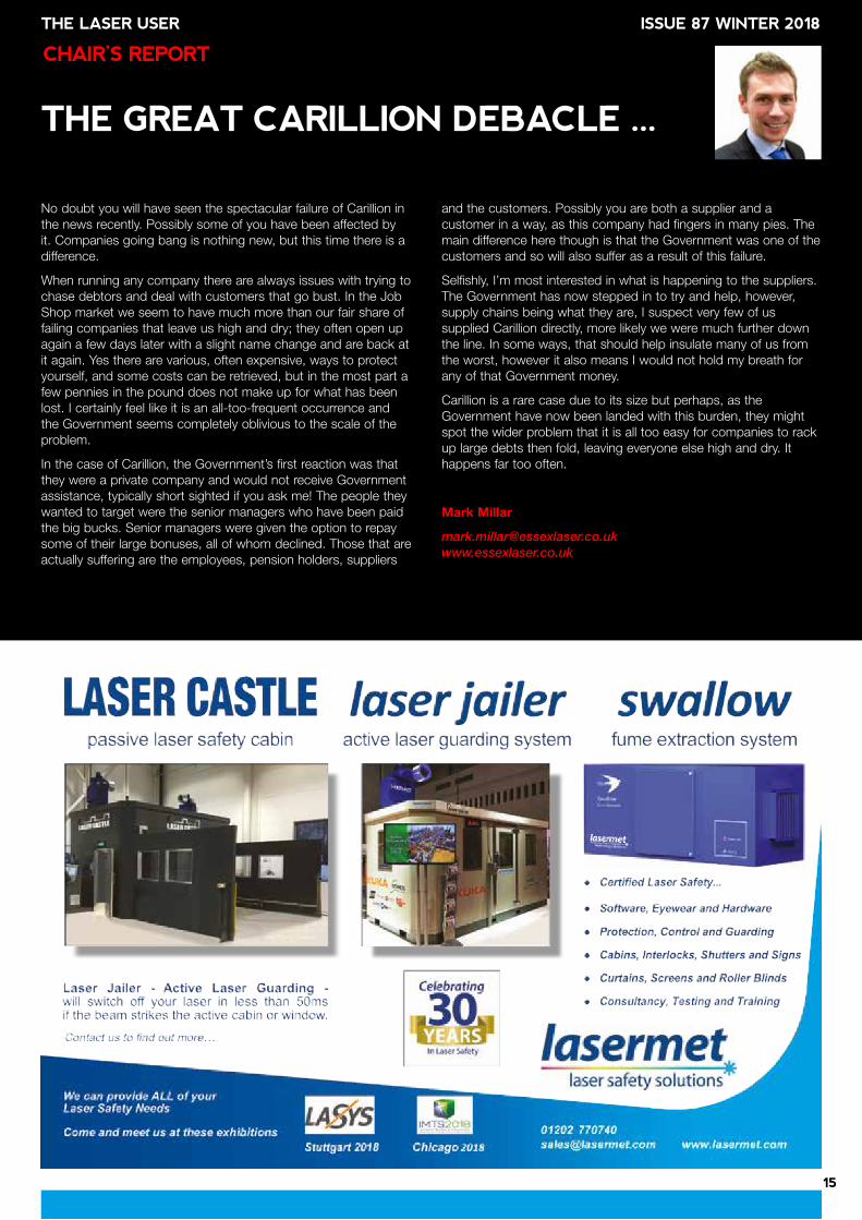
MALTON LASER GROWTH AND TRAININGIncrease in profits for 3rd consecutive year
Malton Laser has reported a turnover of £2.2 million for the past year, an increase of 18% compared to the previous 12 months. Moving forward, the company is aiming to increase its turnover by a further 20% over the next year, in order to position the business as one of the most forward-thinking, cutting-edge companies in the industry. This recent growth is partly thanks to the business’ investment in the most advanced, revolutionary laser cutting and welding technology.
MD graduates from prestigious training programme
Managing Director, Charles Corner, graduated from the 10,000 Small Businesses Training Programme at Oxford University after being selected from hundreds of business leaders to take part in the course. Set up with the aim of assisting businesses in reaching their full potential, the course aims to provide small business leaders with the skills and tools they need to effectively grow their businesses.
Contact: Charles [email protected]
Charles Corner, MD Malton Lasers
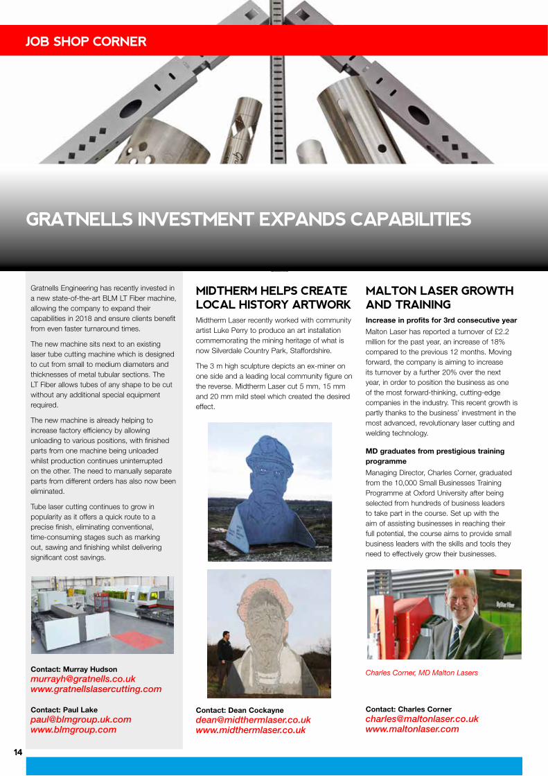
MIDTHERM HELPS CREATE LOCAL HISTORY ARTWORKMidtherm Laser recently worked with community artist Luke Perry to produce an art installation commemorating the mining heritage of what is now Silverdale Country Park, Staffordshire.
The 3 m high sculpture depicts an ex-miner on one side and a leading local community figure on the reverse. Midtherm Laser cut 5 mm, 15 mm and 20 mm mild steel which created the desired effect.
Contact: Dean [email protected]
15
ISSUE 87 WINTER 2018THE LASER USER
No doubt you will have seen the spectacular failure of Carillion in the news recently. Possibly some of you have been affected by it. Companies going bang is nothing new, but this time there is a difference.
When running any company there are always issues with trying to chase debtors and deal with customers that go bust. In the Job Shop market we seem to have much more than our fair share of failing companies that leave us high and dry; they often open up again a few days later with a slight name change and are back at it again. Yes there are various, often expensive, ways to protect yourself, and some costs can be retrieved, but in the most part a few pennies in the pound does not make up for what has been lost. I certainly feel like it is an all-too-frequent occurrence and the Government seems completely oblivious to the scale of the problem.
In the case of Carillion, the Government’s first reaction was that they were a private company and would not receive Government assistance, typically short sighted if you ask me! The people they wanted to target were the senior managers who have been paid the big bucks. Senior managers were given the option to repay some of their large bonuses, all of whom declined. Those that are actually suffering are the employees, pension holders, suppliers
and the customers. Possibly you are both a supplier and a customer in a way, as this company had fingers in many pies. The main difference here though is that the Government was one of the customers and so will also suffer as a result of this failure.
Selfishly, I’m most interested in what is happening to the suppliers. The Government has now stepped in to try and help, however, supply chains being what they are, I suspect very few of us supplied Carillion directly, more likely we were much further down the line. In some ways, that should help insulate many of us from the worst, however it also means I would not hold my breath for any of that Government money.
Carillion is a rare case due to its size but perhaps, as the Government have now been landed with this burden, they might spot the wider problem that it is all too easy for companies to rack up large debts then fold, leaving everyone else high and dry. It happens far too often.
Mark Millar
CHAIR’S REPORT
THE GREAT CARILLION DEBACLE ...
ISSUE 87 WINTER 2018THE LASER USER
16
ISSUE 87 WINTER 2018 THE LASER USER
FLUID AND PARTICLE DYNAMICS IN
LASER POWDER BED FUSION IOANNIS BITHARAS ET AL.*Laser powder bed fusion (LPBF) is currently the most widely adopted process for the additive manufacture of metallic components. Detailed visualisation studies recently revealed that the process is more dynamic than is generally appreciated and can involve considerable motion of powder particles and agglomerates in and above the powder bed. This motion is driven by the laser-induced plume of metal vapour and plasma above the melt pool.
Metal LPBF is a category of additive manufacture (AM) process in which thermal energy selectively fuses regions of a powder bed. Commercial LPBF systems are already used to manufacture components, but they require intensive, part-specific process setting refinements in order to reduce the distortions caused by residual stresses, to determine process settings that reduce defects and to determine acceptable positions for support structures. In the future, software will simulate a full-build and reduce the time required to determine process settings, but that approach still requires better process understanding so that residual stresses, porosity and surface finish are predicted reliably for different process regimes. Imaging and simulations are the two main approaches being used to achieve this improved understanding.
It is extremely challenging to record images through the viewing window of commercial LPBF systems with sufficient magnification or contrast to see individual powder particles in the powder bed. Due to this, such methods have been used mainly for build monitoring, rather than to understand the physics of the process. To overcome this problem, we have utilised an experimental open architecture LPBF system, designed to allow easy access to imaging whilst maintaining the capacity to print millimetre-scale fully dense parts. More details about this system have been presented in Issue 80 of The Laser User and in [1]. In this visualisation study [2], we employ a combination of high-speed imaging and schlieren imaging, as well as multiphysics modelling, to elucidate the effects of the interaction between the laser beam and the powder bed.
A Photron Fastcam Mini UX100 monochrome camera was used for high-speed imaging. The direct imaging experiments reported here were recorded at 8000 fps and 1280 × 616 pixels. The camera was fitted with a C-mount QiOptiq Optem Fusion lens, configured to provide a
zoom of 7:1. All the experiments reported here were undertaken with gas-atomised stainless steel 316L powder (Renishaw PLC) with particle diameters in the range 15–45 µm and a mean diameter of 30 µm. Powder layers were melted on to 2 mm thick stainless steel 304 L coupons, using a single mode fibre laser (SPI 400 W continuous wave, 1070 nm) which was scanned over the powder surface (Raylase MS-II-14 scanner with 163 mm focal length f-theta lens) with a 50 µm diameter Gaussian beam profile. The shielding chamber was purged with argon until the measured oxygen concentration was <0.1%.
Single line scans
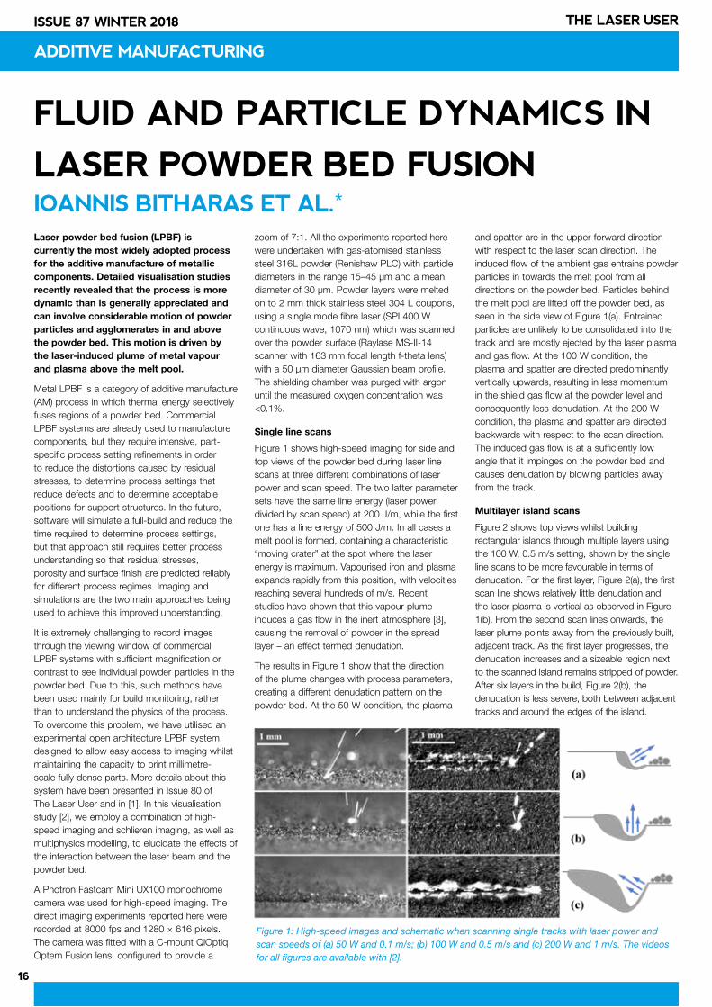
Figure 1 shows high-speed imaging for side and top views of the powder bed during laser line scans at three different combinations of laser power and scan speed. The two latter parameter sets have the same line energy (laser power divided by scan speed) at 200 J/m, while the first one has a line energy of 500 J/m. In all cases a melt pool is formed, containing a characteristic “moving crater” at the spot where the laser energy is maximum. Vapourised iron and plasma expands rapidly from this position, with velocities reaching several hundreds of m/s. Recent studies have shown that this vapour plume induces a gas flow in the inert atmosphere [3], causing the removal of powder in the spread layer – an effect termed denudation.
The results in Figure 1 show that the direction of the plume changes with process parameters, creating a different denudation pattern on the powder bed. At the 50 W condition, the plasma
and spatter are in the upper forward direction with respect to the laser scan direction. The induced flow of the ambient gas entrains powder particles in towards the melt pool from all directions on the powder bed. Particles behind the melt pool are lifted off the powder bed, as seen in the side view of Figure 1(a). Entrained particles are unlikely to be consolidated into the track and are mostly ejected by the laser plasma and gas flow. At the 100 W condition, the plasma and spatter are directed predominantly vertically upwards, resulting in less momentum in the shield gas flow at the powder level and consequently less denudation. At the 200 W condition, the plasma and spatter are directed backwards with respect to the scan direction. The induced gas flow is at a sufficiently low angle that it impinges on the powder bed and causes denudation by blowing particles away from the track.
Multilayer island scans
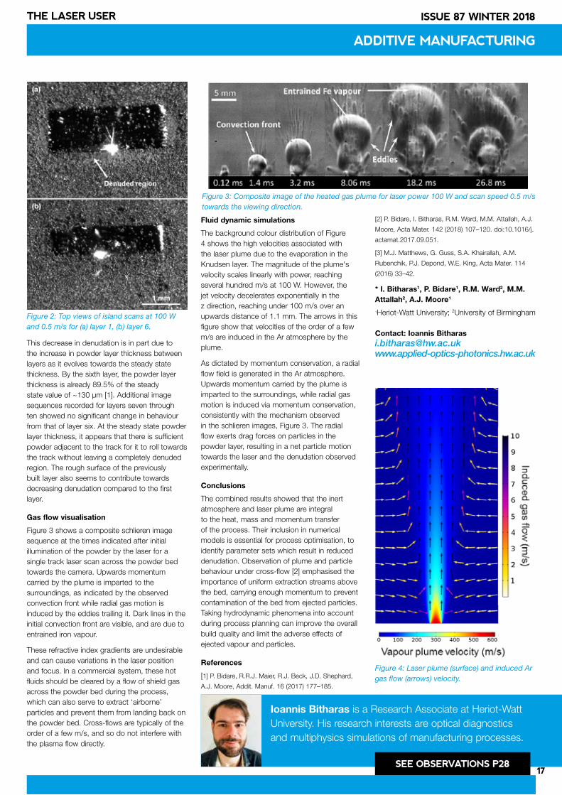
Figure 2 shows top views whilst building rectangular islands through multiple layers using the 100 W, 0.5 m/s setting, shown by the single line scans to be more favourable in terms of denudation. For the first layer, Figure 2(a), the first scan line shows relatively little denudation and the laser plasma is vertical as observed in Figure 1(b). From the second scan lines onwards, the laser plume points away from the previously built, adjacent track. As the first layer progresses, the denudation increases and a sizeable region next to the scanned island remains stripped of powder. After six layers in the build, Figure 2(b), the denudation is less severe, both between adjacent tracks and around the edges of the island.
ADDITIVE MANUFACTURING
Figure 1: High-speed images and schematic when scanning single tracks with laser power and scan speeds of (a) 50 W and 0.1 m/s; (b) 100 W and 0.5 m/s and (c) 200 W and 1 m/s. The videos for all figures are available with [2].
17
ISSUE 87 WINTER 2018THE LASER USER
This decrease in denudation is in part due to the increase in powder layer thickness between layers as it evolves towards the steady state thickness. By the sixth layer, the powder layer thickness is already 89.5% of the steady state value of ~130 µm [1]. Additional image sequences recorded for layers seven through ten showed no significant change in behaviour from that of layer six. At the steady state powder layer thickness, it appears that there is sufficient powder adjacent to the track for it to roll towards the track without leaving a completely denuded region. The rough surface of the previously built layer also seems to contribute towards decreasing denudation compared to the first layer.
Gas flow visualisation
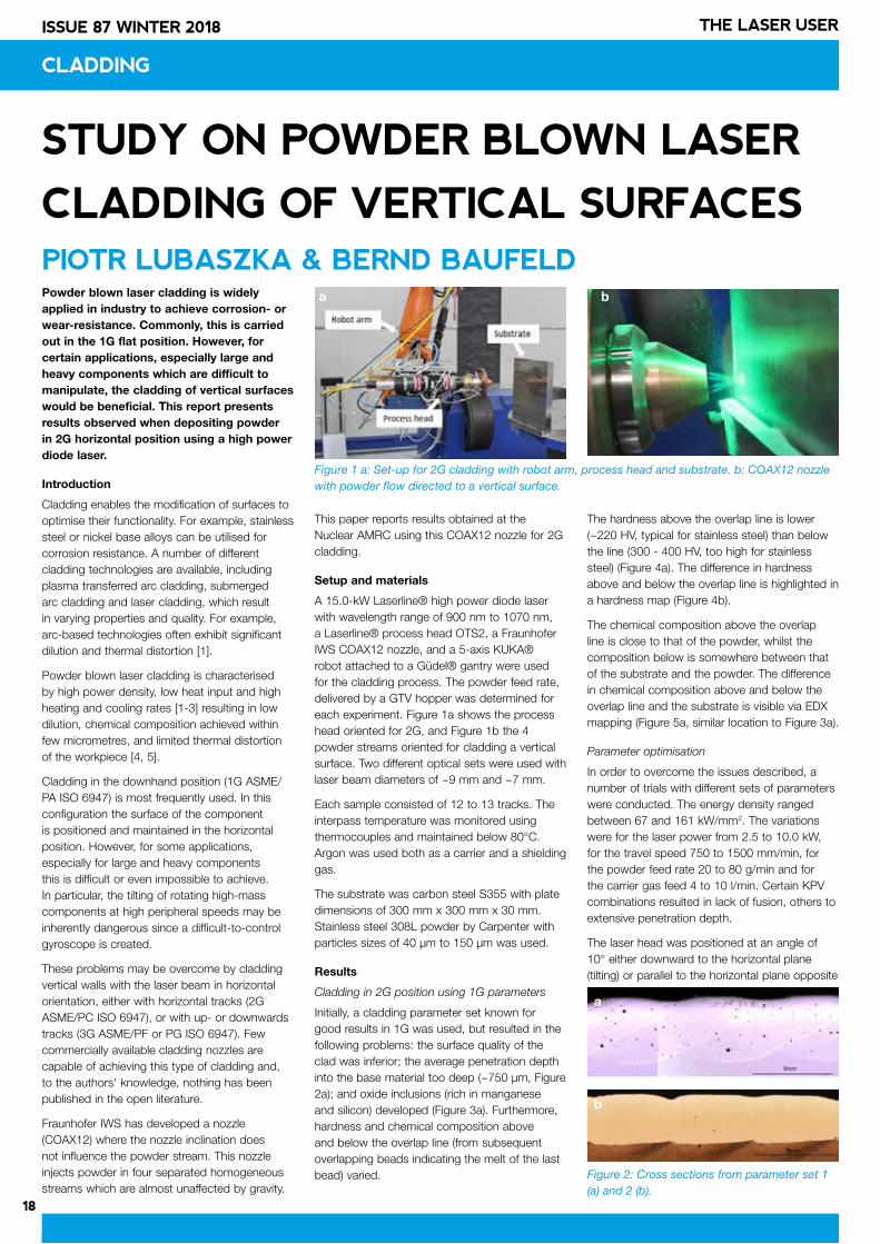
Figure 3 shows a composite schlieren image sequence at the times indicated after initial illumination of the powder by the laser for a single track laser scan across the powder bed towards the camera. Upwards momentum carried by the plume is imparted to the surroundings, as indicated by the observed convection front while radial gas motion is induced by the eddies trailing it. Dark lines in the initial convection front are visible, and are due to entrained iron vapour.
These refractive index gradients are undesirable and can cause variations in the laser position and focus. In a commercial system, these hot fluids should be cleared by a flow of shield gas across the powder bed during the process, which can also serve to extract ‘airborne’ particles and prevent them from landing back on the powder bed. Cross-flows are typically of the order of a few m/s, and so do not interfere with the plasma flow directly.
Fluid dynamic simulations
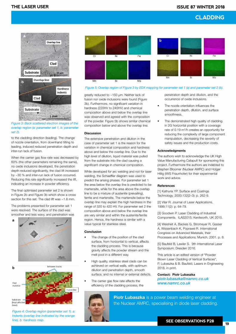
The background colour distribution of Figure 4 shows the high velocities associated with the laser plume due to the evaporation in the Knudsen layer. The magnitude of the plume's velocity scales linearly with power, reaching several hundred m/s at 100 W. However, the jet velocity decelerates exponentially in the z direction, reaching under 100 m/s over an upwards distance of 1.1 mm. The arrows in this figure show that velocities of the order of a few m/s are induced in the Ar atmosphere by the plume.
As dictated by momentum conservation, a radial flow field is generated in the Ar atmosphere. Upwards momentum carried by the plume is imparted to the surroundings, while radial gas motion is induced via momentum conservation, consistently with the mechanism observed in the schlieren images, Figure 3. The radial flow exerts drag forces on particles in the powder layer, resulting in a net particle motion towards the laser and the denudation observed experimentally.
Conclusions
The combined results showed that the inert atmosphere and laser plume are integral to the heat, mass and momentum transfer of the process. Their inclusion in numerical models is essential for process optimisation, to identify parameter sets which result in reduced denudation. Observation of plume and particle behaviour under cross-flow [2] emphasised the importance of uniform extraction streams above the bed, carrying enough momentum to prevent contamination of the bed from ejected particles. Taking hydrodynamic phenomena into account during process planning can improve the overall build quality and limit the adverse effects of ejected vapour and particles.
References
[1] P. Bidare, R.R.J. Maier, R.J. Beck, J.D. Shephard,
A.J. Moore, Addit. Manuf. 16 (2017) 177–185.
[2] P. Bidare, I. Bitharas, R.M. Ward, M.M. Attallah, A.J.
Moore, Acta Mater. 142 (2018) 107–120. doi:10.1016/j.
actamat.2017.09.051.
[3] M.J. Matthews, G. Guss, S.A. Khairallah, A.M.
Rubenchik, P.J. Depond, W.E. King, Acta Mater. 114
(2016) 33–42.
* I. Bitharas1, P. Bidare1, R.M. Ward2, M.M. Attallah2, A.J. Moore1
1Heriot-Watt University; 2University of Birmingham
Contact: Ioannis [email protected]
ADDITIVE MANUFACTURING
Figure 2: Top views of island scans at 100 W and 0.5 m/s for (a) layer 1, (b) layer 6.
Figure 4: Laser plume (surface) and induced Ar gas flow (arrows) velocity.
Figure 3: Composite image of the heated gas plume for laser power 100 W and scan speed 0.5 m/s towards the viewing direction.
Ioannis Bitharas is a Research Associate at Heriot-Watt University. His research interests are optical diagnostics and multiphysics simulations of manufacturing processes.
SEE OBSERVATIONS P28
18
ISSUE 87 WINTER 2018 THE LASER USER
PRODUCT NEWS
18
CLADDING
STUDY ON POWDER BLOWN LASER
CLADDING OF VERTICAL SURFACES PIOTR LUBASZKA & BERND BAUFELDPowder blown laser cladding is widely applied in industry to achieve corrosion- or wear-resistance. Commonly, this is carried out in the 1G flat position. However, for certain applications, especially large and heavy components which are difficult to manipulate, the cladding of vertical surfaces would be beneficial. This report presents results observed when depositing powder in 2G horizontal position using a high power diode laser.
Introduction
Cladding enables the modification of surfaces to optimise their functionality. For example, stainless steel or nickel base alloys can be utilised for corrosion resistance. A number of different cladding technologies are available, including plasma transferred arc cladding, submerged arc cladding and laser cladding, which result in varying properties and quality. For example, arc-based technologies often exhibit significant dilution and thermal distortion [1].
Powder blown laser cladding is characterised by high power density, low heat input and high heating and cooling rates [1-3] resulting in low dilution, chemical composition achieved within few micrometres, and limited thermal distortion of the workpiece [4, 5].
Cladding in the downhand position (1G ASME/PA ISO 6947) is most frequently used. In this configuration the surface of the component is positioned and maintained in the horizontal position. However, for some applications, especially for large and heavy components this is difficult or even impossible to achieve. In particular, the tilting of rotating high-mass components at high peripheral speeds may be inherently dangerous since a difficult-to-control gyroscope is created.
These problems may be overcome by cladding vertical walls with the laser beam in horizontal orientation, either with horizontal tracks (2G ASME/PC ISO 6947), or with up- or downwards tracks (3G ASME/PF or PG ISO 6947). Few commercially available cladding nozzles are capable of achieving this type of cladding and, to the authors' knowledge, nothing has been published in the open literature.
Fraunhofer IWS has developed a nozzle (COAX12) where the nozzle inclination does not influence the powder stream. This nozzle injects powder in four separated homogeneous streams which are almost unaffected by gravity.
This paper reports results obtained at the Nuclear AMRC using this COAX12 nozzle for 2G cladding.
Setup and materials
A 15.0-kW Laserline® high power diode laser with wavelength range of 900 nm to 1070 nm, a Laserline® process head OTS2, a Fraunhofer IWS COAX12 nozzle, and a 5-axis KUKA® robot attached to a Güdel® gantry were used for the cladding process. The powder feed rate, delivered by a GTV hopper was determined for each experiment. Figure 1a shows the process head oriented for 2G, and Figure 1b the 4 powder streams oriented for cladding a vertical surface. Two different optical sets were used with laser beam diameters of ~9 mm and ~7 mm.
Each sample consisted of 12 to 13 tracks. The interpass temperature was monitored using thermocouples and maintained below 80°C. Argon was used both as a carrier and a shielding gas.
The substrate was carbon steel S355 with plate dimensions of 300 mm x 300 mm x 30 mm. Stainless steel 308L powder by Carpenter with particles sizes of 40 µm to 150 µm was used.
Results
Cladding in 2G position using 1G parameters
Initially, a cladding parameter set known for good results in 1G was used, but resulted in the following problems: the surface quality of the clad was inferior; the average penetration depth into the base material too deep (~750 µm, Figure 2a); and oxide inclusions (rich in manganese and silicon) developed (Figure 3a). Furthermore, hardness and chemical composition above and below the overlap line (from subsequent overlapping beads indicating the melt of the last bead) varied.
The hardness above the overlap line is lower (~220 HV, typical for stainless steel) than below the line (300 - 400 HV, too high for stainless steel) (Figure 4a). The difference in hardness above and below the overlap line is highlighted in a hardness map (Figure 4b).
The chemical composition above the overlap line is close to that of the powder, whilst the composition below is somewhere between that of the substrate and the powder. The difference in chemical composition above and below the overlap line and the substrate is visible via EDX mapping (Figure 5a, similar location to Figure 3a).
Parameter optimisation
In order to overcome the issues described, a number of trials with different sets of parameters were conducted. The energy density ranged between 67 and 161 kW/mm2. The variations were for the laser power from 2.5 to 10.0 kW, for the travel speed 750 to 1500 mm/min, for the powder feed rate 20 to 80 g/min and for the carrier gas feed 4 to 10 l/min. Certain KPV combinations resulted in lack of fusion, others to extensive penetration depth.
The laser head was positioned at an angle of 10° either downward to the horizontal plane (tilting) or parallel to the horizontal plane opposite
Figure 2: Cross sections from parameter set 1 (a) and 2 (b).
Figure 1 a: Set-up for 2G cladding with robot arm, process head and substrate. b: COAX12 nozzle with powder flow directed to a vertical surface.
ba
b
a
19
ISSUE 87 WINTER 2018THE LASER USER
CLADDING
to the cladding direction (leading). The change of nozzle orientation, from downhand tilting to leading, induced reduced penetration depth and inter-run lack of fusion.
When the carrier gas flow rate was decreased by 60% (the other parameters remaining the same), no oxide inclusions developed, the penetration depth reduced significantly, the clad lift increased by ~30 % and inter-run lack of fusion occurred. Reducing this rate significantly increased the lift, indicating an increase in powder efficiency.
The final optimised parameter set 2 is shown in Figure 2b and Figure 3b which show a cross section for this set. The clad lift was ~1.8 mm.
The problems presented for parameter set 1 were resolved. The surface of the clad was smoother and less wavy, and penetration was
greatly reduced to ~150 µm. Neither lack of fusion nor oxide inclusions were found (Figure 3b). Furthermore, no significant variation in hardness (220HV to 240HV) and chemical composition above and below the overlap line was observed and agreed with the composition of the powder. Figure 5b shows similar chemical composition below and above the overlap line.
Discussion
The extensive penetration and dilution in the case of parameter set 1 is the reason for the variation in chemical composition and hardness above and below the overlap line. Due to the high level of dilution, liquid material was pulled from the substrate into the clad causing a significant change in chemical composition.
While developed for arc welding and not for laser welding, the Schaeffler diagram was used to predict the arising phases. For parameter set 1 the area below the overlap line is predicted to be martensite, while for the area above the overlap line to be a mixture of austenite (prevailing), ferrite and martensite. The martensite below the overlap line may explain the high hardness in the range of 320 to 420 HV. For parameter set 2 the composition above and below the overlap line are very similar and within the austenite/ferrite region. Hence, the hardness is similar with a value typical for stainless steel.
Conclusion
• The change of the position of the clad surface, from horizontal to vertical, affects the cladding process. This is because gravity affects the powder stream and the melt pool in a different way.
• High quality, stainless steel clads can be achieved on vertical walls, with optimum dilution and penetration depth, smooth surface, and no internal or external defects.
• The carrier gas flow rate affects the efficiency of the cladding process, the
penetration depth and dilution, and the occurrence of oxide inclusions.
• The nozzle orientation influences the penetration depth, dilution, and surface smoothness.
• The demonstrated high quality of cladding in 2G horizontal position with a coverage rate of 0.19 m2/h creates an opportunity for reducing the complexity of large component manipulation, decreasing the severity of safety issues and the production costs.
Acknowledgments
The authors wish to acknowledge the UK High Value Manufacturing Catapult for sponsoring this project. Furthermore the authors are indebted to Stephen Bloomer (Nuclear AMRC) and Holger Hillig (IWS Fraunhofer) for their experimental work and advice.
References
[1] Kathuria YP. Surface and Coatings Technology. 2000;132(2–3): p. 262-9.
[2] Vilar R. Journal of Laser Applications. 1999;11(2): p. 64-79.
[3] Goodwin P. Laser Cladding of Industrial Components. ILAS2015; Kenilworth, UK 2015.
[4] Weisheit A, Backes G, Stromeyer R, Gasser A, Wissenbach K, Poprawe R. International Congress on Advanced Materials, their Processes and Applications; Munich, 2001. p. 8.
[5] Baufeld B, Lawler S. 9th International Laser Symposium; Dresden 2016.
This article is an edited version of "Powder Blown Laser Cladding of Vertical Surfaces", P. Lubaszka & B. Baufeld, Lasers in Engineering 2018, in print.
Contact: Piotr [email protected]
Piotr Lubaszka is a power beam welding engineer at the Nuclear AMRC, specialising in diode laser cladding.
SEE OBSERVATIONS P28
Figure 3: Back scattered electron images of the overlap region (a: parameter set 1, b: parameter set 2).
Figure 4: Overlap region (parameter set 1). a: Indents (overlap line indicated by the orange line), b: hardness map.
Figure 5: Overlap region of Figure 3 by EDX mapping for parameter set 1 (a) and parameter set 2 (b).
a
b
a
b
ab
20
ISSUE 87 WINTER 2018 THE LASER USER
LASER WELDING PLASTICS –
A SHORT GUIDE IAN JONES
WELDING PLASTICS
Lasers are very attractive tools for joining sheet, film and moulded thermoplastics and textiles. Their features allow for a precise, yet rapid, delivery of a controlled amount of energy exactly to the point where it is required. Lasers are available with outputs covering a range of wavelengths, which has a large bearing on the interaction of the light with plastic materials. The nature of the process used is varied depending on the type, thickness and additives in the plastics. Complex forms can be welded using high resolution positioning and welds from less than 100 μm wide. This makes them suitable in a wide variety of applications including catheters, microfluidic devices, tubing, packaging, electronic cases and inflatable devices by using different material handling equipment.
Plastic types
Thermoplastics are polymer materials made from long chain molecules, that, above a certain temperature can be reshaped or welded. Unlike thermoset polymers, the molecular chains in thermoplastics are not cross-linked and do not have a rigid network. At high temperature the molecules are free to move and the material flows as a liquid. Industrial plastics have melting or softening temperatures in the range 120-343°C.
Thermoplastics may be split into semi-crystalline (milky appearance) and amorphous (glassy) types. Semi-crystalline types are a mixture of small crystallites surrounded by amorphous material. The crystallites scatter light giving rise to their outward appearance, and limit the transmission of laser radiation. This in turn, limits the maximum thickness that may be transmission laser welded. Some plastics can be made in both types but generally this is not the case. Plastics such as polyethylene (PE), polypropylene (PP), nylon (PA) and polyetheretherketone (PEEK) are semi-crystalline. Polycarbonate (PC), polymethylmethacrylate (PMMA) and polystyrene (PS) are amorphous.
Laser types and their interaction with plastics
The different applications possible with each laser type are very dependent on the wavelength of light produced, which dictates the form of energy absorption in the plastic.
The most common form of laser welding is the transmission method, in which the beam is
delivered through the upper part to the surface of the lower part where heating and melting takes place. The differential heating is controlled using laser absorbing additives or coatings at the lower part. A laser with a wavelength in the range 750-1500 nm is used and this may be provided by diode, fibre and Nd:YAG laser types. In general, this wavelength of radiation is absorbed far less readily in plastics than UV or mid-IR radiation. The degree of energy absorption in this range depends largely on the presence of additives in the plastics and whether the plastic is semi-crystalline or amorphous (glassy). If no fillers or pigments are present in the plastic, the laser will penetrate a few millimetres into semi-crystalline plastics and and is hardly attenuated at all in amorphous plastics. The absorption can be increased by means of additives such as pigments or fillers, especially carbon black pigment.
The absorption of radiation by natural unpigmented plastics increases from 1.6 µm wavelength upwards until there is very strong absorption for IR wavelengths longer than 5 µm. At a wavelength of 2 µm, which may be provided by a fibre laser or Holmium:YAG laser, the energy from the beam is deposited in the top few millimetres of all plastics (semi-crystalline or amorphous). Welding is possible in sheet up to a few millimetres thick without the need for additional absorbers. This is termed direct laser welding because the beam is not transmitted through an upper part to the joint line. Direct laser welding is not yet widely applied for joining plastics, but has potential for wider use.
The CO2 laser is a well established materials processing tool, commonly used for cutting plastics in film, sheet and fabric form. The CO2 laser radiation (10.6 µm wavelength) is rapidly absorbed in the surface layers of all plastics. The energy is delivered as heat in the first 0.2 mm of plastic that the laser is directed to. This leads to rapid heating, and very rapid weld processing of thin plastic film is possible, even with fairly modest laser powers (<1000 W). Welding speeds in excess of 1000 m/min have been demonstrated.
Transmission laser welding
When first being reported in 1985, transmission laser welding was carried out with an infrared transmissive plastic material for the upper section and a carbon black loaded plastic for the lower layer. The carbon black absorbs and heats in the laser beam to generate a
weld at the interface between the two pieces. The process is limited by the fact that one side of the component has to be black, but is still the most common application of the process. The upper part must transmit a proportion of the laser energy (more that 10% is usually enough), so that heating preferentially takes place at the surface of the lower part rather than at the upper surface of the top part. An example magnified at the joint interface can be seen in Figure 1. This image, with an almost equal melt depth in the two materials, shows that heating is developed very locally at the black surface. The black surface acts as a heating element within the part and provides for rapid processing, minimal thermal damage of surrounding components, and minimal distortion or contamination at the joint.
The advent of alternative absorbers for laser welding in 1998 allowed the joint to have much less visible colour. One example is called Clearweld. It is an infrared absorbing dye, much like other visibly coloured dyes. It can be applied as a coating (by spraying, printing, pad, needle or pen) at the joint line or added to the lower part (Figure 2). An example of a welded product made by applying absorber to the joint surface between two transparent parts of PMMA can be seen in Figure 3. Nearly all colour combinations can now be welded using transmission laser welding. The main problems arise with heavily filled plastics, where the upper part will not allow the beam to pass through to the joint. In these cases, the filler must be reduced or changed in particle size to reduce scattering, or another welding process should be considered.
Figure 1: Laser transmission weld in polypropylene showing the melt zone evenly affecting the carbon black filled and unpigmented plastic layers indicating that all the remaining energy is absorbed immediately at the surface of the black material. Courtesy TWI.
}
Mel
t zo
ne 0
.36m
m d
eep
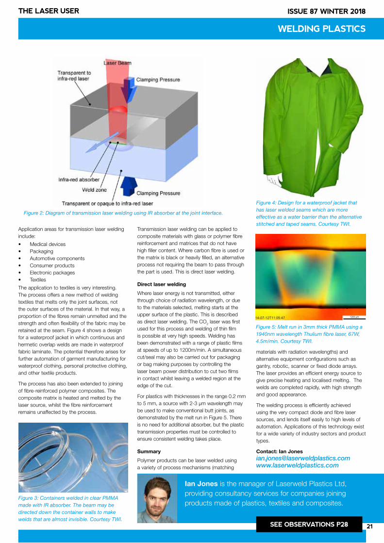
21
ISSUE 87 WINTER 2018THE LASER USER
Application areas for transmission laser welding include:
• Medical devices• Packaging• Automotive components• Consumer products• Electronic packages• Textiles
The application to textiles is very interesting. The process offers a new method of welding textiles that melts only the joint surfaces, not the outer surfaces of the material. In that way, a proportion of the fibres remain unmelted and the strength and often flexibility of the fabric may be retained at the seam. Figure 4 shows a design for a waterproof jacket in which continuous and hermetic overlap welds are made in waterproof fabric laminate. The potential therefore arises for further automation of garment manufacturing for waterproof clothing, personal protective clothing, and other textile products.
The process has also been extended to joining of fibre-reinforced polymer composites. The composite matrix is heated and melted by the laser source, whilst the fibre reinforcement remains unaffected by the process.
Transmission laser welding can be applied to composite materials with glass or polymer fibre reinforcement and matrices that do not have high filler content. Where carbon fibre is used or the matrix is black or heavily filled, an alternative process not requiring the beam to pass through the part is used. This is direct laser welding.
Direct laser welding
Where laser energy is not transmitted, either through choice of radiation wavelength, or due to the materials selected, melting starts at the upper surface of the plastic. This is described as direct laser welding. The CO2 laser was first used for this process and welding of thin film is possible at very high speeds. Welding has been demonstrated with a range of plastic films at speeds of up to 1200m/min. A simultaneous cut/seal may also be carried out for packaging or bag making purposes by controlling the laser beam power distribution to cut two films in contact whilst leaving a welded region at the edge of the cut.
For plastics with thicknesses in the range 0.2 mm to 5 mm, a source with 2-3 µm wavelength may be used to make conventional butt joints, as demonstrated by the melt run in Figure 5. There is no need for additional absorber, but the plastic transmission properties must be controlled to ensure consistent welding takes place.
Summary
Polymer products can be laser welded using a variety of process mechanisms (matching
materials with radiation wavelengths) and alternative equipment configurations such as gantry, robotic, scanner or fixed diode arrays. The laser provides an efficient energy source to give precise heating and localised melting. The welds are completed rapidly, with high strength and good appearance.
The welding process is efficiently achieved using the very compact diode and fibre laser sources, and lends itself easily to high levels of automation. Applications of this technology exist for a wide variety of industry sectors and product types.
Contact: Ian [email protected]
WELDING PLASTICS
Figure 2: Diagram of transmission laser welding using IR absorber at the joint interface.
Figure 3: Containers welded in clear PMMA made with IR absorber. The beam may be directed down the container walls to make welds that are almost invisible. Courtesy TWI.
Figure 4: Design for a waterproof jacket that has laser welded seams which are more effective as a water barrier than the alternative stitched and taped seams. Courtesy TWI.
Figure 5: Melt run in 3mm thick PMMA using a 1940nm wavelength Thulium fibre laser, 67W, 4.5m/min. Courtesy TWI.
Ian Jones is the manager of Laserweld Plastics Ltd, providing consultancy services for companies joining products made of plastics, textiles and composites.
SEE OBSERVATIONS P28
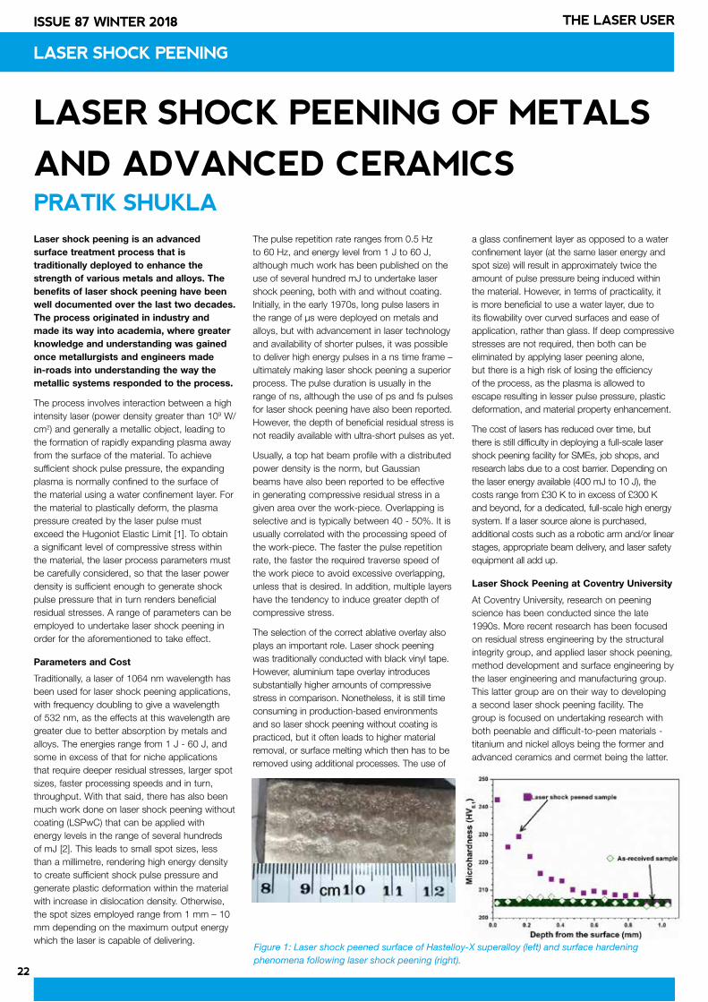
22
ISSUE 87 WINTER 2018 THE LASER USER
LASER SHOCK PEENING
LASER SHOCK PEENING OF METALS
AND ADVANCED CERAMICSPRATIK SHUKLA Laser shock peening is an advanced surface treatment process that is traditionally deployed to enhance the strength of various metals and alloys. The benefits of laser shock peening have been well documented over the last two decades. The process originated in industry and made its way into academia, where greater knowledge and understanding was gained once metallurgists and engineers made in-roads into understanding the way the metallic systems responded to the process.
The process involves interaction between a high intensity laser (power density greater than 109 W/cm2) and generally a metallic object, leading to the formation of rapidly expanding plasma away from the surface of the material. To achieve sufficient shock pulse pressure, the expanding plasma is normally confined to the surface of the material using a water confinement layer. For the material to plastically deform, the plasma pressure created by the laser pulse must exceed the Hugoniot Elastic Limit [1]. To obtain a significant level of compressive stress within the material, the laser process parameters must be carefully considered, so that the laser power density is sufficient enough to generate shock pulse pressure that in turn renders beneficial residual stresses. A range of parameters can be employed to undertake laser shock peening in order for the aforementioned to take effect.
Parameters and Cost
Traditionally, a laser of 1064 nm wavelength has been used for laser shock peening applications, with frequency doubling to give a wavelength of 532 nm, as the effects at this wavelength are greater due to better absorption by metals and alloys. The energies range from 1 J - 60 J, and some in excess of that for niche applications that require deeper residual stresses, larger spot sizes, faster processing speeds and in turn, throughput. With that said, there has also been much work done on laser shock peening without coating (LSPwC) that can be applied with energy levels in the range of several hundreds of mJ [2]. This leads to small spot sizes, less than a millimetre, rendering high energy density to create sufficient shock pulse pressure and generate plastic deformation within the material with increase in dislocation density. Otherwise, the spot sizes employed range from 1 mm – 10 mm depending on the maximum output energy which the laser is capable of delivering.
The pulse repetition rate ranges from 0.5 Hz to 60 Hz, and energy level from 1 J to 60 J, although much work has been published on the use of several hundred mJ to undertake laser shock peening, both with and without coating. Initially, in the early 1970s, long pulse lasers in the range of µs were deployed on metals and alloys, but with advancement in laser technology and availability of shorter pulses, it was possible to deliver high energy pulses in a ns time frame – ultimately making laser shock peening a superior process. The pulse duration is usually in the range of ns, although the use of ps and fs pulses for laser shock peening have also been reported. However, the depth of beneficial residual stress is not readily available with ultra-short pulses as yet.
Usually, a top hat beam profile with a distributed power density is the norm, but Gaussian beams have also been reported to be effective in generating compressive residual stress in a given area over the work-piece. Overlapping is selective and is typically between 40 - 50%. It is usually correlated with the processing speed of the work-piece. The faster the pulse repetition rate, the faster the required traverse speed of the work piece to avoid excessive overlapping, unless that is desired. In addition, multiple layers have the tendency to induce greater depth of compressive stress.
The selection of the correct ablative overlay also plays an important role. Laser shock peening was traditionally conducted with black vinyl tape. However, aluminium tape overlay introduces substantially higher amounts of compressive stress in comparison. Nonetheless, it is still time consuming in production-based environments and so laser shock peening without coating is practiced, but it often leads to higher material removal, or surface melting which then has to be removed using additional processes. The use of
a glass confinement layer as opposed to a water confinement layer (at the same laser energy and spot size) will result in approximately twice the amount of pulse pressure being induced within the material. However, in terms of practicality, it is more beneficial to use a water layer, due to its flowability over curved surfaces and ease of application, rather than glass. If deep compressive stresses are not required, then both can be eliminated by applying laser peening alone, but there is a high risk of losing the efficiency of the process, as the plasma is allowed to escape resulting in lesser pulse pressure, plastic deformation, and material property enhancement.
The cost of lasers has reduced over time, but there is still difficulty in deploying a full-scale laser shock peening facility for SMEs, job shops, and research labs due to a cost barrier. Depending on the laser energy available (400 mJ to 10 J), the costs range from £30 K to in excess of £300 K and beyond, for a dedicated, full-scale high energy system. If a laser source alone is purchased, additional costs such as a robotic arm and/or linear stages, appropriate beam delivery, and laser safety equipment all add up.
Laser Shock Peening at Coventry University
At Coventry University, research on peening science has been conducted since the late 1990s. More recent research has been focused on residual stress engineering by the structural integrity group, and applied laser shock peening, method development and surface engineering by the laser engineering and manufacturing group. This latter group are on their way to developing a second laser shock peening facility. The group is focused on undertaking research with both peenable and difficult-to-peen materials - titanium and nickel alloys being the former and advanced ceramics and cermet being the latter.
Figure 1: Laser shock peened surface of Hastelloy-X superalloy (left) and surface hardening phenomena following laser shock peening (right).
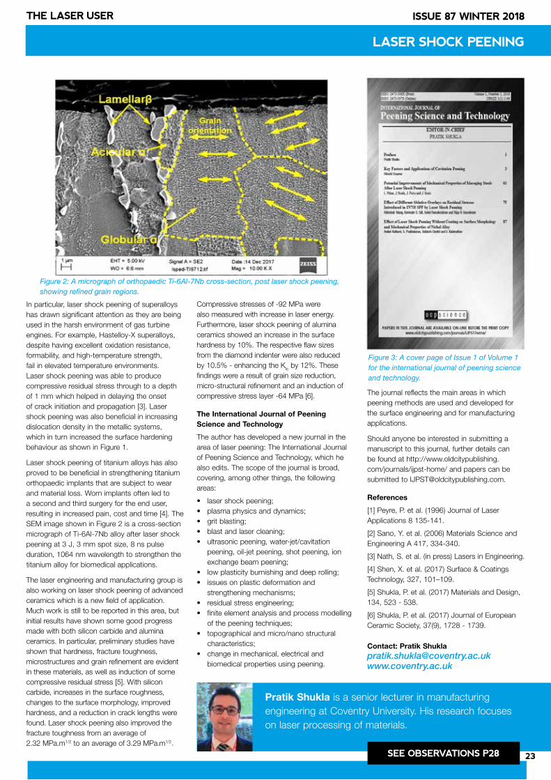
23
ISSUE 87 WINTER 2018THE LASER USER
In particular, laser shock peening of superalloys has drawn significant attention as they are being used in the harsh environment of gas turbine engines. For example, Hastelloy-X superalloys, despite having excellent oxidation resistance, formability, and high-temperature strength, fail in elevated temperature environments. Laser shock peening was able to produce compressive residual stress through to a depth of 1 mm which helped in delaying the onset of crack initiation and propagation [3]. Laser shock peening was also beneficial in increasing dislocation density in the metallic systems, which in turn increased the surface hardening behaviour as shown in Figure 1.
Laser shock peening of titanium alloys has also proved to be beneficial in strengthening titanium orthopaedic implants that are subject to wear and material loss. Worn implants often led to a second and third surgery for the end user, resulting in increased pain, cost and time [4]. The SEM image shown in Figure 2 is a cross-section micrograph of Ti-6Al-7Nb alloy after laser shock peening at 3 J, 3 mm spot size, 8 ns pulse duration, 1064 nm wavelength to strengthen the titanium alloy for biomedical applications.
The laser engineering and manufacturing group is also working on laser shock peening of advanced ceramics which is a new field of application. Much work is still to be reported in this area, but initial results have shown some good progress made with both silicon carbide and alumina ceramics. In particular, preliminary studies have shown that hardness, fracture toughness, microstructures and grain refinement are evident in these materials, as well as induction of some compressive residual stress [5]. With silicon carbide, increases in the surface roughness, changes to the surface morphology, improved hardness, and a reduction in crack lengths were found. Laser shock peening also improved the fracture toughness from an average of 2.32 MPa.m1/2 to an average of 3.29 MPa m1/2
Compressive stresses of -92 MPa were also measured with increase in laser energy. Furthermore, laser shock peening of alumina ceramics showed an increase in the surface hardness by 10%. The respective flaw sizes from the diamond indenter were also reduced by 10.5% - enhancing the KIc by 12%. These findings were a result of grain size reduction, micro-structural refinement and an induction of compressive stress layer -64 MPa [6].
The International Journal of Peening Science and Technology
The author has developed a new journal in the area of laser peening: The International Journal of Peening Science and Technology, which he also edits. The scope of the journal is broad, covering, among other things, the following areas:
• laser shock peening; • plasma physics and dynamics; • grit blasting; • blast and laser cleaning; • ultrasonic peening, water-jet/cavitation
peening, oil-jet peening, shot peening, ion exchange beam peening;
• low plasticity burnishing and deep rolling; • issues on plastic deformation and
strengthening mechanisms; • residual stress engineering; • finite element analysis and process modelling
of the peening techniques;• topographical and micro/nano structural
characteristics; • change in mechanical, electrical and
biomedical properties using peening.
The journal reflects the main areas in which peening methods are used and developed for the surface engineering and for manufacturing applications.
Should anyone be interested in submitting a manuscript to this journal, further details can be found at http://www.oldcitypublishing.com/journals/ijpst-home/ and papers can be submitted to [email protected].
References
[1] Peyre, P. et al. (1996) Journal of Laser Applications 8 135-141.
[2] Sano, Y. et al. (2006) Materials Science and Engineering A 417, 334-340.
[3] Nath, S. et al. (in press) Lasers in Engineering.
[4] Shen, X. et al. (2017) Surface & Coatings Technology, 327, 101–109.
[5] Shukla, P. et al. (2017) Materials and Design, 134, 523 - 538.
[6] Shukla, P. et al. (2017) Journal of European Ceramic Society, 37(9), 1728 - 1739.
Contact: Pratik [email protected]
Pratik Shukla is a senior lecturer in manufacturing engineering at Coventry University. His research focuses on laser processing of materials.
SEE OBSERVATIONS P28
LASER SHOCK PEENING
Figure 2: A micrograph of orthopaedic Ti-6Al-7Nb cross-section, post laser shock peening, showing refined grain regions.
Figure 3: A cover page of Issue 1 of Volume 1 for the international journal of peening science and technology.
. .
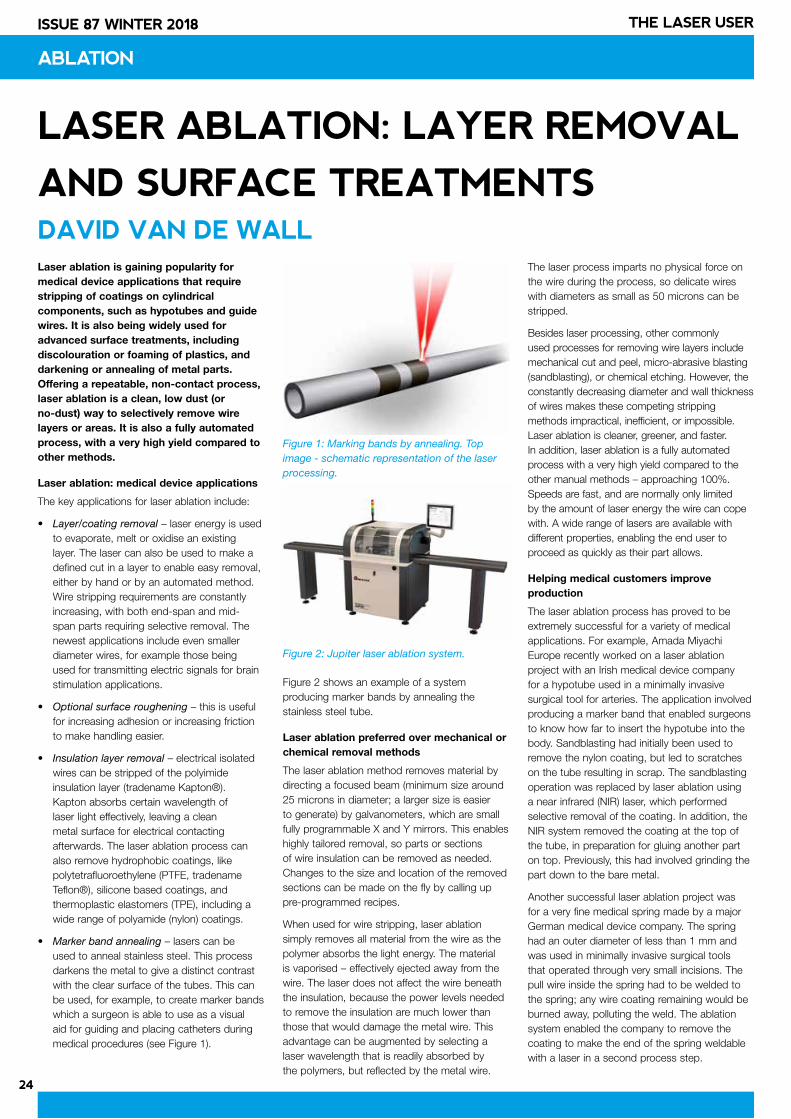
24
ISSUE 87 WINTER 2018 THE LASER USER
ABLATION
LASER ABLATION: LAYER REMOVAL
AND SURFACE TREATMENTSDAVID VAN DE WALLLaser ablation is gaining popularity for medical device applications that require stripping of coatings on cylindrical components, such as hypotubes and guide wires. It is also being widely used for advanced surface treatments, including discolouration or foaming of plastics, and darkening or annealing of metal parts. Offering a repeatable, non-contact process, laser ablation is a clean, low dust (or no-dust) way to selectively remove wire layers or areas. It is also a fully automated process, with a very high yield compared to other methods.
Laser ablation: medical device applications
The key applications for laser ablation include:
• Layer/coating removal – laser energy is used to evaporate, melt or oxidise an existing layer. The laser can also be used to make a defined cut in a layer to enable easy removal, either by hand or by an automated method. Wire stripping requirements are constantly increasing, with both end-span and mid-span parts requiring selective removal. The newest applications include even smaller diameter wires, for example those being used for transmitting electric signals for brain stimulation applications.
• Optional surface roughening – this is useful for increasing adhesion or increasing friction to make handling easier.
• Insulation layer removal – electrical isolated wires can be stripped of the polyimide insulation layer (tradename Kapton®). Kapton absorbs certain wavelength of laser light effectively, leaving a clean metal surface for electrical contacting afterwards. The laser ablation process can also remove hydrophobic coatings, like polytetrafluoroethylene (PTFE, tradename Teflon®), silicone based coatings, and thermoplastic elastomers (TPE), including a wide range of polyamide (nylon) coatings.
• Marker band annealing – lasers can be used to anneal stainless steel. This process darkens the metal to give a distinct contrast with the clear surface of the tubes. This can be used, for example, to create marker bands which a surgeon is able to use as a visual aid for guiding and placing catheters during medical procedures (see Figure 1).
Figure 2 shows an example of a system producing marker bands by annealing the stainless steel tube.
Laser ablation preferred over mechanical or chemical removal methods
The laser ablation method removes material by directing a focused beam (minimum size around 25 microns in diameter; a larger size is easier to generate) by galvanometers, which are small fully programmable X and Y mirrors. This enables highly tailored removal, so parts or sections of wire insulation can be removed as needed. Changes to the size and location of the removed sections can be made on the fly by calling up pre-programmed recipes.
When used for wire stripping, laser ablation simply removes all material from the wire as the polymer absorbs the light energy. The material is vaporised – effectively ejected away from the wire. The laser does not affect the wire beneath the insulation, because the power levels needed to remove the insulation are much lower than those that would damage the metal wire. This advantage can be augmented by selecting a laser wavelength that is readily absorbed by the polymers, but reflected by the metal wire.
The laser process imparts no physical force on the wire during the process, so delicate wires with diameters as small as 50 microns can be stripped.
Besides laser processing, other commonly used processes for removing wire layers include mechanical cut and peel, micro-abrasive blasting (sandblasting), or chemical etching. However, the constantly decreasing diameter and wall thickness of wires makes these competing stripping methods impractical, inefficient, or impossible. Laser ablation is cleaner, greener, and faster. In addition, laser ablation is a fully automated process with a very high yield compared to the other manual methods – approaching 100%. Speeds are fast, and are normally only limited by the amount of laser energy the wire can cope with. A wide range of lasers are available with different properties, enabling the end user to proceed as quickly as their part allows.
Helping medical customers improve production
The laser ablation process has proved to be extremely successful for a variety of medical applications. For example, Amada Miyachi Europe recently worked on a laser ablation project with an Irish medical device company for a hypotube used in a minimally invasive surgical tool for arteries. The application involved producing a marker band that enabled surgeons to know how far to insert the hypotube into the body. Sandblasting had initially been used to remove the nylon coating, but led to scratches on the tube resulting in scrap. The sandblasting operation was replaced by laser ablation using a near infrared (NIR) laser, which performed selective removal of the coating. In addition, the NIR system removed the coating at the top of the tube, in preparation for gluing another part on top. Previously, this had involved grinding the part down to the bare metal.
Another successful laser ablation project was for a very fine medical spring made by a major German medical device company. The spring had an outer diameter of less than 1 mm and was used in minimally invasive surgical tools that operated through very small incisions. The pull wire inside the spring had to be welded to the spring; any wire coating remaining would be burned away, polluting the weld. The ablation system enabled the company to remove the coating to make the end of the spring weldable with a laser in a second process step.
Figure 1: Marking bands by annealing. Top image - schematic representation of the laser processing.
Figure 2: Jupiter laser ablation system.
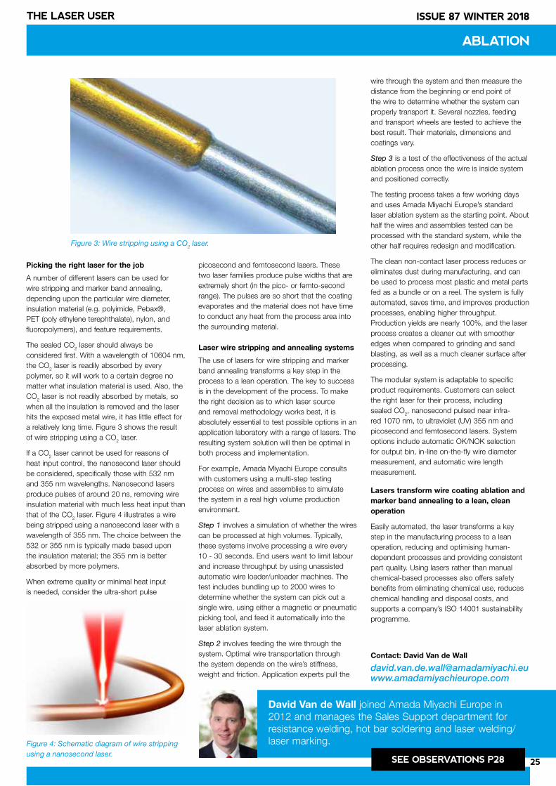
25
ISSUE 87 WINTER 2018THE LASER USER
Picking the right laser for the job
A number of different lasers can be used for wire stripping and marker band annealing, depending upon the particular wire diameter, insulation material (e.g. polyimide, Pebax®, PET (poly ethylene terephthalate), nylon, and fluoropolymers), and feature requirements.
The sealed CO2 laser should always be considered first. With a wavelength of 10604 nm, the CO2 laser is readily absorbed by every polymer, so it will work to a certain degree no matter what insulation material is used. Also, the CO2 laser is not readily absorbed by metals, so when all the insulation is removed and the laser hits the exposed metal wire, it has little effect for a relatively long time. Figure 3 shows the result of wire stripping using a CO2 laser.
If a CO2 laser cannot be used for reasons of heat input control, the nanosecond laser should be considered, specifically those with 532 nm and 355 nm wavelengths. Nanosecond lasers produce pulses of around 20 ns, removing wire insulation material with much less heat input than that of the CO2 laser. Figure 4 illustrates a wire being stripped using a nanosecond laser with a wavelength of 355 nm. The choice between the 532 or 355 nm is typically made based upon the insulation material; the 355 nm is better absorbed by more polymers.
When extreme quality or minimal heat input is needed, consider the ultra-short pulse
picosecond and femtosecond lasers. These two laser families produce pulse widths that are extremely short (in the pico- or femto-second range). The pulses are so short that the coating evaporates and the material does not have time to conduct any heat from the process area into the surrounding material.
Laser wire stripping and annealing systems
The use of lasers for wire stripping and marker band annealing transforms a key step in the process to a lean operation. The key to success is in the development of the process. To make the right decision as to which laser source and removal methodology works best, it is absolutely essential to test possible options in an application laboratory with a range of lasers. The resulting system solution will then be optimal in both process and implementation.
For example, Amada Miyachi Europe consults with customers using a multi-step testing process on wires and assemblies to simulate the system in a real high volume production environment.
Step 1 involves a simulation of whether the wires can be processed at high volumes. Typically, these systems involve processing a wire every 10 - 30 seconds. End users want to limit labour and increase throughput by using unassisted automatic wire loader/unloader machines. The test includes bundling up to 2000 wires to determine whether the system can pick out a single wire, using either a magnetic or pneumatic picking tool, and feed it automatically into the laser ablation system.
Step 2 involves feeding the wire through the system. Optimal wire transportation through the system depends on the wire’s stiffness, weight and friction. Application experts pull the
wire through the system and then measure the distance from the beginning or end point of the wire to determine whether the system can properly transport it. Several nozzles, feeding and transport wheels are tested to achieve the best result. Their materials, dimensions and coatings vary.
Step 3 is a test of the effectiveness of the actual ablation process once the wire is inside system and positioned correctly.
The testing process takes a few working days and uses Amada Miyachi Europe’s standard laser ablation system as the starting point. About half the wires and assemblies tested can be processed with the standard system, while the other half requires redesign and modification.
The clean non-contact laser process reduces or eliminates dust during manufacturing, and can be used to process most plastic and metal parts fed as a bundle or on a reel. The system is fully automated, saves time, and improves production processes, enabling higher throughput. Production yields are nearly 100%, and the laser process creates a cleaner cut with smoother edges when compared to grinding and sand blasting, as well as a much cleaner surface after processing.
The modular system is adaptable to specific product requirements. Customers can select the right laser for their process, including sealed CO2, nanosecond pulsed near infra-red 1070 nm, to ultraviolet (UV) 355 nm and picosecond and femtosecond lasers. System options include automatic OK/NOK selection for output bin, in-line on-the-fly wire diameter measurement, and automatic wire length measurement.
Lasers transform wire coating ablation and marker band annealing to a lean, clean operation
Easily automated, the laser transforms a key step in the manufacturing process to a lean operation, reducing and optimising human-dependent processes and providing consistent part quality. Using lasers rather than manual chemical-based processes also offers safety benefits from eliminating chemical use, reduces chemical handling and disposal costs, and supports a company’s ISO 14001 sustainability programme.
Contact: David Van de Wall
[email protected] www.amadamiyachieurope.com
David Van de Wall joined Amada Miyachi Europe in 2012 and manages the Sales Support department for resistance welding, hot bar soldering and laser welding/laser marking.
ABLATION
SEE OBSERVATIONS P28
Figure 3: Wire stripping using a CO2 laser.
Figure 4: Schematic diagram of wire stripping using a nanosecond laser.
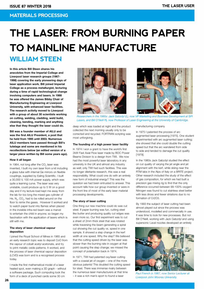
26
ISSUE 87 WINTER 2018 THE LASER USER
PRODUCT NEWS
26
THE LASER: FROM BURNING PAPER
TO MAINLINE MANUFACTURE WILLIAM STEEN
MATERIALS PROCESSING
In this article Bill Steen shares his anecdotes from the Imperial College and Liverpool laser research groups (1967-1998) covering the early pioneering days of laser application work. Bill joined Imperial College as a process metallurgist, lecturing during a time of rapid technological change involving computers and lasers. In 1988 he was offered the James Bibby Chair of Manufacturing Engineering at Liverpool University, with enhanced laser facilities. The research activity moved to Liverpool with a group of about 30 scientists working on cutting, welding, cladding, weld build, cleaning, bending, marking and anything else that they thought the laser could do.
Bill was a founder member of AILU and was the first AILU President, a post that he held from 1995 until 2003. Numerous AILU members have passed through Bill's tutelage and some are mentioned in his recollections below (an edited version of a larger piece written by Bill some years ago).
How it all began
In 1964, not long after the CO2 laser was invented, I built my own laser from a kit including a glass tube with internal Ge mirrors on flexible couplings, supplied by Ealing Scientific. I built a 30,000 V, 100 mA power supply, which was quite a learning curve. The laser was very unstable, could produce up to 5 W on a good day and if my lecture load kept me away from the lab for too long the mixed gas cylinder of He, N2, CO2, had to be rolled around on the floor to remix the gases. However it worked and to watch paper burst into flames when placed in the invisible infra-red beam was a marvel to entertain the child in anyone; so began my fascination with the application of lasers which is still with me.
The story of laser chemical vapour deposition
I joined the Royal School of Mines in 1965 and an early research topic was to deposit CoO from the vapour of cobalt acetyl acetonate, and try to print metallic oxide patterns. It worked, and the process of laser chemical vapour deposition (LCVD) was born and is a recognised process today.
I made the first mathematical model of a laser heated spot, even making a 3D graph - without a software package. Such computing took the form of a deck of punched cards some 30 cm
deep which was loaded at night and the product collected the next morning usually only to be corrected and recycled. FORTRAN scripting was most unforgiving.
The founding of a high power laser facility
In 1974 I won a grant to have the world’s first 2kW Fast Axial Flow laser made by BOC Power Beams Division to a design from TWI. We now had the most powerful laser laboratory in any university in the UK and almost any industry as well; only TWI had such facilities. This was no longer dilettante research, this was a real responsibility. What could one do with an entirely new form of industrial energy? This was the question we had been entrusted to answer. This account tells how our group invented or were in the front line of most of the early laser material processing developments.
The story of laser cutting
One thing our new machine could do was cut steel. If paper burning was fun, cutting steel like butter and producing quality cut edges was even more so. Our first experiment was to cut a sheet of 2mm thick steel that was rotated while traversing the beam generating a spiral cut showing the cut quality vs. speed in one sample. It showed a step change in the kerf width at one speed. Why the step? We believed that the cutting speed driven by the laser was slower than the burning rate in oxygen at that point causing the step change; we missed the concept of polarisation back in 1974.
In 1971, TWI had patented oxy/laser cutting with a coaxial jet of oxygen – one of the more obvious patents! This doubled the cutting speed for steel. There was immense rivalry between the numerous laser manufacturers at that time – it was a rich man’s sport to found a laser
manufacturing company.
In 1975 I patented the process of arc augmented laser processing [1975]. One student experimented with arc augmented laser cutting; she showed that she could double the cutting speed but that the arc wandered from side to side and tended to damage the cut quality [1979].
In the 1980s Jack Gabzdyl studied the effect on cut quality of varying the jet angle and jet alignment with the kerf, while skiing near the RTM labs in the Alps of Italy on a BRITE project. Other research included the study of the effect of gas composition, for which we had built a precision gas mixing rig to find that the only difference occurred between 99-100% oxygen! Nitrogen was found to cut stainless steel better with less dross and fewer striations due to no formation of Cr2O3.
By 1993 the subject of laser cutting had been almost played out since the process was understood, modelled and commercially in use. It was time to look for new processes. But no! Bill O’Neill, working with Jack Gabzdyl and using supersonic Laval nozzles developed an entirely
Researchers in the 1980s: Jack Gabzdyl (L), now VP Marketing and Business Development at SPI Lasers, and Bill O'Neill R), now Professor of Laser Engineering at the University of Cambridge.
Paul French in 1987, now Senior Lecturer at Liverpool John Moores University.
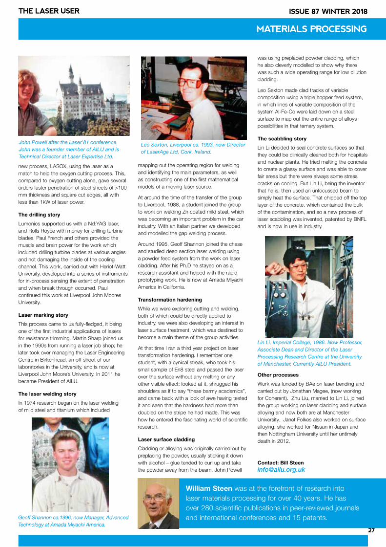
27
ISSUE 87 WINTER 2018THE LASER USER
new process, LASOX, using the laser as a match to help the oxygen cutting process. This, compared to oxygen cutting alone, gave several orders faster penetration of steel sheets of >100 mm thickness and square cut edges, all with less than 1kW of laser power.
The drilling story
Lumonics supported us with a Nd:YAG laser, and Rolls Royce with money for drilling turbine blades. Paul French and others provided the muscle and brain power for the work which included drilling turbine blades at various angles and not damaging the inside of the cooling channel. This work, carried out with Heriot-Watt University, developed into a series of instruments for in-process sensing the extent of penetration and when break through occurred. Paul continued this work at Liverpool John Moores University.
Laser marking story
This process came to us fully-fledged, it being one of the first industrial applications of lasers for resistance trimming. Martin Sharp joined us in the 1990s from running a laser job shop; he later took over managing the Laser Engineering Centre in Birkenhead, an off-shoot of our laboratories in the University, and is now at Liverpool John Moore’s University. In 2011 he became President of AILU.
The laser welding story
In 1974 research began on the laser welding of mild steel and titanium which included
mapping out the operating region for welding and identifying the main parameters, as well as constructing one of the first mathematical models of a moving laser source.
At around the time of the transfer of the group to Liverpool, 1988, a student joined the group to work on welding Zn coated mild steel, which was becoming an important problem in the car industry. With an Italian partner we developed and modelled the gap welding process.
Around 1995, Geoff Shannon joined the chase and studied deep section laser welding using a powder feed system from the work on laser cladding. After his Ph.D he stayed on as a research assistant and helped with the rapid prototyping work. He is now at Amada Miyachi America in California.
Transformation hardening
While we were exploring cutting and welding, both of which could be directly applied to industry, we were also developing an interest in laser surface treatment, which was destined to become a main theme of the group activities.
At that time I ran a third year project on laser transformation hardening. I remember one student, with a cynical streak, who took his small sample of En8 steel and passed the laser over the surface without any melting or any other visible effect; looked at it, shrugged his shoulders as if to say “these barmy academics”, and came back with a look of awe having tested it and seen that the hardness had more than doubled on the stripe he had made. This was how he entered the fascinating world of scientific research.
Laser surface cladding
Cladding or alloying was originally carried out by preplacing the powder, usually sticking it down with alcohol – glue tended to curl up and take the powder away from the beam. John Powell
was using preplaced powder cladding, which he also cleverly modelled to show why there was such a wide operating range for low dilution cladding.
Leo Sexton made clad tracks of variable composition using a triple hopper feed system, in which lines of variable composition of the system Al-Fe-Co were laid down on a steel surface to map out the entire range of alloys possibilities in that ternary system.
The scabbling story
Lin Li decided to seal concrete surfaces so that they could be clinically cleaned both for hospitals and nuclear plants. He tried melting the concrete to create a glassy surface and was able to cover fair areas but there were always some stress cracks on cooling. But Lin Li, being the inventor that he is, then used an unfocussed beam to simply heat the surface. That chipped off the top layer of the concrete, which contained the bulk of the contamination, and so a new process of laser scabbling was invented, patented by BNFL and is now in use in industry.
Other processes
Work was funded by BAe on laser bending and carried out by Jonathan Magee, (now working for Coherent). Zhu Liu, married to Lin Li, joined the group working on laser cladding and surface alloying and now both are at Manchester University. Janet Folkes also worked on surface alloying, she worked for Nissan in Japan and then Nottingham University until her untimely death in 2012.
Contact: Bill [email protected]
William Steen was at the forefront of research into laser materials processing for over 40 years. He has over 280 scientific publications in peer-reviewed journals and international conferences and 15 patents.
MATERIALS PROCESSING
Geoff Shannon ca.1996, now Manager, Advanced Technology at Amada Miyachi America.
John Powell after the Laser'81 conference. John was a founder member of AILU and is Technical Director at Laser Expertise Ltd.
Lin Li, Imperial College, 1986. Now Professor, Associate Dean and Director of the Laser Processing Research Centre at the University of Manchester. Currently AILU President.
Leo Sexton, Liverpool ca. 1993, now Director of LaserAge Ltd, Cork, Ireland.
28
ISSUE 87 WINTER 2018 THE LASER USER
OBSERVATIONS
FLUID AND PARTICLE DYNAMICS IN LASER POWDER BED FUSION Ioannis Bitharas et al.
Good to see a second paper on this topic by Heriot-Watt University and the University of Birmingham. This paper highlights the importance of finding a good process parameter to minimise the denudation effect. The high-speed images of single tracks backed up this suggestion as the direction of plume changed and created a different denudation pattern for different process parameters. I am happy to see that this work was extended to multiple tracks and for multiple layers, as single line scans do not fully represent conditions of all real-time applications.
Ravi Aswathanarayanaswamy, Renishaw
STUDY ON POWDER BLOWN LASER CLADDING OF VERTICAL SURFACES Piotr Lubaszka & Bernd Baufeld
This is an interesting article which tackles the general assumption that laser cladding cannot be used in configurations requiring significant deviations from the downhand position (1G ASME/PA ISO 6947). While it is true that laser cladding process parameters developed for cladding in the downhand positon cannot be simply transferred to other orientations, due to the effect of gravity on the powder stream and melt pool, this does not mean that appropriate parameter sets cannot be developed for such configurations. The authors have very clearly demonstrated not only the ability to develop KPV combinations which produce claddings in the horizontal (2G ASME/PC ISO 6947) position, but that the parameters can be refined to ensure that the resultant microstructure is comparable to that obtained by conventional cladding in the downhand position.
This is a very positive step in addressing what is commonly seen as one of the limitations of the laser cladding process. It would be interesting to see more work like this applied for use with mobile laser cladding equipment which can then be used for the performance of repairs to components ‘in situ’ or surface treatment of large components, as in this case in this article, which are too massive to be manipulated under the cladding head in the conventional way.
Paul Goodwin, TWI
LASER WELDING PLASTICS – A SHORT GUIDE Ian Jones
The article by Ian Jones is very well written and extremely informative in relation to the different types of laser, and the laser-welding techniques used for plastics. It also delivers a clear and concise understanding of the science behind the process.
From a production perspective however, many plastic parts will have been manufactured by injection moulding. These components can become slightly distorted during the post moulding cooling process or through improper handling prior to welding. It is essential therefore, that variations with the manufacturing processes however slight, are understood by both the product designer and the supplier of the laser welding system.
Joint design, specifically in relation to the positioning and dimensions of any joint melt/collapse area, requires careful consideration to ensure that this remains consistent. Other key factors are the design of the component fixtures and the clamping pressure to be applied during welding. Too little pressure may result in no fusion between the parts, and too much pressure could cause the weld joint above to collapse prior to the welding process commencing. Dissimilar materials may heat up at different rates, causing distortion during welding.
Andy Toms, TLM Laser
LASER SHOCK PEENING OF METALS AND ADVANCED CERAMICSPratik Shukla
As a manufacturer of high-energy nanosecond lasers, Litron has watched the Laser Shock Peening application develop with interest. For a number of years, we have been supplying custom built lasers for LSP to increase the life of components within nuclear reactors, where this application has been field-proven and successful.
In recent times we have seen a sharp increase in the research into and applications of this technique for other industrial processes in other markets worldwide, some of the key ones being additive manufacturing, automotive and aerospace component manufacture. We are eagerly anticipating a growth in the uptake of LSP once these activities progress through to manufacturing, as this process is such a good fit for the laser sources we manufacture.
James McDowell, Litron Lasers
LASER ABLATION: LAYER REMOVAL AND SURFACE TREATMENTSDavid Van De Wall
David has provided us with a useful white paper on the types of laser ablation and marking applications found in medical device manufacture. The classic application over the last twenty years has been laser stripping marker bands on guidewire and hypotube over-jackets made from PTFE coatings, using q-switched lasers at 1064 nm. As David points out selective roughening of areas of the underlying bare metal for gluing can also be performed, and with the same laser tool.
These devices are used in delivery systems for stenting blocked arteries. Many of us will know someone that has had heart stents placed and carried on an active lifestyle after this minimally invasive procedure. Laser technology plays a major role in the entire manufacture of these devices from the delivery system that deploys the stent, to the stent itself with processes in cutting, welding, marking and ablation of both polymer and metal components. As David remarks the demands on laser wire stripping processes are steadily increasing due to miniaturisation. Components such as the tiny electrodes used for brain stimulation and control in diseases like Parkinsons and Benign Essential Tremor require laser ablation often with ultrashort pulsed lasers. It is great that our industry enables so many of these lifesaving and transforming activities.
Jonathan Magee, Coherent | Rofin
LASERS FOR MANUFACTURING
ZONE
BOOK A STAND:
REDUCED RATE FOR AILU MEMBERS
CONTACT
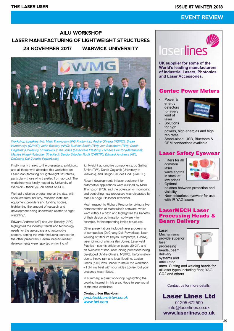
29
ISSUE 87 WINTER 2018THE LASER USER
Firstly, many thanks to the presenters, exhibitors, and all those who attended this workshop on Laser Manufacturing of Lightweight Structures, particularly those who travelled from abroad. The workshop was kindly hosted by University of Warwick – thank you on behalf of AILU.
We had a diverse programme on the day, with speakers from industry, research institutes, equipment providers and funding bodies; highlighting the amount of research and development being undertaken related to ‘light-weighting’.
Edward Andrews (ATI) and Jon Beasley (APC) highlighted the industry trends and technology needs for the aerospace and automotive sectors, setting the wider industrial context for the other presenters. Several near-to-market developments were reported on joining of
lightweight automotive components, by Sullivan Smith (TWI), Derek Ceglarek (University of Warwick), and Sergio Saludes Rodil (CARTIF).
Recent developments in laser equipment for automotive applications were outlined by Mark Thompson (IPG), and the potential for monitoring and controlling new processes was discussed by Markus Kogel-Hollacher (Precitec).
Much respect to Richard Proctor for giving a live demonstration of Materialise’s software, which went without a hitch and highlighted the benefits of their design optimisation software – for example, for incorporating lattice structures.
Other presentations included laser processing of composites (DeChang Dai, Powerlase), laser welding of titanium (Bryan Humphreys, CAVAT), laser joining of plastics (Ian Jones, Laserweld Plastics - see his article on pages 20-21), and an overview of non-laser joining processes being developed (Andre Oliveira, NSIRC). Unfortunately, due to heavy rain and local flooding, Louise Jones (KTN) was unable to make the workshop – I did my best with your slides Louise, but your presence was missed.
In summary, a great workshop highlighting the growing interest in this area. Hope to see you all at the next workshop.
Contact: Jon [email protected]
EVENT REVIEW
AILU WORKSHOP
LASER MANUFACTURING OF LIGHTWEIGHT STRUCTURES
23 NOVEMBER 2017 WARWICK UNIVERSITY
Workshop speakers (l-r): Mark Thompson (IPG Photonics); Andre Oliveira (NSIRC); Bryan Humphreys (CAVAT); John Beasley (APC); Sullivan Smith (TWI); Jon Blackburn (TWI); Darek Ceglarek (University of Warwick ); Ian Jones (Laserweld Plastics); Richard Proctor (Materialise); Markus Kogel-Hollacher (Precitec); Sergio Saludes Rodil (CARTIF); Edward Andrews (ATI); DeChang Dai (Andritz PowerLase).
Gentec Power Meters
Contact us for more details:
Laser Lines Ltd01295 672500
www.laserlines.co.uk
Laser Safety Eyewear
LaserMECH LaserProcessing Heads & Beam Delivery
Power & energy detectors for every kind of laser
Solutions for high powers, high energies and high rep rates
Stand-alone, USB, Bluetooth & OEM connections available
Filters for all common laser wavelengths in stock at low prices
Optimal balance between protection and visibility
New colourless eyewear for use with IR YAG lasers
Laser Mechanisms provide superior laser processing heads, beam delivery systems and articulated arms. Cutting and welding heads for all laser types including fiber, YAG, CO2 and others
UK supplier for some of the World’s leading manufacturers of Industrial Lasers, Photonics and Laser Accessories.
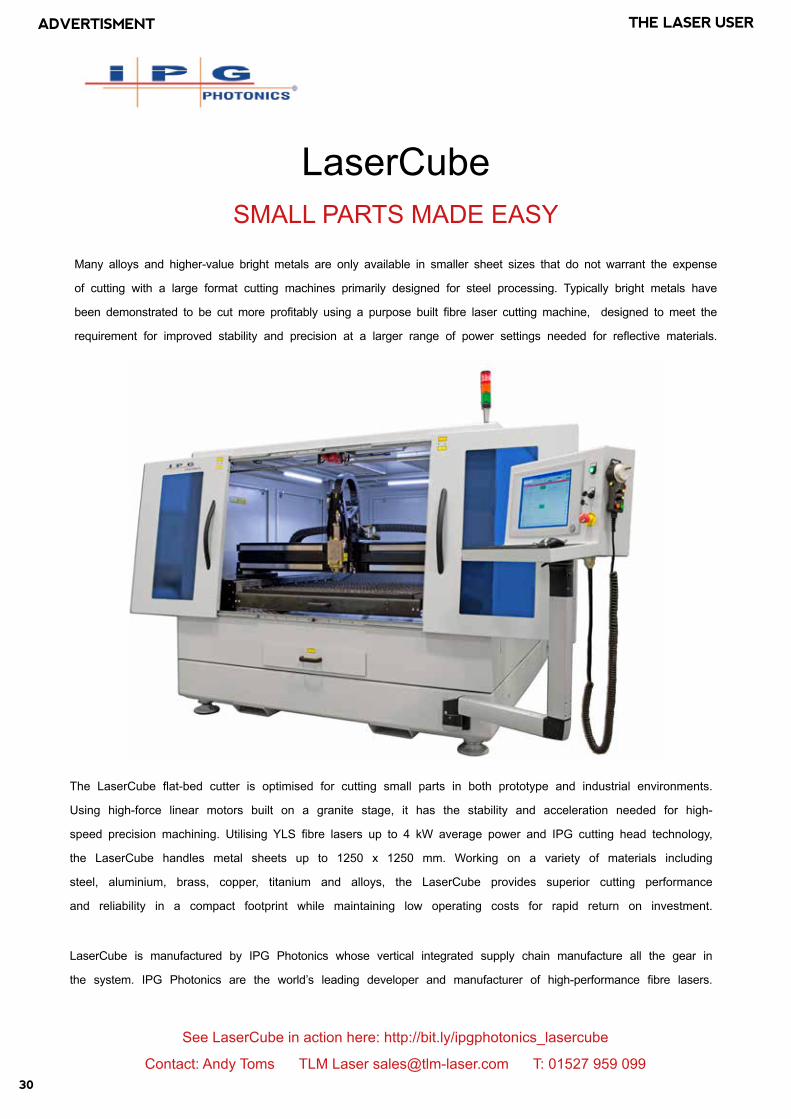
30
ISSUE 87 WINTER 2018 THE LASER USERADVERTISMENT
LaserCube SMALL PARTS MADE EASY
Many alloys and higher-value bright metals are only available in smaller sheet sizes that do not warrant the expense
of cutting with a large format cutting machines primarily designed for steel processing. Typically bright metals have
been demonstrated to be cut more profitably using a purpose built fibre laser cutting machine, designed to meet the
requirement for improved stability and precision at a larger range of power settings needed for reflective materials.
The LaserCube flat-bed cutter is optimised for cutting small parts in both prototype and industrial environments.
Using high-force linear motors built on a granite stage, it has the stability and acceleration needed for high-
speed precision machining. Utilising YLS fibre lasers up to 4 kW average power and IPG cutting head technology,
the LaserCube handles metal sheets up to 1250 x 1250 mm. Working on a variety of materials including
steel, aluminium, brass, copper, titanium and alloys, the LaserCube provides superior cutting performance
and reliability in a compact footprint while maintaining low operating costs for rapid return on investment.
LaserCube is manufactured by IPG Photonics whose vertical integrated supply chain manufacture all the gear in
the system. IPG Photonics are the world’s leading developer and manufacturer of high-performance fibre lasers.
See LaserCube in action here: http://bit.ly/ipgphotonics_lasercube
Contact: Andy Toms TLM Laser [email protected] T: 01527 959 099
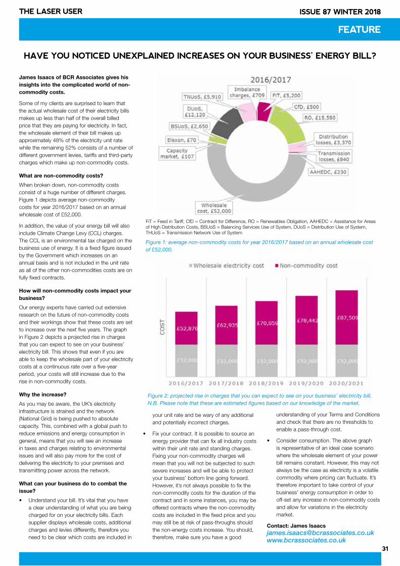
31
ISSUE 87 WINTER 2018THE LASER USER
James Isaacs of BCR Associates gives his insights into the complicated world of non-commodity costs.
Some of my clients are surprised to learn that the actual wholesale cost of their electricity bills makes up less than half of the overall billed price that they are paying for electricity. In fact, the wholesale element of their bill makes up approximately 48% of the electricity unit rate while the remaining 52% consists of a number of different government levies, tariffs and third-party charges which make up non-commodity costs.
What are non-commodity costs?
When broken down, non-commodity costs consist of a huge number of different charges. Figure 1 depicts average non-commodity costs for year 2016/2017 based on an annual wholesale cost of £52,000.
In addition, the value of your energy bill will also include Climate Change Levy (CCL) charges. The CCL is an environmental tax charged on the business use of energy. It is a fixed figure issued by the Government which increases on an annual basis and is not included in the unit rate as all of the other non-commodities costs are on fully fixed contracts.
How will non-commodity costs impact your business?
Our energy experts have carried out extensive research on the future of non-commodity costs and their workings show that these costs are set to increase over the next five years. The graph in Figure 2 depicts a projected rise in charges that you can expect to see on your business’ electricity bill. This shows that even if you are able to keep the wholesale part of your electricity costs at a continuous rate over a five-year period, your costs will still increase due to the rise in non-commodity costs.
Why the increase?
As you may be aware, the UK’s electricity infrastructure is strained and the network (National Grid) is being pushed to absolute capacity. This, combined with a global push to reduce emissions and energy consumption in general, means that you will see an increase in taxes and charges relating to environmental issues and will also pay more for the cost of delivering the electricity to your premises and transmitting power across the network.
What can your business do to combat the issue?
• Understand your bill. It’s vital that you have a clear understanding of what you are being charged for on your electricity bills. Each supplier displays wholesale costs, additional charges and levies differently, therefore you need to be clear which costs are included in
your unit rate and be wary of any additional and potentially incorrect charges.
• Fix your contract. It is possible to source an energy provider that can fix all industry costs within their unit rate and standing charges. Fixing your non-commodity charges will mean that you will not be subjected to such severe increases and will be able to protect your business’ bottom line going forward. However, it’s not always possible to fix the non-commodity costs for the duration of the contract and in some instances, you may be offered contracts where the non-commodity costs are included in the fixed price and you may still be at risk of pass-throughs should the non-energy costs increase. You should, therefore, make sure you have a good
understanding of your Terms and Conditions and check that there are no thresholds to enable a pass-through cost.
• Consider consumption. The above graph is representative of an ideal case scenario where the wholesale element of your power bill remains constant. However, this may not always be the case as electricity is a volatile commodity where pricing can fluctuate. It’s therefore important to take control of your business’ energy consumption in order to off-set any increase in non-commodity costs and allow for variations in the electricity market.
Contact: James [email protected]
FEATURE
HAVE YOU NOTICED UNEXPLAINED INCREASES ON YOUR BUSINESS’ ENERGY BILL?
Figure 1: average non-commodity costs for year 2016/2017 based on an annual wholesale cost of £52,000.
Figure 2: projected rise in charges that you can expect to see on your business’ electricity bill. N.B. Please note that these are estimated figures based on our knowledge of the market.
FiT = Feed in Tariff, CfD = Contract for Difference, RO = Renewables Obligation, AAHEDC = Assistance for Areas of High Distribution Costs, BSUoS = Balancing Services Use of System, DUoS = Distribution Use of System, THUoS = Transmission Network Use of System
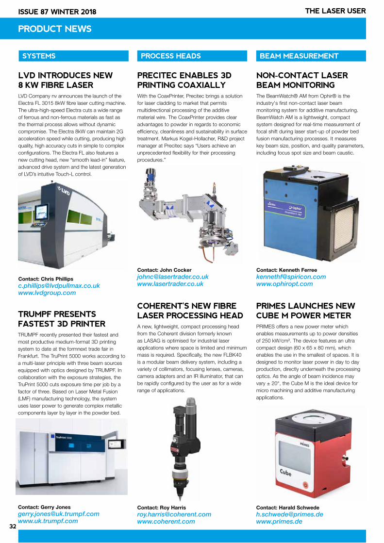
32
ISSUE 87 WINTER 2018 THE LASER USER
PRODUCT NEWS
COHERENT'S NEW FIBRE LASER PROCESSING HEADA new, lightweight, compact processing head from the Coherent division formerly known as LASAG is optimised for industrial laser applications where space is limited and minimum mass is required. Specifically, the new FLBK40 is a modular beam delivery system, including a variety of collimators, focusing lenses, cameras, camera adapters and an IR illuminator, that can be rapidly configured by the user as for a wide range of applications.
Contact: Roy [email protected]
NON-CONTACT LASER BEAM MONITORINGThe BeamWatch® AM from Ophir® is the industry's first non-contact laser beam monitoring system for additive manufacturing. BeamWatch AM is a lightweight, compact system designed for real-time measurement of focal shift during laser start-up of powder bed fusion manufacturing processes. It measures key beam size, position, and quality parameters, including focus spot size and beam caustic.
Contact: Kenneth [email protected]
PRIMES LAUNCHES NEW CUBE M POWER METERPRIMES offers a new power meter which enables measurements up to power densities of 250 kW/cm². The device features an ultra compact design (60 x 65 x 80 mm), which enables the use in the smallest of spaces. It is designed to monitor laser power in day to day production, directly underneath the processing optics. As the angle of beam incidence may vary ± 20°, the Cube M is the ideal device for micro machining and additive manufacturing applications.
Contact: Harald [email protected]
LVD INTRODUCES NEW 8 KW FIBRE LASER LVD Company nv announces the launch of the Electra FL 3015 8kW fibre laser cutting machine. The ultra-high-speed Electra cuts a wide range of ferrous and non-ferrous materials as fast as the thermal process allows without dynamic compromise. The Electra 8kW can maintain 2G acceleration speed while cutting, producing high quality, high accuracy cuts in simple to complex configurations. The Electra FL also features a new cutting head, new “smooth lead-in” feature, advanced drive system and the latest generation of LVD’s intuitive Touch-L control.
Contact: Chris [email protected]
TRUMPF PRESENTS FASTEST 3D PRINTERTRUMPF recently presented their fastest and most productive medium-format 3D printing system to date at the formnext trade fair in Frankfurt. The TruPrint 5000 works according to a multi-laser principle with three beam sources equipped with optics designed by TRUMPF. In collaboration with the exposure strategies, the TruPrint 5000 cuts exposure time per job by a factor of three. Based on Laser Metal Fusion (LMF) manufacturing technology, the system uses laser power to generate complex metallic components layer by layer in the powder bed.
Contact: Gerry [email protected]
PRECITEC ENABLES 3D PRINTING COAXIALLYWith the CoaxPrinter, Precitec brings a solution for laser cladding to market that permits multidirectional processing of the additive material wire. The CoaxPrinter provides clear advantages to powder in regards to economic efficiency, cleanliness and sustainability in surface treatment. Markus Kogel-Hollacher, R&D project manager at Precitec says “Users achieve an unprecedented flexibility for their processing procedures.”
Contact: John [email protected]
SYSTEMS PROCESS HEADS BEAM MEASUREMENT
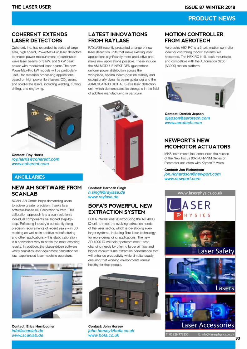
33
ISSUE 87 WINTER 2018THE LASER USER
PRODUCT NEWS
ANCILLARIES
BOFA'S POWERFUL NEW EXTRACTION SYSTEMBOFA International is introducing the AD 4000 iQ unit to meet the evolving extraction needs of the laser sector, which is developing ever-larger systems, including fibre-laser technology for more demanding applications. The new AD 4000 iQ will help operators meet these changing needs by offering larger air flow and higher vacuum fume extraction performance that will enhance productivity while simultaneously ensuring that working environments remain healthy for their people.
Contact: John Horsey [email protected]
NEW AM SOFTWARE FROM SCANLABSCANLAB GmbH helps demanding users to acieve greater precision, thanks to a software-based 3D Calibration Wizard. This calibration approach lets a scan solution's individual components be aligned step-by-step. Reflecting industry's constantly rising precision requirements of recent years – in 3D marking as well as in additive manufacturing and other applications – this static calibration is a convenient way to attain the most exacting results. In addition, the dialog-driven software vastly simplifies laser equipment calibration for less-experienced laser machine operators.
Contact: Erica [email protected]
COHERENT EXTENDS LASER DETECTORSCoherent, Inc. has extended its series of large area, high speed, PowerMax-Pro laser detectors to enable power measurement of continuous-wave laser beams of 3 kW, and 5 kW peak power with modulated laser beams.The new PowerMax-Pro kW models will be particularly useful for materials processing applications based on high power fibre lasers, CO2 lasers, and solid-state lasers, including welding, cutting, drilling, and engraving.
Contact: Roy [email protected]
LATEST INNOVATIONS FROM RAYLASERAYLASE recently presented a range of new laser deflection units that make existing laser applications significantly more productive and make new applications possible. These include the AM-MODULE NEXT GEN (guarantees uniform power distribution across the workpiece, optimal beam position stability and exceptionally dynamic beam guidance) and the AXIALSCAN-30 DIGITAL 3-axis laser deflection unit, which demonstrates its strengths in the field of additive manufacturing in particular.
Contact: Harnesh [email protected]
MOTION CONTROLLER FROM AEROTECHAerotech’s HEX RC is a 6-axis motion controller ideal for controlling robotic systems like hexapods. The HEX RC is 4U rack-mountable and compatible with the Automation 3200 (A3200) motion platform.
Contact: Derrick [email protected]
Laser Safety
Lasers
Laser Accessories
www.laserphysics.co.uk
T: 01829 773155 E: [email protected]
NEWPORT'S NEW PICOMOTOR ACTUATORSMKS Instruments Inc. announces the release of the New Focus 83xx-UHV-NM Series of Picomotor actuators with Kapton™ wires.
Contact: Jon [email protected]
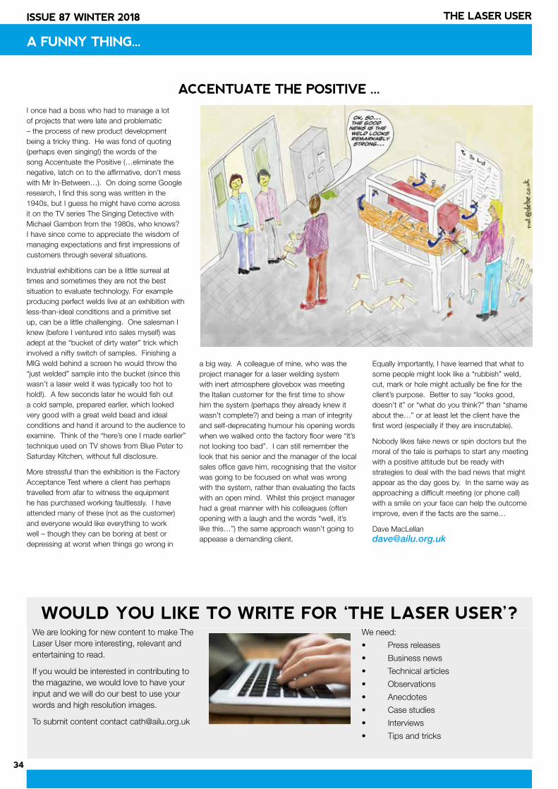
34
ISSUE 87 WINTER 2018 THE LASER USER
A FUNNY THING...
I once had a boss who had to manage a lot of projects that were late and problematic – the process of new product development being a tricky thing. He was fond of quoting (perhaps even singing!) the words of the song Accentuate the Positive (…eliminate the negative, latch on to the affirmative, don’t mess with Mr In-Between…). On doing some Google research, I find this song was written in the 1940s, but I guess he might have come across it on the TV series The Singing Detective with Michael Gambon from the 1980s, who knows? I have since come to appreciate the wisdom of managing expectations and first impressions of customers through several situations.
Industrial exhibitions can be a little surreal at times and sometimes they are not the best situation to evaluate technology. For example producing perfect welds live at an exhibition with less-than-ideal conditions and a primitive set up, can be a little challenging. One salesman I knew (before I ventured into sales myself) was adept at the “bucket of dirty water” trick which involved a nifty switch of samples. Finishing a MIG weld behind a screen he would throw the “just welded” sample into the bucket (since this wasn’t a laser weld it was typically too hot to hold!). A few seconds later he would fish out a cold sample, prepared earlier, which looked very good with a great weld bead and ideal conditions and hand it around to the audience to examine. Think of the “here’s one I made earlier” technique used on TV shows from Blue Peter to Saturday Kitchen, without full disclosure.
More stressful than the exhibition is the Factory Acceptance Test where a client has perhaps travelled from afar to witness the equipment he has purchased working faultlessly. I have attended many of these (not as the customer) and everyone would like everything to work well – though they can be boring at best or depressing at worst when things go wrong in
a big way. A colleague of mine, who was the project manager for a laser welding system with inert atmosphere glovebox was meeting the Italian customer for the first time to show him the system (perhaps they already knew it wasn’t complete?) and being a man of integrity and self-deprecating humour his opening words when we walked onto the factory floor were “it’s not looking too bad”. I can still remember the look that his senior and the manager of the local sales office gave him, recognising that the visitor was going to be focused on what was wrong with the system, rather than evaluating the facts with an open mind. Whilst this project manager had a great manner with his colleagues (often opening with a laugh and the words “well, it’s like this…”) the same approach wasn’t going to appease a demanding client.
Equally importantly, I have learned that what to some people might look like a “rubbish” weld, cut, mark or hole might actually be fine for the client’s purpose. Better to say “looks good, doesn’t it” or “what do you think?” than “shame about the…” or at least let the client have the first word (especially if they are inscrutable).
Nobody likes fake news or spin doctors but the moral of the tale is perhaps to start any meeting with a positive attitude but be ready with strategies to deal with the bad news that might appear as the day goes by. In the same way as approaching a difficult meeting (or phone call) with a smile on your face can help the outcome improve, even if the facts are the same…
Dave MacLellan [email protected]
ACCENTUATE THE POSITIVE ...
We are looking for new content to make The Laser User more interesting, relevant and entertaining to read.
If you would be interested in contributing to the magazine, we would love to have your input and we will do our best to use your words and high resolution images.
To submit content contact [email protected]
We need:
• Press releases
• Business news
• Technical articles
• Observations
• Anecdotes
• Case studies
• Interviews
• Tips and tricks
WOULD YOU LIKE TO WRITE FOR ‘THE LASER USER’?
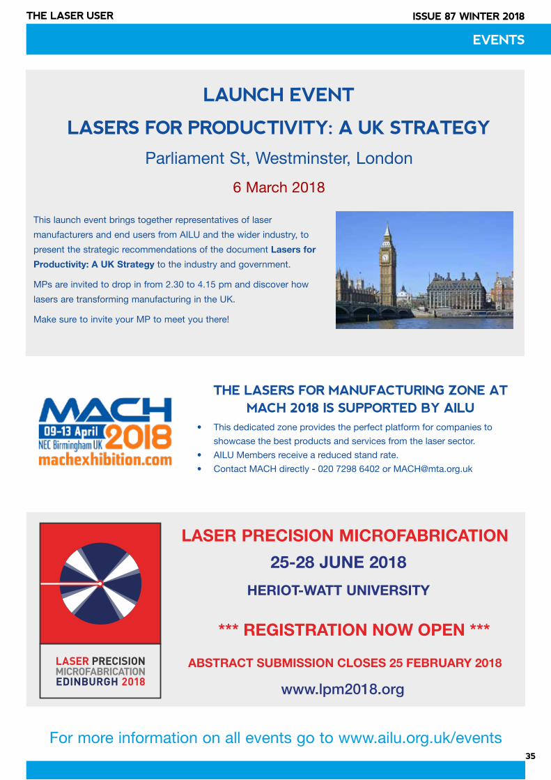
35
ISSUE 87 WINTER 2018THE LASER USER
EVENTS
LAUNCH EVENT
LASERS FOR PRODUCTIVITY: A UK STRATEGY
Parliament St, Westminster, London
6 March 2018
This launch event brings together representatives of laser
manufacturers and end users from AILU and the wider industry, to
present the strategic recommendations of the document Lasers for
Productivity: A UK Strategy to the industry and government.
MPs are invited to drop in from 2.30 to 4.15 pm and discover how
lasers are transforming manufacturing in the UK.
Make sure to invite your MP to meet you there!
LASER PRECISION MICROFABRICATION
www.lpm2018.org
LASER PRECISIONMICROFABRICATIONEDINBURGH 2018
ABSTRACT SUBMISSION CLOSES 25 FEBRUARY 2018
For more information on all events go to www.ailu.org.uk/events
THE LASERS FOR MANUFACTURING ZONE AT MACH 2018 IS SUPPORTED BY AILU
• This dedicated zone provides the perfect platform for companies to
showcase the best products and services from the laser sector.
• AILU Members receive a reduced stand rate.
• Contact MACH directly - 020 7298 6402 or [email protected]
*** REGISTRATION NOW OPEN ***
25-28 JUNE 2018
HERIOT-WATT UNIVERSITY
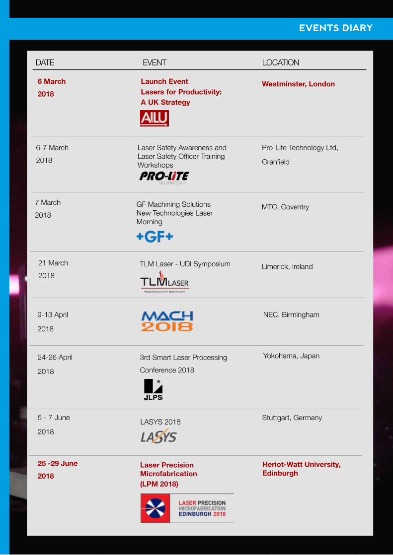
36
ISSUE 87 WINTER 2018 THE LASER USER
EVENTS DIARY
24-26 April
2018
3rd Smart Laser Processing
Conference 2018
Yokohama, Japan
9-13 April
2018
NEC, Birmingham
5 - 7 June
2018LASYS 2018 Stuttgart, Germany
25 -29 June
2018
Laser Precision Microfabrication (LPM 2018)
Heriot-Watt University, Edinburgh
DATE EVENT LOCATION
7 March
2018
GF Machining Solutions New Technologies Laser Morning
MTC, Coventry
6 March
2018
Launch EventLasers for Productivity: A UK Strategy
Westminster, London
6-7 March
2018
Laser Safety Awareness and Laser Safety Officer Training Workshops
Pro-Lite Technology Ltd,
Cranfield
21 March
2018
TLM Laser - UDI Symposium Limerick, Ireland