Embed Size (px)
Citation preview

THE LARRABEE WAY TO A BETTER PROPELLERBy Reg Boor
An Article printed in the October 1990 issue of Aero Modeller
In the March 1990 issue of Aeromodeller, Dave Hipperson, in describing his latest Coupe d'hiver model Pure Fantasy, enthused about the Larrabee propeller blade-form and the increase in efficiency that he had obtained by its use. Dave, very rightly, connected my name with that of John O'Donnell in the development and use of the Larrabee propeller, for although I had originated a design method for aeromodellers it bas been John who has used them consistently and indeed has interested the author in this article.
The method was described during the SMAE Free-Flight Experts' Forum at the 1986 Model Engineer Exhibition but that presentation was extremely mathematical and I'm afraid must have left the modellers somewhat shell-shocked and confused about the advantages of these propellers.
This time we shall steer clear of any mathematics and give instead a description of the principles involved followed by a method of designing a Larrabee-like propeller blade. But first of all, some background.
Powerhouses and propellersThe story starts in 1979 when the September issue of Aeromodeller printed a first-class report on the crossing of the English Channel by Paul. McCready's man-powered aircraft Gossamer Albatross. My opinion is that this feat ranks equally with any in the history of aviation in terms of technical achievement and I would urge all aeromodellers to read a book on the subject called Gossamer Oddessey by Morton Grosser.
But we are digressing. In the Aeromodeller article the powerhouse and pilot of Gossamer Albatross, Bryan Allen, was reported to have said that the feat would not have been possible without the propeller designed by Professor Eugene Larrabee of The Massachusetts Institute of Technology. Now, despite. having worked in aerodynamics for many years I had never seen a really theoretical method of propeller design. It seemed to be based on experience and what had been done before, although this situation is changing now that very powerful computers are available.
Intrigued, and being fortunate enough to have had an excellent technical library at my place of work, I eventually found the proceedings of a conference held by the American National Aeronautical and Space Agency (NASA report CP 2085) on the subject of low speed and motorless flight. In these proceedings was a paper by Professor Larrabee describing the complete theory of his new and unique approach to the design of propellers for low-powered flying machines such as motor gliders and man-powered aircraft.

Theory — and to the pointYou all know broadly what is meant by the wing lift coefficient. Now, each narrow chord-wise slice of a wing lift coefficient of a wing in the direction of the airflow has a ‘local’ lift coefficient and the addition of all these local lift coefficients (or integration, in mathematical jargon) makes up what we know as the wing lift-coefficient.
You all know also that an elliptic wing produces less induced drag than any other planform. Actually, we, should say that an elliptically loaded wing produces less induced drag than any other loading. What do we mean by this and why does it minimize the induced drag? If, right across the span of a wing, you multiply the local chord length by the local lift coefficient that it is carrying and if, when you plot a graph of the result it is elliptical, you have elliptic loading and that wing will have minimum induced drag. So the wing doesn’t need to be elliptical in planform; the result can be obtained using a suitable combination of planform, twist and aerofoil camber by playing off local chord against local lift coefficient.
Such a wing has minimum induced drag because, in aerodynamic jargon, the downwash along the trailing edge is constant. This minimizes the strength of the trailing edge vortex system which is cast off any wing and hence minimizes the power required to drive the wing through the air.
Now, to the point at last. A propeller is nothing more than a wing. Professor Larrabee sought a way of achieving for the propeller this ideal of minimum induced loss so as to maximize the efficiency for a given power input. But a propeller, of course, is a very complex wing. Each local chord is traveling at a different speed to its neighbor because of the rotational velocity and the blade has to be twisted helically to keep the blade incidence constant. Also, the trailing vortex system consists of a pair of intermeshed helicoidal vortex sheets, one from each blade, which mutually affect each other as the now develops. So the problem that Larrabee faced was very complex one, not easily put into words and he adapted the work of some of the worlds most famous aerodynamicists to solve it"
In the case of a propeller it is the displacement velocity which is required to be constant along the blade radius. This is the apparent speed with which the helicoidal vortex sheet moves downstream. You can get an idea of displacement velocity by twiddling a woodscrew in your fingers. If the screw is held by the head between the right finger and thumb and rotated rapidly, the screw thread appears to move towards the head. Actually, nothing moves axially, it is a phenomenon of the helical thread form and the rotational velocity.
Additionally, that mysterious quantity, the 'slip', which is related to the displacement velocity, bas to be calculated. You can get an idea of what slip is by the difference between screwing a screw into wood and then into modeling clay. In the first case the screw moves into the wood by its geometric pitch at each rotation. In the second. some of the clay is forced back by the pressure of the
screw so that it no longer moves as far on each rotation. This is the slip and is what a propeller does to the air.
Professor Larrabee's method needs to know the power of the engine, the flight conditions to be optimized and the local aerodynamic characteristics of the blade aerofoil sections. It then goes through an iterative, that is, a constantly recalculating, procedure to design a propeller of minimum, induced loss to suit the conditions. Not a promising situation for even the most enthusiastic aeromodeller
knowing, as he does, very little about any of these things.
An aeromodelling solutionSearching for a method of applying the theory in a simple way, it struck me that the aeromodeller, for all the major competition classes, has by long experience already optimized the power side of the equation by his choice of pitch to diameter (P/D) ratio and propeller size. Roughly a P/D of 1.2 for Wakefield, a P/D of about 2.0 for EZB and so on through the classes with only minor variations. Would it be possible to substitute the P/D ratio into one of Larrabee's equations and obtain Larrabee-like blade planforms?
By making some sweeping approximations, which amounted to assuming that the design criteria had already been met, this was done and sure enough I did obtain similar blade planforms but, of course, because my equations did not take account of the power these blades were of no particular size. John O'Donnell came to my rescue with a paper by the Professor in which, by making assumptions about the rubber power, he had designed a Wakefield propeller. Putting the P/D ratio from the paper into my method I was delighted to discover that by assuming 12.5 percent slip and simply scaling to the same radius and maximum blade width my propeller was the same planform as the Professor's.
If you look at Figure 1 you will see an illustration of how the blade planform changes for four values of P/D ratio using this approach. Notice that the maximum blade width is between about a quarter and a half of the distance between shaft and tip. The old 'wing shovel' planform that aeromodellers used to employ was not efficient. It may have absorbed the power but this, knowing what we do now should. be done by a blade wider, nearer the shaft.
The same is true of full-size propellers, as Larrabee points out. Early propellers of the 1930 and 1940 eras had such blade forms; it was only with the advent of very high power piston engines that crude rectangular bladed propellers were used, simply as the easiest way to absorb the power.
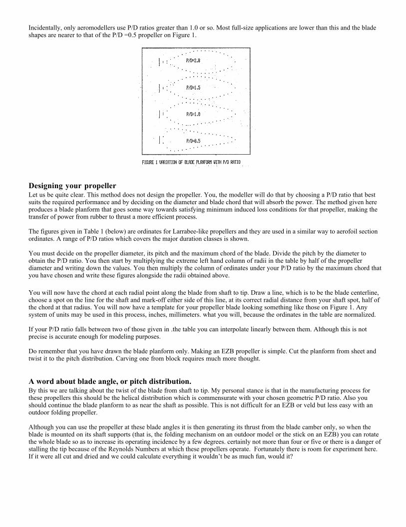
Incidentally, only aeromodellers use P/D ratios greater than 1.0 or so. Most full-size applications are lower than this and the blade shapes are nearer to that of the P/D =0.5 propeller on Figure 1.
Designing your propellerLet us be quite clear. This method does not design the propeller. You, the modeller will do that by choosing a P/D ratio that best suits the required performance and by deciding on the diameter and blade chord that will absorb the power. The method given here produces a blade planform that goes some way towards satisfying minimum induced loss conditions for that propeller, making the transfer of power from rubber to thrust a more efficient process.
The figures given in Table 1 (below) are ordinates for Larrabee-like propellers and they are used in a similar way to aerofoil section ordinates. A range of P/D ratios which covers the major duration classes is shown.
You must decide on the propeller diameter, its pitch and the maximum chord of the blade. Divide the pitch by the diameter to obtain the P/D ratio. You then start by multiplying the extreme left hand column of radii in the table by half of the propeller diameter and writing down the values. You then multiply the column of ordinates under your P/D ratio by the maximum chord that you have chosen and write these figures alongside the radii obtained above.
You will now have the chord at each radial point along the blade from shaft to tip. Draw a line, which is to be the blade centerline, choose a spot on the line for the shaft and mark-off either side of this line, at its correct radial distance from your shaft spot, half of the chord at that radius. You will now have a template for your propeller blade looking something like those on Figure 1. Any system of units may be used in this process, inches, millimeters. what you will, because the ordinates in the table are normalized.
If your P/D ratio falls between two of those given in .the table you can interpolate linearly between them. Although this is not precise is accurate enough for modeling purposes.
Do remember that you have drawn the blade planform only. Making an EZB propeller is simple. Cut the planform from sheet and twist it to the pitch distribution. Carving one from block requires much more thought.
A word about blade angle, or pitch distribution.By this we are talking about the twist of the blade from shaft to tip. My personal stance is that in the manufacturing process for these propellers this should be the helical distribution which is commensurate with your chosen geometric P/D ratio. Also you should continue the blade planform to as near the shaft as possible. This is not difficult for an EZB or veld but less easy with an outdoor folding propeller.
Although you can use the propeller at these blade angles it is then generating its thrust from the blade camber only, so when the blade is mounted on its shaft supports (that is, the folding mechanism on an outdoor model or the stick on an EZB) you can rotate the whole blade so as to increase its operating incidence by a few degrees. certainly not more than four or five or there is a danger of stalling the tip because of the Reynolds Numbers at which these propellers operate. Fortunately there is room for experiment here. If it were all cut and dried and we could calculate everything it wouldn’t be as much fun, would it?


![HUMAN POWER - · PDF fileContributions to Human Power ... on optimal propeller design [1], [2]. Larrabee designed two ... and to design propellers myself. Larrabee’s minimum](https://img.pdfslide.us/doc/110x75/5ab791e47f8b9a28468bb635/human-power-to-human-power-on-optimal-propeller-design-1-2-larrabee.jpg)