Embed Size (px)
Citation preview
THE JOURNAL OF RADIO RESEARCH & PROGRESS
Make a Point.. of
contacting
Ediswan
They make a very large
If you require a special
type of valve when de-
signing electronic equip-
ment you would be well
advised to make a point
of consulting Ediswan.
range of Ediswan Mazda
special purpose valves and in addition have developed
an equally wide variety of Ediswan Industrial and
Transmitting types. It is more than likely that they
make the type of valve you need.
E DI SWAN MAZDA
Valves .for special purposes
The Edison Swan Electric Company, Ltd. 155 Charing Cross Road, W.C.2.
Member of the A.E.I. Group of Companies.
RV 79
II W IRELESS ENGINEER, JUNE 1952

AlTARIAC voltage regulat" d iT de Mark transformers
' VARIAC ' — the original continuously-
adjustable auto-transformer — is the ideal
device for controlling any a.c. operated
equipment. VARIA.CS not only supply per-
fectly smooth control of voltage from zero,
but on some patterns, there is even an
"over voltage" feature. Illustration left
shows the type 200 C.U.H. `VARIAC.'
Left: Type 50-8 ' VAR1AC'
Right Type 100-R ' VARIAC'
SERIES 200 «VARIAC' TRANSFORMERS
SPECIFICATIONS
Tyr* ,
LOAD RATING
INPUT VOLTAGE
CURRENT Otrreur VOLTAGE
NO-LOAD Loss
NET PRICE £ s. d. * RATED MAXIMUM
200-CM } 200-CU
200-CMH } 200-CUH
860 va.
580 va.
L15 v.
230 v. 115 v.
5 a.
2 a. 0.5 a.
7.5 a.
2.5 a. 2.5 a.
0-135 v.
0-270 v. 0-270 v.
15 watts
20 watts 20 watts
7 17 6 6150 •
915 0 8 5 4
' All ' VARIAC' prices plus 20% as from 23rd Feb. 1952
Full details of this and other models in the VARIAC' range are
contained in Catalogue V549, which will gladly be sent on request.
CLAUDE LYONS LIMITED ELECTRICAL & RADIO LABORATORY APPARATUS, ETC.
180 Tottenham Court Road, London, W.I; and 76 Oldhall Street, Liverpool, 3, Lancs.
WIRELESS E NGINEER, JUNE 1952
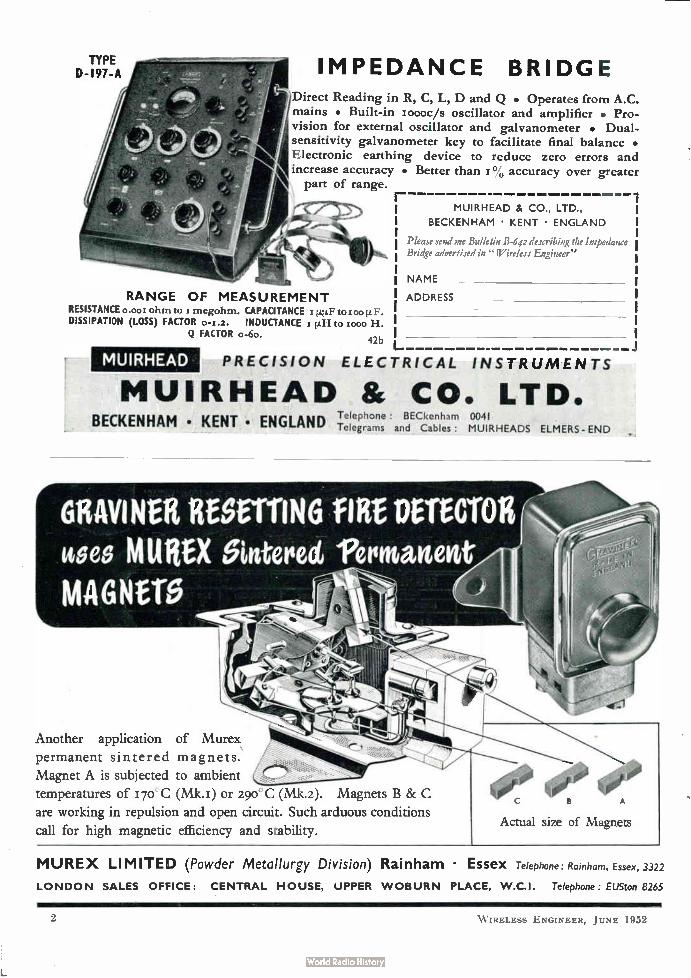
IMPEDANCE BRIDGE ¡ Direct Reading in R, C, L, D and Q • Operates from A.C.
mains • Built-in x000c/s oscillator and amplifier • Pro-
vision for external oscillator and galvanometer • Dual-sensitivity galvanometer key to facilitate final balance • Electronic earthing device to reduce zero errors and increase accuracy • Better than r °/0 accuracy over greater
part of range.
RANGE OF MEASUREMENT RESISTANCE o.00t ohmio xmegohm. CAPACITANCE r ¡Leto roo DISSIPATION (LOSS) FACTOR 0-1.2. INDUCTANCE s £1-1 to z000 H.
Q FACTOR o-6o. 42b
MUIRHEAD
MUIRHEAD & CO., LTD.,
BECKENHAM • KENT • ENGLAND I
Please send me Bulletin B-642 describing the Impedance Bridge advertised in "Wireless Engineer"
NAME
ADDRESS
PRECISION ELECTRICAL INSTRUMENTS
MUIRHEAD fic CO. LTD. Telephone : BECkenham 0041
BECKENHAM • KENT • ENGLAND Telegrams and Cables: MUIRHEADS ELMERS - END
GRAVINER userriNG flat DETECTOR uses KittleX gin-tend) 12etintdarten MAGNerb
Another application of Murex
permanent sintered magnets.
Magnet A is subjected to ambient
temperatures of I7e-C (Mk.i) or 290°C (Mk.2). Magnets B & C
are working in repulsion and open circuit. Such arduous conditions
call for high magnetic efficiency and stability.
esee Actual size of Magnets
MUREX LIMITED (Powder Metallurgy Division) Rainham • Essex Telephone: Rainham, Essex, 3322
LONDON SALES OFFICE: CENTRAL HOUSE, UPPER WOBURN PLACE, W.C.I. Telephone: EUSton 8265
W IRELESS ENGINEER, JUNE 1952
ta Çe , fête Weenee/e• • •
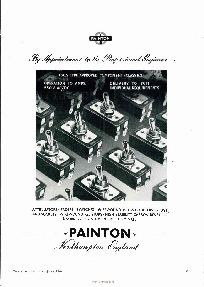
I.S.C.S TYPE APPROVED COMPON ENT (CLASS H.2)
OPERATION 10 AM PS. DELIVERY TO SUIT
250 V. AC/DC INDIVIDUAL REQUIREMENTS
ATTENUATORS • FADERS • SWITCHES • WIREWOUND POTENTIOMETERS • PLUGS .
AND SOCKETS • WIREWOUND RESISTORS • HIGH STABILITY CARBON RESISTORS
KNOBS DIALS AND POINTERS • TERMINALS
PAINTON
W IRELESS ENGINEER, JUNE 1952
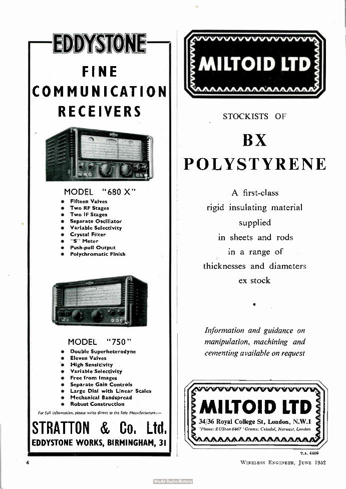
EIVYMON FINE
COMMUNICATION
RECEIVERS
MODEL "680 X" • Fifteen Valves
• Two RF Stages
• Two IF Stages
• Separate Oscillator
• Variable Selectivity
• Crystal Filter
• "S" Meter
• Push-pull Output
• Polychromatic Finish
MODEL "750" • Double Superheterodyne
• Eleven Valves
• High Sensitivity
• Variable Selectivity
• Free from Images
• Separate Gain Controls
• Large Dial with Linear Scales
• Mechanical Bandspread
• Robust Construction
For full information, please write direct to the Sole Manufacturers:—
STRATTON eic, Co. Ltd EDDYSTONE WORKS, BIRMINGHAM, 31
STOCKISTS OF
BX
POLYSTYRENE
A first-class
rigid insulating material
supplied
in sheets and rods
in a range of
thicknesses and diameters
ex stock
luformation and guidance on
manipulation, machining and
cementing available on request
MILTOID LTD 34,36 Royal College St, London, N.W.1 'Phone: EUSton 6467 'Gram,: Celudol, Nor west, London
T.A. 4409
W IRELESS ENGINEER, JUNE 1952

lee ef, iree4
7 1i fIi,
0 0 6ff,,
'
METALLISED CERAMICS FOR HERMETIC SEALS
I.
Steatite & Porcelain Products present an outstanding
advance in the technique of metallising ceramics;
they can now offer ceramic bushes for
hermetically sealed components free from all shortcomings
common to earlier types of metallising
There are five important advantages of the new process:
2
3
4
The new metallising is robust and highly resis-tant to solution in any soft solder alloys.
Any method of soldering may be used, without precautions of controlled temperature and soldering time; no special skill in soldering is necessary for consistent results.
The new metallised ceramics may be repeatedly mounted and demounted: they may be removed from faulty or broken-down components and used again.
High melting-point soft-solders (such as silver-lead) may be used in assembly of these new
metallised ceramics. Thus, all risk is eliminated of failure of the hermetic sealing during component assembly into equipment.
No gas or oil leakage can occur—the bond between the new metallising and the ceramic is stronger than the ceramic itself.
SEND FOR FULL DETAILS The new metallising is applied to all the hermetic seals of the standard range (shown in catalogue No. 25, available on request). Special types, including multi-seals, can readily be produced to customers requirements. Please write to us for further details. We shall be glad to answer any queries on the new metallised ceramics.
STEATITE 8g PORCELAIN PRODUCTS LTD STOURPORT-ON-SEVERN WORCESTERSHIRE TEL: STOURPORT II I GRAMS STEATAIN STOURPORT
sprà
W IRELESS ENGINEER, JUNE 19:c2 5
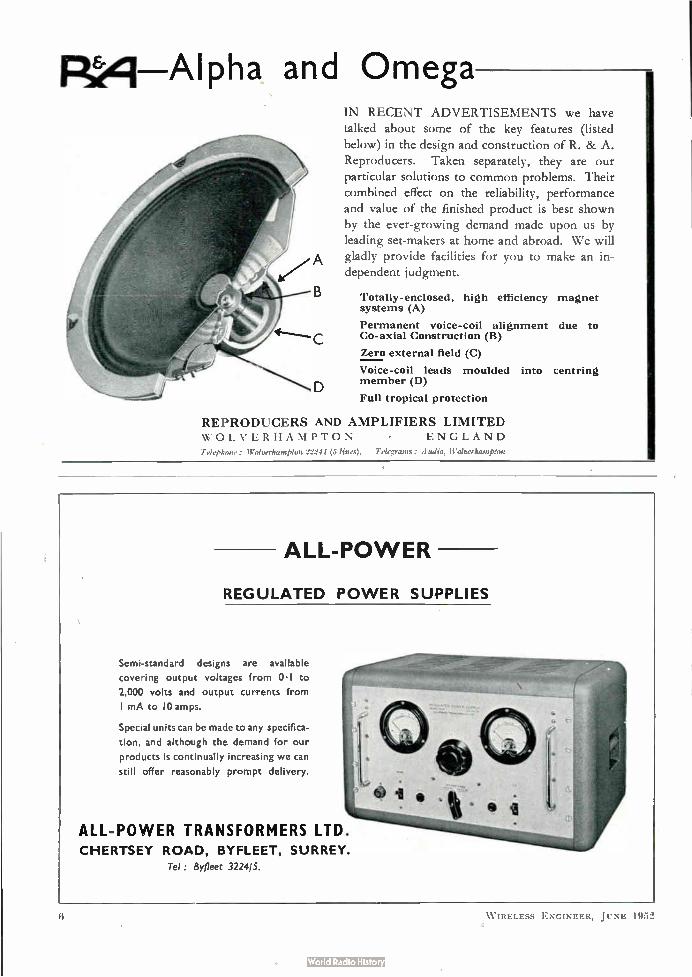
Rerel Alpha and Omega IN RECENT ADVERTISEMENTS we have
talked about some of the key features (listed
below) in the design and construction of R. & A.
Reproducers. Taken separately, they are our
particular solutions to common problems. Their
combined effect on the reliability, performance
and value of the finished product is best shown
by the ever-growing demand made upon us by
leading set-makers at home and abroad. We will
A gladly provide facilities for you to make an in-
dependent judgment.
Totally-enclosed, high efficiency magnet systems (A)
Permanent voice-coil alignment due to Co-axial Construction (B)
Zero external field (C)
Voice-coil leads moulded into centring member (D)
Full tropical protection
REPRODUCERS AND AMPLIFIERS LIMITED WOLVERHAMPTON ENGLAND
Telephone : Wolverhampton 11141 (5 lines). Telegrams: Audio, Wolverhampton
ALL-POWER
REGULATED POWER SUPPLIES
Semi-standard designs are available
covering output voltages from 0.1 to
2,000 volts and output currents from
I mA to 10 amps.
Special units can be made to any specifica-
tion, and although the demand for our
products is continually increasing we can
still offer reasonably prompt delivery.
ALL-POWER TRANSFORMERS LTD. CHERTSEY ROAD, BYFLEET, SURREY.
Tel : Byfleet 3224,5
W IRELESS ENGINEER, JUNE 1952
The "Belling-Lee" page for Engineers
LIST NUMBER
L 758
LIST NUMBER
L 341
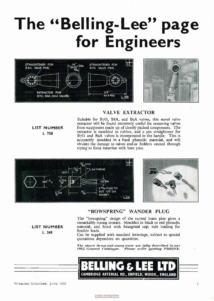
VALVE EXTRACTOR
Suitable for B7G, BSA, and B9A valves, this novel valve extractor will be found extremely useful for removing valves from equipment made up of closely packed components. The extractor is moulded in rubber, and a pin straightener for B7G and B9A valves is incorporated in the handle. This is accurately moulded in a hard phenolic material, and will obviate the damage to valves and/or holders caused through trying to force insertion with bent pins.
.155“DIA
3 % PLUG TO
SUIT •I25' DIA.
SOCKET.
"BOWSP RING" WANDER PLUG
The "bowspring" design of the turned brass pins gives a remarkably strong contact. Moulded in black or red phenolic material, and fitted with hexagonal cap; side loading for flexible leads. Can be supplied with standard letterings, subject to special quotations dependent on quantities.
The abort items and many more are fully described in our 1952 General Catalogue. Please sente quoting P3651WE.
1BELLING &LEE LTD CAMBRIDGE ARTERIAL RD ., ENFIELD, MIDDX., ENGLAND
WIRELESS ENGINEER, JUNE 195'2
600
500
400
300
200
100
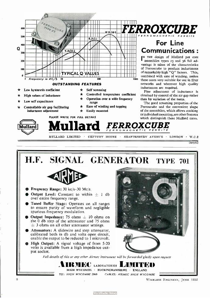
o TYPICAL Q VALUES
•
Y.25/11 3
R 25/ 11
w.2s/ui.s
II
FERRoxcuBE FERROMAGNETIC FERRITE
Frequency In K
OUTSTANDING FEATURES
Low hysteresis coefficient
High values of inductance
Low self capacitance
Controllable air gap facilitating inductance adjustment
000
Self screening
Controlled temperature coefficient
Operation over a wide frequency range
Ease of winding and tapping
Easily mounted
PLEASE WRITE FOR FULL DETAILS
For Line Communications: IN THE design of Mullard pot core
assemblies types 25 and 36 full ad-vantage is taken of the characteristics of Ferroxcube to produce inductances of remarkably high "Q" factors. This, combined with ease of winding, makes these cores very suitable for use in filter networks and wherever high quality inductances are required.
Fine adjustment of inductance is obtained by control of the air gap rather than by variation of the turns. The good screening properties of the
Ferroxcube and the convenient shape of the assemblies, which allows stacking or individual mounting, are other features which distinguish these Mullard cores.
Mullard EETR/Ozme9,E.?ccc...:qPi MULL \RD LIMITED • CENTURY HOUSE • SHAFTESBURY AVENUE • LONDON • W .C.2
(PAF372)
H.F. SIGNAL GENERATOR TYPE 701
• •
Frequency Range: 30 kc/s-30 Mc/s.
Output Level: Constant to within + 1 db over entire frequency range.
• Tuned Buffer Stage: Operates on all ranges to ensure purity of waveform and negligible spurious frequency modulation.
• Output Impedance: 75 ohms + 10 ohms on the 0 db step of the attenuator and 75 ohms 3 ohms on all other attenuator settings.
• Attenuators: A slidewire and step attenuator, calibrated both in db and volts open circuit, enable the output to be reduced to 1 microvolt.
• High Output: A signal voltage of from 5-20 volts is available from a high impedance out-put socket.
Full details of this or any other Airmec instrument will be forwarded gladly upon request
AIRMEIC LABORATORIES LIMITED HIGH WYCOMBE • BUCKINGHAMSHIRE • ENGLAND
TEL: HIGH WYCOMBE 2060 CABLES: AIRMEC HIGH WYCOMBE
W IRELESS ENGINEER, JUNE 1952
Reg. Trade Mark j
fliijflIi t' étausi TYPE GP 3
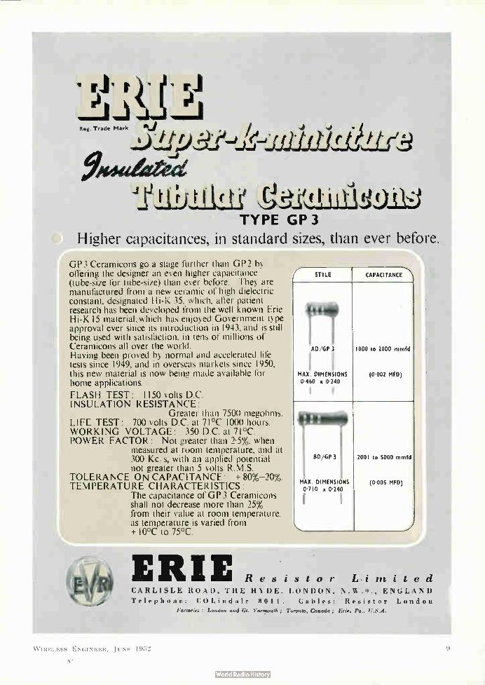
Higher capacitances, in standard sizes, than ever before..
GP3 Ceramicons go a stage further than GP2 by offering the designer an even higher capacitance (tube-size for tube-size) than ever before. They are manufactured from a new ceramic of high dielectric constant, designated Hi-K 35, which, after patient research has been developed from the well known Erie Hi-K 15 material,which has enjoyed Government type approval ever since its introduction in 1943, and is still being used with satisfaction, in tens of millions of Ceramicons all over the world. Having been proved by normal and accelerated life tests since 1949, and in overseas markets since 1950, this new material is now being made available for home applications.
FLASH TEST: 1150 volts D.C. INSULATION RESISTANCE:
Greater than 7500 megohms. LIFE TEST: 700 volts D.C. at 71°C 1000 hours. WORKING VOLTAGE: 350 D.C. at 71°C. POWER FACTOR: Not greater than 2.5%, when
measured at room temperature, and at 300 Kc/s, with an applied potential not greater than 5 volts R.M.S.
TOLERANCE ON CAPACITANCE: + 80%-20%. TEMPERATURE CHARACTERISTICS:
The capacitance of GP 3 Ceramicons shall not decrease more than 25% from their value at room temperature, as temperature is varied from +10°C to 75°C.
STYLE CAPACITANCE.
AD/GP 3
MAX. DIMENSIONS 0-460 o 0.240
1
1000 to 2000 mmfd
(0.002 MFD)
MAX. DIMENSIONS 0.710 o 0.240
I
2001 to 5000 mmfd
(0.005 MFD)
ERIE Resistor Limited CARLISLE ROAD, THE HYDE, LONDON, N. lev. 9., ENGLAND Telephone: COLindale 8011. Cables: Resistor London
Factories : London and Gt. Yarcsouth ; Toronto, Canada ; Erie, Pa.. U.S.A.
W IRELESS ENGINEER, JUNE 1952
A'

Recognised as the Most Reliable Volveholders
HENE PUSH-ON COV POLYT ER
812A— Duodeca 1 FOR CATHODE RAY TUBES
Ref. No. B.I2 U—moulded in Phenol-Formaldehyde with Polythene Cover
B.I2 U.I— „ „ „ without cover
Wholesale Enquiries:—CYRIL FRENCH LTD.. HIGH STREET, HAMPTON WICK. MIDDLESEX • KIN. 2240
Manufacturers' Enquiries:—THE McMURDO INSTRUMENT CO. LTD., VICTORIA WORKS, ASHTEAD, SURREY ASHTEAD 3401
HIGH SPEED
AllTHMATICS
Modern machinery and mass production methods give
you top quality capstan and automatic work and sheet
pressings at a price you are sure to like—and on time.
GRIFFITHS, GILBART, LLOYD AND COMPANY LIMITED
Empire Works, Park Rd.,Birmingham 18 Telephone: NORthern 2132 4
Third Edition
Thermionic
Valve Circuits
By Emrys Williams, Ph.D., B.Eng., M.I.E.E., M.Brit.I.R.E. This well-known book has been comprehen-sively revised for the new edition, and includes a great deal of new material. Illustrated. 21s. net.
"A very good survey of all the main types of valve circuits, presented in such a way that the student may be in a position to understand, or even foresee, further developments."— NATURE.
"Not only helps the student in grasping the theory, but provides the engineer with useful design data."— ELECTRICAL REVIEW.
Pitman INtrieer Suret. kingswesg. Loudon. II .1 .
W IRELESS ENGINEER, JUNE I 9•,2
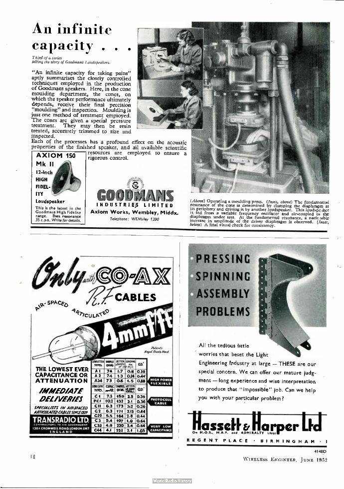
An infinite capacity . Third of a series telling the story of Goodmans Loudspeakers.
• •
"An infinite capacity for taking pains" aptly summarises the closely controlled techniques employed in the production of Goodmans speakers. Here, in the cone moulding department, the cones, on which the speaker performance ultimately depends, receive their final precision "moulding" and inspection. Moulding is just one method of treatment employed. The cones are given a special pressure treatment. They may then be resin .. treated, accurately trimmed to size and inspected. Each of the processes has a profound effect on the acoustic properties of the finished speaker, and all available scientific
resources are employed to ensure a rigorous control. AXIOM 150
Mk II
I2-inch
HIGH
FIDEL-
ITY
Loudspeaker This is the latest in the Goodmans High Fidelity range. Bass resonance 35 c.p.s. Write for details.
INDUSTRIEJS LIMITED
Axiom Works, Wembley, Middx. Telephone: WEMbley 1200
(Above) Operating a moulding press. (Inset, above) The fundamental resonance of the cone is determined by clamping the diaphragm at its periphery and driving it by another loudspeaker. This loudspe.ker is fed from a variable frequency oscillator and air-coupled to the diaphragm under test. At the fundamental resonance, a notic!able increase in amplitude of the driver diaphragm is observed. (Inset, below) A final visual check for consistency.
THE LOWEST EVER CAPACITANCE OR ATTENUATION
IMMEDIATE DELIVERIES
IPAYALLITS IN A/8-5P.4CED ART/CL/LATEO CABLES5/110E/929
TRANSRADIO LTD TO N. 40VERNINIENT
1380 CLIOMWILLROAD.1010014 SW.7 ENGLAND
CABLES
Rd eels
Aegel Aloei
11181111W-
LOWEITIN
rms. IMPED
outs ATTU
etre; LOADING ,,
00.
AI 74 1.7 0.11 0.36 A2 74 1.3 0.24 0.44 A34 73 0.6 1.5 0.88
WIWI« C..1.51C. MED. ATTEN. „
mss. mg» 01114S. fur 08. C 1 7.3 150 2.5 0.36 P.C1 10.2 132 3.1 0.36 C11 6.3 173 3.2 0.36 C2 6.3 171 2.15 0.44 C22 5.5 ,184 2.5 0.44 C3 5.4 197 -1.9 0.64 C33 4.8 220 2.4 0.64 C44 4.1 252 2.1 1.03
HIGH POWER FLEXIBLE
PHOTOCELL CABLE
VERY LOW
CAPACITANCE
¡PRESSING
SPINNING
ASSEMBLY
PROBLEMS
All the tedious little 44
worries that beset the Light
Engineering industry at large - THESE are our
special concern. We can offer our mature judg-
ment - long experience and wise interpretation
to produce that "impossible" job. Can we help
you with your particular problem?
asselh arper LF On P1.0.5., M.A.P. and ADMIRALTY Lists
REGENT PLACE • BIRMINGHAM • I
4-.48L)
W IRELESS ENGINEER, JUNE 1952
OFF ON
,14
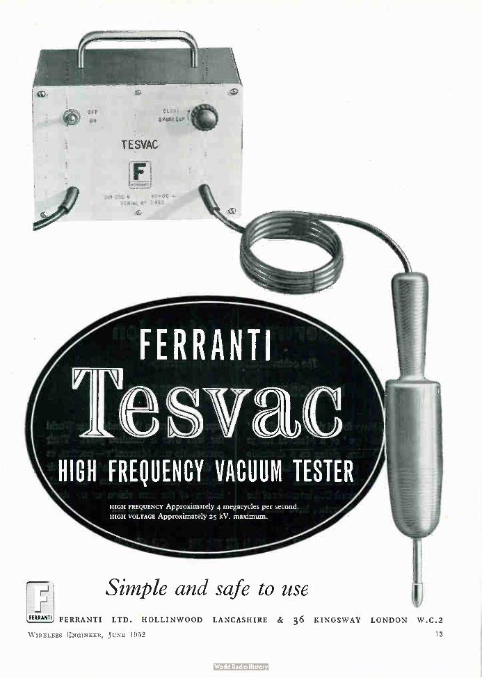
TESVAC
210-250 V 4 0-6 0 — SERiAL T 483
FERRANTI
HIGH FREQUENCY VACUUM TESTER HIGH FREQUENCY Approximately 4 megacycles per second.
HIGH VOLTAGE Approximately 25 kV. maximum.
Simple and safe to use FERRANTI1 FERRANTI LTD . HOLLINWOOD LANCASHIRE & 36 KINGSWAY LONDON W .C.2
W IRELESS ENGINEER, JUNE 1952 IS:
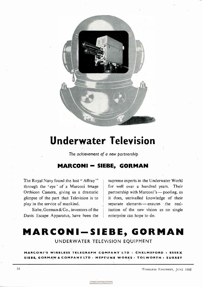
Underwater Television The achievement of a new partnership
MARCONI - SIEBE, GORMAN
The Royal Navy found the lost Affray"
through the eye' of a Marconi Image
Orthicon Camera, giving us a dramatic
glimpse of the part that Television is to
play in the service of mankind.
Siebe, Gorman & Co., inventors of the
Davis Escape Apparatus, have been the
supreme experts in the Underwater World
for well over a hundred years. Their
partnership with Marconi's — pooling, as
it does, unrivalled knowledge of their
separate elements — ensures the real-
isation of the new vision as no single
enterprise can hope to do.
MARCONI--SIEBE, GORMAN UNDERWATER TELEVISION EQUIPMENT
MARCONI'S WIRELESS TELEGRAPH COMPANY LTD • CHELMSFORD • ESSEX SIEBE, GORMAN & COMPANY LTD • NEPTUNE WORKS • TOLWORTH • SURREY
W IRELESS SGINEER, JUNE 1952

WIRELESS ENGINEER
The Journal of Radio Research and Progress
Managing Editor: HUGH S. POCOCK, M.I.E.E.
Editor: W. T. COCKING, M.I.E.E. Technical Editor: Professor G. W. O. HOWE, D.Sc., LL.D., M.I.E.E.
Editorial Advisory Board:
P. A. T. BEVAN, B.Sc., A.M.I.E.E. (British Broadcasting Corporation); F. M. COLEBROOK, B.Sc., A.C.G.I. (National Physical Laboratory); Professor E. B. MOULL1N, Sc.D., M.I.E.E.; A. H. MUMFORD, 0.B.E., B.Sc. (Eng.), M.I.E.E. (G.P.O. Engineering Department); R. L. SMITH-ROSE, D.Sc., Ph.D., M.I.E.E.
(Department of Scientific and Industrial Research)
Volume 29 • Number 345
CONTENTS
JUNE 1 9 5 2
Editorial: The Gyrator .. 143
Anti-Resonant H.F. Transmission Lines by Professor H. M. Barlow, Ph.D. 145
Beat-Frequency Tone Source by C. G. Mayo, M.A., B.Sc. 148
Cathode-Follower Operation by A. J. Shimmins, B.E.E., B.Com. 155
Interference in Television Pictures by G. Diemer, Z. van Gelder and J. J. P. Valeton 164
Correspondence .. 169
New Books 170
Standard-Frequency Transmissions 170
Abstracts and References. Nos. 1487-1796 A.111-A.132
Published on the sixth of each month
Annual Subscription: Home and overseas, 1 year £2 4s. 6d.; 6 months £1 2s. 3d.; Canada and U.S.A. $7.00
Editorial, Advertising and Publishing Offices: Dorset House, Stamford Street, London, S.E.1
Telephone: Waterloo 3333 (60 lines) • Telegrams: Wirenger, Sedist, London
BRANCH OFFICES AT BIRMINGHAM • MANCHESTER AND GLASGOW
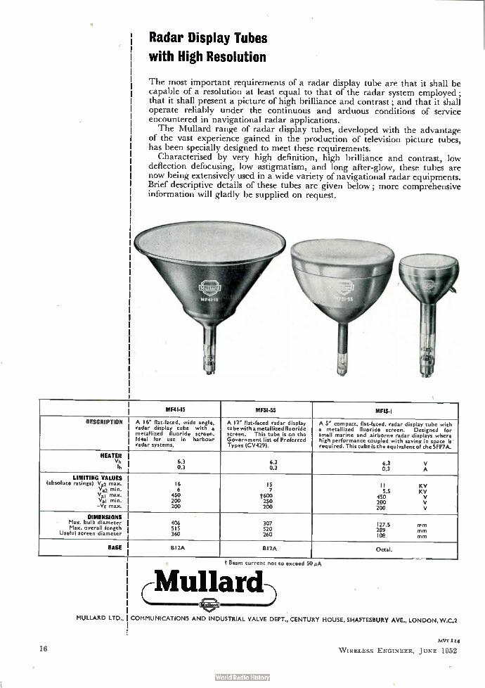
Radar Display Tubes
with High Resolution
The most important requirements of a radar display tube are that it shall be capable of a resolution at least equal to that of the radar system employed; that it shall present a picture of high brilliance and contrast; and that it shall operate reliably under the continuous and arduous conditions of service encountered in navigational radar applications. The Mullard range of radar display tubes, developed with the advantage
of the vast experience gained in the production of television picture tubes, has been specially designed to meet these requirements.
Characterised by very high definition, high brilliance and contrast, low deflection defocusing, low astigmatism, and long after-glow, these tubes are now being extensively used in a wide variety of navigational radar equipments. Brief descriptive details of these tubes are given below; more comprehensive information will gladly be supplied on request.
MF41-I5 MF3I-55 MFIS-I
DESCRIPTION A le flat-faced, wide angle, radar display tube with a metallized fluoride screen. Ideal for use in harbour radar systems.
A 12" flat-faced radar display tubewith a metallizedfluoride screen. This tube is on the Government list of Preferred Types (CV429).
A 5" compact, flat-faced, radar display tube with a metallized fluoride screen. Designed for small marine and airborne radar displays where high performance coupled with saving in space is' required. This tube is the equivalent of the SFP7A.
HEATER Vh Ih
6.3 0.3
6.3 0.3
6.3 V 0.3 A
LIMITING VALUES (absolute ratings) V.2 max.
Va2 min. Val max. Val min. -Vg max. j
16 6
450 200 200
15 7
t600 250 200
II KV S.S KV
450 v 200 v 200 v
DIMENSIONS 1 Max. bulb diameter Max. overall length
Useful screen diameter
406 515 360
307 520 260
127.5 TM
289 mm 1 oe ..
BASE 812A Bl2A Octal.
t Beam current not to exceed 50 //A
Mullard MULLARD LTD., COMMUNICATIONS AND INDUSTRIAL VALVE DEPT., CENTURY HOUSE, SHAFTESBURY AVE., LONDON,W.C.2
16 hIVT 114
W IRELESS ENGINEER, JUNE 1952
WIRELESS ENGINEER
Vol. 29 JUNE 1952 No. 345
The Gyrator
IN the Philips Research Reports for April 1948, B. D. H. Tellegen suggested that network synthesis would be considerably modified, and
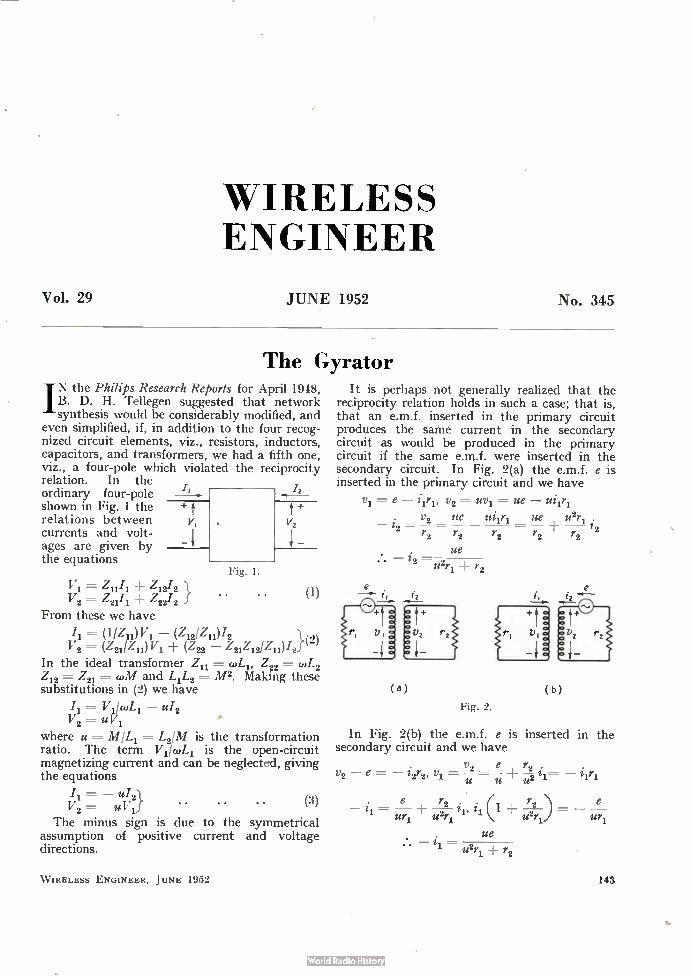
even simplified, if, in addition to the four recog-nized circuit elements, viz., resistors, inductors, capacitors, and transformers, we had a fifth one, viz., a four-pole which violated the reciprocity relation. In the ordinary four-pole shown in Fig. 1 the relations between v, currents and volt-ages are given by the equations
«Vi= Z11i1 ± Z1212 V2 = Z2111 4- Z2212
From these we have
12
Fig. 1.
(1)
/1 = (1/Z11) V1 (Z12/Z11)1.2 V2 == ± (Z22 — ZuZi2/Zii)/2}(2)
In the ideal transformer Z11 = «di, Z22 = cuL2 Z12 = Z21 = 0,M and LiL2 = M 2. Making these substitutions in (2) we have
Vi/wLi — u12
V2 = u where u = M/Li = L2/M is the transformation ratio. The term Vi/coLi is the open-circuit magnetizing current and can be neglected, giving the equations
/1 = f4/2}
V2 = u V1 The minus sign is due to the symmetrical
assumption of positive current and voltage directions.
•
WIRELESS ENGINEER, JUNE 1952
(3)
(a)
It is perhaps not generally realized that the reciprocity relation holds in such a case; that is, that an e.m.f. inserted in the primary circuit produces the same current in the secondary circuit as would be produced in the primary circuit if the same e.m.f. were inserted in the secondary circuit. In Fig. 2(a) the e.m.f. e is inserted in the primary circuit and we have
= e — 111'1, v2 =--- uvl = ue —
v2 ue ue u2r == _L ; r2 r2 r2 r2 r2
ue • • — i2 u2r, r2
t,
Fig. 2.
(b)
In Fig. 2(b) the e.m.f. e is inserted in the secondary circuit and we have
v2 e , r2 . v2 — e = — i2r2, vj. — — —2- 21= —
u u u
1 ur u2r 1' 1
ue • — ¡J.= WTI r2
e
143
mr.
Hence, a positively directed e.m.f. in either case produces a negative current, or expressed in another way, a right-handed e.m.f. in either circuit produces a right-handed current of the same magnitude in the other circuit. Up to this point we have confined our attention
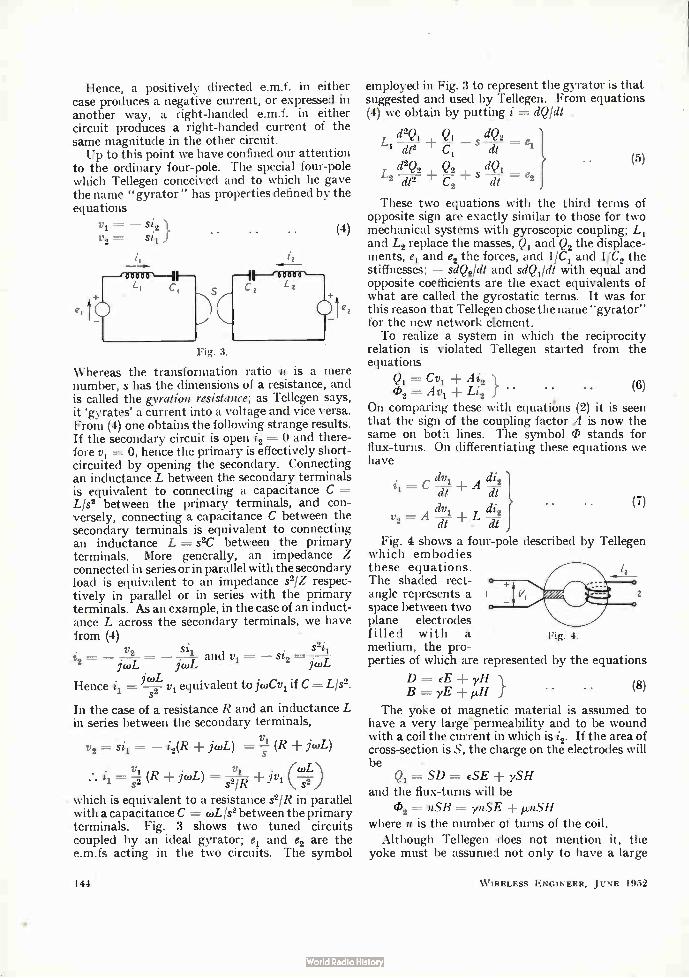
to the ordinary four-pole. The special four-pole which Tellegen conceived and to which he gave the name " gyrator " has properties defined by the equations
Vi = — Si2 V2 = Si l
(4)
Fig. 3.
Whereas the transformation ratio u is a mere number, s has the dimensions of a resistance, and is called the gyration resistance; as Tellegen says, it 'gyrates' a current into a voltage and vice versa. From (4) one obtains the following strange results. If the secondary circuit is open 2 = o and there-fore yl = 0, hence the primary is effectively short-circuited by opening the secondary. Connecting an inductance L between the secondary terminals is equivalent to connecting a capacitance C L/s2 between the primary terminals, and con-versely, connecting a capacitance C between the secondary terminals is equivalent to connecting an inductance L = s2C between the primary terminals. More generally, an impedance Z connected in series or in parallel with the secondary load is equivalent to an impedance s2/Z respec-tively in parallel or in series with the primary terminals. As an example, in the case of an induct-ance L across the secondary terminals, we have from (4)
V2 Stii S2ii icur, and 1,1 = — Si2 = -
jcuL
Hence i1 = jcoL— y1 equivalent to jwCv„ if C = L/S2. s2
In the case of a resistance R and an inductance L in series between the secondary terminals,
v2 =s11= — i2(R jcoL) = ILls (R jwL)
sl = 11. (R jcuL) ,:vi (cusL2)
s21R m
• which is equivalent to a resistance s2/R in parallel with a capacitance C = coL/s2 between the primary terminals. Fig. 3 shows two tuned circuits coupled by an ideal gyrator; el and e2 are the e.m.fs acting in the two circuits. The symbol
144
dv di v A L 2 2 dt • dt
employed in Fig. 3 to represent the gyrator is that suggested and used by Tellegen. From equations (4) we obtain by putting i = dQldt .
L d2Q1 ± Q1 s dQ2 = e 1 dt2 Cl dt 1
d2Q2 Q2 dQ 1 1 S — = e dt2 dt 2 2
These two equations with the third terms of opposite sign are exactly similar to those for two mechanical systems with gyroscopic coupling; L1 and L2 replace the masses, Q1 and Q2 the displace-ments, e, and e2 the forces, and 1/C1 and 1/C2 the stiffnesses; — sdQ2Idt and sd4211dt with equal and opposite coefficients are the exact equivalents of what are called the gyrostatic terms. It was for this reason that Tellegen chose the name "gyrator" for the new network element. To realize a system in which the reciprocity
relation is violated Tellegen started from the equations
Q1 = Cvl Ai2 Li2 J "
• • (5)
(8)
On comparing these with equatiks (2) it is seen that the sign of the coupling factor A is now the same on both lines. The symbol 0 stands for flux-turns. On differentiating these equations we have
± A i1 dt di2 1 dt
dv
(7)
Fig. 4 shows a four-pole described by Tellegen which embodies these equations. The shaded rect-angle represents a space between two plane electrodes filled with a medium, the pro-perties of which are represented by the equations
D eE yH B = yE j
The yoke of magnetic material is assumed to have a very large permeability and to be wound with a coil the current in which is i2. If the area of cross-section is S, the charge on the electrodes will be
SD = ¿SE ySH and the flux-turns will be
02 = nSB = ynSE linSH where n is the number of turns of the coil.
Although Tellegen does not mention it, the yoke must be assumed not only to have a large
Fig. 4.
2
(8)
W IRELESS ENGINEER, JUNE 1952
permeability, but also to be a dielectric of very small dielectric constant, otherwise it would form a short-circuit or a very large capacitance across the terminals 1.
If / is the distance between the electrodes, then = lE and i2 = Win; hence
i2 Es yns 1
ynS tees = e / 1 / 2
(9)
By putting D = e0E P and B = 1.1.011 e — e0= K and it — x we obtain for the electric polarization P and magnetic polarization J
P = KE yH}
J =-- yE xH So what is required to carry out this scheme is a magnetic dielectric which is polarized both electrically and magnetically by either an electric or a magnetic field. The coefficient y is a measure
.. (10)
of the cross susceptibility; its dimension is the reciprocal of a velocity. If the molecules of a dielectric were both electric and magnetic dipoles, then, on applying either an electric or magnetic field, they would be oriented and P and J would both be increased. The device shown in Fig. 4 would then function as a gyrator. Tellegen calls y2lEti, the coupling coefficient and states that for the best results it should be as near unity as possible; in other words, y should be the geometric mean of e and µ, or perhaps more correctly of K and x. If P and J were due entirely to combined electric and magnetic dipoles, the ratio PI J. would be independent of E and H and therefore from (10) n/y =y/x and y2 = nx. Up to this point we have discussed the gyrator
as it existed in the mind of B. D. H. Tellegen in 1948. We propose to postpone to our next number the consideration of its subsequent development and practical realization.
ANTI-RESONANT H.F. TRANSMISSION LINES
Input Impedance Characteristics
By Professor H. M. Barlow, Ph.D., M.I.E.E.
SO many aspects of this subject have already been covered with such admirable thorough-ness that it is surprising to find an exception
justifying further discussion. The evaluation in a convenient form of maximum input resistance and reactance values for anti-resonant lines has apparently not been given all the attention it deserves and the purpose of this paper is to deal with that problem in the particular case of the short-circuited quarter-wavelength line.
Line Characteristics
A short-circuited line of length / with uniformly-distributed constants, characteristic impedance Z0 and propagation coefficient P = a ± jfi has an impedance z, at input given by:—
Zs = Z0 tanh Pl .... .. .. (1) For high frequencies we can assume with suffi-
cient accuracy that Z0 is purely real and (1) can therefore be re-written in terms of resistive and reactive components of Zs as follows:—
Z0 sinh a./ . cosh cf./ Zs = Rs ± jX, — . Gmh2 cd + cos2 fil)
,; ( Z0 sin Pl. cos 13l ± i sinh2 al ± cos2 IN) • • (2)
MS accepted by the Editor, September 1951
W IRELESS ENGINEER, JUNE 1952
G. W. O. H.
Now for comparatively short lines whose length is comparable with the wavelength a/ < 1, so that sinh al a/, and with slightly less accuracy cosh a/ e.e. 1. Thus we have:—
al R3/Z0 — • • (3)
cc2/2 cos2 /31
sin /31. cos fil and X3/Z0 —
a2/2 cos2 pl These normalized resistive and reactive com-
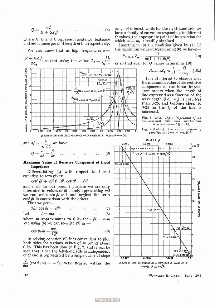
ponents of the impedance at input when plotted in terms of line length as a fraction of wavelength give curves, Fig. 1, which are well known and can be delineated over the greater part of the range neglecting the a2/2 term compared with cos2 fil in the denominator of (3) and (4). When, however, / approaches A/4 both terms in the denominator become significant.
It is convenient to plot the results for a line of given Q defined as
27,[Maximum energy stored in the magnetic field] Energy dissipated per cycle
Neglecting any loss in the short-circuit at the end of the line we find:*
.. (4)
• See for example 'High Frequency Trancruksion Lines,' by Willis Jackson, Methuen Monograph, p. 100.
145
Q = R GZ02 • • • • (5)
where R, G and L represent resistance, leakance and inductance per unit length of line respectively.
We also know that at high frequencies a =
(R GZ02) so that, using the values Zo
2Z0
range of interest, while for the right-hand side we have a family of curves corresponding to different Q values, the appropriate point of intersection for which m = nt, is readily obtained.
Inserting in (3) the condition given by (7) for the maximum value of Rs and using (6) we have:-
1 Rs,max1Z = . . (10)
° al(1 ± 1/16Q2) • • or so that even for Q values as small as (10)
smx 12-77 AT MI= 02498 Z .
CURVE OF
I I Zs /Zo
i 0
Xs max ' INVERTED CURVE OF
- 6-07 Zo
AT ini0.26.-2 Xs/Zo
8 ...---" y
- 649 AT Q
M I=0-238
e 6 .
s • o ...
4
i xsizo I 2
R/Z0 44
075 01 0-125 015 0.175 01 0-225 0-25 0.275 0-D 0-025 0-05 0
LENGTH OF LINE EXPRESSED AS A FRACTION OF WAVELENGTH. VALUES OF in =
1 and Af = .v.w we have
ir fi Q =
Maximum Value of Resistive Component of Input Impedance
Differentiating (3) with respect to / and equating to zero gives:—
cos2 2fl/ sin 13l. cos fil = a212
and since for our present purpose we are only interested in values of fil closely approaching ir/2 we can write sin fil = 1 and neglect the term cos° fil in comparison with the others. Thus we get:-
2/31. cos fil = 662/2 (7)
Let (8) where m approximates to 0-25 then fil = 2rm and using (6) we can re-write (7) as:—
cos 2rm = —4Q2 . • (9)
In solving equation (9) it is convenient to plot both sides for various values of m round about 0.25. This has been done in Fig. 2, and it will be seen that, since the left-hand side is independent of Q and js represented by a single curve of slope
d (cos 2rm) = — 2r very nearly, within the dm
146
0.0003
Rs,max1Z0 ese = Q fb Ott wrni
It is of interest to observe that the maximum value of the resistive component of the input imped-ance occurs when the length of line expressed as a fraction of the wavelength (i.e., mi) is just less than 0.25, and becomes closer to 0.25 as the Q of the line is increased.
Fig. 1 (left). Input impedance of an anti-resonant line with short-circuit
termination and Q = 10.
Fig. 2 (below). Curves for solution of equation cos 2irm = irm/4421.-
VALUES OFp
0.0002 0.0001
\ FOR Q..10 CURVE OF irmi4e
m 1.0.24979
COS 2117n
18
16
14
12
10
e
6 FOR2-20
4 Mi .. .24992
FOR Q= 50
117I 0-24999 0 0.2497 01498 0-2499 0-25
LENGTH OF LINE EXPRESSED AS A FRACTION OF WAVELENGTH
VALUES OF = lA
VALUES OF COS 2/T
in & ffm/4Q2
W IRELESS ENGINEER, JUNE 1952
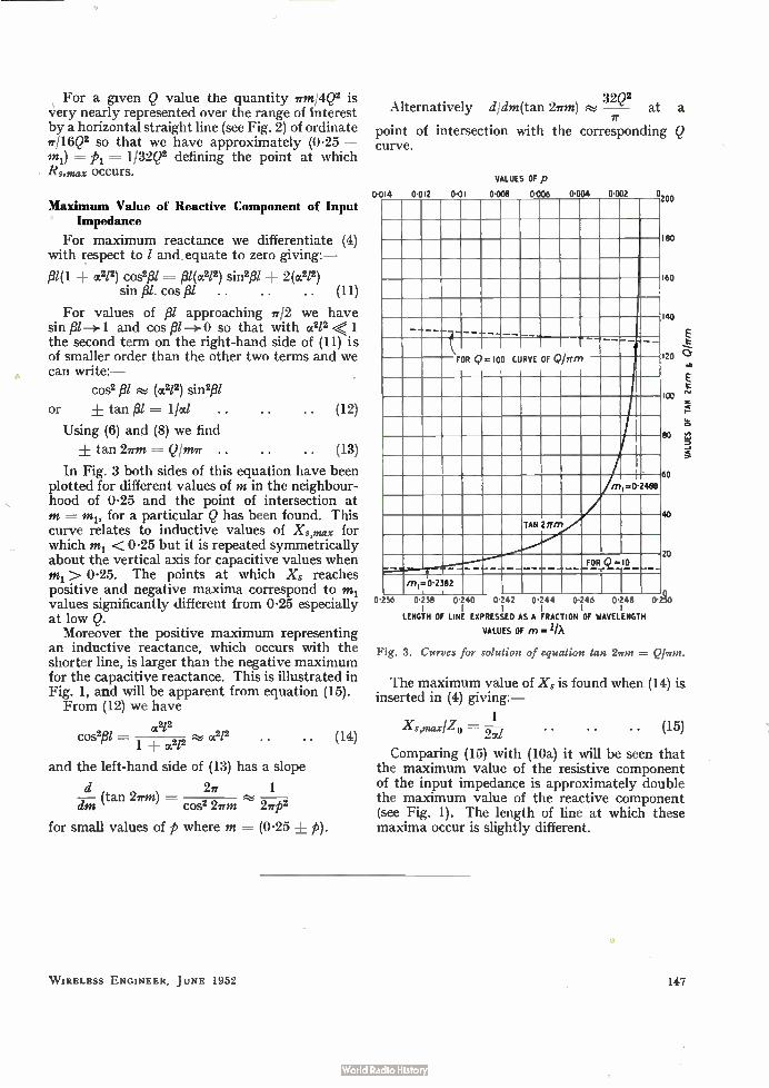
\ For a given Q value the quantity 7rm/.4Q2 is very nearly represented over the range of Interest by a horizontal straight line (see Fig. 2) of ordinate ir/16Q2 so that we have approximately (0.25 — m1) =A = 1/32Q2 defining the point at which Rs,max occurs.
Maximum Value of Reactive Component of Input Impedance
For maximum reactance we differentiate (4) with respect to / and, equate to zero giving:—
f31(1 ot212) cos2f31 = fil(a212) sin2/3/ 2(a2/2) sin fil. cos fil . . . . . . (11)
For values of f31 approaching 7712 we have sin /3/ —›- 1 and cos I31—>-0 so that with a2/2 < 1 the second term on the right-hand side of (11) is of smaller order than the other two terms and we can write:—
cos2 8/ (a212) sin2f3/
or ± tan = lied .. (12)
Using (6) and (8) we find
± tan 27rm = Q/mir (13)
In Fig. 3 both sides of this equation have been plotted for different values of m in the neighbour-hood of 0.25 and the point of intersection at m for a particular Q has been found. This curve relates to inductive values of Xs,max for which m1 < 0.25 but it is repeated symmetrically about the vertical axis for capacitive values when m1> 0-25. The points at which Xs reaches positive and negative maxima correspond to m1 values significantly different from 0.25 especially at low Q.
Moreover the positive maximum representing an inductive reactance, which occurs with the shorter line, is larger than the negative maximum for the capacitive reactance. This is illustrated in Fig. 1, and will be apparent from equation (15). From (12) we have
,212 cos2f3/ 1 ± 212 ,212 . . (14)
cc and the left-hand side of (13) has a slope
d 27r 1 d—tn (tan 2i-m) =
cos2 2em 2irp2
for small values of p where m = (0.25 ± p).
32Q2 Alternatively c//c/m(tan 277-m) eke, — at a
IT
point of intersection with the corresponding Q curve.
O.
O
• •
VALUES OF p • •
201
181
161
141
_____ 1 Q
fi = 100 CURVE OF ObTm 121 FOR
101
leo
I L DO
M 1.0•2488
40 TAN 2rrrn
20 FOR _ Q =10 —
m 1=02082 I
0•2%0 236 0.238 0.240 1
0142 0.244 0-246 0.248 I
LENGTH OF LINE EXPRESSED AS A FRACTION OF WAVELENGTH
VALUES OF m. lIA
VALUES OF TAN 2em & Plem
Fig. 3. Curves for solution of equation tan 2um = Qlvm.
The maximum value of Xs is found when (14) is inserted in (4) giving:-
1 Xmn,sx/Zo — 27-d . . (15)
Comparing (15) with (10a) it will be seen that the maximum value of the resistive component of the input impedance is approximately double the maximum value of the reactive component (see Fig. 1). The length of line at which these maxima occur is slightly different.
W IRELESS ENGINEER, JUNE 1952 147
BEAT-FREQUENCY TONE SOURCE Mathematical Theory of Mixing
By C. G. Mayo, M.A., B.Sc.. M.I.E.E. (Research Department, B.B.C. Engineering Division)
SUMMARY.—In a beat-frequency tone source it is required to obtain an output signal whose frequency is the difference of the frequencies of two signals, one of which is usually fixed and the other variable. Three methods are discussed:—Method 1: Multiplication in a square-law device. Method 2: Addition and linear rectification of the sum, it being understood that one signal has much greater amplitude than the other. Method 3: Addition of one component to a square wave synchronous with the other, and linear rectification of the sum.
1. Notation and Methods of Calculation
T0 facilitate calculation use will be made of Taylor's Theorem or the equivalent principle of the superposition of small variations. The
distortion in which we are interested will, in a practical case, be of the order of 0-25% or 0.0025. If this is a first-order quantity, second-order quantities will be of the order 0.00000625 and will be neglected. Now by Taylor's Theorem if an output q is a function of several variables x1 x2. . x, the total change 8q due to changes 8x1 8x2. . 8x, in x1 x2.. x, is to the first order
k 8x2 ± .... -1- —...k 8x,
xl bx2 ox,
2. Method 1: Multiplication in a Square-Law Device
Let the fixed oscillator signal be E1 sin st and the variable E2 sin (s 0)t and let the law of the device be E = A -I- Bx Cx2 where A, B and C are constant, and x is the applied signal. In the present case x = E1 sin st + E2 sin (s -F w)t. We then have
E --- A -F B[Ei sin st -F E2 sin (s (.0)t]
CEE, sin st + E2 sin (s w)t]2
Now the only term in wt is obtained from
E3 = 2C El sin st.E2 sin (s (.0)t = C El E2[ cos wt — cos (2s w)t]
i.e., the beat-frequency output is proportional to the amplitude of both the fixed and variable oscillator voltages. If now the device has a law containing higher powers than the square, as will be usual in practice, output signals of frequency /wen will appear, where n is an integer depending on the power referred to. Hence the freedom from harmonics will depend upon how exactly the multiplying device obeys a square law.
3. Method 2: Addition and Rectification This case is treated by W. R. Bennett—"New
Results in the Calculation of Modulation
148
Products," Bell System Technical Journal, Vol. 12' 1933, pp. 228-243. His analysis is by means of a double Fourier series and the results are given in terms of elliptic integrals. His equation (9)
Ama ="-- A ±mts = 2Pf" arc cos( — K cos y)
cos ny dy f (cos x -F K cos y) cos mx dx (1) 'IT 0 o
gives the amplitude of the typical components of angular frequency mp ± nq, for inputs P cos x and PK cos y, where x = pt and y = qt. Imagine a three-dimensional diagram of z P cos x PK cosy
against x and y. This diagram repeats along both x and y axes with a period 27r. All relevant in-formation is contained in a rectangular section of the diagram between — e and w on both x and y axes. If in this diagram all negative values of z are replaced by zero the effect is then like a rect-angular plane with a roundéd hill rising from it. The contour corresponding to the foot of the hill is given by the equation
z = P cos x -I- PK cos y = O. . (2) Now Z = [P ccis x + PK cos y], where the square brackets indicate that all negative values are replaced by zero, corresponding to the effect of an ideal rectifier, can be represented by a Fourier series. The series is double, since there are two independent variables, and by symmetry con-tains only cosine terms. The series is
Z = Z Ama cos mx cos ny = A00 + A10 cos x A01 cosy -I- An cos x cosy
and the coefficients are to be determined in a manner very similar to that used in a single Fourier series by the integral
cos mx dx f cos ny dy 1 f
-« In practice the fact that Z is zero for values of x and y which make P cos x -1- PK cosy negative
MS accepted by the Editor, May 1951
W IRELESS ENGINEER, JUNE 1952
is registered by proper choice of limits in the integrals as iS usual also in single Fourier series.
Since Bm, cos mx cos ny
• Bton {cos (mx _ ny) ± cos (mx + ny)) the coefficient of the term containing
cos (mx ± ny) is B./2.
Now replace x by pt and y by qt so that the terms to be added and linearly rectified are
P cos pt + PK cos qt (i.e., of angular frequencies p and q) then the components of angular frequency mp nq are given by B./2 or by A. in the cited formula. The above is not intended to be other than an
outline of the paper cited which should be con-sulted for a full and rigorous discussion. This solution is valid for all values of K, and in general involves elliptic integrals. The terms in which we are here interested are
Au, A22 and A33 giving the amplitude of the beat-frequency component and its second and third harmonics. A22 and A33 are not computed in the cited paper. When K is not small the harmonics are large and the practical case in which we are interested is when one of the signals is small compared with the other and K is of the order 0.01. In that case it is unnecessary to use elliptic integrals, and for uniformity A11, A22 and A33 will be calculated approximately here.
From (1)
2P = — f n-e cos my dy f (cos x + cos 0) cos mxdx 1r2 o o
where cos 0 = K cos y
= 2P J .' fo'-° {cos (m2+ 1)x cos my dy
77.2 0 + cos (m — 1)x
2 + cos 0 cos mx} dx
e d [sin (m ± 1)x + sin (m ± 1)x = J772 o cos my y m + 1 m — 1
± 2 cos 0 sin mx1 m J o
P so cos my dy {sin ± 1)0 ir m + 1
sin (m — 1)0 2 cos 0 sin m01 m — 1 m
An = +
If in equation (3) m = 1 then
—2P2 r (sin y)(K sin y) N/1 — K2cos2y dy IT 0
PK — to first order of K ir
Similarly,
A 2Pr sin 2y 22 — 2- —7T 4
{2 — K2cos2y(K2cos y) (sin y)} dy
PK2 = — -- to second order of K
417-
sin 3y 9 {(sin 30)(K sin y)} dy
PK3 to third order of K 8ir
and 2P
A33 0 f
Thus the fundamental beat-frequency output has amplitude PK/e, the second-harmonic amplitude is PK2147r and the ratio of second-harmonic amplitude to fundamental amplitude is K/4. The third harmonic is of the third order in K. The amplitude of the beat-frequency term is proportional to the amplitude of the smaller input component.
4. Method 3: Addition of a Square Wave and a Sine Wave
4.1. General In this method a square wave synchronous with
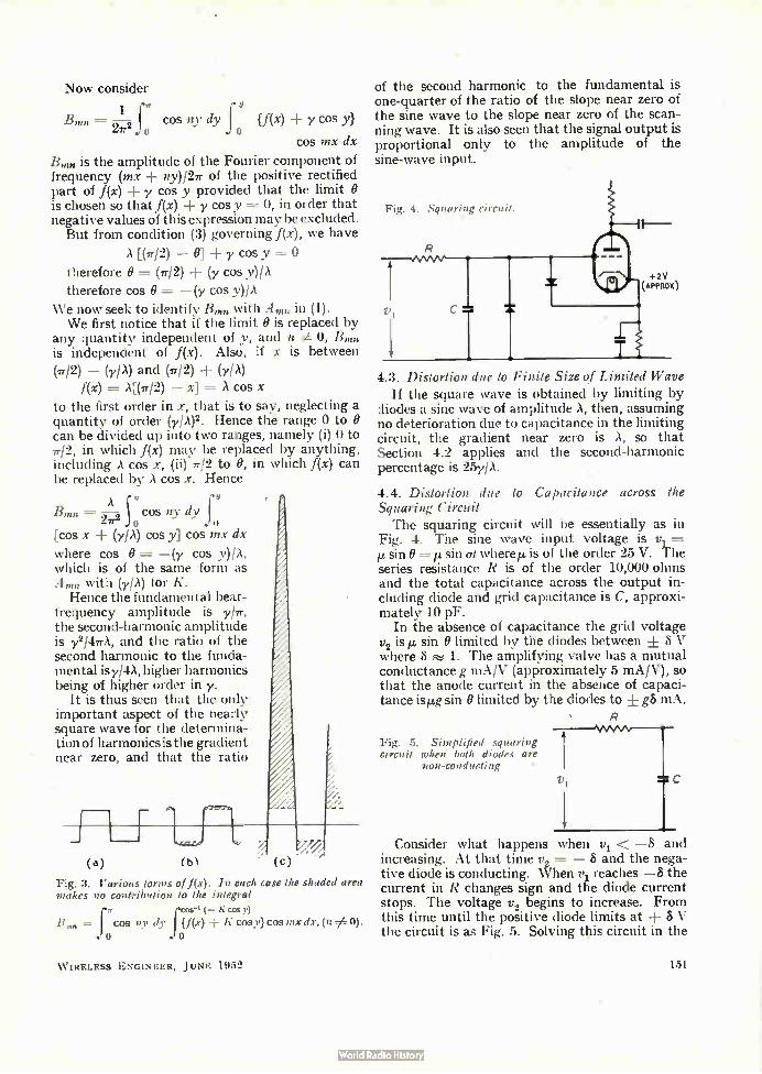
the variable frequency is added to the fixed-frequency sine-wave output and the sum is linearly rectified. The sine-wave peak value is less than that of the square wave and thus the sum is positive only when the square wave is positive. Thus the positively rectified signal consists of the positive square wave plus the seg-ments of the sine wave which coincide in time with the positive square wave. Thus the square wave acts as a switch; when it is positive the sine wave appears in the output but not when it is negative. This is shown in Fig. 1. The opera-tion of a switch is equivalent to multiplication by unity when the switch is closed and by zero when the switch is open and so the rectified result is equal to the square-wave positive half cycles plus the product of a 1, 0, 1, 0, square wave by a sine wave. Now the Fourier series of a square wave
Integrating by parts we get
( — 1)m -4-1 1-9-2 in sin mY {cos (m + 1)0 + cos (m — 1)0 — 2 cos 0 cos m0 o m
2P in {sin my , (— 1)tn+ 2 (sin m0) (K sin y)} dy
o in
WIRELESS ENGINEER, JUNE 1952
2 sin 0 sin mt? dO d
m Jdy Y
(3)
149
consists of fundamental and odd harmonics only. If such a square wave containing angular fre-quencies s, 3s, 5s, etc., is multiplied by a sine wave of angular frequency (s — cu) the resultant frequencies are
s — s, s — w ± 3s, s — w + 5s, etc.
Of these only one namely co is an audio frequency —the rest are supersonic and in particular 2w, 3co, etc., are absent. Thus the output is free from harmonics of the fundamental beat frequency. The effect is very similar to the scanning of a
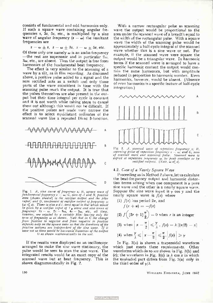
wave by a slit, as in film recording. As discussed above, a positive pulse added to a signal and the sum rectified acts as a switch and only those parts of the wave coincident in time with the scanning pulse reach the output. It is true that the pulses themselves are also present in the out-put but their time integral per cycle is constant and it is not worth while taking steps to cancel them out although this would not be difficult. If the positive pulses are made very narrow the effect is to select equidistant ordinates of the scanned wave like a repeated Dirac 8-function.
A
D
Fig. 1. A, sine curve of frequency s; B, square wave of fundamental frequency s — to; C, sum of A and B, positive area (shown shaded) is the rectifier output and the filter input; and D, component of rectifier output of frequency co (co < s). There is also a d.c. term equal to that which would be given by a rectifier input of V B alone and also terms of frequency 2s — w, 2s — 3co, 4s — 3co, etc., all these, however, are rejected by a suitable filter leaving only the term of frequency co as shown. Note that in C the change from positive to negative and from negative to positive depends only on the square wave so that the durations of the positive sections are independent of the sine wave. If it were not so there would be harmonic 'distortion of the output
D as shown mathematically in the text.
If the results were displayed on an oscilloscope arranged to make the sine wave stationary, the pulse would be seen to scan the sine wave. The integrated results would be an exact copy of the scanned wave but at beat frequency. This is shown diagrammatically in Fig. 2.
150
With a narrow rectangular pulse as scanning wave the output would be proportional to the area under the scanned wave of a breadth equal to the width of the rectangular pulse. With a square wave the width of the scanning pulse would be approximately a half-cycle integral of the scanned wave whether this is a sine wave or not. For example, if the scanned wave were square the output would be a triangular wave. In harmonic terms if the scanned wave is arranged to have a specific harmonic content the output would con-tain the same harmonics, but with amplitude reduced in proportion to harmonic number. Even harmonics, however, would be absent. (Absence of even harmonics is a specific feature of half-cycle integration.)
«."\/\.,"\./ \/.•./"./."../.\/\7\«."\.;\
Fig. 2. A, scanned wave of repetition frequency s; B. scanning pulse of repetition frequency s — w; and C, sum of scanned wave and scanning pulse. Scanned wave is copied at repetition frequency w, by peak envelope or by
rectified outputs. (Note, w < s).
4.2. Case of a Nearly Square Wave Proceeding as in Method 2 above, let us calculate
the beat-frequency output and harmonic distor-tion terms arising when one component is a pure sine wave and the other is a nearly square wave. Suppose the sine wave input is y cos y and the nearly square wave is f(x) where
(1) f(x) has period 2e, and
f (x 7r) = —f(x)
(2) f ([2r + = 0 when r is an integer
< , f(x) = [(1712) — x]
f(x) > y
(3) when
(4) when
7T X - -
2
7T
X - -2
In Fig. 3(a) is shown a trapezoidal waveform which just meets these requirements. Other waveforms which do so are shown in Fig. 3(b) and (c); the waveform in Fig. 3(c) is A cos x in which the unshaded part differs from Fig. 3(a) only in the third order of y/A.
W IRELESS ENGINEER, JUNE 1952
Now consider
1 e 13mn = —2,2fo cos ny dy {f(x) + y cos y}
o cos mx dx
13,ms is the amplitude of the Fourier component of frequency (mx ny)/27r of the positive rectified part of f(x) ± y cos y provided that the limit is chosen so that f(x) ± y cosy = 0, in order that negative values of this expression may be excluded. But from condition (3) governing f(x), we have
A [(7r/2) — 0] + y cosy
therefore O = (e/2) -I- (y cos y)/A
therefore cos O = —(y cos y)/A
We now seek to identify Bmn with Am,1 in (1). We first notice that if the limit O is replaced by
any quantity independent of y, and n é 0, Btnn
is independent of f(x). Also, if x is between (7r/2) — (y/A) and (e/2) (y/A)
f(x) = A[(7712) — = A cos x
to the first order in x, that is to say, neglecting a quantity of order (y/A)2. Hence the range 0 to O can be divided up into two ranges, namely (i) 0 to 7r/2, in which f(x) may be replaced by anything, including A cos x, (ii) 7r/2 to 0, in which f(x) can be replaced by A cos x. Hence
0
— cos ny dy 21r2 o fo
[cos x (y/A) cos y] cos mx dx
where cos O —(y cos y)/A, which is of the same form as A. with (y/A) for K.
Hence the fundamental beat-frequency amplitude is yie, the second-harmonic amplitude is y2/47rA, and the ratio of the second harmonic to the funda-mental is y/4A, higher harmonics being of higher order in y.
It is thus seen that the only important aspect of the nearly square wave for the determina-tion of harmonics is the gradient near zero, and that the ratio
(c)
Fig. 3. Various forms of f(x). In each case the shaded area makes no contribution to the integral
ff Carl ( - K cos y) B „,„ = f cos ny dy f (fix) K cosy) cos mx dx, (n 0).
o
W IRELESS ENGINEER, JUNE 1952
of the second harmonic to the fundamental is one-quarter of the ratio of the slope near zero of the sine wave to the slope near zero of the scan-ning wave. It is also seen that the signal output is proportional only to the amplitude of the sine-wave input.
Fig. 4.. Squaring circuit.
4.3. Distortion due to Finite Size of Limited Wave If the square wave is obtained by limiting by
diodes a sine wave of amplitude A, then, assuming no deterioration due to capacitance in the limiting circuit, the gradient near zero is A, so that Section 4.2 applies and the second-harmonic percentage is 25y/A.
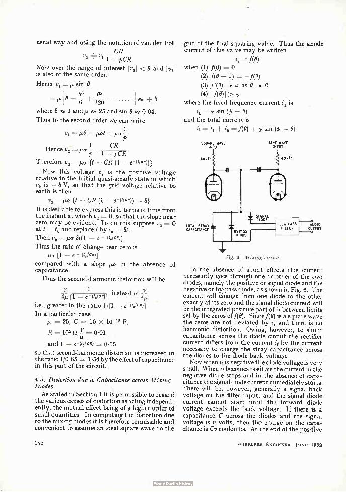
4.4. Distortion due to Capacitance across the Squaring Circuit The squaring circuit will be essentially as in
Fig. 4. The sine wave input voltage is y1 — 1.t. sinO = it sin at where ji is of the order 25 V. The series resistance R is of the order 10,000 ohms and the total capacitance across the output in-cluding diode and grid capacitance is C, approxi-mately 10 pF.
In the absence of capacitance the grid voltage y2 is p. sin O limited by the diodes between + 8 V where 8 1. The amplifying valve has a mutual conductance g mA/V (approximately 5 mA/V), so that the anode current in the absence of capaci-tance isle sin O limited by the diodes to ± g8 mA.
Fig. 5. Simplified squaring circuit when both diodes are
non-conducting
Consider what happens when y1 < —S and increasing. At that time y2 = — 8 and the nega-tive dioçle is conducting. When y1 reaches —8 the current in R changes sign and the diode current stops. The voltage y2 begins to increase. From this time until the positive diode limits at ± 6 V the circuit is as Fig. 5. Solving this circuit in the
151
usual way and using the notation of van der Pol,
CR • v = v
2 • 11 + pcR Now over the range of interest I v21 < is also of the same order.
Hence y1 =IL sin O
in e e
8 and It'll
where 8 :%s 1 and th 25 and sin O 0-04.
Thus to the second order we can write
v1= 0
1 CR Hence y2 µa .
p 1 -I- pcR Therefore y2 = ¡La {t — CR (1 —
Now this voltage y2 is the positive voltage relative to the initial quasi-steady state in which y2 is — 8 V, so that the grid voltage relative to earth is then
y2 = it.cr {t — CR (1 — e-(110R)) — 8)
It is desirable to express this in terms of time from the instant at which y2 =-- 0, so that the slope near zero may be evident. To do this suppose y2 = at t = to and replace t by to -I- St.
Then y2 = ,ua 841. — e - (1.1cR))
Thus the rate of change near zero is
µa [1 — e - (toleR)]
compared with a slope µa in the absence of capacitance.
Thus the second-harmonic distortion will be
1 4yit [1 — e---(toloa.)] instead of —y
i.e., greater in the ratio 1/[1 — elto/cR)]
In a particular case = 25, C = 10 x 10-12 F,
R =104 n, 0-01
and 1 — e- (to/cR) = 0-65
so that second-harmonic distortion is increased in the ratio 1/0.65 = 1 -54 by the effect of capacitance in this part of the circuit.
4.5. Distortion due to Capacitance across Mixing Diodes
As stated in Section 1 it is permissible to regard the various causes of distortion as acting independ-ently, the mutual effect being of a higher order of small quantities. In computing the distortion due to the mixing diodes it is therefore permissible and convenient to assume an ideal square wave on the
152
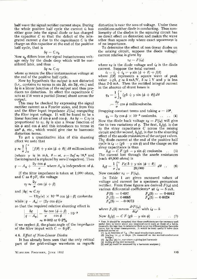
grid of the final squaring valve. Thus the anode current of this valve may be written
i2 =-- f(0)
when (1) f(0)
(2) 1(8 + = —AO)
(3) f'(0) —›- oo as 0 0
(4) 1.1(0)1> where the fixed-frequency current i1 is
= y sin (4. 0)
and the total current is
= i2 = f(0) Y sin (4) +
SQUARE WAVE INPUT
TOTAL 5TRAv CAPACITANCE
SINE WAVE INPUT
Fig. 6. Mixing circuit.
SIGNAL DIODE
AUDIO OUTPUT
In the absence of shunt effects this current necessarily goes through one or other of the two diodes, namely the positive or signal diode and the negative or by-pass diode, as shown in Fig. 6. The current will change from one diode to the other exactly at its zero and the signal diode current will be the integrated positive part of it between limits set by the zeros of f(8). Since f(0) is a square wave the zeros are not deviated by j1 and there is no harmonic distortion. Owing, however, to shunt capacitance across the diode circuit the rectifier current differs from the current it by the current necessary to charge the stray capacitance across the diodes to the diode back voltage. Now when it is negative the diode voltage is very
small. When it becomes positive the current in the negative diode stops and in the absence of capa-citance the signal diode current immediately starts. There will be, however, generally a signal back voltage on the filter input, and the signal diode current cannot start until the forward diode voltage exceeds the back voltage. If there is a capacitance C across the diodes and the signal voltage is y volts, then the charge on the capa-citance is Cy coulombs. At the end of the positive
W IRELESS ENGINEER, JUNE 1952
half wave the signal rectifier current stops. During the whole positive half cycle the current it has either gone into the signal diode or has charged the capacitor C so that the defect of the inte-grated current q due to the capacitance C is the charge on this capacitor at the end of the positive half cycle, that is
Sq = C.7,3 Now 7)3 differs from the signal instantaneous volt-age only by the diode drop which will be con-sidered later, and thus
Sq C.Vf where 7,/- means the filter instantaneous voltage at the end of the positive half cycle. Now by hypothesis the output is not distorted
(i.e., contains no terms in sin 2#, sin 34), etc.) and Sq is a linear function of the output and thus pro-duces no distortion. In effect the capacitance C acts as if it were a partial (linear) shunt across the output.
This may be checked by expressing the signal rectifier current as a Fourier series, and from this and the filter input impedance Z(iw) computing the filter input voltage. It will be found to be a linear function of sin # and cos 4.. As .8q = C.Vf is proportional to vf, Sq is also a linear function of sin 4, and cos # and this introduces no terms in sin2 #, etc., which would give rise to harmonic distortion terms. To get a quantitative idea of this shunting
effect we note that
1 q - jn ete MO) -F y sin (# -F 9)] clO millicoulombs cr
(where y is in mA, O = at, (7 —2ef 10,6 and the integrand is replaced by zero if negative). Thus
q = A + 2y cos 95 where A 0 is independent of #.
If the filter impedance is taken at 1,000 ohms, and C as 6 pF, the voltage
2y Vf — cos (4) p)
and 141 C.vf
= 12(y/7r) X 10-12 cos (#+fl) coulombs
while I q — A01— (2y cos <kV°.
so that the required relative shunting effect is
Sq 6cr cos (95+ /3) 10_9
q — A0 ----- IT cos (I, F.e 0.002 or 0.2%
if we neglect fl, the phase angle of the impedance of the filter imput with C = 6 pF.
4.6. Effect of Non-Linear Diodes It has already been seen that the only critical
part of the grid-voltage waveform as regards
W IRELESS ENGINEER, JUNE 1952
distortion is near the zero of voltage. Under these conditions neither diode is conducting. Thus non-linearity of the diodes in the squaring circuit has no direct effect on distortion and makes the wave other than square only where exact squareness is of no importance. To determine the effect of non-linear diodes on
the mixing circuit, suppose the diode voltage/ current relation is given by
F(id)
where va is the diode voltage and id is the diode current. Suppose the total current
it = i2 = y sin (4, ± 0) +1(0) where f(0) represents a square wave of peak value ±g8, g 5 mA/V, S 1 V and y is less than 2.5 mA. Then the rectified integral current in the absence of shunt losses is
q0 = -1 {g8 + y sin (# 0)} de)
a o
= —2y cos 95 millicoulombs.
Dropping constant terms and taking a ------- 109,
q0 = 2y cos x 10'9 coulombs. .. .. (4)
Now the diode back voltage va = F(id) will give rise to two variations of q. The first, 81(q), is due to the stray capacitance C across the mixing circuit and the second, 82(q), is due to the shunting effect of the anode resistances of the output valves. Th g diode current at the end of the positive half cycle is id = (g8 — y sin #) and the charge on the stray capacitance is thus
5,q =-- C F (gS — y sin #) coulombs .. (5) The current lost through the anode resistances (each 40,000 ohms) is
52q 1 j ." Fg[8 y sin (4) -I- 0)] dO CT o 20,000 (6)
Now consider va = F(ia). In Table 1 are given measured values of
voltage and current for a specimen germanium rectifier. From these figures are derived F(id) and various differential coefficients* at id = 5 mA.
F(5) = 0.697 F3(5) = — 0.0012 F, (5) 0.0665 F4(5) = 0-0024 F2(5) = —0-0073
drF(id) where F,(5) means did' with id = 5
Now 81(q) = C F (gS — y sin #) • • • • (7) * Note. It should be remarked that these coefficients are the necessary and useful data to know about any empirical curve such as those of a valve. Generally the best way to determine them is not by differentiating the static curve, but by direct measurement. It would be most useful if valve data included curves of:
(1) is as function of V,. (The usual steady-state curve.) (2) ieibui; i.e., g or slope. (As measured on the mutual-conductance
bridge.) (3) bgave: (g); i.e., curvature e giving 2nd harmonic
blbve giving 3rd harmonic. (3 an (4) could be measured by a harmonic analyser.)
153
and putting g8 = 5
82 (g) = C F (5 - y sin 0)
C {F(5) - y sin # Fi(5) sin 2 # F2(5)
y8 sin 3# F (5)} 6 3
and putting C = 10 pF and selecting only terms in 2e and 34 81(g) = 10-11 [(0.001825 y2 - 0.0001 y8)
cos 2# 0.00005 y3 cos 3#] coulombs
with qo = 2y cos 4. x 10-9 coulombs. The ratio of second harmonic is 0.000009;
- 0.0000005 y2 and the ratio of third harmonic is 0.00000025 y2. These are quite negligible. As regards
32(g) ---- 200001 0 F [5 y sin (# 0)] de
the lowest harmonic is the third, since even harmonics vanish in the integration. The third harmonic is approximately
32(g) - y3 sine (# -I- 0) 6 d0 1 F3(5)
200000 o
and the ratio to the fundamental q0 is 8.3 y2 x 10-7 which is also negligible.
TABLE 1
2
mA Volts
0.01 0-058 0-05 0-11 0.1 0.145 0-5 0.265 1-0 0.350
mA
2.0 2.5 3.0 3-5 4-0
Volts mA Volts
0.462 0.51 0.555 0.594 0-630
5.0 0.698 5.5 0.730 6.0 0-762 6.5 0.785 7.0 0.817
5. Best Performance Obtainable
It has been seen that with a square wave of approximately ± 5 mA and a sine wave of fixed frequency of peak value of the order 2.5 mA or less, the harmonic distortion may be extremely small provided the rate of change of grid volts of the square-wave output valve is great enough. With a fixed-frequency current of 2.5 mA the filter input signal is of the order 1.25 V peak on a 2000-ohm filter. Thus this low harmonic content is not obtained at the cost of low output. The practical limiting feature so far is that of securing a sufficiently high rate of change of grid voltage across zero in the square-wave output valve.
It has been seen (4.4) that with a 10,000-ohm resistance feed to the squaring diodes and a 25-V supply of signal, the rate of change of grid voltage
A is A = 0.65 x 25 a
154
where the input signal is 25 sin at and a e->.; 108. Thus À 16.25 V/µsec. Now if this figure is to be substantially increased
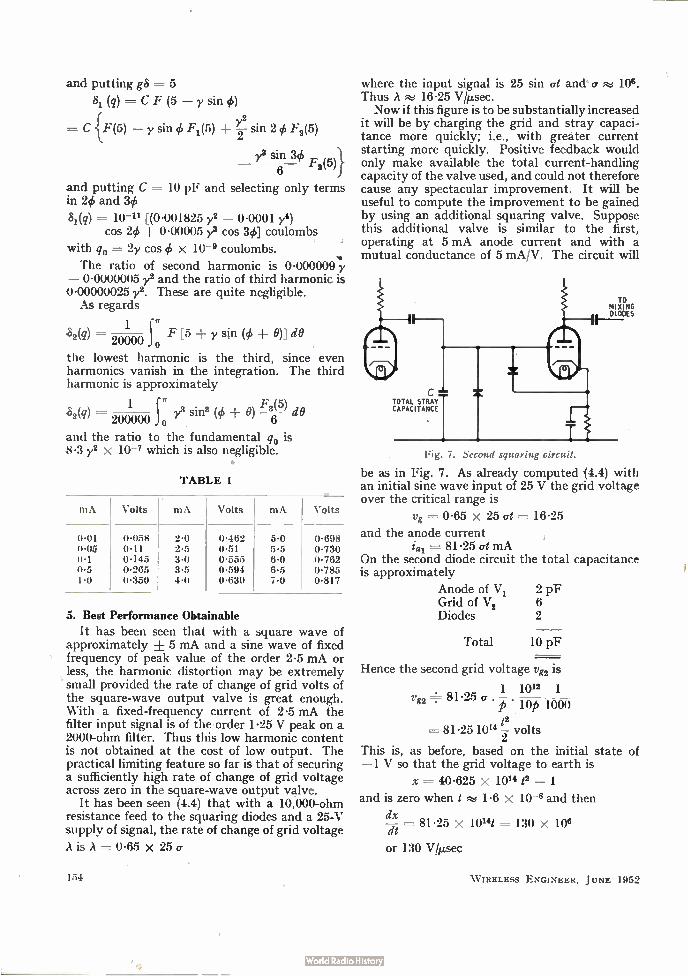
it will be by charging the grid and stray capaci-tance more quickly; i.e., with greater current starting more quickly. Positive feedback would only make available the total current-handling capacity of the valve used, and could not therefore cause any spectacular improvement. It will be useful to compute the improvement to be gained by using an additional squaring valve. Suppose this additional valve is similar to the first, operating at 5 mA anode current and with a mutual conductance of 5 mA/V. The circuit will
TO MIXING DIODES
TOTAL STRA1 CAPACITANCE
Fig. 7. Second squaring circtia.
be as in Fig. 7. As already computed (4.4) with an initial sine wave input of 25 V the grid voltage over the critical range is
Vg = 0.65 X 25 at --= 16.25
and the anode current = 81.25 at mA
On the second diode circuit the total capacitance is approximately
Anode of V1 2 pF Grid of V 2 6 Diodes 2
Total 10 pF
Hence the second grid voltage vg2 is
1 1012 1
vg2 81.25 a p • lop woo 12
= 81-25 10" volts
This is, as before, based on the initial state of -1 V so that the grid voltage to earth is
x = 40.625 x 10" t2 - 1
and is zero when t 1.6 x 10⁻⁸ and then
dx 81.25 x 10"/ = 130 x 108
or 130 Vlµsec
W IRELESS ENGINEER, JUNE 1952
compared with 16-25 Vb./sec on the first grid. Thus, other things being unchanged, an addi-
tional valve could give a reduction of distortion
in the ratio 16-25 130 or 0-125 or with fixed-frequency
current of 1 mA the second-harmonic ratio to fundamental would be
1 4 x 130 x 5
or < 0-05%
6. Conclusions Of the three methods discussed, namely
(1) Multiplication in a square-law device, (2) Addition and linear rectification of the
sum, (3) Addition of one component to a square
wave synchronous with the other com-ponent and linear rectification of the sum,
the last is by far the best. The output and free-dom from distortion obtained by this method with valve anode currents of only 5 mA would require signals of the order 100 mA if method 2 were used. Method 3 also results in reduced mixer noise and requires less filtration to remove h.f. components from the output. •
Acknowledgments The foregoing analysis was undertaken with
reference to a portable tone sourcel developed for use in room acoustics by the B.B.C. Engineering Research Department. The author is indebted to the Chief Engineer of
the B.B.C. for permission to publish this article.
REFERENCE C. G. Mayo and D. G. Beadle. "Equipment for Acoustic Measure-
ments," Electronic Engineering, October 1951, p. 368.
CATHODE-FOLLOWER OPERATION Transient and Steady-State Performance with a Capacitive Load
By A. J. Shimmins, B.E.E., B.Com. (EM.!. Engineering Development-Advanced Development.)
1. Introduction IT is proposed to give consideration to the operation of cathode-follower circuits with capacitive loads. In a previous paper' consider-
ation was given to the operation of these circuits under pulse and sawtooth conditions. It was shown that with a large capacitive load, grid current can flow for a short time, when a steep-fronted waveform is applied to the grid. This prevents complete isolation between the input circuit and the load, and makes the output volt-age of exponential form of time constant equal to the output impedance multiplied by the capaci-tance of the load.
In this paper it is proposed to give consideration • to methods of improving the performance of cathode-follower circuits both under steady-state and transient conditions and three approaches have been considered, viz:
(a) The use of an inductance in series with the capacitive load.
(b) The use of a filter circuit as the cathode load, based on the fact that a low-pass 7r-filter with a capacitance in parallel with
MS. accepted by the Editor, July 1951
W IRELESS ENGINEER, JUNE 1952
the input has a constant input impedance over a wide frequency band.
(c) The use of increased capacitance between grid and cathode effectively to transfer part of the cathode-load capacitance into the input circuit.
The main interest has been in attempting to improve the transient response of the cathode-follower, particularly by the use of inductive coupling circuits similar to those which have been successfully used to improve the performance of wideband amplifiers, but steady-state perform-ances, particularly the cases of a series inductance and an ideal filter load are also considered.
It is shown that with a simple series inductance, the 10-90% rise time of the output voltage is improved by a factor up to 1.5, with an over-shoot less than 5%. This is accompanied by a corresponding increase in the steady-state band-width. The presence of an inductance between cathode and anode load also modifies the cathode voltage waveform, resulting in a reduced flow of grid current if the grid is driven positive with a step-function input. With an ideal filter load in the cathode circuit,
the bandwidth under steady-state conditions is
155
increased, but the transient performance is diffi-cult to determine and experiments show that the overshoot is objectionable which, together with its relative complexity, makes the circuit of no practical value. The effect of the grid-cathode capacitance on the
transient performance is then considered, and,it is shown that with a step function input, the grid-cathode capacitance results in an initial step in the output voltage, followed by a subsequent exponential rise. The initial step can be increased by increasing the grid-cathode capacitance but this is accompanied by an exponentially decreas-ing input current to charge the grid-cathode capacitance, thus losing the high input impedance of the cathode-follower.
2. Equivalent Circuits and Superposition Integrals
2.1. Equivalent Circuit for Large Grid-Cathode Impedance
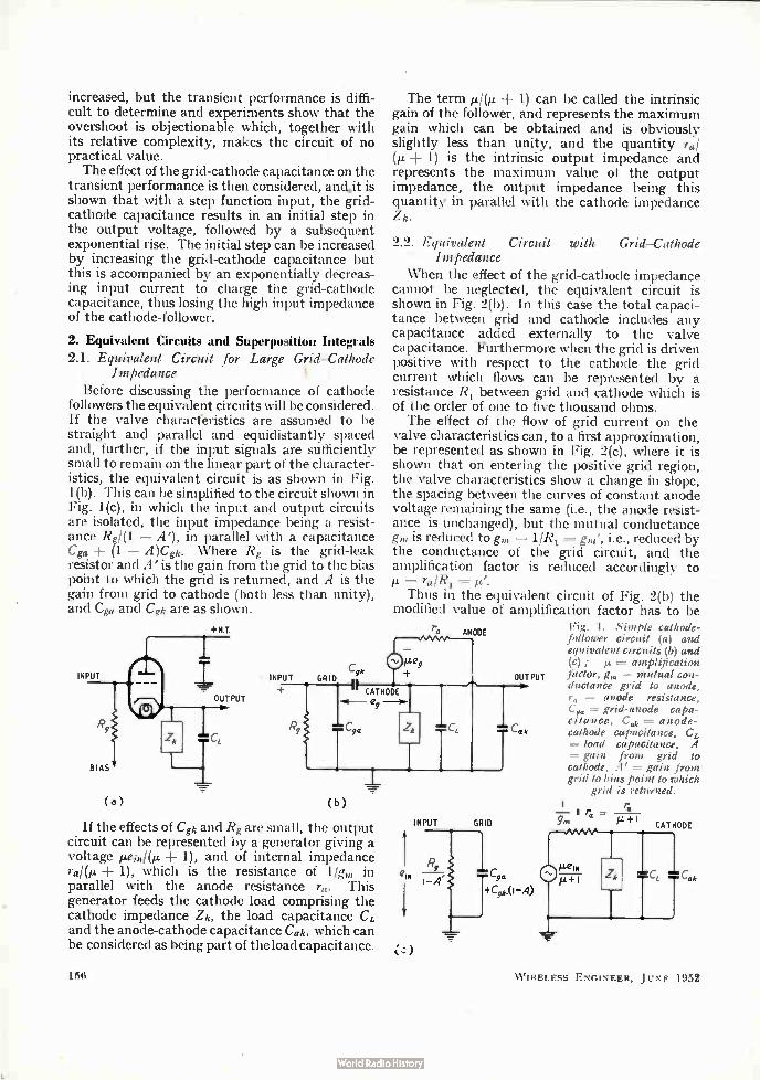
Before discussing the performance of cathode followers the equivalent circuits will be considered. If the valve characferistics are assumed to be straight and parallel and equidistantly spaced and, further, if the input signals are sufficiently small to remain on the linear part of the character-istics, the equivalent circuit is as shown in Fig. 1(b). This can be simplified to the circuit shown in Fig. 1(c), in which the input and output circuits are isolated, the input impedance being a resist-ance Rgl(1 — A'), in parallel with a capacitance Cga + (1 — A)Cgh. Where Rg is the grid-leak resistor and A' is the gain from the grid to the bias point to which the grid is returned, and A is the gain from grid to cathode (both less than unity), and Ce and Cgh are as shown.
+HI
INPUT
OUTPUT
BIAS
( a
INPUT CgA•
GRID
The term FRI.,. ± 1) can be called the intrinsic gain of the follower, and represents the maximum gain which can be obtained and is obviously slightly less than unity, and the quantity Tal + 1) is the intrinsic output impedance and
represents the maximum value of the output impedance, the output impedance being this quantity in parallel with the cathode impedance Zk.
2.2. Equivalent Circuit with Grid-Cathode Impedance
When the effect of the grid-cathode impedance cannot be neglected, the equivalent circuit is shown in Fig. 2(b). In this case the total capaci-tance between grid and cathode includes any capacitance added externally to the valve capacitance. Furthermore when the grid is driven positive with respect to the cathode the grid current which flows can be represented by a resistance R1 between grid and cathode which is of the order of one to five thousand ohms. The effect of the flow of grid current on the
valve characteristics can, to a first approximation, be represented as shown in Fig. 2(c), where it is shown that on entering the positive grid region, the valve characteristics show a change in slope, the spacing between the curves of constant anode voltage remaining the same (i.e., the anode resist-ance is unchanged), but the mutual conductance gm is reduced to gm — 11R1= gm ', i.e., reduced by the conductance of the grid circuit, and the amplification factor is reduced accordingly to — 7a/R1 = Thus in the equivalent circuit of Fig. 2(b) the
modified value of amplification factor has to be
lae2
ra ANODE
CATHODE e
If the effects of Cgh and Rg are small, the output circuit can be represented by a generator giving a voltage iLein/(µ + 1), and of internal impedance ra/(µ ± 1), which is the resistance of 1/gm in parallel with the anode resistance Ta. This generator feeds the cathode load comprising the cathode impedance Zk, the load capacitance CL and the anode-cathode capacitance Cak, which can be considered as being part of the load capacitance.
156
eIN
íz)
INPUT
:C,
GRID
OUTPUT
Fig. 1. Simple cathode-follower circuit (a) and equivalent circuits (b) and (c) ; = amplification factor, g„, = mutual con-ductance grid to anode, = anode resistance,
C‘,„ = grid-anode capa-citance, Ce = anode-cathode capacitance, CL = load capacitance, A = gain from grid to cathode, A' -- gain from grid to bias point to which
grid is returned.
—7, II eg
:
W IRELESS ENGINEER, JUNE 1952
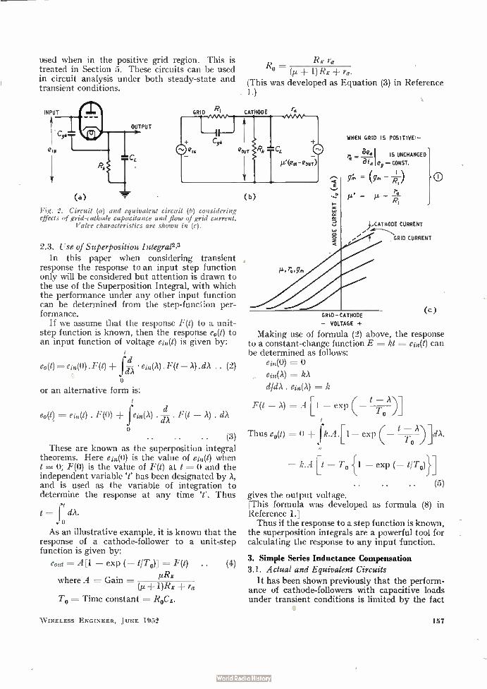
RK ra used when in the positive grid region. This is treated in Section 5. These circuits can be used R = (it + 1) RE + ra.
in circuit analysis under both steady-state and (This was developed as Equation (3) in Reference transient conditions. . 1.)
(b)
Fig. 2. Circuit (a) and equivalent circuit (b) considering effects of grid-cathode capacitance and flow of grid current.
Valve characteristics are shown in (c).
2.3. Use of Superposition Integral2,3 In this paper when considering transient
response the response to an input step function only will be considered but attention is drawn to the use of the Superposition Integral, with which the performance under any other input function can be determined from the step-function per-formance.
If we assume that the response F(t) to a unit-step function is known, then the response eo(t) to an input function of voltage ein(t) is given by:
d e(A) ein(0). F(1) ±f — • in(X) .F(t — A) . dA. (2)
dA o
or an alternative form is:
d e0(t) = e,1(t) . F(0) ± Je(A) . . F(t — A) . ciA
o • • • • • • (3)
These are known as the superposition integral theorems. Here en(0) is the value of e(t) when t = 0; F(0) is the value of F(t) at t = 0 and the independent variable ̀ t' has been designated by A, and is used as the variable of integration to determine the response at any time T. Thus
t = ft dA. o
As an illustrative example, it is known that the response of a cathode-follower to a unit-step function is given by:
eout =- A[1 — exp (— tiro)] =-- F(t) (4)
where A = Gain = eeRK (et 1)RE ra
To = Time constant -- RoCt.
W IRELESS ENGINEER, JUNE 1952
WHEN GRID IS POSITIVE:—
r = aea I IS UNCHANGED
a 8z, 09 CONST.
ANODE CURRENT
(mA)
GRID—CATHODE
— VOLTAGE +
Making use of formula (2) above, the response to a constant-change function E =. kt ---- ein(t) can be determined as follows:
en(0) =
ein(A)
dIdX e(A) = k
F(t — A) -- A[1 — exp A)]
Thus e0(t) = O + fk.A — exp ToA)]dA.
= k.A[t — To {1 — exp ( — t/T0)}1
• • (5) gives the output voltage.
his formula was developed as formula (8) in Reference 1.] Thus if the response to a step function is known,
the superposition integrals are a powerful tool for calculating the response to any input function.
3. Simple Series Inductance Compensation
3.1. Actual and Equivalent Circuits It has been shown previously that the perform-
ance of cathode-followers with capacitive loads under transient conditions is limited by the fact
),CATHODE CURRENT
GRID CURRENT
(c)
157
O
that the load capacitance has to be charged through the effective output impedance of the cathode-follower. Consequently, the cathode voltage cannot rise rapidly enough compared with the grid voltage with the result that grid current can flow during part of the rise time of the cathode voltage. One obvious method of limiting this effect is to
place an inductance between the cathode and the load capacitance, thus 'permitting the cathode
ra
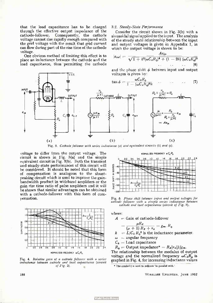
3.2. Steady-State Performance
Consider the circuit shown in Fig. 3(b) with a sinusoidal signal applied to the input. The analysis of the steady state relationship between the input and output voltages is given in Appendix 1, in which the output voltage is shown to be:
A ein leouti —
k2(c0CL/20)4 ± (1 — 2k) (coCER0)2
• • • • • • (6) and the phase shift q!. between input and output voltages is given by:
coCER0 tan 4, —
1 — (cuCLR0)2k •
Rk = Ro
• (7) •
R i-1-7FT ,
= Aen,
(a) (b) . (c)
Fig. 3. Cathode follower with series inductance (a) und equivalent circuits (b) and (c).
voltage to differ from the output voltage. The circuit is shown in Fig. 3(a) and the simple equivalent circuit in Fig. 3(b). Both the transient and steady-state performances of this circuit will be considered. It should be noted that this form of compensation is analogous to the shunt-peaking circuit which is used to improve the gain-bandwidth product in wideband amplifiers or the gain rise time ratio of pulse amplifiers and it will be shown that similar advantages can be obtained with a cathode-follower with this form of com-pensation.
III 0-5
25
k•O
02 04 Od 00 Id I 2 14
NORMALIZED FREQUENCY cledia.
18 2.0 22 24
Fig. 4. Relative gain of a cathode follower with a series inductance between cathode and load capacitance (circuit
of Fig. 3). •
158
NORMALIZED FREQUENCY 0CLR.
0 0.2 04 06 08 1.0 I 2 1.4 Id 18 20 22
te, 40 at oa o
80
24
10 120
-160
200
0.25
0.5
1.0
Ill
Fig. 5. Phase shift between input and output voltages for cathode follower with a simple series inductance between
cathode and load capacitance (circuit of Fig. 3).
where: A = Gain of cathode-follower
µRE
k = LICL R02 is the inductance parameter. angular frequency
CL — Load capacitance Ro = Output impedance* = REIVE111/gm.
The relationship between the modulus of output voltage and the normalized frequency WC/R0 is graphed in Fig. 4, for increasing inductance values
• The symbol lis used to indicate 'in parallel with.'
W IRELESS ENGINEER, JUNE 1952
corresponding to k = 0.25; k = 0.5; k = 1 and also for the case of no inductance (k = 0).
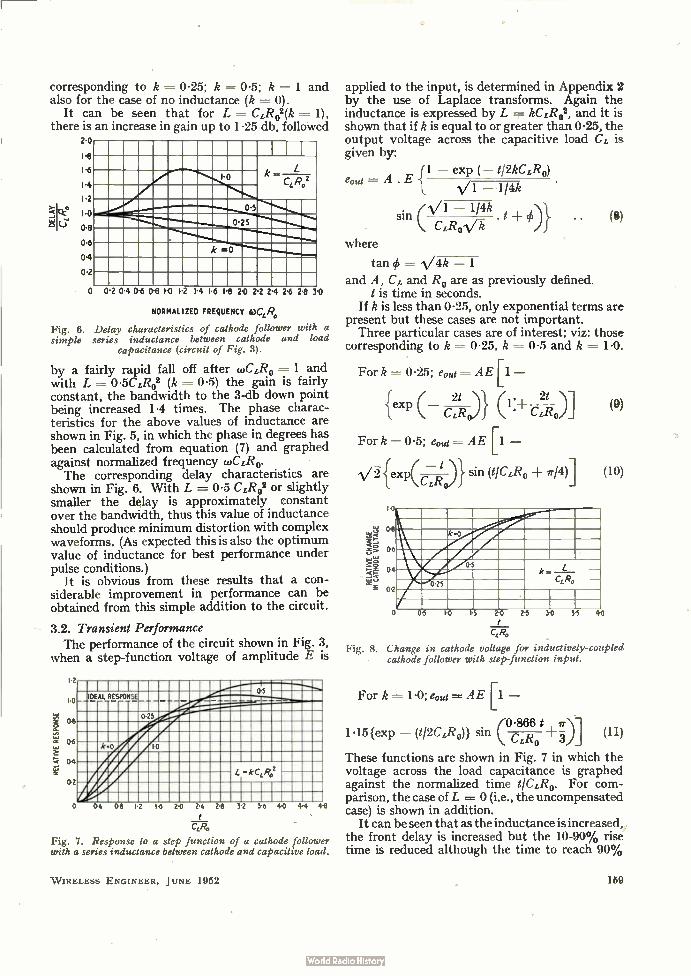
It can be seen that for L = CLR02(k = 1), there is an increase in gain up to 1.25 db, followed
ck°
2.
I.
1.
1
I.
0.
o
,
,
--",.......i.z......... k L
CLR.,2 .
1
0.5
i k =0
.
!
0 0.2 04 06 08 1-0 12 14 1.6 18 20 2 2 24 2.6 2.8 3•0
NORMALIZED FREQUENCY 4.1CLR,,
Fig. 6. Delay characteristics of cathode follower with a simple series inductance between cathode and load
capacitance (circuit of Fig. 3).
by a fairly rapid fall off after wCzRo = 1 and with L = 0-5CLR02 (k 0.5) the gain is fairly constant, the bandwidth to the 3-db down point being increased 1-4 times. The phase charac-teristics for the above values of inductance are shown in Fig. 5, in which the phase in degrees has been calculated from equation (7) and graphed against normalized frequency cyCLRo. The corresponding delay characteristics are
shown in Fig. 6. With L = 0-5 CI,R02 or slightly smaller the delay is approximately constant over the bandwidth, thus this value of inductance should produce minimum distortion with complex waveforms. (As expected this is also the optimum value of inductance for best performance under pulse conditions.)
It is obvious from these results that a con-siderable improvement in performance can be obtained from this simple addition to the circuit.
3.2. Transient Performance The performance of the circuit shown in Fig. 3,
when a step-function voltage of amplitude E is
ERLATIVE ONSRESPE
I 2
1-0
0-8
0-0
04
0-2
IDEAL RESPONSE_ 0-5
0-25
k o 1-0
L -kCIR02
0 04 0-8 1 2 I 6 2-0 24
CLR.
Fig. 7. Response to a step function of a cathode follower with a series inductance between cathode and capacitive load.
2-8 32 III 36 4-0 44 4.8
W IRELESS ENGINEER, JUNE 1952
applied to the input, is determined in Appendix 2 by the use of Laplace transforms. Again the inductance is expressed by L kC£R02, and it is shown that if k is equal to or greater than 0.25, the output voltage across the capacitive load Cz is given by:
{1 — exp ( — tl2kCz120) ema = A . E
--114k
(VI — 1/4k sin CLRoVk
where
tan = -V4k — 1
and A, Ch and Ro are as previously defined. t is time in seconds.
If k is less than 0-25, only exponential terms are present but these cases are not important. Three particular cases are of interest; viz: those
corresponding to k = 0.25, k = 0.5 and k = 1.0.
(9)
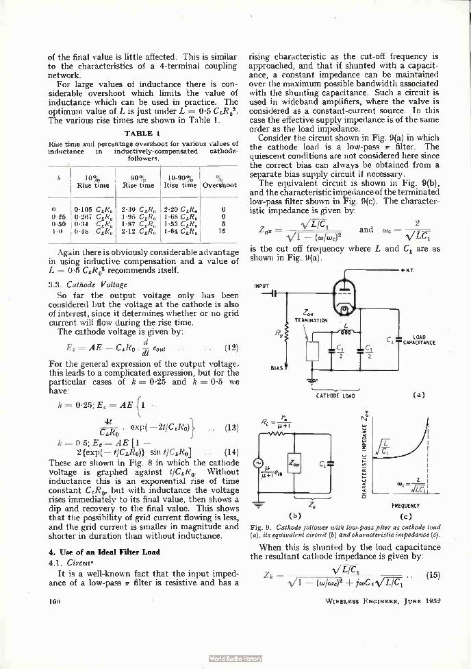
of the final value is little affected. This is similar to the characteristics of a 4-terminal coupling network.
For large values of inductance there is con-siderable overshoot which limits the value of inductance which can be used in practice. The optimum value of L is just under L = 0.5 CcR02. The various rise times are shown in Table 1.
TABLE 1
Rise time and percentage overshoot for various values of inductance in inductively-compensated cathode-
followers.
h
0 0.25 0•50 1.0
10% Rise time
90% Rise time
0.105 Ce, 0.267 Ceo 0.34 CLR, 0.48 Ce,
2.30 Ce, 1.95 CLR, 1.87 Ceo 2.12 Ce,
10-90% Rise time
2.20 Cep 1.68 CLR, 1-53 CLR, 1-64 CzRo
°/o Overshoot
o o 6 16
Again there is obviously considerable advantage in using inductive compensation and a value of L = 0.5 CLR02 recommends itself.
3.3. Cathode Voltage So far the output voltage only has been
considered but the voltage at the cathode is also of interest, since it determines whether or no grid current will flow during the rise time. The cathode voltage is given by:
d Ec = AE — CzRo
dt . . (12)
For the general expression of the output voltage, this leads to a complicated expression, but for the particular cases of k = 0.25 and k = 0.5 we have:
k = 0.25; Ec = AE {1 —
41 Cell) . exp( — 2t/CLR0)} (13)
k = 0.5; E, = AE [1 — 2 {exp( — t/CLR0)} sin t/CLR4 .. (14)
These are shown in Fig. 8 in which the cathode voltage is graphed against t/CLRo. Without inductance this is an exponential rise of time constant CLR0, but with inductance the voltage rises immediately to its final value, then shows a dip and recovery to the final value. This shows that the possibility of grid current flowing is less, and the grid current is smaller in magnitude and shorter in duration than without inductance.
4. Use of an Ideal Filter Load 4.1. Circus.
It is a well-known fact that the input imped-ance of a low-pass sr filter is resistive and has a
160
rising characteristic as the cut-off frequency is approached, and that if shunted with a capacit-ance, a constant impedance can be maintained over the maximum possible bandwidth associated with the shunting capacitance. Such a circuit is used in wideband amplifiers, where the valve is considered as a constant-current source. In this case the effective supply impedance is of the same order as the load impedance.
Consider the circuit shown in Fig. 9(a) in which the cathode load is a low-pass or filter. The quiescent conditions are not considered here since the correct bias can always be obtained from a separate bias supply circuit if necessary. The equivalent circuit is shown in Fig. 9(b),
and the characteristic impedance of the terminated low-pass filter shown in Fig. 9(c). The character-istic impedance is given by:
Zet V Lic
— (w/wc)2 and
2
is the cut off frequency where L and C1 are as shown in Fig. 9(a).
INPUT
BIAS
+
Zo„
TERMINATION
CATHODE LOAD
(b)
CHARACTERISTIC IMPEDANCE Zo
ff
+N.T.
LOAD CAPACITANCE
(a)
FREQUENCY
(C)
Fig. 9. Cathode follower with low-pass filter as cathode load (a), its equivalent circuit (b) and characteristic impedance (c).
When this is shunted by the load capacitance the resultant cathode impedance is given by:
LICi Z — (w/wc)2 jtoCLV L/CI. (15)
W IRELESS ENGINEER, JUNE 1952
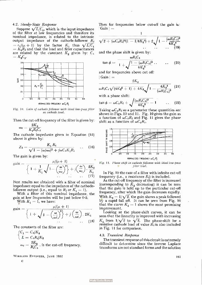
4.2. Steady-State Response Suppose /L/C1, which is the input impedance
of the filter at low frequencies and therefore its nominal impedance, is related to the intrinsic output impedance of the cathode-follower Ri =ra/(i.c + 1) by the factor K1 thus \/L/C1 KIRi and that the load and filter capacitances
are related by the donstant K2 given by: C K2Ci.
0 I
2 , 5
I k2 »00 4
3
di
,2 CL
l 0 0.5 10 IS 20 21 30
NORMALIZED FREQUENCY 0CLRi
Fig. 10. Gain of cathode follower with ideal low-pass filter as cathode load.
35 40
Then the cut-off frequency of the filter is given by:
2K0 KiRiCL
The cathode impedante given in Equation (15) above is given by:
K1 Ri Z k =
Vi — (colcoo)2 jcuCLKIRi
The gain is given by:
gain = 141(e+ 1)
(16)
{ 1 ± K --1 /1— (V-1)-.i2} 1 cic
(17)
Best results are obtained with a filter of nominal impedance equal to the impedance of the cathode-follower output (i.e., equal to Ri or K1 = 1). With a filter of this nominal impedance, the
gain at low frequencies will be just below 0.5. With K1 = 1, we have:
gain —
•
+
2K0
(18) The constants of the filter are:
fC1 = CL/K2
1 L = CLI?s1K2
2K0 . coc = . is the cut-off frequency.
Then for frequencies below cut-off the gain is: I Gain I
1
V2 (c0CLRi)2(1 — 1/4K23) + 2J1
and the phase shift is given by:
cuRiCL
(c.RiCL)2 4K20 . . (19)
tan ck = 1 — (c.RiCL)2 .. (20) 4K20
and for frequencies above cut off:
I Gain I
2K0
CORiCLVel/C22 1) ± 4K2,%/1 (COReL) 2
4K22 (21)
with a phase shift:
tan = c0CLRi + ,‘/(03RiCL) 2 1
4K22
Taking coCLRi as a parameter these quantities are shown in Figs. 10 and 11. Fig. 10 gives the gain as a function of cuCLRi and Fig. 11 gives the phase shift as a function of (»CLRi.
tro I
I 2
04
6
.. (22)
di 2
O
kz•oo
05 le 15 20 25 30 35 40
NORMALIZED FREQUENCY 0CLRi
Fig. 11. Phase shift in cathode follower with ideal low-pass filter load.
In Fig. 10 the case of a filter with infinite cut-off frequency (i.e., a resistance Ri) is included. As the cut-off frequency of the filter is increased
(corresponding to K2 decreasing) it can be seen that the gain is held up to the particular cut-off frequency, after which the gain decreases rapidly. With K2= 1107 the gain shows a peak followed 1:$2 a rapid fall off. It can be seen from Fig. 10 that the curve K2 = 1 shows the most promising improvement.
Looking at the phase-shift curves, it can be seen that the linearity is improved with increasing K2 from 1/V-2- to The phase-shift for a resistive cathode load of value Ri is also included in Fig. 11 for comparison.
4.3. Transient Response The transient response of this circuit is extremely
difficult to determine since the inverse Laplace transforms are not standard forms and the solution
W IRELESS ENGINEER, JUNE 1952 161
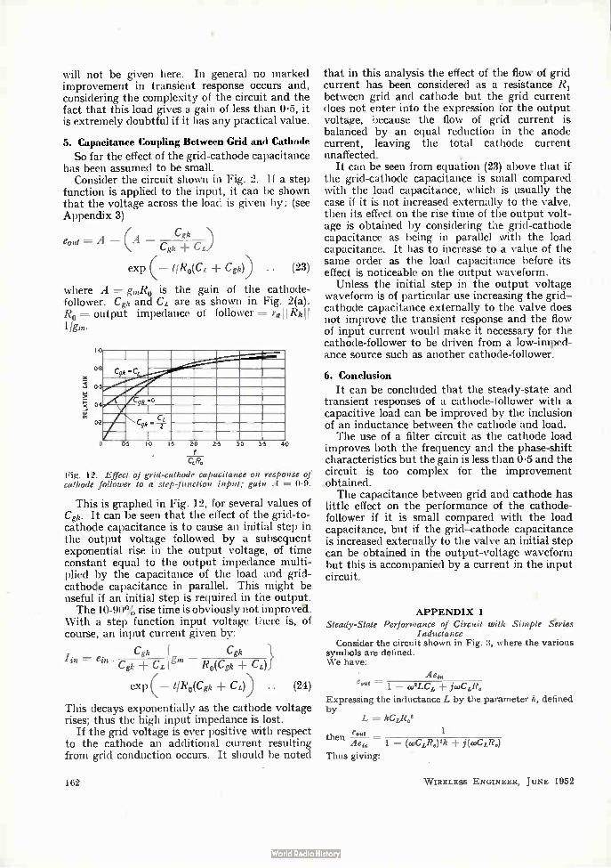
will not be given here. In general no marked improvement in transient response occurs and, considering the complexity of the circuit and the fact that this load gives a gain of less than 0-5, it is extremely doubtful if it has any practical value.
5. Capacitance Coupling Between Grid and Cathode
So far the effect of the grid-cathode capacitance has been assumed to be small.
Consider the circuit shown in Fig. 2. If a step function is applied to the input, it can be shown that the voltage across the load is given by: (see Appendix 3)
eout = A — (A Cgk
Cgk C L.)
exp (— t/Ro(CL + Co)) .. (23)
where A = g,120 is the gain of the cathode-follower. Co and CL are as shown in Fig. 2(a). Ro = output impedance of follower = TaI I Rh!! ligns•
RELA
TIVE
GAIN
10
04
04
0.2
9C °
s Cse, -
o 05 lO 15 24 25 34 35 413
QR.
Fig. 12. Effect of grid-cathode capacitance on response of cathode follower to a step-function input; gain A = 0.9.
This is graphed in Fig. 12, for several values of Cgk. It can be seen that the effect of the grid-to-cathode capacitance is to cause an initial step in the output voltage followed by a subsequent exponential rise in the output voltage, of time constant equal to the output impedance multi-plied by the capacitance of the load and grid-cathode capacitance in parallel. This might be useful if an initial step is required in the output. The 10-90% rise time is obviously not improves.
With a step function input voltage there is, of course, an input current given by:
Cgk Cgk ein .
Cgk CL gm Ro(Ce CL)}
exp (— t/Ro(Cgk CL)) .. (24)
This decays exponentially as the cathode voltage rises; thus the high input impedance is lost.
If the grid voltage is ever positive with respect to the cathode an additional current resulting from grid conduction occurs. It should be noted
162
that in this analysis the effect of the flow of grid current has been considered as a resistance R1 between grid and cathode but the grid current does not enter into the expression for the output voltage, because the flow of grid current is balanced by an equal reduction in the anode current, leaving the total cathode current unaffected.
It can be seen from equation (23) above that if the grid-cathode capacitance is small compared with the load capacitance, which is usually the case if it is not increased externally to the valve, then its effect on the rise time of the output volt-age is obtained by considering the grid-cathode capacitance as being in parallel with the load capacitance. It has to increase to a value of the same order as the load capacitance before its effect is noticeable on the output waveform.
Unless the initial step in the output voltage waveform is of particular use increasing the grid— cathode capacitance externally to the valve does not improve the transient response and the flow of input current would make it necessary for the cathode-follower to be driven from a low-imped-ance source such as another cathode-follower.
6. Conclusion It can be concluded that the steady-state and
transient responses of a cathode-follower with a capacitive load can be improved by the inclusion of an inductance between the cathode and load. The use of a filter circuit as the cathode load
improves both the frequency and the phase-shift characteristics but the gain is less than 0.5 and the circuit is too complex for the improvement obtained. The capacitance between grid and cathode has
little effect on the performance of the cathode-follower if it is small compared with the load capacitance, but if the grid—cathode capacitance is increased externally to the valve an initial step can be obtained in the output-voltage waveform but this is accompanied by a current in the input circuit.
APPENDIX 1
Steady-State Performance of Circuit with Simple Aries Inductance
Consider the circuit shown in Fig. 3, where the various symbols are defined. We have:
Aeo,
— 1 — co2LCy jcuCLR.
Expressing the inductance L by the parameter k, defined by
L = kCLR.2
then d — 1 Aei„ 1 — (wCyR0)2k j(coCee)
Thus giving:
W IRELESS ENGINEER, JUNE 1952
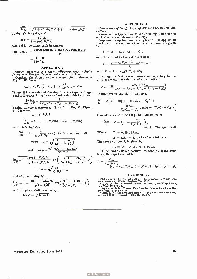
emit Aed„ k2(wCLR.)4 + (1 — 21i)(wCLR.)2
as the relative gain, and
coCLR, tan =
1 — (cuCLR,)2k.
where q9 is the phase shift in degrees
Phase shift in radians at frequency co'
1
The delay
4, 1r = 180 "ro
APPENDIX 2
Transient Response of a Cathode-Follower with a• Series Inductance Between Cathode and Capacitive Load.
Consider the circuit and equivalent circuit shown in Fig. 3. We have:
d2 e.„, CLR„. . eout + LC (-112 e„„t = A.E
Where E is the value of the step-function input voltage. Taking Laplace Transforms of both sides this becomes:
1 ce ea.' AE LCL(p2 pRoIL 1/LCL)
Taking inverse transforms. (Transform No. 51, Pipes', p. 134) when
L = CLR0214
= 1 — (1 ± IR,,/2L) . exp (— 11412M AE
or if L > CL.R.214
e 1 "t 1 AE coVr..exP (—/R./2Z.) sin (wt e)
where to ,s/ 1 (R.\2
LC 1U21.) z
and tan S — V1ILCL — (R.1242 q (R,,/2L)
.exp(— Rot)/2L
AE CLR.214L sin (IN/ reI—A. (1:;.)2+
tan = 4L 1 CLRo2
Putting L = W eR.2
eost exp( — sin (W1 — 1/4k .. (1,)
AE V1— 114k 1ViCLR.
and:the phase shift is given by:
tan e = 4k — 1
APPENDIX 3
Determination of the effect of Capacitance between Grid and Cathode.
Consider the typical circuit shown in Fig. 2(a) and the equivalent circuit shown in Fig. 2(b).
Suppose a step function of amplitude E is applied to the input, then the current in the input circuit is given by:
(E — e,„")(11R,± pc„)
and the current in the valve circuit is:
r.11?1)(1E e.«,) e..,
and /2 = e„„,(1/R1 pcL)
Adding the first two equations and equating to the third equation gives the transform equation:
»fro PC.k e, = E {elr. ± 1/r, 1/R1 p(CL C,k)}
Taking inverse transforms we have:
= A[1 — exp { — t/Ro(CL, Ce )}
R „Co . exp — t/Ro(CL Co )}
Ro(C,k CL)
(Transforms Nos. 7 and 8 p. 130, Reference 4)
e„„g = A — (A Co E Ce + Cy) •
exp {— t/R,(C,k CL))
Where R. = Rk Ir,,I1 llg„,.
A = g„,R. = gain of cathode follower.
The input current I, is given by:
(E — e„.,)(11R, pC,k).
If the grid is never positive, so that R1 is infinitely large, the input current is:
C k — e Ce CL
{g,„ — C0 112.(Cfm CL)} exp { — t/Ro(C,k Cy)}
REFERENCES
1 Shimmins, A. J. "Cathode-Follower Performance, Pulse and Saw. tooth Conditions," Wireless Engineer, Dec. 1950.
Vannevar Bush. "Operational Circuit Analysis," John Wiley & Sons, New York, 1929, Ch. 6.
Arguirnbau, L. B. "Vacuum Tube Circuits," John Wiley & Sons, New York, 1948, pp. 153 and 590.
Pipes, L. A. "Applied Mathematics for Engineers and Physicists," McGraw-Hill Book Company, 1946, pp. 128-137.
W IRELESS ENGINEER, JUNE 1952 163
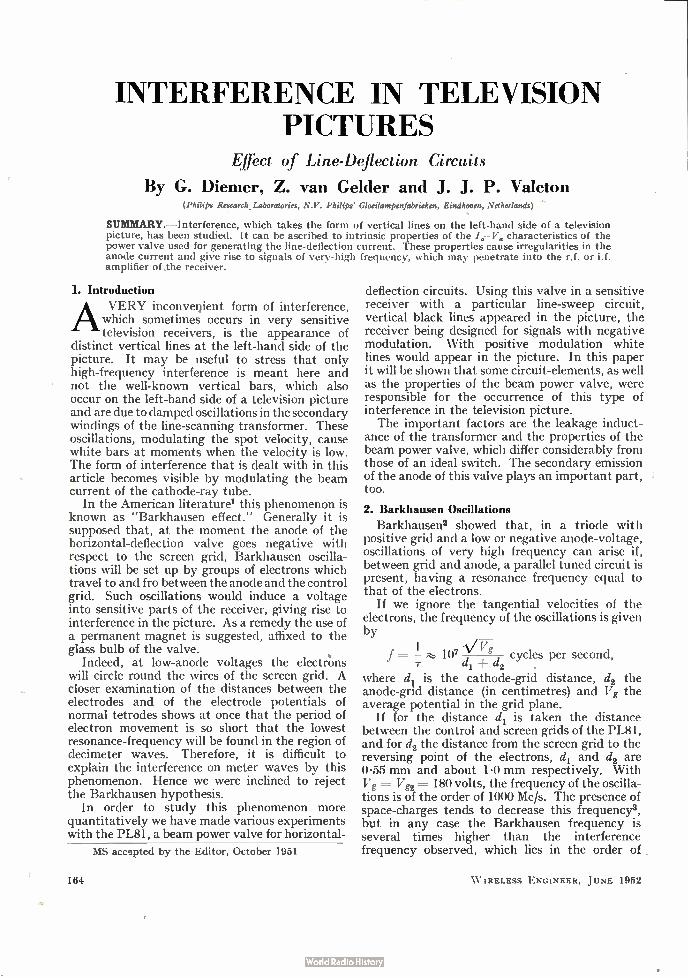
INTERFERENCE IN TELEVISION PICTURES
Effect of Line-Deflection Circuits
By G. Diemer, Z. van Gelder and J. J. P. Valeton (Philips Research _Laboratories, N.V. Philips' Gloeilampenfabrieken, Eindhoven, Netherlands)
81:1161rdARY. —Interference, which takes the form of vertical lines on the left-hand side of a television picture, has been studied. It can be ascribed to intrinsic properties of the characteristics of the power valve used for generating the line-deflection current. These properties cause irregularities in the anode current and give rise to signals of very-high frequency, which may penetrate into the r.f. or if. amplifier of .the receiver.
1. Introduction
AVERY inconvenient form of interference, which sometimes occurs in very sensitive television receivers, is the appearance of
distinct vertical lines at the left-hand side of the picture. It may be useful to stress that only high-frequency interference is meant here and not the well-known vertical bars, which also occur on the left-hand side of a television picture and are due to damped oscillations in the secondary windings of the line-scanning transformer. These oscillations, modulating the spot velocity, cause white bars at moments when the velocity is low. The form of interference that is dealt with in this article becomes visible by modulating the beam current of the cathode-ray tube.
In the American literature' this phenomenon is known as "Barkhausen effect." Generally it is supposed that, at the moment the anode of the horizontal-deflection valve goes negative with respect to the screen grid, Barkhausen oscilla-tions will be set up by groups of electrons which travel to and fro between the anode and the control grid. Such oscillations would induce a voltage into sensitive parts of the receiver, giving rise to interference in the picture. As a remedy the use of a permanent magnet is suggested, affixed to the glass bulb of the valve.
Indeed, at low-anode voltages the electrons will circle round the wires of the screen grid. A closer examination of the distances between the electrodes and of the electrode potentials of normal tetrodes shows at once that the period of electron movement is so short that the lowest resonance-frequency will be found in the region of decimeter waves. Therefore, it is difficult to explain the interference on meter waves by this phenomenon. Hence we were inclined to reject the Barkhausen hypothesis.
In order to study this phenomenon more quantitatively we have made various experiments with the PL81, a beam power valve for horizontal-
MS accepted by the Editor, October 1951
164
deflection circuits. Using this valve in a sensitive receiver with a particular line-sweep circuit, vertical black lines appeared in the picture, the receiver being designed for signals with negative modulation. With positive modulation white lines would appear in the picture. In this paper it will be shown that some circuit-elements, as well as the properties of the beam power valve, were responsible for the occurrence of this type of interference in the television picture. The important factors are the leakage induct-
ance of the transformer and the properties of the beam power valve, which differ considerably from those of an ideal switch. The secondary emission of the anode of this valve plays an important part, too.
2. Barkhausen Oscillations
Barkhausen2 showed that, in a triode with positive grid and a low or negative anode-voltage, oscillations of very high frequency can arise if, between grid and anode, a parallel tuned circuit is present, having a resonance frequency equal to that of the electrons.
If we ignore the tangential velocities of the electrons, the frequency of the oscillations is given by
\/Fg f = -1 107 dl d2 cycles per second,
• where d1 is the cathode-grid distance, d2 the anode-grid distance (in centimetres) and Vg the average potential in the grid plane.
If for the distance d1 is taken the distance between the control and screen grids of the PL81, and for d2 the distance from the screen grid to the reversing point of the electrons, d, and d2 are 0.55 mm and about 1.0 mm respectively. With Vg = Vg2 = 180 volts, the frequency of the oscilla-tions is of the order of 1000 Mc/s. The presence of space-charges tends to decrease this frequency3, but in any case the Barkhausen frequency is several times higher than the interference frequency observed, which lies in the order of
W IRELESS ENGINEER, JUNE 1952
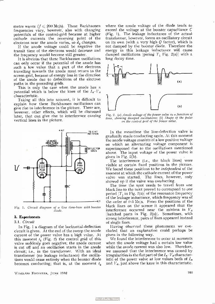
metre waves (f 200 Mc/s). These Barkhausen frequencies vary, however, also with changing potentials of the control-grid because at higher cathode currents the reversing point of the electrons near the anode varies, so d2 changes.
If the anode voltage could be negative the transit time of the electrons would decrease and the frequency would become still greater.
It is obvious that these Barkhausen oscillations can only occur if the potential of the anode has such a low value that a part of the electrons travelling towards the anode must return to the screen-grid, because of energy loss in the direction of the anode due to deflections of the electron paths in the preceding grids.
This is only the case when the anode has a potential which is below the knee of the /a—Va characteristic. Taking all this into account, it is difficult to
explain how these Barkhausen oscillations can give rise to interference in the picture. There are, however, other effects, which will be discussed later, that can give rise to interference causing vertical lines in the picture.
Fig.
LEAKAGE INDUCTANCE
1. Circuit diagram
+ H T TO E HI RFC TIFIER
DEFLECTOR COILS
H. T
of a line time-base with booster diode.
3. Experiments
3.1. Circuit In Fig. 1 a diagram of the horizontal-deflection
circuit is given. At the end of the sweep the anode current of the power valve has a high value. At this moment 11 (Fig. 2) the control grid of this valve suddenly goes negative, the anode current is cut off and an oscillation starts in the anode circuit; i.e., in the transformer. With an ideal transformer (no leakage inductance) the oscilla-tions would cease entirely when the booster diode becomes conducting; that is, at the moment t2
W IRELESS ENGINEER, JUNE 1952
where the anode voltage of the diode tends to exceed the voltage at the booster capacitance C (Fig. 1). The leakage inductance of the actual transformer, however, forms an oscillatory circuit on its own (with a very high Q factor), which is not damped by the booster diode. Therefore the energy in this leakage inductance will cause damped oscillations [period T1 Fig. 2(a)] with a long decay time.
(b)
Fig. 2. ve) Anode voltage of the power valve as a function of time, showing damped oscillations; (b) Shape of the pulse
on the control grid of the power valve.
In the meantime the line-deflection valve is gradually made conducting again. At this moment the anode voltage consists of a low positive voltage on which an alternating voltage component is superimposed due to the oscillations mentioned above. The input voltage of the power valve is given in Fig. 2(b). The interference (i.e., the black lines) were
visible at certain fixed positions in the picture. We found these positions to be independent of the moment at which the cathode current of the power valve was started. The lines, however, only showed up if the valve was conducting. The time the spot needs to travel from one
black line to the next proved to correspond to one period [T1 in Fig. 2(a)] of the resonance frequency of the leakage inductance, which frequency was of the order of 0.5 Mc/s. From the positions of the black lines on the screerr it appeared that the interference occurred near the minima in Va [hatched parts in Fig. 2(a)]. Sometimes, with strong interference, pairs of lines appeared instead of single lines. Having observed these phenomena we con-
cluded that an explanation could perhaps be given in the following way. We found the interference to occur at moments
when the anode voltage had a certain low value while the anode current was also low. Therefore, we assumed that the interference was caused by irregularities in the flat part of the /a—Va character-istic of the power valve at low values both of /a and Va, just above the knee in this characteristic.
165
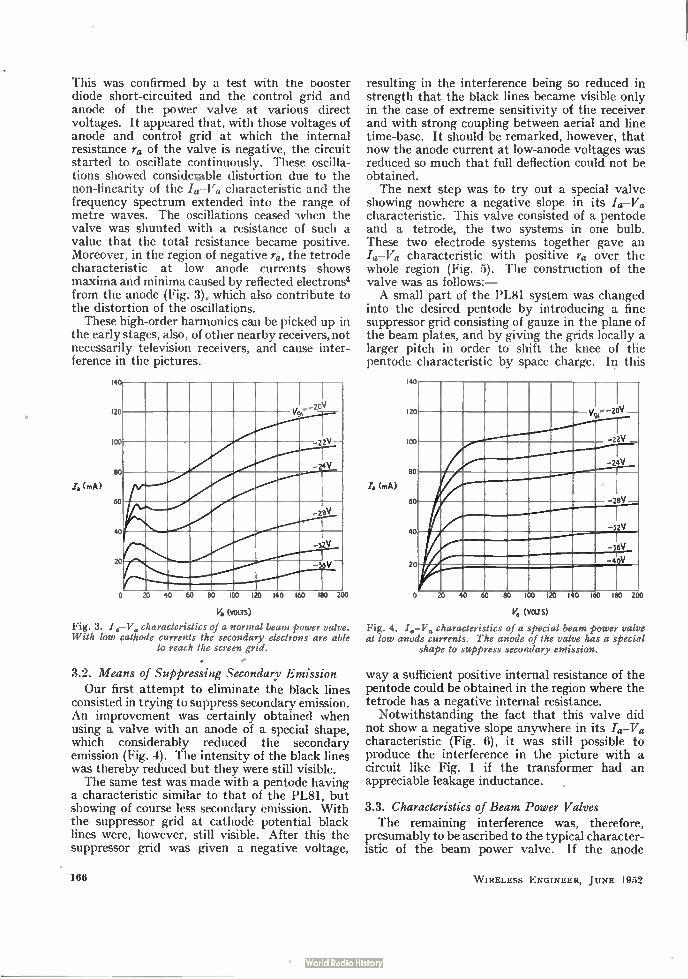
This was confirmed by a test with the booster diode short-circuited and the control grid and anode of the power valve at various direct voltages. It appeared that, with those voltages of anode and control grid at which the internal resistance ra of the valve is negative, the circuit started to oscillate continuously. These oscilla-tions showed considebable distortion due to the non-linearity of the /a-Va characteristic and the frequency spectrum extended into the range of metre waves. The oscillations ceased when the valve was shunted with a resistance of such a value that the total resistance became positive. Moreover, in the region of negative ra, the tetrode characteristic at low anode currents shows maxima and minima caused by reflected electrons.' from the anode (Fig. 3), which also contribute to the distortion of the oscillations. These high-order harmonics can be picked up in
the early stages, also, of other nearby receivers, not necessarily television receivers, and cause inter-ference in the pictures.
(A)
,, —20V 20 vg,
.-22V
—24V
00
80
60
—24V
40
—32V
20
0 20 40 60 80 100 120 140 160 180 200
Va (vous)
Fig. 3. I,,—V„ characteristics of a normal beam power valve. With low cathode currents the secondary electrons are able
to reach the screen grid.
3.2. Means of Suppressing Secondary Emission Our first attempt to eliminate the black lines
consisted in trying to suppress secondary emission. An improvement was certainly obtained when using a valve with an anode of a special shape, which considerably reduced the secondary emission (Fig. 4). The intensity of the black lines was thereby reduced but they were still visible. The same test was made with a pentode having
a characteristic similar to that of the PL81, but showing of course less secondary emission. With the suppressor grid at cathode potential black lines were, however, still visible. After this the suppressor grid was given a negative voltage,
166
resulting in the interference being so reduced in strength that the black lines became visible only in the case of extreme sensitivity of the receiver and with strong coupling between aerial and line time-base. It should be remarked, however, that now the anode current at low-anode voltages was reduced so much that full deflection could not be obtained. The next step was to try out a special valve
showing nowhere a negative slope in its /a-Va characteristic. This valve consisted of a pentode and a tetrode, the two systems in one bulb. These two electrode systems together gave an /a-Va characteristic with positive ra over the whole region (Fig. 5). The construction of the valve was as follows:— A small part of the PL81 system was changed
into the desired pentode by introducing a fine suppressor grid consisting of gauze in the plane of the beam plates, and by giving the grids locally a larger pitch in order to shift the knee of the pentode characteristic by space charge. In this
1
12
1
Za (mA)
8
6
4
2
1 -20v
_22v
1 _ vg,..,
,
, _24v
-2«
-32v , ! _ 36v -4.0v
1 20 40 60 80 1CC1 120 140 160 180 20
V, (van)
Fig. 4. I a—V. characteristics of a special beam power valve at low anode currents. The anode of the valve has a special
shape to suppress secondary emission.
way a sufficient positive internal resistance of the pentode could be obtained in the region where the tetrode has a negative internal resistance.
Notwithstanding the fact that this valve did not show a negative slope anywhere in its I.-V. characteristic (Fig. 6), it was still possible to produce the interference in the picture with a circuit like Fig. 1 if the transformer had an appreciable leakage inductance.
3.3. Characteristics of Beam Power Valves The remaining interference was, therefore,
presumably to be ascribed to the typical character-istic of the beam power valve. If the anode
W IRELESS ENGINEER, JUNE 1952
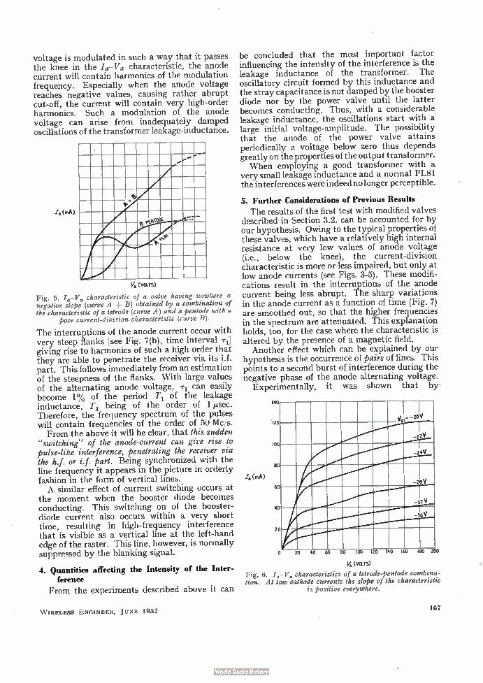
voltage is modulated in such a way that it passes the knee in the /a—Va characteristic, the anode current will contain harmonics of the modulation frequency. Especially when the anode voltage reaches negative values, causing rather abrupt cut-off, the current will contain very high-order harmonics. Such a modulation of the anode voltage can arise from inadequately damped oscillations of the transformer leakage-inductance.
(mA)
*O.
‘2,
?ogle
V1 (VOLTS)
Fig. 5. Id-V. characteristic of a valve having nowhere a negative slope (curve A + B) obtained by a combination of the characteristic of a tetrode (curve A) and a pentode with a
poor current-division characteristic (curve B).
The interruptions of the anode current occur with very steep flanks [see Fig. 7(b), time interval Ti] giving rise to harmonics of such a high order that they are able to penetrate the receiver via its i.f. part. This follows immediately from an estimation of the steepness of the flanks. With large values of the alternating anode voltage, Ti can easily become 1% of the period T, of the leakage inductance, T, being of the order of 1 µsec. Therefore, the frequency spectrum of the pulses will contain frequencies of the order of 50 Mc/s. From the above it will be clear, that this sudden
"switching" of the anode-current can give rise to pulse-like interference, penetrating the receiver via the h.f. or if. part. Being synchronized with the line frequency it appears in the picture in orderly fashion in the form of vertical lines. A similar effect of current switching occurs at
the moment when the booster diode becomes conducting. This switching on of the booster-diode current also occurs within a very short time, resulting in high-frequency interference that is visible as a vertical line at the left-hand edge of the raster. This line, however, is normally suppressed by the blanking signal.
4. Quantities affecting the Intensity of the Inter-ference
From the experiments described above it can
W IRELESS ENGINEER, JUNE 1952
be concluded that the most important factor influencing the intensity of the interference is the leakage inductance of the transformer. The oscillatory circuit formed by this inductance and the stray capacitance is not damped by the booster diode nor by the power valve until the latter becomes conducting. Thus, with a considerable leakage inductance, the oscillations start with a large initial voltage-amplitude. The possibility that the anode of the power valve attains periodically a voltage below zero thus depends greatly on the properties of the output transformer. When employing a good transformer with a
very small leakage inductance and a normal PL81 the interferences were indeed no longer perceptible.
5. Further Considerations of Previous Results The results of the first test with modified valves
described in Section 3.2. can be accounted for by our hypothesis. Owing to the typical properties of these valves, which have a relatively high internal resistance at very low values of anode voltage (i.e., below the knee), the current-division characteristic is more or less impaired, but only at low anode currents (see Figs. 3-5). These modifi-cations result in the interruptions of the anode current being less abrupt. The sharp variations in the anode current as a function of time (Fig. 7) are smoothed out, so that the higher frequencies in the spectrum are attenuated. This explanation holds, too, for the case where the characteristic is altered by the presence of a magnetic field. Another effect which can be explained by our
hypothesis is the occurrence of pairs of lines. This points to a second burst of interference during the negative phase of the anode alternating voltage.
Experimentally, it was shown that by
14
Ía (mA)
0 I
..' 20V
.22‘i
-24V
0
,0
I
-26V
-UV
K) -36V
0
>rt an an RA 1 00 120 140 160 180 2(
Va (VOLTS)
Fig. 6. /.- V. characteristics of a tetrode-pentode combina-tion. At low cathode currents the slope of the characteristic
is positive everywhere.
167
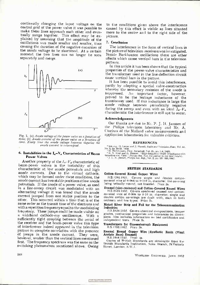
continually changing the input voltage on the control grid of the power valve it was possible to make these lines approach each other and even-tually merge together. This effect may be ex-plained by assuming that the amplitude of the oscillations was made smaller and smaller, thus causing the duration of the negative excursion of the anode voltage to be shortened. At a certain moment the two lines can no longer be seen separately and merge.
(b)
Fig. 7. (a) Anode voltage of the power valve as a function of time; (b) Anode current of the power valve as a function of time. Every time the anode voltage becomes negative the
anode current is interrupted.
6. Instabilities in the I„—Va Characteristics of Beam Power Valves
Another property of the /a— Va characteristic of beam-power valves is the instability of this characteristic at low anode potentials and high anode currents. Due to the virtual cathode, which may be formed under these conditions, the anode current has two stable positions at low anode potentials. If the anode of a power valve, as used in a line-sweep circuit was modulated with an alternating voltage it was found that the anode current jumped from one stable position to the other. This occurred within a time that is of the same order as the transit time of the electrons and with a repetition frequency equal to the modulating frequency. These jumps could be made visible on a wideband cathode-ray oscilloscope. With a sufficiently tight coupling between the aerial of the receiver and the beam-power valve this type of interference indeed appeared in the television picture in complete correlation with the presence of jumps in the anode current. They were, however, weaker than the vertical lines mentioned first. The frequency spectrum was the same as the switching phenomenon mentioned above. Owing
168
to the conditions given above the interference caused by this effect is visible as lines situated more to the centre and to the right side of the picture.
7. Conclusion
The interference in the form of vertical lines in the picture of television receivers was investigated. Beside Barkhausen oscillations there are other effects which cause vertical bars in the television pictures. •
In this article it has been shown that the typical properties of the power-valve characteristics and the transformer used in the line-deflection circuit cause vertical bars in the picture.
It has been possible to avoid this interference, partly by adopting a special valve-construction whereby the secondary emission of the anode is suppressed. An important factor, however, proved to be the leakage inductance of the transformer used. If this inductance is large the anode voltage becomes periodically negative during the sweep and even with an ideal /a—Va characteristic the interference is still apt to occur.
Acknowledgments
Our thanks are due to Mr. P. J. H. Janssen of the Philips television laboratory and Mr. A. Ciuciura of the Mullard valve measurements and application laboratories for valuable criticism.
REFERENCES
1 See, e.g., D. Lerner and J. Howell, Radio and Television News, Vol. 44, No. 3, 131). 50-51' 1950'
1 H. Barkhausen, Phys. Zeilschrift, Vol. 21, pp. 1-6, 1920. K. S. Knol and G. Diemen "High-frequency Diode Admittance with
Retarding d.c. Field," Philips Res. Rep. (to appear in the near future). J. L. If. Jonker, Philips Res. Rep., Vol. 2, pp. 331-339, 1947.
BRITISH STANDARDS
Cotton-Covered Round Copper Wires
13.S.1791:1951. Covers single and double cotton-covered wire of 0.006 to 0.192 in, diameter, the covering being helically wound, not braided. Price 2s.
Enamel (oleo-resinous) and Cotton-Covered Round Wires B.S.1815:1952. Covers combined enamel and cotton-
covered wire of 0.006 to 0.16 in. diameter; single and double cotton coverings are dealt with, each in both ordinary and fine types. Price 2s.
Nickel Silver Strip and Foil for the Telecommunication Industries
B.S.1824:1952. Covers chemical compositions, temper grades, mechanical properties and tolerances on dimen-sions. Also includes information on test certificates and independent tests. Price 2s.
Transformers for Cinematograph Equipment RS. 1793:1952. Price 2s.
Enamel Round Copper Wire [Synthetic Resin (Vinyl Acetate Base) Enamel]
13.S.1844:1952. Price 4s. Copies of British Standards are obtainable from the
British Standards Institution, Sales Branch, 24 Victoria Street, London, SW. 1.
W IRELESS ENGINEER, JUNE 1952

CORRESPONDENCE Letters to the Editor on technical subjects are always welcome. In publishing such communications the Editors do not necessarily endorse any technical or general statements which they may contain.
Cathode-Coupled Amplifier
SIR,—In your March 1952 issue, Mr. J. A. Lyddiard gives an interesting method of small-signal analysis of the very versatile cathode-coupled amplifier circuit. How-ever, for some applications his equivalent circuits are not sufficiently general, although it may be possible to extend his method to obtain more general results. An alternative and more general equivalent circuit which I have found useful is shown in Fig. 1. This enables the magnitudes of the currents in both anodes and in the cathode resistor to he calculated when either one or two signals are applied. The output impedance at either anode or the cathode can be found by calculating the impedance seen from terminals X, Y, or Z; the impedance obtained in this way is multi-plied by the same factor as the resistor joined to the terminals; e.g., the impedance seen from terminals Y, Y, is multiplied by (µ, ± 1).
am afraid that Mr. Lyddiard's treatment of harmonic distortion may be misleading. In particular, his state-ment that the harmonic distortion of the cathode-follower stage is usually negligible in practice, while probably quite justified in the case which he considers in detail, is not true in all practical cases. The cathode-follower, whose voltage ratio lies in the region of 0.5 to 0.7, can in fact produce distortion in amounts similar to, or even greater than, the earthed-grid stage. The even harmonics from the two stages are in opposite phase and some cancellation always takes place. The use of a high value of R/z, made possible by application of a positive bias to both grids, is advantageous in obtaining cancellation. A slight adjustment of the bias on one of the grids will usually permit almost complete cancellation of the even harmonics. In addition to improving linearity, the application of positive bias has other advantages: the anode currents of V1 and V, are made more nearly equal, thus avoiding the danger of exceeding the anode dissipation of V, mentioned by Mr. Lyddiard, the increased current in V, reduces 722 which, together with the increased value of RE, leads to a higher stage gain (see Fig. 1), and the greater d.c. feedback from the in-creased value of RE stabilizes the operating conditions of the valves, giving greater stability of gain.
(1-,z -4- I )ràf (P•1+1»12
(mi+ l)(µ2+ I)Rg Fig. 1.
An alternative method of calculating harmonic distor-tion, which is convenient and accurate, makes use of the input/output transfer characteristic of the stage. This can easily be calculated from the published valve curves as follows: the dynamic characteristic of V2 with its anode load is first found in the normal way; from this the values of V„ are found for a number of values of I and the following quantities calculated in turn for each value of 43; Vk, ki 4 2), Imp V21 (from the appropriate valve
curve), and then V,1. This permits the transfer character-istic (42/1/11) to be plotted. The bias for V1, if not already fixed, can now be chosen for minimum distortion and the harmonic distortion can then be calculated by any of the normal methods.
I. F. MACDIARMID. Dollis Hill,
London, N.W.2. 9th April, 1952.
Image Impedances of Active Linear Four-Terminal Networks
SIR,—The image impedance at the input and output terminals of a passive four-terminal network is a well-known and widely-used concept.' It is conveniently calculated or measured by using the formula:
7 112 — .311/Yii
II /2 o 2 tE2
(1)
Fig. 1.
where: Z1, is the image impedance at terminals 1 (see Fig. 1)
z„ is the input impedance at terminals 1 with terminals 2 open circuited.
yil is the input admittance at terminals 1 with terminals 2 short circuited.
Equation (1) still applies when the network is active, provided, of course, that the active elements are linear. This can be shown as follows, a knowledge of the appli-cation of simple matrix techniques2 to four-terminal networks being assumed;
In Fig. 1, [Ed _ [44c D./31[E1221 .. • • (2)
If the network is entirely passive, the restriction AD — BC = 1 is imposed on the matrix elements. No such restriction will be applied here.3
Let AD — BC -= .q
D — B
[ — — Then [E1221 — _ : [M .. .,
— — 3/ *1_
Now let the network be terminated at terminals 1 and 2 by external impedance Z, and Z 2 and let the imped-ances measured looking in to the corresponding terminals of the network under these conditions be Z' and Z. Then from (2)
from
AZ, B Z'
CZ, ± D •
(3) = DZ, B
Z" CZ, + A •
from (4) A 1 B z„ AB
Now let the external impedances be the image imped-ances; i.e., Z, = Z' = Zn, Z, = Z" = 7. 12
(3)
WIRELESS ENGINEER, JUNE 1952 169
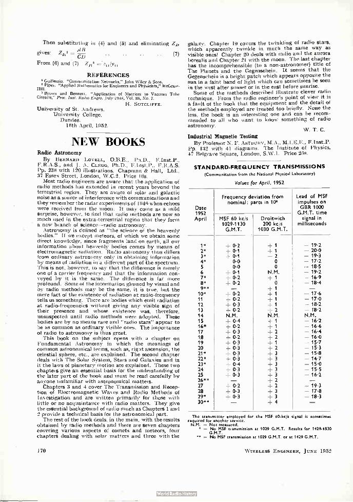
Then substituting in (4) and (5) and eliminating Z15 AB
gives: Zns = - • • (7) CD
From (6) and (7) Z112 = zidyn
REFERENCES ' Guillemin. "Communication Networks," John Wiley & Sons. Pipes. "Applied Mathematics for Engineers and Physicists," McGraw-
Brown and Bennett. "Application of Matrices to Vacuum Tube Circuits," Prot. Inst. Radio E'en, July 1948, Vol. 36, No. 7.
H. SUTCLIFFE. University of St. Andrews,
University College, Dundee.
18th April, 1952.
NEW BOOKS Radio Astronomy
By BERNARD LOVELL, 0.B.E., Ph.D., F.Inst.P., F.R.A.S., and J. A. CLEGG, Ph.D., F.Inst.P., F.R.A.S. Pp. 238 with 120 illustrations. Chapman & Hall, Ltd., 37 Essex Street, London, W.C.2. Price 16s. Most radio engineers are aware that the application of
radio methods has extended in recent years beyond the terrestrial region. They are aware of solar and galactic noise as a source of interference with communications and they remember the radar experiments of 1946 when echoes were received from the moon. It may come as a mild surprise, however, to find that radio methods are now so much used in the extra-terrestrial region that they form a new branch of science-radio astronomy. Astronomy is defined as "the science of the heavenly
bodies." If we except meteors, of which we obtain some direct knowledge, since fragments land on earth, all our information about heavenly bodies comes by means of electromagnetic radiation. Radio astronomy thus differs from ordinary astronomy only in obtaining information by means of radiation in a different part of the spectrum. This is not, however, to say that the difference is merely one of a carrier frequency and that the information con-veyed by it is the same. The difference is far more profound. Some of the information gleaned by visual and by radio methods may be the same, it is true, but the mere fact of the existence of radiation at radio-frequency tells us something. There are bodies which emit radiation at radio-frequencies without giving any visible sign of their presence and whose existence was, therefore, unsuspected until radio methods were adopted. These bodies are by no means rare and "radio stars" appear to be as common as ordinary visible ones. The importance of radio to astronomy is thus great.
This book on the subject opens with a chapter on Fundamental Astronomy in which the meanings of common astronomical terms, such as, right ascension, the celestial sphere, etc., are explained. The second chapter deals with The Solar System, Stars and Galaxies and in it the laws of planetary motion are explained. These two chapters give an essential basis for the understanding of the later part of the book and must be read carefully by anyone unfamiliar with astronomical matters.
Chapters 3 and 4 cover The Transmission and Recep-tion of Electromagnetic Waves and Radio Methods of Investigation and are written primarily for those with little or no acquaintance with radio matters. They give the essential background of radio much as Chapters 1 and 2 provide a technical basis for the astronomical part. The rest of the book deals, in the main, with the results
obtained by radio methods and there are seven chapters covering various aspects of comets and meteors, four chapters dealing with solar matters and three with the
170
galaxy. Chapter 19 covers the twinkling of radio stars, which apparently twinkle in much the same way as visible ones! Chapter 20 deals with radio and the aurora borealis and Chapter 21 with the moon. The last chapter has the incomprehensible (to a non-astronomer) title of The Planets and the Gegenschein. It seems that the Gegenschein is a bright patch which appears opposite the sun in a faint band of light which can sometimes be seen in the west after sunset or in the east before sunrise. Some of the methods described illustrate clever radio
technique. From the radio engineer's point of view it is a fault of the book that the equipment and the detail of the methods employed are treated too briefly. None the less, the book is an interesting one and can be recom-mended to all who want to know something of radio astronomy.
Industrial Magnetic Testing By Professor N. F. ASTBURY, M.A., M.I.E.E., F.Inst.P.
Pp. 132 with 41 diagrams. The Institute of Physics, 47 Belgrave Square, London, S.W.1. Price 25s.
W. T. C.
STANDARD-FREQUENCY TRANSMISSIONS (Communication from the National Physical Laboratory)
Values for April, 1952
Date 1952 April
Frequency deviation from nominal: parts in 108
MSF 60 kc/s 1029-1130 G.M.T.
Lead of MSF impulses on GBR 1000
G.M.T. time Droitwich signal in 200 kc/s J milliseconds
1030 G.M.T.
1* 4- 0.2 4- 1 - 19-2 2* + 0-1 1 - 20-0 3* 4- 0.1 2 - 19-3 4* 0.0 0 - 17.2 5 0.0 0 - 18-5 6 ± 0.1 N.M. - 19.2 7* + 0.2 1 - 16-9 8* + 0.2 0 - 18.4 9.* - 4 1 - 10* 4- 0.2 .4- 1 - 17-6 11 + 0.2 --: 1 - 17.0 12 4- 0.3 --' 1 - 18-2 13 + 0.2 -. 2 - 18.2 14 N.M. N.M. N.M. 15 + 0.4 1 - 16-2 16* + 0.2 -, 1 - 16.6 17 ± 0-3 4 2 - 16.4 18 4- 0.2 42 - 16-0 19 4- 0.3 41 20 + 0.3 4-2 - 15-3 21* ± 0-3 4 3 - 15-8 22* 4- 0.3 4 3 - 14-7 23* ± 0-4 _. 3 - 15.0 24 + 0.3 3 - 15.5 25 4- 0.3 4 3 - 16-2 26** - 4-2 _ 27 4- 0.2 4- 2 - 19.3 28 + 0.3 4-3 - 17.8 29* + 0.3 4- 3 - 18.3 30** - 4-4 -
The transmitter employed for the MSF 60-kg* signal is sometimes required for another service. N.M. = Not measured.
• = No MSF transmission at 1029 G.M.T. Results for 1429.1530 G.M.T.
•• = Na MSF transmission at 1029 G.M.T. or at 1429 G.M.T.
W IRELESS ENGINEER, JUNE 1952

Acoustics and Audio Frequencies
Aerials and Transmission Lines
Circuits and Circuit Elements
General Physics
Geophysical and Extraterrestrial Phenomena
Location and Aids to Navigation
Materials and Subsidiary Techniques
Mathematics
Measurements and Test Gear
Other Applications of Radio and Electronics
Propagation of Waves
Reception ..
Stations and Communication Systems
Subsidiary Apparatus
Television and Phototelegraphy
Transmission
Valves and Thermionics
Miscellaneous .
ABSTRACTS and REFERENCES Compiled by the Radio Research Organization of the Department of Scientific and Industrial
Research and published by arrangement with that Department.
The abstracts are classified in accordance with the Universal Decimal Classification. They are arranged within broad subject sections in the order of the U.D.C. numbers, except that notices of book reviews are placed at the ends of the sections. U.D.C. numbers marked with a dagger (t) must be regarded as provisional. The abbreviations of the titles of journals are taken from the World List of Scientific Periodicals. Titles that do not appear in this List are abbreviated in a style conforming to it.
PAGE expression for the field due to a point source is derived by A summation of multiple reflections of waves from a plane-
wave source. Its physical significance is discussed. 111
113
113
116
118
119
120
• 122
• 122
• 124
126
• 127
127
129
• 129
131
• 131
• 132
ACOUSTICS AND AUDIO FREQUENCIES
016 : 534 1487 References to Contemporary Papers on Acoustics.—
R. T. Beyer. (J. acoust. Soc. Amer., Nov. 1951, Vol. 23, No. 6, pp. 724-730.) Continuation of 293 of February.
534.121.2.001.362 1488 Transformer Analogs of Diaphragms. B. B. Bauer.
(J. acoust. Soc. Amer., Nov. 1951, Vol. 23, No. 6, pp. 680-683.) The action of a diaphragm is shown to be analogous to that of a system of ideal transformers, each corresponding to a particular area of the diaphragm. Equivalents for various types of diaphragm are described.
534.152 1489 Demonstration of Standing Waves in the Free Acoustic
Field, and a Simple Receiver for Short Acoustic Waves.— R. \V. Pohl. (Naturwissenschaften, Nov. 1951, Vol. 38, No. 21, pp. 486-490.) Two methods of recording a standing-wave pattern are described. A shadow picture is obtained of (a) the disturbance of a liquid surface (water or petrol) over which the sound wave is projected, or (b) the turbidity in a soap film arranged obliquely in the sound field. Application of the first method in acoustic measurements is illustrated.
534.21-14 1490 Normal-Mode Propagation in Three-Layered Liquid
Half-Space by Ray Theory. —C. B. Officer, Jr. (Geophys., April 1951, Vol. 16, No. 2, pp. 207-212.) The integral
W IRELESS ENGINEER, JUNE 1952
534.21-14 621.31001.362 1491 The Formal Connection between the Corpuscular
Theory of Sound Propagation in Liquids and Problems of Electrical Engineering, particularly the Theory of Quadripoles.—K. Altenburg. (Frequenz, Oct. 1951, Vol 5, No. 10, pp. 285-289.)
534.213.4 1492 Propagation of Sound in a Duct with Constrictions.— . Ingárd & 1). Pridmore-Brown. (J. acoust. Soc.
Amer., Nov. 1951, Vol. 23, No. 6, pp. 689-694.) Iris partitions are uniformly distributed along the duct. Attenuation is determined as a function of frequency for ducts with hard and with absorptive walls, charts being given for hard-wall ducts. By proper choice of wall absorption and iris dimensions and spacing, a wide attenuation band can be obtained. Measured values of attenuation are in good agreement with theory.
534.231 : 534.26 1498 On the Relation between the Sound Fields Radiated and
Diffracted by Plane Obstacles.—F. M. Wiener. (J. acoust. Soc. Amer., Nov. 1951, Vol. 23, No. 6, pp. 697-700.) The analogy between acoustic diffraction and radiation problems is discussed; a very simple relation exists between a plane rigid scatterer exposed to a per-pendicularly incident plane wave and a plane piston radiator. The radiated field is proportional to the scattered field. A similar relation exists between the radiation impedance and the force per unit pressure exerted on the scatterer.
534.232: 538.652 1494 Magnetostriction Transducer Measurements.—H. J.
Round. (Wireless Ene, April 1952, Vol. 29, No. 343, pp. 101-105.) Description of a simplified method, based on equivalent circuits, for determining the constants of a magnetostriction oscillator.
534.24: 534.213.4 1496 An Analysis of the Effect of the Discontinuity in a
Bifurcated Circular Guide upon Plane Longitudinal Waves. --L. L. Bailin. (Boor. Stand. J. Res., Oct. 1951, Vol. 47, No. 4, pp. 315-335.) A theoretical treatment of the scattering of sound by a semi-infinite tube of small diameter inserted axially into a larger tube of infinite length. The theory is rigorous and explicit provided the waves incident at the discontinuity are restricted to the lowest mode of propagation. The problem is a particular case of the general problem of the effects of obstacles on the propagation of acoustic or em. waves in guides.
534.321.9.047: 621.431.75 1496 Ultrasonic Spectra emitted by Aircraft Propulsion
Mechanisms, and their Physiological Effects. -1'. Grognot. (Ann. Té/écommun., Nov. 1951, Vol. 6, No. 11, pp. 341-344.)
A.111
534.373-13 1497 The Absorption of Sonic and Ultrasonic Waves in
Gases.-M. Dubois. ( J. Phys. Radium, Nov. 1951, Vol. 12, No. 9, pp. 876-884.) Theoretical and experi-mental investigation of the general problem of the attenuation of a plane wave due to the physical properties of the medium and to variations of pressure, temperature and molecular energy caused by the passage of the wave. 80 references.
534.422: 534.321.9.043/.047 1498 A New Improved Type of Ultrasonic Siren.-L.
Pimonow. ( Ann. Télécommun., Nov. 1951, Vol. 6, No. 11, pp. 337-341.) An earlier design (1822 of 1951) has been improved by truncating the rotor, increasing its speed, and introducing a reflecting surface.
534.522 1499 Theory of Optical Method of Sound Analysis.-J •
Picht. ( A mt. Phys., Lpz., 1949, Vol. 5, Nos. 3/5, pp. 117-132 & 1951, Vol. 9, No. 8, pp. 381-400.) Development of the theory and derivation of formulae applicable to the method described by Schouten (1549 of 1939, 1062 and 1452 of 1940), and modification of the method for combinations of acoustic frequencies with arbitrary phase relations.
534.75 1500 Compression Properties of the Ear. -H. Mol. ( Tijdschr.
ned. Radiogenoot., Nov. 1951, Vol. 16, No. 6, pp. 277-291.) Analysis of the compressive action of the ossicle chain. The large dynamic range of the human ear is ascribed to this.
534.79: 534.839 1501 On the Measurement of the Loudness of White Noise.-
I. Pollack. (J. acoust. Soc. Amer., Nov. 1951, Vol. 23, No. 6, pp. 654-657.) A scale of loudness for white noise was obtained by independent subjective methods which show consistency among themselves. It is suggested that this scale forms a better measure for complex sounds than a pure-tone scale.
534.79: 534.839 1502 On the Threshold and Loudness of Repeated Bursts of
Noise.-1. Pollack. ( J. acoust. Soc. Amer., Nov. 1951, Vol. 23, No. 6, pp. 646-650.) Full paper. Summary noted in 543 of 1951.
534.79: 534.839 1503 Sensitivity to Differences in Intensity between Repeated
Bursts of Noise. - -1 . I 'ollac k. (J. acoust. Soc. Amer., Nov. 1951, Vol. 23, No. 6, pp. 650-653.)
534.833.4-13 /- 14 1504 Absorption of Sound in Fluids.-J. J. Markham, R. T.
Beyer & R. B. Lindsay. (Rev. mod. Phys., Oct. 1951, Vol. 23, No. 4, pp. 353-411.) A critical review and unified presentation of the fundamental theories of absorption of sound in gases and liquids, together with an outline of experimental techniques. A summary of the reliable experimental results (mainly at frequencies between 1 Mc/s and 100 Mc/s) is included and these are interpreted in terms of the theoretical concepts. 225 references.
534.844.1 : 621.396.615.11 1505 Equipment for Acoustic Measurements: Part 3-
Acoustic Pulse Measurements.-Mayo, Beadle & Wharton. (See 1681.)
534.848.4 1506 Speech Reinforcement in St. Paul's Cathedral.
P. H. Parkin & J. H. Taylor. (Wireless World, Feb. & March 1952, Vol. 58, Nos. 2 & 3, pp. 54-57 & 109-111.)
A.112
Discussion and illustrated description of the system recommended, showing results of acoustic tests. The dome area is served by two 11-ft vertical arrays of loud-speakers mounted beside the pulpit and the lectern; they comprise eleven 10-in, and nine 3h-in. loudspeakers covering the restricted range of 250-4 000 c/s with crossover at 1 000 c/s. Six 6-ft loudspeaker arrays mounted on piers in the nave are fed through a time-delay mechanism consisting of a turntable carrying an 11-in, disk of plastic magnetic material with recording, playback and erasing heads, an ultrasonic erasing head being provided to guard against failure of the magnetic erasing equipment.
534.85: 681.84 1507 New Developments in the Gramophone World.- L.
Mons. (Philips tech. Rev., Nov. 1951, Vol. 13, No. 5, pp. 134-144.) Properties required of record disks and reproducing apparatus for long playing are discussed; a description is given of Philips apparatus which gives a playing time of 22h min for a microgroove 12-in, record and which also takes ordinary records.
534.861.1 1508 Orchestral Studio Design. Recent Modifications to the
B.B.C. Maida Vale Studio.-T. Somerville & H. R. Humphreys. (Wireless World, April 1952, Vol. 58, No. 4, pp. 128-131.) The acoustic properties of this studio in its original state were characterized by excessive reverber-ation time at low frequencies and extreme deadness at high frequencies. Architectural modifications which have led to very large improvements are described; these in-clude the application to the walls of box-type 'membrane absorbers' resonant at various low frequencies, and the rebuilding of the orchestra platform.
621.395.61/.62: 621.395.625.3 1509 Investigation of Transducers by Repeated and Retro-
grade Re-recording.-W. Meyer-Eppler. (Eernmeldetech. Z., Nov. 1951, Vol. 4, No. 11, pp. 507-512.) Analysis showing how slight linear distortion occurring in an electroacoustic transducing system due to transit-time effects may be determined by repeated re-recording. By reversing the direction of motion of the magnetic tape, phase distortion can be totally compensated. Application of the technique in acoustic tests of rooms is outlined.
621.395.623.7 1510 Direct Radiator Loudspeaker Enclosures.-H. F.
Olson. (Audio Engng, Nov. 1951, Vol. 35, No. 11, pp. 34-38 . . 64.) A comprehensive analysis of the effects of various shapes of cabinet shows_ that for optimum performance the cabinet front must have no sharp edges.
621.395.625.3 1511 Magnetic Sound-Recording.-F. Duchâteau. (HF,
Brussels, 1951, No. 11, pp. 303-312.) Discussion of the main technical difficulties involved and of the means devised to overcome them.
621.396.645.029.3 1512 An Ultra-Linear Ampliffer.--D. Hafler & H. I. Keroes.
(Audio Engng, Nov. 1951, Vol. 35, No. 11, pp. 15-17.) The screen-grid of a tetrode is energized with d.c. from a low-impedance source through a special winding on an Acrosound TO-300 output transformer, in which the effects of the anode and screen-grid currents are combined. The screen-grid load impedance must be about 18.5% of the anode load impedance. A circuit incorporating this output stage is shown diagrammatically, with component values. The power output of over 20 W is undistorted within 1 db from 20 to 20 000 c/s, intermodulation being less than 2%.
W IRELESS ENGINEER, JUNE 1952

AERIALS AND TRANSMISSION LINES
621.392.26 1513 The Susceptance of a Thin Iris in Circular Wave Guide
with the TMoi Mode Incident.-K. L. Dunning & R. G. Fellers. ( J. app!. Phys., Nov. 1951, Vol. 22, No. 11, pp. 1316-1320.) "Certain wave-guide boundaty value pro-blems can be formulated in terms of lumped-constant circuits and distributed-constant transmission lines. Equivalent circuit voltages and currents can be introduced as measures of the transverse electric and magnetic fields. Making use of these concepts and Schwinger's integral equation method, the susceptance of a thin circular iris in circular cylindrical wave guide with the TM., mode incident is discussed and calculated. Results are com-pared with experimental data."
621.392.26.012.3 1514 Tea Waves in Rectangular Waveguides.--( Radio &
Televis. News, Radio-Electronic Engng Section, Sept. 1951, Vol. 46, No. 3, p. 32.) Nomogram for determination of cut-off frequency from dimensions of guide.
621.392.43.012.3 1515 Matching-Stub Calculations.-S. Yamasita. (Radio &
Televis. News, Radio-Electronic Engng Section, Aug. 1951, Vol. 46, No. 2, pp. 32, 31.) A nomogram for deter-mining the position and length of matching stubs on Lecher-wire lines.
621.396.67 1516 General Theory of Symmetric Biconical Antennas.-
S. A. Schelkunoff. (J. app!. Phys., Nov. 1951, Vol. 22, No. 11, pp. 1330-1332.) The input admittance of a biconical aerial of arbitrary angle is expressed as the limit of a certain sequence of functions. The first term of this sequence approaches the exact expressions for input admittance as the cone angle approaches either zero or 90'; hence it probably constitutes a good first approxi-mation for all angles.
621.396.67 : 621.397.6 1517 Antennas for U.H.F.-E. C. Johnson & J. D. Callaghan.
(FM-TV, Nov. 1951, Vol. 11, No. 11, pp. 16-18. . 56.) illustrated descriptions of different types of aerial for television reception, showing their field patterns and gain characteristics.
621.396.677 1518 The Necessary Number of Elements in a Directional
Ring Aerial.-H. L. Knudsen. ( J. appl. Phys., Nov. 1951, Vol. 22, No. 11, pp. 1299-1306.) Discussion based on the theories 6f Page (1862 of 1948 and 308 of 1949) and Stenzel (1929 Abstracts, p. 450). An expression is derived for the characteristic of an array with a finite number of elements. This expression shows that no uniform improvement of the approximation of the array characteristic to the ideal is obtained by increasing the number of elements, but in this respect odd numbers of elements are better than even numbers.
621.396.677.029.6 1519 Measurement of Radiation of U.S.W . Aerials.--
J. Delcambe. (HF, Brussels, 1951, Nos. 11 & 12, pp. 293-302 & 327-335.) If the aerial aperture field distribu-tion is very nearly plane and equiphase, application of the Kottler formulae previously noted [2109 of 1951 (Divoire & Delcambe)] gives numerical values for the directive properties of waveguide, horn and microwave-lens aerials with an accuracy sufficient to meet practical requirements. Gain can be estimated to within 7%. The measurement methods applied and precautions taken are detailed. An appendix describes a microwave bolo-meter-type wattmeter developed for the purpose.
W IRELESS ENGINEER, JUNE 1952
621.396.677.5t : 621.318.424 1520 Ferromagnetic Loop Antennas.-W. J. Polydoroff.
(Radio & Televis. News, Radio-Electronic Engng Section, Nov. 1951, Vol. 46, No. 5, pp. 11-13. . 24.) From results on loops with ferrite cores it is concluded that, in their design, (a) a balance must be struck between an acceptable value of Q and maximum effective permeability, a Q of 125-150 being considered most suitable, (b) cylindrical cores of length/diameter ratio > 10 give greater effective height; (c) the winding should cover 80% of the core length; (d) the wire, if insulated by vinylite or double cotton covering, may be wound directly o the core; (e) the core should be in the shape of hollow tubing. Various applications where reduction in aerial ize is important are suggested. See also 2485 of 1946 (burgess).
621.396.677.6.029.6 : 621.396.931 ' 9313 1521 Rotating H-Type Adcock Direction-Finders for Metre
and Decimetre Wavelengths. -H. G. Hopkins & F. Homer. (Proc. Instn elect. Engrs, 'art 111, March 1952, Vol. 99, No. 58, pp. 96-97.) Long summary of 598 of March.
CIRCUITS AND CIRCUIT ELEMENTS
621-52: 621.396.611.3 1522 Applications of Electrical Methods of Differentiation to
Control Problems.-Rateau. (See 1688.)
621.3.015.7 1523 A Pulse Mixing Unit.-R. R. Rathbone & R. L. Best.
(Radio & Televis. News, Radio-Electronic Engng Section, Sept. 1951, Vol. 46, No. 3, pp. 10-11, 27.) The unit described accepts pulses from up to eight external lines, mixes them at the input, and delivers them with a delay of 0.08 p.s as a single output train. Positive pulses of random form with amplitudes from 6 to 60 V are con-verted to pulses of half-sine-wave form, of duration 0. I ps, with amplitudes varying by not more than 5%.
621.3.015.7 1524 The Pulse Standardizer.-R. R. Rathbone. (Radio
& Televis. News, Radio-Electronic Engng Section, Nov. 1951, Vol. 46, No. 5, pp. 6-7, 31.) Description of equip-ment which accepts pulses of random amplitudes (>6 V), with repetition rate up to 3 x 10⁸/sec, and converts them to a set of pulses of uniform amplitude (up to 37 V) and with the same recurrence frequency. Pulses with repetition rates up to 5 x 10⁸/sec can be accepted if a 10% reduction of the maximum output-pulse voltage can be tolerated.
621.3.015.7 : 621.396.6 1525 Pulse Circuits for the Millimicrosecond Range. -F. H.
Wells. (J. Brit. Instn Radio Engrs, Nov. 1951, Vol. 11, No. 11, pp. 491-503.) The circuits described include pulse-shaping circuits, pulse generators, amplifiers, scalers, and recording oscilloscopes. Applications to high-speed coincidence measurements, millimicrosecond time-interval measurements and fast counting are described.
621.3.015.7 : 621.396.619.16 1526 Conversion of Rectangular Pulses of Given Width and
Variable Height into Rectangular Pulses of Given Height and Variable Width.-W. Vogt. (Funk u. Ton, Nov. 1951, Vol. 5, No. 11, pp. 578-584.) In the circuit de-scribed, a.m. pulses charge a capacitor in the positively biased grid circuit of a switching valve which is conduc-tive during the capacitor discharge. The discharge time is a function of the charging voltage. The nonlinearity of this relation is studied. Methods of improving the linearity are indicated.
A.113
621.314.222.012.3 1527 Charts for the Calculation of Mains Transformers.
-G. Pavel. (Funk u. Ton, Nov. 1951, Vol. 5, No. 11, pp. 561-577.) Design parameters are discussed. The charts relate core size, number of turns, wire diameter, and resistance of primary and secondary windings of mains transformers for powers up to 150 W. Special charts are provided for E- and M-shaped laminated cores of standard materials.
621.314.3t : 621.314.5 1528 Magnetic Modulators.-E. P. Felch, V. E. Legg & F. G.
Merrill. (Electronics, Feb. 1952, Vol. 25, No. 2, pp. 113-117.)
621.316.8 1529 The Problem of a Non-ohmic Resistor in Series with an
Impedance.-E. B. Moullin. (Proc. [min elect. Engrs, Part I, Nov. 1951, Vol. 98, No. 114, pp. 344-346.) Discussion on 2657 of 1951.
621.316.8.029.5 1580 Resistors at Radio Frequency.-T. J. F. Pavlasek &
F. S. Howes. (Wireless Engr, Feb. 1952, Vol. 29, No. 341, pp. 31-36.) The r.f. resistance and distributed capa-citance of resistors of the metallized-filament type enclosed in insulating sleeves were investigated at frequencies from 0.5 to 40 Mc/s. Curves of Re/Rd., Z/Rd. and 4, are plotted against f. Rd., Re and R. being respectively the r.f. and d.c. resistances, f the frequency and e the phase angle. A comparison is made with the theoretical values obtained by considering the resistor as a transmission line having distributed resistance and capacitance.
621.318.572 : 621.385.2 1531 B.F. Bursts actuate Gas-Tube Switch.-Geisler. (See
1786.)
621.318.572+681.142] : 621.385.5.032.212 1532 The Single-Pulse Dekatron.-Acton. (See 1787.)
621.385.2 : 546.289] + 621.314.7 1538 Germanium Crystal Valves.-Bettridge. (See 1785.)
621.392.012 : 517.63 1534 Block-Diagram Network Transformation. - T. D.
Graybeal. (Elect. Engng, N.Y., Nov. 1951, Vol. 70, No. 11, pp. 985-990.) Essentially full text of 1951 A.I.E.E. Pacific General Meeting paper. A convenient method particularly applicable to the analysis and syn-thesis of servo systems. The Laplace transform equations of the system are expressed in the form of a block dia-gram. By methods similar to the star-delta transforma-tion, complicated systems may be reduced to one of a few simple forms.
621.392.5 1585 A Network Theorem.-E. E. Zepler. (Wireless Engr,
Feb. 1952, Vol. 29, No. 341, pp. 44-45.) To find the effect of connecting an impedance Z across two points of a network, the impedance may be replaced by one in parallel with the generator. A simple formula is given from which the value of this parallel impedance can be found.
621.392.5 1538 Minimum Phase Networks.- J . A. Tanner. (Electronic
Engng, Nov. 1951, Vol. 23, No. 285, pp. 418-423.) A 'minimum phase network' is a feedback network having a minimum value of phase lag at every frequency while satisfying a specified gain/frequency characteristic. The properties of such networks are summarized in relation to their use in servo systems.
A.114
621.392.5 : 621.396.621.53 1587 The Parallel-T Network as a Linear Mixer.-J. S.
Nisbet. (Electronic Engng, Nov. 1951, Vol. 23, No. 286, pp. 432-433.) Two oscillations are mixed by applying them across opposite sides of a parallel-T network and taking the output from one of the mid-shunt arms. The circuit operation is analysed. Coupling between the two oscillators is avoided over a small frequency band.
621.392.5 : 681.142 1538 Linear Networks with Time-Varying Lumped Para-
meters.-J. Brodin. (C. R. Acad. Sci., Paris, 12th Nov. 1951, Vol. 233, No. 20, pp. 1168-1170.) The equations of a system are expressed by means of an integration operator. The method is applied to the calculation of the pass band of an electro-analogue multiplier with a time-varying network.
621.392.5.029.3 : 621.3.012.3 1589 The Prediction of Audio-Frequency Response: No. 1-
Circuits with Single Reactance Element.-N. H. Crowhurst. (Electronic Engng, Nov. 1951, Vol. 23, No. 285, pp. 440-443.) The first of a series of data sheets; applicability is not restricted to the a.f. range.
621.392.5.029.3 : 621.3.012.3 1540 The Prediction of Audio-Frequency Response: No. 2 -
Circuits with Two Reactance Elements.-N. H. Crowhurst. (Electronic Engng, Dec. 1951-Feb. 1952, Vols. 23-24, Nos. 286-288, pp. 483-489, 33-38 & 82-86.) Formulae and charts are presented applicable to circuits reducible to a combination of series inductance and shunt capacitance. or series capacitance and shunt inductance, together with resistances.
621.392.52 1541 Tchebyshev Filters and Amplifier Networks.-V.
Belevitch. (Wireless Engr, April 1952, Vol. 29, No. 343, pp. 106-110.) Darlington's method of filter synthesis (1361 of 1940) is applied to the design of simple low-pass filters composed of alternate series coils and shunt capacitors. Resistive termination of both ends is con-sidered and also the case where one end is on open circuit. When filters of this type are used as amplifier input or output networks, the prescribed valve of the terminal shunt capacitance imposes a physical limitation on the gain-bandwidth product of the stage; this limitation has been studied by Bode (583 of 1946), but additional precision results from the present analysis. More general filters with one open-circuit termination are mentioned and a new method of design is outlined. The results can be extended to other than low-pass fillers by means of frequency transformations.
621.392.52 1542 RC Networks as Filters.-H. Pieplow. (Arch. tech.
Messen, Oct. & Dec. 1951, Nos. 189 & 191, pp. T117-T118 & T141-T142.) Common types are analysed and tabulated according to their filter properties. Means of improving the filtering action are considered, and it is found possible, by the addition of amplitude-stabilizing devices, to reduce distortion at the output of an RC oscillator to about 0.1-0.2%. Negative feedback in con-junction with specially designed networks enables ampli-fiers to be constructed with almost any desired filter properties and stability of operation.
621.392.52 1543 Ladder Filters without Attenuation Fluctuations in the
Pass Band (Power-Law Filters).-G. Bosse. (Frequenz, Oct. 1951, Vol. 5, No. 10, pp. 279-284.) An analytical treatment deriving design formulae for such filters, the overall group delay of which is expressed by a power
W IRELESS ENGINEER, JUNE 1952
series. Attenuations, phase delays and transfer functions are shown for symmetrical low-pass filters with 1, 2 and 3 T-type units.
621.392.52 1544 Composite Ladder Filters, Second-Order Image Im-
pedances.-R. O. Rowlands. (Wireless Engr, Feb. 1952, Vol. 29, No. 341, pp. 50-55.) Design formulae are derived for filters comprising up to three half-sections and having equal or inverse impedance functions of the second order. Their performance is equal to that of the conventional m-derived type, but fewer components are required. Other filters are described having a second-order impedance function at only one pair of terminals.
621.392.52 1545 The Numerical Calculation of Filter Circuits with
Generalized Parameters, using Modern Theory with Special Attention to Cauer's Work.-V. Fetzer. (Arch. eleht. übertragung, Nov. 1951, Vol. 5, No. 11, pp. 499-508.) Cauer applied the operating-parameter theory to the calculation of Tchebycheff-type filters; in the present paper this theory is applied to filters having infinite-attenuation points anywhere in the attenuation band while conforming to Tchebycheff type within the pass band. Explicit formulae are derived for the coefficients of the characteristic function, which is developed as a polynomial; the zero-attenuation points are found by solving the corresponding higher-order equation. The relations between Cauer's Q functions and the charac-teristic function are shown for both symmetrical and 'antimetrical' filters. Darlington's formulae (1361 of 1940) for the basic low-pass circuit are used to calculate the circuit elements from the no-load impedance.
621.392.52 : 518.4 1546 New Graphical Methods for Analysis and Design.-W.
Saraga & L. Fosgate. (Wireless Engr, March 1952, Vol. 29, No. 342, pp. 68-79.) Methods are developed for transforming a given performance characteristic into a straight line or a set of straight lines. The method is demonstrated by applying it to the analysis and design of image-parameter and insertion-parameter filters.
621.392.6 1547 Synthesis of Passive Electrical Networks with n Pairs
of Terminals and Prescribed Scattering Matrix [matrice de répartition].-V. Belevitch. (Ann. Télécommun., Nov. 1951, Vol. 6, No. 11, pp. 302-312.) Full paper referred to in 2128 of 1951. The term 'matrice de répartition' is used to denote the matrix representing the distribution of power between given terminating impedances.
621.395.661.1 1548 Repeater Coil with Divided Secondary Winding and
Single Stray-Resonance Peak.-0. Hiner. ( Frequenz, Oct. 1951, Vol. 5, No. 10, pp. 265-272.) From an equivalent circuit the conditions are determined under which only one resonance peak occurs in the response characteristic. In this case the pass band can be about 40% wider than that obtainable when the response characteristic has two peaks. See also 1088 of 1951 (Schmitt & Schrag).
621.396.6-181.4 1549 Miniaturization-Crux of Contemporary Product De-
sign.-W. H. Hannahs & B. S. Ellefsen. (Elect. Mfg, N.Y., June 1950, Vol. 45, No. 6, pp. 86-91 . . 200.) Review of techniques applied to circuit components and subassemblies.
621.396.611.4 1550 Some Results from the Theory of Coupled Electro-
magnetic Cavity Resonators.-E. Ledinegg & P. Urban.
W IRELESS ENGINEER, JUNE 1952
(Acta phys. austriaca, Dec. 1950, Vol. 4, Nos. 2/3, pp. 180-196.) Based on the theory developed previously (1115 of 1951), the coupling frequencies are calculated for some systems of particular interest, e.g. cylindrical cavities coupled at the flat ends by windows or coaxial-line sections. Comparison is made with experimental results.
621.396.615 1551 Blocking-Oscillator Amplitude Control.-(Electronic
Engng, Nov. 1951, Vol. 23, No. 285, p. 439.) Circuits are described in which the amplitude of the oscillator output is adjusted by varying the bias applied to the suppressor grid.
621.396.615 1558 Distortion in Beat-Frequency Sources.-C. G. Mayo.
(Wireless Engr, April 1952, Vol. 29, No. 343, pp. 92-94.) At higher beat frequencies than that at which the two oscillators of a beat-frequency source lock, there is dis-tortion of the beat-frequency waveform. Analysis shows that at any frequency co/Ir the second-harmonic dis-tortion is cuo/2ta, where w0/27r is the highest beat frequency at which locking occurs.
621.396.615.077.2/.3 1558 An Amplidyne Phase Shift Oscillator. -J. C. West.
(J. sci. Instrum., Nov. 1951, Vol. 28, No. 11, pp. 336-339.) An oscillator is described capable of developing a peak current of 3 A in a 17-0 load over the frequency range 0-06-18 c/s. The amplidyne with its associated electronic amplifier has a local feedback loop to reduce the effects of saturation and hysteresis in the magnetic circuit. Application is to the determination of the frequency response of servomechanisms.
621.396.615.17 1554 Three-Valve Pulse Generator with Fixed Repetition
Rate.-F. A. Benson & G. V. G. Lusher. (Wireless Engr, April 1952, Vol. 29, No. 343, pp. 90-91.) A development of the 2-valve generator previously described (1244 of May), producing short positive pulses of amplitude about 50 V, using a square-wave input from either a multi-vibrator or a clipping circuit.
621.396.615.17 : 621.314.7 1555 Transistors as Multivibrators.-I. Queen. (Radio-
Electronics, Sept. 1951, Vol. 22, No. 12, pp. 92, 94.) A multivibrator using two transistors, and a flip-flop circuit using a single transistor, are described. Both are triggered by a differentiated square-wave voltage.
621.396.615.17.012.3 1556 A Nomogram for Idultivibrator Design.-W. R.
Luckett. (Electronic Engng, Nov. 1951, Vol. 23, No. 285, p. 448.)
621.396.615.18 1557 Decade Multivibrator Design. Method of Stabilizing
Frequency Division from a Crystal Drive.-J. E. Attew. (Wireless World, March 1952, Vol. 58, No. 3, pp. 114-116.) Spasmodic momentary jumping to the next lower ratio of division often occurs in a crystal-driven decade multi-vibrator, even though synchronized for even division. This is prevented by applying a pulse of opposite polarity just before the true synchronizing pulse. A complete circuit diagram of a stable frequency-division system embodying this principle is shown. Setting-up procedure is outlined.
621.396.645 1558 A New Push-Pull Amplifier Circuit.-A. P. G. Peterson.
(Gen. Radio Exp., Oct. 1951, Vol. 26, No. 5, pp. 1-7.)
A.115
Power-amplifier applications of the circuit described in 1250 of May are considered.
621.396.645 1559 Cathode-Coupled Amplifier.- J. A. Lyddiard. (Wireless
Engr, March 1952, Vol. 29, No. 342, pp. 63-67.) Analysis is presented in which the cathode-coupled amplifier is treated as a cathode follower driving an earthed-grid voltage amplifier. The method is simple, and leads to a straightforward design procedure.
821.396.645 : 621.3.015.3 1560 Overvoltage Effect in R.F. Power Amplifiers.-E.
Rizzoni. (Alta Frequenza, Oct. 1951, Vol. 20, No. 5, pp. 200-209.) The effect of overvoltage at the terminals of the anode oscillatory circuit of a r.f. power amplifier, due to detuning of the anode circuit, is discussed, and a method of calculating it as a function of load admittance and amount of detuning is described. Calculations and graphs are presented for the FIVRE beam tetrode Type 4-0500 and the R.C.A. triode Type 893 A-R.
821.396.645 : 621.315.612.4 1561 Dielectric Amplifier Fundamentals.-A. M. Vincent.
(Electronics, Dec. 1951, Vol. 24, No. 12, pp. 84-88.) The input voltage is applied across a capacitor with ferro-electric dielectric, whose reactance is thereby varied; the capacitor is in circuit with an a.c. power source and load, and amplified power variations appear across the latter. The impedance of the circuit is relatively high. Practical forms of the amplifier are described, and its operation is compared with that of magnetic and valve amplifiers; at present the frequency range appears to have an upper limit at about 10 Mc/s. Numerous applications are indicated.
821.396.645 : 621.392.52 1562 Broad-Banding by Stagger Tuning.-R. C. Wittenberg.
(Electronics, Feb. 1952, Vol. 25, No. 2, pp. 118-121.) Simplified methods are presented for design calculations of multi-circuit stagger-tuned i.f, amplifiers to have either Butterworth or Tchebycheff type of response. Tables and charts are given and their use illustrated. Circuits with bandwidths up to twice the centre frequency are designed using noncritical values of components.
621.396.645.37 1563 Highly-Selective Amplification at Low Frequencies.-
F. J. Hyde. (Wireless Engr, April 1952, Vol. 29, No. 343, pp. 85-90.) Analysis is presented of the unbalanced twin-T RC filter with series arms R and C and shunt arms aR/2 and 2C. The locus of the transmission vector, for 0.5<a<1.0 is approximately circular and the phase angle varies continuously from 0 to 2ir radians. A single-stage amplifier with series feedback through a balanced twin-T filter (a = 1) has a Q value of A/4 when A, the loaded stage gain without feedback, is large. Unbalancing of the filter by making a < 1, gives improved selectivity, and a working Q of 20 can be readily obtained. Experi-mental results are given for filters with resonance fre-quencies of about 0.25, 0.5, and 360 c/s.
621.396.645.37 1564 Dual Circuit of a Feedback Amplifier.-D. A. lit•11
(Wireless Engr, Feb. 1952, Vol. 29, No. 341, pp. 40-43.) The dual circuit of a single-stage amplifier is first obtained. The duals of (a) a single-stage amplifier with a voltage-feedback branch, (b) a combination of two amplifiers with local feedback round each and additional feedback over both stages, are then derived.
621.396.645.37.012.8 1565 Equivalent Circuits to Simplify Feedback Design.-
R. S. Burwen. ( .4 udio Engng, Oct. 1951, Vol. 35, No. 10,
A.116
pp. 11-12 . . 45.) Equivalent circuits are used in analysis of the general feedback amplifier. Voltage and current feedback are considered separately. The effect of a small amount of feedback on power amplifiers is studied; a 16-0 loudspeaker winding in the cathode circuit is sufficient to provide 6 db feedback in a single-pentode output stage. Application of equivalent circuits in the design of a preamplifier circuit with a prescribed response curve is described.
621.396.645.371.011.1 1566 Expressions for the Reduction of Distortion and Output
Impedance in Terms of db of Feedback.-W. J. Kessler & S. E. Smith. ( Audio Engng, Oct. 1951, Vol. 35, No. 10, p. 13.) The feedback factor is eliminated from the formulae usually applied, in order to obtain formulae expressed in terms of parameters easily measured.
621.3.015.7 1567 Pulse Techniques. [Book Reviem]-S. Moskowitz &
J. Racker. Publishers: Prentice-Hall, New York, 1951, 300 pp., $5.00. (J. Franklin Inst., Aug. 1951, Vol. 252, No. 2, p. 203.) "The book is apparently intended as a text for a brief undergraduate course in the pulse aspects of electronics."
621.392 1568 Circuits in Electrical Engineering. [Book Review]-
C. L. Vail. Publishers: Prentice-Hall, New York, 1950, 560 pp., $5.75. (J. appl. Phys., Nov. 1951, Vol. 22, No. 11, p. 1391.) "Primarily intended ás a textbook [of circuit analysis] and not as a reference work."
621.396.6 + 621.385 1560 Introduction to Electronic Circuits. [Book Review]_
Feinberg. (See 1792.)
GENERAL PHYSICS
519.27 : 517.433 1570 Two Classes of 'Observation Operators'.-R. Vallée.
(C. R. Acad. Sci., Paris, 26th .\ o v. 1951, Vol. 233, No. 22, pp. 1350-1351.) Two types of linear operators are described, with a dual correspondence between the space-time variables on the one hand and the space-periodicity variables on the other. Special cases of these operators are frequently met with in all experimental fields, and they play an important part in information theory.
534.014.2 • 1571 Predominantly Subharmonic Oscillations.-C. A.
Ludeke. (J. appl. Phys., Nov. 1951, Vol. 22, No. 11, pp. 1321-1326.) Theory of the demultiplication of the frequency applied to a nonlinear system. Subharmonic resonances of amplitude greater than the applied funda-mental are particularly considered. Experiments with electromechanical apparatus confirmed the theory. Transitions between different subharmonics are discussed.
534.21 ± 538.56 1572 Wiener-Hopf Techniques and Mixed Boundary-Value
Problems.-S. N. Karp. (Commun. pure appl. Math.. Dec. 1950, Vol. 3, No. 4, pp. 411-426.) The parallelism between the method of separation of variables and the Green's function integral-equation method ,is shown to hold as in problems of more classical type. This relation leads to a characterization (from the standpoint of co-ordinate systems) of those problems in which the Wiener-Hopf type of problem (in an extended sense) arises. Certain heuristic advantages of the separation-of-variables procedure are also pointed out. Special appli-cations considered include the diffraction of a plane wave
W IRELESS ENGINEER, JUNE 1952
by a staggered array of semi-infinite planes, and the es. charge distribution on a cone, including the special case of a disk.
535.13: 538.3 1578 Is there an AetherP—P. A. M. Dirac. (Nature, Lond.,
24th Nov. 1951, Vol. 168, No. 4282, pp. 906-907.) The difficulty of reconciling the concept of the aether with the principle of relativity is removed by applying quantum mechanics; the existence of an aether is implicit in the new theory of electrodynamics (1574 below).
537.122 1574 A New Classical Theory of Electrons.—P. A. M. Dirac.
(Proc. roy. Soc. .4, 7th Nov. 1951, Vol. 209, No. 1098, pp. 291-296.) In the theory of the electromagnetic field without charges, the potentials are not fixed by the field, but are subject to gauge transformations; thus more variables are involved than are physically needed. It is possible by destroying the gauge transformations to make the superfluous variables acquire a physical significance and describe electric charges. This leads to a simplified classical theory of electrons which appears to be more suitable than the usual one as a basis for a passage to the quantum theory.
537.226 : 539.11 1575 Note on the Interaction of an Electron and a Lattice
Oscillator.—E. P. Gross. (Phys. Rev., 15th Nov. 1951, Vol. 84, No. 4, pp. 818-823.)
537.311.1 1576 Application of Collective Treatment of Electron and Ion
Vibrations to Theories of Conductivity and Super-conductivity.—D. Bohm & T. Stayer. (Phys. Rev., 15th Nov. 1951, Vol. 84, No. 4, pp. 836-837.)
537.311.33 1577 The Effect of the Mean Free Path of Electrons on the
Electrical Properties of Non-metals.—R. W. Wright. (Proc. phys. Soc., 1st Nov. 1951, Vol. 64, No. 383A, pp. 984-999.) The conductivity, thermoelectric power. Hall coefficient, fractional change of conductivity in a magnetic field and the Nernst, Ettinghausen and Righi-Leduc coefficients are calculated on the Lorentz-Sommerfeld theory, using the most appropriate mean-free-path function for the non-metal concerned. The theoretical variations of the electrical properties with temperature so obtained agree well with experimental results.
537.531 539.18] : 535.43 1578 Multiple Scattering of Waves.—M. Lax. (Rev. mod.
Phys., Oct. 1951, Vol. 23, No. 4, pp. 287-310.) Coherent and incoherent scattering of light, X-rays, neutrons and photon waves are fully discussed. Using the self-con-sistent field method the scattered fields are derived, including the effects of anisotropie scattering, scattering of quantized waves, creation and absorption of particles, Doppler shifts, and randomly, partially or completely ordered systems of scatterers. The connection between collisions with a multiparticle system and multiple scattering is considered.
538.114 1579 Application of the Bethe-Weiss Method to the Theory
of Antiferromagnetism.—Yin-Yuan Li. (Phys. Rev., 15th Nov. 1951, Vol. 84, No. 4, pp. 721-730.)
538.311 : 621.318.423 : 513.647.1 : 621.385.029.6 1580 Properties of the Electromagnetic Field of Helices.—
E. Roubine. (C. R. Acad. Sc., Paris, 12th Nov. 1951, Vol. 233, No. 20, pp. 1174-1176.) Field distributions corresponding to the theory for the thin-wire helix given
W IRELESS ENGINEER, JUNE 1952
in 2978 of 1951 are compared with those corresponding to the theory of the continuous-cylinder guide; the two agree under certain stated conditions, which are satisfied for travelling-wave valves with narrow beams but not for wide-beam valves.
538.522 1581 The Proximity Effect and Coefficient of Mutual Induc-
tion at High Frequency for a Wire and Part of a Very Thick Plate, both being Conducting and Parallel.—A. Colombani. (C. R. Acad. Sci., Paris, 19th Nov. 1951, Vol. 233, No. 21, pp. 1267-1269.) Assuming the wire radius is smaller than the depth of penetration of the current into the wire, the mutual inductance is given by M = ui/d (xwy')i, where d is the distance of the wire from the plate, and y' the conductivity of the plate. This result is extended to the case in which the wire radius is not negligible compared with d.
538.56 : 535.42 On Systems of Linear Equations in the Theory of Guild:
Waves.—W. Magnus & F. Oberhettinger. (Commun. pure appl. Math., Dec. 1950, Vol. 3, No. 4, pp. 393-410.) An investigation of the diffraction of an e.m, wave by a plane strip between two parallel planes, or in a rect-angular waveguide, assuming that essentially only one type of wave exists. For an incoming wave of the type exp(iax) cos 8y, a and j3 being real, the diffracted wave components can be expanded in a Fourier series, whose coefficients are uniquely determined by the condition of the finiteness of the total energy in any finite part of the space; they are given by an infinite set of linear equations. The special case of a diffracting strip half the width of the waveguide is treated in detail: in this case the linear equations can be dealt with by successive approximation, and the first steps can be carried out explicitly.
538.56: 535.42 1588 On the Theory of Electromagnetic-Wave Diffraction by
an Aperture in an Infinite Plane Conducting Screen.—H. Levine & J. Schwinger. (Commun. pure appl. Math., Dec. 1950, Vol. 3, No. 4, pp. 355-391.) A procedure for solving this problem exactly has been described by Meixner (94 of 1951), but approximations are required which are suitable for computation and accurate over a frequency range. This paper, a sequel to previous ones concerned with diffraction in a scalar field (83 and 1897 of 1950), describes variational principles for obtaining some of the desired information. A formal description is given of the fields and boundary conditions involved. Expressions for the field vectors in any region are derived in terms of the tangential components of the electric or magnetic field components on its boundary, with the aid of tensor Green's functions. These expressions are first found for the regions on each side of the screen by using integrals involving the tangential electric field over the aperture. From the equality of the tangential magnetic fields for each region in the aperture, an integral equation for the tangential electric aperture field is obtained. From this, a stationary property of the radiation field at large distances from the aperture is derived. Similarly, varia-tional principles are obtained by consideration of the tangential magnetic field over screen and aperture, and of the current over the screen. The connection between the principles and the plane wave 'transmission cross-section', which is a measure of the ratio of energy passing through the aperture per second to that transported per unit area of the incident wave, is demonstrated. Numerical results are given for the cross-section of a circular aperture with normally incident plane wave, and are compared with those from the Kirchhoff and Rayleigh approximations.
538.566 1584 The Analytical Expression of Huyghens' Principle for
Electromagnetic Waves. Ada StIvena ( (' f?. A cad
A .1 1 7
Sci.., Paris, 19th Nov. 1951, Vol. 233, No. 21, pp. 1269-1272.)
538.566 1585 The Magnetic Dipole over the Horizontally Stratified
Earth.—J. R. Wait. (Ganad. J. Phys., Nov. 1951, Vol. 29; No. 6, pp. 577-592.) Analysis of the radiation characteristics of a vertical magnetic dipole above a two-layer or three-layer earth, with particular reference to the effects produced within the earth. Transient effects are considered in some cases.
538.566 1586 Transient Electromagnetic Propagation in a Conducting
Medium.—J. R. Wait. (Geophys., April 1951, Vol. 16, No. 2, pp. 213-221.) Expressions are developed by Laplace transformation for the electric fields due to different types of step-function current source in an infinite conducting medium. Sources considered are the electric dipole, the magnetic dipole, and step-function currents in insulated wires of finite and infinite length.
538.566: 538.63 1587 The Influence of Magnetic Fields upon the Propagation
of Electromagnetic Waves in Artificial Dielectrics.—E. R. Wicher. (J. appl. Phys., Nov. 1951, Vol. 22, No. 11, pp. 1327-1329.) "An effect corresponding to the Faraday effect in natural dielectrics is predicted for a class of artificial dielectrics because of the existence of a Hall effect in the metallic components of the structure. A formula for Verdet's constant as a function of element polarizability and Hall coefficient is obtained. The resonance shift to be expected in a cavity resonator, filled with an artificial dielectric, and subjected to a strong magnetic field, is calculated."
538.691 1588 The Effect of a Magnetic Field on Electrons in a Periodic
Potential.—J. M. Luttinger. (Phys. Rev., 15th Nov. 1951, Vol. 84, No. 4, pp. 814-817.) A theorem due to Wannier for treating the motion of electrons in a perturbed periodic field is generalized to include the effect of a slowly varying magnetic field. The problem reduces to that of solving a SchriSdinger equation.
546.212 : 536.421.4 1589 Experimental Investigation of Icing Phenomena.—D.
Melcher. (Z. angetv. Math. Phys., 15th Nov. 1951, Vol. 2, No. 6, pp. 421-443.) Detailed study of the formation of ice (a) artificially in a wind tunnel, (b) in the open air, taking account of the influence of an electric field.
501 : 530.12 1590 Mathematics of Relativity. [Book Review]—G. Y.
Rainich. Publishers: Chapman & Hall, London, 1950, 174 pp., 28s. (Beama J., Nov. 1951, Vol. 58, No. 173, pp. 375, 377.) "This book is an admirable survey of relativity theory and it can well be recommended on that account."
537.1 + 538.1 1591 - A History of the Theories of Aether and Electricity. [Book Review]—E. Whittaker. Publishers: Nelson, London, 1951, 434 pp., 32s. 6d. (J. Franklin Inst., Nov. 1951, Vol. 252, No. 5, p. 441.) To be completed in two volumes; this first volume deals with classical theories.
GEOPHYSICAL AND EXTRATERRESTRIAL PHENOMENA
523.5 : 551.510.535 1592 The Wave-Frequency Dependence of the Duration of
Radar-Type Echoes from Meteor Trails.—V. C. Pineo &
A.118
T. N. Gautier. (Science, 2nd Nov. 1951, Vol. 114, No. 2966, pp. 460-462.) Simultaneous measurements on 27.2 and 41.0 Mc/s recorded at the National Bureau of Standards between 1st November 1948 and 1st October 1949 support Lovell's conclusion (3402 of 1948) that the duration of radar echoes from meteor trails is approxi-mately proportional to the square of the wavelength. An indication is given of the methods used.
523.72 : 621.396.822 1593 On Bailey's Theory of Amplified Circularly Polarized
Waves in an Ionized Medium.—R. Q. Twiss. (Phys. Rev., 1st Nov. 1951, Vol. 84, No. 3, pp. 448-457.) Detailed critical analysis of Bailey's theory (1909 of 1950). The growing waves, which Bailey interprets as amplified waves, can only be excited by reflection. It is contended that Bailey's theory can explain neither the excess r.f. radiation from sunspots nor that from discharge tubes. Power amplification is, however, possible in a drifting ionized medium under certain ideal conditions, which are discussed. See also 624 of 1951.
538.12 : 521.15 1594 A Fundamental Theory of the Magnetism of Massive
Rotating Bodies.—G. Luchak. (Ganad. J. Phys., Nov. 1951, Vol. 29, No. 6, pp. 470-479.) A theory based on a relativistically covariant generalization of Maxwell's equations to include gravitational fields.
550.372 + 550.382 1595 An Electromagnetic Interpretation Problem in Geo-
physics.—L. B. Slichter. (Geophys., July 1951, Vol. 16, No. 3, pp. 431-449.) A flat earth in which permeability 1.4., conductivity a and permittivity e vary only with depth, is considered subjected to an alternating field produced by a vertical magnetic dipole above the surface. Expressions for the variation of g, a and e are obtained in the form of Taylor's series, the coefficients of which may be determined by measurement of the magnetic field intensity H at the surface. The horizontal and vertical components of H above the surface are shown to be mutually dependent, and formulae independent of the electrical characteristics of the ground are derived which connect the two.
550.381 1596 Measurements of the Variation with Depth of the Main
Geomagnetic Field.—S. K. Runcorn, A. C. Benson, A. F. Moore & D. H. Griffiths. (Philos. Trans. A, 27th Nov. 1951, Vol. 244, No. 878, pp. 113-151.) The main geomagnetic field is attributable either to a source seated at the core or to a fundamental property of rotating matter, corre-sponding to a source distributed throughout the earth. Measurements made in five mines in northern England provide evidence in favour of the core theory.
550.384.4 1597 The Equatorial Electrojet as Detected from the Ab-
normal Electric Current Distribution above Huancayo. Peru, and elsewhere.—S. Chapman. (Arch. Met. Geoph. Biolilimatol. A, 1951, Vol. 4, pp. 368-390. In English.) Abnormally large daily variations of the horizontal com-ponent of magnetic force observed at Huancayo indicate the daily rise and decline of a concentrated eastward electric current, termed 'equatorial electrojet', above the station; similar effects have been observed at stations in Africa and India. The influence on the phenomenon of position with respect to geographic and magnetic equators is examined, and observations required to determine the height, intensity, width and return current flow are discussed.
551.5 + 550.37 ± 550.38 1598 General Assembly of the International Union of Geodesy
and Geophysics, Brussels, 1951.—H. W. L. Absalom.
W IRELESS ENGINEER, JUNE 1952
(Met. Mag., Nov. 1951, Vol. 80, No. 953, pp. 326-330.) Brief report of the proceedings; recent work in the fields of meteorology and terrestrial magnetism and electricity was reported and discussed.
551.510.5 1599 Abrupt Seasonal Changes in Tropopause Level and
Stratosphere Temperature at Habbaniya.—D. Dewar. (Met. Mag., Nov. 1951, Vol. 80, No. 953, pp. 323-326.)
551.510.53 : 551.557 1600 Evidence for a Stratospheric Circulation in Vertical
Meridional Planes between Polar and Equatorial Regions in Winter.—L. S. Clarkson. (Met. Mag., Nov. 1951, Vol. 80, No. 953, pp. 309-318.)
551.510.535 1601 Some Characteristics of the Ionosphere E Region.—
K. Rawer & É. Argence. (C. R. Acad. Sci., Paris, 12th Nov. 1951, Vol. 233, No. 20, pp. 1208-1210.) Recent observational data indicate either that the dissociation of 0, takes place at a height greater than that suggested by Penndorf (2224 of 1949) or that the ionization process does not involve the dissociation of 0,.
551.510.535 1602 The Half-Year Period in the Ionization of the F2 Layer.
—O. Burkard. (Arch. Met. Geoph. Bioldimatol. A, 1951, Vol. 4, pp. 391-402. In German.) The amplitude and phase of the observed half-yearly variations of ionization depend on the geographical location of the observation stations. A straightforward explanation of the effect is based on the assumption that the intensity of the solar ultraviolet radiation depends on latitude and is least at the solar equator. This theory also explains the half-yearly variation of apparent height of the layer.
551.510.535 : 550.386 1603 Geomagnetic Bays and their Relation to Ionospheric
Currents.—H. Wiese. (Z. Met., Nov. 1951, Vol. 5, No. 11, pp. 341-347.) Daily and yearly variations of the fre-quency of occurrence of bays as shown by the geomagnetic records obtained at Niemegk during the period 1937-1944 are investigated. A tendency to repetition at 27-day and 24-hour intervals is indicated. Correlation with iono-spheric air currents is observed; air currents in the ionosphere are related to those in lower atmospheric layers, at least in winter.
551.510.535: 551.510.4 1604 Ozone Measurements during Sudden Ionospheric
Disturbances.—S. Fritz. ( Arch. Met. Geoph. A, 1951, Vol. 4, pp. 343-350. In English.) The measure-ments were made in order to study the effect on total atmospheric ozone of the enhanced solar emission of ultraviolet radiation associated with the flares causing the ionospheric disturbances. On the assumption that the ratio of the extraterrestrial intensity of sunlight at 3 110 A to that at 3 300 A (the observation wavelengths) is unaffected, the observations indicate that the variation of ozone content due to the disturbances is small or nil, as would be expected from theoretical considerations.
551.510.535: 621.396.11 1605 Ionosphere Review: 1951. Greatly Reduced Rate of
Decrease in Sunspot Activity and M.U.Fs.—T. W. Bennington. (Wireless World, March 1952, Vol. 58, No. 3, pp. 121-122.) Shows the monthly mean sunspot numbers and F,-layer noon and midnight critical frequencies from the last sunspot maximum to 1951, and 12-month run-ning averages of the same three quantities since the last sunspot minimum. Solar activity is likely to decrease slowly during 1952. An estimate is made of s.w. propaga-tion conditions during 1952.
W IRELESS ENGINEER, JUNE 1952
551.510.535 : 621.396.72 : 621.3.087.47 1606 Ionospheric Sounding Stations.—( U. R.S.I. Inform.
Bull., Nov./Dec. 1951, No. 72, pp. 20-23.) Stations in Austria and those under the Bureau Ionosphérique Français and the Service de Prévision Ionosphérique Militaire are listed, with operating data.
551.515.4 1607 The Electrical and Meteorological Conditions Inside
Thunderclouds.—J. Kuettner. ( J. Met., Oct. 1950, Vol. 7 No. 5, pp. 322-332.)
551.594.12 1608 Height Variations in the Concentration of Ions near
the Ground during Quiet Summer Nights at Uppsala.— H. Norinder & R. Siksna. (Tellus, Nov. 1951, Vol. 3, No. 4, pp. 234-239.)
LOCATION AND AIDS TO NAVIGATION
621.396.9 1609 Origins of Radar. Background to the Awards of the
Royal Commission.—( Wireless World, March 1952, Vol. 58, No. 3, pp. 95-99.) An account of the development of radar in Britain from 1935 to the war years, based on evidence given before the Royal Commission on Awards to Inventors.
621.396 9 : 526.9 1610 The Effect of Meteorological Conditions on the Measure-
ment of Long Distances by Electronics.—C. I. Aslakson & O. O. Fickeissen. (Trans. Amer. geophys. Union, Dec. 1950, Vol. 31, No. 6, pp. 816-826.) Surveying using shoran (frequency range 220-350 Mc/s) requires data on meteorological conditions between the two receiving stations. From these the changes in atmospheric refrac-tive index with height are computed and the necessary corrections to velocity of wave propagation and path length determined. Correction methods are described, with numerical examples.
621.396.9 : 526.9 1611 Accuracy in Electromagnetic Distance Measurement.—
J. Moline. (Radio franç., Nov. 1951, No. 11, pp. 1-5.) Principles of pulse, f.m. and phase-displacement methods of distance measurement by means of e.m. waves reflected from the distant point are outlined, including that com-bining pulse 'and phase measurement. In phase-displace-ment systems accuracy to within X/100 is attainable for frequencies up to 30 Mc/s.
621.396.9 : 551.5 1612 . Abnormal Displacement of some Echoes from Rain.— R. Lhermitte. (C. R. Acad. Sci., Paris, 12th Nov. 1951, Vol. 233, No. 20, pp. 1210-1212.)
621.396.9: 551.578.4 1613 Some Quantitative Measurements of Three-Centimeter
Radar Echoes from Falling Snow.—R. C. Langille & R. S. Thain. (Canad. J. Phys., Nov. 1951, Vol. 29, No. 6, pp. 482-490.) The variation of back-scatter intensity with rate of snowfall was observed during four storms. Analysis of the size distribution of snowflakes, which appears to be important in calculating radar echo intensity, was only carried out for one storm. Observed echo intensities are in fair agreement with values calculated from Ryde's formula (2062 of 1948).
621.396.9 : 551.594.22 1614 Lightning Detection by Radar.—M. G. H. Ligda. (Bull.
Amer. met. Soc., Oct. 1950, Vol. 31, No. 8, pp. 279-283.) Description of the method used, showing records obtained.
A.119
621.396.93 : 62 I 1615 Analysis and Construction of a Position-Fixing Servo-
mechanism.—Klein. (See 1739.)
621.396.932 1616 Radio Aids to Marine Navigation: The Seaman's
Requirements.—F. J. Wylie. (J. Brit. Instil Radio Engrs, Nov. 1951, Vol. 11, No. 11, pp. 478-490.)
821.396.933 1617 Aircraft Navigational Aids.—( Engineer, Lond., 30th
Nov. 1951, Vol. 192, No. 5001, pp. 702-703.) An account of the facilities provided by (a) the Marconi v.h.f. d.f. system for instantaneous visual indication of bearings and position fixing by the ground station, (b) the Mullard 'telescribe' equipment in experimental use at London airport, by which written messages, maps, etc., are instantaneously reproduced on the c.r. screen of a distant receiving unit, and (c) the Decca 'flight log'.
621.396.933 1618 A Simplified Multiple-Track Range Airborne Equip-
ment.—R. S. Styles. (Proc. Instn elect. Engrs, Part III, March 1952, Vol.99, No. 58, pp. 88-92.) Description of Australian M.T.R. light-weight equipment suitable for installation in small aircraft. In association with the appropriate ground-station installation it provides pilots with accurate azimuthal track guidance for a range of 100 miles, flying at 5 000 ft, and/or a localizer path, for use during final approach to a runway, accurate to within ± 22 yd at the normal touch-down point.
621.396.933 : 629.13.053 1619 Automatic Track-Plotting Instrument for Aircraft.—
(Engineering, Lond., 9th Nov. 1951, Vol. 172, No. 4476, p. 589.) Description of the operation of the Decca 'flight log' in use with the Mark VII receiver, which displays aircraft position and ground track directly on a chart. See also 2192 of 1951.
621.396.933.2.001.4 1620 ILS Field Test Set.—Ellis. (See 1685.)
629.13.05: 538.74 1621 Stroboscopic Earth-Inductor Compass.—S. A. Schwartz.
(Elect. Engng, N.Y., Nov. 1951, Vol. 70, No. 11, pp. 1001-1003.) A compass is described in which a coil carrying a compass card is rotated in the earth's magnetic field by a small air turbine. The sinusoidal voltage in-duced in the coil is amplified and squared, and the leading edge of the square wave is used to trigger a stroboscopic source of light. When observed by this light the compass card appears to be stationary and indicates a direction relative to magnetic north.
MATERIALS AND SUBSIDIARY TECHNIQUES
531.787.7 1622 Sensitive Differential Manometer.—J. M. Los & J. A.
Morrison. (Rev. sci. Instrum., Nov. 1951, Vol. 22, No. II, pp. 805-809.) The mercury surfaces in the manometer arms serve as the moving plates of two separate parallel-plate capacitors which form part of the oscillatory circuits of two similar 3.6-Mc/s oscillators. The capacitance change, due to a differential pressure change, varies the beat frequency of the oscillators, which is measured by reference to an a.f. signal generator. An accuracy to within 04-0.2 es is obtained for pressure changes between 0 and 0.02 cm Hg. For larger pressure changes (up to 0.25 cm Hg) the accuracy is within 0.1%.
535.37 1628 Recent Developments in Luminescent Materials.—S. T.
Henderson. (Research, Lond., Nov 1951, Vol. 4, No. 11,
A.120
pp. 492-497.) The subject is considered under the headings (a) research on known materials to discover the mechanism of luminescence, (b) investigations to improve utility and extend applications of known materials and (c) discovery of new materials. 105 references.
537.228.1 : 546.431.824-31 1824 Electrical, particularly Piezoelectric Properties of
Barium Titanate.—J. H. van Santen & G. H. Jonker. (Tijdschr. ned. Radiogenoot., Nov. 1951, Vol. 18, No. 8, pp. 259-274. Discussion, pp. 275-276.) These pro-perties are discussed in relation to crystal structure. The piezoelectricity of pre-polarized BaTiO, can be con-sidered as a combination of a linear electrostriction and a piezoelectric effect. Possible applications of BaTiO, ceramics are noted.
537.311.33 + 535.37 1625 New Views on Oxidic Semi-Conductors and Zinc-
Sulphide Phosphors.—E. J. W. Verwey & F. A. Kroger. (Philips tech. Rev., Oct. 1951, Vol. 13, No. 4, pp. 90-95.) The mechanism of conduction in nonstoichiometric oxidic semiconductors is similar to that in other semiconductors in which desired changes of valency are produced by the admixture of suitable impurities. Members of the latter group are not characterized by lack of thermal stability (due to vacant lattice sites) as are nonstoichiometric compounds. Similar considerations are applicable to ZnS phosphors, in which the fluorescence centres consist of activator ions surrounded by sulphur ions. The accuracy of this hypothesis is confirmed by the fact that the role of the halogen ions in the formation of Zn phosphors may be taken over by trivalent cations.
537.311.33 : 517.944 1626 A Note on the Partial Differential Equations describing
Steady Current Flow in Intrinsic Semiconductors.—R. C. Prim. (j. appl. Phys., Nov. 1951, Vol. 22, No. II, pp. 1388-1389.)
537.311.33 : 537.211 1827 An Effect of Light on Semiconductors: Variation of the
Contact Potential Difference. -W. Veith & G. Wlérick. ( C. R. Acad. Sci., Paris, 5th Nov. 1951, Vol. 233, No. 19, pp. 1097-1101.) Measurements were made of the contact potential with and without illumination for a CdS layer in vacuum, using a retarding-potential method. The results support a formula obtained by a classical calcula-tion [see e.g. 4444 of 1940 (Mott & Gurney)]. Variation of the contact potential with temperature is also noted.
537.311.33 : 546.482.21 1628 Measurements of the Electrical Conductivity of (MS
Crystals Irradiated by Medium-Energy Electron Beams.— H. Benda. (Ann. Phys., Lpz., 15th Nov. 1951, Vol. 9, No. 8, pp. 413-422.)
57.312.8 : 546.87 1629 The Anomalous Magnetoresistance of Bismuth at Low
Temperatures.—P. B. Alers & R. T. Webber. (Phys. Rev., 15th Nov. 1951, Vol. 84, No. 4, pp. 863-884.) Results are reported of measurements made on Bi crystal rods 2 mm in diameter and 2-3 cm long, using transverse fields of strength 60 kilogauss and over.
537.533.9 : 537.226 1680 Direct Demonstration of the Conductivity of a Thin
Dielectric under Electron Bombardment.—C. Dufour. ( J. Phys. Radium, Nov. 1951, Vol. 12, No. 9, pp. 887-888.) Measurements were made of the current through a composite target comprising an evaporated layer of ZnS between evaporated layers of Al across which a variable voltage was applied.
W IRELESS ENGINEER, JUNK 1952
538.221 1631 Systematic Relations between Hysteresis, Creep of
Nonlinearity Products and the Richter After-Effect.-R. ect.-Feldtkeller, H. Wilde & G. Hoffmann. (Z. angetv.
Phys., Nov. 1951, Vol. 3, No. 11, pp. 401-409.) Measure-ments made on three similarly treated specimens of Si/Fe-alloy stampings are reported; systematic differences between them are discussed. The measurement equip-ment is described.
538.221 1632 Ferromagnetic Resonance and the Internal Field in
Ferromagnetic Materials.-J. R. MacDonal‘ I (Proc. phys. Soc., 1st Nov. 1951, Vol. 64, No. 383A, pp. 968-983.) "A classical treatment of the domain energy terms of a homogeneous ferromagnetic solid leads to a formula for the internal field contributions from these terms. With this result, modifications in the resonance condition of ferromagnetic resonance arising from self energy, exchange energy, magnetocrystalline anisotropy and applied or intrinsic stress are obtained and are applied to various crystalline anisotropy and stress conditions of interest in ferromagnetic resonance experiments. Finally, the bearing of the results on the anomalous g-values obtained in resonance experiments is considered."
538.221 1633 The Magnetization Process in Ferrites.-H. P. J.
Wijn & J. J. Went. (Physica, Nov. Dec. 1951, Vol. 17, Nos. 11/12, pp. 976-992.) "The initial magnetization curve of ferrites has been measured as a function of fre-quency up to 2 Mc/s. It has been found that the magnetization of sintered ceramic ferrites with a high permeability is brought about by at least two processes, one of which, in the frequency range covered, is indepen-dent of frequency and determines the initial permeability. The other process has a relaxation frequency of about 200 kcis and is responsible for the irreversible processes during magnetization. From measurements on samples of sintered ferrites fired at different temperatures it has been concluded that the frequency-dependent magnet-ization is caused by irreversible Bloch-wall displacements, whilst the initial permeability is caused by a reversible rotation of the magnetization in Weiss domains in the direction of the external magnetic field (in contrast to what is believed to be the case in cast ferromagnetic metals). A discussion shows that neither eddy current effects nor any inertia effects so far known are responsible for the relaxation frequency of the Bloch wall at about 200 kc/s."
539.23 : 537.311.31 1634 Variation, as a Function of Temperature and Applied
E.M.F., of the Electrical Resistance of Very Thin Metal Films Deposited on Diamond, Amber and Pleziglass.-N. Mostovetch & T. Duhautois. (C. R. Acad. Sci., Paris, 19tji Nov. 1951, Vol. 233, No. 21, pp. 1265-1267.) The results do not differ appreciably from those previously obtained (1701 and 2535 of 1950); they suggest that the semiconductivity of very thin films is not an impurity-type semiconductivity in which ,.the support plays an essential part.
546.289 -I- 546.815.221] : 537.311.33 1635 A Study of Rectification Effects at Surfaces of
Germanium and Lead Sulphide.-C. A. Hogarth & J. W. Granville. (Proc. phys. Soc., 1st Nov. 1951, Vol. 64, No. 383B, pp. 992-998.) Chemical etching or thermal treatment in vacuo can remove the amorphous surface layer produced by polishing. Heat treatments up to 900°C can improve the rectification characteristics considerably, and may be preferable to etching. Surface modifications resulting from the various treatments were examined by electron diffraction.
W IRELESS ENGINEER, JUNE 1952
546.289: 539.164.9 1636 Electron-Hole Production in Germanium by Alpha-
Particles.-K. G. McKay. (Phys. Rev., 15th Nov. 1951, Vol. 84, No. 4, pp. 829-832.) The number of electron-hole pairs produced in Ge by alpha-particle bombard-ment was determined by collecting the internally produced carriers across a reverse-biased n-p junction. There was no evidence of trapping of carriers in the barrier region. The energy lost by a bombarding particle per electron-hole pair produced is 3-0 ± 0-4 eV. The difference between this and the energy gap is attributed to losses to the lattice from the internal carriers.
546.289: 539.185.9 1637 Evidence for Production of Hole Traps in Germanium
by Fast Neutron Bombardment.-J. W. Cleland, J. H. Crawford, Jr, K. Lark-Horovitz, J. C. Pigg & F. W. Young, Jr. (Phys. Rev., 15th Nov. 1951, Vol. 84, No. 4, pp. 861-862.)
546.289: 621.314.7: 535.215 1638 The n-p-n Junction as a Model for Secondary Photo-
conductivity.-K. G. McKay. (Phys. Rev., 15th Nov. 1951, Vol. 84, No. 4, pp. 833-835.) Experiments are discussed in which a Ge n-p-n junction is subjected to bombardment by alpha particles, producing excess-hole currents in the p region. Since the secondary currents observed in photoconductive insulators have similar characteristics, study of the n-p-n junction is expected to lead to better understanding of secondary photo-conductivity.
547.476.3 : 537.228.1 1689 Rochelle-Salt Specimens moulded from Crystal Plates
under High Pressure.-F. Blaha. ( A cta phys. austriaca, Dec. 1950, Vol. 4, Nos. 2/3, pp. 272-277.) Disks cut from Rochelle-salt crystals were moulded into pastilles by application of pressure up to 17 000 kg/cm2 in the direc-tion of the a axis. Conductivity and permittivity measurements over a range of temperatures are given.
549.211.091.3 1640 The Effect of Inhomogeneities on the Electrical
Properties of Diamond.-A. J. Ahearn. (Phys. Rev., 15th Nov. 1951, Vol. 84, No. 4, pp. 798-802.)
549.514.51 1641 A New Crystal Cut for Quartz with Zero Temperature
Coefficient.-E. J. Post. ( App. sci. Res., 1950, Vol. B1, No. 6, pp. 420-428.) See 115 of 1950.
621.314.634 1642 Reversible Changes in the Boundary Layer of Selenium
Rectifiers.-A. Hoffmann, F. Rose, E. Waldkótter & E. Nitsche. (Z. Naturf., Aug. 1950, Vol. 5a, No. 8, pp. 465-467.) Two observed phenomena are discussed: (a) an increase of working resistance on changing over from application of forward voltage only to application of alternating voltage; (b) a decrease of the capacitance of the boundary layer with increase of the operating bias voltage, for the same instantaneous total voltage. Both effects can be explained by assuming a migration of impurity centres due to increased mean field strength at the boundary.
621.314.7 1643 Transistors: Part 2--Physics and Construction of the
Transistor.- J . Malsch. ( Arch. elekt. (Jbertragung, Sept. 8c Oct. 1951, Vol. 5, Nos. 9 & 10, pp. 425-433 & 467-473. Addendum, ibid., Feb. 1952, Vol. 6, No. 2, pp. 73-79.) A survey paper. Part 1: 2726 of 1951.
621.315.616: 547-128t 1644 Silicone Rubber emerges as a Dielectric Material.-
J. F. Dexter. (Elect. .1Ifg, N.Y., June 1950, Vol. 45,
A.121
No. 6, pp. 100-103 .. 204.) Results of tests on the effects of aging and temperature on the physical and electrical properties of silicone rubber are shown. Samples with brittle points at — 90°C are serviceable at 250°C and withstand temperatures up to about 175°C indefinitely. They show exceptional resistance to heat, cold, moisture, oxidation, corona discharge and fatigue. Points of production technique are noted.
621.396.622.63 1645 The Temperature Dependence of the Static Character-
istics of Crystal Rectifiers, and its Theoretical Significance. —K. Seiler. (Z. Naiurf., July 1950, Vol. 5a, No. 7, pp. 393-397.) An experimental investigation was made of rectifiers composed of a layer of Si with traces of Al, in combination with a Mo contact point; the temperature range covered was — 80°C to -F 95°C. I/V character-istics are plotted; the significance of the results for determining the concentration of impurity centres is discussed.
669.715 : 537.311.31 1646 Effect of Alloying Elements on the Electrical Resistivity
of Aluminum Alloys.—A. T. Robinson & J. E. Dorn. (J. Metals, June 1951, Vol. 3, No. 6, pp. 457-460.) "The electrical resistivities of aluminum alloys containing Cu, Ge, Zn, Ag, Cd, and Mg were found to increase linearly with the atomic percentage of the solute atoms. Application of Linde's rule to these data suggests that each aluminum atom contributes 2.5 electrons to the metallic bond."
778.3: [621.317.755 -I- 621.397.621.2 1647 Photography of Oscillograms and Television Images.—
H. Aberdam. (Toute la Radio, Nov. & Dec. 1951, Nos. 160 & 161, pp. 339-342 & 365-368.) An examination of the technique, with particular reference to the photo-graphic emulsion required, the spectral brightness of the scanning spot, and the fluorescence of the screen.
621.315.59 1848 Semiconducting Materials. [Book Review]—H. K.
Henisch (Ed.). Publishers: Academic Press, New York, 1951, 281 pp., $6.80. (Electronics, Feb. 1952, Vol. 25, No. 2, pp. 336-338.) Proceedings of conference held at the University of Reading in July 1950; contains the full text of the 28 papers.presented.
MATHEMATICS
681.142 1849 A General Purpose Differential Analyser: Part 1 —
Description of Machine.—G. L. Ashdown & K. L. Selig. (Elliott J., Sept. 1951, Vol. 1, No. 2, pp. 44-48.) This analyser is designed for robustness and for rapidity of problem setting rather than for high accuracy. The integrator is of ball-and-disk type. Mechanically independent units are connected by servo-links with electrical connections through a central cross-connection panel.
681.142 1650 The Use of the EDSAC for Mathematical Computation.
—M. V. Wilkes. ( App./. sci. Res., 1950, Vol. BI, No. 6, Pp. 429-438.) A simple explanation of the constituent elements of any programme.
681.142 1651 On the Background of Pulse-Coded Computors.
T. J. Rey. (Electronic Engng, Jan. & Feb. 1952, Vol. 24, Nos. 287 & 288, pp. 28-32 & 66-69.)
A.I22
681.142 1652 An Electronic Multiplier.—M. J. Somerville. (Elec-
tronic Engng, Feb. 1952, Vol. 24, No. 288, pp. 78-80.) Description of a multiplier circuit with negligible time lag for use in an analogue computer. The frequency of a carrier is modulated in proportion to one of the multi-plicands, while its amplitude is modulated in proportion to the other. The resulting signal is fed to a phase dis-criminator, whose output is proportional to the required product. The use of the technique is illustrated in solving Airey's equation.
51 : 62 1653 Advanced Engineering Mathematics. [Book Review]—
C. R. Wylie, Jr. Publishers: McGraw-Hill, New York, 1951, 640 pp., $7.50. (Electronics, Feb. 1952, Vol. 25, No. 2, p. 330.) ". . strongly recommended as text book or reference for advanced students in electrical engineering."
519.2 1654 Statistische Methoden für Naturwissenschafter,
Mediziner und Ingenieure (Statistical Methods for Scientists, Physicians and Engineers). [Book Review]— A. Linder. Publishers: Birkháuser, Basle, 2nd enlarged edn 1951, 238 pp., 31.20 Swiss francs. (Z. angew. Math. Phys., 15th Nov. 1951, Vol. 2, No. 6, pp. 494-495.) ". . . will have a wide circulation and give excellent service in both theory and practice."
681.142 • 1655 The Preparation of Programs for an Electronic Digital
Computer. [Book Review]—M. V. Wilkes, D. J. Wheeler & S. Gill. Publishers: Addison-Wesley Press, Cambridge, Mass., 1951, 167 pp., $5.00. (J. Franklin Inst., Nov. 1951, Vol. 252, No. 5, pp. 445-446.) "Although the system of subroutines discussed and given in this book might not be applicable to all machines, it can serve as a pattern which will greatly facilitate the development of such a system for a particular machine."
681.142 1656 Synthesis of Electronic Computing and Control Circuits.
[Book Review]—Staff of the Computation Laboratory, Harvard University. Publishers: Harvard University Press, Cambridge, Mass., 1951, 278 pp., $8.00. (Elec-tronics, March 1952, Vol. 25, No. 3, pp. 400 .. 406.) "The book deals entirely with digital computing circuits, considering no analog devices. The control circuits mentioned in the title are of the type in which all of the relevant information is handled in digital form, rather than of the type associated with servomechanisms."
MEASUREMENTS AND TEST GEAR
538.71 1657 Some Developments in Electronic Magnetometers.—
A. W. Brewer, J. Squires & H. McG. Ross. (Elliott J., Sept. 1951, Vol. 1, No. 2, pp. 38-43.) Developments discussed include (a) airborne equipment suitable for geophysical surveys and capable of measuring variations as small as 1 gamma in the total geomagnetic field, (b) equipment for absolute measurements.
621.3.018.41 (083.74) 1658 Standard-Frequency Transmissions.—( Wireless Engr,
March 1952, Vol. 29, No. 342, p. 82.) Actual values for the frequencies of the standard-frequency transmissions from Rugby (1027 of April) and Droitwich (718 of March), as determined at the National Physical Laboratory, are to be reported regularly in Wireless Engineer. The first report, presented here, gives values for January 1952.
621.3.018.41(083.74) -I- 529.786] : 538.569.4 1659 'Atomic' Clocks and Frequency Stabilization on
Microwave Spectral Lines.—C. H. Townes. ( J. app/.
W IRELESS ENGINEER, JUNE 1952
Phys., Nov. 1951, Vol. 22, No. 11, pp. 1365-1372.) "Application of the various types of radiofrequency spectral lines to accurate frequency stabilization and time standards is surveyed. Pertinent characteristics of microwave gas absorption lines and the various types of errors in frequency stabilization due to the nature of these absorption lines or to fundamental thermal noise are discussed in detail. It is shown that time standards sinchronized with microwave absorption in ammonia or resonances in molecular or atomic beams have limits of accuracy of the order of 1 part in 10,2 for a short time, and still smaller limiting fractional errors over longer periods of time."
621.317.18.083.4 1660 Balance Approach in A.C. Measurement Circuits:
Part 1 — Theoretical Bases.—H. Poleck. ( Arch. tech. Messen, Oct. 1951, No. 189, pp. T115-T116.) An ideal balancing operation is characterized by unambiguous indication of the direction in which the balancing ele-ments must move, and by a single movement of the balancing elements to reach zero. Operation of null indicators with and without phase dependence is analysed.
621.317.3: 621.3S5.032.216 1661 A Method of Measuring the Interface Resistance and
Capacitance of Oxide Cathodes.—C. C. Eaglesfield & P. E. Douglas. (Brit. J. appl. Phys., Nov. 1951, Vol. 2, No. 11, pp. 318-320.) The interface impedance, consisting of a resistance and a capacitance in parallel, causes frequency-dependent feedback. Another frequency-dependent net-work is added to make the gain independent of frequency, in which case the interface components are equal to the measurement components. The apparatus and its opera-tion are described briefly.
621.317.328.029.62 1662 V.H.F. Microvoltmeter and Field-Strength Measure-
ment Set.—P. Lygrisse. (Électronique, Paris, Nov. 1951, No. 60, pp. 29-31.) Circuit diagram and description of an instrument for field-strength measurements at levels between 51.tV/m and 0-1 V/m in the .frequency range 75-195 Mc/s.
621.317.335.3.029.64 1663 Balance Methods for the Measurement of Permittivity
in the Microwave Region.—T. J. Buchanan. (Proc. Insta erect. Engrs, Part III, March 1952, Vol. 99, No. 58, pp. 61-66.) From measurements of propagation constant the permittivity of water and aqueous solutions were calculated for wavelengths of 3.2 cm and 1.26 cm.
621.317.335.3.029.64 1664 A New Method for Measurement of the Dielectric
Constant of Low-Conductivity Fluids in the Centimetre Waveband.—E. Ledinegg, P. Urban & F. Reder. (Acta phys. austriaca, July 1950, Vol. 4, No. 1, pp. 9-17.) A method using a cylindrical cavity resonator is described; operation is at fixed frequency and at fixed cylinder length. The determination is made by measuring the volume of fluid introduced into the cavity to make it resonate at the same frequency as when empty. Accuracy to within a few parts per thousand is possible.
621.317.336 1865 Impedance Measurement at High Frequency using
Bridged-T and Parallel-T Elements.—K. Lamberts. (Arch. tech. .31esseri, Oct. 1951, No. 189, pp. T108-T109.)
621.317.374 1868 Determination of Loss Angle of Materials with High
Dielectric Constant.—E. Ledinegg & P. Urban. (Acta phys. austriaca, Dec. 1950, Vol. 4, Nos. 2/3, pp. 197-212.)
W IRELESS ENGINEER, JUNE 1952
The method is based on the introduction into a cylindrical cavity resonator of- a layer of the dielectric material of thickness such that the resonance frequency is the same as for the empty cavity. See also 1664 above.
621.317.411.029.62/.63 1667 On the Determination of the Complex Permeability of
Ferromagnetic Conductors at High Frequencies.—A. Wieberdink. (Appl. sci. Res., 1950, Vol. B1, No. 6, pp. 439-452.) The complex propagation constant for em. waves in a concentric Lecher system, the outer conductor being copper, while the inner conductor is a wire of the material under investigation, is measured. From this constant the complex permeability of the wire can be calculated. Results of measurements on a Ni-Fe wire show a decrease of permeability with increasing frequency and a resonance phenomenon at a frequency of 320 Mc/s.
621.317.7 : 621.396.615.17 1668 The Multivibrator as Test Apparatus.-0. Limann.
(Funk u. Ton, Nov. 1951, Vol. 5, No. II, pp. 585-599.) Description of the circuit and its operation and of many applications in square-wave testing.
621.317.723: 621.385.5 1869 A Stabilized Mains-Supplied Valve Electrometer
Circuit.—G. Bonfiglioli & G. Montalenti. (Alta Frequenza, Oct. 1951, Vol. 20, No. 5, pp. 210-213.)
621.317.725 1870 Linear Diode Voltmeter.—R. E. Burgess. (Wireless
Engr, March 1952, Vol. 29, No. 342, p. 80.) Correction to paper abstracted in 736 of March.
621.317.725: 621.314.671 1671 Valve Voltmeter. The Rectifier Section.—M. G.
Scroggie. (Wireless World, March 1952, Vol. 58, No. 3, pp. 89-94.) Detailed discussion of the design of a double-diode rectifier unit suitable for use in the measurement of alternating voltages with the d.c. instrument described in 1041 of April.
621.317.725 : 621.317.32 : 621.396.822 1672 Slideback and Infinite-Impedance Voltmeters.—R. E.
Burgess. (Wireless Etzgr, March 1952, Vol. 29, No. 342, pp. 59-62.) Extension of analysis given previously for diode and anode-bend voltmeters (189 of January). In the slideback voltmeter the increase of mean current through a diode or triode on application of an input voltage is counterbalanced by additional negative bias.; this type of voltmeter gives indications lower than the peak voltage of a c.w. signal and has a square-law response to noise. The infinite-impedance voltmeter has the same rectification characteristics as a simple diode voltmeter, but takes no power from the source. Curves are given for the rectification characteristics of the different types of voltmeter for c.w. signals and fluctuation noise applied separately; formulae are derived for the response to any arbitrary mixture of signal and noise.
621.317.73 1873 A Microwave Swebt-Frequency Impedance Meter.—
E. A. N. Whitehead. (Elliott J., Sept. 1951, Vol. 1, No. 2, pp. 57-58.) Description of an instrument based on the use of directional couplers, for the rapid testing of waveguide components. A klystron oscillator has its frequency swept by a mechanical drive, the waveband of 3.0 to 3.4 cm being covered once in two seconds. The amplitude and phase of the voltage reflection coefficient of the component on test are displayed on a c.r.o.
621.317.733.011.21 : 621.392.26 1674 A Refiectionless Wave-Guide Termination.—R. E.
A.123
Grantham. (Rev. sci. Instrum., Nov. 1951, Vol. 22, No. 11, pp. 828-834.) Developed as a reference standard for microwave impedance bridges, the termination, also applicable to coaxial transmission lines, consists of a section of waveguide with a movable dissipative load, and is preceded by a tuner which can be adjusted to cancel in magnitude and phase the small reflection coefficient of the load. Reflection coefficients of 0-001 were obtained with X-band waveguide terminations.
621.317.733.011.21: 621.396.611.21 1675 The Design and Use of an Admittance Bridge for
Piezoelectric Crystals.-J. F. W. Bell. (Brit. J. apl. Phys., Nov. 1951, Vol. 2, No. 11, pp. 324-327.) A radio-frequency bridge for the rapid measurement of resistance and Q-factor of piezoelectric crystals is described. The limitation of the accuracy of measurement due to fre-quency fluctuations of the generator used and to variations in the stray capacitance of the variable resistance arm of the bridge is discussed. Examples of the use of the bridge at 250 kc/s are given.
621.317.737 1676 A Q-Meter based on Free Damped Oscillations.-
K. Franz & S. F. Pinasco. (Rev. telegr. Electronica, Buenos Aires, Nov. 1951, Vol. 40, No. 470, pp. 731-733.) The meter is designed for determining accurately the Q value of the tank circuits of power oscillators, with Q values < 20. The circuit under test is introduced in the anode lead of a type-6SH7 pentode with pulsed input. The arrival of a pulse charges the tank-circuit capacitor, which discharges by free oscillation of the circuit; the voltage changes across the capacitor are applied to the grids of a double triode (the two sections connected in parallel) which is cathode coupled to a c.r.o. The Q of the tank circuit is given by Q = nn/log(B./B,,), where B. is the initial amplitude and B„ that of the nth wave in the damped wave train displayed on the c.r.o. Typical oscillograms corresponding to Q values ranging from 63 to <05 are shown.
621.317.755: 621.385.012 1677 Electron-Tube Curve Generator.-M. L. Kuder.
(Electronics, March 1952, Vol. 25, No. 3, pp. 118-124.) Description, with detailed circuit diagram, of equipment for c.r.o. display of families of anode characteristics, together with the locus of the load line and coordinates for direct measurement.
621.317.755: 621.385.012 1678 Electron Tube Curve Tracer.-J. H. Kuykendall.
(Radio & Televis. News, Radio-Electronic Engng Section, Aug. 1951, Vol. 46, No. 2, pp. 9-11, 29.) Descrip-tion of c.r.o. equipment with direct-reading current voltage scales.
621.317.76.029.3 1679 Frequency Comparator.-P. Riéty. (Ann. Télécommun.,
Nov. 1951, Vol. 6, No. 11, pp. 332-336.) Description of a circuit designed for the calibration of a.f. oscillators at frequencies between 20 c/s and 20 kc/s. A series of sub-harmonic frequencies is derived, from a standard-frequency 1-kc/s oscillator by frequency division in a multivibrator circuit. The signal of frequency to be measured is made to beat with a suitable harmonic of one of the derived frequencies, a magic-eye or loudspeaker being used as indicator. Calibration points are available at the first 50 harmonics of nine frequencies ranging from 20 c/s to 1 kc/s. A circuit diagram and component values are shown.
621.317.784 1680 Power Meter and Mismatch Indicator.-R. G. Medhurst
& J. A. Knudsen. (Wireless Engr, April 1952, Vol. 29,
A 124
No. 343, p. 112.) A closed expression is given for an integral used by Boff (449 of February) in determining the sensitivity of a pickup loop.
621.396.615.11 : 534.844.1 1681 Equipment for Acoustic Measurements: Part 3 -
Acoustic Pulse Measurements.-C. G. Mayo, D. G. Beadle & W. Wharton. (Electronic Engng, Nov. 1951, Vol. 23, No. 285, pp. 424-428.) A tone pulse is radiated into a studio under test, and the sound is picked up by a microphone connected to a triggered-timebase oscillo-scope. The equipment weighs < 42 lb. Details are given of the circuits used. Triggering pulses at any predeter-mined interval between 0-5 and 30 sec are provided automatically by a transitron oscillator.
621.396.615.14 -F [621.396.664: 621.397.6 1682 Ultra High Instrumentation.-R. G. Peters. (TV
Engng, N.Y., Nov. 1951, Vol. 2, No. 11, pp. 18-20.) R.C.A. test and measurement equipment described includes a sweep/marker generator and a picture monitor, r.f. load and wattmeter, and frequency and modulation monitors for television transmitters.
621.396.615.17 1683 Variable-Frequency Clock-Pulse Generator.-R. R.
Rathbone. (Radio & Televis. News, Radio-Electronic Engng Section, Aug. 1951, Vol. 46, No. 2, pp. 19-20.) Description of a test unit developed at the Massachusetts Institute of Technology, providing 01-es pulses with repetition frequencies from 0-2 to 4-9 x 10⁴/sec, the frequency being stable to within 20 parts in 104. The unit is used for building up complex circuits for pulse operation, and has standard 93-ft input and output impedances.
621.396.615.17 : 621.397.6.001.4 1684 Linear Staircase Generator for Television Use.-
A. M. Spooner & F. W. Nicholls. (Electronic Engng, Dec. 1951, Vol. 23, No. 286, pp. 481-482.) A cathode-coupled multivibrator is synchronized by line-suppression pulses; at the end of each pulse the multivibrator executes a train of oscillations, controllable in number between 5 and 30. This output is applied to a diode counter circuit, which generates a pulse with the corresponding number of steps. Such a waveform is useful for testing the response of television film recording apparatus.
621.396.933.2.001.4 1685 ILS Field Test Set.-C. L. Ellis. (Radio & Televis.
News, Radio-Electronic Engng Section, Nov. 1951, Vol. 46, No. 5, pp. 3-5. . 26.) Description of the G-250A set for checking the entire aircraft instrument-landing equipment. It is of rugged weatherproof construction and can be operated by non-technical personnel. Three independent crystal-controlled generators provide the marker, localizer and glide-slope frequencies, a choice of 20 being available in the localizer and glide-slope bands. A cycling unit controls the signal modulation sequence and is designed for either automatic or manual operation.
OTHER APPLICATIONS OF RADIO AND ELECTRONICS
532.137 : 621.395.61/.62 1686 Vibrating-Plate Viscometer.-J. G. Woodward.
(Electronics, Feb. 1952, Vol. 25, No. 2, pp. 98-100.) The viscous damping exerted on a plate immersed in a liquid and oscillating in its own plane is measured by an electromechanical transducer.
534.321.9: 620.179.1 1687 Ultrasonic Tyre-Testing Equipment.-( Engineer, Lond.,
2nd Nov. 1951, Vol. 192, No. 4997, pp. 565-566.)
W IRELESS ENGINEER, JUNE 1952
A nondestructive production test developed jointly by the Dunlop and General Electric companies is based on the fact that an internal discontinuity such as imperfect bonding between rubber and fabric gives rise to an air film which reflects ultrasonic waves almost completely. The tyres are immersed in water during test. The generator used is a quartz crystal operating at 50 kc/s and located 1 in. from the rubber, in the well of the tyre; the power output is about 1 W. See also Elect. Rev., Lond., 2nd Nov. 1951, Vol. 149, No. 3858, pp. 893-894.
621-52 : 621.396.611.3 1688 Applications of Electrical Methods of Differentiation
to Control Problems.-J. Rateau. (Rev. gén. Elect.. Nov. 1951, Vol. 60, No. 11, pp. 451-465.) Analysis of basic differentiating circuits and discussion of their design and application in control mechanisms such as an automatic pilot.
621-526 1889 An Electronic Servo Simulator for Unstable and Open
Loop Systems.-N. T. van der Walt. (Electronic Engng, Feb. 1952, Vol. 24, No. 288, pp. 52-57.) The simulator consists of a number of feedback amplifiers in cascade; its response to a square-wave input is viewed on a c.r.o. Inclusion of a clamping arrangement, operative during the timebase flyback, ensures a stable return to datum level.
621-57: 537.228.1 1890 High-Speed Crystal Clutch.-( J. Franklin Inst.,
Nov. 1951, Vol. 252, No. 5, pp. 427-428.) In a clutch developed by Codier at the National Bureau of Standards, primarily for use in high-speed computers, application of direct voltage to the electrodes of three 'bimorph' piezoelectric elements causes them to bend and press the clutch output disk against the rotating input disk.
621.317.083.7 1691 Simultaneous A.M. and F.M. in Rocket Telemetering.-
W. C. Moore. (Electronics, March 1952, Vol. 25, No. 3, pp. 102-105.) Details of receiver and pressurized transmitter operating on a single carrier frequency of 183 Mcis and providing two channels, one an a.m. channel-5 Mc/s wide suitable for rapidly varying phenomena, unusual waveforms, etc., the other a f.m. channel using a reactance modulator. The a.m. is effected by screen-grid modulation of the final stage of the transmitter.
621.365.54t 1692 Induction Heating in the Drop-Forging Industry.-
G. W. Seulen. (Metal Treatm., Nov. 1951, Vol. 18, No. 74, pp. 483-489.) Various types of medium-frequency (i.e., up to 10 kc/s) generator equipment are discussed and details are given of some German-designed plants.
621.383.001.8: 535.61-15: 778.37 1698 The Application of Image Converters to High Speed
Photography.-J. A. Jenkins & R. A. Chippendale. (J. Brit. Instn Radio Engrs, Nov. 1951, Vol. 11, No. 11, pp. 505-517.) Description of the use of a new type of tube, the Mullard ME 1201, with a Cs-Sb cathode of very low resistance and average sensitivity of 20 µA/lumen to tungsten light at 2 700°K, as a high-speed optical shutter. Exposure times shorter than 10-7 sec can be obtained. Numerous test photographs are reproduced.
621.384.6 1694 The Helix as a Linear Accelerator for Protons.-D. R.
Chick & D. P. R. Petrie. ( Nature, Lond., 3rd Nov. 1951, Vol. 168, No. 4279, pp. 782-783.) A circular waveguide consisting of a closely wound wire helix has been proposed for accelerating protons up to about 20 MeV. To counter-
WIRELESS ENGINEER, JUNE 1952
act the radial component of electric field due to the wave, which tends to disperse the proton beam, a hollow beam of electrons surrounding the proton beam is suggested.
621.385.833 1895 Ion Image of an Emissive Anode.---G. Couchet, M.
Gauzit & A. Septier. (G. R. Acad. Sci., Paris, 5th Nov. 1951, Vol. 233, No. 19, pp. 1087-1090.) Report of observations, made with an emission-type electron microscope, of the positive-ion emission from a plane anode heated by electron bombardment. The fluorescent screen is of CaW04.
621.385.833 1696 The Axial Potential of [electron] Lenses with Grids.-
M. Bernard. (C. R. Acad. Sci., Paris, 23rd July 1951, Vol. 233, No. 4, pp. 298-299.) A rigorous expression is derived for the axial potential of a lens consisting of two symmetrical cylindrical or plane equipotential elements with circular holes, and an interposed plane grid at a potential different from that of the other two elements.
621.385.833 169'7 Gaussian Elements of [electron] Lenses with Grids.-
M. Bernard. (C. R. Acad. Sci., Paris, 28th Nov. 1951, Vol. 233, No. 22, pp. 1354-1356.) Calculations from the formulae previously derived (1696 above) gave results in good agreement with the experimental observations of Knoll & Weichart (4542 of 1938). Both convergent and divergent lenses are treated.
621.385.833 1698 Rigorous Calculation of Typical Electrostatic Electron
Lenses.-W. Glaser & H. Robl. (Z. angew. Math. Phys., 15th Nov. 1951, Vol. 2, No. 6, pp. 444-469.) Paraxial electron trajectories are determined for configurations approximating to cylindrical lenses.
621.385.833 1699 Newton's Law of the Formation of Images applied to
Electron Optics.-P. Funk. (Acta phys. austriaca, Dec. 1950, Vol. 4, Nos. 2/3, pp. 304-308.) A simpler solution than those of Hutter (1004 of 1946) and Glaser & Lammel (202 of 1942) is presented.
621.385.833 1700 High-Resolution Velocity Analysis with bIagnetle
Electron Lenses.-F. Lenz. (Naturwissenschaften, Nov. 1951, Vol. 38, No. 22, pp. 524-525.) A method is des-cribed for testing lens h.v. stability and investigating electron velocity losses by observations on a ring-focus line.
621.385.833 1701 Imaging Properties of a Series of Magnetic Electron
Lenses.-G. Liebmann & E. M. Grad. (Proc. phys. Soc., 1st Nov. 1951, Vol. 64, No. 383B, pp. 956-971.) An investigation of the dependence of the paraxial image-forming properties and the first-order lens aberrations on geometrical design and lens excitation. The range of gap widths. S, investigated was S/D = 0.2 to S/D = 2, where D = lens diameter. The field distributions within the lenses were measured; the lens data derived from the measurements are given in a series of graphs applicable to the most common magnetic electron lenses. Application of the results to lens design is discussed.
621.385.833 1702 Technique of Electron Microscopy.-D. G. Drummond
& G. Liebmann. (Nature, Lond., 10th Nov. 1951, Vol. 168, No. 4280, pp. 819-821.) A report of the proceedings at a conference of the Electron Microscopy Group of the Institute of Physics held in St. Andrews University, 19th-21st June 1951, with brief indications of the subject matter of the various papers read.
A.125
621.385.833 1703 The Symmetrical Magnetic Electron-Microscope
Objective Lens with Lowest Spherical Aberration.— G. Liebmann. (Proc. phys. Soc., 1st Nov. 1951, Vol. 64, No. 383B, pp. 972-977.) In the symmetrical magnetic lenses already considered (1702 above) there is an optimum value of the lens excitation parameter which produces minimum spherical aberration. The relation between maximum obtainable axial field strength and the maxi-mum field strength in the pole-piece gap leads to an optimum design for electron microscope objectives giving minimum spherical aberration and maximum resolving power. A modification of this optimum design for practical use is described.
621.387.4 1704 Self-Quenching Counters containing Small Amounts of
Polyatomic Constituent.—A. D. Krumbein. (Rev. sri. Instrum., Nov. 1951, Vol. 22, No. 11, pp. 821-827.)
621.395.625.3 1705 Ferrography.—R. B. Atkinson & S. G. Ellis. (J.
Franklin Inst., Nov. 1951, Vol. 252, No. 5, pp. 373-38L) 'Ferrography' is the name given to a new magnetic process, here described, for recording graphic information and reproducing it on paper in visual form. A scanning process similar to that used in facsimile produces an electrical signal which • is fed to a magnetic recording head, and a record is made on a film coated with iron oxide. Printed reproductions are made using magnetic inks, either black or coloured. The record can be used repeatedly and stored indefinitely.
621.398: 621.396.712: 621.396.619.13 1706 Remote-Control System for F.M. Broadcast Stations.—
P. Whitney. (Tele-Tech, Aug. & Sept. 1951, Vol. 10, Nos. 8 & 9, pp. 32-35 & 44-45, 80.) An effective remote-'control system has enabled the WRFL transmitter, installed on a mountain peak, to be controlled from equipment in the studios at Winchester, Va., more than 20 miles away. No operators have been in regular attendance at the transmitter since April 1951. A general description is given of the equipment, with detailed cir-cuit diagrams of the control oscillators, band-pass amplifier, automatic protective circuits and telemetry equipment. The protective equipment was found very necessary owing to frequent interruption of the trans-mitter power supply due to line surges caused by electrical storms, which operated • the main circuit breaker. A different type of breaker, together with a recycling device operating 3-5 times within a few seconds, eliminated this difficulty.
621-52 1707 Fundamentals of Automatic Control. L Book Review]—
G. H. Farrington. Publishers: Chapman & Hall, London, 1951, 285 pp., 30s. (Electronic Engng, Nov. 1951, Vol. 23, No. 285, p. 453.) Gives a thorough analysis of the fundamentals of process control, but does not deal in detail . with servomechanisms as such.
PROPAGATION OF WAVES
538.566 1708 The Jumps of Discontinuous Solutions of the Wave
Equation.—H. Bremmer. (Commun. pure appl. Math., Nov. 1951, Vol. 4, No. 4, pp. 419-426.) There is a corres-pondence between discontinuous changes in an e.m. field, with their associated wavefronts, and the amplitudes of the geometrical-optical approximations which corres-pond, under steady-state conditions, to ray trajectories orthogonal to the wavefronts. The theory of this corres-pondence is developed in terms of Dirac's impulse function
A.126
for any discontinuity connected with the scalar wave equation. Modifications to the theory required in the solution of vector problems related to the application of Maxwell's equations are given.
538.566 1709 The Transport of Discontinuities in an Electromagnetic
Field.—E. T. Copson. (Commun. pure appl. Math., Nov. 1951, Vol. 4, No. 4, pp. 427-433.) Generalized solutions of the vector wave equations are obtained and the transport equations are derived, the medium being assumed isotropic, with variable dielectric constant and permeability.
538.566.029.64 1710 Asymptotic Solutions of a Differential Equation in the
Theory of Microwave Propagation.—R. E. Langer. (Commun. pure appl. Math., Dec. 1950, Vol. 3, No. 4, pp. 427-438.) "The purpose of this paper is to show that asymptotic formulas for the solutions of a differential equation that is central to the theory of microwave propagation may be readily derived from results that are available in the mathematical literature." The problem of determining the normal modes of propagation in an atmosphere in which the refractive index varies only with the height is first briefly reviewed. The differential equation under conditions applying respectively to the 'leaky' and 'transitional' modes of propagation is dis-cussed. In each case the results are compared with the analogous results of Pekeris (2211 of 1947), obtained by power-series methods.
621.396.11 1711 The Propagation of E.M. Waves from Land to Sea and
vice versa: Part 1.—P. Holler. (Z. angew. Phys., Nov. 1951, Vol. 3, No. 11, pp. 424-432.) An analytical approxi-mation method of investigation is used in which the wave equation is first satisfied while neglecting the boundary conditions, and the boundary conditions are then satisfied while neglecting the wave equation. It is assumed that (a) the earth is flat, (b) sea and land are individually homogeneous and the boundary is sharp, (c) the sea is an ideal conductor, (d) the complex refractive index of land is not very large, so that the simple Weyl solution is
(e) the transmitter height is sufficient for refraction and reflection at the earth's surface to be calculated by geometrical optics, (f) the distances of both transmitter and receiver from the coast are large com-pared with the wavelength.
621.396.11 1712 Propagation of Very-High-Frequency Radio Waves.—
E. H. Jones. (Nature, Lond., 17th Nov. 1951, Vol. 168, No. 4281, pp. 870-871.) Measurements are reported of the strength of the field at a height of 90 ft due to an airborne transmitter at a height of 40 000 ft; operating frequencies of 280.2 and 386.6 Mc/s were used. Observed values are plotted against transmitter/receiver distance and compared with values calculated from conventional ray theory; the agreement is generally better when the earth's radius is taken at its actual value rather than at its four-thirds value. Where the indirect ray was reflected from the sea.the observed minima were deeper than the calculated values, the difference corresponding to an apparent increase in reflection coefficient by a factor as great as 2.25 in some cases.
621.396.11 : 551.510.535 1713 Ionosphere Review: 1951. Greatly Reduced Rate of
Decrease in Sunspot Activity and M.U.Fs. I etulington (See 1605.)
621.396.11 : 551.310.335 1714 R.F. Time-Delay Measurements. —D. Davidson: R.
W IRELESS ENGINEER, JUNE 1952

Naismith & E. N. Bramley. (Wireless Engr, April 1952, Vol. 29, No. 343, pp. 111-112.) Comment on 473 of February and authors' reply.
621.396.81 : 523.72 1715 Solar Activity and Ionospheric Effects.-R. E. Burgess
& C. S. Fowler. (Wireless Engr, Feb. 1952, Vol. 29, No. 341, pp. 46-50.) Ionospheric disturbances on short and long waves were investigated by recording the field strengths of two stations on frequencies of 18-89 Mcis and 191 kc/s respectively. These results were compared with solar activity in the form of flares and sunspots and with simultaneous recordings of solar noise on frequencies of 30, 42, 73 and 155 Mc/s. The times of commencement of disturbances on short and on long waves and of solar flares were all coincident and varied by up to 3 min from the noise bursts which often preceded the other phenomena. 86% of the noise bursts and 50% of the observed flares occurred without any accompanying ionospheric effect.
621.396.812.029.64 1716 Attenuation of Radio Signals caused by Scattering.-
J. B. Smyth & C. P. Hubbard: A. H. LaGrone. (J. appl. Phys.. Nov. 1951, Vol. 22, No. 11, pp. 1386-1387.) Comment on 2525 of 1951 and reply by one of the authors.
621.396.812.3.029.64 1717 An Experimental Study of Fading in Propagation at
3-cm Wavelength over a Sea Path.-D. G. Kiely & W. R. Carter. (Proc. Instn elect. Engrs, Part III, March 1952, Vol. 99, No. 58, pp. 53-60.) The observations were made between July 1950 and January 1951 over an optical path of 10-6 nautical miles, using horizontal polarization. Associated meteorological observations were made at points not far from the transmission path. Typical signal records are shown and the data analysed in terms of the monthly mean level. No reliable prediction of fading could be made from the simple meteorological observa-tions. The reduction in radar range due to fading reached a maximum in July and August, being up to 20% for 90% of the time. The power level of radar beacons for operation up to the radio horizon is estimated.
RECEPTION
621.396.621 : 621.396.822 1718 On Determining the Presence of Signals in Noise.-
I. L. Davies. (Proc. Instn elect. Engrs, l'art III, March 1952, Vol. 99, No. 58, pp. 45-51.) A theoretical treatment using the concept of existence probability, which is evaluated for a signal whose form is known precisely and for a modulated carrier where only the carrier phase is unknown. The efficiency of any receiver can be derived by comparing existence probabilities at input and out-put; the practical implications of this are discussed. When applied to the case of:a radar signal, the theory shows that the filter giving the optimum range information will also yield the greatest existence information.
621.396.621.54 1719 Calculation of the Sensitivity of Decimetre- and
Centimetre-Wave Receivers using Diodes or Detectors as Mixers.-H. Behling. ( Arch. elekl. übertragung, Nov. & Dec. 1951, Vol. 5, Nos. 11 & 12, pp. 489-498 & 561-564.) Using the concept of equivalent noise resistance, formulae are developed for calculating the critical sensitivity (corresponding to unity signal/noise ratio); from these and the characteristics of the mixing circuit (mixer valve, first i.f. valve, i.f. circuit, etc.) it is possible to calculate the oscillator power required to obtain unity signal/noise ratio at the output of the if, amplifier. This calculation
W IRELESS ENGINEER, JUNE 1952
is made for a crystal mixer, and the influence on the sensitivity of the mixer and i.f, parameters is examined.
STATIONS AND COMMUNICATION SYSTEMS
517.512.2: 621.39.001.11 : 621.396.67.012.71 1720 Fourier Analysis and Negative Frequencies.-M. L.
Telcs. (Wireless Engr, March 1952, Vol. 29, No. 342, p. 80.) Discussion on 1422 of May (Shaw).
621.317.35 : 621.3.015.7 1721 Analysis of Non-Recurrent Pulse Groups.-L. S.
Schwartz & N. P. Salz. (Radio & Televis. News, Radio-Electronic Engng Section, Nov. 1951, Vol. 46, No. 5, pp. 8-10.) Graphical determination of the resultant frequency spectrum of non-recurrent groups of regularly spaced pulses such as occur in teletype and p.c.m. transmissions.
621.317.35 : 621.39.001.11 1722 Signals of Given Duration and Minimum Spectral
Width.-K. Franz. (Arch. eleht. übertragung, Nov. 1951, Vol. 5, No. 11, pp. 515-516.) Using Fourier integrals, an equation is derived whose solution gives the form of signal, for a given duration, for which the energy concentration within a given frequency band has its maximum value. The spectral concentration of energy in a rectangular pulse is very near the maximum. See also 2376 of 1951.
621.39.001.11 1723 The Concept of Information and Transmission Capacity
in Communication Technique.-H. Weber. (Tech. Mitt. schweiz. Telegr.-TelephVerw., Nov. 1951, Vol. 29, No. 11, pp. 401-406. In German.) Discussion of a coding system for German text, making use of Shannon's theory.
621.39.001.11 : 519.251.6 1724 Information Theory and Inverse Probability in Tele-
communication.-P. M. Woodward & I. L. Davies. (Proc. Instn elect. Engrs, Part III, March 1952, Vol. 99, No. 58, pp. 37-44.) "The foundations of information theory are presented as an extension of the theory of inverse probability. By postulating that information is additive and taking suitable averages, all the essential definitions of Shannon's theory for discrete and continuous communication channels, with and without noise, are obtained. The theory is based on the idea that receiving a communication, or making an observation, merely changes the relative probabilities of the various possible messages. The whole process of reception can, therefore, be regarded as a means of evaluating a posteriori prob-abilities, and this leads to the idea that the optimum receiver in any telecommunication problem can always be specified, in principle, by inverse probability. The simplest instance is the correlation receiver for detecting very weak signals in the presence of noise, and its theory is briefly discussed."
621.395.44 1725 Carrier-Frequency Systems free from Linear Distortion.
-J. Peters. (Arch. elekt. übertragung, Nov. 1951, Vol. 5, No. 11, pp. 509-515.) Theory of the modulation and demodulation processes in a s.s.b. system is considered; rigorous conditions for freedom from distortion are derived by using the Laplace transformation. A network can be found which will transmit the envelope free from distortion for a sine-voltage input initiated at any phase over the part of the cycle when the voltage is increasing; for initiation at other parts of the cycle the output contains an additional decaying direct component. Distortion-free transmission can still be obtained in this case by a tandem arrangement of circuits designed. according to the analysis given.
A.127

621.395.44: 621.395.97 1726 New Control and Measurement Equipment for the
Broadcasting [-network] Repeater Stations of the German Post Office.-E. A. Pavel & H. Liersch. (Fernmeldetech. Z., Nov. 1951, Vol. 4, No. 11, pp. 513-518.) Description of station equipment for line tests, control switching and programme monitoring, comprising the test rack type 48 and associated loudspeakers. See also 1238 of May (Pavel et al.).
621.396 : 361.1 1727 Radio Communications in the Australian Flying Doctor
Service.-L. N. Schultz. (Proc. Insta Radio Engrs, Aust., Oct. 1951, Vol. 12, No. 10, pp. 300-302.) Descrip-tion of a system which provides subscribers distant more than 25 miles from a telephone with transceiver facilities. Three operating frequencies, of about 2, 4 and 7 Mc/s, are allotted to each of the eight bases together with the associated outposts, the actual frequencies being different for each group. Base-transmitter power ranges from 20 W to 300 W. In addition to normal communication receivers, bases have a night-alarm receiver. Outpost transmitters have an output of 3 W and are powered by vibrators, except for a few old stations with pedal-driven generators. Outposts use three fixed frequencies together with a variable tuning band for h.f. reception.
621.396.44: 621.315.052.63] 621.317.083.7 1728 Single Sideband Transmission and its Multiple Utiliza-
tion for Carrier-Current Channels on High-Voltage Power Lines.-A. de Quervain. (Brown Boyen i Rev., July/Aug. 1951, Vol. 38, Nos. 7/8, pp. 208-219.) See also 801 of March (Bloch).
621.396.5: 621.396.931 1729 450-Mcis Mobile Radio Service.-N. E. Wunderlich.
(FM-TV, Nov. 1951, Vol. 11, No. 11, pp. 22-25. . 38.) Description of equipment for a dispatch system for at least 1 000 taxis operating in Chicago. Five pairs of channels 100 kc/s wide are used. Eight 15-W or 100-W ph.m. transmissions cover eight zones each roughly 5 miles square. The mobile transmitter-receiver units have a frequency stability of ± 5 parts in 106 and can be operated on any of four switch-selected frequencies. Communication on 452 Mc/s is superior to that on 162 Mc/s in built-up areas; the average noise level is 10 db lower and no ignition interference is experienced, while the walls of buildings apparently serve as waveguides, thus reducing attenuation.
621.396.65 1780 New Pennsylvania Turnpike U.H.F. Communications
System.-D. N. Lapp. (Electronics, Feb. 1952, Vol. 25, No. 2, pp. 84-87.) Description of a system operating over a 327-mile route between the outskirts of Philadelphia and the Ohio border, with 13 intermediate stations. Frequencies of 953 Mc/s and 960 Mc/s are used along the main route, and frequencies in the band 152-162 Mc/s are used for local communication networks connected to the relay stations.
621.396.65: 621.387.4 1731 Use of a Radio Link for studying Coincidences between
Pulses from Counters separated by Large Distances. E. Picard, A. Rogozinski & M. Surdin. (J. Phys. Radium, Nov. 1951, Vol. 12, No. 9, pp. 854-857.) Equipment is described for a link operating on 10 kMc/s, with a range of about 20 km. When there is no line-of-sight path between the two stations a frequency of 5 Mc/s is used.
621.396.65.029.63: 621.316.726 1732 1 400-Mcls Radiophone.-J. B. L. Foot. (Wireless
World, April 1952, Vol. 58, No. 4, pp. 132-135.) An
A.128
experimental radio link is described which uses a DET2S disk-seal triode valve operated to give an output of about 1 W. The range is up to about 30 miles with a signal/ noise ratio of about 20 db. Each transmitter oscillator acts also as local oscillator for the double-superheterodyne receiver, a frequency difference equal to the first if. being maintained between the oscillators at the two stations. A 'master and slave' system is used to keep this frequency difference constant in spite of oscillator frequency drift, the frequency of the slave station being controlled by an electromechanical method in accordance with the frequency of the signal received from the master station.
621.396.7.029.62 -I- 621.396.621] : 621.396.619.13 1733 F.M. in Germany.-( Wireless World, April 1952, Vol.
58, No. 4, pp. 141-144.) Factors which have influenced the development of the f.m. v.h.f. broadcasting network in Western Germany are discussed. The disposition of transmitting stations is shown. Some details are given of simple f.m. receivers which dispense with the use of limiter and discriminator.
621.396.712: 621.396.619.13: 621.398 1784 Remote-Control System for F.M. Broadcast Stations.-
Whitney. (See 1706.)
621.396.712.029.55 1735 The Allouis-Issoudun H.F. Group of Radiodiffusion
Française.-A. Gaillard. (Onde élect., Nov. 1951, Vol. 31, No. 296, pp. 420-433.) Description of equipment for the s.w. broadcasting service which in 1952 will include thirteen 100-kW transmitters, grouped at two centres. At Allouis one 100/130-kW transmitter operating in the 31, 41 and 49 m bands can be switched to any one of six dipoles oriented in N-S and E-W directions; two other units provide four simultaneous transmissions in the bands from 13 to 49 m from a system of 12 directive rhombic aerials. At Issoudun 12 simultaneous transmissions can be made. Features dealt with include the services now operating, station lay-out, power supply and valve cooling, circuit arrangement and valves, and transmission characteristics. A map and chart show the world-wide coverage achieved.
621.396.712(489) 1786 Broadcasting Installations for the Two Programmes in
Denmark.-(Teleteknik, Copenhagen, Oct. 1951, Vol. 2, No. 3, pp. 207-249.) The Planning of the New Broadcasting Stations.-
G. Pedersen. Propagation Conditions for the V.H.F. Range.-
B. Nielsen. The Broadcasting Station at Skive.-G. Bramslev. The 100-kW Medium-Wave Transmitter at Kalund-borg.-G. Bramslev.
Transmitters working on the International Shared Frequencies and New Stations for F.M.-P. Christensen.
Directive Aerials in Herstedvester.-J. Hansen. Construction and Erection of Aerial Masts.-I. G. Hannemann & B. J. Rambell.
621.396.931 : 621.395.635 1787 Selective Calling applied to Mobile Radio.-W. T.
Muscio. (Proc. Instn Radio Engrs, Aust., Oct. 1951, Vol. 12, No. 10, pp. 303-311.) Detailed description of the Selecto-Call system. The fixed station has a choice of 11 frequencies in the range 154-449 c/s for a.m. of a 7-kc/s subcarrier, the main carrier being frequency modulated. The mobile receiver includes a decoder comprising up to four reeds tuned to different transmitter tones; actuation of the reeds in a given sequence is required to produce the calling signal.
W IRELESS ENGINEER, JUNE 1952
SUBSIDIARY APPARATUS
621-526 1738 Stabilization of Direct-Current Servomechanisms.-
M. Cambornac & F. Lajeunesse. (Onde élect., Nov. 1951, Vol. 31, No. 296, pp. 434-445.) Methods of improving stability are discussed. These include the use of phase-correcting networks and the coupling of an auxiliary dynamo to the servo motor. Circuits and characteristics of different low-power models are given, the response times of which range between 0-01 and 0.2 sec.
621-526: 621.396.93 1739 Analysis and Construction of a Position-Fixing Servo-
mechanism.-G. Klein. ( Ann. Télécommun., Nov. 1951, Vol. 6, No. 11, pp. 313-324.) The mechanism is designed to operate with the direction discriminator [895 of 1950 (Loeb et al.)] so that a direct reading of azimuth is obtained automatically. A theoretical analysis defines the specifications for the system.
621.311.6 1740 Carrier-Type Regulated Power.-J. Houle. (Radio &
Televis. News, Radio-Electronic Engng Section, Nov. 1951, Vol. 46, No. 5, pp. 14-15 .. 31.) A continuously variable d.c. output from 0 to 300 V with regulation to within 0.1 V is obtained, using the following principle. An oscillator feeds a small signal to an a.c. amplifier. In series with the amplifier input is a Ge diode connected so that the d.c. control signal varies the diode bias current. At the amplifier output, the d.c. is recovered by means of a rectifier.
621.311.6 1741 Regulated 1 600-Ampere Filament Supply.-A. W.
Vance & C. C. Shumard. (Electronics, Feb. 1952, Vol. 25, No. 2, pp. 122-123.) Description of circuit for the 6-V filaments of some 4 000 valves used in the Project Typhoon analogue-digital computer of the U.S. Navy.
621.311.6: 621.316.722.1 1742 A Stabilized A.C. Supply for Lamps and Valve Heaters.
-J. C. S. Richards. (J. sri. Instru 711 Nov. 1951, Vol. 28, No. 11, pp. 333-335.) Description of a system providing up to 150 W of a.c. power with the r.m.s. voltage stable to within ± 0.1%. A saturated diode is used as reference element and a saturable choke as control element.
621.311.62.078.3 1748 A High-Stability High-Voltage Power-Supply Unit.-
J. Templeton. (N.Z. J. Sci. Tech. B, Nov. 1951, Vol. 33, No. 3, pp. 218-223.) Description of a mains-operated unit supplying 1 mA at 3 kV steady to within ± 1 part in 104 over periods of 30 min, and capable of modification to give greater output.
621.314.6 1744 Rectification of Alternating Currents with High
Modulation.- J. Biihse. (Arch. elekt. übertragung, Aug. 1951, Vol. 5, No. 8, pp. 363-376.) From an approximate equation for the static characteristic of rectifiers with essentially constant differential slope, equations for the demodulation products (direct-current and modulation-frequency) are derived for the case of high modulation, when the rectifier operates like a valve. The operational parameters, currents, voltages and effective resistances on the input and output sides, as well as the demodulation distortion, are represented by transcendental functions of the phase angle of the current, so that numerical values of the electrical quantities can be taken directly from tables and nomograms, whose use is explained by several examples.
W IRELESS ENGINEER, JUNE 1952
621.314.6.012.6 1745 Exact Analysis of the Linear Rectifier Circuit: Part 1 -
Half-Wave Rectification with Capacitive Smoothing.-H. Niehrs. (Frequenz, Oct. 1951, Vol. 5, No. 10, pp. 273-279.) Formulae are derived for the amplitude and phase of the harmonics and the effective output voltage of a half-wave rectifier with sine-wave input, assuming negative half cycles to be completely blocked and internal resistance of the rectifier to be constant.
821.314.653 1746 The Time Lag of an Ignitron.-N. Warmoltz. (Philips
Res. Rep., Oct. 1951, Vol. 6, No. 5, pp. 388-400.) Measurements were made of the time lag for igniters of widely different resistance, using (a) liquid, (b) solid Hg or Sn cathodes. The effect of the gas pressure in the tube was also investigated. The results favour the thermal theory of Mierdel.
621.316.722.1 1747 An Electronic Voltage Stabilizer with Self-Regulated
Heater Supply.-C. Morton. (Electronic Engng, Feb. 1952, Vol. 24, No. 288, p. 65.) The heaters of the valve cathodes are connected in series with the load, thus con-stituting part of the output circuit across which the stabilized voltage is developed.
621.316.722.1 1748 Voltage Stabilization: Demands and Methods.-A. J.
Maddock. ( J. sri. Instrum., Nov. 1951, Vol. 28, No. 11, pp. 325-333.) Typical cases are discussed in which stabilized supplies are required. The principal types of stabilizer are described and details are given of their performance and their voltage and power ratings. Mains generator control is not considered.
TELEVISION AND PHOTOTELEGRAPHY
621.397.335: 535.623 1749 N.T.S.C. Color-TV Synchronizing Signal.-R. B. Dome.
(Electronics, Feb. 1952, Vol. 25, No. 2, pp. 96-97.) Discussion of the synchronizing signal required in the field tests on the band-sharing system (1750 below), in which a local oscillation synchronized to the frequency of the colour subcarrier is used for demodulating the colour signal at the receiver. The signal chosen is a train of about 10 cycles of the colour subcarrier frequency, timed to occur about midway between the end of the horizontal synchronizing pulse and the end of the blank-ing pulse.
621.397.5: 535.623 1750 Principles of N.T.S.C. Compatible Color Television.-
C. J. Hirsch, W. F. Bailey & B. D. Loughlin. (Electronics, Feb. 1952, Vol. 25, No. 2, pp. 88-95.) Discussion of the specifications formulated by the U.S. National Television System Committee to govern field tests on the system in which a separate colour signal is transmitted simul-taneously with a monochrome signal on a separate subcarrier within the 4-Mc/s channel carrying the monochrome signal [826 of March (Loughlin)]. Factors affecting the choice of the colour-subcarrier frequency and the modulation system are considered.
621.397.6: 621.396.664] + 621.396.615.14 1751 Ultra High Instrumentation.-Peters. (See 1682.)
621.397.611/.621].2 1752 Scanning-Current Linearization by Negative Feedback.
-A. W. Keen. (J. Televis. Soc., Oct./Dec. 1951, Vol. 6, No. 8, pp. 308-315.) "An introductory qualitative survey of the known methods of applying negative feedback to
A.129
the problem of linearizing the output current of scanning systems needed in television transmitting and receiving equipment. Practical circuit developments are divided into two categories according as the fundamental process, termed 'current integration', is separable into two component operations, viz., voltage integration and vol-tage-to-current conversion, which are carried out consecutively by separate feedback systems connected in cascade, or performed by a single system subject to over-all feedback."
621.397.611.2 1753 Paraxial Image Formation in the 'Magnetic' Image
Iconoscope.-J. C. Francken 8c R. Dorrestein. (Philips Res. Rep., Oct. 1951, Vol. 6, No. 5, pp. 323-346.) Describes a method of computing electron trajectories near the axis of a system of e.s. and e.m. fields having rotational symmetry. Numerical results are given for a case which approximates to conditions in the 'magnetic' image iconoscope. The mechanism of image formation is discussed; it differs considerably from that in ordinary magnetic lenses.
621.397.611.2 1754 The Image Iconoscope, a Camera Tube for Television.-
P. Schagen, H. Bruining & J. C. Francken. (Philips tech. Rev., Nov. 1951, Vol. 13, No. 5, pp. 119-133.) The different types of television camera tube are dis-cussed and a detailed description is given of the Philips image iconoscope Type 5854. The Cs-Sb-O photocathode gives an output of about 45 µA/lumen when illuminated by an incandescent lamp with colour temperature 2 600°K. Magnetic focusing and deflection are used for the scanning beam, the resolution being 900-1 000 lines at the middle of the target and as high as 700 lines at the edges. The mica target is 25µ thick and has a thin coating of MgO to increase secondary emission. See also 1452 of May (Francken).
621.397.611.2 1755 Television Camera Tube.-R. Barthélemy. (Onde
élect., Nov. 1951, Vol. 31, No. 296, pp. 415-419.) Theory previously given (1499 of 1951) is discussed with reference to (a) the use of a thin-film target with its potential ad-justed by an auxiliary electron stream, (b) the optimum thickness of the self-polarized target film. A few perform-ance details are given of the supericonoscope with es. deflection and self-polarized target.
621.397.62 1758 Basic Circuit Description of a R.C.A. Television
Receiver.-(Radiotronws, Oct. & Nov. 1951, Vol. 16, Nos. 10 & 11, pp. 211-224 & 228-243.) Description of the R.C.A. Victor 630TS receiver, with full circuit details and analysis of the functions of the various circuits.
621.397.62 1757 Wide Angle Deflection Yokes.-H. E. Thomas. (Radio
6 Televis. News, Radio-Electronic Engng Section, Sept. 1951, Vol. 46, No. 3, pp. 3-6.) A general discussion of factors to be considered in designing systems with deflection angles up to 90° and with low distortion. The length of the yoke is determined as a compromise between the requirements for high sensitivity and those for avoidance of neck shadow. Auxiliary magnetic devices for eliminating neck shadow are described. Methods of obtaining an optimum relation between spot distortion and pattern distortion are indicated.
621.397.62: [535.623 + 535.61-29 1758 C.B.S.-Columbia - First Commercial Color plus Black-
and-White Set.-I. J. Melman, E. S. White 8c S. Cuker. (Radio-Electronics, Nov. 1951, Vol. 23, No. 2, pp. 24-27.) Description of a receiver for 525-line black-and-white or
A.130
405-line full-colour pictures. Normal circuits are used together with a colour scanning disk with silent motor drive and associated disk-control circuit.
621.397.62: 621.396.662 1759 Concentric-Lines tune U.H.F. Channels.-E. E.
Harries & M. Cawein. (Electronics, Feb. 1952, Vol. 25, No. 2, pp. 108-112.) Circuit and construction details are given of a converter for use with a conventional v.h.f. television receiver; a three-section tuner of Inductuner type is used, and the frequency range 470-890 Mc/s is covered. The circuit consists of preselector, crystal mixer and oscillator, followed by an if, stage. The noise figure of the converter is discussed.
621.397.62: 621.398 1760 Remote Controls for TV promote Viewer Comfort.-
R. F. Scott. (Radio-Electronics, Nov. 1951, Vol. 23, No. 2, pp. 28-31.) Description of electromechanical and electronic systems incorporated in various television receivers which permit control from a convenient viewing point some distance from the set.
621.397.621 : 621.316.721.078.3 1761 Stabilizing Vertical-Deflection Amplifiers.-W. B.
Whalley, C. Masucci & K. Hillman. (Electronics, March 1952, Vol. 25, No. 3, pp. 116-117.) Application of inverse feedback to the vertical-deflection amplifier makes vertical linearity and picture-height stability practically independent of valve transconductance.
621.397.621 : 621.317.35 1782 Television Picture Line Selector.-J. Fisher. (Elec-
tronics, March 1952, Vol. 25, No. 3, pp. 140-143.) Description of equipment enabling examination of the video waveform in a single selected scanning line. The oscilloscope is triggered with a single horizontal-synchronization pulse which precedes the line to be observed. Application to measurement of frequency response and transient response of television cameras and picture-generating devices, such as the monoscope and flying-spot scanner, is described.
621.397.621.2 1783 Evaluating Performance of TV Picture Tubes.-J.
Green. (Electronics, Feb. 1952, Vol. 25, No. 2, pp. 124-129.) Methods and apparatus are described for accurately determining the vertical and horizontal dimensions of the spot, using special rasters; the significance of the measure-ments in relation to the design of the various parts of the c.r. tube is discussed.
621.397.621.2 : 621.385.832 1784 TV Picture Tubes with Iron Envelopes. -Szegho &
Pohl. (See 1790.)
621.397.8 1765 Television Ghosts. Effect of Multi-path Propagation in
Hilly Country.-J. A. Hutton. (Wireless World, March 1952, Vol. 58, No. 3, pp. 84-88.) An investigation of reception with 12 different aerials in hilly country round the Holme Moss transmitter. A standing-wave field due to reflection from hills two or three miles away may give rise to positive or negative ghost images according to the time delay and the modulation amplitude. The ghost image is least apparent when the aerial is between a node and antinode of the standing-wave field. The double-H aerial system consisting of two H aerials A/2 apart, with A/4 spacing of the dipoles, was found the best of the aerials tested.
621.397.822: 621.397.2 1786 Random Noise. Rate of Occurrence of Peaks.-V. J.
Francis. (Wireless Engr, Feb. 1952, Vol. 29, No. 841,
W IRELESS ENGINEER, JUNE 1952
pp. 37-40.) The number of peaks occurring above various amplitude levels on a noise trace is calculated and the results are compared with those of laboratory experi-ments on a system simulating the London-Birmingham television radio relay link. The results are related to the perceptible level of noise peaks on actual television pic-tures.
• 621.397.822.1 1767
Observer Reaction to Video Crosstalk.—A. D. Fowler. (J. Soc. Mot. Pict. Televis. Engrs, Nov. 1951, Vol. 57, No. 5, pp. 416-424.)
TRANSMISSION
621.396.615.16.029.55 : 621.396.933 1768 Brown Boveri Transmitters in the Service of Civil
Aviation.—A. Vincre. (Brown Boyen i Rev., July/Aug. 1951, Vol. 38, Nos. 7/8, pp. 220-226.) S.w. transmitters installed for the French Ministry of Transport and Public Services meteorological service and for Air France overseas communications are described.
VALVES 'AND THERMIONICS
537.533.8 1769 The Angular Distribution of the Secondary Electrons
of Nickel.—J. L. H. Jonker. (Philips Res. Rep., Oct. 1951, Vol. 6, No. 5, pp. 372-387.) Description of the measurement tube, and graphical presentation of results obtained for the distribution of the secondary electrons as a function of the angle of incidence and the voltage of the primary electrons.
621.383: 546.482.21 1770 Photoelectric Cells using Activated Cadmium Sulphide.
—P. Goercke. ( Ann. Télécommun., Nov. 1951, Vol. 6, No. 11, pp. 325-331.) The photoelectric properties of CdS may be enhanced by addition of traces of Cu or Ag. The influence of this impurity content on spectral sensi-tivity, electrical resistance, and noise figure is studied.
621.383.4: 546.817.231 1771 The Long-Wave Limit of Infra-Red Photoconductivity
in PbSe.—A. F. Gibson, W. D. Lawson & T. S. Moss. (Proc. phys. Soc., 1st Nov. 1951, Vol. 64, No. 383A, pp. 1054-1055.) Measurements of the photoconductivity of a PbSe photo-diode, consisting of a p-type crystal with a tungsten whisker, show that the long-wave limit, defined as 50% decrease from the maximum sensitivity, was 4.7µ at room temperature and 6.8µ at 90°K. Another cell with a periclase window had a long-wave limit of 8.112 at 20°K.
621.384.5: 621.316.722 1772 The Characteristics of some Miniature High-Stability
Glow-Discharge Voltage-Regulator Tubes.—F. A. Benson. ( J. sci. Instrum., Nov. 1951, Vol. 28, No. 11, pp. 339-341.) Three types of tube were studied. The results of short-and long-term tests to determine striking-voltage and running-voltage variations are presented. Values are also given for temperature coefficient of running voltage and for the magnitudes and durations of the initial drifts. See also 3159 of 1951.
621.385 1773 The Measurement of Microphony in Valves.—R. Bird.
(Electronic Engng, Nov. 1951, Vol. 23, No. 285, pp. 429-431.) Arrangements are described for investigating microphony in a valve by using it as the input valve of a.f. amplifier and locating it in the sound field of a loudspeaker fed by the amplifier. Optical and electrical methods of detecting the vibrating elements are dis-cussed.
W IRELESS ENGINEER, JUNE 1952
621 71 1774 Electron-Tube Heat-Transfer Data.—B. O. Buckland.
(Elect. Engng, N.Y., Nov. 1951, Vol. 70, No. 11, pp. 962-966.) Essentials of 1951 A.I.E.E. Summer General Meeting paper. The method of calculating heat flow by means of equivalent electrical circuits is considered.. The effects of temperature differences and cooling-fin shape on radiation- and air-cooled valves are discussed and design considerations for water-cooled and forced-air-cooled valves are summarized. Graphs are given from which the data necessary for the design of cooling systems may be determined.
621.385: 537.525.92 1775 Two-Way Space-Charge Flow with Plane Electrodes.—
K . Müller-Lü beck . (Z. angew. Phys., Nov. 1951, Vol. 3, No. 11, pp. 409-415.) The potential in the space-charge field in the presence of electrons and positive ions was found graphically by Langmuir (1929 Abstracts, p. 511); a rigorous analytical solution is now derived for this potential.
621.385.004.15 1776 The Technique of Trustworthy Valves.—E. G. Rowe.
(J. Brit. Instn Radio Engrs, Nov. 1951, Vol. 11, No. 11, pp. 525-540. Discussion, pp. 540-543.) A survey of progress in the design, manufacture and testing of radio valves to ensure high reliability. Failures occurring in manufacture and during the subsequent life of the valve are discussed, and the need for increased cooperation between user and manufacturer is stressed.
621.385.004.15 1777 A Survey of Quality and Reliability Standards in
Electronic Valves for Service Equipment.—G. L. Hunt. (J. Brit. Instn Radio Engrs, Nov. 1951, Vol. 11, No. 11, pp. 519-524. Discussion, pp. 540-543.) Conditions of use of valves in Service equipment are described and also methods adopted for ensuring supplies of satisfactory valves.
621.385.012 : 621.317.755 1778 Electron Tube Curve Tracer.—Kuykendall. (See
1678.)
621.385.029.6: 538.311 : 621.318.423: 513.647.1 1789 Properties of the Electromagnetic Field of Helices.—
Roubine. (See 1580.)
621.385.029.63/.64 1780 Equivalent Temperature of an Electron Beam.—M. E.
Hines: P. Parzen. (J. appl. Phys., Nov. 1951, Vol. 22, No. 11, pp. 1385-1386.) Comment on 2580 of 1951 and reply by one of the authors.
621.385.032.216 1781 The Life of Oxide Cathodes in Modern Receiving
Valves.—G. H. Metson, S. Wagener, M. F. Holmes & M. R. Child. (Proc. Instn elect. Engrs, Part III, March 1952, Vol. 99, No. 58, pp. 69-81. Discussion, pp. 82-87.) A summary of existing information, with some results of original research. If mechanical faults, the effect of gas on cathode emission, and excessive interface feedback can all be avoided, valve life is probably limited only by evaporation of the activated oxide. 24 references.
621.385.032.216: 539.16 1782 Contribution to the Study of Electronic Tubes by the
Use of Radioactive Elements.—J. Debiesse & G. Neyret. (Le Vide, Nov. 1951, Vol. 6, No. 36, pp. 1098-1102.) Radioactive isotopes are used for getter and cathode materials to facilitate the investigation of the distribution and migration of the materials and the origin of the electron emission. Radioactivity of the metal base in general reduces the thermionic emission from the cathode. See also 2301 of 1951 (Debiesse et al.).
A.131
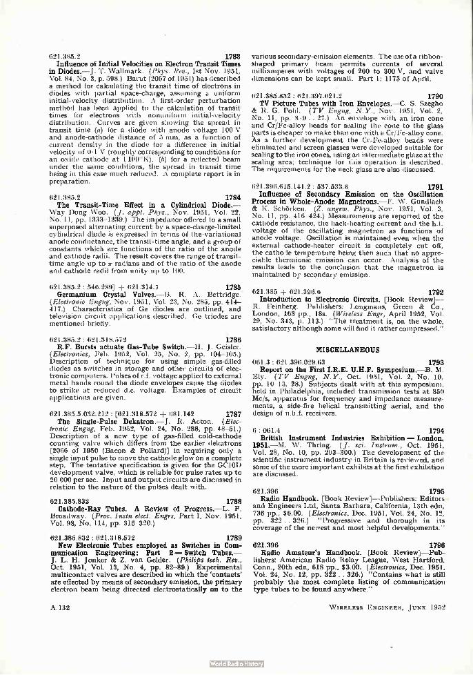
621.385.2 1783 Influence of Initial Velocities on Electron Transit Times
in Diodes.— J . T. Wallmark. (Phys. Rev., 1st Nov. 1951, Vol. 84, No. 3, p. 598.) Barut (2057 of 1951) has described a method for calculating the transit time of electrons in diodes with partial space-charge, assuming a uniform initial-velocity distribution. A first-order perturbation method has been applied to the calculation of transit times for electrons with nonuniform initial-velocity distribution. Curves are given showing the spread in transit time (a) for a diode with anode voltage 100 V and anode-cathode distance of 5 mm, as a function of current density in the diode for a difference in initial velocity of 0.1 V (roughly corresponding to conditions for an oxide cathode at 1 100°K), (b) for a reflected beam under the same conditions, the spread in transit time being in this case much reduced. A complete report is in preparation.
621.385.2 1784 The Transit-Time Effect in a Cylindrical Diode.—
Way Dong Woo. (J. appl. Phys., Nov. 1951, Vol. 22, No. 11, pp. 1333-1339.) The impedance offered to a small superposed alternating current by a space-charge-limited cylindrical diode is expressed in terms of the•variational anode conductance, the transit-time angle, and a group of constants which are functions of the ratio of the anode and cathode radii. The result covers the range of transit-time angle up to e radians and of the ratio of the anode and cathode radii from unity up to 100.
621.385.2 : 546.289] 621.314.7 1785 Germanium Crystal Valves.—B. R. A. Bettridge.
(Electronic Engng, Nov. 1951, Vol. 23, No. 285, pp. 414-417.) Characteristics of Ge diodes are outlined, and television circuit applications described. Ge triodes are mentioned briefly.
621.385.2: 621.318.572 1786 R.F. Bursts actuate Gas-Tube Switch.—H. J. Geisler.
(Electronics, Feb. 1952, Vol. 25, No. 2, pp. 104-105.) Description of technique for using simple gas-filled diodes as switches in storage and other circuits of elec-tronic computers. Pulses of r.f. voltage applied to external metal bands round the diode envelopes cause the diodes to strike at reduced d.c. voltage. Examples of circuit applications are given.
621.385.5.032.212: [621.318.572 -I- 681.142 1787 The Single-Pulse Dekatron.—J. R. Acton. (Elec-
tronic Engng, Feb. 1952, Vol. 24, No. 288, pp. 48-51.) Description of a new type of gas-filled cold-cathode counting valve which differs from the earlier dekatrons [2066 of 1950 (Bacon & Pollard)] in requiring only a single input pulse to move the cathode glow on a complete step. The tentative specification is given for the GC1OD development valve, which is reliable for pulse rates up to 20 000 per sec. Input and output circuits are discussed in relation to the nature of the pulses dealt with.
621.385.832 1788 Cathode-Ray Tubes. A Review of Progress.—L. F.
Broadway. (Proc. Instn elect. Engrs, Part I, Nov. 1951, Vol. 98, No. 114, pp. 316-320.)
621.385.832: 621.318.572 1789 New Electronic Tubes employed as Switches in Com-
munication Engineering: Part 2 — Switch Tubes.— J. L. H. Jonker & Z. van Gelder. (Philips tech. Rev., Oct. 1951, Vol. 13, No. 4, pp. 82-89.) Experimental multicontact valves are described in which the 'contacts' are effected by means of secondary emission, the primary electron beam being directed electrostatically on to the
A.132
various secondary-emission elements. The use of a ribbon-shaped primary beam permits currents of several milliamperes with voltages of 200 to 300 V, and valve dimensions can be kept small. Part 1: 1173 of April.
621.385.832: 621.397.621.2 1790 TV Picture Tubes with Iron Envelopes.—C. S. Szegho
& R. G. Pohl. (TV Engng, N.Y., Nov. 1951, Vol. 2, No. 11, pp. 8-9. . 27.) An envelope with an iron cone and Cr/Fe-alloy beads for sealing the cone to the glass parts is cheaper to make than one with a Cr/Fe-alloy cone. As a further development the Cr-Fe-alloy beads were eliminated and screen glasses were developed suitable for sealing to the iron cones, using an intermediate glaze at the sealing area; technique for this operation is described. The requirements for the neck glass are also discussed.
621.396.615.141.2 : 537.533.8 1791 Influence of Secondary Emission on the Oscillation
Process in Whole-Anode Magnetrons.—F. W. Gundlach & K. Sclitirken. (Z. angeze. Phys., Nov. 1951, Vol. 3, No. 11, pp. 416-424.) Measurements are reported of the cathode resistance, the back-heating current and the h.f. voltage of the oscillating magnetron as functions of anode voltage. Oscillation is maintained even when the external cathode-heater circuit is completely cut off, the cathode temperature being then such that no appre-ciable thermionic emission can occur. Analysis of the results leads to the conclusion that the magnetron is maintained by secondary emission.
621.385 -I- 621.396.6 1792 Introduction to Electronic Circuits. [Book Review]—
R. Feinberg. Publishers: Longmans, Green & Co., London, 163 pp., 18s. (Wireless Engr, April 1952, Vol. 29, No. 343, p. 113.) "The treatment is, on the whole, satisfactory although some will find it rather compressed."
MISCELLANEOUS
061.3: 621.396.029.63 1793 Report on the First I.R.E. U.H.F. Symposium.—B. M.
Ely. (TV Engng, N.Y., Oct. 1951, Vol. 2, No. 10, pp. 10-13, 28.) Subjects dealt with at this symposium, held in Philadelphia, included transmission tests at 850 Mc/s, apparatus for frequency and impedance measure-ments, a side-fire helical transmitting aerial, and the design of u.h.f. receivers.
6: 061.4 1794 British Instrument Industries Exhibition — London,
1951.—M. W. Thring. (J. sci. Instruni., Oct. 1951, Vol. 28, No. 10, pp. 293-300.) The development of the scientific instrument industry in Britain is reviewed, and some of the more important exhibits at the first exhibition are discussed.
621.396 1795 Radio Handbook. [Book Review]—Publishers: Editors
and Engineers Ltd, Santa Barbara, California, 13th edn, 736 pp., $6.00. (Electronics, Dec. 1951, Vol. 24, No. 12, pp. 322 .. 326.) "Progressive and thorough in its coverage of the newest and most helpful developments."
621.396 1796 Radio Amateur's Handbook. [Book Review]—Pub-
fishers: American Radio Relay League, West Hartford, Conn., 20th edn, 618 pp., $3.00. (Electronics, Dec. 1951, Vol. 24, No. 12, pp. 322. . 326.) "Contains what is still probably the most complete listing of communication type tubes to be found anywhere."
W IRELESS ENGINEER, JUNE 1952

ee eels. Ssgeo.-ectsig, Co., eleNe t%e M°
g, tbe CSN'it -tee@ of. Veted
csee *e e of v-sevee, -bettor
offes ie-9-çoiec
à ce2oeste sere it%e.‘40.0 eke
kbe "f',eèào "feetey • Yvkee
-tee, tleVétônee, elgetre COW.-
eop.%ee ee oeee f.o.ç tWee Va
v c« 0 w
vuel e -e\coeed. eitatete ,/4.e be
THE EDISON SWAN ELECTRIC COMPANY LIMITED 155 Charing Cross Road, London, W.C.2, and branches
Member of the A.E.I. Oroup of Cmibpaniea
W IRELESS ENGINEER, JUNE 1952
11
17

INSULATION RESISTANCE METER with variable test pressure
Designed for the measurement of high values of insulation resistance as experi-enced in modern materials and electrical components. Completely self-contained and mains-operated, providing its own D.C. test pressure. All essential voltages stabilised, giving constant readings even with fluctuating mains voltages as experi-enced under industrial conditions.
"MEGOHMMETER" MODEL RM 175—LZ
Complete prctection provided for the indicating meter against accidental over-loads as may be caused by a breakdown of the test sample or by selecting an incorrect range. Terminal leakage has been com-pletely overcome by the use of a special guard circuit, brought to an external terminal, enabling external extension leads or test fixtures to be conveniently connected.
RESISTANCE RANGE: 0 9 megohm to 10 million megohms. Basic range of scale, 9 to 503 megohms.
TEST PRESSURE: Continuously variable from 0 to 1000 V.D.C.
DIMENSIONS AND FINISH: 22 11- Y 8" steel cabinet finished in black-crinkle lacquer fitted with sloping front panel of silver anodised aluminium.
SET OF VALVES: Two ME 1400, one 6X5G, one 6SN7G, one U50, one HVR2, one EA50.
WEIGHT: 44 lbs.
SENSITIVE PANEL MOUNTING SI ZE 24" 34" RAN GE 25µA 10;tA
to to 50A 50A
Prices on application Available for immediate delivery from our Stockists, M.A. Supplies, Ltd., 68 New
Oxford Street, W.C.1, or write to:
METERS
5" 101/A to 50A
BRITISH PHYSICAL LABORATORIES HOUSEBOAT WORKS • RADLETT • HERTS Telephone: RADlen 5674-5-6
e-sote- akie When selecting stamping materials for the cores of small transformers, chokes, relays, etc., or shields and screening boxes to house them, it always pays to consult the acknowledged
specialists. There's a world of difference between
" transformer iron" and one of the Telcon high permeability nickel-iron alloys. The
difference is chiefly a matter of magnetic
performance.
ALLOYS
Each of the soft magnetic alloys of the Telcon Metals family is scientifically formulated and
processed, under laboratory control, to
possess a known combination of electrical and magnetic properties most suited to a particular
range of operating conditions. The practical advantages are that by selecting the grade
appropriate to a given application, useful savings in weight and bulk become possible with a worthwhile increase in efficiency.
Manufacturers are invited to write for technical advice and details of design data.
TELCON METALS TELcoe,1
11 THE TELEGRAPH CONSTRUCTION & MAINTENANCE CO., LTD.
(201, Head Office: 22 Old Broad Street, London, E.C.2. Telephone: LONdon Wall 7104 Enquiries to : Telcon Works, Greenwich, SE. 10. Telephone : GREenwich 3291
I • W IRELESS ENGINEER, JUNE 1952
SMALL BUT VERY GOOD!
TELEPHONE e 1:›
rrpt sc if I PATiben cjakne4
e "n ter see., 0 ,,
AuSTL
CAN
s, AFRIC
eat>
VS rAT
ofiKt.
,s,135
leme 44,115 st.14
4114) /e0ig
s14.04
110040 A*40
a .si.ov.• me'
Considering it is only the size of a matchbox the Type 5 Carpenter Polarized
Relay is capable of a surprisingly high performance providing answers to problems
in many fields of electrical engineering. Outstanding features of the Type 5 include:
HIGH OPERATIONAL SPEED • FREEDOM FROM CONTACT REBOUND
IMMUNITY FROM POSITIONAL ERROR • GOOD CONTACT PRESSURES
HIGH SENSITIVITY • ACCURACY OF SIGNAL REPETITION
RUGGED DESIGN • EXCEPTIONAL THERMAL STABILITY
Plug or soldes tag base optional.
Dimensions —(With cover. Excluding connecting pins.) 2fil ins. high. 1-176- ins, wide. in. deep. Weight (including socket) 4.8 oz. (137 gm.)
complete specification and further details of the com-plete range of Carpenter Relays may be had on request.
CARPENTER POLARIZED
RELAY TYPE Alamtlactured hy the Sole Liern.wes
TELEPHONE MANUFACTURING CO. LTD Cmoroctors to Governments of the British Commonwealth and other Nations.
HOLLINGSWORTH WORKS • DULWICH • LONDON S.E.21 Telephone: Gipsy Hill 2211 (10 lines)
W IRELESS ENGINEER, JUNE 19.-C2 19
Another of
BROOKES
famous
CRYSTALS
TYPE "M" Frequency range: 8 Mc s to 17 Mc/s.
There's one for your purpose
Quartz crystal plate of appropriate cut and dimensions to suit the frequency requirement. mounted in an hermetically sealed metal can, contact pins passing through glass seals spaced at .490" centres and fitted with silver-plated sleeves h- diameter. Dimensions of holder: -75" high under pins, -75' wide, •375" thick. Frequency tolerance is ±0-01^;, of nominal at 20`C., or better for special applications. Frequency-temperature coefficient better than 2 parts in 10. per 1°C. over temperature range of —2frC. to I-70'C.
ROOK ES CRYSTALS LIMITED 10 Stockwell St., Greenwich, London , S.E.I 0 1'hone • Gr rns . Xt aals, Green, London
GREenw:ch 1828 Cab'les: Xtls, London.
THE LATEST in
AIR DIELECTRIC TRIMMERS
Encased in acetate con-tainer for extra protection Width 16.5 mitn. Length: 2.2 in III
Height: 1.5 to 8pF-7.5 min.. I 20pF-10 mom. Sto 26pF-11 2 to 32pF-12 m/m. Law, Straight line capacity. Power Factor: Lena than .001 Insulation: over 2,1:01: megohme. Voltage: 500 D.C. Type
appeared Cat. A. No. 464
DEVELOPMENTS CO. LTD. ULVERSTON NORTH LANCS TEL.: ULVERSTON 3306
•et‘ r THE SCIEN I(
VALVE
BRITISF, 1,1!01
774Ó1f.i.a1 a ,ff. etesel.;dele
at ' ,tad i4dleete
Ç s
‘teeU‘S 0S‘7 ;.‘1 ugt S vi 06e/5 00C
s
Gtk5 ‘-t‘‘ot•Aele etec
GREENHILL CRESCENI", HARROW-ON-THE-HILL, MIDDX. Telephone: HARrow 2655
SPECIALISED REPAIR SERVICE
WEBB'S Radio specialise in the repair and alignment of
comp:ex communication receivers All makes of British and American communication receivers completely overhauled to satisfy makers' original test specification. Calibration over entire coverage of tuning range. We issue a test report giving sensitivity—selectivity—signal/noise ratio on I.F's, and sensitivity—image ratio—signal/ noise—A.V.C. characteristics overall.
Recognised Service Agents for EDDYSTONE, R.C.A., HALLICRAFTER, etc.
WEBB'S RADIO 14 Soho Street, London, W.I. Gerrard 2089.
APPOINTMENTS—The engagement of persons answering these advertisements must be made through the local office of the Ministry of Labour and National Service, etc., if the applicant is a man aged 18-64 or a woman 18-59 inclusive, unless he or she or the employer is
excepted from the provisions of The Notification of Vacancies Order, 1952.
Murphy Radio Ltd., wish to appoint a chief radio and television receiver designer to take charge of their electrical design laboratory. The successful applicant must possess good academic qualifica-tions, preferably with some research experience and followed by several years in an industrial organisa-tion engaged in television or allied fields. The post is pensionable and the salary paid will
be commensurate with the high standard of qualifi-cations required. Applications, which will be treated in strict confidence, should be addressed to the Director of Engineering, Murphy Radio, Ltd., Welwyn Garden City, Herts.
oitage Laboratoriv› Lid- require the following staff: —
(a) Project leader to control a division of electronic and electro-mechanical engineers. The applicant should be capable ol leading a team of research and development engineers in a highly technical field. Starting salary will be according to ability, experience and age.
(b) Senior electronic and electro-mechanical physicists or engineers. A physical and experimental outlook is desirable. The applicants must be capable of designing modern elec-tronic circuits and of leading a group of assistant engineers. Starting salary according to age and experience.
(e) Assistant Engineers interested in electronics and small mechanisms.
There are prospects of rapid promotion in an expanding laboratory. Five-day week, exœllent canteen and active sports club. Apply stating age, nationality, previous experience and salary
required to the Manager, Cottage Laboratories Ltd., Portsmouth Road, Cobham, Surrey.
211 WIRELESS ENGINEER, JUNE 1952
in the range o.00 [J.H to
3omH, the ̀ CIINTEL' Mutual and
Self Inductance Bridge will be
found unequalled for accuracy and
simplicity of use. Also measuring
resistance in the range lootat to
3000n, this bridge is an essential
piece of laboratory equipment,
full details of' which are available
on request.
LIMITED CINEMA-TELE VISION A Company within the J. Arthur Rank Organisation
WORSLEY BRIDGE ROAD • LONDON • SE 26 Telephone: HITher Green 4600
SALES AND SERVICING AGENTS F. C. Robinson & Partners Ltd., H. Hawnt & Co., Ltd., Atkins, Robertson & Whnetord Ltd.. 287 Deansgate, Manchester, 3 59 Moor St., Birmingham, .1 too Torrisdale Street, Glasgow, S.2 eù.‘
UNTEL 1STERED TRADE MARI.
-W IRELESS ENGINEER, JUNE 1952 21
Jetimminummuniumiummummuniummimmumumummuimmumme: E THE WORLD'S GREATEST BOOKSHOP E
E £5
• FOR. BOOIGO• =
New and secondhand Books on every subject. Fe _ Stock of over 3 million volumes. E
= 119-12S, CHARING CROSS ROAD. LONDON, W.C.2 = , = = E Gerrard 5660 (16 lines) * OPEN 9-6 (inc. Sat.) =
=Timonium' nimumium innumnimummuniummummumuumumme
Engineer of degree standard, B.Sc., engineering desirable. required
for design and development of power capacitors. Should hase
knowledge of di-electrics and measurements. APPIY Box 0009.
c/o Wireless Engineer.
Development Engineer with knowledge of metallurgy and
electronics required for experimental work on ultrasonics in
Research Department of scientific instrument makers in N.F.
London area. Age 25/35.—Write stating experience and seta'',
required to Box 0010, c/o Wireless Engineer.
Specialist required with expert knowledge of development and
production of carbon potentiometer tracks—Apply Chief Engineer.
Box 0011, cio Wireless Engineer.
S. Smith & Sons (England). Ltd., Bishops Cleeve. Cheltenham. require the following staff:—
Senior Engineer—to lead a section in the design and development of small servo systems including the application of gyroscopic and
magnetic amplifier technique. This is a permanent post and carries superannuation benefits, and housing assistance will be given to successful applicant. Commencing salary £900 to £1,200 dependent on age, qualifications and experience. Ref. 4/EN/G.
Senior Mechanical Engineer—to control design and development
of a wide range of Aircraft Instruments and allied equipment. Applicants should have a sound technical education with previous design experience in pressure-sensitive elements and intricate
mechanisms. Salary £900 to £1,200 depending upon age and experience. Ref. 5/EN/M.
Development Engineers—for development of high-grade test
equipment in connection with manufacture of automatic pilots and aircraft instruments. Work involves application of electronic techniques over a frequency range from zero to approximately
100 kc. p.s. together with light electrical and mechanical engineering.
Preference will be given to applicants with experience of applied .measurements in one or more of the above engineering fields but the foremost qualification is a sound appreciation of fundamental engin-
eering principles. Salary according to qualifications and experience. Ref. I/EN
Development Engineers—senior and junior engineers experienced
in the design of electronic test equipment including valve voltmeters.
C.R.O.. oscillators, etc. Applicants will be responsible for the development of research models to the production stage and must have a good fundamental knowledge of electrical theory and
practical experience of design. Salary dependent on qualifications and experience. Ref. 2/EN.
Development Engineers—for work on auto control and servo
systems. Applicants with experience in low frequency electronic techniques, including the use of magnetic amplifiers. Preference
given to those with previous experience in designing equipment for aviation requirements. Salary according to qualifications and experi-ence. Ref. 3/EN.
Write quoting Reference Numbers and giving qualifications and experience to the Personnel Mahager.
Belling & Lee. Ltd.. Cambridge Arterial Road, Enfield, Middlesex. require research assistants in connection with work on electronic components, fuses, interference suppressors and television aerials. Applicants must be graduates of the I.E.E. or possess equivalent qualifications together with similar laboratory experience. Salary mill be commensurate with previous experience: five-day week. contributory pension scheme. Applications must be detailed and concise, and will be treated as confidential.
Ferranti. Ltd.. have immediate vacancies for men with electrical engineering qualifications to undertake the advanced testing of Naval Anti-Aircraft Fire Control Equipment involving electronics and servo mechanisms either in firms workshops or on board H.M. Ships in Home Ports. Salary in accordance with age and experience between £356 and £650 per annum. Normal expenses plus a generous allowance are paid when working out.
Previous experience of this type of work, though desirable, is not essential. Forms of application from Mr. R. J. Hebbert. Staff Manager. Ferranti, Ltd., Hollinwood, Lancs. Please quote ref. H.G.N.
The General Electric Co.. Ltd., Brown's Lane. Coventry. have vacancies for Development Engineers. Senior Development Engineers. Mechanical and Electronic, for their Development Laboratories on work of national importance. Fields include microwave and pulse applications. Salary raiiste £400-£1.250 per annum. Vacancies also exist for Specialist Engineers in component design, valve applications. electro-mechanical devices and small mechanisms. The Company's Laboratories provide excellent working conditions with social and welfare facilities. Superannuation Scheme. Assistance with housing in special cases. Apply by letter stating age and experience to The Personnel Manager (Ref. CHC.).
One or two experienced radar or electronic engineers, also engineers experienced in servo mechanisms are wanted for a Guided Weapons project by English Electric Laboratory, Luton. Pro-gressive Post with a starting salary of £600 to £1,000 per annum according to experience. Write, giving full details quoting Ref. 456H, to Central Personnel Services, English Electric Co.. Ltd. 24/30 Gillingham Street, London, S.W.1
Post Graduate and Final Year university students in physics, electrical and mechanical engineering and metallurgy are invited to send details of their records to the Staff Manager (Ref. GBLC/S/876). Research Laboratories of The General Electric Co., Ltd.. Wembley. Middlesex. A number of openings in interesting experimental research will be available during the coming months for men with outstanding ability and qualifications.
Engineers and physicists with experience in the following fields arc required by the G.E.C. at the Stanmore Laboratories: (a) servo-mechanisms. (h) microwave aerials, transmitters or receivers. (c) small mechanisms, (d) electronic circuitry, (e) D.C. amplifiers, (f) test gear for field trials. Preference will be given to men with good academic qualifications. Applications should be sent to the Staff Manager (Ref. GBLC/875). G.E.C. Research Laboratories. Wembley, Middlesex.
Two graduates, gene senior, tale , naluired for work in Electronics Section of laboratory engaged I,, Physics Research. The function of the Eleetrt lll l . Beaton ix primarily to clesign and build rontrol and ineaeuring gear for the laboratory, includitig Sertioux working q, k:leetron Microscopy, Nuclear Physics, Semi-Conductors and Physical Retell irgy. Two other paids are vacant for wt on new project requiring men with l'h.
or h lllll airs degree and at least two yearn• potet-graduate experienee and having interest in work on radio frequency power violate.
Applications in writing stating age, qualifications and expertes,. to Personnel (titter. Associated Electrical Industries Limited, Research Laboratory, Aldermaston Court, Aldermaston. Berkshire.
Scientific Computer required to assist with design, development and research work in connection with electrical networks. Minimum qualifications: Inter degree or Higher School Certificate including Mathematics. Experience in Computing. Mathematics. Physics or Engineering desirable. Initiative and interest in Mathematics and numerical work essential. Good salary and conditions of service. Apply Personnel Department. Telephone Manufacturing Co.. Ltd.. Sevenoaks Way. St. Mary Cray. Kent.
22 W IRELESS E NGINEER, JUNE 195'..,

QUARTZ CRYSTAL ACTIVITY TEST SET
UNSURPASSED AS A SIMPLE & ACCURATE INSTRUMENT
FOR THE MEASUREMENT OF CRYSTAL PERFORMANCE
The G.E.C. Quartz Crystal Activity Test Set measures the equivalent parallel resistance of a quartz crystal when oscillating in a circuit having an input capacity of either 20 pF. 30 pF or 50 pF, the alternative capacities being selected by a switch.
The dial is calibrated and has a range of 4 kilohms to 130 kilohms and is direct reading. No calculation is necessary. Measurements can be made at any con-venient amplitude of oscillation up to 10V. R.M.S. at the crystal terminals for crystals of normal activity.
The accuracy of the loss dial calibration is ± 2%.
WRITE FOR DESCRIPTIVE LEAFLET_
SALFORD ELECTRICAL INSTRUMENTS LTD. PEEL WORKS : SILK STREET . SALFORD : LANCS. Subsidiary of THE GENERAL ELECTRIC CO. LTD. OF ENGLAND
W I KELESS ENGINEER, JUNE 1932 23
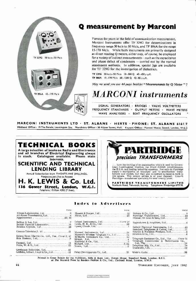
Q measurement by Marconi
Famous for years in the field of communication measurement, Marconi Instruments offer TF 329G for determinations in frequency range 50 kc/s to 50 Mc/s, and TF 886A for the range 15-170 Mc/s. While both instruments are primarily designed as direct reading Q meters, either may, of course, be employed
for a variety of indirect measurements—such as the capacitance and phase defect of condensers — carried out by the normal reasonance methods. In addition, special jigs are available for TF 329G for the investigation of dielectrics.
TF 329G 50 kcis - 50 Mc/s 10-500 Q 40-450p it F.
TF 886A 15-170 Mcis 60-1200 Q 12-85 p. p. F.
May we send you our 44-page booklet "Measurements by Q Meter " ?
MARCONI instruments SIGNAL GENERATORS • BRIDGES • VALVE VOLTMETERS
FREQUENCY STANDARDS • OUTPUT METERS • WAVE METERS
WAVE ANALYSERS • BEAT FREQUENCY OSCILLATORS
MARCONI INSTRUMENTS LTD • ST. ALBANS • HERTS • PHONE: ST. ALBANS 6161 7 Midland Office : 19 The Parade, Leamington Spa. Northern Office : 30 Albion Street, Hull. Export Office Marconi House, Strand, London, W.C.2
TECHNICAL BOOKS A large selection of books on Radio and Electronics and all branches of Electrical Engineering always in stock. Catalogues available. Please state
interests.
SCIENTIFIC AND TECHNICAL LENDING LIBRARY
Annual Subscription from TWENTY—FIVE SHILLINGS. Prospectus post free on Request
H. K. LEWIS & Co. Ltd • I 36 Gower Street, London, W.C.I.
Telephone : EUSton 4282 (7 lines).
PAGE
Ah-mec Laboratories, Ltd. All-Power Transformers, Ltd Appointments 20, 22
Belling & Lee, Ltd 7 British Physical Laboratorie • 18 Brookes Crystals, Ltd 20
Cinema-Television,!, tcl. 21
Edison Swan Electric Co., Ltd., The. Cover ii, 17 Erie Resistor, Ltd
Ferranti, Ltd 13 Foyle, W. 8c G., Ltd 22
Goodmans Industries, Ltd 12 Griffiths, Gilbert, Lloyd & Co., Ltd 10
PARTRIDGE precision TRANSFORMERS
... have the barking of an organisation which is used by Govern-ment Experimental Stations, the Royal Aircraft Establishment, the B.E.A. and leading industrial concerns. Not only do Partridge supply a multiplicity of 'standard' and 'to specification' trans-formers and chokes, but they also co-operate in research work in this sphere. This unique service is at your disposal. ConFolt Partridge—transformer specialists for over twenty years.
PARTRIDGE TRANSFORMERS LIMITED Roebuck Road, Tolworth, Surrey. Telephone: Elmbridge 6737,8.
Index to Advertisers
PAGE
Hassett & Harper, Ltd Hivac, Ltd
PAGE
12 Painton & Co., Ltd 1 20 Partridge Transformers, Ltd 24
Pitman, Sir Isaac & Sons, Ltd 10
Leland Instruments, Ltd Cover iv Lewis, H. K., & Co., Ltd "4 Lyons, Claude, Ltd 1
Marconi Instruments, Ltd 24 Marconi's Wireless Telegraph Co., Ltd 14 McMurdo Instrument Co., Ltd 10 NI iltoid, Ltd. 4 Muirhead & Co., Ltd 2 Mollard, Ltd 3, In Murex, Ltd 2
Reproducers & Amplifiers, I.td
Salford Electrical Instruments, I td 23 Standard Telephones & Cables, Ltd 11 Steatite & Porcelain Products, Ltd Stratton & Co., Ltd 4
Telegraph Condenser Co., Telegraph Construction
Ltd., The Telephone Mfg. Co.,. Ltd 10 Transradio, Ltd 12
Ltd., The Cover iii & Maintenance Co.,
18
Oxley Developments Co., Lid 20 Webb's Radio 20
Printed in Great Britain for the Publishers, life & Sons, Ltd.. Dorset House. Stamford Street, London. S.E.1. at The Baynard Press by Sanders Phillips & CO., Ltd., Chryssell Road, London. S.W.9.
24 W IRELESS ENGINEER, JUNE 1952
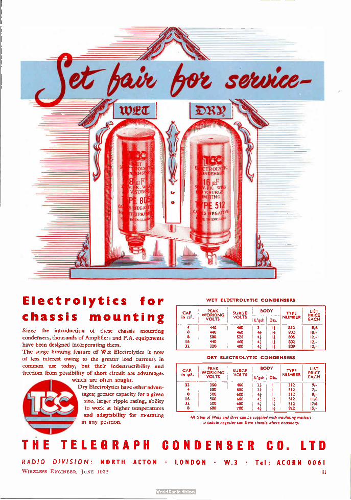
Electrolytics for
chassis mounting Since the introduction of these chassis mounting
condensers, thousands of Amplifiers and P.A. equipments
have been designed incorporating them.
The surge limiting feature of Wet Electrolytics is now
of less interest owing to the greater load currents in
common use today, but their indestructibility and
freedom from possibility of short circuit are advantages
which are often sought.
Dry Electrolytics have other advan-
tages; greater capacity for a given
size, larger ripple rating, ability
to work at higher temperatures
and adaptability for mounting
in any position.
WET ELECTROLYTIC CONDENSERS
CAP. in p.F.
PEAK WORKING VOLTS
, 1 SURGE BODY TYPE r VOLTS r NUMBER'
, L'gth Dia. ,
4 440 460 3 , II 812 8 440 460 41- ' II 802 8 500 525 44 r lj 805 16 440 460 41- , It 802 32 320 400 4-4 ! II ' 809
LIST PRICE EACH
8/6 10:-
12,-
DRY ELECTROLYTIC CONDENSERS
CAP. PEAK WORKING SURGE
in ilF! r VOLTS VOLTS Ligth
32 350 400 : 24 4 500 600 24 ! 8 500 600 : 44 ; 16 500 600 44 i 32 500 600 44 r 8 600 700 r ;
BODY TYPE !
Dia. rr NUMBER'
1 r 312 I 512 I 512 14 512 14 512 11 922
LIST PRICE EACH
9/-7/-8/-11/6 17/6 15/.
All types of Wets and Drys can be supplied with insulating washers
to isolate negative can from chassis where necessary.
THE TELEGRAPH CONDENSER CO. LTD RADIO DIVISION : NORTH ACTON • LONDON • W.3 • Tel: ACORN 0061
W IRELESS ENGINEER, JUNE 1952
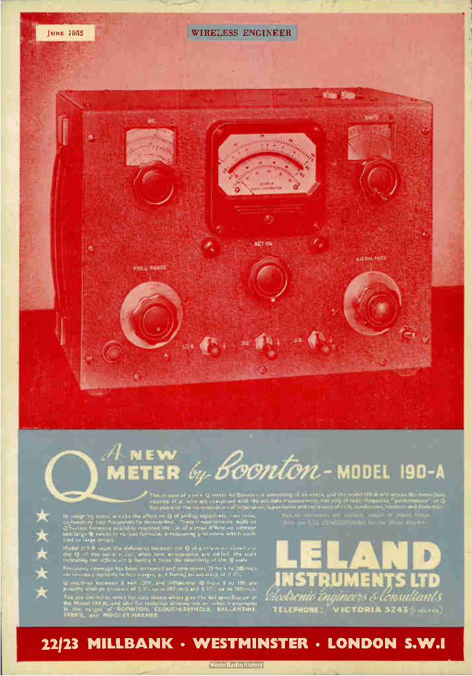
JUNE 1952
A NEW METER 100/tert- MODEL 190-A
The re ease of a new Q meter by. Boonton is something of an evert, und th model 190-A will arouse eh= immediate interest or All who are concerned with the accurate measurement, not only of radio frequency " performance or Q but also wit!. the determination of inductance, capacitance and resistance of coils, condensers, resistor; and dielearics.
In designing tuned circLits the effect on Q of adding capacitors, iron cores, criresisturs must frequently be determined. These measurements made on Q meters formerly available required the use or a small difference oetween two larte Q values in various formulo, a measuring procedure which could had to large errors.
Model 190-A reads the difference betwem toe Q of a reference circuit and the Q cf the same ci.-cuit when new components are added, the scale indicating the differenticl Q having 4 times the sensitiaity of the Q scale.
Freguency coverage has, been increased and now. covers 20 mc s to 260 mc/s continuously variable in four ranges, and having an accuracy of ±
Q readings between 5 and 1200, and differential Q from O to 100 are possible with an accuracy of ± 5", up to 100 mc/s and ±12., up to 260 mc/s.
You are invited to write for data sheets whicn give the full specification of the Mociel 190-A, and also for technical infaimation on other instraments in the ranges of BOONTON, CLOUGI4BRENGLE, BALLANTINE, FERRI5, and MIDGLEY-HARMER.
Boonton instrutœnt, ore available, subject to import Ponce.
fro'', the SOLE CC NCESSIONA/RES far the UnIted
E LAN D NSTMUMENTS LTD
eieeetefik enyúzeeu Cbmetiteenéd TELEPHONE: VICTORIA 3243 vEll›Es)
22123 M1LLBANK • WESTMINSTER • LONDON S.W.I