Embed Size (px)
Citation preview

Paper number: 12(2014)2, 288, 153 - 158
THE JOINTS OF COLD-FORMED PURLINSDr Alexander Danilov* Moscow State University of Civil Engineering, Russia
Olga TusninaMoscow State University of Civil Engineering, Russia
doi:10.5937/jaes12-5764
Original Scientific Paper
Two problems of purlin design related to bending moment distribution in continuous and in simply
supported purlin are considered. Bending moment redistribution in purlin may be realized using
bearing spring (BS) elements. Preliminary results of numerical experiments show the substantial
reduction of bending moments in purlin thus obtaining less section heights and web thicknesses.
The approach to reduction of internal forces in purlins may help in resolving some problems typical
for cold-formed thin-walled structures. There may be also some optimization possible relating BS-
elements lengths and thicknesses and cross sections.
Key words: Cold-formed thin-walled profiles, Z-section, Purlin, Bending moment redistribution,
Bearing spring elements
INTRODUCTION
Cold-formed, thin-walled construction used to be limited to applications where weight savings were of primary concern, such as the aircraft and automotive industries. However, following improvements in manufacturing techniques, corrosion protection, product availability, under-standing of the structural response and sophisti-cation of design codes for cold-formed sections, light-gauge construction has become increas-ingly widespread. Light-gauge sections used in conjunction with hot-rolled steelwork is now commonplace.
BACKGROUND
The use of thin, cold-formed material brings about a number of special design problems that are not generally encountered when using ordi-nary hot-rolled sections. These include [04]:
non-uniform distribution of material proper-ties due to cold-working
rounded corners and the calculation of geo-metric properties
Local buckling
Distortional buckling
Torsional and flexural torsional buckling
shear lag
flange curling
web crushing, crippling and buckling.
•
•
•
•
•
•
•
•
These effects will not be outlined directly in this paper. But some aspects as being in closest re-lation with it and namely internal forces and mo-ment distribution and how it depends on joint ar-rangements and their positioning are considered here and some simple conclusions are made and special joint arrangements offered.
There are many of researchers working on the problems of purlin connections. So, in the papers [01, 02, 07, 08, 09] experimental and theoreti-cal investigations of connections between cold-formed steel Z sections are represented.
RESEARCH
The main features of the problem can be seen best considering simultaneously two classical problems of purlin design. One is for bending moment distribution in continuous beam and the other one relates to the simply supported beams.
Consider a 5-span Z-section uniform continu-ous purlin under uniformly distributed transver-sal load acting downwards (Figure 1). From the moment diagram one may see that moving right the first (extreme left) support reduces the mo-ment on the second support thus equalizing it with that on any other intermediate support. Oth-erwise it would be reasonable to reinforce the purlin in this span and in some extent of the sec-ond span. The same applies to the extreme right simply supported end of the purlin.
153* Moscow State University of Civil Engineering Russia, 129337,
Moscow, Yaroslavskoe shosse, 26; [email protected]
Journal of Applied Engineering Science 12(2014)2
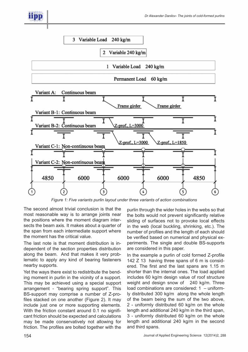
The second almost trivial conclusion is that the most reasonable way is to arrange joints near the positions where the moment diagram inter-sects the beam axis. It makes about a quarter of the span from each intermediate support where the moment has the critical value.
The last note is that moment distribution is in-dependent of the section properties distribution along the beam. And that makes it very prob-lematic to apply any kind of bearing fasteners nearby supports.
Yet the ways there exist to redistribute the bend-ing moment in purlin in the vicinity of a support. This may be achieved using a special support arrangement - “bearing spring support”. This BS-support may comprise a number of Z-pro-files stacked on one another (Figure 2). It may include just one or more supporting elements. With the friction constant around 0.1 no signifi-cant friction should be expected and calculations may be made conservatively not allowing for friction. The profiles are bolted together with the
Figure 1: Five variants purlin layout under three variants of action combinations
purlin through the wider holes in the webs so that the bolts would not prevent significantly relative sliding of surfaces not to provoke local effects in the web (local buckling, shrinking, etc.). The number of profiles and the length of each should be verified based on numerical and physical ex-periments. The single and double BS-supports are considered in this paper.
In the example a purlin of cold formed Z-profile 142 Z 13 having three spans of 6 m is consid-ered. The first and the last spans are 1.15 m shorter than the internal ones. The load applied includes 60 kg/m design value of roof structure weight and design snow of 240 kg/m. Three load combinations are considered: 1 – uniform-ly distributed 300 kg/m along the whole length of the beam being the sum of the two above, 2 - uniformly distributed 60 kg/m on the whole length and additional 240 kg/m in the third span, 3 - uniformly distributed 60 kg/m on the whole length and additional 240 kg/m in the second and third spans.
154 , 288
Dr Alexander Danilov- The joints of cold-formed purlins

Journal of Applied Engineering Science 12(2014)2
Figure 2: BS double support (the profiles are cut at the girder symmetrically
RESULTS
The moment distributions were obtained using computer program LIRA 9.6 for all five purlin and support arrangements presented schematically in Figure 1. These diagrams (Figure 3-5) are pre-sented for each of the three load combinations. It shows how the BS-supports take off the bend-ing moments from the purlin beam thus reducing significantly the danger of local effects.
Figure 3: Moment distributions under Combination 1. From top downwards go the arrangements A, B-1,
B-2, C-1 and C-2
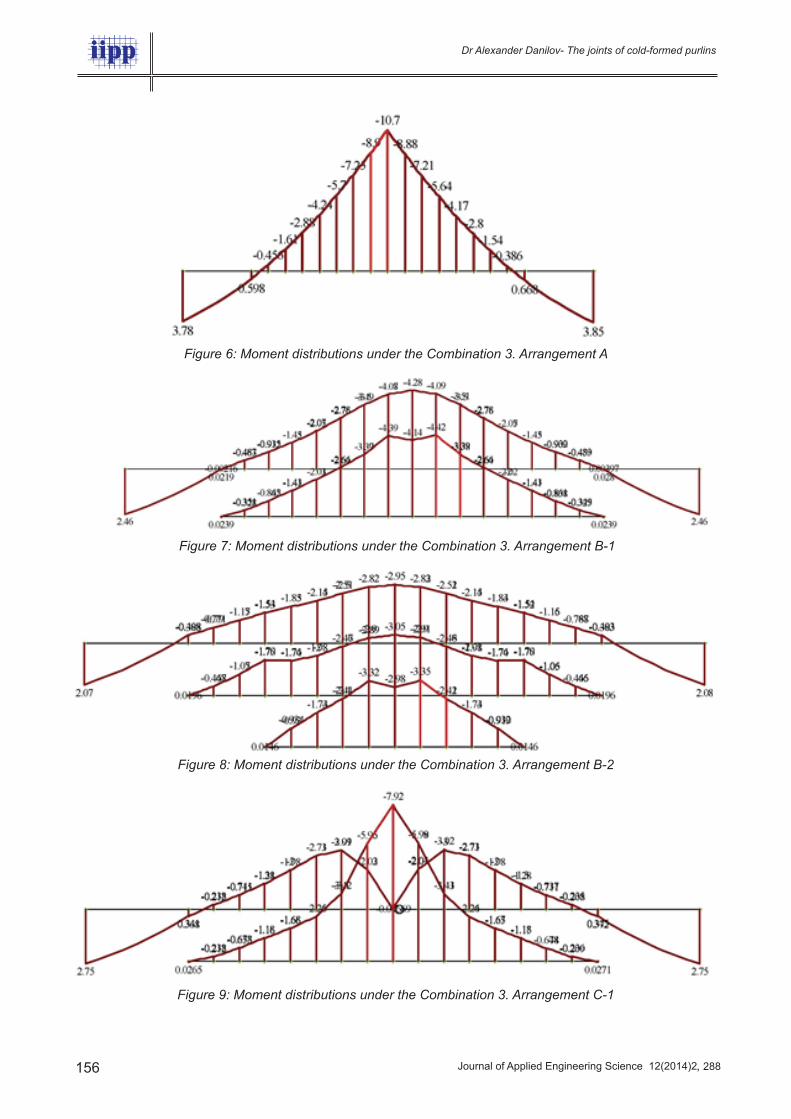
For this last case some more detailed results are given in Figure 6-10 in graphical form. Yet even in above three pictures it can be seen that ad-ditional elements of BS-supports very effectively discharge the purlin making it possible to use the lighter steel sections. For single BS-supports there it seems to be not too much of technologi-cal problems. As for the double BS-supports (B-2 and C-2) there exist some problems that may be effectively solved by those concerned. For the lower BS-element a special nonstandard cross-section may be needed because of the flange lips (in Figure 1 no lips shown), Figure 11.
Below the moment distributions nearby the sup-port number 3 under the load case 3 are given as an example for each of 5 support arrange-ments. The bending moment values are given in kNm.
Figure 4: Moment distributions under Combination 2. From top downwards go the arrangements A, B-1,
B-2, C-1 and C-2
Figure 5: Moment distributions under Combination 3. From top downwards go the arrangements A, B-1,
B-2, C-1 and C-2
155, 288
Dr Alexander Danilov- The joints of cold-formed purlins
Journal of Applied Engineering Science 12(2014)2
Figure 6: Moment distributions under the Combination 3. Arrangement A
Figure 7: Moment distributions under the Combination 3. Arrangement B-1
Figure 8: Moment distributions under the Combination 3. Arrangement B-2
Figure 9: Moment distributions under the Combination 3. Arrangement C-1
156 , 288
Dr Alexander Danilov- The joints of cold-formed purlins

Journal of Applied Engineering Science 12(2014)2
Figure 10: Moment distributions under the Combination 3. Arrangement C-2
157, 288
Dr Alexander Danilov- The joints of cold-formed purlins
The cases C-1 and C-2 are for non-continuous purlin having gaps on the supports.
Table 1: Maximum bending moments in different arrangements
1 Uniform Load 60 + 240 = 300 kg/m in all spans
Variant of Support A B-1 B-2 C-1 C-2
Max Deflection (-) 42 30 27 35 28
Mmax
- Support (-) 887 518 372 360 255
Mmax
- Span 445 355 314 392 330
Mmax
- Upper Det (-) 370 400 882 634
Mmax
- Lower Det (-) 476 563
2 Uniform Load 60 kg/m in all spans plus 240 kg/m in the 3rd span
Max Deflection (-) 83 26 21 28 22
Mmax
- Support (-) 626 367 242 335 223
Mmax
- Span 700 325 290 343 237
Mmax
- Upper Det (-) 509 262 612 303
Mmax
- Lower Det (-) 427 473
3 Uniform 60 kg/m in all spans plus 240 kg/m in the 2nd and 3rd spans
Max Deflection (-) 59 26 21 30 23
Mmax
- Support (-) 1066 428 295 342 253
Mmax
- Span 552 327 290 351 300
Mmax
- Upper Det (-) 442 305 792 432
Mmax
- Lower Det (-) 427 476
Parameter A B-1 B-2 C-1 C-2
Mmax (purlin only) 1066 518 372 392 330
Wreq
for Steel S235 Ry = 23 kN/cm2 46 23 16 17 14
Cross section232 Z 20
172 Z 14
142 Z 13
142 Z 20
142 Z 13
Specific weight (purlin only), kg/m 5.87 3.41 2.84 3.05 2.84
Max moment - all elements, kN•m 1056 518 476 882 634
Wreq
for Steel S235 Ry = 23 kN/cm2 46 23 21 38 28
Cross section232 Z 20
172 Z 14
172 Z 13
232 Z 18
202 Z 14
Specific weight (cross section), kg/m 5.87 3.41 3.25 4.88 3.82
Weight (A – allowing for overlaps 2x0.25 m, and BS elements for the rest), kg/m
6.36 5.12 5.89 7.32 6.92
From Table 1 follow the maximal values for the purlin in each arrangement.
Table 1: Maximum bending moments and purlin sections for different arrangements

Journal of Applied Engineering Science 12(2014)2 158 , 288
Dr Alexander Danilov- The joints of cold-formed purlins
CONCLUSION
These preliminary results of numerical experi-ments show the way to redistribute bending moments in purlin thus obtaining less section heights and web thicknesses. The reduction of internal forces in purlin may help in solving some problems typical for overlaps. There may be also some optimization possible relating BS-elements lengths and thicknesses.
Figure 11: Example of double BS-element support arrangement with nonstandard cross section
The possible specific solutions may be valid of course only allowing for all effects concerning various modes of buckling and other possible problems typical for thin gauge plated elements using the results in a number of publications [03, 05, 06, 10, 11, 12, 13, 14].
REFERENCES
Chung K.F., Ho. H.C. (2005) Analysis and design of lapped connections between cold-formed steel Z-sections, Thin-walled struc-tures, Vol. 43, Iss. 7, pp. 1071-1090
Chung K.F., Ho H.C. (2004) Structural behav-iour of high strength cold-formed steel Z-purlins with overlaps, Seventeenth International Spe-cialty Conference on Cold-Formed Steel Struc-tures, Orlando, Florida, USA, Pp. 777-798
Epstein H., Murtha-Smith E., Mitchell J. (1998) Analysis and design assumptions for continuous cold-formed purlins, Practice Pe-riodical on Structural Design and Construc-tion, Vol. 2, No. 2, pp. 60-67
1)
2)
3)
Gardner L., Nethercot D. (2011) Designers’ Guide to Eurocode 3: Design of Steel Buildings. EN 1993-1-1, -1-3 and -1-8. Second edition, 161 p.
Hancock G.J., Celeban M., Healy C., Georgiou P.N., Ings N. (1990) Tests of purlins with screw fastened sheeting under wind uplift, NBS Spe-cial Publication No. 577, National Bureau of Standard, Washington DC, USA, pp. 319-419
Hancock G.J., Celeban M., Healy C. (1992) Tests of continuous purlins under downwards loading, Proceedings of Eleventh International Specialty Conference on Cold-Formed Steel Structures, St. Louis, Missouri, USA, pp. 155-179
Ho H.C., and Chung K.F. (2002) An experimen-tal investigation into lapped moment connec-tions between Z sections, Proceedings of the Third International Conference on Advances in Steel Structures, Hong Kong, pp. 437-444
Ho H.C., and Chung K.F. (2004) Experimen-tal investigation onto the structural behaviour of lapped connections between cold-formed steel Z sections, Thin-Walled Structures, Vol. 42, Iss. 7, pp. 1013-1033
Ho H.C. and Chung K.F. (2002) Structural anal-ysis on lapped moment connections between cold-formed steel Z sections, Proceedings of the Second International Conference on Sta-bility and Dynamic, Singapore, pp. 675-680
LaBoube R.A. (1988) Behavior of continuous span purlin system, Ninth International Con-ference on Cold-Formed Steel Structures, St. Louis, Missouri, USA, pp. 191-203
Luza G., Robra J. (2008) Design of Z-pur-lins: Part 1. Basics and cross-section values according to EN 1993-1-3, Proceedings of the 5th European Conference on Steel and Composite Structures EUROSTEEL, Graz, Austria, pp. 129-134
Luza G., Robra J. (2008) Design of Z-purlins: Part 2. Design methods given in Eurocode EN 1993-1-3, Proceedings of the 5th European Conference on Steel and Composite Structures EUROSTEEL, Graz, Austria, pp. 135-140
Sokol L. (1988) Aspects of the design of purlins in Z-sections, Der Metallbau im konstruktiven Ingenieur-bau (Festschrift R. Baehre), Karlsruhe, pp. 341-358
Sokol L. (1996) Stability of cold-formed pur-lins braced by steel sheeting, Thin-Walled Structures, Vol. 25, No. 4, pp. 247-268
4)
5)
6)
7)
8)
9)
10)
11)
12)
13)
14)
Paper sent to revision: 24.03.2014.
Paper ready for publication: 21.05.2014.