Embed Size (px)
Citation preview
A 2015.01.12 W.H.JUNG H. LEE D.K. JI FOR INFORMATION
Rev Date Prepared Checked Approved Details of Revision
Owner
Contractor
Sub-Supplier
Project
RUTENBERG POWER STATION UNIT 1 & 2
FGD WASTE WATER TREATMENT SYSTEM
PC
S09091
UAS Code
CQ03
Date Name Scale Unit Code
12
Prepared Title
ERECTION & INSTALLATION
PROCEDURE FOR WWTP
KKS Code
HTQ
Checked Reg. No.
540100 Approved
Rev.
A Dept.
Document No.
S09091-CQ03-12-HTQ-540100 Page-No.
1 of 27
FOR INFORMATION
THE ISRAEL ELECTRIC CORPORATION LTD.
SAMYANG ENTECH CORPORATION LTD.
Erection & Installation Procedure
DOC No.
S09091-CQ03-12-HTQ-540100
Sheet 2 of 27
CONTENTS
1. INTRODUCTION
2. PREREQUISITE 2.1 DOCUMENTS AND DRAWINGS FOR ERECTION & INSTALLATION 2.2 ACCESSES, AREAS, UTILITIES, STORAGE OF EQUIPMENT
3. RESOURCES 3.1 TOOLS 3.2 CONSUMABLES 3.3 HUMAN RESOURCES
4. PREPARATION OF ERECTION & INSTALLATION 4.1 WORK PREPARATION 4.2 ERECTION & INSTALLATION SEQUENCE 4.3 DETAILED INSTRUCTIONS
5. ERECTION & INSTALLATION WORK
5.1 HANDLING
5.2 ERECTION & INSTALLATION OF MECHANICAL EQUIPMENT
5.3 PIPING
5.4 PROVIDING OF SUPPORTS
5.5 ADJUSTMENTS
5.6 PAINTING
5.7 THE WORKS AFTER ERECTION & INSTALLATION
Erection & Installation Procedure
DOC No.
S09091-CQ03-12-HTQ-540100
Sheet 3 of 27
1. INTRODUCTION
This procedure covers the technical and associated requirements for erection & installation of FGD
Wastewater Treatment system and auxiliaries complete with all accessories for use in RUTENBERG
#1,2 POWER PLANT.
2. PREREQUISITE
2.1 Documents and Drawings for Erection & Installation
Almost documents & drawings submitted by equipment supplier are used for erection & installation
work of FGD Wastewater Treatment system either directly or indirectly. Especial documents or
drawings are described in each case.
2.2 Accesses, Areas, Utilities, Storage of Equipment
2.2.1 Preamble
It has been experienced that materials received at sites are found unacceptable, when issued for
erection & installation. Such condition of material can arise due to improper storage of goods received
at sites.
The problem would vary depending upon the soil condition and the strata level with respect to the
roads at the storage area. Having taken care while selecting suitable location and its level, the
following course of action is feasible to carry out economical storage and related preservation. For all
equipment, the supplier’s requirements for storage must be followed specially regarding ambient
temperature, ambient humidity, sunlight, etc.
Erection & Installation Procedure
DOC No.
S09091-CQ03-12-HTQ-540100
Sheet 4 of 27
2.2.2 Handling
All handlings will be done with hoist trucks and cranes on tires. Equipments are provided with lifting
frame or lugs which must be used for handlings. Even any case, do not use the flange connection for
equipment lifting otherwise the inner protection, which is in rubber generally, will be distorted and
damaged.
While handling and erecting equipment, lining pipes and fittings, avoid shocks and exaggerated
singings which could damage and fragile the equipments or pipes.
For more detail, refer to “5.3 Handling” in this procedure.
2.2.3 Area For erection & installation area of FGD Wastewater Treatment system, refer to “General
Lay-Out For WWTP
Erection & Installation Procedure
DOC No.
S09091-CQ03-12-HTQ-540100
Sheet 5 of 27
3. RESOURCE
3.1 Tools
3.1.1 Supplied by the erection & installation contractor
Tools and equipment generally used for the plant erection & installation will be also required for the
erection & installation of FGD Wastewater Treatment system. All of the tools and equipment for
erection & installation shall be supplied by the erection & installation contractor.
3.2 Consumables
3.2.1 Supplied by the erection & installation contractor
Utilities for plant erection & installation such as electrical power, instrument air, potable and service
water, etc. shall be supplied for site erection & installation by Owner (or Client).
Erection & Installation Procedure
DOC No.
S09091-CQ03-12-HTQ-540100
Sheet 6 of 27
4. PREPARATION OF ERECTION & INSTALLATION
NOBODY CAN BE ALLOWED TO APPROACH THE ERECTION SITE AT ANY TIME WITHOUT
WEARING ALL THE NECESSARY SAFETY CLOTHING.
4.1 Work Preparation
Work preparation takes place in several stages :
- Organization and inventory of equipment.
- Inspection of civil engineering works and lighting.
- Checking site for the fitting of electrical equipment and passage of pipes after mechanical
equipment installation.
- Compliance with safety regulations.
4.1.1 General Inspection of Civil Engineering Work
The equipment must not be erected until civil engineering works have been approved. Concrete
structures must be inspected as soon as possible after they have received their finishing coats, this
will give the civil engineering contractor the maximum amount of time to make any necessary
modification. The tolerance of positioning shall comply with the figures given in the civil engineering
and the position of embedded plates and nozzles have to be checked.
In generally, the following items must be verified;
- Interior dimensions of the structure
- Exterior dimensions and orientations of the structures : errors may hinder the erection &
installation of equipment.
- Spot levels.
- Location and dimensions of the holes for anchoring and passage of pipes.
- The bedplate of pumps and other equipment: dimensions, location, spot levels, dimensions
and location of the holes for anchoring, any hole or channels provided for gland leak-off or the
passage of electric cables.
- Dimensions and gradient of the channels.
- Dimensions and gradient of the sewer channels. When inspecting the civil engineering works,
Erection & Installation Procedure
DOC No.
S09091-CQ03-12-HTQ-540100
Sheet 7 of 27
have the topographer mark the reference spot levels inside each structure; these levels will
serve as a guide of the elevation when installing equipment.
Note. Check that the openings provided for passage of equipment are not obturated.
4.2 Erection & Installation Sequence
4.2.1 Mounting of the heavy mechanical apparatus
- Wastewater equalizing tank , 1st,2
nd clarifier reaction & Coagulation & ph adjustank,Sand filter,
effulent tank, dehydrator Package, Lime silo, Chemical storage tank, etc.
- Rotating equipment : pumps, Agitator.
4.2.2 Equipment for the apparatus
- Steel Tanks & Ponds : valves & fittings, instrumentation.
- Dehydrator,Lime silo : valves & fittings, instrumentation.
- FRP Tamks & Eye washer & safety showers: valves & fittings.
- Pumps: connection of the pipes, valves & fittings and pressure gauges in accordance with
piping isometric drawings.
- Electrical and I&C equipment: erection & installation in accordance with the corresponding
drawings.
4.2.3 Connecting the apparatus
- Connect the hydraulic apparatus by means of piping in accordance with isometric drawing.
- Make out the sleeves replacing the on-line measuring equipment (for testing purposes, if it is
indicated on the isometric drawings).
- Make out the supports, pipe hangers, etc. Cleaning, scouring and passivation of the stainless
steel piping with all the necessary equipment, products, instruments, etc.
- Cleaning, rinsing and drying of the piping.
- Connect the air pipe system in accordance with piping isometric drawings.
- Replace provisional sleeves if necessary and fit the final instrument as well as the orifice
plates.
- Scrap removal.
Erection & Installation Procedure
DOC No.
S09091-CQ03-12-HTQ-540100
Sheet 8 of 27
4.2.4 Electricity
- Mounting of PLC panel, MCC panels, etc.
- Fit the electrical equipment, supports, cable trays, cables, markings, etc.
- Electrical connections.
4.2.5 Miscellaneous
- Marking the identifications.
- One welder, one pipe-fitter, one mechanician, and one electrician should be present when
tests are conducted to condition the units for start-up, for the water tightness and for pressure
tests.
- Touch-up of final paint.
- Filling up of openings after the pipes and cables have been installed.
4.3 Detail Instructions
4.3.1 Marking (the identification)
All the equipment supplied by equipment supplier are tagged separately. Each marking tag shows the
part designation as well as an apparatus mark number or the identification number of the unit or other
code of its drawing.
These tags should remain attached to the apparatus until they are replaced by the final and
contractual tags.
The pipes, cables and cable trays should bear identification marks.
Erection & Installation Procedure
DOC No.
S09091-CQ03-12-HTQ-540100
Sheet 9 of 27
5. ERECTION & INSTALLATION WORK
5.1 Handling
Regarding the choice of slings, lifting and security rules, refer to the approved document & dwg
loading data.
All handlings will be done with forklifts and cranes on tires. These will be determined according to the
weights and sizes described in attached “Packing List”.
Chemical storage tanks are provided with hoisting lugs that must be used for handlings.
In any case, do not use the flange connection for equipment lifting otherwise the inner protection,
which is in rubber generally, will be distored and damaged. And MCC panel, control panel & etc must
be very cared especially while handling.
Handle that equipment in an operating positioning; watch out for nozzles and feet stands.
5.2 Erection & Installation of Mechanical Equipment
5.2.1 General Items
5.2.1.1 Delivery and storage
- Check on delivery that equipment is in good condition.
- Draw up a precise list of parts using the shipping documents and the parts list. If parts are
missing or damaged, state details on delivery docket and send a full report to a person
responsible for the project.
- Store equipment as close as possible to the erection & installation site.
5.2.1.2 Checking civil work
- Check against drawing that civil works are correctly located and the box-outs have been made
well. If necessary, send a written report to Contractor requesting that modifications should be
made.
Erection & Installation Procedure
DOC No.
S09091-CQ03-12-HTQ-540100
Sheet 10 of 27
5.2.1.3 Installation of pad plates.
- Chip and clean the whole surface of concrete foundation so that mortar for pad plate setting
and grouting can adhere to the foundation concrete surface satisfactorily.
- Prepare mortar cement for setting the pad plate which play a role of base plates for equipment.
Mortar is prepared by mixing non-shrink cement based grout or equivalent materials with water.
- Put the grout mortar near the box-out on the chipped surface of concrete foundation and
roughly trim it.
- Put the pad plates on the grout mortar and adjust the elevation of the pad plates. Surface
elevations of the pad plates should be absolutely same with final grout surface shown on
loading data of respective equipment. For accurately leveling the pad plates, use leveling
devices.
- Incorrect elevation of the pad plates lead to mismatch the flange connections. Also, all pad
plates required for each equipment should be perfectly horizontal. Perfect horizontality is
necessary to erect equipment perpendicularly.
- Check the elevation (Max deviation : +0, -5mm) and horizontality of pad plate (Max deviation :
±2.5mm) and before grout mortar is cured, adjust the elevation and horizontality if necessary.
- Nobody is allowed to enter the installation area until the mortar for pad plates is cured
(Minimum 3 days required).
- After grout is perfectly cured, install equipment according to the drawing for each equipment.
5.2.1.4 Erection & installation and adjusting work
- Use the layout drawings to trace on the foundation floor the centre lines of the equipment.
- Bring the cell modules to the erection & installation site taking care not to bang or bump them.
Use slings or folk lift.
- Place equipment feet on the pad plates, set the anchors until 3~4 threads come out from the
nut, and adjust the position and the orientation as designated on the drawing.
- To adjust all the equipment, use a plumbline that should pass through the centred of the top
and bottom orifices and be aligned with the centrelines traced on the ground. Metal wedge
could be used under the feet of the equipment, if necessary.
Caution The equipment should be held tightly by the temporary supports until they are
permanently fixed by the anchor bolts.
- Use a line to align the flanges welded on the front of the equipment.
Erection & Installation Procedure
DOC No.
S09091-CQ03-12-HTQ-540100
Sheet 11 of 27
- After checking the erection & installation of the equipment, it should be anchored prior to
erecting & installing external fittings. Position fixing rods and anchor them using grouting
material, tighten 48 hours later. Install front pipes in accordance with the Isometric drawings.
5.2.2 Steel tanks & package item (Steel tanks, Sand filter, ,dehydrator,lime silo)
5.2.2.1 Checking civil work
- Check against drawing that civil works are correctly located. If necessary, send a written report
to Contractor requesting that modifications be made.
5.2.2.2 Installation of pad plates.
- Refer to the para 5.2.1.3 Installation of pad plates of general items.
5.2.2.3 Erection & installation and adjusting work
- Refer to the para 5.2.1.4 Erection & installation and adjusting work of general items.
- Install front(connecting)pipes in accordance with the Isometric drawings. Assembly the
external accessories and connect the unit to water inlet and wastewater outlet pipes. All other
valves must remain closed. When the unit is full of water, close the vent valve. The unit is
under pressure. Inspect seals for tightness and tighten bolts where necessary (this must be
made upon start-up).
- Install sand filters which filter media are not set.
- Filter media must be installed after pipe flushing.
Warning
- Extremely fragile parts and any damage, even minor, should be reported.
- Pipings must be flushed enough prior to steel tank’s installation.
- Nozzle orientation must be checked steel tank’s installation
Erection & Installation Procedure
DOC No.
S09091-CQ03-12-HTQ-540100
Sheet 12 of 27
5.2.3 Chemical tanks (FRP tank)
5.2.3.1 FRP Tanks
- Install chemical tanks in position.
- Use of pipe nozzles for fastening points (as well as lever use for shifting) are prohibited and
will lead to the guarantee expiration.
- Adjust levels using grout mortar if necessary, then anchor the bolts and fix the unit.
- Set unloading pumps & dosing pumps.
- Fit tank with valves, chemical – containing unit, level indicator, valve and clean the tank and
then close manholes.
- Install front pipes in accordance with the Isometric drawings. Assembly the external
accessories (Ladder & Cage, Guardrail, etc). and connect the unit to water inlet and outlet
pipes.
- If necessary, check leak-tightness of tank with water, rinse and dry.
Note. The fragile characteristic of FRP is a point to be considered.
5.2.4 Pumps
It is imperative that pump sets be firmly fixed to their foundation plane (framework). Normally
deliveries, checking civil works and dimensions and pad installation are same as installation of the
general items. Electric pump sets are assembled and aligned at the factory on the chassis base plate
or skid channel that is laid on pad plates at site. The pump sets are delivered to the site of installation;
follow the instructions given below for strict alignment:
- Do not uncouple (except in special cases).
- If the pump set is to be anchored, clean the concrete foundation. Slide the rag bolts into the
holes in the foundation. Install the set. Place the nut.
- Place shims between the pad plates and the chassis, if necessary. Shimming must provide
perfect alignment of the coupling, horizontality and desired height.
- If the pump sets is to be anchored, pour the non-shrink cement based grout into the holes and
allow drying.
Erection & Installation Procedure
DOC No.
S09091-CQ03-12-HTQ-540100
Sheet 13 of 27
5.2.4.1 Tightening of the rag bolts
This important operation requires great care.
- Properly tighten the anchor volts progressively with checking level.
- For perfect alignment of the chassis during bolt tightening, place foils on both shims if
necessary.
5.2.4.2 Cement pouring
Grouting material shall be of non-shrink cement based grout. It is advisable not to use rapid-setting
cement, since it easily cracks and breaks.
- Once the pump sets are aligned and loosely fastened in final position on the foundation plane,
pour the cement between the foundation plane and the pump base plate to embed and anchor
the piles of the shims.
- If so scheduled, pour the epoxy grout through the holes in the base plate into the gap between
the base plate and top surface of grout, after grout cement is cured.
- In the case of large industrial pump sets, anchoring may be rendered easier by removing the
pump, motor and even speed reduction gear if necessary.
5.2.4.3 During anchoring
- Check the horizontality of machine support surfaces using a screed and level.
- Adjust alignment by placing shims under the motor.
- Check and place locating pins if necessary.
- It is advisable to allow the concrete to harden for several days before starting up the pump
sets.
5.2.4.4 Pipe connection
Pipe connection must be carried out taking care to bring suction and discharge pipes exactly in front
of each corresponding pump pipe, so that bolt tightening does not result in stresses on the pump
casing. It is advisable to provide pipe supports nest to the pump.
After flange bolt tightening, check that the faces of coupling flanges are aligned and parallel.
Erection & Installation Procedure
DOC No.
S09091-CQ03-12-HTQ-540100
Sheet 14 of 27
5.2.4.5 Electrical connection
- Connect the power cables according to “Connection Wiring Diagram”.
- Connection in accordance with the specifications inside the cover of the terminal cover.
- Marking of a screw for earth terminal.
- Check the sense of rotation of the electrical motor (out of voltage).
- It should be possible to turn easily the pump and motor unit by hand.
- The lubrication before start-up is only required if the pump is lubricated through an external
source.
- Ensure that the minimum water level over the suction flange (height defined by the
manufacturer) is required.
5.2.4.6 Greasing and lubrication
Pumps are greased and lubricated with oil that supplied and recommended by supplier. Refer to
“Lubricant List”.
5.2.4.7 Dosing & Mono pumps
Radial and axial positioning of pipes with pumps must imperatively be checked (uncouple intake and
discharge piping). Realign pipes. Make sure the pump is horizontal. Before the suction pipe
assembling with the pump suction flange, check that the suction plug is removed from pump suction.
For installation procedure, refer to 5.2.4 pumps.
5.2.5 Instrumentation
The installation includes control, measure and analysis instrument. They are locally installed on line or
deviation.
Apparatus filling with chemicals must be done in presence of responsible person who will put the
equipment into service.
Erection & Installation Procedure
DOC No.
S09091-CQ03-12-HTQ-540100
Sheet 15 of 27
5.3 Piping
5.3.1 General
5.3.1.1 Pipe cleaning
Before pipes are assembled, confirm whether it be done by welding or joint of flanges, make sure that
each element is ;
- Dry
- Free of all foreign objects : rags, wood, metal chips, welding scraps.
- Thoroughly freed of oil and wiped clean.
- Assemble valves and fittings and monitoring instruments (pressure gauges, meters, etc) only
when the same checks have been carried out. After assembling a section that must be kept in
reserve for future use, stop using it with an external plug to be fastened firmly. Avoid using
rags or paper that might be carried away into the pipe.
5.3.1.2 Assembly of pipes
These pipes are normally assembled with flanges, threaded or welded connection type.
- For welded assembly, choose the electrode corresponding to the metal grade as per welding
procedure.
- Pipes must be welded on site and pipes ends are supplied for cuttings to be adjusted
dimensions before welding.
- Refer to erection drawings and isometric drawings. Before being laid into place, all pipes must
be perfectly clean on both inside and outside ; flange faces must be particularly well cleaned.
- Place the pipes into their respective positions on supports or scaffolding prepared beforehand.
Align and make sure the flanges are parallel; do not forget to insert the proper gasket between
the flanges
- When assembling by welding, do not allow drops of solder to fall into the equipment (pumps,
valves, etc.). Do not forget that welds, once cooled, "pull" the pipes. This is a very important
detail as concerns the assembly of suction and discharge pipes. As soon as welds have cooled
down, unscrew the bolts of equipment flanges and check to be sure they are parallel and on
center.
Erection & Installation Procedure
DOC No.
S09091-CQ03-12-HTQ-540100
Sheet 16 of 27
- When assembling threaded pipes, clean the threads and carefully fit the corresponding seal
(teflon tape, fiber or equivalent). When the seal is installed, tighten moderately.
- When assembling with accessories such as valves, etc, Use hexagon socket wrenches.
Tighten moderately. Ensure that the end of the "male" part is not against the threading, in order
to protect the inner chamber guides, valve seats, etc. Unless otherwise indicated (degree of
slope specified in drawings), the straight sections of the pipework must be installed perfectly
horizontal or vertical.
5.3.1.3 Bolt greasing
Threads of bolts and metal studs will be slightly coated with grease before use.
5.3.2 Valves and Fittings
5.3.2.1 Description
Valves of all diameters with either manual or pneumatic actuator.
5.3.2.2 Precautions to be taken for erection
Handling
To handle these large size valves fitted with pneumatic cylinder, provisions are to be made for nylon
slings to be tied around the cylinder (the sling should be sufficiently resistant to be slinged).
Equipment necessary for erection
Provisions are to be made for an air compressor designed to reach a 5.6 bar pressure with pressure
gauge and pressure reducing unit.
Erection
All the valves are to be mounted in respective positions. The disc of each butterfly type valve should
imperatively be half-open.
Valve positioning
Erection & Installation Procedure
DOC No.
S09091-CQ03-12-HTQ-540100
Sheet 17 of 27
Once the pipes have been placed on both sides of the valve, put the valve half-open and tighten cross
bolting. Test the disc for complete opening. Bolts and threaded rods should be fully tightened so that
two metal surfaces are touching.
Opening tests
For these tests, a portable compressor is necessary so that it may be transported where valves are
being mounted. A provisional, flexible and vinyl connection for air supply should be done for each
valve mounting.
Precautions
When valve disc is mounted with closed, there is a risk of tearing off the rubber gasket when the valve
is started up (valve opens). This advice for erection is meant to avoid deteriorating the rubber.
5.3.2.3 Installation and maintenance instructions
Flange and pipe compatibility
Supplied valve is designed for use with the most common ANSI flange standards as specified in the
supplier's piping and material specification. Valve produced to meet installation requirements of one
standard may not be suitable for another standard.
Flanges have to meet following requirements.
- The mating inside diameter should be :
Minimum : the valve Q dimension + adequate disc clearance.
Maximum : the outside diameter (OD) of standard pipe for the nominal size.
- If the flange or pipe is provided with a raised face, the diameter shall be at least 10 mm larger
than the YY-dimension of the valve.
- The bolt-pattern shall allow centering of the valve in the line either by the inscribed circle of the
bolts touching the body-OD or drilled holes in the lugs of larger valves.
- The bolt-pattern must clear the hubs of the valves.
Erection & Installation Procedure
DOC No.
S09091-CQ03-12-HTQ-540100
Sheet 18 of 27
Installation in the pipe-line (information)
A valve is not a cross-bar. Do not use the valve to spread the flanges. Seat damage during installation
or in operation might be resulted.
The valve can be installed in the pipe line either with or without the actuator mounted on top of the
valve. Make sure that you can turn the disc by hand so that you can feel a mismatch, resulting in a
disc touching with the adjacent piping.
Installation in the pipe-line (procedure) 1) In existing systems
- Check whether the flange distance meets the valve face-to-face dimension. Spread with
adequate tooling the flanges for easy insertion of the valve.
- Insert the flange bolts in the flanges, to help you bear the valve insertion.
- Close the valve, so far, that the disc-edge is at least 10mm within the body.
- Insert the valve between the flanges, center the valve body and insert all flange-bolts.
- Open the valve completely. (The disc is in line with the parallel flats or keyway in the stem).
- Maintain the valve to flange alignment while gradually removing the flange-spreaders and
tightening the flange-bolts hand-tight.
- Slowly close the valve clockwise to check for adequate disc clearance.
- Return the disc to full open position and cross-tighten all bolting to the proper torque.
2) In new systems
- With the disc in the near-closed position center each mating flange with the valve body. Span
the body with some flange bolts and tighten the bolts.
- Use the flange-valve-flange assembly for fit-up and centering to the pipe.
- Tack-weld the flanges to the pipes.
- Remove the bolting and the valve between the flanges.
IMPORTANT : Do not finish-weld the flanges to the pipe with the valve bolted between the
flanges as this will result in serious heat-damage to the seat.
- Finish weld the flanges to the pipes and allow the flanges to cool completely.
- Install the valve now according to the procedure for installing in existing system.
Erection & Installation Procedure
DOC No.
S09091-CQ03-12-HTQ-540100
Sheet 19 of 27
Maintenance
Routine maintenance or lubrication is not required.
Removing the valve from the pipe-line
- Turn the disc to nearly closed position (the disc is in line with the parallel flats or keyway in the
stem).
- Loosen all flange bolts and remove the bolts which prevent removing the valve.
- Spread the flanges with adequate tooling, and remove the valve.
Valve disassembly
- Remove disc-screws with o-rings.
- Turn the disc to almost open position.
- Remove actuator.
- Pull the shaft out the body.
- Remove bushing and packing from the body.
- Remove the disc by pulling or rolling out of the seat bore.
- Remove the seat from the body, pry under both seat edges at one point, collapse the seat into
the shape of a round bottom heart configuration and pull the seat out of the body bore.
Note : If you have complaints to make, mention the serial number on the valve tag-plate.
Valve assembly
- Clean all parts. If possible use only silicon-oil on the disc/stem to facilitate assembly.
- Collapse the seat in the shape of a round bottom heart configuration firmly place the bottom
part of the seat into position. Take care to align properly the lower stem-holes.
- Install the packing and the bushing.
- Insert the shaft so far that it protrudes approx. 10mm in the inside bore of the seat. Install the
disc, with the disc-screw holes toward the body top plate, by inserting the disc in the seat with
the shaft bore on the topside against the shaft, leaving the bottom part of just outside the disc
push now the bottom part of the disc in place with a twisting motion.
- Insert the shaft completely using a rotary pressure on the shaft, and a rotary movement of the
disc. Pay particular attention that the seat is not damaged due to any misalignment of the
stem-holes.
Erection & Installation Procedure
DOC No.
S09091-CQ03-12-HTQ-540100
Sheet 20 of 27
- Align the counter-drilled position of the stem screw holes. Place the o-rings on the disc screws.
Install the disc-screws and tighten securely.
5.4 Field erection tank(clarifier 1,2 ,w.w equalizing tank)
5.4.1. General
5.4.1.1 The field erection shall be performed in accordance with applicable construction drawings.
5.4.1.2 All materials and equipment shall be handled with care so as to damage or loss them.
5.4.1.3 All materials and equipment delivered to the site shall be checked and stored properly.
5.4.1.4 All temporary materials, equipment, and jigs to be used for erection work shall be carefully
checked and adjusted before using them.
5.4.1.5 Lugs, clips, etc. attached by welding to the exterior of the tanks, for the purpose of erection
only, shall be removed and any noticeable projections of weld metal shall be chipped from the plate.
5.4.1.6 Holes will not be made in shell plates for erection purpose.
5.4.2. Tank Bottom
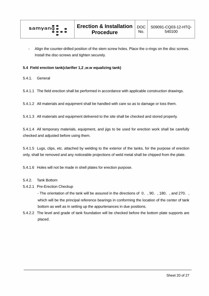
5.4.2.1 Pre-Erection Checkup
- The orientation of the tank will be assured in the directions of 0。, 90。, 180。, and 270。,
which will be the principal reference bearings in conforming the location of the center of tank
bottom as well as in setting up the appurtenances in due positions.
5.4.2.2 The level and grade of tank foundation will be checked before the bottom plate supports are
placed.
Erection & Installation Procedure
DOC No.
S09091-CQ03-12-HTQ-540100
Sheet 21 of 27
5.4.3 Bottom Plates
5.4.3.1 A bottom center plate will be laid on the center point which had been marked crosswise
above the foundation as shown in Fig. 1.
5.4.3.2 Bottom plates will be placed and arranged from center to outward such that the configuration
of the plates shall be identical to that shown in the relevant drawings.
5.4.3.3 Bottom plates will be assembled and tack-welded using special jigs for anti-distortion, if
necessary.
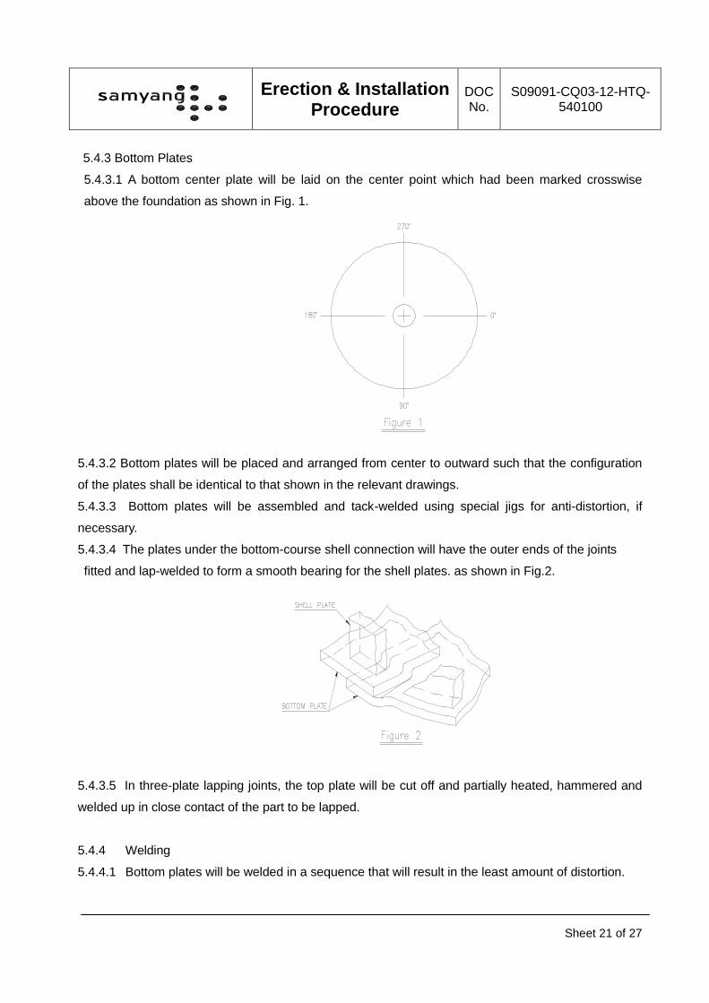
5.4.3.4 The plates under the bottom-course shell connection will have the outer ends of the joints
fitted and lap-welded to form a smooth bearing for the shell plates. as shown in Fig.2.
5.4.3.5 In three-plate lapping joints, the top plate will be cut off and partially heated, hammered and
welded up in close contact of the part to be lapped.
5.4.4 Welding
5.4.4.1 Bottom plates will be welded in a sequence that will result in the least amount of distortion.
Erection & Installation Procedure
DOC No.
S09091-CQ03-12-HTQ-540100
Sheet 22 of 27
At the continuous welding, transverse joints will be welded first. The welding will be started at the
center of plate width and proceeded outwards symmetrically.
When the transverse joints are welded welding of the longitudinal joints will be made from center
outwards in a same manner as the transverse joints.
5.4.4.2 Three-plate laps in tank bottom will not be closer than 305mm (12 in), from each other and
also from from the tank shell.
5.4.4.3 The fillet welding which fixes the bottom-course shell to the bottom plates, shall not be
started unless all the welding at least upto the third shell course welding has been completed.
- Shell-to-bottom continuous fillet welding will be laid on each side of the shell plate.
- The size of each weld will not be greater than 1/2in. (12.7mm) and not less than the
nominal thickness of the thinner of the two plates joined.
5.4.4. Shell Plates
5.4.4.1 Bottom-Course Shell Plates (temporary assembly)
- The shell circle line for erection will be drawn on the bottom plates and punched equally
according to the numbers of shell plates as a reference point.
- The location of the points which divide the circle will be determined such that the orientation
of all the appurtenances will be in conformity with the specification and/or drawings.
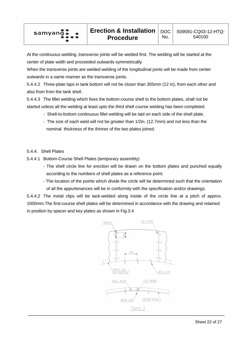
5.4.4.2 The metal clips will be tack-welded along inside of the circle line at a pitch of approx.
1000mm.The first-course shell plates will be determined in accordance with the drawing and retained
in position by spacer and key plates as shown in Fig.3.4
Erection & Installation Procedure
DOC No.
S09091-CQ03-12-HTQ-540100
Sheet 23 of 27
5.4.4.3 Before the erection of the shell plates, the reference point for fitting and the jig point will be
correctly marked on the inside of the shell plates.
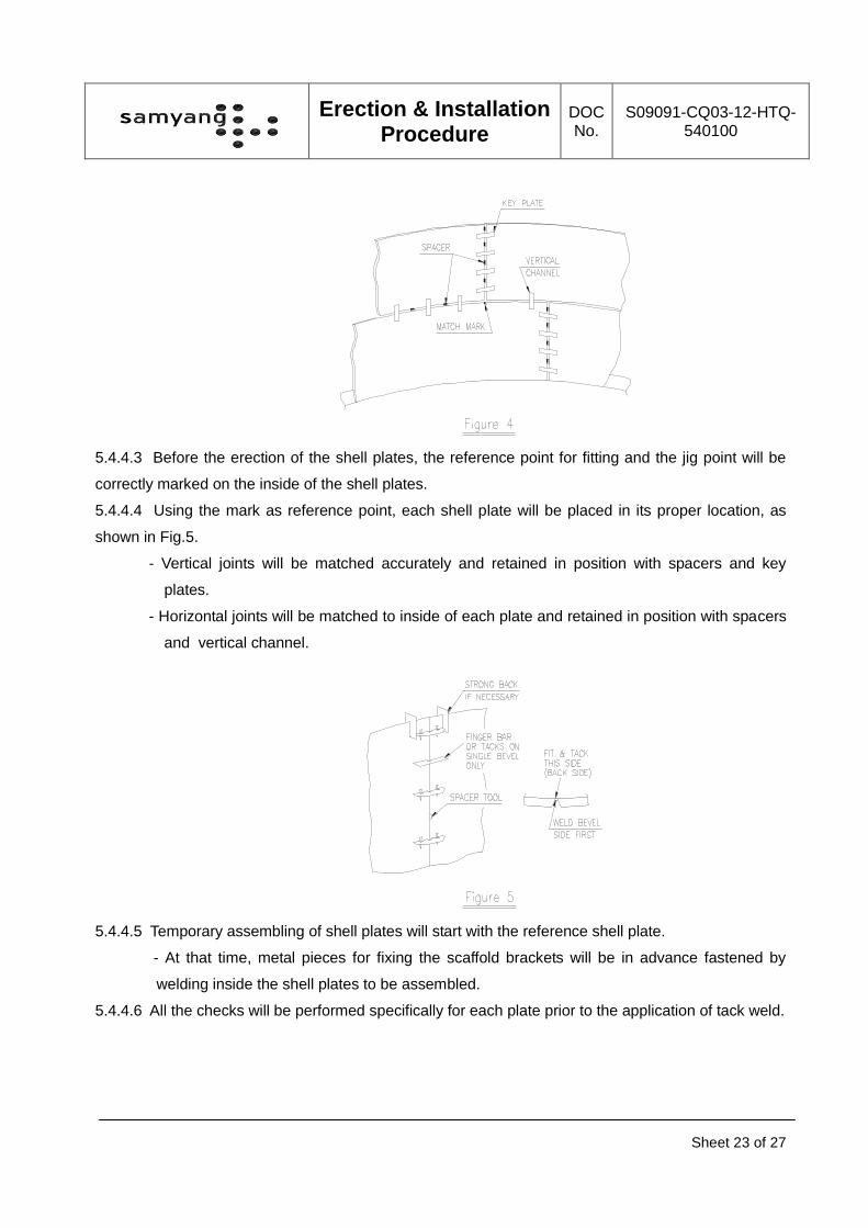
5.4.4.4 Using the mark as reference point, each shell plate will be placed in its proper location, as
shown in Fig.5.
- Vertical joints will be matched accurately and retained in position with spacers and key
plates.
- Horizontal joints will be matched to inside of each plate and retained in position with spacers
and vertical channel.
5.4.4.5 Temporary assembling of shell plates will start with the reference shell plate.
- At that time, metal pieces for fixing the scaffold brackets will be in advance fastened by
welding inside the shell plates to be assembled.
5.4.4.6 All the checks will be performed specifically for each plate prior to the application of tack weld.
Erection & Installation Procedure
DOC No.
S09091-CQ03-12-HTQ-540100
Sheet 24 of 27
5.4.5 The Second-Course Shell Plates (temporary assembly)
Second shell plates shall be temporarily assembled by aligning their vertical joints to the match
marks which are indicated on the inside of the bottom-course shell plates.
5.4.6 Welding of vertical joints of the first course
5.4.6.1 Vertical joints of the bottom course will be tack-welded from the inside and key plates and
shim plates will be removed and replaced by finger-bar.
5.4.6.2 The continuous welding will be made on the outside first.
5.4.6.3 Prior to the application of the first layer to the inside welding, the finger-bar will be removed
and welded joints will be cleaned thoroughly in a manner that will leave the exposed surface
satisfactory for fusion of the weld metal to be added. This cleaning will be made on the inside by air
gouging or grinding to evenly and smoothly.
5.4.7 Welding of vertical joints of the second course will be made in the same manner as the bottom
course.
5.4.8 Welding of horizontal joints between the first and second course
5.4.8.1 Automatic welding will be applied in horizontal joints of shell.
5.4.8.2 Welding of horizontal joints between the bottom and second course will be made on the
outside first,and being the stiffeners removed.
- If there were some defects at 1st layer which will be hindrance to welding from the inside,
they will be removed by are air gouging from the inside. After that, the reverse side of
horizontal joints will be welded.
5.4.8.3 The continuous fillet welding between the bottom edges of the bottom course shell plates and
bottom plates will be made at any time after welding of vertical joints of 1st course completed.
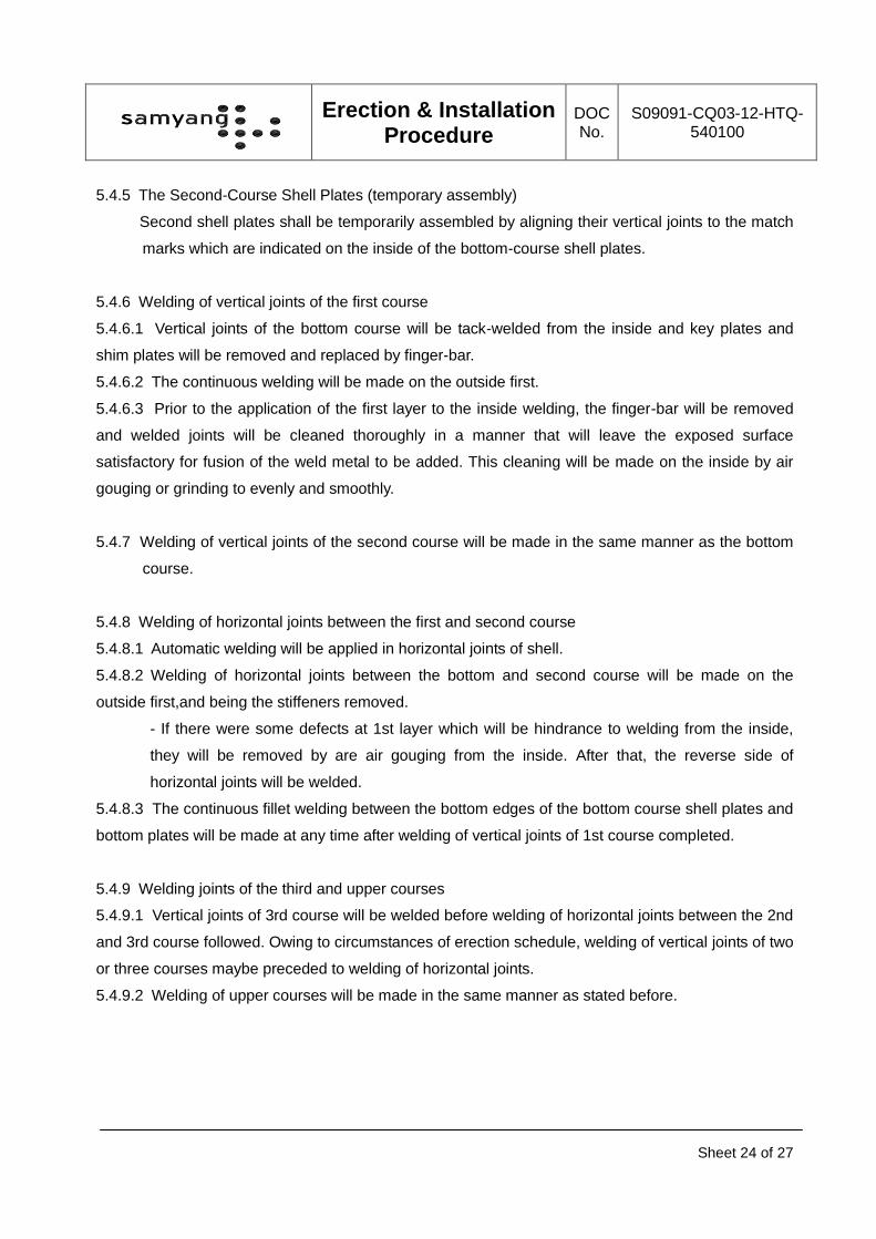
5.4.9 Welding joints of the third and upper courses
5.4.9.1 Vertical joints of 3rd course will be welded before welding of horizontal joints between the 2nd
and 3rd course followed. Owing to circumstances of erection schedule, welding of vertical joints of two
or three courses maybe preceded to welding of horizontal joints.
5.4.9.2 Welding of upper courses will be made in the same manner as stated before.
Erection & Installation Procedure
DOC No.
S09091-CQ03-12-HTQ-540100
Sheet 25 of 27
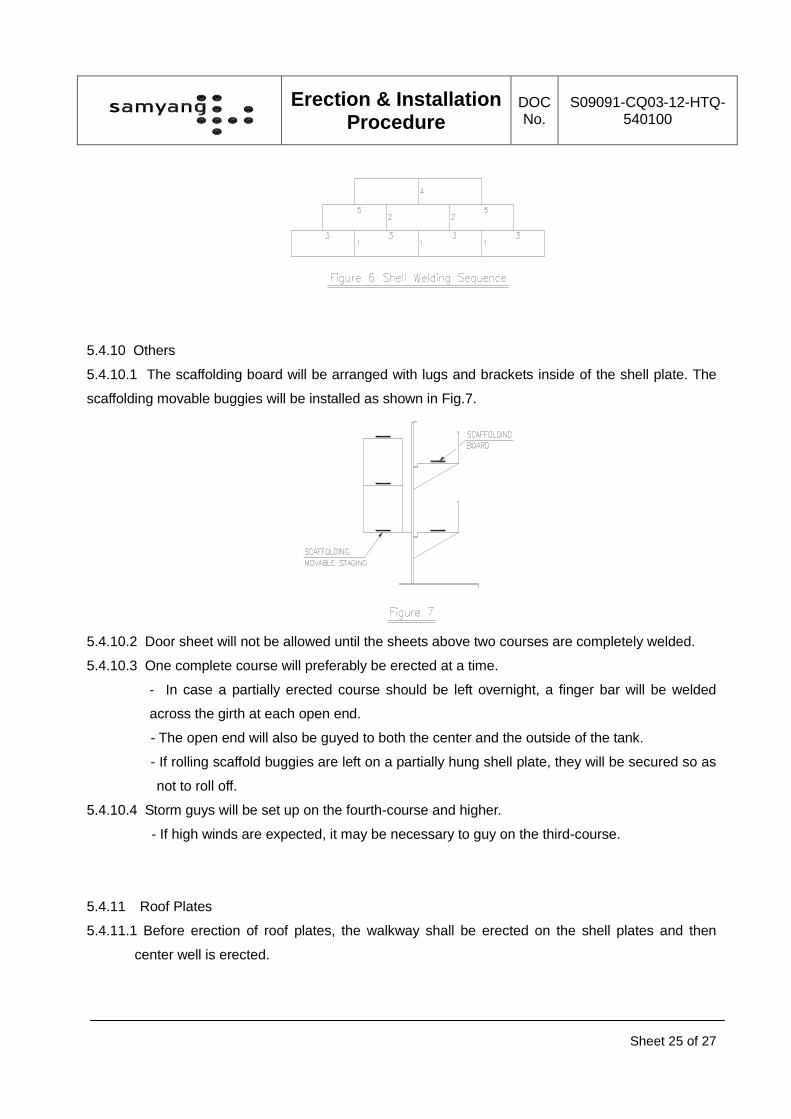
5.4.10 Others
5.4.10.1 The scaffolding board will be arranged with lugs and brackets inside of the shell plate. The
scaffolding movable buggies will be installed as shown in Fig.7.
5.4.10.2 Door sheet will not be allowed until the sheets above two courses are completely welded.
5.4.10.3 One complete course will preferably be erected at a time.
- In case a partially erected course should be left overnight, a finger bar will be welded
across the girth at each open end.
- The open end will also be guyed to both the center and the outside of the tank.
- If rolling scaffold buggies are left on a partially hung shell plate, they will be secured so as
not to roll off.
5.4.10.4 Storm guys will be set up on the fourth-course and higher.
- If high winds are expected, it may be necessary to guy on the third-course.
5.4.11 Roof Plates
5.4.11.1 Before erection of roof plates, the walkway shall be erected on the shell plates and then
center well is erected.
Erection & Installation Procedure
DOC No.
S09091-CQ03-12-HTQ-540100
Sheet 26 of 27
5.4.11.2 Scrapper & shaft etc. shall be installed prior to erection of roof.
5.4.11.3 Roof plate will be assembled in accordance with the drawings after all shell plates and top
angles welded completely.
5.4.11.4 Roof plates will be assembled and tack-welded using special jigs for anti-distortion if
necessary. Tack welds will not be less than 25mm long on about 500mm pitch.
5.5 Drive unit & Agitator.
5.5.1 Ensure the mounting location holes on mating surfaces match dimensions and orientation on
the drive unit & agitator drawing.
5.5.2 Position the drive on mounting surface by crane or lift. Bolt up rake cage to the drive or shaft.
Shim the drive so one rake will run in plane with the tank floor. Running drive “out of plane”
will not hurt the drive, but may cause damage to the rake mechanism. Fill all the gaps with
shims, and tighten the drive to mounting surface.
5.5.3 Fill all the gearboxes with oil as recommended in this manual.
5.5.4 Observe the rake mechanism for smoothness of operation. Any irregular motions, springing
action and binding or rubbing must be adjusted out of the rake assembly before placing the
clarifier in service.
5.5.5 After installation is complete, touch up any spots on drive or mechanism where the coating
has been scratched or rubbed off.
5.6 Providing of Supports
Pipe supports provided by contractor will be prefabricated with divided into parts at supplier’s shop.
The prefabricated parts shall be assembled and erected in accordance with the related drawings
during site erection. Cable tray supports shall be manufactured and erected on site before or during
erection periods. Refer to “Piping Support Plan Detail Drawing & Cable Raceway Plan & Detail.”
5.7 Adjustments
General erection & installation tolerance in distance between the vessels or tanks and the adjacent
equipment as well as in elevation of each vessel or tank is +5, - 0 mm.
Erection & Installation Procedure
DOC No.
S09091-CQ03-12-HTQ-540100
Sheet 27 of 27
5.8 Painting
- The painting system is in accordance with “Painting Specification and Procedure”.
- The site erection & installation contractor will process all technical data sheet given by supplier.
- All equipment are delivered with final paint but eventual scratches will be repainted after
completion of erection & installation.
5.9 The works after erection & installation
- Check of mechanical completion.