Embed Size (px)
Citation preview

THE ISRAEL ELECTRIC CORPORATION LIMITED
CENTRAL METERING UNIT
Specification No. 307-4-15
SINGLE-PHASE STATIC WHOLE CURRENT ELECTRICITY METERS
FOR ACTIVE ENERGY
I.E.Co Catalog No. 4453502
Name Signature Date
Prepared by: E. Feinstein
Data exchange advisor: E. Abramovich
Metrology policy: N. Calamaro
Approved by: I. Gueta
Approved by: M. Levy
Page 2 of 52 SPECIFICATION
307-4-15
Israel Electric Corp.
Central Metering Unit
TABLE OF CONTENTS
1. PURCHASER
2. NAME OF ITEM & PROJECT
3. LOCATION OF ITEM / PROJECT
4. SCOPE OF WORK
4.1 SCOPE OF SUPPLY / SERVICE
5. TERMINAL POINTS & TERMINAL CONNECTION
6. CYBER & INFORMATION SECURITY
7. QUALITY MANAGEMENT & QUALITY CONTROL
7.1 GENERAL QUALITY REQUIREMENTS
7.2 INTERCHANGEABILITY
8. STANDARDS & CODES
9. TECHNICAL DOCUMENTATION
9.1 GENERAL
9.2 TECHNICAL DOCUMENTS TO ACCOMPANY THE PROPOSAL
9.3 TECHNICAL DOCUMENTS AFTER NOTIFICATION OF AWARD
10. TECHNICAL REQUIREMENTS
10.1 ENVIROMENTAL CONSIDERATIONS & SERVICE CONDITIONS
10.2 RELIABILITY, AVAILABILITY, MAINTAINABILITY (RAM)
10.3 FUNCTIONAL REQUIREMENTS
10.4 PROPERTIES
10.5 DESIGN & CONSTRUCTION
10.6 COMMISSIONING
10.7 OPERATION & MAINTANANCE
Page 3 of 52 SPECIFICATION
307-4-15
Israel Electric Corp.
Central Metering Unit
10.7.1 GENERAL
10.7.2 SPARE & RENEWAL PARTS
11. TESTS & INSPECTIONS
12. PACKAGING & DELIVERY
13. STORAGE & HANDLING
14. NAMEPLATE / MARKING
15. NOTES
16. SPECIAL REQUIREMENTS
Appendix 1 – Shaped Screw Head for the Terminal Cover
Appendix 2 – Protective Sleeve for the Terminal Cover Screw
Appendix 3 – Nameplate Format
Appendix 4 – Official Logo of the Israel Electric Corp.
Appendix 5 – Company Symbol
Appendix 6 – Stranded Steel Wire for Sealing
Appendix 7 – Sealing
Appendix 8 – Pallet
Appendix 9 – Off the Shelf Product Requirements
Appendix 10 – Conformity with Bid Requirements Questionnaire
Appendix 11 – Manufacturer’s Qualification Questionnaire
Appendix 12 – Glossary
Page 4 of 52 SPECIFICATION
307-4-15
Israel Electric Corp.
Central Metering Unit
1. PURCHASER
The Israel Electric Corporation Limited (I.E.Co)
2. NAME OF ITEM & PROJECT
Single-Phase Static Whole Current Electricity Meter for Active Energy.
3. LOCATION OF ITEM / PROJECT
The specification refers to static active energy meters, with direct connection for single-phase
2-wire service.
4. SCOPE OF WORK
Single-Phase Static Whole Current Electricity Meters for Active Energy, Laboratory software,
Laptop software, HHU software. The manufacturer shall supply the communication protocol
reference data and manual. Also the software sources for the PC and HHU, subject to confidential
(Non Disclosure) agreements.
4.1 SCOPE OF SUPPLY / SERVICE
4.1.1 HHU / Portable PC / Lab PC Applications
a. The different applications shall run by different parameters (routine/function running with
different parameters, excluding the lab PC software).
b. HHU and portable PC shall use the same software (EXE, DLL, etc).
c. Portable software (portable - doesn't require installation) distribution should be by "copy and
paste" method, not installation and registration.
d. The software baud rate fixed/variable baud-rate will be according to the application, meter port
usage, and connections.
e. The software baud rate fixed /variable baud-rate is according application and meter port usages
and Connections. Meaning: 1200 bps1, 9600 bps
f. All software/licenses will be without time limitations.
Level Performed by Activities
0
Operator (meter
reader) with HHU
a
Meter reading. Automatic downloading and uploading
of data as follows:
b Enable copying of any file (configuration) from the
HHU to PC.
c Capable of identification of the meter model.
d Capable of identification of meter S.N.
e Capable of reading standard IECo data file (4.1.4).
1 BPS – Bits Per Second
Page 5 of 52 SPECIFICATION
307-4-15
Israel Electric Corp.
Central Metering Unit
f Capable of being embedded at an IECo wrapping
software through an executable command line, or
through an API. Control of software through that
interface should be of all required parameters.
1
Technician (meter
installer/
maintainer)
with portable PC
a
b
All the activities of Level 0
Dial Test mode (=ability to modify: enlarge/decrement,
meter's display resolution by 2-3 last decimal digits)
2
Technician/
Engineer with
Laboratory PC
a
b
All the activities of Level 0, 1
Same requirements as HHU.
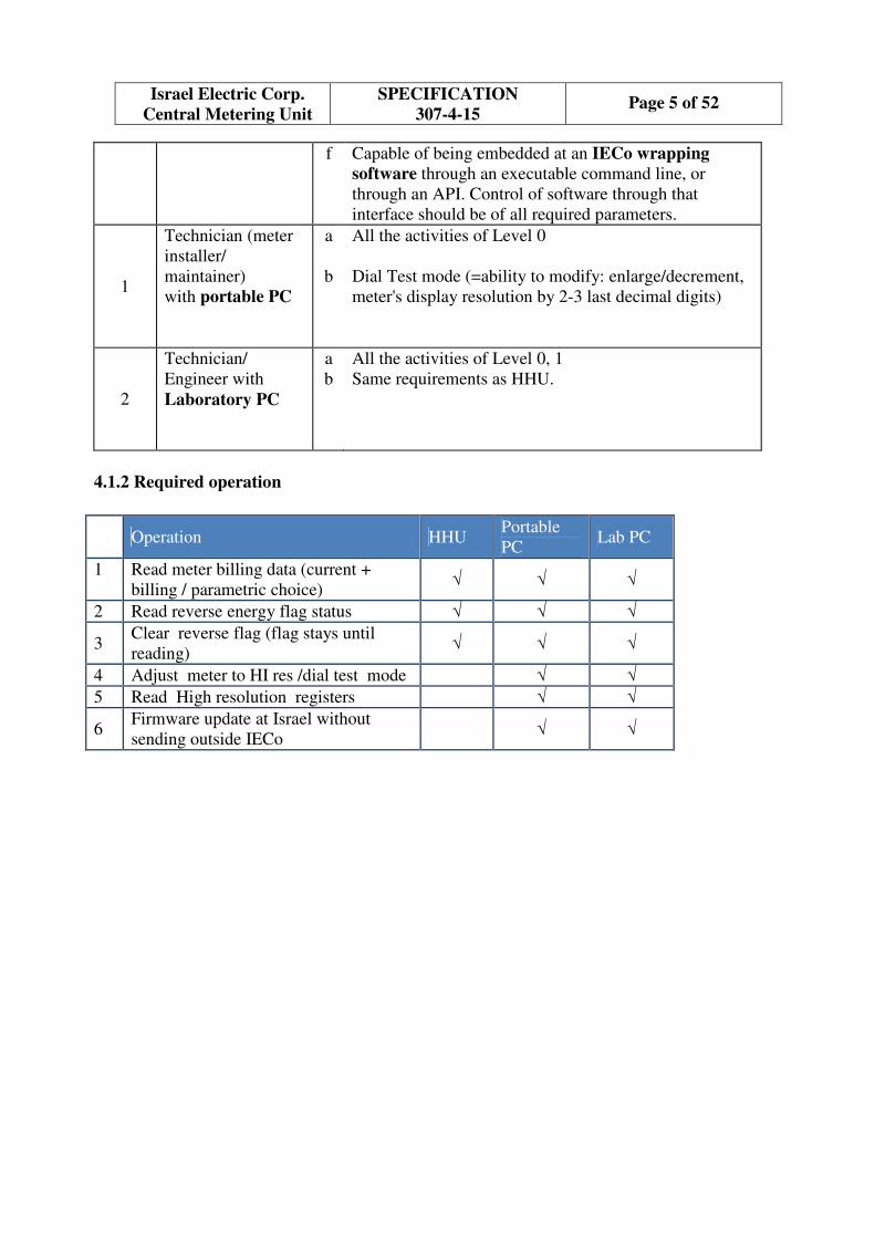
4.1.2 Required operation
Operation HHU
Portable
PC Lab PC
1
Read meter billing data (current +
billing / parametric choice) √ √ √
2 Read reverse energy flag status √ √ √
3 Clear reverse flag (flag stays until
reading) √ √ √
4 Adjust meter to HI res /dial test mode √ √
5 Read High resolution registers √ √
6 Firmware update at Israel without
sending outside IECo √ √

Page 6 of 52 SPECIFICATION
307-4-15
Israel Electric Corp.
Central Metering Unit
Figure 2: MC 65 HHU
4.1.3 Software and Routines / Data Flow and Process
System Computing Hardware and OS
a. The Manufacturer shall provide the software and all other means required for data exchange
between the Meter and the HHU/portable PC/Lab PC via the different communications.
b. System hardware and OS (operating system)
b.1. HHU type: Motorola MC 65 Rugged software configurable dual 3.5G WAN
Enterprise Digital Assistant (EDA).
Operating system: Microsoft® Windows Mobile® 6.5 Professional.
COM port: USB2 powering cradle for charging HHU and for interfacing with PC.
Keypad Options : Alpha/Numeric
b.2. Portable PC:
Operating system: Win 7.
COM port: USB2
b.3. Lab PC:
Operating system: Win 7.

Page 7 of 52 SPECIFICATION
307-4-15
Israel Electric Corp.
Central Metering Unit
COM port: regular serial com port, USB2.
c. In case of third party software, the manufacturer shall provide the software license needed from
the software developer. At the case that the third party software is the entire software's upper
layer, it should be capable of being embedded at an I.E.Co wrapping software through an
executable command line, or through an API. Control of software through that interface should
be of all required parameters. The latter should abide to both HHU and portable/Lab PC.
The HHU software is mandatory limited to a volume of around 2Mbytes.
Note:
In order to minimize SW integrations faults between the HHU and I.E.Co and Bidder SW
the Bidder should develop the HHU SW on the same HHU as I.E.Co .
I.E.Co will provide the HMI SW (only) to run this SW.
d. Software license – all software licenses (manufacture and third party) should be for unlimited
time duration.
Data Files and Auxiliary Management / Control Files Requirements
e. Meter data output files
e.1. There are three data files read out from the meter.
e.2. Limited technical data and events log file – I.E.Co format
e.3. Full technical data and events log file – manufacturer's format
e.4. The data files, output of the HHU/PC software, shall be ASCII files
e.5. The HHU and the PC data output meter files shall have the same data file structure
e.6. File and Record Formats data files shall include all the data available in the system, and the
Purchaser shall select the relevant data from these files.
f. Communication / Data Conversion / Software reports results Error File
f.1. During/after running the software an error file should be created.
f.2. The report result is for I.E.Co management of software usage.
f.3. The Error File output of the software, will be 3 bytes long (leading zero format), containing
results codes of operation.
f.4. If the communication / data conversion ends with no error, the ERR.DAT file will contain
the value 000, else the error code meter files shall be provided in ASCII format.
Page 8 of 52 SPECIFICATION
307-4-15
Israel Electric Corp.
Central Metering Unit
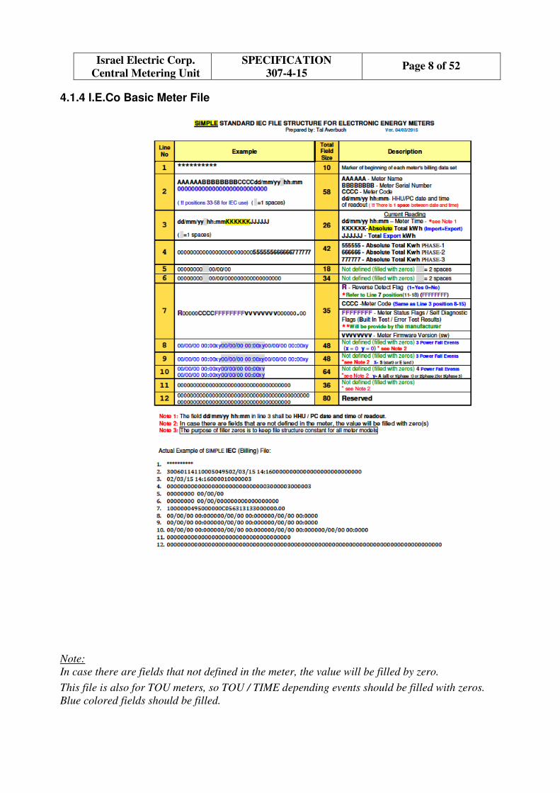
4.1.4 I.E.Co Basic Meter File
Note:
In case there are fields that not defined in the meter, the value will be filled by zero.
This file is also for TOU meters, so TOU / TIME depending events should be filled with zeros.
Blue colored fields should be filled.

Page 9 of 52 SPECIFICATION
307-4-15
Israel Electric Corp.
Central Metering Unit
5. TERMINAL POINTS & TERMINAL CONNECTION
5.1 HHU compatibility
The meter shall be able to communicate with I.E.Co standard HHU (MOTOROLA) via the optical
port and an adapter cable. See 4.1.1, 5.2
5.2 Local Communication Port
The meter shall have a local communication port, as follows.
5.2.1 An optically isolated connector, physically conforming to IEC62056-21 (2002) which shall
be installed on the front panel of the Meter and shall be immediately accessible (there shall
be no need to remove a cover for access).
5.2.2 The optical port should work with I.E.Co (REALLIN) optical probe, BLUSKY optical
probe as well as with ABACUS probe.
Figure 1 bellow shows these probes.
5.2.3 Data baud rate: 300 - 9600 bit /sec. A complete specification of manufacturer sign on rate and
general rate during all of its protocols, and dependent on hardware – is required.
A - Abacus probe B- REALLIN I.E.Co probe C - BLUSKY HHU probe
Figure 1: Images of optical probes
Important notes to the meter manufacturer:
The manufacturer should be aware that the meter must work with ABACUS, BLUSKY and
REALLIN optical probes. The manufacturer should be aware of the following notes for adaptation
of his meter to I.E.Co comm. requirements:
Probe type Requires/does not
require supply &
control signals
Connection
meter to HHU
Direct/indirect
Supported HW
protocol standard
Meter to Lab PC/laptop
Direct/indirect
connection
ABACUS Not required Direct IEC 62056-21
(previously 1107) Direct USB
REALLIN Not required Direct IEC 62056-21
(previously 1107) Direct USB
BLUSKY Not required Direct IEC 62056-21
(previously 1107) Direct USB

Page 10 of 52 SPECIFICATION
307-4-15
Israel Electric Corp.
Central Metering Unit
5.2.4 Communication Protocol Sources/Manuals
The manufacturer shall supply the communication protocol reference data and manual. Also the
software sources for the PC and HHU, subject to confidential (Non Disclosure) agreements.
I.E.Co request for information: regarding to comm. protocol software layer, that is dressed on top
of the HW interface (IEC 1107). Every manufacturer implements a protocol specified by data
packets, control words, the amount of data fetched by a single transaction, etc. During the tender,
the meter manufacturer should specify to I.E.Co to which of the following categories does the
protocol abide:
SW protocol layer standardization category
International comm. standard
Joint collaboration of several companies
Private company intellectual property
Data Readings Time Limitation
Current
Local (HHU/PC) 30 sec
Notes:
Data reading – Total kWh, Status Flag
Local HHU/PC to meter baud rate: 9600 bit/s
The time does not include connection time.

Page 11 of 52 SPECIFICATION
307-4-15
Israel Electric Corp.
Central Metering Unit
6. CYBER & INFORMATION SECURITY
n/a
7. QUALITY MANAGEMENT & QUALITY CONTROL
The Manufacturer’s Quality Management Program shall meet the requirements described in ISO
9001 (2008).
7.1 GENERAL QUALITY REQUIREMENTS
7.1.1 The Israel Electric Co. shall have the right to audit and comment on Manufacturer’s Quality
Management System, regardless of whether it was previously audited by a certifying agency
or any other body.
I.E.Co experts may ask to visit the manufacturer's plant at the technical stage of proposal
evaluation or later.
7.1.2 The Contractor shall submit under this paragraph his QM Manual and procedures for:
• Calibration (including explanation of calibration chains for main measurements that make
conditions to quality of final product).
• Qualification of suppliers.
• Non conformities and corrective actions.
7.1.3 Quality Control (QC)
The Manufacture shall submit with his proposal a preliminary Inspection and Test (I&T) Plan.
A mutually agreed inspection point plan, including witnesses and points, shall be agreed between
I.E.Co and the Manufacturer. Any subsequent alteration to this program shall require I.E.Co
agreement, prior to start of any work affected by these alternations.
Test and Inspection certificates as required in the specification and the applicable standards, shall be
submitted immediately following their generation. The certificates shall be original, signed by the
manufacturer, and contain actual measured values.
The generation of certificates, indulging those generated by subcontractors and sub-suppliers shall
bear no extra cost to the Israel Electric Co.
Any equipment non-conformance to drawings, specifications or any other purchase order
requirements which are considered by the manufacturer as “acceptable as it is” or “for repair”, shall
be submitted to the Israel Electric Co. for approval, with their recommended dispositions. All such
non-conformances shall be approved by the Israel Electric Co., shall be documented, and a copy of
the approval shall accompany each shipment.
All materials used in manufacturing the equipment shall conform to specifications, approved
drawings, and accepted Standards.
7.1.4 Manufacturing Experience and Capacity
The Bidder shall declare his experience in manufacturing meters identical to the proposed or of
similar type (see the definition of "similar type" in Preliminary Conditions). Bidder with experience
of less than two years will not be acceptable. More experienced bidder will have privilege (refer
Score Matrix, section 16, clause 9).
The Bidder shall declare his monthly capacity for manufacturing and calibrating the specific meter
type, while fulfilling all requirements for Quality Management, and without any degradation in
product quality (see MQQ - Appendix 11 - 3.3.4).

Page 12 of 52 SPECIFICATION
307-4-15
Israel Electric Corp.
Central Metering Unit
In case that the required monthly delivery quantity exceeds the manufacturer's declared capacity the
manufacturer shall provide proof on how he intends to deliver the order in time while meeting all
quality requirements.
Note: If, as a result of technological innovations, the manufacturing capacity is increased, an
I.E.Co representative will have the right to inspect and approve the new manufacturing processes
when they come on line.
7.2 INTERCHANGEABILITY
n/a
8. STANDARDS & CODES
The electricity meters proposed by the Bidder must fully comply with international standards
IEC62052-11 and IEC62053-21, or EN62052-11 and EN62053-21, or EN50470-1 and EN50470-3.
To show conformance with this requirement the bidder must provide a copy of a certificate of type
(pattern) approval from an authorized body or, in case of MID certified meter, valid Notified Body
as published by European Commission, confirming that the meter type, identical with the proposed
one, complies with the requirements of IEC62052-11 and IEC62053-21, or EN62052-11 and
EN62053-21, or EN50470-1 and EN50470-3 as per section 9.2.1 of the Spec 307-4-15.
8.1 LIST OF RELEVANT PUBLICATIONS
1. IEC62058-11 (2008) Electricity metering equipment - Acceptance testing – Common
requirements
2. IEC62058-31 (2008) Electricity metering equipment (AC) – Acceptance inspection –
Particular requirements for static meters for active energy (classes 0,2 S, 0,5 S, 1 and 2)
3. IEC62052-11 (2003) / EN62052-11
Electricity metering equipment (a.c.) – General requirements, tests and test conditions – Part
11: Metering equipment
4. IEC62053-21 (2003) / EN62053-21
Electricity metering equipment (a.c.) – Particular requirements – Part 21: Static meters for
active energy (classes 1 and 2)
5. IEC62056-21 (2002)
Electricity metering – Data exchange for meter reading, tariff and load control – Part 21:
Direct local data exchange
6. IEC60605 (1994)
Equipment Reliability Testing – Compliance test plans for failure rate and mean time between
failures assuming constant failure rate
7. IEC60300-3-2 (1993)
Dependability management – Part 3: Application guide – Section 2: Collection of
dependability data from the field
8. IEC62059-21 (2002)
Electricity metering equipment – Dependability – Part 21: Collection of meter dependability
data from the field

Page 13 of 52 SPECIFICATION
307-4-15
Israel Electric Corp.
Central Metering Unit
9. IEC60068-2-31 (2008)
Environmental testing - Tests – Test Ec: Rough handling shocks, primarily for equipment-
type specimens
10. IEC60529 (2001)
Degree of protection provided by enclosures (IP Code)
11. BS7856:1996
Code of practice for design of alternating current, watt-hour meters for active energy (classes
1 and 2)
12. EN 50470-1
Electricity metering equipment (a.c.) – General requirements, tests and test conditions – Part
1: Metering equipment (class indexes A, B and C).
13. EN 50470-3
Electricity metering equipment (a.c.) – Particular requirements – Part 3: Static meters for
active energy (class indexes A, B and C).
14. 62059-31-1
Accelerated reliability testing – Elevated temperature and humidity.
9. TECHNICAL DOCUMENTATION
9.1 GENERAL
All applicable documents shall be in English, and shall refer to the specific plant where the
proposed meters are manufactured.
9.2 TECHNICAL DOCUMENTS TO ACCOMPANY THE PROPOSAL
9.2.1 A true copy of a certificate of type (pattern) approval from an authorized body (institute,
laboratory or competent organization), confirming that the meter type, identical with the
proposed one, complies with the requirements of IEC62052-11 and IEC62053-21 or
EN62052-11 and EN62053-21, or EN50470-3.
The certificate must include complete test results according to all requirements of the above
standards, or the test results shall be supplied separately, performed by an ISO 17025
accredited laboratory such as PTB, OFGEM, KEMA, NMI, METAS, etc. or by valid
Notified Body listed by NANDO:
(http://ec.europa.eu/enterprise/newapproach/nando/index.cfm?fuseaction=search.notifiedbo
dy)
If the tests are performed in a laboratory other than those listed above, the laboratory must
be internationally accredited to ISO17025 and provide proof that its Scope of Activity
includes meter testing and certification. A true copy of the laboratory accreditation
certificate must be enclosed.
If it is not possible to receive the test results officially printed, the bidder shall provide
results of the same tests, carried out in another accredited laboratory but traceable to the
National Laboratory and also approval certificate, issued by the Authorized institute, that the
meters comply with the standard.

Page 14 of 52 SPECIFICATION
307-4-15
Israel Electric Corp.
Central Metering Unit
The Bidder shall provide full details of modifications – if any – made to the offered meter
since it was submitted for type test approval.
9.2.2 A copy of a certificate of compliance with ISO9001 (2008) issued by a Certification Body
(CB) which is a qualified by an Accreditation Body (AB).
9.2.3 A list of utilities, which have purchased electricity meters of a similar type and of the same
manufacture, proposed in the bid, during a period of three years, just preceding the last date
for submission of technical proposals. Such list shall include the dates of sale, the quantities
sold and the name of person to whom I.E.Co may contact for clarifications at these utilities.
The dates and quantities must be proved by the customers' reference letters provided with
the offer.
9.2.4 Filled copy of Manufacturer's Qualification Questionnaire (Ap. 11).
9.2.5 Filled copy of the RAM Questionnaire (section 10.2).
9.2.6 Manufacturer Quality Management Manual.
9.2.7 Filled copy of Conformity with requirements questionnaire.
9.2.8 A list as well as Calibration certificates and traceability charts for all relevant test and
calibration equipment including equipment for initial calibration.
9.2.9 The manufacturer shall attach with the technical offer a complete description of the meter
with all its properties and its detailed relation to each item of this specification.
9.2.10 The manufacturer shall fill in the Checklist of the Documents (See Appendix 10, T. 5).
The manufacturer shall authorize his agreement to every item of this specification by signing.
9.3 TECHNICAL DOCUMENTS AFTER NOTIFICATION OF AWARD
Manufacturer shall submit for Purchaser’s approval, no later than four (4) weeks after award of
contract, the documents indicated below.
9.3.1 Functional Acceptance Tests (FAT) and Report
9.3.1.1 Foreword - objective
In order to let I.E.Co receive a meter with a high quality and smoother adaptation to I.E.Co
requirements a Functional Test Report (along with the meters calibration certificate and metrology
report) should be submitted by the manufacturer. The FAT submittal must be not later than at the
stage of the first trial meters submitting for the tests of the Spec. conformity conducted by I.E.Co
after the winners have been proclaimed.
9.3.1.2 Testing chapters
The following table defines the test chapters:
No. Basic test chapters Chapter contents, description
1 Software support package testing according to its
functions:
Reading data file
Communication
If the software is tested as a byproduct of the meter
testing, the manufacturer shall separately mark the
software test items.
Page 15 of 52 SPECIFICATION
307-4-15
Israel Electric Corp.
Central Metering Unit
2 I.E.Co standard file testing Section 4.1.4 – file spec
3 Registration of the status flags
testing
Verify functionality by simulation of the status bits.
4 HHU testing Test the full I.E.Co required capability with HHU
(sections 5.1, 5.2 )
5 Portable PC, Lab PC testing Horizontally test sections 1-3 above.
6 Miscellaneous Any test item that is not correlated with previous
chapters.
Example: file read during comm. sudden break.
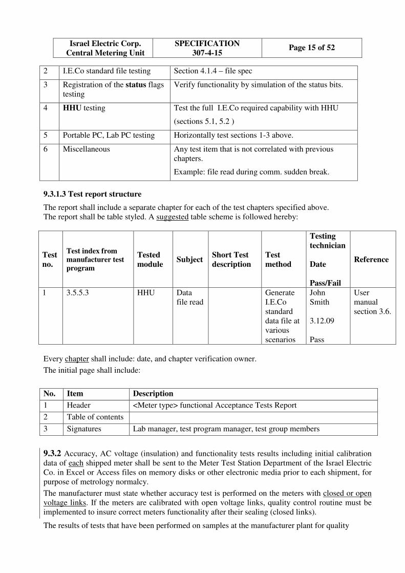
9.3.1.3 Test report structure
The report shall include a separate chapter for each of the test chapters specified above.
The report shall be table styled. A suggested table scheme is followed hereby:
Test
no.
Test index from
manufacturer test
program
Tested
module Subject
Short Test
description
Test
method
Testing
technician
Date
Pass/Fail
Reference
1 3.5.5.3 HHU Data
file read
Generate
I.E.Co
standard
data file at
various
scenarios
John
Smith
3.12.09
Pass
User
manual
section 3.6.
Every chapter shall include: date, and chapter verification owner.
The initial page shall include:
No. Item Description
1 Header <Meter type> functional Acceptance Tests Report
2 Table of contents
3 Signatures Lab manager, test program manager, test group members
9.3.2 Accuracy, AC voltage (insulation) and functionality tests results including initial calibration
data of each shipped meter shall be sent to the Meter Test Station Department of the Israel Electric
Co. in Excel or Access files on memory disks or other electronic media prior to each shipment, for
purpose of metrology normalcy.
The manufacturer must state whether accuracy test is performed on the meters with closed or open
voltage links. If the meters are calibrated with open voltage links, quality control routine must be
implemented to insure correct meters functionality after their sealing (closed links).
The results of tests that have been performed on samples at the manufacturer plant for quality

Page 16 of 52 SPECIFICATION
307-4-15
Israel Electric Corp.
Central Metering Unit
inspection purposes shall also be sent in the same format. Each shipped platform arrangement will
be announced and attached to the test report.
9.3.3 Calibration certificate of test equipment, on which calibration and final test of the meters are
performed, in accordance with IEC 60736, including traceability chain.
9.3.4 List of qualified suppliers of the most important parts and components (microprocessor,
metering IC, non-volatile memory, LCD, etc.).
10. TECHNICAL REQUIREMENTS
The Meter must have the following main features:
• Single rate (flat rate) active energy
• Reference voltage (Un): 230 V
• Basic current (Ib): 10 A or 5 A
• Maximum current (Imax): 60 A or more
• Reference frequency: 50 Hz
• Accuracy: Class 2 according to IEC62053-21 / EN62053-21 or Class index B according to
EN 50470-3
• Meter performance including memory will not require an internal battery or super-cap.
Note: Meters which are type approved to Class 1 accuracy will also be acceptable.
10.1 ENVIROMENTAL CONSIDERATIONS & SERVICE CONDITIONS
Meters shall be finished to keep all specified features when installed indoors in humid tropical
environment, and exposed to direct solar radiation.
In addition to mechanical tests described in IEC/EN 62052-11, the meter shall withstand the free
fall test prescribed in IEC60068-2-31.
10.2 RELIABILITY, AVAILABILITY, MAINTAINABILITY (RAM)
A1. Definitions
The definitions for RAM purposes in the Specification for electronic watt-hour meters as included
in IEC TR62059-11, IEC62059-21, IEC62059-41. The RAM parameters are characteristics of the
meter design and production only, when they are properly used and maintained.
The following notes will be taken to consideration:
1. Electronic Watt-hour Meters - SINGLE-PHASE STATIC WHOLE CURRENT
METERS FOR ACTIVE ENERGY
See items of Specification.
2. Maintenance
Maintenance is any action taken to:
• Replace a faulty meter with a properly working one, after a failure, and
• Test the operable condition of a replaced meter.

Page 17 of 52 SPECIFICATION
307-4-15
Israel Electric Corp.
Central Metering Unit
Note. Both these actions should conform meter replacement time (MRT).
A2. RAM Requirements
The Bidder is required to provide I.E.Co with meters with the following RAM properties:
1. Reliability
• MTTF (operating time to first failure): 20 years or more.
• Useful life: At least 16 years, without the need for maintenance or recalibration.
2. Maintainability
The RAM estimate based on free of “preventive maintenance” service. Corrective maintenance only
should applicable.
Note. Since I.E.Co approach to meter fault elimination is by means of valid replacement of a
damaged meter by another one (new or used, however tested as revised product) conducting by
appropriate billing, maintainability is converting to influence of definite meter type on mean time
of these replacement (MRT). The MRT shall not exceed 20 min for the same meter type replacement
by trained personnel.
A3. RAM Information
The Bidder shall submit to I.E.Co the following information regarding RAM:
1. RAM activities in his plant concerning the offered meter, and how he is organized to perform
these activities.
2. Supervising on his subcontractors, suppliers and vendors for their RAM activities.
3. The optimization shall consider the following:
• Criticality (long supply time, high price, short life length, high failure rate, single supply
source, sensitive or vulnerable materials, etc.
• Latent failure rate (λ), and induced failure rate (caused by human).
• Turn Around Time (door to door).
• Quantity in service.
• Recommended “probability of no shortage” (spares availability) on shelf.
• Cost.
A4. Bidder RAM Declaration
1. The Bidder shall state in Table A1 of the Annex AA attached to this document, the minimum
predicted MTTF, and the useful life length values of his offered meter, when operated within
their specified environmental extreme conditions, as per the Specification of the meter. The
sum rate λ and these components values as predicted and verified (tested) will be reflected at
MTTF state.
Note. The MTTF prediction shall be based on models, stress methods and reporting
mode as given by IEC62059-41.
2. The Bidder shall state also in Table A2 of the Annex AA, the RAM historical field data of his
offered meter.

Page 18 of 52 SPECIFICATION
307-4-15
Israel Electric Corp.
Central Metering Unit
The Bidder shall state the rationales for his above-mentioned declarations (usage/tests/
analysis/estimation).
A5. RAM Field Data
The data collection report shall be in categories of IEC62059-21.
A6. Reliability Demonstration
I.E.Co has the privilege to exercise a Reliability Field Demonstration (RFD) concerning the
supplied meter. The purpose of the RFD is to verify that the meters meet the reliability
requirement, i.e., MTTF of 20 years.
If subject to execution, the RFD will be conducted in accordance with the following principles:
1. The RFD shall be objective, quantitative and based on data collection from returned faulty
meters (see IEC60300-3-2 Application Guide, IEC62059-21).
2. The Contractor has nothing to do in the RFD, except to participate in the Failure Review Board
(FRB). However, the Contractor has to do his best in his plant in the following areas, in order
to supply to I.E.Co with reliable meters, and thus to pass the RFD with high probability:
• Design and Development.
• Parts, materials, and components.
• Manufacturing Processes.
• Quality Management and Control.
• Tests and inspections.
• Subcontractors, Suppliers, and Vendors supervision.
• Packaging, Handling, Storage, and Transportation (PHST).
3. The FRB is the only body entitled to classify failures as “Relevant”, or “Non-relevant” for the
purpose of the RFD.
4. The Contractor is responsible for productive agency of RFD results.
5. The RFD shall be ended with either ACCEPT, or REJECT result.
6. The meaning of REJECT result is violation of the specification, and the contract will deal with
such a situation.
7. The RFD will be framed in accordance with standard reliability test methods.
Note:. It is recommended to:
• Explore IEC60300-2, in order to show the dependability program of the offered meter.
• Explore IEC62059-11 and IEC62059-21, in order to demonstrate the dependability level
by means of internationally agreed procedures for dependability data collection.
However, if it will be agreed between I.E.Co and winner of the Contract, another equivalent
test plan could be chosen and published, as required by the relevant national body of the
country where the meter is manufactured.
8. The complete RFD plan, including demonstration parameters, will be prepared after contract
award, in consultation between I.E.Co Reliability, and Equipment Dept., and the contract
winner.
Page 19 of 52 SPECIFICATION
307-4-15
Israel Electric Corp.
Central Metering Unit
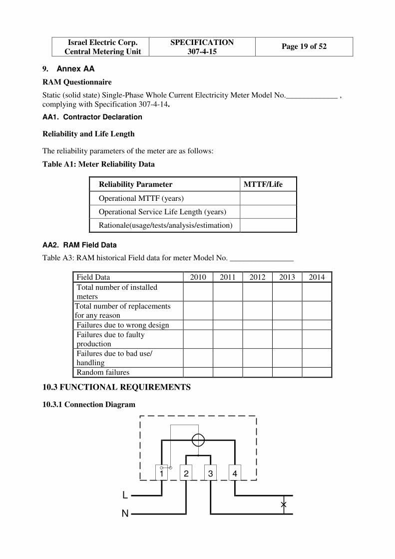
9. Annex AA
RAM Questionnaire
Static (solid state) Single-Phase Whole Current Electricity Meter Model No._____________ ,
complying with Specification 307-4-14.
AA1. Contractor Declaration
Reliability and Life Length
The reliability parameters of the meter are as follows:
Table A1: Meter Reliability Data
Reliability Parameter MTTF/Life
Operational MTTF (years)
Operational Service Life Length (years)
Rationale(usage/tests/analysis/estimation)
AA2. RAM Field Data
Table A3: RAM historical Field data for meter Model No. ________________
2014 2013 2012 2011 2010 Field Data
Total number of installed
meters
Total number of replacements
for any reason
Failures due to wrong design
Failures due to faulty
production
Failures due to bad use/
handling
Random failures
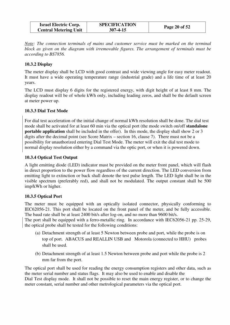
10.3 FUNCTIONAL REQUIREMENTS
10.3.1 Connection Diagram
3 41 2
L
N
Page 20 of 52 SPECIFICATION
307-4-15
Israel Electric Corp.
Central Metering Unit
Note: The connection terminals of mains and customer service must be marked on the terminal
block as given on the diagram with irremovable figures. The arrangement of terminals must be
according to BS7856.
10.3.2 Display
The meter display shall be LCD with good contrast and wide viewing angle for easy meter readout.
It must have a wide operating temperature range (industrial grade) and a life time of at least 20
years.
The LCD must display 6 digits for the registered energy, with digit height of at least 8 mm. The
display readout will be of whole kWh only, including leading zeros, and shall be the default screen
at meter power up.
10.3.3 Dial Test Mode
For dial test acceleration of the initial change of normal kWh resolution shall be done. The dial test
mode shall be activated for at least 60 min via the optical port (the mode switch on/off standalone
portable application shall be included in the offer). In this mode, the display shall show 2 or 3
digits after the decimal point (see Score Matrix – section 16, clause 7). There must not be a
possibility for unauthorized entering Dial Test Mode. The meter will exit the dial test mode to
normal display resolution either by a command via the optic port, or when it is powered down.
10.3.4 Optical Test Output
A light emitting diode (LED) indicator must be provided on the meter front panel, which will flash
in direct proportion to the power flow regardless of the current direction. The LED conversion from
emitting light to extinction or back shall denote the test pulse length. The LED light shall be in the
visible spectrum (preferably red), and shall not be modulated. The output constant shall be 500
imp/kWh or higher.
10.3.5 Optical Port
The meter must be equipped with an optically isolated connector, physically conforming to
IEC62056-21. This port shall be located on the front panel of the meter, and be fully accessible.
The baud rate shall be at least 2400 bit/s after log-on, and no more than 9600 bit/s.
The port shall be equipped with a ferro-metallic ring. In accordance with IEC62056-21 pp. 25-29,
the optical probe shall be tested for the following conditions:
(a) Detachment strength of at least 5 Newton between probe and port, while the probe is on
top of port. ABACUS and REALLIN USB and Motorola (connected to HHU) probes
shall be used.
(b) Detachment strength of at least 1.5 Newton between probe and port while the probe is 2
mm far from the port.
The optical port shall be used for reading the energy consumption registers and other data, such as
the meter serial number and status flags. It may also be used to enable and disable the
Dial Test display mode. It shall not be possible to reset the main energy register, or to change the
meter constant, serial number and other metrological parameters via the optical port.
Page 21 of 52 SPECIFICATION
307-4-15
Israel Electric Corp.
Central Metering Unit
10.3.6 Energy Registers
The meter shall measure and register energy irrespective of the direction of current flow. The
register will show the absolute active energy total kWh (OBIS 15.8.0). The content of this register
will be displayed, and also be readable via the optical port for billing purposes.
An additional energy register shall be provided – for diagnostics purposes – to record the negative
active energy total separately (OBIS 2.8.0).
The energy register data shall be backed up in a non-volatile memory (NVM) location, so that
during mains power failure energy readings are not lost or reset.
10.3.7 Excessive Magnetic Flux Protection
The meter shall be protected against external continuous magnetic flux levels which exceed the
value defined in IEC/EN62053-21, para. 8.2.4, as an influence factor. An external flux of up to 1.5
kG will not change the meter error by more than ± 2%.
The test conditions for protection level are as follows: an external source of 1.2-1.5 kG magnetic
flux will be placed as close as possible to any meter surface. Meter errors prior and after the
application of flux will be compared. The test load is Un, Ib, PF=1.
10.3.8 Status Flags for Diagnostics and Service Events
On power-up, the meter shall perform a self-test and produce an appropriate error code.
10.3.9 Status Register Reset
Status flags (reverse flow, magnet, error, etc.) shall be saved in the meter memory between
sequential meter readings. The flags shall be reset to their default state via the optical port as part of
the reading procedure (flags are shown in the read data), or as an initiated password protected
operation. The status flag data shall be saved in the non-volatile memory (NVM).
10.3.10 Meter Serial Number
The meter's unique serial number shall be recorded both as printed numbers and barcode, and also
recorded in permanent memory, and available for readout via the optical port. It must be impossible
to change or delete the serial number.
The barcode and the internal memory's serial number shall consist of 12 digits: the first 4 digits
shall present the meter code with leading zeroes if necessary, and the next 8 digits shall present the
unique serial number where the first two digits present the manufacture year. These 8 digits shall
form also the serial number imprint for visual reception (See section 14 and Appendix 3). The
figures of the imprinted serial number shall be of at least 4 mm height and 2 mm width.
10.3.11 Data Structure and Software
The manufacturer shall define the format of the energy registers, status register, diagnostics and
other data read via the optical port. The file structure and the relevant software for interfacing with
the HHU, etc. must be sent by the tender winner to I.E.Co along with the preliminary 5-meter series
(see section 16).
10.3.12 Rate Schedule
The meter shall be single rate (flat rate) type. There will be no need for a real time clock, calendar,
back-up battery, time-stamped log file, or any other real-time-related feature.

Page 22 of 52 SPECIFICATION
307-4-15
Israel Electric Corp.
Central Metering Unit
10.3.13 Over-voltage Protection
If a voltage of up to 400V is applied between the phase and neutral, the meter shall not be damaged,
and continue to operate properly when the over-voltage condition is removed.
Note: The thermal voltage (Uth) test conditions are as follows. The meter must run for two hours at
Uth, and immediately afterwards for two hours at Un. The meter error values before and after the
test will be compared. The test load is Un, Ib and PF=1.
10.3.14 Long-term Over-current (Thermal Current) Protection
Above and beyond the requirements specified in IEC/EN62053-21, the meter shall continuously
withstand a current of at least 120% Imax. The meter shall not be damaged, and continue to operate
properly when the over-current condition is removed.
Note: The thermal current (Ith) test conditions are as follows. The meter must run for two hours at
Ith, and immediately afterwards for two hours at Imax. The meter error values before and after the
test will be compared. The test load is Un, Imax and PF=1.
10.4 PROPERTIES
10.4.1 Dimensions
The meter dimensions shall not exceed those defined in BS7856:1996 publication
10.4.2 Mounting Holes
The mounting holes spacing shall be in accordance with BS7856:1996, Fig.1.
The top mounting hole (hanging point) is optional.
10.4.3 Weight
Weight: ≤ 1.5 kg.
10.5 DESIGN & CONSTRUCTION
10.5.1 Meter Case
The meter case shall be made of non-hygroscopic insulating material, self-extinguishing class V-2
according to IEC60695-11-10. It shall be insulating encased with protective class II according to
IEC/EN 62052-11, and sealed against penetration of dust and moisture (IP 51, per IEC60529). Its
shape shall be in accordance with BS7856:1996 (for single-phase).
The meter case, as a whole, shall withstand the spring hammer test with energy equal to
0.35 J.
10.5.2 Display Window
The display window shall be made of transparent, UV radiation resistant polycarbonate, or another
equivalent material. If a material other than polycarbonate is used, the Bidder is required to submit
a full description about its characteristics and evidence for its quality and durability.
Page 23 of 52 SPECIFICATION
307-4-15
Israel Electric Corp.
Central Metering Unit
10.5.3 Display Backlight
A backlight feature for the display is preferred. If provided, the display backlight shall be activated
by a front panel push button or any other freely accessible facility
10.5.4 Voltage Link
The input voltage connection (link), if any, shall be inside the meter case and shall not be accessible
while opening the cover of the terminal block.
Note: The meters will be supplied to I.E.Co with the link, if any, closed, and checked for continuity.
10.5.5 Sealing
The meter base and cover could be either ultrasonically welded or permanently glued together to
prevent access to internal components.
Alternatively, two screws securing the meter cover to the base should be either unidirectional, or be
featured by sheared head, so as to be irremovable when the meter is mounted in location.
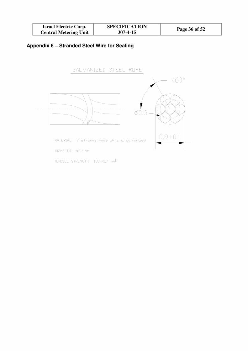
The seals shall be of the same type, made of tin-coated electrolyte copper and crimped on a
galvanized or stainless steel cable ("rope").
The seal should be fixed adjacent as much as possible to the screw which is sealed, and the surplus
cable ends should be cut off adjacent to the seal.
The measures must be taken to prevent user wounding from sharp seals rope edges.
If the meter is not welded or glued it should have tamper evidence sticker on both meter's sides.
Drawings of the sealing cable are attached (Appendix 5).
Drawings and details of the preferable and alternative seals are shown in Appendix 6.
The seal shall carry metrological marking that demonstrates the initial calibration performed on the
meter.
The manufacturer must submit a sample of the proposed seal for I.E.Co approval. Exactly the same
type of seal shall be used throughout the period of supply. Any further change in seal shape or
format must be notified to I.E.Co in advance and approved.
10.5.6 Terminal Block
The shape of the terminal block and its cover shall be in accordance with BS7856:1996 on the
assumption of meter features and performance.
10.5.6.1 Terminals
Each terminal must be provided with two screws to tighten copper conductor/thimble directly (so-
called "pillar-bar-type" terminal), or by means of lift-clip which pinches a conductor (so-called "lift-
type" terminal). "Pillar-bar-type" terminal is preferable. See Score Matrix - section 16, clause 4.
"Pillar-bar-type" terminal must be made of brass and be protected against corrosion. Ni plating (5
micron min) is preferable.
The pinching clip of "lift-type" terminal must be either made of Steel 8,8 and be Nickel plated, or
made of brass and be protected against corrosion. Ni plating (5 micron min) is preferable.
The terminals in their tightened position must allow steady bottom connection of the meter to
"quick springy connectors" of Test Benches for metrological tests.
There must not be access to internal parts of the meter through the terminals.
The bore diameter for external cable connection shall be at least 8.0 -0.22 mm in accordance with
Page 24 of 52 SPECIFICATION
307-4-15
Israel Electric Corp.
Central Metering Unit
ISO 286-1, 282-2 tolerances specifications.
10.5.6.2 Terminal Screws
The screw diameter must be at least M6. The screw bottom must be chamfered, without rough
edges. The pinching screws must be made either of Steel 8,8 and be Nickel plated (5 micron min),
or made of brass and be protected against corrosion. Nickel plating (5 micron min) is preferable.
See Score Matrix – section 16, clause 5.
In any case, there should no galvanic couple be set up between the screws, terminals and copper
conductor/thimble. Alloys potential difference must not exceed 0.15V (refer ASTM G82 Standard).
The meters must be supplied with all terminal screws fully inserted into the terminals, and tightened
enough to prevent being loosened due to vibrations during transportation.
Manufacturer is required to state the maximum allowed torque to be applied to the pinching screws.
10.5.6.3 Terminal Cover
The terminal cover shall be non-breakable, UV radiation resistant and self-extinguishing class V-2
according to IEC60695-11-10, or better.
The cover shall be extended type with free space of at least 40 mm for the connecting cables.
The cover shall be firmly attached to the case with one or two shaped-head screws in protective
sleeves (Appendix 2), which are an integral part of the cover.
The cover shall be packed for shipping unscrewed, together with the meter, while the
measures are taken to prevent the cover screws from "self-tightening" during transportation.
The shaped screws, however, shall be inserted into their places in the cover.
The shaped-head screw shall have a hole suitable for sealing of the terminal block with sealing wire
(Appendixes 1 and 2). The screw shall have M4x0.5 thread and be made of MS58 brass 10µm
nickel-plated. The shaped-head screw shall be protected from slip out from the sleeve when not
tightened.
After the meter is mounted, no access to the installation screws as well as terminals or cables shall
be possible without breaking the seal or the cover itself.
The connection diagram of the meter with terminals marking should be attached to or stamped on
the inner side of the cover.
10.5.7 Modification of the Meter Design and Technology
Any change in technology processes – including its replacement, modification of the meter form, its
components (including sub-supplier swap), structure of parts or materials from which the parts are
made of – after I.E.Co has approved the meter, shall be done only after written agreement with the
Israel Electric Co. has been settled. For obtaining this agreement the manufacturer shall present the
company with the following:
• The engineering drawings describing the modification.
• In case of components sub-supplier swap – batch QC data
• Samples to be tested in the Israel Electric Co. according to its judgment.
• Proof that the proposed modification does not reduce the quality or performance of the meter.
Note: In case the main manufacturing line is replaced by another, an I.E.Co representative will
inspect and approve the new premises before manufacturing will commence there.

Page 25 of 52 SPECIFICATION
307-4-15
Israel Electric Corp.
Central Metering Unit
If the said modifications result in degradation of meter performance or quality, I.E.Co reserves the
right to demand that the meters be returned to their original form.
If it has been agreed between the manufacturer and the I.E.Co to carry out the modification, the
manufacturer shall inform the company in writing about the serial number of the first modified
meter, and the batch or shipment identification details.
10.6 COMMISSIONING
10.6.1 Preproduction Series
The awarded bidder must send to the company the meters as preliminary (preproduction) series by
quantity of 5 meters for a Conformity of Compliance in 50 working days period after receiving the
order. The meters must be in their final version, manufactured or assembled in the same plant where
the remaining meters will be produced, tested with the same equipment that will be used in the
course of manufacturing, and packed in the same form that the future meters will be supplied. The 5
meters delivery must be accompanied by the data reading software, and the files described in
section 4.1.
After approval of these 5 meters the awarded bidder must send to the I.E.Co the meters as
preliminary (preproduction) series again, this time by quantity of one full pallet.
100% inspection will be applied to this pallet.
If the meters and the packing of the preliminary series are found to be in full compliance with
I.E.Co requirements with Acceptance Quality Limit (AQL) equals 1 or better (IEC62058-11) - they
will be approved by I.E.Co.
After the Israel Electric Co. approves Conformity of Compliance, the company will select 4 meters
from the preliminary series of production as representing a reference sample. One meter will be
returned to the manufacturer and the other three will be kept in the company until the end of
contract.
10.6.2 Series Production and Acceptance Test
The meters shall be manufactured and calibrated in homogeneous production series and supplied in
piles. The piles on appropriate pallets will be grouped for shipping in standard containers, trucks,
or other simultaneously shipped aggregate platforms. An inspection shall follow the “serial quality”
approach regarding units of such containers or trucks.
The meters must be manufactured under ISO 9001(2008) over a whole contract period. Valid ISO
9001(2008) approval certificate issued by a Certification Body (CB) which is a qualified by an
Accreditation Body (AB) must be available at any stage of the contract.
The content of the shipped meters' main total register (OBIS 15.8.0) shall not exceed 10kWh.
Acceptance lot-by-lot inspection by attributes will be performed at the Meter Test Station according
to IEC62058-11, ISO2859-1 and IEC62058-31. Lot for the acceptance inspection will be defined as
cumulative quantity of piles that have been delivered to I.E.Co Metering Unit premises within one
container or truck. Alternatively, I.E.Co may define a lot at its sole discretion.
Inspection level II will be used. Single sampling plan for normal inspection, AQL=1 will be
used regarding non-critical nonconformities (as per table 4 in IEC62058-31).
For critical nonconformities (as per table 4 in IEC62058-31) Single sampling plan for normal
inspection with acceptance number 0 will be used.
If lot will be rejected next lots will be tested according to Double sampling plan for normal
inspection.
Other meter's attributes may be tested for conformity. Failures in these tests will be
Page 26 of 52 SPECIFICATION
307-4-15
Israel Electric Corp.
Central Metering Unit
considered as non-critical nonconformities
Regarding nonconforming meters applicable procedures are given by IEC62058-11 and shall be
continued by the following measures. In case of rejection the whole lot will be replaced by
reshipping, or arresting on the place with 100% revision before presenting for re-inspection. The
Contractor will be responsible for bearing all associated costs. The Contractor will be notified by
phone/facsimile/e-mail. Rejection of five or more lots upon the same order delivery will be
considered as Contractor’s failure, and will lead to legal action.
The results of the acceptance tests will be reported to the I.E.Co Import Department that will notify
the manufacturer about the acceptance tests failure.
The nonconforming meters within a lot in quantities, which are still within acceptance criteria, will
be subject to replacement if claimed by the Purchaser.
Note: In order to prevent any holdback in I.E.Co to install newly purchased meters due to rejected
lots, the Manufacturer will be obligated to expedite extra deliveries, above and beyond the agreed
timetable.
If three or more meters delivered according to the same order will be found with a same
failure caused by production failure, or wrong meter construction, or component
failure, which affects normal operation of the meter, the failure will be considered as "serial
failure" and will lead to legal action.
During the life cycle of the meters I.E.Co may conduct from time to time and at its sole discretion
number of tests detailed in the Type Test procedure, in order to ascertain the stability of the meter
metrology characteristics. If the meters fail to comply with the test requirements, the manufacturer
will assume responsibility.
I.E.Co representative, at I.E.Co sole discretion, may visit and inspect the active production line
being used to manufacture and assemble the meters in order to assure the suitability and
compatibility of the new (or renewed) meter deliveries with all requirements of this specification at
any stage of the contract.
10.7 OPERATION & MAINTANANCE
10.7.1 GENERAL
Warranty
The manufacturer shall be responsible for the meter quality and correct operation for a period of 60
months from the time the meters have been supplied.
The manufacturer shall replace each faulty meter that has been returned to the manufacturer during
the warranty period – excluding those that have been damaged due to incorrect usage – with a new
or repaired meter at no cost (including transportation), within 3 months from the date the faulty
meters have been returned to the manufacturer.
A faulty meter is defined as the case where the meter does not meet one or more of the requirements
in this Spec., as well as requirements for safety, reliability, physical integrity, etc.
If during the warranty period more than 0.5% of the installed meters fail to meet the requirements of
this specification, the warranty period shall be doubled.
The manufacturer shall be informed about the failures found, in order to be able to perform
corrective actions.
10.7.2 SPARE & RENEWAL PARTS
The Manufacturer shall be committed to supply – if asked for – a sufficient number of spare parts

Page 27 of 52 SPECIFICATION
307-4-15
Israel Electric Corp.
Central Metering Unit
(terminal covers and terminal screws) to I.E.Co, which are required to maintain the quantity of the
purchased meters.
The parts shall be supplied as long as the meters are purchased and shall continue to be available for
at least 5 years after the manufacturer has stopped supplying the purchased meter type.
Note: The following quantities of spare parts shall be supplied together with each delivery shipped:
I.E.Co Cat. No. Description Quantity
4249389 Terminal Cover 4%
4249397 Terminal Screw 1% (8 screws per meter)
5247517 Clip-on mounting bracket 1% (if applicable)
11. TESTS & INSPECTIONS
11.1 Accelerated Life Test (Aging)
The meter type should undergo accelerated life tests (at maximum voltage and current, and
extended temperatures – above and beyond the operating temperature range) in order to
demonstrate its reliability and long service life. The test shall be carried out per IEC62059-41 and
IEC 62059-31-1 methodology, and its results shall be provided with the technical offer.
11.2 Final Factory Tests before shipping
Accuracy, AC voltage and functionality tests results including initial calibration data of each
shipped meter shall be sent to the Meter Test Station Department of the Israel Electric Co. in Excel
or Access files on memory disks or other electronic media prior to each shipment, for purpose of
metrology normalcy.
The manufacturer must state whether accuracy test is performed on the meters with closed or open
voltage links. If the meters are calibrated with open voltage links, quality control routine must be
implemented to insure correct meters functionality after their sealing (closed links).
The results of tests that have been performed on samples at the manufacturer plant for quality
inspection purposes shall also be sent in the same format. Each shipped platform arrangement will
be announced and attached to the test report.
12. PACKAGING & DELIVERY
Each meter must be packed, together with its not tightened terminal cover, in an individual
cardboard box, which can be opened and re-closed without need of adhesives. The measures should
be taken to prevent the cover from "self-tightening" during transportation. The shaped screws,
however, shall be inserted into their places in the cover.
The box shall prevent, as much as possible, penetration of dust during long storage period. The box
must be designed for multiple use and be robust, with wall thickness of at least 4 mm.
The packaging will protect the meters against shock and vibration, preventing damage due to the
road conditions during transportation. The electrical and mechanical properties shall not be affected
by these disturbances.
4 to 10 boxed meters should be packed together in a group box. This box shall be marked – on the
front (wide side) and on the narrow side – with the manufacturer name, meter type, meter code,
I.E.Co catalog number 4453502, production serial numbers (or these numbers' lot borders), serial
number bar-codes (or bar-codes' borders), manufacturing year, the sign “FRAGILE” and the Israel
Electric Co. logo.
For shipping the group boxes shall be close packed by stockpiles of suitable quantities on pallets.

Page 28 of 52 SPECIFICATION
307-4-15
Israel Electric Corp.
Central Metering Unit
The meters numbers sequence (without partition) shall be kept in each stockpile. A stockpile
will be protected against moisture by a polyethylene hood, covered with a cardboard cover (hood),
and fixed onto the pallet by parallel polypropylene bands, using protection angle bars at the corners.
The hood shall be marked – on the front (wide side), on the narrow side and on the top – with
I.E.Co logo, the manufacturer's name, meter type, meter code, I.E.Co catalog number 4453502,
production serial numbers' borders, serial number bar-codes borders, manufacturing year, the I.E.Co
order number, the sign “FRAGILE”.
The pallet shall also carry a unique label (for example, "Pallet 1 out of 24") to distinguish it in the
total shipment.
An impact detector ("ShockWatch") label shall be attached to the cardboard hood of several pallets
in each container, to warn of possible rough handling during shipment, transport and storage.
The general form, overall and access dimensions of the pile are as given in Appendix 7.
Each pallet should contain between 100 and 300 meters. The actual number of meters on each
pallet will be agreed with the I.E.Co when the manufacturer is awarded an order.
13. STORAGE & HANDLING
n/a
14. NAMEPLATE / MARKING
The nameplate could be an intrinsic part of the meter case or cover, a separate part mounted under
the transparent window, or made by permanent fade-proof overprint on the front cover surface.
In addition to the marking required by IEC/EN 62052-11 and IEC 62053-52 the meter nameplate
shall show manufacturing country, the official logo of the Israel Electric Co. (Appendixes 3 and 4)
and an encircled code number consisting of 3 or 4 digits. The code number will be given to the
manufacturer who is awarded the order. The 8 digit serial number shall be marked with digits at
least 4 mm high. The first two digits shall reflect the year of manufacture.
The serial and the code number shall be included in bar-code mark laser etched on the plate.
The marking shall be done in code 128C with 12 digits, the first four digits for the meter code and 8
digits for the serial number, adding leading zeros if necessary (see 10.3.10).
The bar-code coding and readability shall be checked and confirmed by I.E.Co. The result shall be
at least 95% and light reflection at least 80%.
The meter current range shall be marked in the form "10-60 A", for example, where the maximum
current is marked with larger font than the basic current.
The final format of the nameplate is subject to I.E.Co approval. No stickers to carry or supplement
the nameplate marks will be acceptable! See Appendix 3 for the nameplate sample.
15. NOTES
n/a
16. SPECIAL REQUIREMENTS
Samples
The manufacturer shall provide 5 sample meters of the type to be supplied together with the
technical offer for inspection by the Israel Electric Co. Besides the Preliminary/Threshold
Condition, the samples must be of the same manufacturer and from the same plant that will supply

Page 29 of 52 SPECIFICATION
307-4-15
Israel Electric Corp.
Central Metering Unit
the meters in case the manufacturer is awarded an order.
If the sample varies from the proposed type, the manufacturer shall clearly state the deviations, but
these deviations must be corrected in meters to be supplied. Corrections of such deviations would
require only trivial changes to the meter, without the need for new type (pattern) approval.
The samples shall be submitted with a proper nameplate (including bar-code) for checking of
nameplate data format (see section 14).
The samples must be accompanied by necessary software to enable the communication with the
meter through the optical port and to activate/deactivate Dial Test Mode (see 10.3.3).
The I.E.Co shall be allowed to perform tests on the samples according to its judgment. The meters
will not be returned.
Note:
The I.E.Co reserves the right, at its sole discretion, to allow a bidder, who has not submitted one or
more of the above listed documents or meter samples along with its technical proposal to
accomplish its proposal and to submit the missing documents within extra time as allowed by
I.E.Co. The I.E.Co will disqualify bidders, who have not submitted the above listed documents
within such extra time, if any.

Page 30 of 52 SPECIFICATION
307-4-15
Israel Electric Corp.
Central Metering Unit
Score Matrix for Evaluation of Proposal
Feature Ref. Para. Weight, % Range Score Actual
1. Basic current � 10 5 5 A 100 5
10 A 50 2.5
2. Specified operating temperature
range (continuous operation) � IEC/EN
62052-11
5
-10 to 60 °C 100 5
-10 to 55 °C 75 3.75
-10 to 50 °C 50 2.5
3. Influence of variation of ambient
temperature: �
IEC/EN
62053-21
5
Mean temp. coeff. (%/°K)
(3 ≤ t ≤ 43 °C)
0.1 Ib ≤ I ≤ Imax, PF=1 and ∆≤ 0.01 100 5
0.2 Ib ≤ I ≤ Imax, PF=0.5
0.1 Ib ≤ I ≤ Imax, PF=1 and 0.01≤∆<0.03 90 4.5
0.2 Ib ≤ I ≤ Imax, PF=0.5
0.1 Ib ≤ I ≤ Imax, PF=1 and 0.03≤∆<0.04 80 4
0.2 Ib ≤ I ≤ Imax, PF=0.5
0.1 Ib ≤ I ≤ Imax, PF=1 and 0.04≤∆<0.05 70 3.5
0.2 Ib ≤ I ≤ Imax, PF=0.5
0.1 Ib ≤ I ≤ Imax, PF=1 and 0.05≤∆ ≤0.10 50 2.5
0.2 Ib ≤ I ≤ Imax, PF=0.5
4. Terminals type � 10.5.6.1 5 Pillar-bar 100 5
lift 50 2.5
5. Terminal block screws � 10.5.6.2 5 nickel plated (5 micron min) 100 5
Brass 50 2.5
6. Power consumption of voltage
circuit , in Watt � IEC/EN
62053-21
10
P < 0.5 100 10
0.5 ≤ P < 0.7 90 9
0.7 ≤ P < 1.2 80 8
1.2 ≤ P ≤ 2.0 50 5
7. Additional Dial Test mode
digits after the decimal point � 10.3.3 10
3 (nnn.xxx) or more 100 10
2 (nnnn.xx) 50 5
8. Display backlight feature � - 10 provided 100 10
not provided 50 5
9. Experience in manufacturing solid
state meters by the same
manufacturer � - 15
More than 10 years 100 15
6 to 10 years 75 11.5
3 to 5 years 50 7.5
10. Sells to OECD countries � - 15 > 4 countries 100 15
3-4 countries 50 7.5
11. Sells to > 4 OECD countries +
Meter type is MID certified � - 15 yes 100 15
no 50 7.5
Maximum possible score 100
Total awarded score:
Notes:
1. In the response to the Tender, the Score Matrix should not be filled-in. (However, the tables in
Appendix 10 should be filled-in as required).
2. For each item in the above table – the score will be awarded according to:
� Manufacturer's declaration accompanied by evidences (see Appendix 10)
� Parameters measured in I.E.Co laboratory tests.
3. Evidences of at least 5000-meter-batches deliveries only will be considered for bidder rating at
sections 10 and 11. Meters for direct connection manufactured on the same factory only will be taken
into account.
4. Actual score = Weight × Score.

Page 31 of 52 SPECIFICATION
307-4-15
Israel Electric Corp.
Central Metering Unit
Appendix 1 – Shaped Screw Head for the Terminal Cover
Material: Brass MS58 with 10 µm nickel plating

Page 32 of 52 SPECIFICATION
307-4-15
Israel Electric Corp.
Central Metering Unit
Appendix 2 – Protective Sleeve for the Terminal Cover Screw

Page 33 of 52 SPECIFICATION
307-4-15
Israel Electric Corp.
Central Metering Unit
Appendix 3 – Nameplate Format (Sample)
Note: The above is provided as an example of information which should be included on the
nameplate, including the serial number and barcode format.

Page 34 of 52 SPECIFICATION
307-4-15
Israel Electric Corp.
Central Metering Unit
Appendix 4 – Official Logo of the Israel Electric Corp
Version 1 – Hebrew (preferred)
Version 2 – English
Version 3 – Bilingual

Page 35 of 52 SPECIFICATION
307-4-15
Israel Electric Corp.
Central Metering Unit
Appendix 5 – Company Symbol
2
4
6
8
10
12
16
14
02 4 6 8 1410 12 160
KM
Symbol Design: The symbol basic design is a positive square. It is important to keep the
proportions of the form in order to get the right performance.
Note: The square dimensions in the drawing are for proportional reference only.
Page 36 of 52 SPECIFICATION
307-4-15
Israel Electric Corp.
Central Metering Unit
Appendix 6 – Stranded Steel Wire for Sealing
Page 37 of 52 SPECIFICATION
307-4-15
Israel Electric Corp.
Central Metering Unit
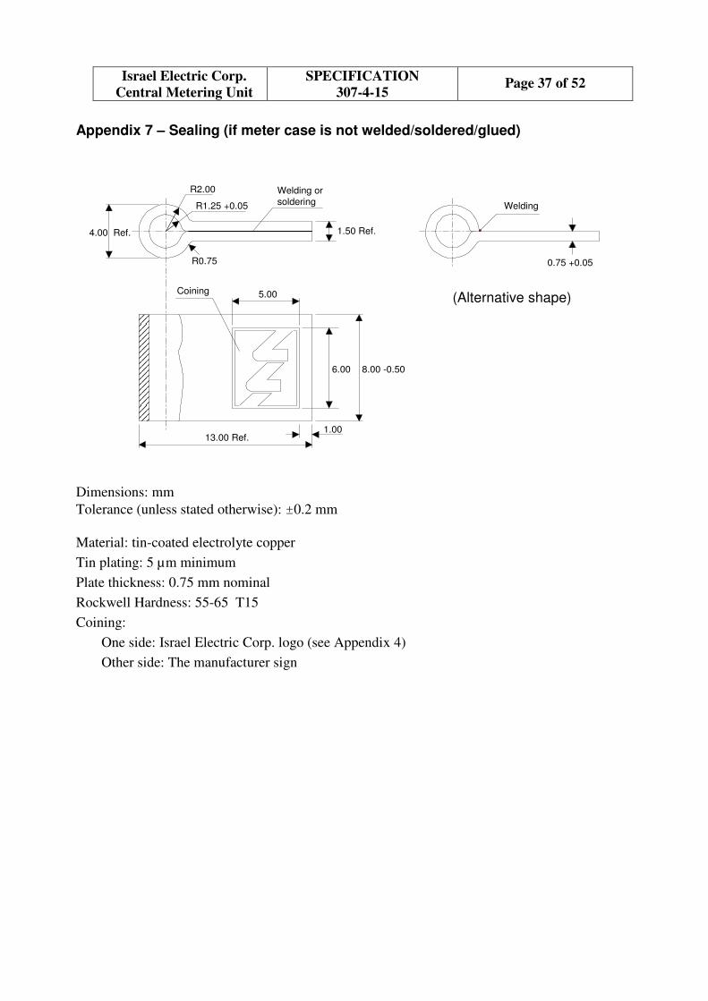
Appendix 7 – Sealing (if meter case is not welded/soldered/glued)
R2.00
R1.25 +0.05
1.50 Ref.
R0.75
4.00 Ref.
Welding or
soldering
6.00 8.00 -0.50
13.00 Ref.1.00
Coining 5.00
0.75 +0.05
Welding
(Alternative shape)
Dimensions: mm
Tolerance (unless stated otherwise): ±0.2 mm
Material: tin-coated electrolyte copper
Tin plating: 5 µm minimum
Plate thickness: 0.75 mm nominal
Rockwell Hardness: 55-65 T15
Coining:
One side: Israel Electric Corp. logo (see Appendix 4)
Other side: The manufacturer sign
Page 38 of 52 SPECIFICATION
307-4-15
Israel Electric Corp.
Central Metering Unit
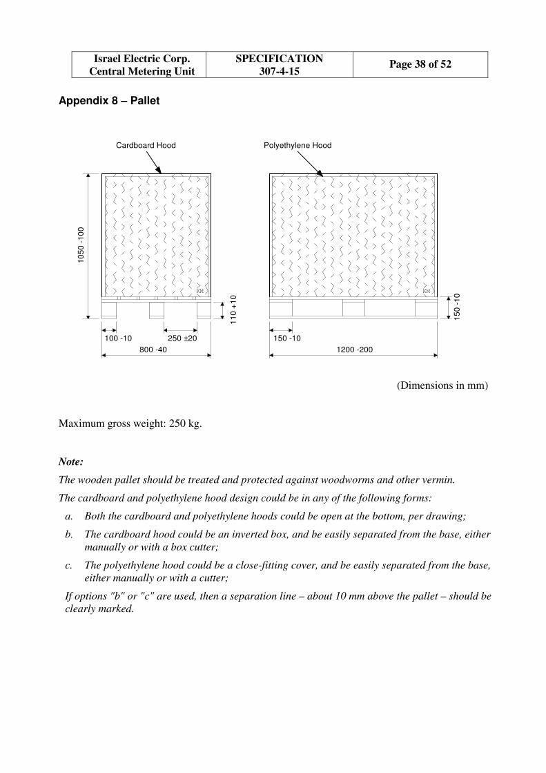
Appendix 8 – Pallet
10
50
-1
00
250 ±20100 -10
800 -40
11
0 +
10
15
0 -
10
150 -10
1200 -200
KMKM
Cardboard Hood Polyethylene Hood
(Dimensions in mm)
Maximum gross weight: 250 kg.
Note:
The wooden pallet should be treated and protected against woodworms and other vermin.
The cardboard and polyethylene hood design could be in any of the following forms:
a. Both the cardboard and polyethylene hoods could be open at the bottom, per drawing;
b. The cardboard hood could be an inverted box, and be easily separated from the base, either
manually or with a box cutter;
c. The polyethylene hood could be a close-fitting cover, and be easily separated from the base,
either manually or with a cutter;
If options "b" or "c" are used, then a separation line – about 10 mm above the pallet – should be
clearly marked.

Page 39 of 52 SPECIFICATION
307-4-15
Israel Electric Corp.
Central Metering Unit
Appendix 9 – Off the Shelf Product Requirements
The Meter shall be an "off the shelf" product, complying with the requirements defined below.
The Product:
• Is completely defined (design, construction and performance) by a formal technical
specification.
• Is manufactured in accordance with formal production drawings, processes and procedures
which govern all stages and aspects of the manufacturing process.
• Has successfully passed all qualification tests and type tests in particular.
• Is currently manufactured, with at least 200,000 operating units supplied to electric utilities
during the last three years, and the accumulated operational data proves high reliability
indicating that the product is mature.
• Is regularly checked for reliability by field data collection, collation and corrective actions
taken when needed.
• Is accompanied by a complete set of drawings and procedures, reliability prediction, user
manuals and maintenance manuals. The awarded bidder is requested to submit these
documents to I.E.Co.
Page 40 of 52 SPECIFICATION
307-4-15
Israel Electric Corp.
Central Metering Unit
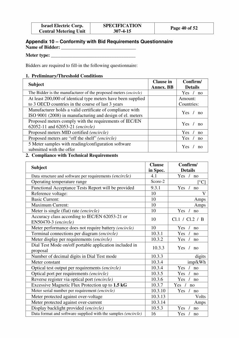
Appendix 10 – Conformity with Bid Requirements Questionnaire Name of Bidder: _______________________________
Meter type: ___________________________________
Bidders are required to fill-in the following questionnaire:
1. Preliminary/Threshold Conditions
Subject Clause in
Annex. BB
Confirm/
Details The Bidder is the manufacturer of the proposed meters (encircle) Yes / no
At least 200,000 of identical type meters have been supplied
to 3 OECD countries in the course of last 3 years
Amount:
Countries:
Manufacturer holds a valid certificate of compliance with
ISO 9001 (2008) in manufacturing and design of el. meters Yes / no
Proposed meters comply with the requirements of IEC/EN
62052-11 and 62053-21 (encircle) Yes / no
Proposed meters MID certified (encircle) Yes / no
Proposed meters are “off the shelf” (encircle) Yes / no
5 Meter samples with reading/configuration software
submitted with the offer Yes / no
2. Compliance with Technical Requirements
Subject Clause
in Spec.
Confirm/
Details
Data structure and software per requirements (encircle) 4.1 Yes / no
Operating temperature range Score-2 [°C]
Functional Acceptance Tests Report will be provided 9.3.1 Yes / no
Reference voltage: 10 V
Basic Current: 10 Amps
Maximum Current: 10 Amps
Meter is single (flat) rate (encircle) 10 Yes / no
Accuracy class according to IEC/EN 62053-21 or
EN50470-3 (encircle) 10 Cl.1 / Cl.2 / B
Meter performance does not require battery (encircle) 10 Yes / no
Terminal connections per diagram (encircle) 10.3.1 Yes / no
Meter display per requirements (encircle) 10.3.2 Yes / no
Dial Test Mode on/off portable application included in
proposal 10.3.3 Yes / no
Number of decimal digits in Dial Test mode 10.3.3 digits
Meter constant 10.3.4 imp/kWh
Optical test output per requirements (encircle) 10.3.4 Yes / no
Optical port per requirements (encircle) 10.3.5 Yes / no
Reverse register via optical port (encircle) 10.3.6 Yes / no
Excessive Magnetic Flux Protection up to 1.5 kG 10.3.7 Yes / no Meter serial number per requirement (encircle) 10.3.10 Yes / no
Meter protected against over-voltage 10.3.13 Volts
Meter protected against over-current 10.3.14 Amps
Display backlight provided (encircle) 10.5.3 Yes / no Data format and software supplied with the samples (encircle) 16 Yes / no

Page 41 of 52 SPECIFICATION
307-4-15
Israel Electric Corp.
Central Metering Unit
3. Physical Characteristics
Subject Clause in
Spec.
Confirm/
Details
Meter dimensions including terminal cover 10.4.1 mm x mm x mm
Bottom mounting holes per requirements (encircle) 10.4.2 Yes / no
Meter weight 10.4.3 kg
Double Insulation 10.5.1 class
Protection against moisture and dust penetration (IP 51) 10.5.1 Yes / no
UV radiation resistant window 10.5.2 material
Voltage links not accessible (inside meter case) (encircle) 10.5.4 Yes / no
Sealing of meter cover (welded/glued, screws) 10.5.5 type
Tamper evidence sticker (if not welded/glued) (encircle) 10.5.5 Yes / no
Terminal material 10.5.6.1 material
Terminal type ("pillar-bar" / "lift") 10.5.6.1 type
Terminal screws material and finishing 10.5.6.2 material
Max allowed torque applied to pinching screw 10.5.6.2 Nm
Bore diameter of terminals, including neutral 10.5.6.1 mm
Non-breakable terminal block cover material 10.5.6.3 material
Self-extinguishing terminal cover 10.5.6.3 class
Free space of terminal cover 10.5.6.3 mm
Shaped-head screw with protective sleeve (encircle) 10.5.6.3 Yes / no
Connection diagram inside terminal cover with terminals
marking (encircle) 10.5.6.3 Yes / no
Nameplate with IEC/EN 62052-11 requirements, I.E.Co
code and logo, and bar code (encircle) 14 Yes / no
4. Qualitative Supply Requirements
Subject Clause
in Spec.
Confirm/
Details
QA program per ISO 9001 (2008) (encircle) 7 Yes / no Manufacturing capacity sufficient for timely supply (encircle) 7.1.4 Yes / no
100% AC insulation test before shipment 9.3.2 Yes / no Meters are calibrated with voltage links …… 9.3.2 open / closed Closed voltage links position is checked before packaging 9.3.2 Yes / no Factory test results (insulation + metrology) will be sent to
I.E.Co on electronic media (encircle) 9.3.2 Yes / no
Modifications subject to prior agreement (encircle) 10.5.7 agree / disagree
Replaced manufacturing line subject to approval (encircle) 10.5.7 agree / disagree
Preproduction series lot will be made available (encircle) 10.6.1 Yes / no Procedure for defective meters will be per IEC 62058-11
(encircle) 10.6.2
Yes / no
Expedited extra delivery available to cover defectives (encircle) 10.6.2 Yes / no
Repair/replacement under warranty at no cost (encircle) 10.7.1 agree / disagree
Excessive faults shall double the warranty period (encircle) 10.7.1 agree / disagree
Warranty period 10.7.1 months
Spare parts available for 5 years (encircle) 10.7.2 Yes / no
Accelerated Life tests results provided (encircle) 11.1 Yes / no

Page 42 of 52 SPECIFICATION
307-4-15
Israel Electric Corp.
Central Metering Unit
Meters will be supplied in piles/pallets (encircle) 12 Yes / no
Number of meters packed in one group box 12 pcs
Sturdy box, with wall thickness at least 4 mm (encircle) 12 Yes / no Boxes and hoods marked with required info. (encircle) 12 Yes / no
Pallet protected by polyethylene wrap and hood (encircle) 12 Yes / no
Impact detectors included (encircle) 12 Yes / no
Pallet dimensions 12,
App. 8
mm x mm x mm
Number of meters packed in pallet 12 pcs
Pallet gross weight App. 8 kg
Note: The "Details" must be a concrete answer on appropriate requirement, including a short
description and references.
5. Checklist of main documents preliminarily provided with the offer
Document Clause in
Spec./Annex BB
Confirmation
of supply
IEC/EN 62052-11 and 62053-21 or MID compliance
certificate 9.2.1
ISO 9001 (2008) certificate 9.2.2
Type approval certificate 9.2.1
Type test results report 9.2.1
List of customers incl. meter type and sold quantities 9.2.3
Customers' confirmations of purchased quantities 9.2.3
Complete description of the meter 9.2.9
Filled Manufacturers’ Questionnaire 9.2.4, App. 11
Filled RAM questionnaire 9.2.5, 10.2
Manufacturer Quality Management Guide 9.2.6
List of test equipment for initial calibration 9.2.8
Calibration certificates for test equipment 9.2.8
Traceability charts for test equipment 9.2.8
LCD grade statement 10.3.2
5 meter samples delivery note 16
Note: all relevant documents that are not listed here must be also provided with the offer.
Manufacturer Part Numbers (please fill-in):
Type Part No. I.E.Co Cat. No.
Meter 4453502
Terminal cover 4249389
Terminal screws 4249397
Clip-on mounting bracket 5247517
Page 43 of 52 SPECIFICATION
307-4-15
Israel Electric Corp.
Central Metering Unit
Appendix 11 – Manufacturer's Qualification Questionnaire
Note: The data provided in this appendix should refer only to the plant where the meters are
manufactured.
1. General
1.1 Company’s Name: ___________________________________________________
1.2 Commercial Address: _________________________________________________
___________________________________________________________________
1.3 Telephone No.: ______________________________________________________
1.4 Fax No.: ___________________________________________________________
1.5 Questionnaire Respondent’s Personal Data:
Name: _____________________________________________________________
Position: ___________________________________________________________
Telephone No. (if different to 1.3 above) _________________________________
Date: _________________ Signature: ___________________________
2. Company Profile
2.1 General Description of the Company (e.g. Manufacturer of ...):
____________________________________________________________________
____________________________________________________________________
2.2 Management Organization (attach organization chart showing directors and other key
personnel):
____________________________________________________________________
____________________________________________________________________
2.2.1 Corporate Structure:
____________________________________________________________________
2.2.2 Management Organization of the Manufacturing Division/Plant/Service directly responsible
for manufacturing the Equipment or supply the Service.
___________________________________________________________________
2.2.3 Local Israeli Agent (if any):
Name: _____________________________________________________________
Address: __________________________________________________________

Page 44 of 52 SPECIFICATION
307-4-15
Israel Electric Corp.
Central Metering Unit
Phone No.: ________________________________________________________
For what purposes: _________________________________________________
2.3 The profile of the Company Field
� System Engineering ____________________________________________
� Product Engineering ____________________________________________
� Manufacturing _________________________________________________
� Construction/Erection ___________________________________________
� Services ______________________________________________________
2.4 Describe ownership capital and share structure:
___________________________________________________________________
___________________________________________________________________
2.4.1 Authorized Capital: _____________________
2.4.2 Issued Capital: _________________________
2.5 Annual value of work undertaken for each of the last five years and projected for the current
year:
__________________________________________________________________
2.5.1 Home: ____________________________________________________________
2.5.2 Internationally: _____________________________________________________
2.6 Attach the most recent audited financial report (profit/loss, assets, liabilities, balance sheet),
and for the two previous years.
___________________________________________________________________
___________________________________________________________________
2.7 Names and addresses of associated companies, if any, to be involved in the project and
whether as joint venture, parent, subsidiary or other.
___________________________________________________________________
___________________________________________________________________
2.8 If Company responding is a subsidiary, describe the extent of involvement, if any, of the
parent company in the Project, administratively, technically, financially, other.
___________________________________________________________________
___________________________________________________________________
2.9 Name and address of Bankers from whom references can be obtained.
__________________________________________________________________

Page 45 of 52 SPECIFICATION
307-4-15
Israel Electric Corp.
Central Metering Unit
__________________________________________________________________
3. Company Capabilities
3.1 General
3.1.1 Total turnover (specify total turnover for the last five years, yearly)
__________________________________________________________________
__________________________________________________________________
__________________________________________________________________
3.1.2 Detail amount of raw materials purchased by the company for the last five years (answer if
corresponds to your activities).
__________________________________________________________________
__________________________________________________________________
__________________________________________________________________
3.1.3 Describe the main products and services.
__________________________________________________________________
__________________________________________________________________
__________________________________________________________________
3.1.4 Give details of the principal equipment, which has been designed and/or manufactured:
__________________________________________________________________
__________________________________________________________________
__________________________________________________________________
3.1.5 Indicate number of years of experience as supplier of Product in:
3.1.5.1 Own country: ________________________________________________
3.1.5.2 International Market: ___________________________________________
3.1.6 Number of years experience as subcontractor/sub-supplier in:
3.1.6.1 Own country: _______________________________________________
3.1.6.2 International market: _________________________________________
3.1.7 Give a reference list of the major works (or contracts) that the Company had carried out
recently (last five years). Specify at least:
a. Location of the project;
b. Year of project was put in operation;
c. Materials handling with the equipment;
d. Principal technical parameters;
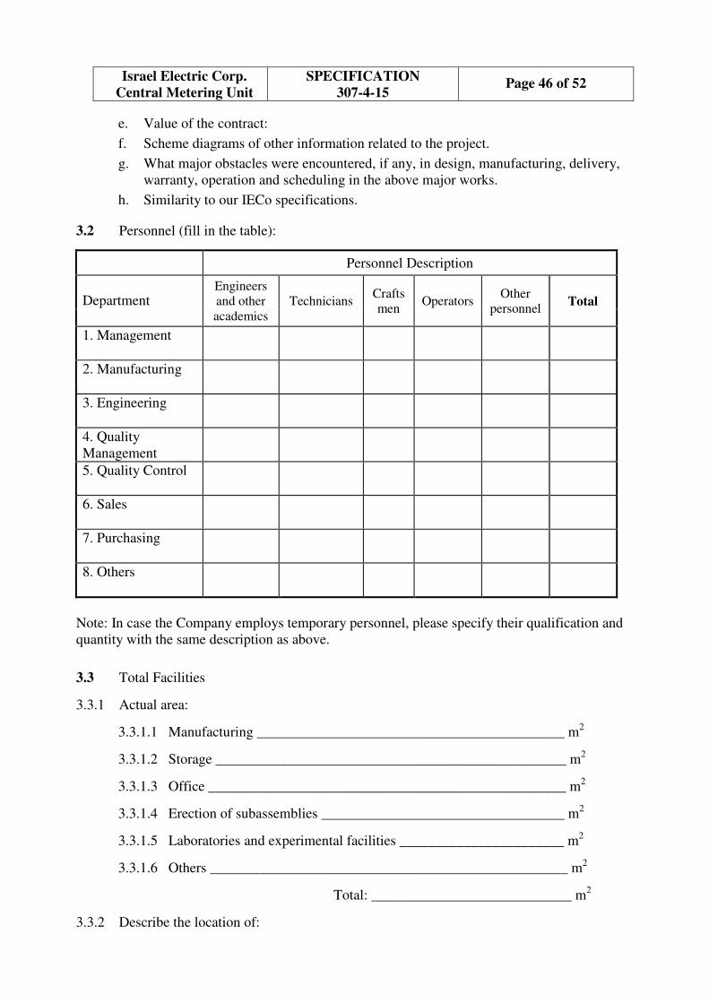
Page 46 of 52 SPECIFICATION
307-4-15
Israel Electric Corp.
Central Metering Unit
e. Value of the contract:
f. Scheme diagrams of other information related to the project.
g. What major obstacles were encountered, if any, in design, manufacturing, delivery,
warranty, operation and scheduling in the above major works.
h. Similarity to our IECo specifications.
3.2 Personnel (fill in the table):
Personnel Description
Department Engineers
and other
academics
Technicians Crafts
men Operators
Other
personnel Total
1. Management
2. Manufacturing
3. Engineering
4. Quality
Management
5. Quality Control
6. Sales
7. Purchasing
8. Others
Note: In case the Company employs temporary personnel, please specify their qualification and
quantity with the same description as above.
3.3 Total Facilities
3.3.1 Actual area:
3.3.1.1 Manufacturing ___________________________________________ m2
3.3.1.2 Storage _________________________________________________ m2
3.3.1.3 Office __________________________________________________ m2
3.3.1.4 Erection of subassemblies __________________________________ m2
3.3.1.5 Laboratories and experimental facilities _______________________ m2
3.3.1.6 Others __________________________________________________ m2
Total: ____________________________ m
2
3.3.2 Describe the location of:

Page 47 of 52 SPECIFICATION
307-4-15
Israel Electric Corp.
Central Metering Unit
3.3.2.1 Main office ________________________________________________________
___________________________________________________________________
3.3.2.2 Main facilities ______________________________________________________
___________________________________________________________________
3.3.2.3 Main machinery available in the above facilities ___________________________
___________________________________________________________________
___________________________________________________________________
3.3.2.4 Access to the Manufacturing and Erection facilities _________________________
___________________________________________________________________
___________________________________________________________________
3.3.3 Detail the manufacturing capability: ______________________________________
___________________________________________________________________
___________________________________________________________________
___________________________________________________________________
___________________________________________________________________
3.3.4 Capacity for manufacturing the offered Meter: ________________ units / month.
3.4 Technological Capability
3.4.1 List the national and international standards used in design ____________________
___________________________________________________________________
___________________________________________________________________
___________________________________________________________________
3.4.2 Specify the relevant licensing agreements signed, with whom and their purposes.
___________________________________________________________________
___________________________________________________________________
___________________________________________________________________
___________________________________________________________________
3.4.3 Specify the relevant “patent use” agreements signed, with whom and their purposes.
___________________________________________________________________
___________________________________________________________________
___________________________________________________________________

Page 48 of 52 SPECIFICATION
307-4-15
Israel Electric Corp.
Central Metering Unit
___________________________________________________________________
4. Quality Management and Quality Control Organization
4.1 Specify the quality level the company and its subsidiaries are qualified, according to which
standards, and the name of the accreditation bodies.
___________________________________________________________________
4.2 Do you have your own Quality Management Manual and/or Quality Control Manual?
(Yes/No - give details)
___________________________________________________________________
4.3 Does your company have and utilize Quality Control procedures and instructions?
(Detail titles and date of approval).
___________________________________________________________________
4.3.1 For purchasing materials, components, equipment (Yes/No)
___________________________________________________________________
4.3.2 For use and maintenance of equipment (Yes/No)
___________________________________________________________________
4.3.3 For acceptance test of purchased material/components (Yes/No)
___________________________________________________________________
Indicate where it takes place ____________________________________________
___________________________________________________________________
4.3.4 For materials and products handling and storage (Yes/No)
___________________________________________________________________
4.3.5 For fabrication processes (Yes/No) (indicate name of procedures)
___________________________________________________________________
4.3.6 For shipping (Yes/No)
___________________________________________________________________
4.3.7 For final inspection of your products before delivery (Yes/No)
___________________________________________________________________
4.3.8 Do you consider your procedures and instructions are as contractual with your client?
___________________________________________________________________
4.4 Internal Documentation and Certificates:
4.4.1 Are there any procedures regarding the issuance, distribution and retrieval system?

Page 49 of 52 SPECIFICATION
307-4-15
Israel Electric Corp.
Central Metering Unit
For the documentation issued for:
Processes: _________________________________________________________
Material certificates: _________________________________________________
Inspection and tests: _________________________________________________
Documents for approval by the purchaser: ________________________________
4.5 Does your company have procedures for design review and control? (Yes/No)
(detail names and dates of approval).
___________________________________________________________________
___________________________________________________________________
4.6 Describe the procedure applied to materials and products with defects:
___________________________________________________________________
___________________________________________________________________
4.7 Describe the capability (human resources, equipment, facilities, technology, etc.) to perform:
4.7.1 Measurements _______________________________________________________
4.7.2 Special tests _________________________________________________________
4.7.3 Calibration system ____________________________________________________
5. Engineering Organization
5.1 List current Executive Directors, if any, within the engineering organization (only to be
answered if specially indicated by IECo)
5.1.1 Name: _____________________________________________________________
5.1.2 Present Position held __________________________, since __________________
5.1.3 Years experience in profession __________________________________________
5.1.4 Years experience in company ___________________________________________
5.2 List key personnel who would be assigned to Project (If more than one, please add extra
sheets).
5.2.1 Name: _____________________________________________________________
5.2.2 Present Position held __________________________, since _________________
5.2.3 Years experience in profession _______________________________________
5.2.4 Years experience in company ________________________________________
5.2.5 Would such person(s) be solely assigned to the Project?
(Yes/No) _________________________________________________________
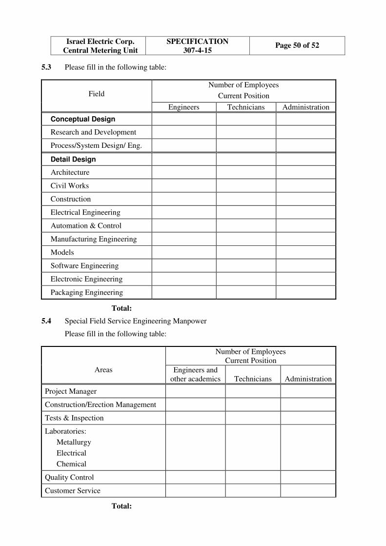
Page 50 of 52 SPECIFICATION
307-4-15
Israel Electric Corp.
Central Metering Unit
5.3 Please fill in the following table:
Field
Number of Employees
Current Position
Engineers Technicians Administration
Conceptual Design
Research and Development
Process/System Design/ Eng.
Detail Design
Architecture
Civil Works
Construction
Electrical Engineering
Automation & Control
Manufacturing Engineering
Models
Software Engineering
Electronic Engineering
Packaging Engineering
Total:
5.4 Special Field Service Engineering Manpower
Please fill in the following table:
Areas
Number of Employees
Current Position
Engineers and
other academics
Technicians
Administration
Project Manager
Construction/Erection Management
Tests & Inspection
Laboratories:
Metallurgy
Electrical
Chemical
Quality Control
Customer Service
Total:
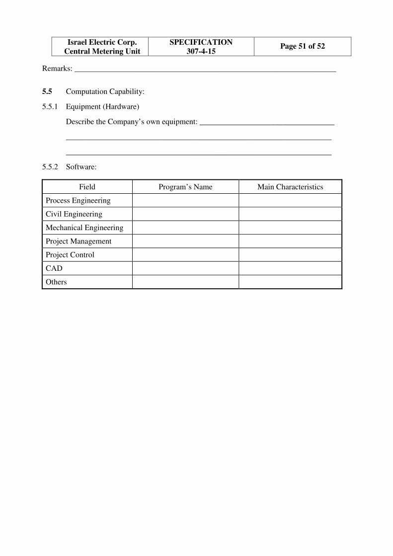
Page 51 of 52 SPECIFICATION
307-4-15
Israel Electric Corp.
Central Metering Unit
Remarks: __________________________________________________________________
5.5 Computation Capability:
5.5.1 Equipment (Hardware)
Describe the Company’s own equipment: __________________________________
___________________________________________________________________
___________________________________________________________________
5.5.2 Software:
Field Program’s Name Main Characteristics
Process Engineering
Civil Engineering
Mechanical Engineering
Project Management
Project Control
CAD
Others
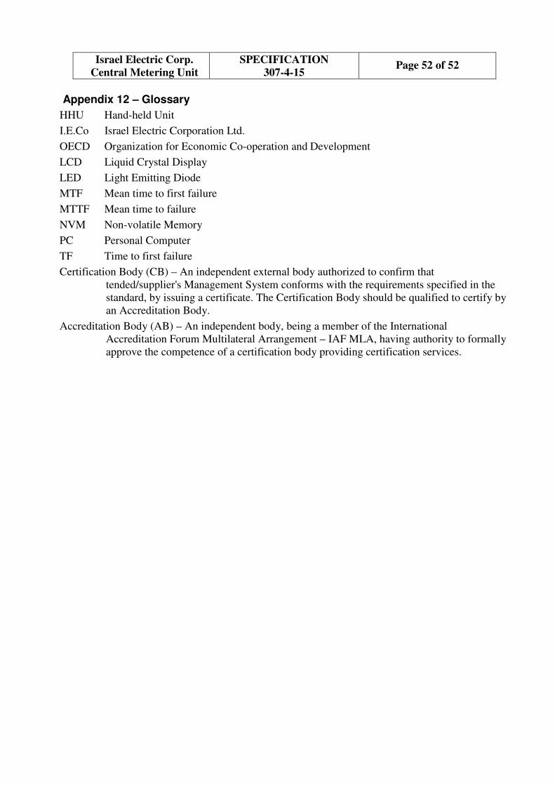
Page 52 of 52 SPECIFICATION
307-4-15
Israel Electric Corp.
Central Metering Unit
Appendix 12 – Glossary
HHU Hand-held Unit
I.E.Co Israel Electric Corporation Ltd.
OECD Organization for Economic Co-operation and Development
LCD Liquid Crystal Display
LED Light Emitting Diode
MTF Mean time to first failure
MTTF Mean time to failure
NVM Non-volatile Memory
PC Personal Computer
TF Time to first failure
Certification Body (CB) – An independent external body authorized to confirm that
tended/supplier's Management System conforms with the requirements specified in the
standard, by issuing a certificate. The Certification Body should be qualified to certify by
an Accreditation Body.
Accreditation Body (AB) – An independent body, being a member of the International
Accreditation Forum Multilateral Arrangement – IAF MLA, having authority to formally
approve the competence of a certification body providing certification services.