Embed Size (px)
Citation preview
Published: June 29, 2011
r 2011 American Chemical Society 15124 dx.doi.org/10.1021/jp112157z | J. Phys. Chem. C 2011, 115, 15124–15132
ARTICLE
pubs.acs.org/JPCC
The Influence of Inorganic Filler Particle Size on CompositeIon-Exchange Membranes for DesalinationChalida Klaysom,† Seung-Hyeon Moon,‡ Bradley P. Ladewig,†,§ G. Q. Max Lu,*,† and Lianzhou Wang*,†
†ARC Centre of Excellence for Functional Nanomaterials, School of Chemical Engineering and Australian Institute of Bioengineeringand Nanotechnology, The University of Queensland, Qld 4072, Australia‡Gwangju Institute of Science and Technology, School of Environmental Science and Engineering, Gwangju 500-712, Republic of Korea§Monash University, Department of Chemical Engineering, Vic 3800, Australia
bS Supporting Information
1. INTRODUCTION
Ion-exchange membranes (IEMs) have attracted much inter-est in a variety of applications ranging from the food industry andfuel cells to desalination. The development of new IEMs withgood selectivity and high chemical, thermal, and mechanicalstability to meet the growing demand of such a versatile applica-tion is of significant importance. A number of advanced polymerprocesses have been developed and applied to the fabrication ofnew IEMs, including chemical modification of polymer chainsand the use of hybrid organic�inorganic materials.1�10 Greateffort has been dedicated to developing polymeric membraneswith high conductivity and selectivity mainly by chemical mod-ification of the polymer backbone to obtain a high degree of ion-exchange capacity.1�5 However, chemical modification in such ahigh degree often results in a highly swollen membrane and lowmechanical stability.1�5 Therefore, a fabric support or a certaindegree of cross-linkage is required to give the strength to themembranes. Recently, the concept of combining two distinctmaterials to form composites that retain desirable propertiesfrom both components has been intensively studied in thedevelopment of membranes, particularly for fuel cell application.For polymer-based composites, the purposes of adding inorganic
additives aremainly to improve thermal, chemical, andmechanicalproperties of polymer matrix while keeping their flexible andprocessable properties and chemical functionalities.Many researchgroups utilize inorganic fillers to improve the water uptake ofproton-exchange membranes at high working temperatures.7�10
The studies revealed that functionalized inorganic fillers couldprovide extra functional groups for proton exchange and also keptmoisture inside the structure to assist proton migration, whichconsequently improved proton conductivity at high workingtemperatures in fuel cell applications.7,10 Though the compositeconcept was also demonstrated to be a promising approach fordeveloping IEMs for various applications, much fewer studies havebeen reported in important water purification application, such aselectrodialysis (ED) desalination.11�13
In fact, the ion conductivity of IEMs depends not only on theion-exchange capacity (IEC) but also on the water content andmo-bility of the ions, which are closely linked to the structural propertiesof the membranes.14 Recently, we have developed a group of new
Received: December 22, 2010Revised: June 24, 2011
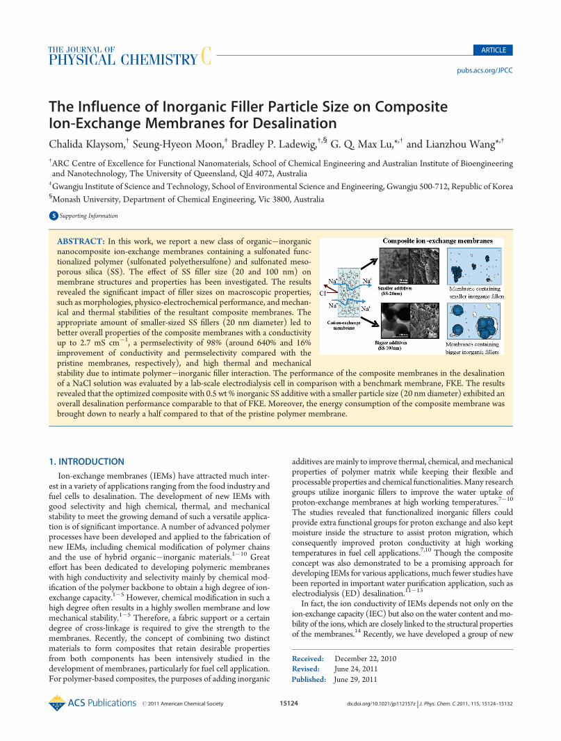
ABSTRACT: In this work, we report a new class of organic�inorganicnanocomposite ion-exchange membranes containing a sulfonated func-tionalized polymer (sulfonated polyethersulfone) and sulfonated meso-porous silica (SS). The effect of SS filler size (20 and 100 nm) onmembrane structures and properties has been investigated. The resultsrevealed the significant impact of filler sizes on macroscopic properties,such as morphologies, physico-electrochemical performance, and mechan-ical and thermal stabilities of the resultant composite membranes. Theappropriate amount of smaller-sized SS fillers (20 nm diameter) led tobetter overall properties of the composite membranes with a conductivityup to 2.7 mS cm�1, a permselectivity of 98% (around 640% and 16%improvement of conductivity and permselectivity compared with thepristine membranes, respectively), and high thermal and mechanicalstability due to intimate polymer�inorganic filler interaction. The performance of the composite membranes in the desalinationof a NaCl solution was evaluated by a lab-scale electrodialysis cell in comparison with a benchmark membrane, FKE. The resultsrevealed that the optimized composite with 0.5 wt % inorganic SS additive with a smaller particle size (20 nm diameter) exhibited anoverall desalination performance comparable to that of FKE. Moreover, the energy consumption of the composite membrane wasbrought down to nearly a half compared to that of the pristine polymer membrane.
15125 dx.doi.org/10.1021/jp112157z |J. Phys. Chem. C 2011, 115, 15124–15132
The Journal of Physical Chemistry C ARTICLE
organic�inorganic composite IEMs based on sulfonated poly-ethersulfone (sPES), a high-performance thermoplastic, andsulfonated mesoporous silica (SS) nanoparticles.15,16 While thepolymer (sPES) provides good thermal and mechanical stability,the SS supplies additional functional groups, enhancing IEC,water uptake, conductivity, and selectivity of the compositemembranes.
It was well known that some key parameters have to beconsidered when incorporating inorganic fillers in a polymermatrix. Among those parameters, aspect ratio and size of fillersare of considerable importance due to the changes of interfacialproperties in the composites.17 In the newly developed sPES�SScomposite membrane system, we have demonstrated an alter-native, easy approach to improve the conductivity and electro-chemical properties of the membranes by tuning the membranestructure with surface functionalized inorganic fillers that carryextra ion-exchangeable functional groups. In this work, we fur-ther report our new findings on the significant effect of inorganicfiller sizes on the structure and performance of compositemembranes in desalination application, which has been rarelystudied.17 It is evident that an appropriate amount of small-sizedSS fillers can result in an overall desalination performance com-parable to the commercial membrane FKE. It is expected that thisstudy will lead to a better understanding on how to design newcompositemembranes with a controllable structure and desirableproperties for a niche application.
2. EXPERIMENTAL SECTION
2.1. Preparation of the Sulfonated Mesoporous SiO2. TheSS particles with a diameter of 20 nm were prepared by a so-called liquid-phase method with the assistance of a basic aminoacid.18 Typically, the solution containing 360 g of DI water,1.664 g of cetylmethylammonium chloride (C16TMACl, TokyoChemical Industry), and 0.209 g of amino acid arginine (Arg,Sigma-Aldrich, 98%) was prepared at room temperature undervigorous stirring, followed by the addition of 2.083 g of tetraethylorthosilicate (TEOS, Fluka, 98%). The resultant solution wasstirred continuously at 60 �C for 24 h. The reaction was thenterminated, and the highly dispersed silica was obtained. Thesilica powders were then collected by solvent evaporation,followed by calcination at 500 �C in air for 10 h to remove theresidual reactants. The surface of the as-synthesized silica wasfunctionalized with the sulfonate group via a grafting method.19
More specifically, 0.6 g of calcined silica was dispersed in 100 cm3
of dry toluene. The mixture solution was heated at 110 �C andstirred under reflux. A 0.6 cm3 portion of mercaptopropyltrimethoxysilane (MPTMS, Sigma) was added in the mixturesolution, and the reaction continued for 16 h. The graftedpowder was collected by centrifugation and washed with acetoneseveral times before it was redispersed in 10 cm3 of H2O2 at roomtemperature for 48 h. The suspended powders were centrifugedand added into 30 cm3 of 1 mol dm�3 H2SO4 under stirringfor 2 h. The surface functionalization procedure was completedby filtering the modified particles and drying them at roomtemperature.The highly ordered mesoporous silica with a size of 100�
150 nm was prepared according to our previous studies.9,20 Thesulfonated mesoporous silica with two different particle sizes,20 and 100 nm, was named SS-20 nm and SS-100 nm, respec-tively. Note that the as-synthesized powders were ground toreduce the agglomeration before being added into the polymer
matrix. The surface sulfonation of the mesoporous silica led tothe decrease of both the specific surface area and the pore volumedue to the grafting and pore filling of functional SO3 groups onthe inner surface of the mesopores.9
The ion-exchange capacity of the SO3H-functionalizedmesoporous SiO2 was measured by back-titration. The struc-ture and morphology of the SS were studied by transmissionelectron microscopy (TEM, JEOL 1010) and X-ray diffraction(XRD, Rigaku Miniflex, Cu KR, 30 kV and 15 mA). Nitrogenadsorption�desorption isotherms were conducted at 77 K(Quadrasorb SI). The BET (Brunauer�Emmett�Teller) spe-cific surface area (ABET) and pore size distribution using the BJHmethod were calculated from the adsorption and desorptiondata, respectively.2.2. Membrane Preparation. The sulfonated polyethersul-
fone (sPES) was used as the polymer matrix for the compositemembranes.20,21 Typically, 25 wt % polymer solutions in di-methylformamide (DMF, Sigma) were first prepared. The SS(0�2 wt %) was then mixed with the polymer solutions at 60 �Cfor 4 h under stirring. Sonication with 25% intensity was appliedto the mixture solution for 3 min (Branson Digital Sonifier 450,output 400 W) before it was cast onto glass substrates using adoctor blade to control the casting film thickness at ca. 0.40 mm,followed by a two-step phase inversion process, which is acombination process of solvent evaporation and phase immer-sion technique. The cast film was then dried in a vacuum oven at60 �C for 10 min and precipitated in a 60�70 �C DI water bath.Afterward, the as-prepared membrane sheet with a thickness of50 ( 10 μm was obtained and kept in DI water. A series ofmembranes were named referring to the weight percent of SSadded in the polymer matrix. For instance, 0.2SS-20 nm is theabbreviation for the composite membranes of sPES containing0.2 wt % of SS of 20 nm. The resultant membranes wereequilibrated in the working solution for at least 6 h before use.2.3. Membrane Characterization. Morphology and Physi-
cochemical Properties. Scanning electron microscopy (SEM,JEOL 6300) and transmission electron microscopy (TEM, JEOL1010) were used to observe the morphology and the distributionof inorganic SS fillers in the polymer matrix of the preparedmembranes, respectively.Ion-exchange capacities (IECs) were measured by a titration
of substituted protons from the sulfonate functional groups ofthe prepared membranes equilibrated in NaCl solution. The IECwas estimated in terms of equivalent value of the substitutedproton per unit weight of dry membranes (mequiv g�1). Theterm “water uptake” refers to the amount of water content perunit weight of dry membranes, while the free volume fraction isthe ratio of water volume to the volume of wet membraneequilibrated in water.Electrochemical Properties.The electrochemical properties of
the membranes were investigated at room temperature by a two-compartment cell in which each chamber is separated by amembrane sample with an effective area of 1 cm2. The resistanceof membranes was measured by impedance spectroscopy (IS,Solarton 225B) in a working solution of 0.5 mol dm�3 NaClwith a frequency range of 1�106 Hz and an oscillating voltage of100 mV in amplitude.22
The selectivity of an IEM can be determined by two terms,transport number and permselectivity. The term “transportnumber” represents the fraction of total current carried bycounterions through the IEM, while the term “permselectivity”refers to how easily the counterions migrate through the IEM
15126 dx.doi.org/10.1021/jp112157z |J. Phys. Chem. C 2011, 115, 15124–15132
The Journal of Physical Chemistry C ARTICLE
compared to the co-ions. The potential difference (Em) acrossthe membrane was measured by a multimeter connecting to Ag/AgCl reference electrodes immersed in 0.01 mol dm�3 NaCl inone compartment and 0.05 mol dm�3 NaCl in the othercompartment. The transport number, ti, was then calculated byeq 1, and the permselectivity of the membrane was finallyestimated according to the resultant ti as defined by eq 2
Em ¼ RTnF
ð2t̅i � 1Þln a1a2
� �ð1Þ
Ps ¼ t̅i � ti1� ti
ð2Þ
where R is the gas constant, F the Faraday constant, T theabsolute temperature, a1 and a2 are the mean activities ofelectrolyte solutions in the testing cell, n the electrovalence ofthe counterion (ith), the concentrations of electrolyte solutionsin the testing cell, ti the transport number of the counterion in themembrane, and ti is that of the same ion in free solution at thesame concentration.The current�voltage characteristic and chronopotentiometry
(by Solartron Multistat 1480) were also used to study theelectrochemical behavior of the prepared membranes in 0.025mol dm�3 NaCl.
Thermal and Mechanical Stabilities. Thermal stability of themembranes was investigated using thermogravimetric analysis(TGA) (Mettler Teledo) under a nitrogen flow of 20 cm3 min�1
at a heating rate of 10 �Cmin�1. A tensile test by an Instron 5800was used to measure the mechanical properties of membranes ina wet state at room temperature.2.4. Desalination by Electrodialysis. The desalination per-
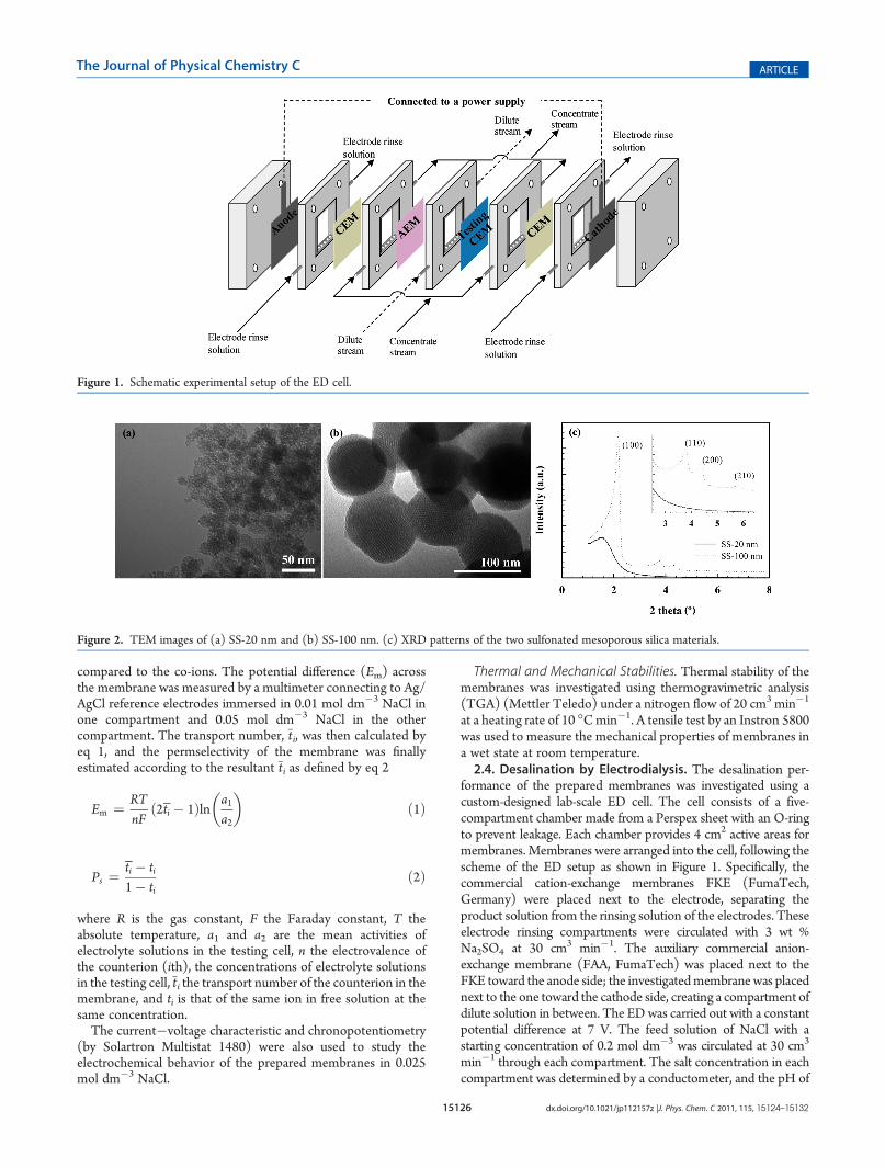
formance of the prepared membranes was investigated using acustom-designed lab-scale ED cell. The cell consists of a five-compartment chamber made from a Perspex sheet with an O-ringto prevent leakage. Each chamber provides 4 cm2 active areas formembranes. Membranes were arranged into the cell, following thescheme of the ED setup as shown in Figure 1. Specifically, thecommercial cation-exchange membranes FKE (FumaTech,Germany) were placed next to the electrode, separating theproduct solution from the rinsing solution of the electrodes. Theseelectrode rinsing compartments were circulated with 3 wt %Na2SO4 at 30 cm3 min�1. The auxiliary commercial anion-exchange membrane (FAA, FumaTech) was placed next to theFKE toward the anode side; the investigatedmembranewas placednext to the one toward the cathode side, creating a compartment ofdilute solution in between. The EDwas carried out with a constantpotential difference at 7 V. The feed solution of NaCl with astarting concentration of 0.2 mol dm�3 was circulated at 30 cm3
min�1 through each compartment. The salt concentration in eachcompartment was determined by a conductometer, and the pH of
Figure 1. Schematic experimental setup of the ED cell.
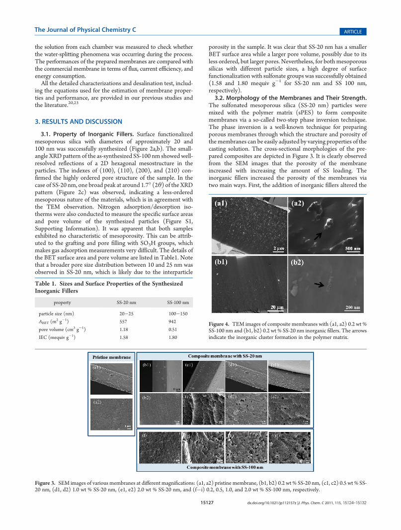
Figure 2. TEM images of (a) SS-20 nm and (b) SS-100 nm. (c) XRD patterns of the two sulfonated mesoporous silica materials.
15127 dx.doi.org/10.1021/jp112157z |J. Phys. Chem. C 2011, 115, 15124–15132
The Journal of Physical Chemistry C ARTICLE
the solution from each chamber was measured to check whetherthe water-splitting phenomena was occurring during the process.The performances of the prepared membranes are compared withthe commercial membrane in terms of flux, current efficiency, andenergy consumption.All the detailed characterizations and desalination test, includ-
ing the equations used for the estimation of membrane proper-ties and performance, are provided in our previous studies andthe literature.20,23
3. RESULTS AND DISCUSSION
3.1. Property of Inorganic Fillers. Surface functionalizedmesoporous silica with diameters of approximately 20 and100 nm was successfully synthesized (Figure 2a,b). The small-angle XRD pattern of the as-synthesized SS-100 nm showed well-resolved reflections of a 2D hexagonal mesostructure in theparticles. The indexes of (100), (110), (200), and (210) con-firmed the highly ordered pore structure of the sample. In thecase of SS-20 nm, one broad peak at around 1.7� (2θ) of the XRDpattern (Figure 2c) was observed, indicating a less-orderedmesoporous nature of the materials, which is in agreement withthe TEM observation. Nitrogen adsorption/desorption iso-therms were also conducted to measure the specific surface areasand pore volume of the synthesized particles (Figure S1,Supporting Information). It was apparent that both samplesexhibited no characteristic of mesoporosity. This can be attrib-uted to the grafting and pore filling with SO3H groups, whichmakes gas adsorption measurements very difficult. The details ofthe BET surface area and pore volume are listed in Table1. Notethat a broader pore size distribution between 10 and 25 nm wasobserved in SS-20 nm, which is likely due to the interparticle
porosity in the sample. It was clear that SS-20 nm has a smallerBET surface area while a larger pore volume, possibly due to itsless ordered, but larger pores. Nevertheless, for both mesoporoussilicas with different particle sizes, a high degree of surfacefunctionalization with sulfonate groups was successfully obtained(1.58 and 1.80 mequiv g�1 for SS-20 nm and SS 100 nm,respectively).3.2. Morphology of the Membranes and Their Strength.
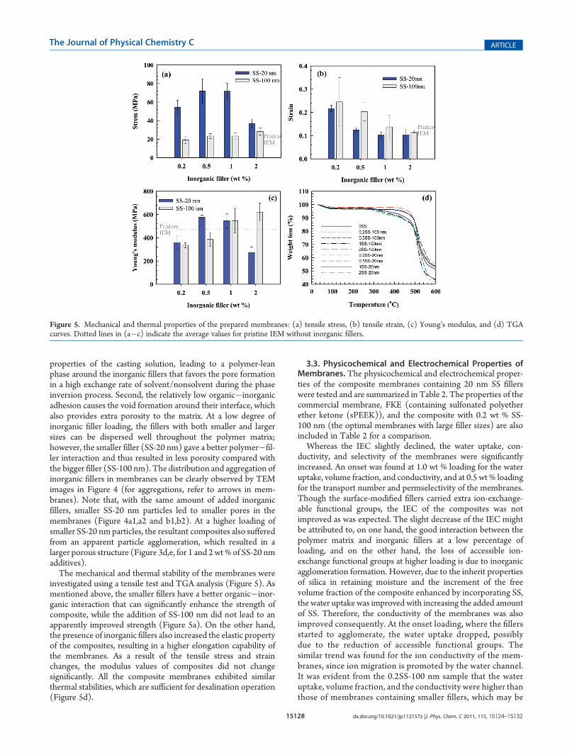
The sulfonated mesoporous silica (SS-20 nm) particles weremixed with the polymer matrix (sPES) to form compositemembranes via a so-called two-step phase inversion technique.The phase inversion is a well-known technique for preparingporous membranes through which the structure and porosity ofthemembranes can be easily adjusted by varying properties of thecasting solution. The cross-sectional morphologies of the pre-pared composites are depicted in Figure 3. It is clearly observedfrom the SEM images that the porosity of the membraneincreased with increasing the amount of SS loading. Theinorganic fillers increased the porosity of the membranes viatwo main ways. First, the addition of inorganic fillers altered the
Table 1. Sizes and Surface Properties of the SynthesizedInorganic Fillers
property SS-20 nm SS-100 nm
particle size (nm) 20�25 100�150
ABET (m2 g�1) 557 942
pore volume (cm3 g�1) 1.18 0.51
IEC (mequiv g�1) 1.58 1.80
Figure 3. SEM images of various membranes at different magnifications: (a1, a2) pristine membrane, (b1, b2) 0.2 wt % SS-20 nm, (c1, c2) 0.5 wt % SS-20 nm, (d1, d2) 1.0 wt % SS-20 nm, (e1, e2) 2.0 wt % SS-20 nm, and (f�i) 0.2, 0.5, 1.0, and 2.0 wt % SS-100 nm, respectively.
Figure 4. TEM images of composite membranes with (a1, a2) 0.2 wt %SS-100 nm and (b1, b2) 0.2 wt % SS-20 nm inorganic fillers. The arrowsindicate the inorganic cluster formation in the polymer matrix.
15128 dx.doi.org/10.1021/jp112157z |J. Phys. Chem. C 2011, 115, 15124–15132
The Journal of Physical Chemistry C ARTICLE
properties of the casting solution, leading to a polymer-leanphase around the inorganic fillers that favors the pore formationin a high exchange rate of solvent/nonsolvent during the phaseinversion process. Second, the relatively low organic�inorganicadhesion causes the void formation around their interface, whichalso provides extra porosity to the matrix. At a low degree ofinorganic filler loading, the fillers with both smaller and largersizes can be dispersed well throughout the polymer matrix;however, the smaller filler (SS-20 nm) gave a better polymer�fil-ler interaction and thus resulted in less porosity compared withthe bigger filler (SS-100 nm). The distribution and aggregation ofinorganic fillers in membranes can be clearly observed by TEMimages in Figure 4 (for aggregations, refer to arrows in mem-branes). Note that, with the same amount of added inorganicfillers, smaller SS-20 nm particles led to smaller pores in themembranes (Figure 4a1,a2 and b1,b2). At a higher loading ofsmaller SS-20 nm particles, the resultant composites also sufferedfrom an apparent particle agglomeration, which resulted in alarger porous structure (Figure 3d,e, for 1 and 2wt% of SS-20 nmadditives).The mechanical and thermal stability of the membranes were
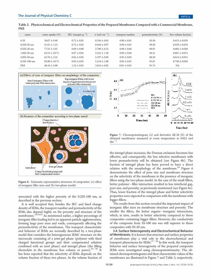
investigated using a tensile test and TGA analysis (Figure 5). Asmentioned above, the smaller fillers have a better organic�inor-ganic interaction that can significantly enhance the strength ofcomposite, while the addition of SS-100 nm did not lead to anapparently improved strength (Figure 5a). On the other hand,the presence of inorganic fillers also increased the elastic propertyof the composites, resulting in a higher elongation capability ofthe membranes. As a result of the tensile stress and strainchanges, the modulus values of composites did not changesignificantly. All the composite membranes exhibited similarthermal stabilities, which are sufficient for desalination operation(Figure 5d).
3.3. Physicochemical and Electrochemical Properties ofMembranes. The physicochemical and electrochemical proper-ties of the composite membranes containing 20 nm SS fillerswere tested and are summarized in Table 2. The properties of thecommercial membrane, FKE (containing sulfonated polyetherether ketone (sPEEK)), and the composite with 0.2 wt % SS-100 nm (the optimal membranes with large filler sizes) are alsoincluded in Table 2 for a comparison.Whereas the IEC slightly declined, the water uptake, con-
ductivity, and selectivity of the membranes were significantlyincreased. An onset was found at 1.0 wt % loading for the wateruptake, volume fraction, and conductivity, and at 0.5 wt % loadingfor the transport number and permselectivity of the membranes.Though the surface-modified fillers carried extra ion-exchange-able functional groups, the IEC of the composites was notimproved as was expected. The slight decrease of the IEC mightbe attributed to, on one hand, the good interaction between thepolymer matrix and inorganic fillers at a low percentage ofloading, and on the other hand, the loss of accessible ion-exchange functional groups at higher loading is due to inorganicagglomeration formation. However, due to the inherit propertiesof silica in retaining moisture and the increment of the freevolume fraction of the composite enhanced by incorporating SS,the water uptake was improved with increasing the added amountof SS. Therefore, the conductivity of the membranes was alsoimproved consequently. At the onset loading, where the fillersstarted to agglomerate, the water uptake dropped, possiblydue to the reduction of accessible functional groups. Thesimilar trend was found for the ion conductivity of the mem-branes, since ion migration is promoted by the water channel.It was evident from the 0.2SS-100 nm sample that the wateruptake, volume fraction, and the conductivity were higher thanthose of membranes containing smaller fillers, which may be
Figure 5. Mechanical and thermal properties of the prepared membranes: (a) tensile stress, (b) tensile strain, (c) Young’s modulus, and (d) TGAcurves. Dotted lines in (a�c) indicate the average values for pristine IEM without inorganic fillers.
15129 dx.doi.org/10.1021/jp112157z |J. Phys. Chem. C 2011, 115, 15124–15132
The Journal of Physical Chemistry C ARTICLE
associated with the higher porosity of the 0.2SS-100 nm, asdescribed in the previous section.It is well accepted that, besides the IEC and fixed change
density of IEMs, the transport number and permselectivity of theIEMs also depend highly on the porosity and structure of themembranes.14,24,25 As mentioned earlier, a higher percentage ofinorganic filler loading led to an apparent particle agglomeration,forming large pore sizes and voids, consequently affecting thepermselectivity of the membranes. The transport characteristicand behavior of IEMs are normally described by a two-phasemodel that considers the heterogeneous IEMs’ structure on themicroscale consisting of a joint-gel phase (polymer with fixedcharged functional groups and their compensated solutioncombined with an inert phase) and intergel phase (the fillingelectrolyte in the membrane free volume or pores).24�26 Ithas been reported that the selectivity of IEMs depends on thevolume fraction of these two phases. As the volume fraction of
the intergel phase increases, the Donnan exclusion becomes lesseffective, and consequently, the less selective membranes withlower permselectivity will be obtained (see Figure 6b). Thefraction of intergel phase has been proved to have a directrelation with the morphology of the membrane.24 Figure 6demonstrates the effect of pore size and membrane structureon the selectivity of the membrane in the presence of inorganicfillers using the two-phase model. In the case of the small fillers,better polymer�filler interaction resulted in less interfacial gap,pore size, and porosity, as previously mentioned (see Figure 6a).Thus, lower fraction of the intergel phase and better selectivityproperties were expected in comparison with the membrane withbigger fillers.The results from this section revealed the important impact of
inorganic filler sizes on membrane structure and porosity. Thesmaller the fillers, the better organic�inorganic interactions,which, in turn, results in better selectivity compared to thosecomposites containing bigger fillers. However, the conductivityof the composite from SS-100 nm was still superior to thosecomposites with SS-20 nm.3.4. Surface Heterogeneity and Electrochemical Behavior
of Membranes. It is known that structure and surface propertiesof membranes play a vital role in the electrochemical andtransport phenomena for IEMs.27�30 In this work, the transportbehavior and surface heterogeneity of the prepared compositeIEMs were investigated using chronopotentiometry. The ob-tained chronopotentiograms and their characteristic values of themembranes are illustrated in Figure 7 and Table 3, respectively.
Figure 6. Schematic representative structures of composites: (a) effectof inorganic filler sizes and (b) two-phase model.
Figure 7. Chronopotentiogram (a) and derivative dE/dt (b) of theobtained membranes measured at room temperature in 0.025 moldm�3.
Table 2. Physicochemical and Electrochemical Properties of the PreparedMembranes Compared with a Commercial Membrane,FKE
name water uptake (%) IEC (mequiv g�1) σ (mS cm�1) transport number permselectivity (%) free volume fraction
0 SS 38.67( 9.49 0.75( 0.02 0.336( 0.05 0.90( 0.01 83.50 0.433( 0.039
0.2SS-20 nm 41.81( 1.23 0.72( 0.02 0.444( 0.07 0.99( 0.01 99.20 0.439( 0.034
0.5SS-20 nm 77.55( 5.01 0.69( 0.00 2.700( 0.33 0.98( 0.04 96.91 0.685( 0.030
1.0SS-20 nm 63.53( 10.73 0.67( 0.05 2.232( 1.38 0.96( 0.04 94.51 0.661( 0.013
2.0SS-20 nm 63.76( 3.25 0.65( 0.02 2.197( 0.96 0.93( 0.02 88.50 0.614( 0.015
0.2SS-100 nm 92.00( 10.73 0.83( 0.05 5.554( 1.00 0.95( 0.01 91.81 0.740( 0.050
FKE 48.10( 5.00 1.23( 0.03 3.834( 0.02 0.95 ( 0.01 91.74 NA
15130 dx.doi.org/10.1021/jp112157z |J. Phys. Chem. C 2011, 115, 15124–15132
The Journal of Physical Chemistry C ARTICLE
Typical chronopotentiograms consisting of three-step poten-tial changes were obtained. Particularly, once the constantcurrent density was applied through the system, a potential(E0) onset was observed due to the resistance of the membraneand working solution. This initial potential remained constant orgradually increased for a certain period, corresponding to theconcentration polarization, because the counterions leave thedepleting solution passing through ion-selective membranesand accumulate on the other side of the membrane interface.The schematic diagram discribing concentration polarizationphenomena of IEMs is provided in the Supporting Informa-tion (Figure S2); revelant information can also be found in theliterature.26,31�33 When the concentration near the membraneinterface of the depleting solution drops near to zero, the poten-tial suddenly increases before reaching the steady value (Emax) atthe final stage. The difference between the initial potential andthe maximum potential from chronopotentiograms (ΔE) wasbelieved to relate indirectly to the thickness of the concentrationgradient developed at the membrane interfacial zone.28 Theimportant characteristic parameter at the sharp increase of poten-tial is called the transition time (τ), which can be defined by thewell-known Sand’s equation
τ ¼ ðC0ziFÞ2πD4i2ðt̅i � tiÞ2
ð3Þ
where i is the current density, C0 is the concentration of theelectrolyte, F is the Faraday constant, and zi is the valence of the ithion. The deviation between transition times derived experimentallyfrom chronopotentiograms and calculated theoretically by eq 3 canbe observed, indicating the existence of a certain proportion of anonconducting region on themembrane surface. It is worth notingthat Sand’s equation was proposed under the assumption of theentire conductive membrane surface. Considering that an IEMconsists of conducting and nonconducting regions, the local cur-rent density of the conducting regions (i*) will be higher than thesuperficial current density (i) of the entire surface.27 The currentdensity of conducting regions, i*, can then be defined as a functionof the fraction of the conducting region (ε) and i, by the followingequation
i� ¼ i=ε ð4Þ
Therefore, the fraction of the conducting region can be calculatedby substituting eq 4 into eq 3, expressed as derived Sand’s equationas follows:
ε ¼ 2iτ1=2ðt̅i � tiÞC0ziFðπDÞ1=2
ð5Þ
From the chronopotentiograms, the results clearly showedthat inorganic fillers had contributed to the conduction region ofthe membranes. The surface functionalized inorganic fillers canbe considered as an ion-exchange resin. The more it is added, themore homogeneous the membranes are. However, there was atrade-off at a certain loading where the composites sufferedfrom particle agglomeration. In addition, the time taken for themembranes to reach the steady state also reflects the homo-geneity of the membranes. Normally, time taken for the mem-brane to reach steady state increased with increasing surfaceheterogeneity. This was shown on the shape of the chronopo-tentiogram, as more homogeneous membranes showed a betterdefined transition region, indicated by lower Δt values inFigure 8b, where the derivative dE/dt was not equal to zero.The current�potential curve (i�v) is another useful tech-
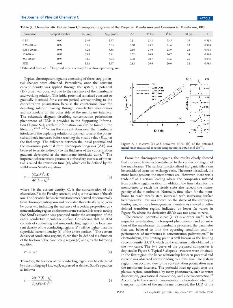
nique for investigating the transport phenomenon and polariza-tion of the membranes. In membrane processes, the parameterthat was believed to limit the operating condition and theperformance of membranes is concentration polarization.29 Inelectrodialysis, this limiting point is well known as the limitingcurrent density (LCD), which can be experimentally obtained bythe i�v curve. The i�v curve of the prepared composites isdepicted in Figure 8. Typical S-shaped i�v curves were obtained.In the first region, the linear relationship between potential andcurrent was observed corresponding to Ohms’ law. The plateauregion then occurred due to the concentration polarization nearthe membrane interface. The potential rises up again after theplateau region, contributed by many phenomena, such as waterdissociation, gravitational convection, and electroconvection.33
According to the classical concentration polarization, when thetransport number of the membrane increased, the LCD of the
Table 3. Characteristic Values from Chronopotentiograms of the Prepared Membranes and Commercial Membrane, FKE
membrane transport number Eo (volt) Emax (volt) ΔE τa (s) τb (s) Δt (s) ε
0 SS 0.90 3.46 3.97 0.51 32.2 23.5 26 0.855
0.2SS-20 nm 0.99 3.25 3.85 0.60 23.2 21.6 23 0.964
0.5SS-20 nm 0.98 3.22 3.88 0.66 24.0 23.9 24 0.998
1SS-20 nm 0.97 3.19 3.91 0.72 24.8 24.7 24 0.998
2SS-20 nm 0.93 3.15 3.93 0.78 28.7 25.6 25 0.946
FKE 0.95 3.13 3.97 0.85 26.6 26.0 24 0.988a Estimated from eq 1. bDeprived experimentally from chronopotentiogram.
Figure 8. i�v curve (a) and derivative dE/di (b) of the obtainedmembranes measured at room temperature in 0.025 mol dm�3.
15131 dx.doi.org/10.1021/jp112157z |J. Phys. Chem. C 2011, 115, 15124–15132
The Journal of Physical Chemistry C ARTICLE
membrane was expected to be lower, as defined by the givenequation.
ilim ¼ jzjCFDδðt̅i � tiÞ ð6Þ
However, as can be noticed from Table 4, the LCD read fromthe i�v curve at the transition of the Ohmic to plateau region didnot follow the trend predicted by the classical concentrationpolarization. This might due to the effect of surface heterogeneityof the composite membranes in the previous discussion. More-over, it has been reported that the LCD can also be affected byseveral factors, including the amount of water content. The jumpin the LCD value of 0.5 wt % SS-20 nmmay be attributed to highwater content that brought about an increase in conductivity anddiffusion permeability of the membranes.14 In addition, thebackward diffusion of the electrolyte solution can also increasethe LCD value of the membranes.The plateau length of the i�v curve is another important
characteristic representing the thickness of the diffusion bound-ary layer (DBL) and the energy required to destroy the DBL. Itwas clear that the plateau length depends on the surfaceheterogeneity of the membranes and the current line distribu-tion. The membrane with more surface heterogeneity has alonger plateau length (ΔE) due to concentration compensationof the low conducting regions that tried to equalize theinterfacial concentration among the regions of differentconductivities.34 It is worth noting that the same trend ofelectrochemical behavior for the composites containing SS-100 nm fillers was also observed.We can thus draw a clear conclusion from the electrochemical
results that a small amount of SS additive not only improved theelectrochemical property of the membranes, but also adjustedthe surface property of the membranes to be more homogeneouswith a higher surface conducting fraction. The peak point wasobserved at around 0.5 wt % loading. With a higher loading of SSfillers, the properties of the composites became worse due to thesignificant agglomeration of the fillers.3.5. NaCl Desalination by ED. The preliminary desalina-
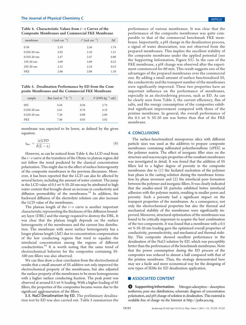
tion test by ED was also carried out. Table 5 summarizes the
performance of various membranes. It was clear that theperformance of the composite membranes was quite com-parable to that of the commercial benchmark FKE mem-brane. Importantly, a pH change in the desalination process,a signal of water dissociation, was not observed from theprepared membranes. This implies the excellent stability ofthe composite membrane under the applied potential (seethe Supporting Information, Figure S3). In the case of theFKE membrane, a pH change was observed after the experi-ment commenced for 60 min. This result suggests one of theadvantages of the prepared membranes over the commercialone. By adding a small amount of surface functionalized SS,the conductivity and the transport number of the membraneswere significantly improved. These two properties have animportant influence on the performance of membranes,especially in an electrodriving process, such as ED. As canbe clearly seen from Table 5, the current efficiency, flux ofsalts, and the energy consumption of the composites exhib-ited significant improvement compared with those of thepristine membrane. In general, the overall performance ofthe 0.5 wt % SS-20 nm was better than that of the FKEmembrane.
4. CONCLUSIONS
The surface-functionalized mesoporous silica with differentparticle sizes was used as the additives to prepare compositemembranes containing sulfonated polyethersulfone (sPES) asthe polymer matrix. The effect of inorganic filler sizes on thestructure andmacroscopic properties of the resultant membraneswas investigated in detail. It was found that the addition of SSfillers led to a higher degree of porosity in the compositemembranes due to (1) the facilated nucleation of the polymerlean phase in the casting solution during the membrane forma-tion by phase inversion and (2) the interfacial pore formationbetween the polymer and inorganic fillers. It was clearly indicatedthat the smaller-sized SS particles exhibited better interfacialadhesion with the polymer matrix, resulting in smaller pores andporosity. Such a porosity had a significant impact on thetransport properties of the membranes. As a consequence, notonly the electrochemical properties but also the thermal andmechanical stability of the membranes were signifciantly im-proved. Moreover, structural optimization of the membranes wasfound to be critically important to acquire the best combinationof the two components. It was found that a membrane with a 0.5wt % SS-20 nm loading gave the optimized overall properties ofconductivity, permselectivity, and mechanical and thermal stabi-lity. This composite showed excellent performance in thedesalination of the NaCl solution by ED, which was perceptiblybetter than the performance of the benchmark membranes. Notethat the power consumption during the ED process of thecomposites was reduced to almost a half compared with that ofthe pristine membrane. Thus, the strategy demonstrated heremay see a facile and more economical way for the designing ofnew types of IEMs for ED desalination application.
’ASSOCIATED CONTENT
bS Supporting Information. Nitrogenadsorption�desorptionisotherms, pore size distributions, schematic diagram of concentrationpolarization, and pHchange of solution in desalination. Thismaterial isavailable free of charge via the Internet at http://pubs.acs.org.
Table 4. Characteristic Values from i�v Curves of theComposite Membranes and Commercial FKE Membrane
membrane i (mA cm�2) i* (mA cm�2) ΔE
0 SS 2.19 2.56 1.74
0.2SS-20 nm 2.03 2.10 1.21
0.5SS-20 nm 2.47 2.47 0.80
1SS-20 nm 2.09 2.09 0.53
2SS-20 nm 2.12 2.24 0.53
FKE 2.06 2.08 1.10
Table 5. Desalination Performance by ED from the Com-posite Membranes and the Commercial FKE Membrane
sample flux (mol m�2 h�1) η P (kWh kg�1 salt)
0SS 4.56 0.56 5.74
0.2SS-20 nm 5.61 0.76 4.19
0.5SS-20 nm 7.38 0.98 2.89
FKE 7.46 0.83 3.92
15132 dx.doi.org/10.1021/jp112157z |J. Phys. Chem. C 2011, 115, 15124–15132
The Journal of Physical Chemistry C ARTICLE
’AUTHOR INFORMATION
Corresponding Author*E-mail: [email protected].
’ACKNOWLEDGMENT
Financial support from the Australian Research Council(through its ARC Centre of Excellence and Discoveryprograms), CSIRO Advanced Membranes for Water TreatmentCluster Project, and Thai Government (through Higher Educa-tional Strategic Scholarship for Frontier Research Network) isgratefully acknowledged. Additional thanks are due to Richardand Robyn Webb for technical support on the SEM and TEMsample preparation and to Frances Stahr, Abijit Shrotri, and Dr.Roland Marchall for their help on the synthesis of mesoporoussilica and surface characterization.
’REFERENCES
(1) Dai, H.; Guan, R.; Li, C.; Liu, J. Solid State Ionics 2007,178, 339–345.(2) Feng, S.; Shang, Y.; Xie, X.; Wang, Y.; Xu, J. J. Membr. Sci. 2009,
335, 13–20.(3) Johnson, B. C.; Yilgor, I.; Tran, C.; Iqbal, M.; Wightman, J. P.;
Lloyd, D. R.; McGrath, J. E. J. Polym. Sci., Polym. Chem. Ed. 1984,22, 721–737.(4) Kerres, J.; Cui, W.; Disson, R.; Neubrand,W. J. Membr. Sci. 1998,
139, 211–225.(5) Kerres, J.; Cui, W.; Reichle, S. J. Polym. Sci., Part A: Polym. Chem.
1996, 34, 2421–2438.(6) Sankir, M.; Bhanu, V. A.; Harrison, W. L.; Ghassemi, H.; Wiles,
K. B.; Glass, T. E.; Brink, A. E.; Brink, M. H.; McGrath, J. E. J. Appl.Polym. Sci. 2006, 100, 4595–4602.(7) Gomes, D.; Marschall, R.; Nunes, S. P.; Wark, M. J. Membr. Sci.
2008, 322, 406–415.(8) Marschall, R.; Bannat, I.; Caro, J.; Wark, M. Microporous
Mesoporous Mater. 2007, 99, 190–196.(9) Marschall, R.; Bannat, I.; Feldhoff, A.; Wang, L.; Lu, G. Q. M.;
Wark, M. Small 2009, 5, 854–859.(10) Wilhelm, M.; Jeske, M.; Marschall, R.; Cavalcanti, W. L.; Tolle,
P.; Kohler, C.; Koch, D.; Frauenheim, T.; Grathwohl, G.; Caro, J.; Wark,M. J. Membr. Sci. 2008, 316, 164–175.(11) Nagarale, R. K.; Gohil, G. S.; Shahi, V. K.; Rangarajan, R.
Macromolecules 2004, 37, 10023–10030.(12) Nagarale, R. K.; Gohil, G. S.; Shahi, V. K.; Rangarajan, R.
J. Colloid Interface Sci. 2005, 287, 198–206.(13) Nagarale, R. K.; Shahi, V. K.; Rangarajan, R. J. Membr. Sci. 2005,
284, 37–44.(14) Berezina, N. P.; Kononenko, N. A.; Dyomina, O. A.; Gnusin,
N. P. Adv. Colloid Interface Sci. 2008, 139, 3–28.(15) Klaysom, C.; Marschall, R.; Moon, S.-H.; Ladewig, B. P.; Lu,
G. Q. M.; Wang, L. J. Mater. Chem. 2010, 21, 7401.(16) Klaysom, C.; Moon, S.-H.; Ladewig, B. P.; Lu, G. Q. M.; Wang,
L. J. Membr. Sci. 2011, 371, 37–44.(17) Chazeau, L.; Gauthier, C.; Vigier, G.; Cavaille, J. Y. InHandbook
of Organic-Inorganic Hybrid Materials and Nanocomposites; Nalwa, H. S.,Ed.; American Scientific Publishers: Stevenson Ranch, CA, 2003; Vol. 2,pp 63�111.(18) Yokoi, T.; Karouji, T.; Ohta, S.; Kondo, J. N.; Tatsumi, T.Chem.
Mater. 2010, 22, 3900–3908.(19) Tsubokawa, N.; Yoshikawa, S. J. Polym. Sci., Part A: Polym.
Chem. 1995, 33, 581–586.(20) Klaysom, C.; Marschall, R.; Ladewig, B. P.; Lu, G. Q. M.; Wang,
L. J. Mater. Chem. 2010, 20, 4669–4674.(21) Klaysom, C.; Ladewig, B. P.; Lu, G. Q. M.; Wang, L. J. Membr.
Sci. 2010, 368, 48–53.
(22) Nagarale, R. K.; Gohil, G. S.; Shahi, V. K. Adv. Colloid InterfaceSci. 2006, 119, 97–130.
(23) Shahi, V. K. Solid State Ionics 2007, 117, 3395–3404.(24) Elatar, A.; Elmidaoui, A.; Pismenskaia, N.; Gavach, C.; Pourcelly,
G. J. Membr. Sci. 1998, 143, 249–261.(25) Volodin, E.; Pismenskaia, N.; Nikonenko, V.; Larchet, C.;
Pourcelly, G. J. Colloid Interface Sci. 2005, 285, 247–258.(26) Larchet, C.; Nouri, S.; Auclair, B.; Dammark, L.; Nikonenko, V.
Adv. Colloid Interface Sci. 2008, 139, 45–61.(27) Choi, J.-H.; Kim, S.-H.; Moon, S.-H. J. Colloid Interface Sci.
2001, 241, 120–126.(28) Vyas, P. V.; Ray, P.; Adhikary, S. K.; Shah, B. G.; Rangarajan, R.
J. Colloid Interface Sci. 2003, 257, 127–134.(29) Balster, J.; Krupenko, O.; Punt, I.; Stamatialis, D. F.; Wessling,
M. J. Membr. Sci. 2005, 263, 137–145.(30) Balster, J.; Yildirim, M. H.; Stamatialis, D. F.; Ibanez, R.;
Lammertink, R. G. H.; Jordan, V.; Wessling, M. J. Phys. Chem. B 2007,111, 2152–2165.
(31) Krol, J. J.; Wessling, H.; Strathmann, H. J. Membr. Sci. 1999,162, 145–154.
(32) Tanaka, Y. J. Membr. Sci. 2004, 244, 1–16.(33) Nikonenko, V. V.; Pismenskaia, N. D.; Belova, E. I.; Sistat, P.;
Huguet, P.; Pourcelly, G.; Larchet, C. Adv. Colloid Interface Sci. 2010,160, 101.
(34) Pismenskaya, N.; Sistat, P.; Huguet, P.; Nikonenko, V.;Pourcelly, G. J. Membr. Sci. 2004, 228, 65–76.