Embed Size (px)
Citation preview

The In-Silico Lab-on-a-Chip:Petascale and High-Throughput Simulations of
Microfluidics at Cell Resolution
Diego Rossinelli1, Yu-Hang Tang2,∗, Kirill Lykov3,∗, Dmitry Alexeev1,
Massimo Bernaschi4, Panagiotis Hadjidoukas1, Mauro Bisson5, Wayne Joubert6, Christian Conti1,
George Karniadakis2, Massimiliano Fatica5, Igor Pivkin3, Petros Koumoutsakos1
1ETH Zürich, Switzerland, 2Brown University, U.S.A., 3USI, Switzerland,4CNR, Italy, 5NVIDIA Corporation 6Oak Ridge National Laboratory (ORNL), U.S.A.
∗Equally credited authors
ABSTRACTWe present simulations of blood and cancer cell separationin complex microfluidic channels with subcellular resolu-tion, demonstrating unprecedented time to solution, per-forming at 65.5% of the available 39.4 PetaInstructions/s inthe 18, 688 nodes of the Titan supercomputer.
These simulations outperform by one to three orders ofmagnitude the current state of the art in terms of numbersof simulated cells and computational elements. The com-putational setup emulates the conditions and the geometriccomplexity of microfluidic experiments and our results re-produce the experimental findings. These simulations pro-vide sub-micron resolution while accessing time scales rele-vant to engineering designs.
We demonstrate an improvement of up to 45X over com-peting state-of-the-art solvers, thus establishing the frontiersof simulations by particle based methods. Our simulationsredefine the role of computational science for the develop-ment of microfluidics – a technology that is becoming asimportant to medicine as integrated circuits have been tocomputers.
KeywordsSupercomputing, time-to-solution, peak performance, irreg-ular codes, dissipative particle dynamics, microfluidics sim-ulations, blood analytics, circulating tumor cells
1. INTRODUCTIONThe quest towards miniaturisation of devices capable of
handling fluids and biological matter at a molecular level isrevolutionising medicine and pharmaceutical research. Mi-
ACM acknowledges that this contribution was authored or co-authored by an em-ployee, or contractor of the national government. As such, the Government retainsa nonexclusive, royalty-free right to publish or reproduce this article, or to allow oth-ers to do so, for Government purposes only. Permission to make digital or hard copiesfor personal or classroom use is granted. Copies must bear this notice and the full ci-tation on the first page. Copyrights for components of this work owned by others thanACM must be honored. To copy otherwise, distribute, republish, or post, requires priorspecific permission and/or a fee. Request permissions from [email protected].
SC ’15, November 15-20, 2015, Austin, TX, USAc© 2015 ACM. ISBN 978-1-4503-3723-6/15/11. . . $15.00
DOI: http://dx.doi.org/10.1145/2807591.2807677
crofluidic systems, such as lab-on-a-chip, transport and ma-nipulate nanoliter quantities of fluids and cells to enable pre-cise analysis and large-scale automation for important bio-chemical processes. By benefiting from an economy of scales,microfluidics is advancing technologies ranging from clinicaldiagnostics and cancer detection to regenerative medicineand proteomics [67, 61].
Microfluidic devices exploit the functional properties offluids confined in microscopic channels to perform tasks suchas blood separation, detection of circulating tumor cells, andmolecular recognition with high sensitivity and specificity[59, 10]. However, the acquisition of information of the fluidmicro-rheology, including phenomena such as cell merging,lysis [45] and biochemical signaling [69] remains a formidabletask [52]. Without such information, the unique, and oftenunexpected, properties of fluids at the micro-scale can bea hindrance for new designs while complex prototypes maybe impossible to manufacture at an economy of scales. Fastturnaround times for design are essential for the evolvingtechnologies (3D printing, liquid biopsies, organ-on-a-chip)of microfluidic chips that can assist medical analysis anddrug development [57, 43, 12]. Predictive simulations arebecoming an invaluable tool in accelerating the design cyclefor microfluidics [33].
Today, the majority of simulations for microfluidic sys-tems employs continuum models. Grid based and BoundaryIntegral solvers of the linear viscous Stokes equations canhandle the geometries of the microfluidic channels but theyhave limited capabilities in resolving essential sub-micronflow biophysics [18]. Continuum models cannot be read-ily extended to capture cell topological changes, membranetransport and electrochemical interactions between the chan-nel and the fluid constituents. Such processes are essentialfor important microfluidic applications ranging from drugdelivery and immunoassays [10] to micro-robotics for non-invasive surgery [46].
Mesoscale models, such as Lattice Boltzmann (LB) [9] andStochastic Particle Methods (SPM) ([20, 34] and referencestherein), use discrete particles to represent flows in microflu-idic channels. They overcome the limiting assumptions ofcontinuum models at the expense of requiring larger num-bers of computational elements to resolve sub-micron scales

and processes. LB methods have been ported to supercom-puting architectures to simulate blood flows [6] and proteincrowding phenomena [7]. The LB kernel is memory inten-sive and although very amenable to parallel processing, ithardly achieves a significant percentage of the peak perfor-mance on most modern computing platforms [8]. Similar tocontinuum models, LB approaches need the a priori speci-fication of the diffusion constant. Moreover, their accuracydecreases rapidly and their computational cost increases asthe Reynolds number approaches zero, thus limiting theirapplicability to microfluidics.
Dissipative Particle Dynamics (DPD) [27] is a SPM thatbridges the gap between Molecular Dynamics and NavierStokes equations [13]. It has been used extensively to modelcomplex fluids such as colloidal suspensions, emulsions andpolymers [26] and has become a key method for the studyof the blood microrheology [55, 70]. DPD resolves cells at asub-micron scale to simulate microfluidic [60] and drug de-livery systems [44], reaching time scales that have been pre-viously accessible only to Navier-Stokes solvers [18]. Stateof the art DPD solvers are based on extensions of MolecularDynamics (MD) software packages such as LAMMPS [54]and HOOMD-Blue [3] targeting both CPU-only and GPU-accelerated supercomputers. The DPD is a consistent coarsegraining of Molecular Dynamics (MD) [25], accessing contin-uum time scales with sub-micron resolution. However, whileMD and DPD share similarities as particle based solvers,the physics represented by their interaction potentials havesignificant differences [34]. These differences translate into anumber of challenges for the effective parallelisation of DPD.As an example, in DPD the overall exposed instruction-levelparallelism (ILP) is higher than in MD and it can be ex-tracted by the current CPU and GPU microarchitectures.
GPU-accelerated supercomputers exhibit significant dif-ferences from those based solely on CPUs in terms of through-put and latencies of the different instructions. On the CPU,integer instructions are usually the fastest, while double pre-cision (DP) instructions are among the most expensive andsingle precision (SP) instructions have twice the throughputof the DP instructions. In contrast, on the GPUs of currentsupercomputers, SP instructions are the fastest. These SPinstructions take just one cycle and the throughput imbal-ance between SP and DP instructions is 3:1, instead of themore common 2:1. Furthermore, on GPUs, many integerinstructions are as expensive as the DP ones.
These imbalances indicate that GPUs in current super-computer have been designed to process SP instructionsmore efficiently than any other instructions. This leads torather counter-intuitive observations regarding the “tradi-tional” performance metrics in supercomputing. For exam-ple, a compute kernel featuring exclusively DP instructionsthat is capable of achieving 100% of the nominal DP peakperformance, is actually performing at 1/3 of the potentialcompute power offered by the GPU. This challenges metricsbased on DP, since the performance achieved by such a DPkernel is arguably 33% of the nominal throughput. Hence, inthis work we use the vector instruction per second [I/s] andinstruction per cycle [I/c] (or IPC) as performance metrics.
We present a high-throughput software for DPD simula-tions based on thoroughly optimized kernels for GPUs. Ourcode simulates for the first time blood flow and circulatingtumor cells in realistic geometries of complex microfluidicchannels at sub-micron resolution and times that are rele-
vant to clinical applications. The software maps effectivelythe DPD method to the 18,688 GPUs of the Titan super-computer by overcoming the following challenges:
• The irregular computational patterns inherent to DPDare not readily data-parallel. These irregularities pre-vent the simulations from reaching high fractions ofthe peak performance.
• DPD involves particle interactions that require hun-dreds of instructions. This is an order of magnitudemore instructions than Lennard-Jones interactions inMD simulations.
• DPD accesses time scales that are several orders ofmagnitude larger than those accessible by MD. At thesame time, in DPD simulations, the particle neigh-borhood changes practically at each time step. Henceduring the evaluation of the interactions around 80% ofthe instructions are spent in identifying possible neigh-bors.
• The DPD thermostat (dissipative and random forces)is the most expensive part in the computation of DPDinteractions. It consists mostly of integer instructionswhich do not map efficiently on current GPUs.
• DPD implies challenging inter-node communication pat-terns. It requires non-trivial CPU-GPU cooperationsto pack/unpack messages, and hundreds of MPI point-to-point communications per rank and time step. Mes-sage sizes are not known a-priori, preventing a straight-forward Computation/Transfer (C/T) overlap.
The present DPD solver effectively exploits the capabili-ties of the Titan supercomputer and allows for simulationsat spatiotemporal scales that are impossible for MD, whilemaintaining molecular level details that are inaccessible tocontinuum solvers. The goal of the present effort is to ac-celerate the design and testing of microfluidics devices byan order of magnitude while resolving phenomena at sub-micron scales. The target time-to-solution for simulationsof a full microfluidic device is in the range of 2-6 hours, im-plying 106 − 107 iterations. This goal is met by the presentcode.
Contributions of this paper.The present work redefines the frontiers of simulations for
microfluidic devices by improving by two orders of magni-tude the geometrical detail as well as the number of cellspreviously resolved using continuum solvers. We present atool which uses the most accurate and experimentally vali-dated [16, 14], deformable models for red blood cells (RBC),white blood cells (WBC) and circulating tumor cells (CTC)and can perform, for the first time in-silico, cell separationin microfluidic devices that have been previously tested onlyin-vitro.
Our software outperforms state of the art DPD solvers,deployed on GPU based supercomputers, by up to 45X. Thesoftware enables unprecedented simulations of cell separa-tion in two different microfluidic devices [32, 42] with sub-micron resolution. In addition to the unprecedented geo-metric complexity afforded by our code, these simulationsprovide a three orders of magnitude improvement over thecurrent state of the art in terms of numbers of RBCs andtime-to-solution.

The paper is structured as follows: in Section 2 we give abrief overview of the current state of the art for DPD soft-ware and simulations related to microfluidics and in Section3 we introduce the mathematical framework for DPD. Wedescribe the computing platforms we used for our simula-tions in Section 4 while in Section 5 and Section 6 we reportdetails of the design and development of the present soft-ware. In Section 7 we present the results of our simulations.Finally, we present our performance results in Section 8 andprovide conclusions in Section 9.
2. CURRENT STATE OF THE ART
DPD on supercomputers.The computational complexity of DPD has hindered its
use for large-scale simulations for time scales relevant to en-gineering designs. Accurate DPD models require at least500 elements to represent the dynamics of a RBC [53], hencefor simulating RBC separation in a blood sample of 1mm3
with a hematocrit of 45% over 109 particles are required.To the best of our knowledge, there has never been a sim-ulation of blood flow in complex 3D microfluidics chip withsubcellular-level resolution, reaching spatiotemporal scales ofrealistic devices as shown in this study.
Currently, software for DPD deployed on supercomputersis based on extensions of code originally developed for MD,such as LAMMPS [54] and HOOMD-Blue [3]. LAMMPS(Large-Scale Atomic/Molecular Massively Parallel Simula-tor) was originally developed for MD simulations on dis-tributed memory architectures with CPUs featuring SingleInstruction Multiple Data (SIMD) [54]. LAMMPS is one ofthe six projects selected from the Center for Accelerated Ap-plication Readiness by the Oak Ridge Leadership Comput-ing Facility (OLCF) and has been extended to perform DPDsimulations on Titan [47]. The largest LAMMPS/DPD sim-ulation reported 32-256K particles per node. They sim-ulated 256 Million particles on 1024 Titan nodes with athroughput of 5 - 7.6 Million Particles per second [MP/s][47].We demonstrate that our implementation of DPD outper-forms this Titan optimized version of LAMMPS by up to45X.
HOOMD-Blue [3] aims at taking advantage of the com-pute capabilities offered by Single Instruction Multiple Thread(SIMT) architectures [19] and has also been extended to sup-port DPD simulations [51]. The fastest HOOMD-Blue/DPDsimulation reported throughput 1.85 [MP/s] on a GeForceGTX 480 [51], which, projected on a Titan node, wouldcorrespond to 6.7 [MP/s]. However, in its current version,HOOMD-Blue is not capable of large-scale simulations usingmore than 124 Million particles (see also the PerformanceSection).
The largest and fastest DPD simulations so far, had beenperformed with USER-MESO, a LAMMPS fork by Tangand Karniadakis [62]. These simulations employed 1 Billionparticles on 1024 Titan nodes with reported throughput of10− 30 [MP/s] per node, for the simulation of spontaneousvesicle formation.
Blood flow simulations.The first large-scale simulations of RBCs were performed
by Rahimian et al. [56]. They used a boundary integralsolution of the continuum linear Stokes equation to simu-
late 262 Million RBCs, each discretized with 84 vertices,totaling 88 billion unknowns. In terms of throughput, theymeasured about 290 Million unknowns/s, leading to a theo-retical throughput of about 2.6 Billion RBC unknowns/s onTitan.
Lattice Boltzmann simulations of the blood flow into acoronary arteries network employed 450 Million non-deformableRBCs observed a throughput of 540 Million unknowns/sand 1 PFLOP/s in double precision on Tsubame [6]. Xuet al. [68] performed blood flow simulations with 50,000RBCs at the exceptional resolution of 3,300 vertices perRBC. Large-scale rheological simulations, albeit with non-deforming RBCs, have reached 4 Millions RBCs [31].
The first DPD simulations of RBCs transiting in smallmicrofluidics channels [55] predicted the strong dependencybetween temperature and the dynamics of a RBC due tochanges in the membrane viscosity. Methodological improve-ments and increased resolution enabled DPD to predict, forthe first time, the blood viscosity as a function of the shearrate and hematocrit level [16]. These simulations involvedabout 200 RBCs and provided insight on the magnitude ofthe adhesive forces acting between cells. In the last fewyears the use of DPD has burgeoned for the study of cel-lular systems and in particular for the study blood flow inmicrofluidic devices. These studies include the first evercombination of experiments and DPD simulations to exam-ine large deformations of RBCs in microfluidic devices [55]and the identification of the governing mechanisms for in-creased blood viscosity in sickle cell anemia [37].
CTC models and microfluidics devices.The detection of CTCs in the blood is one of the most
potent methods for the early diagnosis of cancer [2] and akey target of liquid biopsies [49]. However, with 1 CTCpresent for every 109 RBCs, this detection is equivalent tofinding a ”needle in a flowing haystack”. This challenge hasled to a wealth of activity in developing microfluidic devicesfor high throughput cell separation. At the same time, ourunderstanding of flow mediated interactions between CTCs,blood and microfluidic devices is hindered by the lack of de-tailed experimental information [35]. The rational design ofsuch devices based on simulations is at its infancy. The Vol-ume of Fluid method was employed to model a CTC passingthrough a narrow channel [70] while a CTC membrane modelbased on the LB approximation investigated microfluidicsdevices exerting large cell deformations [24]. Other studiesinclude flows of suspended RBCs and WBCs past an arrayof displaced circular obstacles [65], DPD simulations of thebead assay problem [60] and in-vitro and in-silico studies ofa passive hydrodynamic cell sorter for leukocyte enrichment[11].
The CTC-iChip [32], arguably one of the most effectivemicrofluidic device to date to separate CTCs from RBCswas designed with the assistance of a Finite Element solverof the continuum Stokes equations. The simulations wereused to investigated the shape of a simplified array of ob-stacles that lead to cell separation by exploiting the conceptof the Deterministic Lateral Displacement [28]. The result-ing optimal “egg-looking” shape has been used as a buildingblock in the first compartment of the CTC-iChip microflu-idics device. This compartment, in its full geometric com-plexity, is one of the devices studied in the present work.

3. NUMERICAL METHODSThe method of Dissipative Particle Dynamics (DPD) [27,
22] employs discrete particles interacting through pairwiseforces. The force Fi acting on particle i consists of threeadditive parts:
Fi =
N∑j 6=i
(FCij + FD
ij + FRij) , i = 1, ..., N (1)
which are non-zero within a cutoff radius (Rc = 1). The con-servative force FC
ij is a soft repulsion force, acting along the
vector between particles i and j. The dissipative force FDij
depends on the relative velocity of the particles and modelsfriction effects, while the random force FR
ij represents the ef-fect of the suppressed degrees of freedom in the form of ther-mal fluctuations. The parameters of the random and dissi-pative forces are related through a fluctuation-dissipationtheorem [13]. The time evolution of this N-body problem isdescribed by Newton’s equations of motion and a leap-frogalgorithm is used to advance the system in time.
We emphasize that, unlike most mesoscale particle meth-ods, the DPD is rigorously derived from MD through theMori-Zwanzig coarse-graining procedure [25]. DPD modelsexplicitly the hydrodynamics forces in the solvent and en-tails an accurate kinematic description of the flow [13, 17].The complex interaction between fluids, cells and walls, aremodeled with appropriate DPD parameters. DPD is an in-herently multiscale particle method, well suited to simulat-ing microfluidics devices allowing for sub-micron resolutionand accessing continuum time scales. The computationalstages involved in one time step of a DPD flow simulationinvolving suspended RBCs and CTCs is shown in Figure 2.
Walls and microscale geometries.The boundaries of the microfluidic channels are discretized
by first equilibrating a homogeneous DPD fluid and thenfreezing particles which are inside the wall geometry. Thechannel wall geometry is represented implicitly by a SignedDistance Function (SDF) allowing for domains with veryhigh geometric complexity. Boundary conditions are en-forced through DPD interactions between wall and solventparticles and a bounce-back mechanism after the update ofthe particle positions [63].
Cell Modeling.The RBC membrane has two main components: an elas-
tic spectrin network and an incompressible lipid bilayer.When relaxed, the membrane assumes a biconcave shapewith a diameter of D = 7.6µm (for humans). In this work,the RBC membrane is modeled as a mesoscopic viscoelasticmembrane. The model adopted here was proposed by Li etal. [39] and later extended by viscous membrane forces [48].This model is intensively used to study the mechanical prop-erties of individual RBCs [55, 38, 50] as well as blood flowsin various conditions[37, 16, 15].
The RBC membrane is discretized on a mesh as depictedin Figure 1. There are three types of bonded forces on eachvertex of the mesh: pairwise interactions for all incidentedges (black edge, Fbond), angle forces for all incident tri-angles (red triangle, Ftriangle), dihedral forces for all pairsof adjacent incident triangles (orange triangles, Fdihedral1),and dihedral forces for pairs of adjacent triangles where onetriangle is incident to the vertex (yellow triangles, Fdihedral2)
[14]. The number of vertices per membrane should be chosen
Figure 1: An RBC membrane model discretized by 500 ver-tices (left) and the bonded force types acting on it (right).
according to the required level of details. For the present nu-merical investigations we consider a discretization involving500 vertices.
The modeling of WBCs and CTCs employs a recently pro-posed, experimentally validated, extension of a RBC model[15]. We remark that there is a wide variety of CTC typeswith disparate diameters ranging from 10µm to 24µm andwith significantly different mechanical properties [23, 29, 40].Here we consider MCF-7 breast cancer cells with a diame-ter of 14µm by using 2484 vertices as well as RT4 bladdercancer cells with diameter 20µm and 5220 vertices.
Redistribute particles among subdomains
Build cell lists
Remote solvent interactions
Solvent forces
RBCs/CTCs internal forces
Wall forces: solvent,RBCs/CTCs
Compute f
Update v, x
RSI: solvent, RBCs/CTCs
Exchange halo solvent
FSI: remote RBCs/CTCswith local solvent
Remote forces
Compute intensive
Communication
Memory intensive
Time integration
Collision handling with walls
Exchange RBCs/CTCs
Figure 2: The computational stages involved in one timestep of a DPD simulation involving suspended RBCs andCTCs.
4. TARGET PLATFORMSThe present simulation software was developed target-
ing two supercomputers: Titan, the fastest supercomputeravailable at the present time, from Oak Ridge National Lab-oratory; and Piz Daint, the fastest supercomputer in Eu-rope, from the Swiss National Supercomputing Centre (CSCS).These supercomputers have a nominal aggregate CPU-GPUpeak rate of 39 and 12 normalized1 PetaInstructions/s re-spectively (see Table 1).
The per-node performance for Titan and Piz Daint is pri-marily attributed to the NVIDIA K20X GPU, a SIMT archi-tecture which dispatches the computation to its 14 Stream-ing Multiprocessors (SMX), each containing 192 CUDA cores.
1#nodes × (#CPU cores × CPU-freq × SIMD-width × 2[I/c] + 0.732 · 109 [Hz] × 14 SMX × 192 CUDA cores × 1[I/c]).

Table 1: Target platforms.
Titan Piz DaintModel Cray XK7 Cray XC30
Host/CPU Opteron 6274 Xeon E5-2670Device/GPU K20X K20X
Nodes 18,688 5,272Inter-node bw. [GB/s] 2.5 8.1
Aggregate GPU [I/s] 3.7× 10¹⁶ 1.0× 10¹⁶
Aggregate CPU-GPU [I/s] 3.9× 10¹⁶ 1.2× 10¹⁶
Type Model [GB] [I/s] [I/c]
GPU K20X 6 2.0× 10¹² 2.7× 10³
CPU Opteron 6274 32 0.14× 10¹² 64CPU Xeon E5-2670 32 0.33× 10¹² 128
Each CUDA core is capable of performing 1 [SP FLOP/c].The K20X GPU is based on the NVIDIA Kepler microar-chitecture, CUDA compute capability 3.5, featuring 6 GBof device memory.
Each SMX can schedule the work of 16 CUDA blocks con-currently, fragmented into warps of 32 threads. At every cy-cle, the four per-SMX schedulers pick four eligible warps outof a pool of 64, and fetch up to two instructions each, totalinga maximum of six warp-level instructions per SMX. Becauseof the dual-issue nature of the schedulers, the compute ker-nel must expose enough Instruction Level Parallelism (ILP)to reach the peak throughput. To maximize the numberof eligible warps, and thus maximize the available work percycle, each thread should require no more than 32 registers.The measured peak device bandwidth is about 180 [GB/s]and the measured peak throughput 1.8 · 1012 [I/s]. The bestmeasured per-warp throughput was 5.5 [I/c] as opposed tothe nominal one of 6 [I/c].
The K20X exhibits a 3-to-1 throughput imbalance of DPversus SP instructions. We remark that in terms of through-put, integer instructions are 1.2X - 6X slower than SP in-structions. These observations suggest that the K20X wasdesigned to aggressively process SP instructions, over anyother instructions.
SIMT advantages for DPD.The irregular computational patterns of DPD exhibit a
massively parallel, fine-grained heterogeneous workload. Thisheterogeneity leads to a number of control flow exceptionsthat is excessively large to be effectively handled explicitlyon SIMD architectures. Even if masking instructions allevi-ate this problem, the burden of dealing with masks inadver-tently impairs both coding productivity and kernel perfor-mance.
Furthermore, compared to SIMD architectures, SIMT pro-vides a number of unmatched advantages, starting with theability to discover vectorization at runtime. The detec-tion of exceptional cases in the computation (such as databoundaries, misalignment, etc.) is delegated to the hard-ware. This dramatically increases the readability of the codeand the productivity of the programmer. A second advan-tage is the ability of scattering/gathering data to/from arbi-trary locations in the shared memory. These operations en-able effectively to “homogenize” the irregular DPD workloadinto data-parallel-ready computation. Finally, with controlflow instructions at warp-level, the cooperation among the
threads within a warp can be dynamically adjusted to theavailable workload so as to minimize the overhead or theintra-warp imbalance.
5. DESIGNThe complexity of flows involving RBCs and CTCs in mi-
croscale geometries impacts adversely the performance ofthe simulations. In turn, this poses significant challenges inmapping effectively the computational patterns onto GPUaccelerated supercomputers.
A number of design choices have been made in order tosignificantly improve the performance:• Computation is performed in single precision• Avoid global particle ids• Neighbor lists are not stored in off-chip memory• Fast Random Number Generator (RNG)• Each kernel operates at most on two particle types
Time steps in DPD simulations are usually between 10−3-10−2, while the magnitude of the forces rarely exceed 102.In these units it takes hundreds of thousands of time stepsto resolve one cycle of the tumbling of a single RBC. Thissuggests that the single precision mantissa is large enough(106) to capture the difference in the orders of magnitudesacross the unknowns of the simulation. This observation ren-ders the vast majority of the DPD computational patternsamenable for SP computation, which in turn accelerates upto 3X the time-to-solution.
A global particle id may simplify the management anddiagnostics of the simulation. However, it represents anunnecessary overhead when involved in the computation ofthe forces or the dynamic creation of new solvent particlesas well as new RBCs or CTCs. Similarly, the overhead ofkeeping a per-particle neighbor list is hardly amortized if weconsider that high flow strain rates impose a complete recon-struction of the neighbor lists at every time step. Further-more, the cost of the DPD interactions can be straightfor-wardly hidden by the irregular work required for producingthe neighbor list.
The random force of the DPD interactions requires a com-putationally efficient random number generator (RNG). Someof the algorithmically most efficient RNGs are those basedon the Tiny Encryption Algorithms (TEA) [66], such as theSARU algorithm [1]. For the K20X, a performance issue ofthe TEA-based RNGs is that they mostly feature integerinstructions. As described below, we have developed a novelRNG based on the Logistic map which features exclusivelyFMA instructions.
In order to achieve high performance in the compute ker-nels we restrain them to operate concurrently on just twoparticle types. This enables us to apply type-specific opti-mizations when computing the interactions.
Most of the workload imbalance is expected to come fromthe irregularity of the microscale geometry. Since the ge-ometry is known a priori, we introduce a pre-processingstep to provide an optimized rank-to-node mapping to theapplication-level placement scheduler. The reordering as-signs an heterogeneous number of MPI tasks to each nodeso as to equalize the per-node workload.
Memory layout.The domain of the present simulations is decomposed in
a cartesian fashion in parts of equal size and shape. Weemploy an Array-of-Structure (AoS) format that provides us

Figure 3: The separation of the temporal scales betweensolvent and cells allows us to consider multi-timesteps algo-rithms [58].
with the best tradeoff between spatial locality and effectivememory access for DPD simulations. This layout is alsoreasonably efficient when packing/unpacking MPI messagescontaining particle information.
The representation of the wall geometry is entirely localto its respective subdomain. Once created the wall data areimmutable objects. Hence, after the wall creation the asso-ciated information can be exchanged only once across neigh-boring MPI tasks, in a fashion similar to a halo exchange.This renders the handling of collisions between walls andDPD fluid as well as cells entirely local to each MPI task.
Cluster-level optimizations.The design choices at this level aim to minimize the amount
of communication and achieve maximum C/T-overlap. Forthe computation of the forces within the solvent, C/T-overlapis achieved by exchanging messages of a predefined size. Af-ter packing the messages on the GPU, each MPI task per-forms non-blocking point-to-point communication with its26 surrounding tasks while computing the local DPD forces.Since the force evaluation takes 1 − 10 ms and the com-munication takes 0.01 − 0.1 ms, we expect the messages toarrive before the local computation has been completed. Wethen compute the inter-node DPD interactions by fetchingdirectly the MPI messages from the GPU using zero-copymemory.
In certain cases the number of solvent particles to be com-municated exceeds what can be held by a single message.These cases are safely detected and handled by sending a sec-ond message in a blocking fashion, whereas the C/T-overlapmay be decreased for that timestep.
Node-level optimizations.At node-level, the simulation code employs multiple CUDA
streams to coordinate the execution of the different computekernels. We rely both on the operating system and MPS toeffectively run multiple MPI tasks with heterogeneous work-loads on the node. We exploit the separation of the tempo-ral scales between the solvent and the RBC membrane, sincethe viscosity of the latter is 10− 100 times larger. Our timescales separation approach is similar to the one discussed bySchlick [58]. Since the computation of the membrane forcesis relatively inexpensive (1%−5% of the total workload), weare able to increase the DPD time step by a factor of 10 andupdating just the cells at substeps of 1/10 of a time step. Asillustrated in Figure 3, for a coarse time step, we first cal-culate the total external forces (from the solvent and wallparticles) on the cells, and then evolve the cells by adding
Figure 4: The workload of a cell is mapped to a warp so asto decrease warp divergence and work imbalance. Firstly,the particle count of the surrounding cells is fetched, thenthe prefix sum is computed.
internal forces of the cells to the external ones and integrat-ing at finer time steps. These finer steps are entirely localto the node and do not require any MPI communication.
GPU-level optimizations.The most time consuming kernels are the ones computing
the interaction forces, namely: DPD, FSI and walls. TheDPD kernel computes the DPD interactions within each sub-domain. The FSI kernel computes the interactions betweenthe solvent particles and the particles representing the sus-pended cells. The Wall kernel is responsible for computingthe interactions between the DPD particles and the wallparticles. These kernels take advantage of Newton’s 3rd lawand work cooperatively on the cell-lists, minimizing warpdivergence and maximizing temporal and spatial locality.
Figure 4 depicts how the computation of a cell list entryis mapped to a warp. A reindexing of the workload is per-formed through the shared memory. The reindexing consistsof a prefix sum of the cell count of the 27 surrounding cells.The result is then shared across the CUDA threads, whichare organized into an interaction matrix (16x2 in the case ofFigure 4). For every thread, the corresponding source par-ticle is found by performing a trinary search of the prefixsum.
All compute-bound kernels were subject to a ”floatization”process, where integer instructions are replaced by FP in-structions. This is implemented by reinterpreting integervariables as denormalized SP numbers and perform SP op-erations at full precision. The correctness of such operationsis guaranteed by using inline PTX assemblies with explicitrounding and flushing modifiers.
We propose a novel stateless RNG that consumes mostlyFMA instructions by using the Logistic map [21, 64], a non-linear chaotic recurrence relation defined for real numbers.The series Xn+1 = 4Xn(1 − Xn), Xn ∈ [0, 1] maps theinterval [0, 1] onto itself with a probability density function
p(x) =(π√x(1− x)
)−1
, x ∈ [0, 1].
The recurrence relation is chaotic and hence generates un-predictable sequences after sufficiently large number of iter-ations. The distribution is symmetric on [0, 1] with a meanof 1
2and a variance of 1
8. A random number sequence of zero
mean and unit variance can thus be obtained by shifting andscaling Xn.
We introduce Algorithm 1 for generating a unique se-quence of random numbers for each pair of interacting par-ticles. The algorithm combines a time-dependent globalseed with particle indices into pairwise-unique seed values,which then get crunched through the Logistic pipeline for

further randomization. A serial high quality RNG, in ourcase KISS [41], generates the global seed since only one valueis used for each time step.
Algorithm 1 Logistic based parallel RNG for DPD.
// k = k(t) is a time-dependent global random number sequence
// G is the golden ratio√
5−12 ≈ 0.618 · · ·
// S is another irrational number√2− 1 ≈ 0.414 · · ·
function Mean0Var1(i,j,k)// Low-discrepancy numberu ← Min(i,j)v ← Max(i,j)pij ← Mod(u×G + v × S,1)y ← k − pij
// Pass through Logistic mapfor N rounds do
y ← 4y(1− y)end for
// Normalizez ← Normalize(y)return z
end function
The generator passes 158 out of 160 tests in BigCrush[36] with 18 Logistic iterations and achieves zero mutualinformation across sequences for different particle pairs.
6. SOFTWAREThe development of the present software2 started on July
2014. Four main developers were involved for approximately24 man-months. During this time our team followed the Ex-treme Programming principles developed by Kent Beck [5],including small releases, continuous integration, and test-driven development. The software is written in CUDA andMPI; it targets NVIDIA GPUs with compute capability 3.5or higher. The resulting software consists of about 80,000lines of code. Approximately 10,000 lines of code involveObject-Oriented programming and carry out the CPU-GPUcoordination and MPI communication. The cell membranemodel code takes about 15,000 lines of code, the code forthe optimized DPD interactions takes about 5,000 lines ofcode and makes heavy use of PTX intrinsics. The remain-ing 50,000 lines of code consist of unit tests and proof-of-concepts.
The software implements Lustre-aware parallel I/O fordata dumps, whose formats are compliant to ParaView [4].The mesh data generated by the present simulations wasrendered with the Mitsuba Renderer [30].
7. LARGE-SCALE SIMULATIONSWe demonstrate the capabilities of our software to per-
form simulations of cells separation in complex geometries,under different conditions by examining two devices: (I) theCTC-iChip [32] and (II) the Funnel Ratchets [42].
Device I: CTC-iChip.In this work as a proof of the capabilities of our software
we simulate flows of RBCs and CTCs in the CTC-iChip [32].The CTC-iChip is a microfluidics system, with two mod-ules, that has shown great potential for blood separationand capture of CTCs. The one-to-one geometric correspon-
2 https://github.com/rossinelli/uDeviceX
Figure 5: Device I: Simulation of the first module of theCTC-iChip with 200,000 RBCs spiked with 1 CTC (not vis-ible - see also Figure 6, top).
dence between the CTC-iChip and the geometries studiedherein, allows us to confirm these features.
In this work we focus on the first compartment of the de-vice (CTC-iChip1), which separates CTCs and WBCs fromRBCs by taking advantage of the deterministic lateral dis-placement effect [28]. The size of the CTC-iChip1 deviceis 150µm tall, ∼ 750µm wide and at least 3.8 mm long.Pillared obstacles form a microarray of 13 rows and at least118 posts along the module, as illustrated in Figure 6 (top).The cross section of the posts is “egg”-shaped of size 17µmalong the X-direction and 24µm in the Y-direction. Thismicroarray is characterized by a gap of 32µm between therows, 15µm between the columns and a 1.7◦ slope with re-spect to X-axis. This geometry affects the deflection of par-ticles larger than 4µm [28]. A blood sample is injected intothe lower rows of the CTC-iChip1 together with a buffer in-jected in the top part with mass flow rates of 120 ml/min and630 ml/min, respectively. The filtered product is extracteddownstream at the device outlet.
The domain size is 1872µm × 816µm × 144µm with anarray of 767 (59 × 13) obstacles (see Figure 6, top). Thecomputational box is bounded in the Y and Z directions byflat walls, with periodic boundary conditions applied in Xdirection . The flow is driven by a uniform pressure gradientalong the X-direction.
We initialize 200, 000 RBCs at uniformly random posi-tions in the leftmost part of the domain with respect to Ydirection (Figure 5). We insert among the RBCs a singleCTC with a diameter of 14µm. The simulation entails for3×106 timesteps during which the CTC traversed the wholedomain in the whole device ∼ 7.5 times. We observe thatRBCs were primarily located around the obstacles at thebottom in accordance with the experimental snapshot, asdepicted in Figure 7. In Figure 8 (left) we report the dis-placement of the CTC and RBCs in the Y -direction overtime in order to assess the effectiveness of the device in sep-arating the CTC from the RBC cells. We note that the CTCwas drastically displaced in the Y-direction (Figure 8, left)allowing for its separation from the RBCs in agreement withthe experiment.

Figure 6: Device I: (Top) Stage 1 of the CTC-iChip indi-cating the initial and final position of the 1 CTC spiked in200,000 RBCs. Device II: (Bottom) Funnel ratchets geom-etry.
Figure 7: Device I, experiment [32] of RBC flows in theCTC-iChip geometry (left) and simulation (right).
24681012Trapping funnel size [um]
0
20
40
60
80
100
Cell
coun
t [%
]
Initial conditionsAfter 1 cycleAfter 7 cycles
Type 2
Type 1
Figure 8: Device I, displacement in the Y -direction of theCTC versus time (left) and Device II, evolution of the celldistribution.
Figure 9: Device II, simulation of the funnels ratchet (left),CTCs are squeezing through funnel constrictions (right).
Device II: Funnel ratchets.Here we focus on a functional stage of a device that sorts
cells according to their deformability as well as size, by trans-porting them through funnel ratchets as discussed by Mc-Faul et al. [42]. The asymmetric design of the device ren-ders the cell-sorting irreversible, and is capable of reachingthroughput of 9, 000 cells per hour without clogging.
The device consists of microscale ratchets arranged in a2D array of 12 rows having 128 funnels each (Figure 9).The funnel pore size is constant in each row and decreasesby 1µm starting at 14µm, reaching 2µm along the Y-axisof the device.
The filtering of CTC’s involves three steps. Firstly, thecell sample is infused into the device from the left (see Figure6, bottom, arrow 1). Then the oscillatory flow is appliedalong the Y axis of the device (arrow 2). This procedure isrepeated several times (2 to 20) with a pressure differenceacross the device of 7 − 51 kPa. Due to the asymmetricshape of the funnels, the cells get trapped between certainrows depending on their size and deformability (see Figure 7,right). To finally collect the separated cells, a flow parallelto the X-axis is applied until the cells leave the device (arrow3, right).
We perform a numerical investigation of this problem bydiscretizing the domain into 1152× 3072× 48 length units.Shape and separation of the tapers are exactly as they ap-pear in the experiment. The box is bounded by flat wallsin the Z direction, while periodic boundary conditions areapplied in X and Y directions. This simulation does not in-volve RBCs, it is used to further isolate CTCs from WBCs[42].
In the simulation we initialize ∼ 70 cells of two differenttypes uniformly along the X direction in front of the firstrow of obstacles. Cells of type 1, mimicking WBCs, have adiameter of 14µm, while cells of type 2, corresponding toCTCs, have a diameter of 20µm. Type 2 cells are about20% stiffer than type 1 cells.
In the simulation, the period of the oscillations is 1500DPD time units and the positive force is maintained for 1125time units, while the remaining 325 time units the force isreversed. We run 2.9M timesteps which corresponds to 9full oscillatory cycles.
We observe cell separation even after the first cycle asillustrated in Figure 8 (right), even though irreversibility isachieved only after the fifth cycle. Interestingly, due to theflow properties and random initial conditions, type 2 cellsend up getting trapped between the funnels as shown inFigure 9.
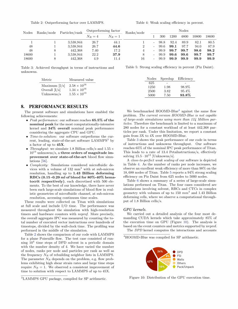
Table 2: Outperforming factor over LAMMPS.
Nodes Ranks/node Particles/rankOutperforming factor
NR = 4 NR = 1
1 1 3,538,944 26.7 44.148 1 3,538,944 26.7 44.648 8 442,368 7.40 17.2
18600 1 3,538,944 22.2 37.918600 8 442,368 4.9 11.4
Table 3: Achieved throughput in terms of instructions andunknowns.
Metric Measured value
Maximum [I/s] 2.58× 10¹⁶
Overall [I/s] 1.34× 10¹⁶
Unknowns/s 1.55× 10¹³
8. PERFORMANCE RESULTSThe present software and simulations have enabled the
following achievements:• Peak performance: our software reaches 65.5% of the
nominal peak for the most computationally-intensivekernel and 34% overall nominal peak performanceconsidering the aggregate CPU and GPU.• Time-to-solution: our software outperforms the cur-
rent, leading, state-of-the-art software LAMMPS3 bya factor of up to 45X.• Throughput: we simulate 1.8 Billion cells/s and 1.55×
1013 unknowns/s, a three orders of magnitude im-provement over state-of-the-art blood flow simu-lations [56].• Complexity: Simulations considered microfluidic de-
vices with a volume of 132 mm3 with at sub-micronresolution, handling up to 1.43 Billion deformingRBCs (0.15 -0.29 ml of blood for 80%-40% hema-tocrit respectively), each discretised with 500 ele-ments. To the best of our knowledge, there have neverbeen such large-scale simulations of blood flow in real-istic geometries of microfluidic channel, at sub-micronresolution, accessing continuum time scales.
These results were collected on Titan with simulationsat full scale and include I/O time. The performance wasmeasured throughout the simulation with high-resolutiontimers and hardware counters with nvprof. More precisely,the overall aggregate IPC was measured by counting the to-tal number of executed vector instructions over hundreds oftimesteps, divided by the wall-clock time. The profiling wasperformed in the middle of the simulation.
Table 2 shows the comparison of our code with LAMMPSfor a plane Poiseuille flow. The test case consisted of run-ning 104 time steps of DPD solvent in a periodic domainwith the number density of 4. We have varied the numberof nodes, ranks per node and particles per rank as well asthe frequency NR of rebuilding neighbor lists in LAMMPS.The parameter NR depends on the problem, e.g. flow prob-lems exhibiting high shear strain rates and large time stepsrequire NR = 1. We observed a consistent improvement oftime to solution with respect to LAMMPS of up to 45X.
3LAMMPS GPU package, compiled for SP arithmetic.
Table 4: Weak scaling efficiency in percent.
Ranks/nodeNodes
1 300 1200 4800 10800 18600
1 - 98.8 92.4 89.9 82.1 80.52 - 99.6 99.1 97.7 94.0 87.94 - 99.9 99.7 99.7 98.6 98.28 - 99.9 99.6 99.6 99.7 99.7
16 - 99.9 99.9 99.9 99.9 99.9
Table 5: Strong scaling efficiency in percent (Piz Daint).
Nodes Speedup Efficiency625 - -1250 1.98 98.9%2500 3.82 95.4%5000 7.50 93.8%
We benchmarked HOOMD-Blue4 against the same flowproblem. The current version HOOMD-Blue is not capableof large-scale simulations using more than 124 Million par-ticles. Therefore the benchmark is limited to a maximum of280 nodes for a constant workload of at least 442,368 par-ticles per rank. Under this limitation, we report a constantgain from 3X to 4X over HOOMD-Blue.
Table 3 shows the peak performance of our code in termsof instructions and unknowns throughput. Our softwarereaches 65% of the nominal IPC peak performance of Titan.This leads to a rate of 13.4 PetaInstructions/s, effectivelysolving 15.5 · 1012 [Unknowns/s].
A close-to-perfect weak scaling of our software is depictedin Table 4. As the number of ranks per node increases, weobserve an excellent weak efficiency of more than 98% on the18, 688 nodes of Titan. Table 5 reports a 94% strong scalingefficiency on Piz Daint from 625 nodes to 5000 nodes.
Table 6 shows a summary of a series of large-scale simu-lations performed on Titan. The four cases considered aresimulations involving solvent, RBCs and CTCs in complexgeometry with volumes of up to 150 mm3 and 1.43 Billiondeforming cells, where we observe a computational through-put of 1.8 Billion cells/s.
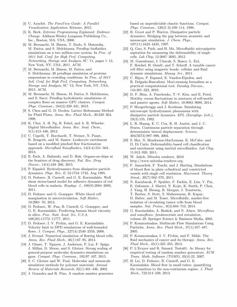
GPU kernels.We carried out a detailed analysis of the four most de-
manding CUDA kernels which take approximately 85% ofthe execution time on GPU (Figure 10). The analysis isbased on the event counters and metrics supported by nvprof.
The DPD kernel computes the interactions and accounts
4HOOMD-Blue was compiled for SP arithmetic.
Table 1
DPD 42
FSI 24.2
Walls 7.6
Others 10.9
Pack/Unpack 15.5
15%
11%
8%
24%
42%
DPDFSIWallsOthersPack/Unpack
Figure 10: Distribution of the GPU execution time.
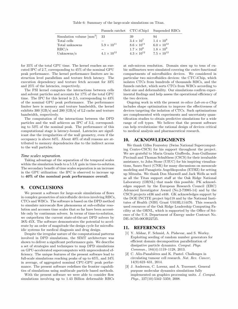
Table 6: Summary of the large-scale simulations on Titan.
Funnels ratchet CTC-iChip1 Suspended RBCs
Simulation volume [mm3] 33 39 94Total cells − 3.4× 10⁷ 1.4× 10⁹
Total unknowns 5.9× 10¹¹ 8.6× 10¹¹ 6.0× 10¹²
RBC/s − 1.7× 10⁸ 1.8× 10⁹
Unknowns/s 4.1× 10¹² 4.3× 10¹² 7.5× 10¹²
for 35% of the total GPU time. The kernel reaches an exe-cuted IPC of 2.7, corresponding to 45% of the nominal GPUpeak performance. The kernel performance limiters are in-struction level parallelism and texture fetch latency. Theexecution dependency and texture fetch account for 33%and 25% of the latencies, respectively.
The FSI kernel computes the interactions between cellsand solvent particles and accounts for 17% of the total GPUtime. The IPC for this kernel is 2.5, corresponding to 43%of the nominal GPU peak performance. The performancelimiter here is memory and texture bandwidth, the kernelexhibits 300 [GB/s] and 200 [GB/s] of L2 cache and texturebandwidth, respectively.
The computation of the interactions between the DPDparticles and the wall achieves an IPC of 3.2, correspond-ing to 53% of the nominal peak. The performance of thiscomputational stage is latency-bound. Latencies are signif-icant due the irregularities of the wall geometry, even if theoccupancy is above 84%. About 40% of stall reasons are at-tributed to memory dependencies due to the indirect accessto the wall particles.
Time scales separation.Taking advantage of the separation of the temporal scales
within the simulation leads to a 5.5X gain in time-to-solution.The secondary benefit of time scales separation is an increasein the GPU utilization: the IPC is observed to increase upto 40% of the nominal peak performance overall.
9. CONCLUSIONSWe present a software for large-scale simulations of flows
in complex geometries of microfluidic devices involving RBCs,CTCs and WBCs. The software is based on the DPD methodto simulate microscale flow phenomena at sub-cellular reso-lution and accesses time scales that so far have been accessi-ble only by continuum solvers. In terms of time-to-solution,we outperform the current state-of-the-art DPD solvers by38X-45X. The software demonstrates the potential to accel-erate by an order of magnitude the design cycle for microflu-idic systems for medical diagnosis and drug design.
Despite the irregular nature of the computational patternsinvolved in DPD simulations, the SIMT architecture wasshown to deliver a significant performance gain. We describea set of strategies and techniques to map DPD simulationson GPU-accelerated supercomputers with unprecedented ef-ficiency. The unique features of the present software lead tofull-scale simulations reaching peaks of up to 65%, and 34%in average, of aggregated nominal CPU-GPU peak perfor-mance. The present software redefines the frontier capabili-ties of simulations using multiscale particle based methods.
With the present software we were able to consider flowsimulations involving up to 1.43 Billion deformable RBCs
at sub-micron resolution. Domain sizes up to tens of cu-bic millimeters were simulated covering the entire functionalcompartments of microfluidics devices. We considered inparticular two microfluidics devices: the CTC-iChip, whichisolates CTCs from hundreds of thousands RBCs, and thefunnels ratchet, which sorts CTCs from WBCs according totheir size and deformability. Our simulations confirm exper-imental findings and help assess the operational efficiency ofthe two devices.
Ongoing work in with the present in-silico Lab-on-a-Chipincludes shape optimization to improve the effectiveness ofdevices targeting the isolation of CTCs. Such optimizationsare complemented with experiments and uncertainty quan-tification studies to obtain predictive simulations for a widerange of cell types. We believe that the present softwarecan help revolutionise the rational design of devices criticalto medical analysis and pharmaceutical research.
10. ACKNOWLEDGMENTSWe thank Gilles Fourestey (Swiss National Supercomput-
ing Centre-CSCS) for his support throughout the project.We are grateful to Maria Grazia Giuffreda, Jean-GuillaumePiccinali and Thomas Schulthess (CSCS) for their invaluableassistance, to John Stone (UIUC) for his inspiring visualiza-tions, Sauro Succi (CNR) for many discussions on mesoscalemodeling and Panagiotis Angelikopoulos (ETHZ) for settingup Mitsuba. We thank Don Maxwell and Jack Wells as wellas all the Titan support staff at the Oak Ridge NationalLaboratory (ORNL) that made this possible. PK acknowl-edges support by the European Research Council (ERC)Advanced Investigator Award (No.2-73985-14) and by theCSCS projects s436 and s448. GK acknowledges support bythe DOE INCITE project bip118 and by the National Insti-tutes of Health (NIH) Grant U01HL114476. This researchused resources of the Oak Ridge Leadership Computing Fa-cility at the ORNL, which is supported by the Office of Sci-ence of the U.S. Department of Energy under Contract No.DE-AC05-00OR22725.
11. REFERENCES[1] Y. Afshar, F. Schmid, A. Pishevar, and S. Worley.
Exploiting seeding of random number generators forefficient domain decomposition parallelization ofdissipative particle dynamics. Comput. Phys.Commun., 184(4):1119–1128, 2013.
[2] C. Alix-Panabieres and K. Pantel. Challenges incirculating tumour cell research. Nat. Rev. Cancer,14(9):623–631, 2014.
[3] J. Anderson, C. Lorenz, and A. Travesset. Generalpurpose molecular dynamics simulations fullyimplemented on graphics processing units. J. Comput.Phys., 227(10):5342–5359, 2008.
[4] U. Ayachit. The ParaView Guide: A ParallelVisualization Application. Kitware, 2015.
[5] K. Beck. Extreme Programming Explained: EmbraceChange. Addison-Wesley Longman Publishing Co.,Inc., Boston, MA, USA, 2000.
[6] M. Bernaschi, M. Bisson, T. Endo, S. Matsuoka,M. Fatica, and S. Melchionna. Petaflop biofluidicssimulations on a two million-core system. In Proc. of2011 Intl. Conf. for High Perf. Computing,Networking, Storage and Analysis, SC ’11, pages 1–12,New York, NY, USA, 2011. ACM.
[7] M. Bernaschi, M. Bisson, M. Fatica, andS. Melchionna. 20 petaflops simulation of proteinssuspensions in crowding conditions. In Proc. of 2013Intl. Conf. for High Perf. Computing, Networking,Storage and Analysis, SC ’13, New York, NY, USA,2013. ACM.
[8] M. Bernaschi, M. Bisson, M. Fatica, S. Melchionna,and S. Succi. Petaflop hydrokinetic simulations ofcomplex flows on massive GPU clusters. Comput.Phys. Commun., 184(2):329–341, 2013.
[9] S. Chen and G. D. Doolen. Lattice Boltzmann Methodfor Fluid Flows. Annu. Rev. Fluid Mech., 30:329–364,1998.
[10] K. Choi, A. H. Ng, R. Fobel, and A. R. Wheeler.Digital Microfluidics. Annu. Rev. Anal. Chem.,5(1):413–440, 2012.
[11] C. Cupelli, T. Borchardt, T. Steiner, N. Paust,R. Zengerle, and M. Santer. Leukocyte enrichmentbased on a modified pinched flow fractionationapproach. Microfluid Nanofluidics, 14(3-4):551–563,2013.
[12] E. Esch, A. Bahinski, and D. Huh. Organs-on-chips atthe frontiers of drug discovery. Nat. Rev. DrugDiscov., 14(4):248–260, 2015.
[13] P. Espanol. Hydrodynamics from dissipative particledynamics. Phys. Rev. E, 52:1734–1742, Aug 1995.
[14] D. Fedosov, B. Caswell, and G. E. Karniadakis. Wallshear stress-based model for adhesive dynamics of redblood cells in malaria. Biophys. J., 100(9):2084–2093,2011.
[15] D. Fedosov and G. Gompper. White blood cellmargination in microcirculation. Soft Matter,10:2961–70, 2014.
[16] D. Fedosov, W. Pan, B. Caswell, G. Gompper, andG. E. Karniadakis. Predicting human blood viscosityin silico. Proc. Natl. Acad. Sci. U.S.A,108(29):11772–11777, 2011.
[17] D. Fedosov, I. V. Pivkin, and G. E. Karniadakis.Velocity limit in DPD simulations of wall-boundedflows. J. Comput. Phys., 227(4):2540–2559, 2008.
[18] J. Freund. Numerical simulation of flowing blood cells.Annu. Rev. Fluid Mech., 46(1):67–95, 2014.
[19] J. Glaser, T. Nguyen, J. Anderson, P. Lui, F. Spiga,J. Millan, D. Morse, and S. Glotzer. Strong scaling ofgeneral-purpose molecular dynamics simulations ongpus. Comput. Phys. Commun., 192:97–107, 2015.
[20] S. C. Glotzer and W. Paul. Molecular and mesoscalesimulation methods for polymer materials. AnnualReview of Materials Research, 32(1):401–436, 2002.
[21] J. Gonzalez and R. Pino. A random number generator
based on unpredictable chaotic functions. Comput.Phys. Commun., 120(2–3):109–114, 1999.
[22] R. Groot and P. Warren. Dissipative particledynamics: Bridging the gap between atomistic andmesoscopic simulation. J. Chem. Phys.,107(11):4423–4435, 1997.
[23] Q. Guo, S. Park, and H. Ma. Microfluidic micropipetteaspiration for measuring the deformability of singlecells. Lab Chip, 12:2687–2695, 2012.
[24] M. Gusenbauer, I. Cimrak, S. Bance, L. Exl,F. Reichel, H. Oezelt, and T. Schrefl. A tunable cancercell filter using magnetic beads: cellular and fluiddynamic simulations. Manag. Sci., 2011.
[25] C. Hijon, P. Espanol, E. Vanden-Eijnden, andR. Delgado-Buscalioni. Mori-zwanzig formalism as apractical computational tool. Faraday Discuss.,144:301–322, 2010.
[26] D. F. Hinz, A. Panchenko, T.-Y. Kim, and E. Fried.Motility versus fluctuations in mixtures of self-motileand passive agents. Soft Matter, 10:9082–9089, 2014.
[27] P. Hoogerbrugge and J. Koelman. Simulatingmicroscopic hydrodynamic phenomena withdissipative particle dynamics. EPL (Europhys. Lett.),19(3):155, 1992.
[28] L. R. Huang, E. C. Cox, R. H. Austin, and J. C.Sturm. Continuous particle separation throughdeterministic lateral displacement. Science,304(5673):987–990, 2004.
[29] S. Hur, N. Henderson-MacLennan, E. McCabe, andD. Di Carlo. Deformability-based cell classificationand enrichment using inertial microfluidics. Lab Chip,11:912–920, 2011.
[30] W. Jakob. Mitsuba renderer, 2010.http://www.mitsuba-renderer.org.
[31] F. Janoschek, F. Toschi, and J. Harting. Simulationsof blood flow in plain cylindrical and constrictedvessels with single cell resolution. Macromol. TheorySimul., 20(7):562–570, 2011.
[32] N. Karabacak, P. Spuhler, F. Fachin, E. Lim, V. Pai,E. Ozkumur, J. Martel, N. Kojic, K. Smith, P. Chen,J. Yang, H. Hwang, B. Morgan, J. Trautwein,T. Barber, S. Stott, S. Maheswaran, R. Kapur,D. Haber, and M. Toner. Microfluidic, marker-freeisolation of circulating tumor cells from bloodsamples. Nat. Protoc., 9(3):694–710, 2014.
[33] G. Karniadakis, A. Beskok, and N. Aluru. Microflowsand nanoflows: fundamentals and simulation,volume 29. Springer Science & Business Media, 2005.
[34] P. Koumoutsakos. Multiscale Flow Simulations UsingParticles. Annu. Rev. Fluid Mech., 37(1):457–487,2005.
[35] P. Koumoutsakos, I. V. Pivkin, and F. Milde. Thefluid mechanics of cancer and its therapy. Annu. Rev.Fluid Mech., 45(1):325–355, 2013.
[36] P. L’Ecuyer and R. Simard. Testu01: Ac library forempirical testing of random number generators. ACMTrans. Math. Software (TOMS), 33(4):22, 2007.
[37] H. Lei, D. Fedosov, B. Caswell, and G. E.Karniadakis. Blood flow in small tubes: quantifyingthe transition to the non-continuum regime. J. FluidMech., 722:214–239, 2013.

[38] H. Lei and G. E. Karniadakis. Quantifying therheological and hemodynamic characteristics of sicklecell anemia. Biophys. J., 102(2):185–194, 2012.
[39] J. Li, M. Dao, C. Lim, and S. Suresh. Spectrin-levelmodeling of the cytoskeleton and optical tweezersstretching of the erythrocyte. Biophys. J.,88(5):3707–3719, 2005.
[40] H. Liu, Q. Tan, W. Geddie, M. Jewett, N. Phillips,D. Ke, C. Simmons, and Y. Sun. Biophysicalcharacterization of bladder cancer cells with differentmetastatic potential. Cell Biochem. Biophys.,68(2):241–246, 2014.
[41] G. Marsaglia and A. Zaman. The KISS generator.Technical report, Dept. of Statistics, University ofFlorida, 1993.
[42] S. McFaul, B. Lin, and H. Ma. Cell separation basedon size and deformability using microfluidic funnelratchets. Lab Chip, 12:2369–2376, 2012.
[43] D. T. Miyamoto, L. V. Sequist, and R. J. Lee.Circulating tumour cells:monitoring treatmentresponse in prostate cancer. Nature Reviews ClinicalOncology, 11(7):401–412, 07 2014.
[44] K. Muller, D. Fedosov, and G. Gompper. Marginationof micro- and nano-particles in blood flow and itseffect on drug delivery. Sci. Rep., 4, 2014.
[45] L. Nan, Z. Jiang, and X. Wei. Emerging microfluidicdevices for cell lysis: a review. Lab on a Chip,14:1060–1073, 2014.
[46] B. J. Nelson, I. K. Kaliakatsos, and J. J. Abbott.Microrobots for minimally invasive medicine. Annu.Rev. Biomed. Eng., 12:55–85, 2010.
[47] T. Nguyen and S. Plimpton. Accelerating dissipativeparticle dynamics simulations for soft matter systems.Comput. Mater. Sci., 100:173–180, 2015.
[48] W. Pan, I. V. Pivkin, and G. E. Karniadakis.Single-particle hydrodynamics in dpd: A newformulation. EPL (Europhys. Lett.), 84(1):10012, 2008.
[49] K. Pantel and M. R. Speicher. The biology ofcirculating tumor cells. Oncogene, pages –, 06 2015.
[50] Z. Peng, X. Li, I. V. Pivkin, M. Dao, G. E.Karniadakis, and S. Suresh. Lipid bilayer andcytoskeletal interactions in a red blood cell. Proc.Natl. Acad. Sci. U.S.A, 110:13356–13361, 2013.
[51] C. Phillips, J. Anderson, and S. Glotzer.Pseudo-random number generation for BrownianDynamics and Dissipative Particle Dynamicssimulations on GPU devices. J. Comput. Phys.,230(19):7191–7201, 2011.
[52] D. Pinho, T. Yaginuma, and R. Lima. A microfluidicdevice for partial cell separation and deformabilityassessment. Biochip J., 7:367–374, 2013.
[53] I. V. Pivkin and G. E. Karniadakis. Accuratecoarse-grained modeling of red blood cells. Phys. Rev.Lett., 101(11):1–4, 2008.
[54] S. Plimpton. Fast parallel algorithms for short-rangemolecular dynamics. J. Comput. Phys., 117(1):1–19,1995.
[55] D. Quinn, I. V. Pivkin, S. Wong, K. Chiam, M. Dao,G. E. Karniadakis, and S. Suresh. Combinedsimulation and experimental study of largedeformation of red blood cells in microfluidic systems.
Ann. Biomed. Eng., 39(2):1041–1050, 2011.
[56] A. Rahimian, I. Lashuk, S. Veerapaneni,A. Chandramowlishwaran, D. Malhotra, L. Moon,R. Sampath, A. Shringarpure, J. Vetter, R. Vuduc,D. Zorin, and G. Biros. Petascale direct numericalsimulation of blood flow on 200k cores andheterogeneous architectures. In Proc. of the 2010ACM/IEEE Intl. Conf. for High Perf. Computing,Networking, Storage and Analysis, SC ’10, pages 1–11,Washington, DC, USA, 2010. IEEE Computer Society.
[57] J. W. Scannell, A. Blanckley, H. Boldon, andB. Warrington. Diagnosing the decline inpharmaceutical r&d efficiency. Nat Rev Drug Discov,11(3):191–200, 03 2012.
[58] T. Schlick. Time-trimming tricks for dynamicsimulations: splitting force updates to reducecomputational work. Structure, 9(4), 2001.
[59] T. M. Squires and S. R. Quake. Microfluidics: Fluidphysics at the nanoliter scale. Rev. Mod. Phys.,77:977–1026, 2005.
[60] T. Steiner, C. Cupelli, R. Zengerle, and M. Santer.Simulation of advanced microfluidic systems withdissipative particle dynamics. Microfluid Nanofluidics,7(3):307–323, 2009.
[61] A. Streets and Y. Huang. Chip in a lab: Microfluidicsfor next generation life science research.Biomicrofluidics, 7(1), 2013.
[62] Y. Tang and G. E. Karniadakis. Acceleratingdissipative particle dynamics simulations on gpus:Algorithms, numerics and applications. Comput. Phys.Commun., 185(11):2809–2822, 2014.
[63] D. Visser, H. Hoefsloot, and P. Iedema.Comprehensive boundary method for solid walls indissipative particle dynamics. J. Comput. Phys.,205(2):626–639, 2005.
[64] N. Wagner. The logistic lattice in random numbergeneration. In Proc. of the Annual Conf. onCommunication Control and Computing, volume 30,pages 922–922. University of Illinois, 1992.
[65] Q. Wei, Y. Xu, F. Tian, T. Gao, X. Tang, and W. Zu.Ib-lbm simulation on blood cell sorting with amicro-fence structure. Bio-Med. Mater. Eng.,24:475–481, 2014.
[66] D. J. Wheeler and R. M. Needham. Tea, a tinyencryption algorithm. In Fast Software Encryption,pages 363–366. Springer, 1995.
[67] G. Whitesides. The origins and the future ofmicrofluidics. Nature, 442(7101):368–372, 2006.
[68] D. Xu, E. Kaliviotis, A. Munjiza, E. Avital, C. Ji, andJ. Williams. Large scale simulation of red blood cellaggregation in shear flows. J. Biomech.,46(11):1810–1817, 2013.
[69] C. Yung, J. Fiering, A. Mueller, and D. Ingber.Micromagnetic-microfluidic blood cleansing device.Lab on a Chip, 9:1171–1177, 2009.
[70] P. Zhang, N. Zhang, Y. Deng, and D. Bluestein. Amultiple time stepping algorithm for efficientmultiscale modeling of platelets flowing in bloodplasma. J. Comput. Phys., 284:668–686, 2015.


![[Velocity Ignite] Petascale Storage](https://img.pdfslide.us/doc/110x75/55492f5fb4c90547498c299c/velocity-ignite-petascale-storage.jpg)