Embed Size (px)
Citation preview

The Implementation of the AMRES VPNService
Best Practice Document
Produced by the AMRES-led working groupon Security(AMRES BPD 112)
Authors: Jovana Palibrk, Ivan Ivanović,Dušan Pajin March, 2013

2
© TERENA 2010. All rights reserved. Document No: GN3-NA3-T4-AMRES-BPD-112 Version / date: March 2013 Original language : Serbian Original title: “Implementacija AMRES VPN servisa” Original version / date: Revision 1 (of the document dated 12 February 2012) 18 March 2013 Contact: [email protected], [email protected] AMRES/RCUB is responsible for the contents of this document. The document was developed by the AMRES-led working group on Security with the purpose of implementing joint activities on the development and dissemination of documents encompassing technical guidelines and recommendations for network services in higher education and research institutions in Serbia. Parts of the report may be freely copied, unaltered, provided that the original source is acknowledged and copyright preserved. The research leading to these results has received funding from the European Community's Seventh Framework Programme (FP7/2007-2013) under grant agreement n° 238875, relating to the project 'Multi-Gigabit European Research and Education Network and Associated Services (GN3)'.

3
Table of Contents
Summary 4
Introduction 5
1 The Planning 6 1.1 The Requirements 6 1.2 The Architecture and the Selection of Solution Technology 7
2 The Implementation 12 2.1 The VPN Server 12
2.1.1 OpenVPN 12 2.1.2 Configuring the VPN Concentrator 13 2.1.3 Configuring the VPN Client 23
2.2 The RADIUS Infrastructure 23 2.2.1 Configuring the Top Level RADIUS Server 24 2.2.2 An Example of an Institution’s RADIUS Server Configuration 32
3 Conclusion 35
References 36
Glossary 37

4
Summary
VPN (Virtual Private Network) technology enables a safe connection between a user at a remote location and his/her home institution through a shared or public network infrastructure (e.g., Internet). The basic requirements to be met by such a solution are:
data confidentiality – protection from unauthorised access to information;
data integrity – protection from unauthorised data modification;
authentication – confirmation of the identity of devices at the ends of the VPN tunnel.
This document describes the deployment of the AMRES VPN service. This solution involves the implementation of the SSL/TSL protocol using OpenVPN technology. The main advantages of an OpenVPN solution are the implementation of advanced data encryption algorithms, the simplicity of installation and maintenance, and the fact that it is supported by almost all of the client and server platforms that are popular today. For user authentication, the AMRES VPN service relies on the RADIUS infrastructure, which was developed for AMRES’ eduroam® service. The document also provides a detailed configuration of the relevant RADIUS servers on the FreeRADIUS platform.
5
Introduction
This document presents the technical solution and the implementation of the infrastructure that provides the VPN service to individual AMRES users. AMRES’ VPN service provides AMRES users who are located in an external network with access to the resources and services that are normally available only from the AMRES network. The AMRES VPN service is intended for AMRES users who access the Internet in various ways - using ADSL technology and cable access, or while travelling (for example, at other universities, hotels, or airports).
The first part of the document describes the services and the requirements that the services dictate to the VPN infrastructure. The second part provides a detailed configuration of the basic components comprising the AMRES VPN service, the VPN and the RADIUS server.

6
1 The Planning
1.1 The Requirements
The first step in process of planning the implementation of the VPN service is to recognise services and resources that could be of interest to the AMRES VPN users and the requirements that should be met by the implemented technology. VPN technology has been implemented in the AMRES network with the aim of providing recognised services and resources to its remote users under conditions identical to those the users have when accessing these services through the local computer network. In order to define the requirements to be met by the VPN solution, a set of AMRES services has been selected that the users can access through the VPN infrastructure. The VPN infrastructure in the AMRES network has been implemented in such a way that it does not explicitly exclude the possibility of using additional AMRES services, though their implementation is largely dependent on the logical architecture of the computer network of the relevant AMRES member organisation. This technical solution permits AMRES member institutions to adjust the infrastructure in order to enable access for their remote internal users to AMRES services.
Remote AMRES users can use following services through the AMRES VPN service.
KOBSON Proxy service eLearning server E-mail Remote desktop at the user's computer Access to specialised information systems and services (e.g., university IS, and faculty services) Other services that are only accessible from inside the AMRES network
A particularly interesting service is KOBSON, which enables the internal user to access databases containing scientific magazines and publications in an electronic form. The KOBSON service is available only from the academic network and through one of the registered proxy servers within the KOBSON system. AMRES VPN service provides AMRES users with access to the KOBSON service from locations outside the academic network, through the same, registered proxy servers.
The general requirements that the AMRES VPN solution needs to meet are:
user authentication based on the user credentials; authorisation, which implements the assignment of an IP address to the user; accounting mechanisms that monitor user activity.
7
Broadband access technologies are primarily used nowadays (e.g., ADSL, cable access, and wireless access). Access based on these technologies is established through commercial Internet service providers. Thus, a potential remote user should access the AMRES services via the Internet, which is a communication infrastructure that does not guarantee security. Therefore, from a security point of view, the implemented VPN technology includes:
mechanisms that protect the confidentiality and integrity of the information necessary to authenticate users;
mechanisms for the protection of the confidentiality and integrity of the data exchanged between the individual users and the available services.
The technology that enables access to individual AMRES users from external networks must not be dependent on the technology used to establish the users’ access to the Internet.
1.2 The Architecture and the Selection of Solution Technology
The basic components of the VPN service are the VPN client and the VPN concentrator (server). It is necessary that they implement the same VPN technology. There are several technologies enabling the implementation of the VPN client and the VPN concentrator functions. The selected technology has to meet the minimum requirements relating to authentication, authorisation, accounting, and security. In addition, it is also important that the selected technology be supported by the operating system of both the VPN concentrator and the VPN client. The selected solution should be compatible with every currently popular operating system (Windows, Linux, Mac OS, Solaris, FreeBSD, NetBSD, and OpenBSD).
Taking into account all of the above requirements, the OpenVPN software package, which among other features, uses the SSL/TLS protocol, has been selected for the implementation of the AMRES VPN service. The basic principles of its functionality and the advantages of the Open VPN program are presented in the next chapter.
The functions of authentication, authorisation, and accounting have been implemented using the existing hierarchical RADIUS infrastructure that is used in the eduroam® service. Accordingly, the RADIUS infrastructure comprises two levels:
the first level encompasses the VPN TLR (Top Level RADIUS) server that has the role of the proxy RADIUS server. This server contains a list of the domains of the AMRES institutions using the VPN service;
the second level comprises the RADIUS servers of the end institutions, which are responsible for the authentication of their users. The home institutions are responsible for maintaining the data and credentials of their users. This data is usually kept in the user database that the RADIUS server uses in the process of authentication. Since the eduroam® service relies on the same infrastructure, this allows users to use the same authentication parameters (the same username and password combination) for both services, i.e., AMRES VPN and eduroam®.
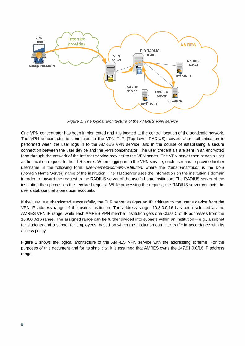
Figure 1 depicts the logical architecture of the AMRES VPN service
8
Figure 1: The logical architecture of the AMRES VPN service
One VPN concentrator has been implemented and it is located at the central location of the academic network. The VPN concentrator is connected to the VPN TLR (Top-Level RADIUS) server. User authentication is performed when the user logs in to the AMRES VPN service, and in the course of establishing a secure connection between the user device and the VPN concentrator. The user credentials are sent in an encrypted form through the network of the Internet service provider to the VPN server. The VPN server then sends a user authentication request to the TLR server. When logging in to the VPN service, each user has to provide his/her username in the following form: user-name@domain-institution, where the domain-institution is the DNS (Domain Name Server) name of the institution. The TLR server uses the information on the institution’s domain in order to forward the request to the RADIUS server of the user’s home institution. The RADIUS server of the institution then processes the received request. While processing the request, the RADIUS server contacts the user database that stores user accounts.
If the user is authenticated successfully, the TLR server assigns an IP address to the user’s device from the VPN IP address range of the user’s institution. The address range, 10.8.0.0/16 has been selected as the AMRES VPN IP range, while each AMRES VPN member institution gets one Class C of IP addresses from the 10.8.0.0/16 range. The assigned range can be further divided into subnets within an institution – e.g., a subnet for students and a subnet for employees, based on which the institution can filter traffic in accordance with its access policy.
Figure 2 shows the logical architecture of the AMRES VPN service with the addressing scheme. For the purposes of this document and for its simplicity, it is assumed that AMRES owns the 147.91.0.0/16 IP address range.

9
Figure 2: The distribution of IP addresses within the AMRES VPN service
Accounting is also implemented using the RADIUS server. The VPN server is configured to send the information about a user session to the TLR server. The TLR server stores this information in the appropriate SQL database.
The VPN server is based at the central location of the AMRES network. On the firewall system, UDP port 1194 is opened for the IP address of the server, since the OpenVPN service is configured to accept connections of the VPN clients though this port. The cryptographic protection of the traffic is ensured only between the client’s device and the VPN server. When the VPN server receives the traffic from the user, the traffic is decrypted and forwarded in its original form to its destination through the academic network. If the client traffic has been sent in plain text format before it has been encrypted, it will be forwarded by the VPN server to its destination in the AMRES network, also in plain text format.
Figures 3 and 4 illustrate the solution for routing within the VPN service. When a user connects to the AMRES network via the VPN service, a point-to-point virtual tunnel interface is established between the VPN server and the user device. A virtual IP address is assigned to each end of the tunnel. The virtual IP address of the server is 10.8.0.1, while the client gets an address from the range belonging to his/her home institution (one Class C from the 10.8.0.0/16 range), as shown in Figure 2. Figure 3 shows the route of the traffic from the VPN client to a host in the AMRES network. The AMRES VPN server has two network interfaces to which public IP addresses have been assigned. The purpose of one network interface is to connect the VPN clients to the VPN server and to establish the VPN tunnel – this is the external interface marked as eth0 on Figure 3. The IP address of this interface is 147.91.a.b. This network interface receives the traffic sent by the VPN clients. Following the decryption and encapsulation, the VPN device routes the traffic towards the AMRES network using the other, internal interface, which is marked as eth1 on Figure 3. The IP address of this interface is 147.91.c.d.

10
Figure 3: The routing of packets from the VPN client to the AMRES network
Figure 4 shows the situation in which the packets from the AMRES network are returned to the VPN client. The IP address of the VPN client is used as a source address of the IP packet the client sends through the VPN tunnel. The same address is also used as a source address in the packet when it leaves the SSL tunnel and reaches its destination. For this reason, the devices in the AMRES network must have a configured route to the 10.8.0.0/16 VPN IP address range, to which the clients’ addresses belong. This route directs the packets for the VPN range to the address of the internal interface of the VPN server – eth1.
Figure 4: The routing of packets by the AMRES network towards the VPN client
The AMRES VPN service supports split tunnelling. Split tunnelling is a process that allows a remote VPN user to simultaneously access a public network, most often the Internet, through his/her local network connection and the resources of his/her organisation using the established VPN tunnel. The AMRES VPN service is implemented in such a way that the traffic from the VPN user device towards all AMRES address ranges is sent through the VPN tunnel, while all other traffic from the user device is sent through the local network connection, as illustrated in Figure 3. This ensures greater efficiency and maintains the bandwidth, since the quantity of traffic sent through the VPN tunnel is reduced significantly.

11
Open source software packages have been selected for the implementation of this solution. The OpenVPN package has been used for configuring the VPN server, while the TLR server has been implemented using the FreeRADIUS program package. The details regarding the configuration of the VPN and TLR servers, as well as an example of the configuration required for the implementation of the RADIUS server institution are presented in the next chapter.
12
2 The Implementation
2.1 The VPN Server
2.1.1 OpenVPN
OpenVPN is an open source software package for the implementation of virtual private networks. A safe and stable SSL/TLS mechanism is used within the OpenVPN software for the establishment of secure communication between VPN points. Unlike the other SSL VPN solutions, which allow the use of an Internet browser on the client side, it is necessary to install the OpenVPN package on both the VPN server and the VPN client side.
The OpenVPN program runs in the Linux user space, rather than in the kernel space, which leads to increased security, and simpler installation and maintenance of the OpenVPN software on different platforms.
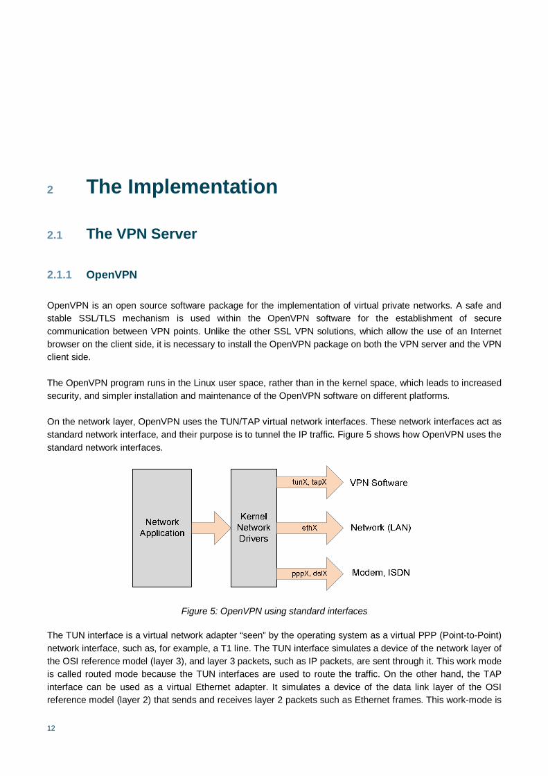
On the network layer, OpenVPN uses the TUN/TAP virtual network interfaces. These network interfaces act as standard network interface, and their purpose is to tunnel the IP traffic. Figure 5 shows how OpenVPN uses the standard network interfaces.
Figure 5: OpenVPN using standard interfaces
The TUN interface is a virtual network adapter “seen” by the operating system as a virtual PPP (Point-to-Point) network interface, such as, for example, a T1 line. The TUN interface simulates a device of the network layer of the OSI reference model (layer 3), and layer 3 packets, such as IP packets, are sent through it. This work mode is called routed mode because the TUN interfaces are used to route the traffic. On the other hand, the TAP interface can be used as a virtual Ethernet adapter. It simulates a device of the data link layer of the OSI reference model (layer 2) that sends and receives layer 2 packets such as Ethernet frames. This work-mode is

13
called bridging mode, since the TAP interface is used as a network bridge device. When data is sent via these interfaces, the data is sent to the TUN/TAP interface instead of the physical network adapter, from where it is taken over by the program in the user space that is connected to the interface, in this case, by the OpenVPN program. The VPN process encrypts the packets from the TUN or TAP virtual adapters using the SSL/TLS cryptography libraries. The data, thus encrypted, is subsequently encapsulated and sent to the other end of the tunnel. The UDP (standard) or TCP (optional) protocols can be used for packet encapsulation. When choosing the transport protocol into which the encrypted data from the TUN/TAP interface will be encapsulated, one needs to bear in mind that it is the packets already containing a transport protocol header (TCP and UDP) that are being encapsulated. The TCP protocol is designed to operate in an unreliable network environment. During the encapsulation from TCP into TCP, one reliable protocol is encapsulated into another reliable protocol, which may lead to decreased efficiency of services. Therefore, it is better to opt for encapsulation into UDP packets. Also, in this way, the IP packet is encapsulated into a protocol whose level of unreliability is more similar to that of the data link layer for which the IP protocol has been designed. Once the device on the other end of the SSL tunnel has received the encrypted and encapsulated packets, the OpenVPN process will first run de-encapsulation and de-encryption, and then it will send the packets to the TUN/TAP interface. Routing and safety rules can be applied to these interfaces just like to any hardware network adapters. In the course of configuring OpenVPN, it is possible to select all these parameters, as needed (the use of TUN or TAP interface, the encapsulation into UDP or TCP, and the port through which the connection will be established), but it is necessary to have the same parameters configured on both ends of the tunnel.
With these characteristics, the OpenVPN package offers the following possibilities:
simple installation on any operating system. It is possible to use the OpenVPN package on almost all operating systems that are popular today (Windows, Linux, Mac OS, Solaris, FreeBSD, NetBSD and OpenBSD);
a high level of flexibility – program scripts can be modified to suit specific needs (failover, load balancing);
transparency – it is not necessary to configure only static IP addresses on both sides of the tunnel, as IP addresses can also be dynamically assigned and users need not be aware of the change of IP address when the VPN tunnel is being established;
protection of remote users by way of the internal protective system (firewall) – a remote user connected to the central location through the VPN tunnel can change the network settings on his/her device so as to send all traffic through the tunnel. The central firewall service in the network to which the user is connected through the VPN tunnel can protect the user device, even though the device is not physically within the network that is protected by the firewall;
only one port needs to be open on the firewall system in order to allow incoming connections from the VPN clients;
virtual interfaces allow for specific network and firewall settings and rules – all the rules, restrictions, forwarding mechanisms and methods such as NAT (Network Address Translation) can be applied on the OpenVPN tunnels.
OpenVPN enables user authentication by way of a secret key, a certificate, or by username and password verification.
2.1.2 Configuring the VPN Concentrator
The OpenVPN server is set up by modifying the configuration files on the server and the client side. Before modifying these files, it is necessary to set the elements of the Public Key Infrastructure (PKI). These steps are explained, in detail, below. The location of the configuration file on the server side will depend on the manner in
14
which the OpenVPN package has been installed. In the case of the AMRES VPN server, a standard OpenVPN package that is included in the distribution of the operating system has been installed. Because of this, the configuration directory is /etc/openvpn, while the name of the configuration file, which is discussed below, is server.conf.
2.1.2.1 Creating Private and Public Keys
The first step in setting up the OpenVPN server is the configuration of the necessary parameters to be used for authentication, encryption, and keys exchange. VPN authentication should be mutual, i.e., the clients should authenticate the server and the server should also perform the client authentication, so that mutual trust and secure connections can be established. As noted in chapter 1.2, authentication of the VPN clients is performed through the RADIUS infrastructure. On the other hand, the elements of the PKI infrastructure are used in order for the VPN client to authenticate the VPN server. The PKI infrastructure comprises a private key, a certificate (with a public key) on the side of the server and the CA (Certificate Authority) certificate, and a key used for signing the server certificate. In authenticating the server, the client first verifies that the server certificate has been signed by the CA, and then checks the credibility of information, such as the value of the CN (Common Name) field in the server certificate containing the DNS name of the server.
In order to set up the PKI elements, the scripts obtained as part of the OpenVPN program are used. These scripts are located in the easy-rsa directory. The location of the easy-rsa directory can be found by using the following command:
$ find / -name easy-rsa
The assumption made in this document is that the scripts are located in the /usr/share/doc/openvpn directory.
By using the scripts from the easy-rsa directory, the CA private key and the certificate are created first (steps 1, 2, and 3). The private key and the certificate are then created for the VPN server and the server certificate is signed by the CA private key (step 4). Therefore, the VPN server certificate is self signed. The VPN client should have the CA certificate in order to authenticate the VPN server. Of course, it is possible to use a certificate for the VPN server, signed by another CA authority. For example, TERENA certificates, which are signed by the TERENA Certification Authority and available through the TCS Service (TERENA Certificate Service) can be used for this purpose. In this case, steps 1, 2, 3, and 4 would be skipped, and the TERENA CA and the obtained server certificate would be placed at the appropriate locations.
The steps that should be taken when configuring the PKI infrastructure elements are presented below.
1. The easy-rsa directory is copied onto the /etc/openvpn location
$ mkdir -m 700 -p /etc/openvpn/easy-rsa $ cd /etc/openvpn/easy-rsa $ cp -drp /usr/share/doc/openvpn/easy-rsa/2.0/*
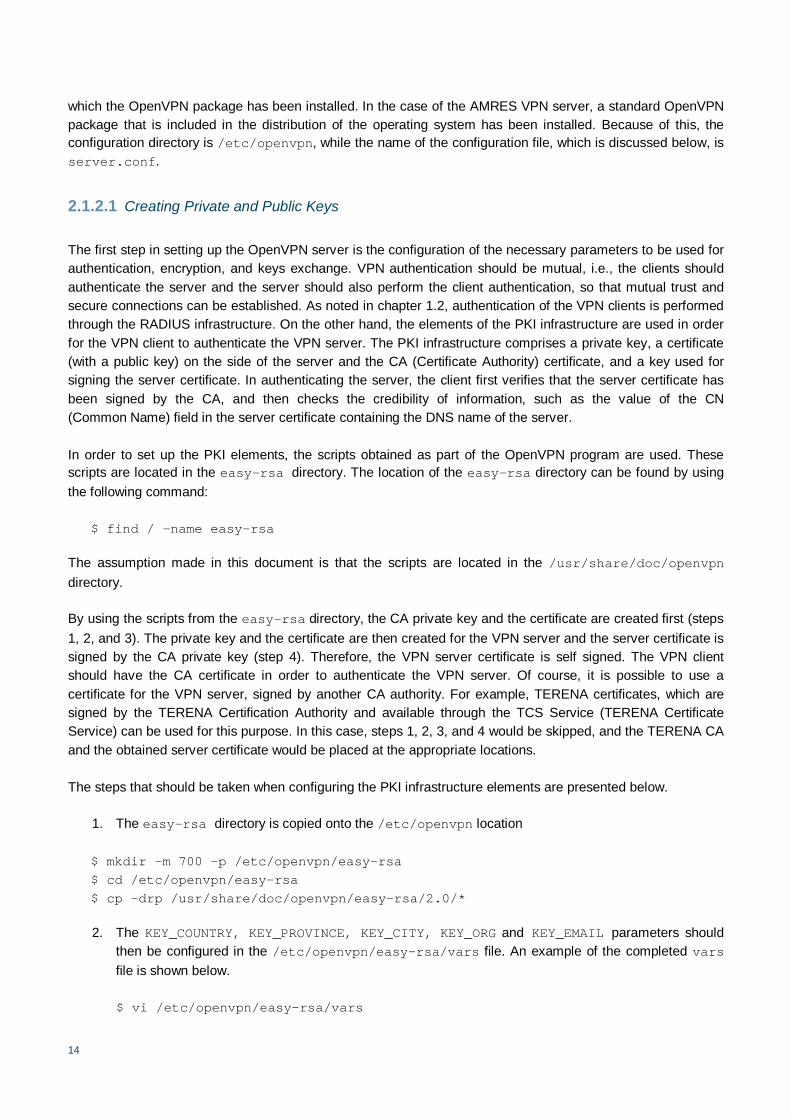
2. The KEY_COUNTRY, KEY_PROVINCE, KEY_CITY, KEY_ORG and KEY_EMAIL parameters should then be configured in the /etc/openvpn/easy-rsa/vars file. An example of the completed vars file is shown below.
$ vi /etc/openvpn/easy-rsa/vars
15
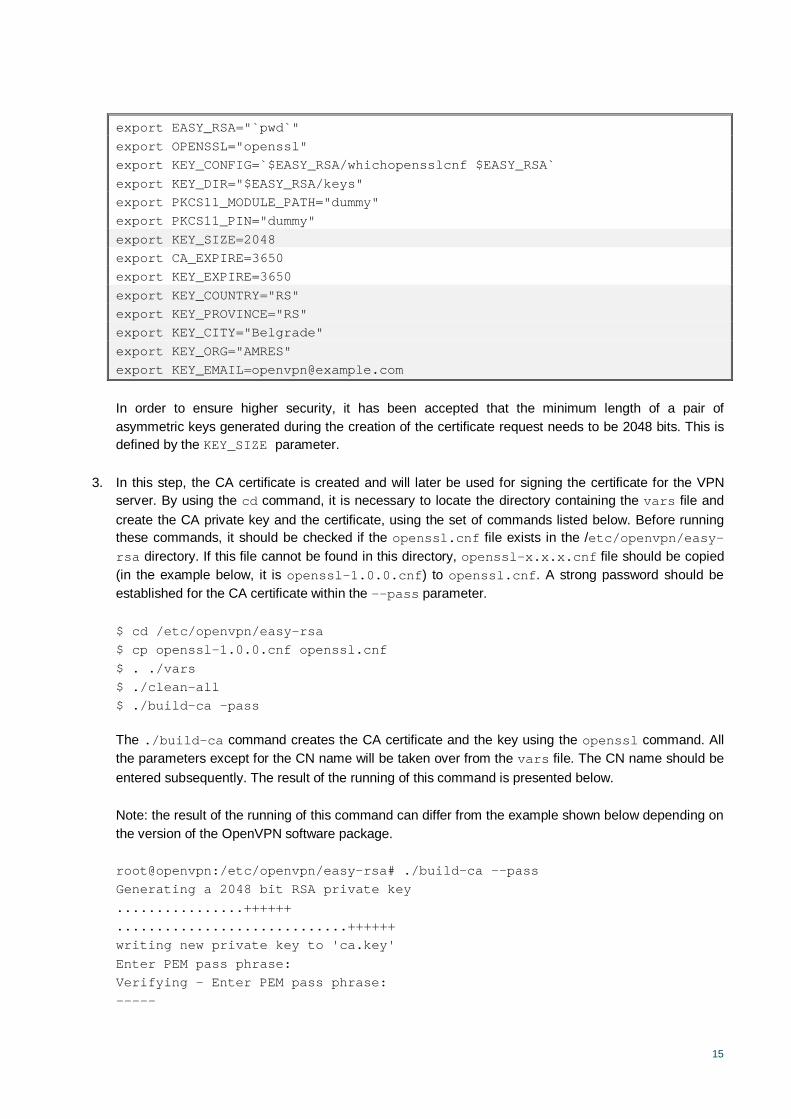
export EASY_RSA="`pwd`" export OPENSSL="openssl" export KEY_CONFIG=`$EASY_RSA/whichopensslcnf $EASY_RSA` export KEY_DIR="$EASY_RSA/keys" export PKCS11_MODULE_PATH="dummy" export PKCS11_PIN="dummy" export KEY_SIZE=2048 export CA_EXPIRE=3650 export KEY_EXPIRE=3650 export KEY_COUNTRY="RS" export KEY_PROVINCE="RS" export KEY_CITY="Belgrade" export KEY_ORG="AMRES" export [email protected]
In order to ensure higher security, it has been accepted that the minimum length of a pair of asymmetric keys generated during the creation of the certificate request needs to be 2048 bits. This is defined by the KEY_SIZE parameter.
3. In this step, the CA certificate is created and will later be used for signing the certificate for the VPN server. By using the cd command, it is necessary to locate the directory containing the vars file and create the CA private key and the certificate, using the set of commands listed below. Before running these commands, it should be checked if the openssl.cnf file exists in the /etc/openvpn/easy-rsa directory. If this file cannot be found in this directory, openssl-x.x.x.cnf file should be copied (in the example below, it is openssl-1.0.0.cnf) to openssl.cnf. A strong password should be established for the CA certificate within the --pass parameter.
$ cd /etc/openvpn/easy-rsa $ cp openssl-1.0.0.cnf openssl.cnf $ . ./vars $ ./clean-all $ ./build-ca –pass
The ./build-ca command creates the CA certificate and the key using the openssl command. All the parameters except for the CN name will be taken over from the vars file. The CN name should be entered subsequently. The result of the running of this command is presented below.
Note: the result of the running of this command can differ from the example shown below depending on the version of the OpenVPN software package.
root@openvpn:/etc/openvpn/easy-rsa# ./build-ca --pass Generating a 2048 bit RSA private key ................++++++ .............................++++++ writing new private key to 'ca.key' Enter PEM pass phrase: Verifying - Enter PEM pass phrase: -----

16
You are about to be asked to enter information that will be incorporated into your certificate request. What you are about to enter is what is called a Distinguished Name or a DN. There are quite a few fields but you can leave some blank For some fields there will be a default value, If you enter '.', the field will be left blank. ----- Country Name (2 letter code) [RS]: State or Province Name (full name) [RS]: Locality Name (eg, city) [Beograd]: Organization Name (eg, company) [AMRES]: Organizational Unit Name (eg, section) []: Common Name (eg, your name or your server's hostname) [AMRES CA]: Name [changeme]: openvpn Email Address [[email protected]]:
4. The next step is the generation of the server certificate and the private key. The server certificate will have been signed by the CA private key generated in the previous step. The build-key-server script is used for this purpose. When running this script, the name of the server (hostname) that will be entered in the CN field of the generated certificate should be specified. The result of the running of this script is shown below. When the ca.key password is requested within this script, the password for the CA certificate used in the previous step should be entered.
Note: the result of the running of this command can differ from the example shown below, depending on the version of the OpenVPN software package.
root@openvpn:/etc/openvpn/easy-rsa# ./build-key-server openvpn Generating a 2048 bit RSA private key ......++++++ ......++++++ writing new private key to 'openvpn.key' ----- You are about to be asked to enter information that will be incorporated into your certificate request. What you are about to enter is what is called a Distinguished Name or a DN. There are quite a few fields but you can leave some blank For some fields there will be a default value, If you enter '.', the field will be left blank. ----- Country Name (2 letter code) [RS]: State or Province Name (full name) [RS]: Locality Name (eg, city) [Beograd]: Organization Name (eg, company) [AMRES]: Organizational Unit Name (eg, section) []: Common Name (eg, your name or your server's hostname) [openvpn]: Name []: Email Address [[email protected]]: Please enter the following 'extra' attributes

17
to be sent with your certificate request A challenge password []: An optional company name []: Using configuration from /etc/openvpn/easy-rsa/2.0/openssl.cnf Enter pass phrase for /etc/openvpn/easy-rsa/2.0/keys/ca.key: Check that the request matches the signature Signature ok The Subject's Distinguished Name is as follows countryName :PRINTABLE:'RS' stateOrProvinceName :PRINTABLE:'RS' localityName :PRINTABLE:'Beograd' organizationName :PRINTABLE:'AMRES' commonName :PRINTABLE:'openvpn' emailAddress :IA5STRING:'[email protected]' Certificate is to be certified until Feb 13 17:03:04 2023 GMT (3650 days) Sign the certificate? [y/n]:y
1 out of 1 certificate requests certified, commit? [y/n]y Write out database with 1 new entries Data Base Updated
5. In order to introduce additional protection, another shared secret key should be generated – the tls-auth key, as follows.
$ cd /etc/openvpn/easy-rsa/keys $ openvpn --genkey --secret ta.key
The command generates the secret shared key and enters it in the ta.key file. This key should be transferred in a secure manner to the VPN server and the VPN client.
Additional protection obtained in this way implies the addition of the HMAC (Hash-based Message Authentication Code) signature to all packets exchanged in the course of the SSL/TLS handshake process, in order to verify the integrity of those packets. Any UDP packet that does not have the correct HMAC signature will be rejected without further processing. In this way, the server is also protected from:
DoS attacks;
scanning of the ports in order to establish which UDP port of the server is in the listening state;
initiation of SSL/TLS handshake by an authorised device (such an attempt would normally fail at the authentication stage, but with the tls-auth option, these attempts are prevented much earlier).
6. A key that will be used for the encryption of data within the VPN tunnel also needs to be created. The OpenVPN uses the DH (Diffie-Hellman) algorithm for the exchange and generation of keys. The DH protocol ensures safe exchange of the secret key between the VPN client and the VPN server. The build-dh script in the easy-rsa directory is used for generating the DH parameters. The script actually uses the openssl dhparam command, while the input parameters are defined in the vars file. The build-dh script is run by the following command:
18
root@openvpn:/etc/openvpn/easy-rsa# ./build-dh Generating DH parameters, 2048 bit long safe prime, generator 2 This is going to take a long time
This completes the generation of all the required keys. The next step is the setting up of the configuration files.
2.1.2.2 Setting up the Configuration Files
The OpenVPN program can be configured through the command line or through the configuration files. Although these two methods of configuration are identical, this document shows the configuration through the configuration files, since this method has proved to be simpler in comparison to using long commands. One of important advantages of this method lies in the fact that the format of the configuration files is the same in all operating systems, so, if required, it can easily be copied from one operating system to another.
A configuration file should be created on the server side. Examples of the configuration files can be found in the sample-config-files directory. This directory can be located by using the following command.
$ find / -name sample-config-files
In this case, it is assumed that the directory with examples of configuration files is located in the /usr/share/doc/openvpn-2.0 directory.
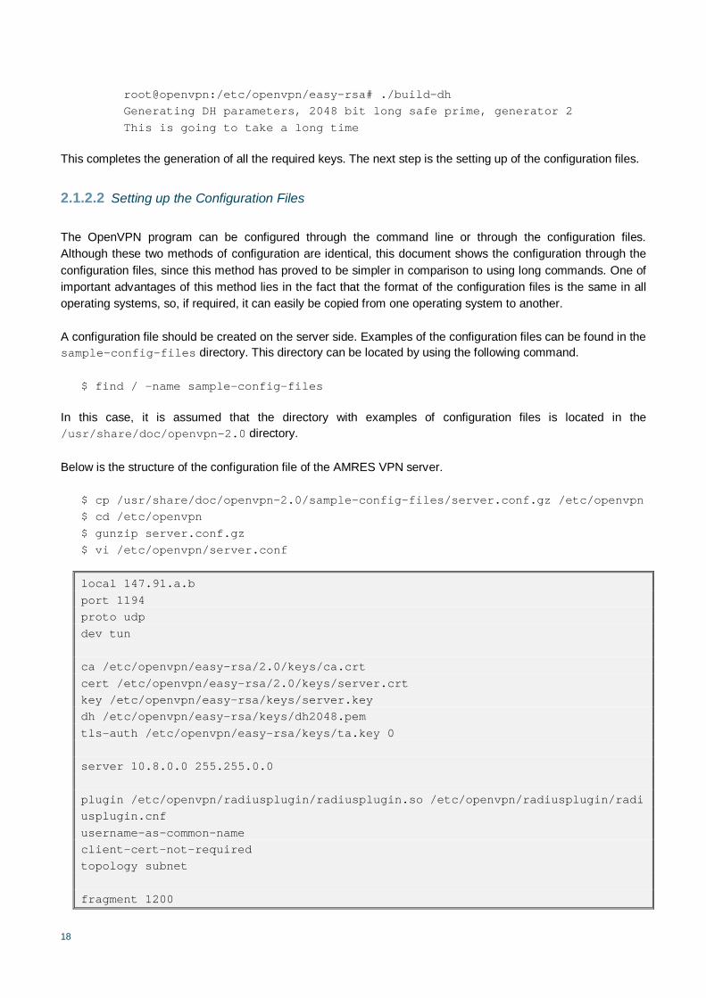
Below is the structure of the configuration file of the AMRES VPN server.
$ cp /usr/share/doc/openvpn-2.0/sample-config-files/server.conf.gz /etc/openvpn $ cd /etc/openvpn $ gunzip server.conf.gz $ vi /etc/openvpn/server.conf
local 147.91.a.b port 1194 proto udp dev tun ca /etc/openvpn/easy-rsa/2.0/keys/ca.crt cert /etc/openvpn/easy-rsa/2.0/keys/server.crt key /etc/openvpn/easy-rsa/keys/server.key dh /etc/openvpn/easy-rsa/keys/dh2048.pem tls-auth /etc/openvpn/easy-rsa/keys/ta.key 0 server 10.8.0.0 255.255.0.0 plugin /etc/openvpn/radiusplugin/radiusplugin.so /etc/openvpn/radiusplugin/radiusplugin.cnf username-as-common-name client-cert-not-required topology subnet fragment 1200

19
mssfix 1200 push "route 147.91.0.0 255.255.0.0" push "route 147.91.a.b 255.255.255.255 net_gateway 0.0.0.0" client-config-dir ccd keepalive 10 120 comp-lzo user nobody group nogroup daemon persist-key persist-tun status /var/log/openvpn-status.log log-append /var/log/openvpn.log verb 5
All configuration lines are explained below.
The local command defines the IP address at which the VPN server will accept the connections of the VPN clients. This is the interface address configured for use by external traffic.
local 147.91.a.b
The server configures the first available tun interface with the IP address 10.8.0.1, as the server directive defines the range as 10.8.0.0/16. The server then listens for incoming connections on UDP port 1194. The client will connect to the VPN server through this port.
port 1194 proto udp dev tun server 10.8.0.0 255.255.0.0
In order to enable the TLS handshake, the route to the CA certificate, the public and private keys of the server and the Deffie-Helman parameters should be specified in the server configuration file. The route to the directory where the ta.key file is located should also be specified. On the server side, 0 is added next to the file location, and on the client side, 1 is added next to the file location.
In the example shown below, these parameters are located in the /etc/openvpn/easy-rsa/keys/ directory.
ca /etc/openvpn/easy-rsa/keys/ca.crt cert /etc/openvpn/easy-rsa/keys/openvpn.crt key /etc/openvpn/easy-rsa/keys/openvpn.key dh /etc/openvpn/easy-rsa/keys/dh2048.pem tls-auth /etc/openvpn/easy-rsa/keys/ta.key 0
As it has been decided that the authentication of clients will be performed based on the username and password rather than on the certificate, the following directives are added to the configuration file of the server.

20
username-as-common-name client-cert-not-required
The first line defines that the username, [email protected], is used as the Common Name parameter, if necessary. It is used, among other purposes, when using the configuration directories for the VPN clients, the so-called CCD (Client Config Directory) directories, which are explained later. The second command configures that the clients will not be authenticated through certificates.
Also, because the authentication of clients is performed through the RADIUS protocol, it is necessary to install and configure a plug-in for connection to the RADIUS protocol – the radiusplugin. This raiusplugin can be downloaded from http://www.nongnu.org/radiusplugin/. Following the installation of the radiusplugin in accordance with the instructions contained in the README file, the directory containing the radiusplugin.cnf and radiusplugin.so files should be copied to the configuration directory of the OpenVPN server (the name of this directory is radiusplugin). The radiusplugin.cnf file should then be configured according to the appropriate parameters. An example of this file is shown below.
$ vi /etc/openvpn/radiusplugin/radiusplugin.cnf
NAS-Identifier=OpenVpn Service-Type=5 Framed-Protocol=1 NAS-Port-Type=5 NAS-IP-Address=147.91.c.d OpenVPNConfig=/etc/openvpn/server.conf subnet=255.255.0.0 overwriteccfiles=true server { acctport=1813 authport=1812 name=147.91.p.q retry=1 wait=1 sharedsecret=pass }
The NAS-IP-Address variable defines the IP address of the OpenVPN server NIC card from which authentication requests will be sent to the RADIUS server. Since the mask for the address range is used when assigning IP addresses to the clients is 255.255.0.0, this value is assigned to the subnet variable. Under the server section, the IP address of the RADIUS server to which the VPN server will send the authentication requests of the VPN clients should be defined (name variable), which, in this case, is the TLR server, as well as the ports to which authentication and accounting requests will be sent (variables acctport and authport). Port 1812 is the default authentication port, while port 1813 is used for accounting. It is also important to configure the shared secret key used so that the RADIUS server can accept authentication requests sent by the VPN server (sharedsecret variable). The same key needs also to be defined on the RADIUS server side.
The location of the radiusplugin and the configuration file has to be specified in the configuration file of the server.
21
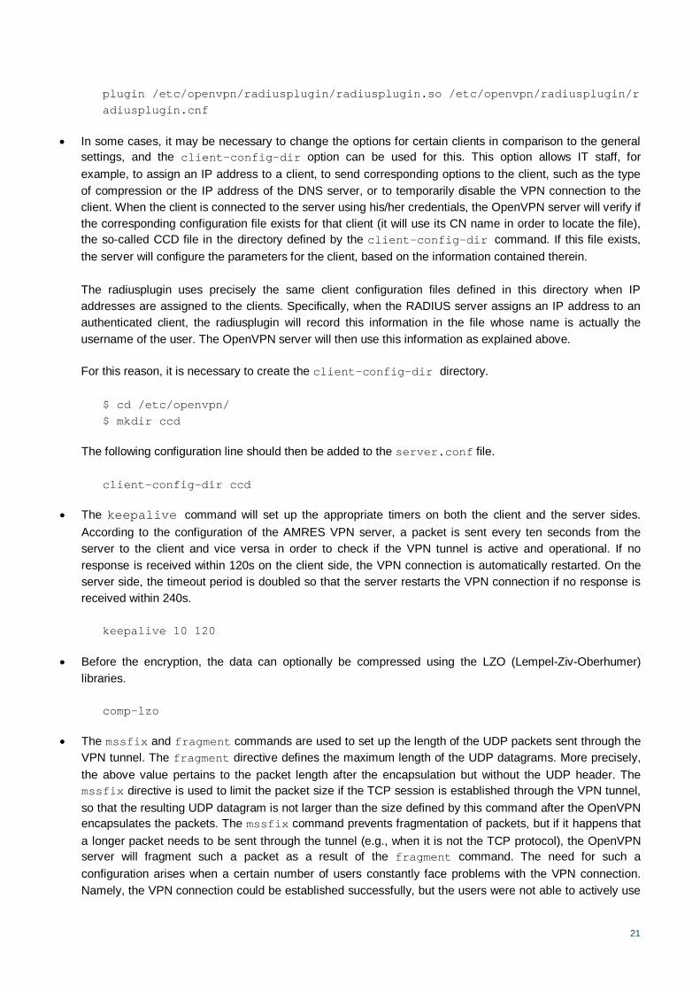
plugin /etc/openvpn/radiusplugin/radiusplugin.so /etc/openvpn/radiusplugin/radiusplugin.cnf
In some cases, it may be necessary to change the options for certain clients in comparison to the general settings, and the client-config-dir option can be used for this. This option allows IT staff, for example, to assign an IP address to a client, to send corresponding options to the client, such as the type of compression or the IP address of the DNS server, or to temporarily disable the VPN connection to the client. When the client is connected to the server using his/her credentials, the OpenVPN server will verify if the corresponding configuration file exists for that client (it will use its CN name in order to locate the file), the so-called CCD file in the directory defined by the client-config-dir command. If this file exists, the server will configure the parameters for the client, based on the information contained therein.
The radiusplugin uses precisely the same client configuration files defined in this directory when IP addresses are assigned to the clients. Specifically, when the RADIUS server assigns an IP address to an authenticated client, the radiusplugin will record this information in the file whose name is actually the username of the user. The OpenVPN server will then use this information as explained above.
For this reason, it is necessary to create the client-config-dir directory.
$ cd /etc/openvpn/ $ mkdir ccd
The following configuration line should then be added to the server.conf file.
client-config-dir ccd
The keepalive command will set up the appropriate timers on both the client and the server sides. According to the configuration of the AMRES VPN server, a packet is sent every ten seconds from the server to the client and vice versa in order to check if the VPN tunnel is active and operational. If no response is received within 120s on the client side, the VPN connection is automatically restarted. On the server side, the timeout period is doubled so that the server restarts the VPN connection if no response is received within 240s.
keepalive 10 120
Before the encryption, the data can optionally be compressed using the LZO (Lempel-Ziv-Oberhumer) libraries.
comp-lzo
The mssfix and fragment commands are used to set up the length of the UDP packets sent through the VPN tunnel. The fragment directive defines the maximum length of the UDP datagrams. More precisely, the above value pertains to the packet length after the encapsulation but without the UDP header. The mssfix directive is used to limit the packet size if the TCP session is established through the VPN tunnel, so that the resulting UDP datagram is not larger than the size defined by this command after the OpenVPN encapsulates the packets. The mssfix command prevents fragmentation of packets, but if it happens that a longer packet needs to be sent through the tunnel (e.g., when it is not the TCP protocol), the OpenVPN server will fragment such a packet as a result of the fragment command. The need for such a configuration arises when a certain number of users constantly face problems with the VPN connection. Namely, the VPN connection could be established successfully, but the users were not able to actively use

22
it. It has been established that all users who faced this problem were establishing the local connection with the Internet through the same Internet service provider that reduced the MTU (Maximum Transmission Unit) value on its devices below the standard value. Thus, the problem has been successfully solved in the manner described above.
fragment 1200 mssfix 1200
The AMRES VPN server is configured to send the routes for the network ranges available through the VPN tunnels to its clients. This has been enabled through the push command. The VPN server sends the routes to the AMRES IP address ranges. The server also sends a route to the IP address of its external interface, 147.91.a.b, which redirects packets at that address to the local gateway of the VPN client device rather than sending them through the VPN tunnel. The reason behind such a configuration lies in the fact that the address of the external interface of the VPN server belongs to the AMRES address range, and it is through this address that the VPN connection is established.
push "route 147.91.0.0 255.255.0.0" push "route 147.91.a.b 255.255.255.255 net_gateway 0.0.0.0"
The OpenVPN is run as a process (daemon), and for security reasons, the OpenVPN process is assigned to the user nobody and the group nogroup, by the commands user and group, which reduces privileges. In this way, even if a remote attacker managed to compromise the OpenVPN process, the attacker will be assigned the privileges of the user nobody and not of the user root. However, during the next running of the process, the user nobody will not have sufficient privileges to access certain resources and that is why the persist-tun and persist-key directives need to be added. These prevent the resetting of the tun interface on the next running of the process so that certain keys for reading protected files do not have to be entered again.
user nobody group nogroup daemon persist-key persist-tun
Due to the log-append directive, the OpenVPN process will enter the debug information and messages in the said file. New log information will be appended and the old information will not be overwritten. The status directive defines the entering of information about the status of the current VPN connection in the said file. This information may be very important when monitoring the OpenVPN process and resolving any problems.
status /var/log/openvpn-status.log log-append /var/log/openvpn.log
The verb directive defines the level of detail of the information entered in the log files. Empirical research has shown that level 5 provides sufficient information to resolve problems related to the establishment of connections that tend to be the most frequent.
verb 5
Other configuration lines may be commented out (by adding # at the beginning of the line).

23
2.1.3 Configuring the VPN Client
Following the configuration of the VPN server, the VPN client also needs to be configured. In order to authenticate the server, the CA certificate needs to be copied to the client. The client should also contain the same ta.key key as the server. Since the clients are authenticated by the username and password, it is necessary to specify the auth-user-pass directive. Other settings required in order to establish successful communication between the VPN and the server configured in the manner were explained in the previous chapter and include the following: the specification of the use of the TUN interface; the encapsulation of packets into the UDP protocol; the fragmentation and the type of compression. The content of the configuration file of the VPN client is presented below.
client fragment 1200 mssfix 1200 dev tun proto udp remote vpn-example.amres.ac.rs 1194 resolv-retry infinite nobind persist-key persist-tun ca ca.crt ns-cert-type server tls-auth ta.key 1 comp-lzo verb 1 auth-user-pass pull explicit-exit-notify
The vpn-example.amres.ac.rs name is the DNS name for the external network card of the VPN server - 147.91.a.b.
2.2 The RADIUS Infrastructure
The AMRES VPN service relies on the RADIUS infrastructure, through which the authentication, authorisation, and accounting activities are performed. Since the AMRES solution is implemented using the FreeRADIUS platform, this chapter deals with setting the basic modules of the FreeRADIUS server for the purposes of configuring the TLR server. It also provides an example of configuring an institution’s RADIUS server, again by using the FreeRADIUS platform.
It is presumed, in this case, that the FreeRADIUS program has been installed and that there are no other changes except those presented below.
The FreeRADIUS server is configured by modifying certain configuration files. The location of these files depends on the way in which the FreeRADIUS package has been installed.

24
If the standard FreeRADIUS package is installed on an operating system distribution, the configuration files will be located in the /etc/raddb directory of CentOS, or in the /etc/freeradius directory of the Ubuntu operating system.
If the FreeRADIUS program is compiled and installed using the configure, make, make install commands, the configuration files will be located in the /usr/local/etc/raddb directory.
It is assumed, hereinafter, that the configuration directory for FreeRADIUS is /usr/local/etc/raddb.
The FreeRADIUS server configuration is logically divided into different configuration files. These files are modified in order to configure certain functions, components, and modules for FreeRADIUS. The main configuration file is radiusd.conf, into which the contents of other configuration files are included by the $INCLUDE command. The configuration files significant for setting the server for the purposes of the solution presented are:
proxy.conf – used to define the domain for which the requests will be forwarded to other RADIUS servers;
clients.conf – a file in which clients of the RADIUS server are defined. Any accessing device that is supposed to send requests to the FreeRADIUS server must be defined in this file. It can be a network device, a VPN server, another RADIUS server, etc. A shared secret for each client is defined in this file, and it must also be defined on the relevant device. The shared secret enables secure communication between the device and the FreeRADIUS server;
sql.conf – contains the sql module configuration. All the necessary settings for connecting and using the sql database are contained in this file;
virtual servers – these servers enable a larger number of independent RADIUS services to be configured on the FreeRADIUS platform. A virtual server is created in the /sites-available directory and activated by creating a link in the /sites-enabled directory. After the FreeRADIUS server has been installed, two virtual servers are activated: default and inner-tunnel. The default virtual server is used for typical requests, while the inner-tunnel is used for configuring the EAP method. Here, only the default virtual server is used;
users – located in the FreeRADIUS configuration directory. The contents of this file can be used for authentication and authorisation purposes. User-related settings are entered in this file.
2.2.1 Configuring the Top Level RADIUS Server
This chapter explains the configuration files that are necessary for setting up the TLR server. It should be taken into account that the TLR server is a proxy RADIUS server, that IP addresses are assigned to authenticated VPN users through this server, and that it is used to process data on the activity of VPN users.

25
2.2.1.1 VPN Virtual Server
The configuration file of the virtual server contains the following sections: listen; authorize; authenticate; post-auth; pre-proxy; post-proxy; preacct; accounting; and session. The basic procedure of processing the incoming authentication request comprises the following steps:
when the FreeRADIUS server receives a user authentication request (Access-Request), the request is first processed in the authorize section of the virtual server. The modules defined in the authorize section determine the mechanism used for authenticating the user. The request can be processed additionally in this section;
after the authentication type has been determined, the request is sent to the authenticate section. A suitable subsection within this section will take over the request and conduct authentication;
following a successful authentication, the procedure reaches the post-auth section; the accounting section is in charge of processing the incoming accounting messages.
The TLR server should only forward the received authentication request to the RADIUS server of the client’s home institution. It is necessary to configure one virtual server that will process the authentication requests in this manner. For this purpose, in the /sites-available directory, the contents of the default configuration file is copied to a new vpn file.
The created configuration file is modified according to the configuration provided below.
$ cd /usr/local/etc/raddb/sites-available $ cp default vpn $ vi vpn
server vpn { authorize { preprocess auth_log chap mschap digest suffix eap files expiration logintime pap } authenticate { Auth-Type PAP { pap } Auth-Type CHAP { chap } Auth-Type MS-CHAP { mschap } digest unix eap }
26
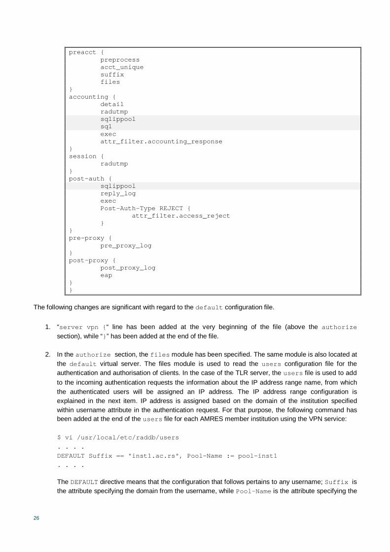
preacct { preprocess acct_unique suffix files } accounting { detail radutmp sqlippool sql exec attr_filter.accounting_response } session { radutmp } post-auth { sqlippool reply_log exec Post-Auth-Type REJECT { attr_filter.access_reject } } pre-proxy { pre_proxy_log } post-proxy { post_proxy_log eap } }
The following changes are significant with regard to the default configuration file.
1. “server vpn {“ line has been added at the very beginning of the file (above the authorize section), while “}” has been added at the end of the file.
2. In the authorize section, the files module has been specified. The same module is also located at the default virtual server. The files module is used to read the users configuration file for the authentication and authorisation of clients. In the case of the TLR server, the users file is used to add to the incoming authentication requests the information about the IP address range name, from which the authenticated users will be assigned an IP address. The IP address range configuration is explained in the next item. IP address is assigned based on the domain of the institution specified within username attribute in the authentication request. For that purpose, the following command has been added at the end of the users file for each AMRES member institution using the VPN service:
$ vi /usr/local/etc/raddb/users . . . . DEFAULT Suffix == "inst1.ac.rs", Pool-Name := pool-inst1 . . . .
The DEFAULT directive means that the configuration that follows pertains to any username; Suffix is the attribute specifying the domain from the username, while Pool-Name is the attribute specifying the
27
IP address range from which IP addresses are assigned to clients. Hence, any user whose domain is inst1.bg.ac.rs will get an IP address from the address range named pool-inst1.
3. In the post-auth section, there are configuration lines pertaining to the assignment of IP addresses to authenticated VPN clients.
Note: the rlm_ippool module had been used initially for assigning the IP addresses to VPN users. However, a problem can regarding the assignment of the same IP address simultaneously to different VPN users, which is why the assignment of IP addresses to VPN clients has been implemented by using the rlm_sqlippool module. For that purpose, it is necessary to add the following configuration lines in the radiusd.conf file at the modules section.
$ vi /usr/local/etc/raddb/radiusd.conf
. . . . modules { . . . . $INCLUDE sql.conf $INCLUDE sqlippool.conf . . . .
The sql.conf file located in the configuration directory of the FreeRADIUS server (/usr/local/etc/raddb/sql.conf) is a configuration file of the sql module, and it contains all the configuration parameters necessary to establish the connection with the corresponding SQL database for any purpose. The TLR server is used for assigning IP addresses to VPN clients and for accounting, i.e., the same SQL database contains the table of the IP address range allocated to the users and the tables that are filled in the course of monitoring user activity.
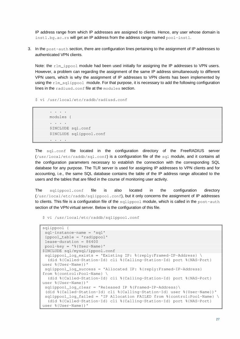
The sqlippool.conf file is also located in the configuration directory (/usr/local/etc/raddb/sqlippool.conf), but it only concerns the assignment of IP addresses to clients. This file is a configuration file of the sqlippool module, which is called in the post-auth section of the VPN virtual server. Below is the configuration of this file.
$ vi /usr/local/etc/raddb/sqlippool.conf
sqlippool { sql-instance-name = "sql" ippool_table = "radippool" lease-duration = 86400 pool-key = "%{User-Name}" $INCLUDE sql/mysql/ippool.conf sqlippool_log_exists = "Existing IP: %{reply:Framed-IP-Address} \ (did %{Called-Station-Id} cli %{Calling-Station-Id} port %{NAS-Port} user %{User-Name})" sqlippool_log_success = "Allocated IP: %{reply:Framed-IP-Address} from %{control:Pool-Name} \ (did %{Called-Station-Id} cli %{Calling-Station-Id} port %{NAS-Port} user %{User-Name})" sqlippool_log_clear = "Released IP %{Framed-IP-Address}\ (did %{Called-Station-Id} cli %{Calling-Station-Id} user %{User-Name})" sqlippool_log_failed = "IP Allocation FAILED from %{control:Pool-Name} \ (did %{Called-Station-Id} cli %{Calling-Station-Id} port %{NAS-Port} user %{User-Name})"

28
sqlippool_log_nopool = "No Pool-Name defined \ (did %{Called-Station-Id} cli %{Calling-Station-Id} port %{NAS-Port} user %{User-Name})" }
The highlighted lines are of significance. Within this configuration file, it is the sql module defined in the sql.conf file that is being called. A table named radippool has been defined as the table into which the range of IP addresses to be assigned to VPN clients will be entered (ippool_table); it has been defined in the corresponding MySQL database, as is explained below. The time of assignment of addresses has also been defined within the lease-duration parameters (in this example, it is configured to twenty-four hours). The parameter based on which a unique IP address is assigned (pool-key) is the username (User-Name).
The ippool.conf configuration file (that is called by using the $INCLUDE command) defines the different queries at MySQL base. These serve to assign IP addresses to clients and to return/release the addresses in various cases. Special attention should be paid to the configuration of this file as it may happen that the syntax used does not suit the version of the MySQL base, which is why certain functions would not be executed successfully (e.g., releasing the IP address from the client who terminated the VPN connection). In that case, it is necessary to modify the queries so that the syntax corresponds to the version of the MySQL database being used.
Note: the /usr/local/etc/raddb/sql/mysql/ippool.sql schema is used to create the radippool tables.
$ mysql -u root -p radius < /usr/local/etc/raddb/sql/mysql/ippool.sql
Below is the configuration of the sql.conf file.
$ vi /usr/local/etc/raddb/sql.conf
sql { database = "mysql" driver = "rlm_sql_${database}" server = "147.91.x.y" login = "radiusUSER" password = "radiusPASS" radius_db = "radius" acct_table1 = "radacct" # table that is used for accounting acct_table2 = "radacct" # table that is used for accounting postauth_table = "radpostauth" authcheck_table = "radcheck" authreply_table = "radreply" groupcheck_table = "radgroupcheck" groupreply_table = "radgroupreply" usergroup_table = "radusergroup" deletestalesessions = yes sqltrace = no sqltracefile = ${logdir}/sqltrace.sql num_sql_socks = 5 connect_failure_retry_delay = 60 lifetime = 0 max_queries = 0 nas_table = "nas" $INCLUDE sql/${database}/dialup.conf }

29
The parameters of the MySQL database are defined in the sql section of the sql.conf file. The address ranges, from which authenticated users are assigned IP addresses based on the domain of their institution, are defined in radipool table of the radius database created in the MySQL database. Each institution has its own address range, and each of these ranges has a name assigned to it. The names of IP address ranges are mapped with the domains of the institutions in the users file (explained in item 2). The MySQL database is installed on the host with IP address 147.91.x.y (directive: server = "147.91.x.y"). The username and password for accessing the database are defined by the variables, login and password, and are created for these purposes only. The variable radius_db bears the name of the database within which the radipool table has been defined (in this example, it is the radius database). Of course, for each member institution, it is necessary to define a range of IP addresses in the radippool table that will be assigned to VPN users of that member institution.
An example of the radippool table is shown in the Figure below.
mysql> use radius Database changed mysql> select * from radippool; +----+--------------+-----------------+--------------+-----------------+------------------+---------------------+--------------------+--------------------+ | id | pool_name | framedipaddress | nasipaddress | calledstationid | callingstationid | expiry_time | username | pool_key | +----+--------------+-----------------+--------------+-----------------+------------------+---------------------+--------------------+--------------------+ | 1 | pool-inst1 | 10.8.1.1 | | | | NULL | | | | 2 | pool-inst1 | 10.8.1.2 | | | | NULL | | | +----+--------------+-----------------+--------------+-----------------+------------------+---------------------+--------------------+--------------------+
4. The sqlippool directive also needs to be added in the accounting section of the vpn virtual server. In this way, the RADIUS server is enabled to release a client’s IP address when the client terminates the VPN connection, so that the address can be assigned to another client.
Likewise, the configuration lines defining the manner in which the RADIUS server processes accounting messages about user activity are also specified in this section. The VPN server will send the user activity data to the TLR server, which will send them to the appropriate SQL database in accordance with the information from this section. This is why the sql configuration line in the accounting section is important. It is actually the section inside the configuration file of the sql module, i.e. sql.conf, which has been explained in detail in item 3 (the same sql module is being called).
Therefore, it is the same MySQL database in which the abovementioned radius database is configured. Also, it is in this database that the radacct is created, in which the user activity is entered.
Note: the /usr/local/etc/raddb/sql/mysql/schema.sql schema is used for creating the table, for the purposes of the accounting mechanism.

30
$ mysql -u root -p radius < /usr/local/etc/raddb/sql/mysql/schema.sql
The sql/${database}/dialup.conf configuration file, which is included at the end of this section, defines the data to be entered into the radacct table. This file already exists in the specified location and it is included, by default, in the sql.conf configuration file. It is possible to modify it as needed.
All the other configuration parameters are standard.
5. In order to activate the vpn virtual server, it is necessary to create a link to the vpn configuration file at the /sites-enabled directory.
$ cd /usr/local/etc/raddb/sites-enabled $ ln –s /usr/local/etc/raddb/sites-available/vpn
2.2.1.2 clients.conf
The TLR server receives authentication requests from the VPN server only, which is why its clients.conf file contains only the configuration concerning the VPN server, as shown below.
$ vi /usr/local/etc/raddb/clients.conf
. . . . ## AMRES VPN server client vpn-server { ipaddr = 147.91.c.d # IP address of internal interface of VPN server secret = pass # Shared secret defined on the VPN server shortname = OpenVPN nastype = other virtual_server = vpn }
It is very important to specify the vpn virtual server as the virtual_server, in which case, the requests coming from this client will be processed according to the configuration of the vpn virtual server. The shared secret, defined therein, is the same secret that has been defined in the radiusplugin.cnf configuration file in the course of configuring the VPN server (chapter 2.1.2.2).
2.2.1.3 proxy.conf
The proxy.conf configuration file is the module according to which the RADIUS server decides whether an incoming authentication request will be processed or forwarded to another server. For that purpose, the home_server_pool, home_server and realm parameters are defined. The home_server parameter is used for defining the individual RADIUS servers to which the authentication requests will be forwarded. The server defined here is grouped in the home_server_pool. The domains expected to be found in the incoming authentication requests are defined under the realm section. For a domain defined in the realm section, the corresponding home_server_pool is entered, containing the RADIUS servers to which the authentication requests sent for users with the specified domain will be forwarded.
31
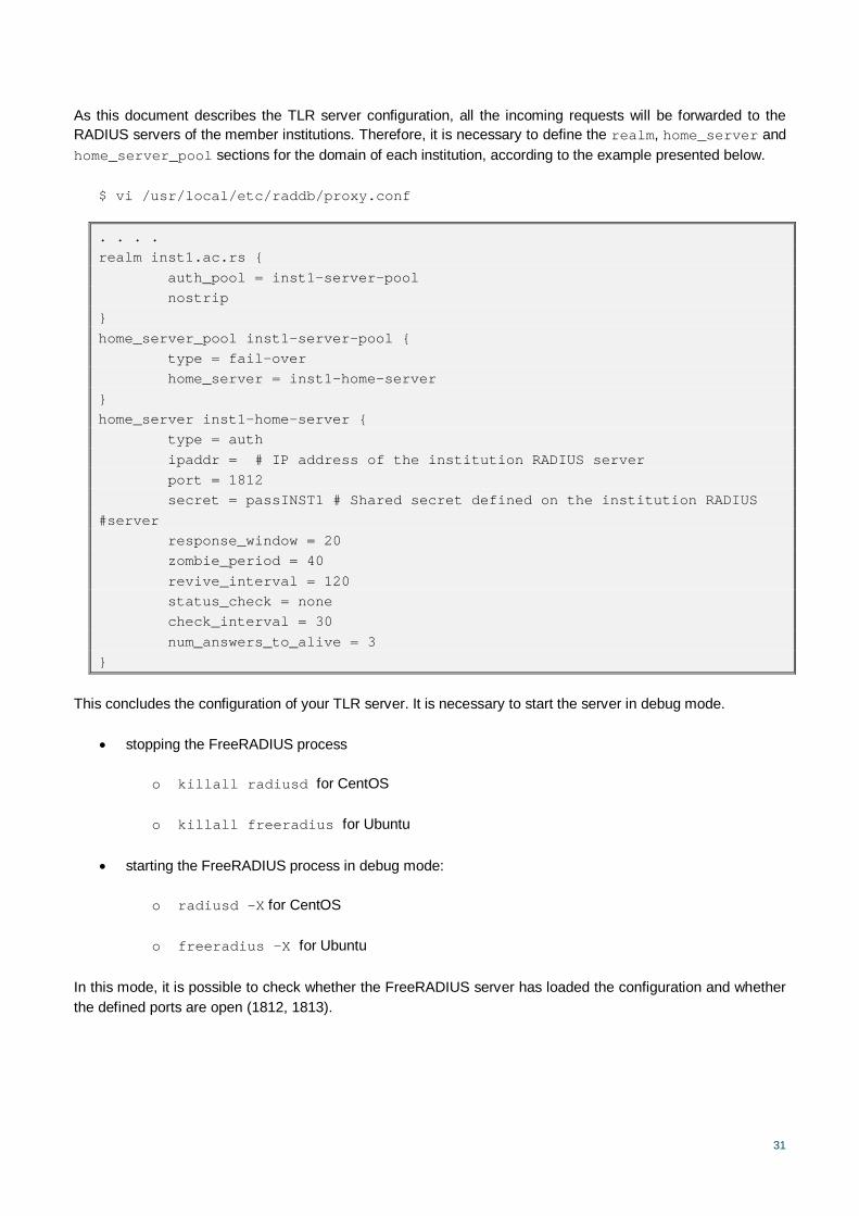
As this document describes the TLR server configuration, all the incoming requests will be forwarded to the RADIUS servers of the member institutions. Therefore, it is necessary to define the realm, home_server and home_server_pool sections for the domain of each institution, according to the example presented below.
$ vi /usr/local/etc/raddb/proxy.conf
. . . . realm inst1.ac.rs { auth_pool = inst1-server-pool nostrip } home_server_pool inst1-server-pool { type = fail-over home_server = inst1-home-server } home_server inst1-home-server { type = auth ipaddr = # IP address of the institution RADIUS server port = 1812 secret = passINST1 # Shared secret defined on the institution RADIUS #server response_window = 20 zombie_period = 40 revive_interval = 120 status_check = none check_interval = 30 num_answers_to_alive = 3 }
This concludes the configuration of your TLR server. It is necessary to start the server in debug mode.
stopping the FreeRADIUS process
o killall radiusd for CentOS
o killall freeradius for Ubuntu
starting the FreeRADIUS process in debug mode:
o radiusd –X for CentOS
o freeradius –X for Ubuntu
In this mode, it is possible to check whether the FreeRADIUS server has loaded the configuration and whether the defined ports are open (1812, 1813).

32
2.2.2 An Example of an Institution’s RADIUS Server Configuration
This chapter provides an example of the configuration of the FreeRADIUS server of an AMRES member institution taking part in the VPN service. The RADIUS server of the institution receives and processes the authentication requests of its users sent from the TLR server. Each institution keeps the data on its users in a database. The connection between the FreeRADIUS server and specific databases is outside the scope of this document. Here, an example is given of using the users file for authenticating the users. This chapter covers the configuration of all the relevant FreeRADIUS configuration files.
2.2.2.1 VPN Virtual Server
It is necessary to configure a virtual server that will process the authentication requests coming from the TLR server. To that end, the contents of the default configuration file is copied to a new vpn file in the /sites-available directory.
The configuration file, thus created, is modified according to the configuration provided below.
$ cd /usr/local/etc/raddb/sites-available $ cp default vpn $ vi vpn
server vpn { authorize { auth_log suffix eap files pap } authenticate { Auth-Type PAP { pap } Auth-Type CHAP { chap } Auth-Type MS-CHAP { mschap } unix eap } session { radutmp } post-auth { Post-Auth-Type REJECT { attr_filter.access_reject

33
} } pre-proxy { } post-proxy { eap } }
The following modifications are of importance as compared to the default configuration file.
1. At the very beginning of the file, the “server vpn {“ line is added, and ”}“ is added at the end of the file.
2. In the authorize section, the files module is specified. The same module is located in the default virtual server. The files module is used here for reading the users configuration file for the purpose of authenticating the clients. The username and password can be specified in this configuration file. Below is an example of the line that can be used for that purpose.
$ vi /usr/local/etc/raddb/users . . . . "alice" Cleartext-Password := "passme" . . . .
Hence, the user account defined above has alice as the username and passme as the password.
3. In order to activate the vpn virtual server, it is necessary to create a link to the vpn configuration file in the /sites-enabled directory.
$ cd /usr/local/etc/raddb/sites-enabled $ ln –s /usr/local/etc/raddb/sites-available/vpn
2.2.2.2 clients.conf
As the institution’s RADIUS server receives authentication requests from the TLR server only, it is necessary to also configure the TLR server in its clients.conf file, as follows.
$ vi /usr/local/etc/raddb/clients.conf
. . . .
##AMRES VPN client amres.vpn.radius { ipaddr = tlr.amres.ac.rs secret = passINST1 shortname = TLR nastype = other virtual_server = vpn }

34
It is very important to enter the vpn virtual server as the virtual_server parameter, because, in this case, the requests coming from the client will be processed according to the configuration of the vpn virtual server. The name tlr.amres.ac.rs is the DNS name of the TLR server, while the shared secret is the same one that has been defined for the RADIUS server of this institution in the proxy.conf file of the TLR server.
2.2.2.3 proxy.conf
As the described configuration is that of a member institution’s RADIUS server, all the received requests will be processed locally, so it is necessary to create only a local realm and specify in it that authentication, which is conducted locally. An example of the configuration of the proxy.conf file is presented below.
$ vi /usr/local/etc/raddb/proxy.conf
proxy server { default_fallback = no } home_server localhost { type = auth+acct ipaddr = 127.0.0.1 port = 1812 secret = testing123 response_window = 20 zombie_period = 40 revive_interval = 120 status_check = status-server check_interval = 30 num_answers_to_alive = 3 } realm inst1.ac.rs { authhost = LOCAL accthost = LOCAL User-Name = "%{Stripped-User-Name}" } realm LOCAL { } realm NULL { }
In this case, inst1.ac.rs is the domain of the institution whose RADIUS server has been configured.
35
3 Conclusion
This completes the configuration of the basic components of the AMRES VPN service. The service has been developed to enable the users of AMRES member institutions to access the academic network and utilise the offered services, even when they are outside their institutions. Of course, the end users must observe the VPN service terms and conditions. Once the VPN connection is established, the VPN user device becomes a part of the AMRES network, which is why the user must abide the rules defined in the Acceptable Use Policy (AUP) of the Academic Network of Serbia. These concern both the adequate protection of their computers and of all the activities within the AMRES network.
The VPN service relies on the RADIUS infrastructure that was developed and is used in the eduroam® service. In order for an institution to enable its users to access the VPN service, it needs to provide them with a username and password. Both the quality of data and the quality of the assignment, maintenance, and cancellation of identity must be satisfactory. Besides the username and password, a digital identity of a user must contain sufficient data to identify the real person using a certain username. Identities can only be assigned to persons who are connected to the home institution at a given time and they must be exclusively personal. All AMRES institutions participating in the eduroam® service meet these conditions. This minimises investment by AMRES institutions who wish to become users of the VPN service. On the other hand, AMRES provides full support to all of its members institutions interested in implementing their VPN solution.

36
References
[1 ] M. Feilner, N. Graf, “Beginning OpenVPN 2.0.9, Build and Integrate Virtual Private Networks using OpenVPN”
[2 ] Jan Just Keijser, “OpenVPN 2 Cookbook” [3 ] S. Frankel, P. Hoffman, A. Orebaugh, R. Park, “Guide to SSL VPNs” [4 ] Dirk van der Walt, “FreeRADIUS Beginner’s Guide [5 ] OpenVPN: http://openvpn.net/index.php/access-server/docs.html [6 ] FreeRADIUS: http://freeradius.org/

37
Glossary
VPN Virtual Private Network RADIUS Remote Authentication Dial In User Service TLR Top Level RADIUS EAP Extensible Authentication Protocol SSL Secure Sockets Layer TLS Transport Layer Security PAP Password Authentication Protocol MSCHAPv2 Microsoft Challenge Handshake Auth Protocol version 2 LZO Lempel-Ziv-Oberhumer DH Diffie-Hellman CA Certificate Authority SQL Structured Query Language HMAC Hash-based Message Authentication Code AUP Acceptable Use Policy