Embed Size (px)
Citation preview

THE ILLUSTRATION OFLITHIC ARTEFACTS:
A GUIDE TODRAWING STONE TOOLS
FOR SPECIALIST REPORTSby Hazel Martingell and Alan Saville
ASSOCIATION OF ARCHAEOLOGICAL ILLUSTRATORS& SURVEYORS
LSS OCCASIONAL PAPER No. 3AAI&S TECHNICAL PAPER No. 9
1988

THE ILLUSTRATION OFLITHIC ARTEFACTS:
A GUIDE TODRAWING STONE TOOLS
FOR SPECIALIST REPORTSby Hazel Martingell and Alan Saville
ASSOCIATION OF ARCHAEOLOGICAL ILLUSTRATORS & SURVEYORS
THE LITHIC STUDIES SOCIETY
NORTHAMPTON 1988
ISBN 0 9513246 0 8ISSN 0950-9208

1
Introduction
This booklet, which owes its origins to a series of notes first published in Lithics (Martingell 1980, 981, 1982, and 1983), is intended to serve as a guide to the illustration of lithic artefacts. It is restricted in focus to types of prehistoric flint and stone tools commonly found in Britain, though many of the principles involved will have a much wider application. The booklet is aimed primarily at illustrators who are not themselves lithic specialists but who are in the position of preparing drawings to accompany specialist lithic reports for publication in archaeological journals and books. Such a guidebook seems necessary because the recent growth of interest in lithic studies is leading to an increase in the amount of lithic illustration being undertaken by more and more illustrators. At the same time the development of specialist knowledge in the field of lithics is making greater demands on the illustrator to record ever more detail, often by the use of special conventions and symbols. The experienced lithic illustrator mayf ind little herein that is new, but it is hoped that the novice illustrator, or the practising illustrator turning to flint and stone artefacts for the first time, will be helped by the following points and guidelines. This booklet is also aimed at lithic specialists themselves, and at non-specialist excavators and editors who may be involved in the commissioning of, and in overseeing the publication of, lithic reports. Flint and stone artefacts are usually illustrated in a style that gives a three-dimensional impression, a form of representation which supplies the maximum amount of information about the technology of an artefact in each single drawing. While the authors would advocate and seek to encourage the highest possible standard of illustration, it must be admitted that the very best examples of the almost fully ‘lifelike’ three-dimensional style – for example as achieved in the woodcut engravings by Swain (in Evans 1897), or in pen-and-ink by Dauvois (1976) – involve a degree of artistry and commitment which may be beyond the average illustrator or at least not cost-effective within post-excavation budgets. Constraints on budgets may even require at times the production of ‘open’ drawings without infilling the details of flake scars. Nevertheless, whatever the style, it is necessary to emphasize the overriding need for accuracy in this as in other aspects of archaeological drawing. A group of superficially similar implements, such as a series of leaf-shaped arrowheads from the same site, will contain differences of detail which the specialist will need to see reflected in the illustrations, and which will be necessary to enable the reader to comprehend visually the specialist’s written account. Research workers and museum staff will require accurate illustrations to check against the artefacts themselves or against catalogue notes; all too often either the artefacts or the original records can become mislaid, and then the illustrations are vital in re-establishing a provenance or re-uniting an assemblage. Ideally,
illustrations should be an essential part of a catalogue of lithic artefacts, though in this case not all drawings will necessarily be finished to publication standard.
Consistencies of style, of orientation (Fig. 1), of conventions, etc., are important, as well as accuracy, for conveying the character of a particular assemblage and for creating the all-important visual harmony of a set of drawings. The specialist will want the lithic illustrations to display the overall impression of the nature of the assemblage being analysed, and good illustrations in this regard will be far more successful than many pages of descriptive text.
This guidebook has been kept intentionally brief to reduce costs and increase availability, but is designed to contain enough information for the intending lithic illustrator to proceed effectively. Those seeking more detailed and technical guidance and a wider range of model illustrations should consult the works by Addington (1986) and Dauvois (1976).
Working with the lithic specialist
The best drawings are achieved when there is collaboration between the illustrator and the lithic specialist. This sounds obvious, but it is all too common for such collaborations to founder under the pressures of publication deadlines, disagreements between specialists and excavators, and so on. Ideally the illustrator should not begin work on the illustration of a group of lithic artefacts until preliminary notes on the drawings are supplied by the specialist. Certainly the illustrator should never prepare publication drawings for an excavator before a lithic specialist has been engaged - otherwise there is a risk that the illustrations will have to be completely redrawn or that entirely different artefacts will be selected for illustration.
Preliminary notes from the lithic specialist should indicate the level of illustration, whether fully detailed or schematic; the orientation of each artefact relative to an upright page; the number and position of views and sections; the position and nature of any special features such as edge gloss; and the full reference number and site code of each object. All drawings should be examined by the specialist at the pencil stage, so that if any corrections are necessary they can be made before inking.
Understanding the specialist’s requirements can be difficult, if not impossible, without some knowledge of basic lithic technology and typology (Fig. 1). Background reading of introductory texts will help (e.g. Bordaz 1970 and 1971; Pitts 1980; Timms 1974; Watson 1968), but is no substitute for the observation of a demonstration of flint-knapping techniques by a modern practitioner. Such demonstrations are increasingly common as a component of day-schools organized by archaeological groups and university extra-mural departments. Familiarity with

2
the terminology of flaking used by the specialist - such terms as striking platform, bulb of percussion, bulbar scar, faceted butt, etc. (see Fig. 1) - will be very useful to the illustrator. There are clear differences in quality between the drawings of those illustrators who understand the principles of knapping and those who do not.
Equally, the specialist must be aware of the needs and level of knowledge of the illustrator and of the constraints under which illustrators often work. For example, the specialist may have access to published or unpublished work unavailable to the illustrator, and should supply photocopies of relevant drawings. Nor need communication between specialist and illustrator be one-way, since feedback from the illustrator can often improve the specialist’s understanding of details on a particular artefact.
Reading the artefact
A single lithic artefact may have several different types of surface area visible, each requiring separate stylistic treatment. For example, there may be natural fractures resulting from burning or freeze-thaw climatic conditions, which must be distinguished on the drawing from humanly produced facets. Areas of the outer skin (cortex) of a flint nodule or the smooth
outer surface of a stone pebble may remain on some artefacts, and are usually represented by stippling (see Fig. 2). To be able to indicate the humanly struck areas on worked flint, which are normally apparent as negative flake beds or scars, it is essential to understand the direction of each flake removal. Flint fractures conchoidally, that is in a manner resembling the curved, concentrically ribbed surface of some shells. In other words, from the point of impact or percussion where the hammer strikes the flint surface, a series of concentric ripples are formed which are often visible both on the bulbar surface of the struck flake and on the negative flake scar left on the core or implement being worked. These ripples must be recorded to indicate the direction of flaking involved, and are usually drawn in continuous curved lines, the best effect being obtained with a split-nib pen that allows a variable line thickness (Fig. 3).
Some implements, like piercers, may comprise simple flakes on which little or no readily visible modification has taken place, while in other cases - a barbed-and-tanged arrowhead for example - a flake may be very elaborately retouched into the required form. Such elaborate retouch or secondary working may involve very small, precise flake removals, for which it is important to record the exact direction of flaking. With some implement types, such as end
Fig. 1 A selection of outline drawings to indicate points of artefact typology, terminology and orientation. Not to scale.

3
scrapers, the direction of retouch at the scraping edge will probably be apparent even on a poor illustration, but for more complex implements or cores the careful distinguishing of the direction of flake removals is crucial.
The flake ripples will not always be readily apparent (though they may ‘emerge’ under magnification or by holding the piece of flint sideways to a light source) and it is often necessary to indicate them somewhat schematically. Cracks and crystal pockets which occur naturally in flint should be shown realistically wherever possible, as these faults can cause a change in direction of flake ripples, and their inclusion can explain the presence of an irregular flake scar. If such faults are profuse, however, a balance must be kept in the drawing to avoid obscuring the details of flaking and retouch.
As important as the direction of flake removals is the sequence in which those removals have taken place on an artefact. The most recent negative flake scar on
an implement will be complete, as the drawing will reveal by the presence of a negative bulb of percussion.
Previous flake scars will be truncated to a lesser or greater extent (Fig. 4). The way in which flake scars are truncated and shaded will indicate the order of flake removals (Fig. 5) and a successful drawing will allow the flaking ‘history’ of an artefact to be read.
When an artefact becomes ‘rolled’, normally by the natural friction created by movement in water or gravel for long periods, it loses the sharpness of the ridges between flake scars and flake faces which is a feature of freshly struck pieces. These blunted and blurred features must be faithfully reflected in
the drawing when ‘rolled’ artefacts are illustrated, normally by leaving open the intersection of the flake scars (Figs. 9 and 18), or by depicting the intersection as a dashed or stippled line rather than a solid one.
All lithic flake tools have an under surface (bulbar or ventral) and an upper surface (dorsal). Normally only the dorsal surface is illustrated, together with a side view or a cross-section or profile. This is because the secondary working or retouch is most frequently
Fig. 4 Complete and truncated flake scars: a) complete scar with progression of ripples from very curved at the base to shallow at the top; b) scar with bulbar end removed leaving an area of shallow ripples; c) scar with distal end removed leaving the curved ripples in the area of the negative bulb; d) scar truncated longitudinally. Original drawing reduced by 50%.
Fig. 2 Flint flake showing the contrasting depiction of natural features and humanly-produced effects.Drawn at 1:1 for reproduction at 1:1
Fig. 3 Types of line used for infilling flake detail according to raw material and surface condition. The broken and jagged lines would be used on stone rather than flint, to suggest the coarser quality and uneven surfaces.Printed at the scale at which drawn.

4
restricted to the dorsal surface, while the ventral surface simply comprises a single, positive, flake surface. The same applies to totally unretouched pieces, since the chief interest of the artefact probably will lie in the pattern of negative flake scars forming the dorsal surface.
Side views and profiles are placed directly alongside the dorsal view. There has in the past been considerable variation in which side of the artefact the accompanying side view has been placed against, and in which direction it was shown to face. Such variation becomes extremely confusing if there is inconsistency within a given set of drawings. (For an example of this kind of inconsistency see Saville 1981a, where the use of variable positioning by different illustrators has created an odd effect once the drawings have been mounted together.) In fact, unless a standardized procedure for positioning views is employed, the reader can never be entirely sure which side view is which. It is recommended here, therefore, that the so-called ‘American projection’ of aspect conventions, as shown in Fig. 6, is followed in all cases. Any deviation from this system should be carefully labelled to show which view is being depicted.
Vertical cross-sections are placed to the right of the dorsal w, and centrally between the dorsal and ventral views if both are drawn. Horizontal cross-sections can be placed above, below, or to the side of the dorsal view
according to where they fit best in a particular instance. The cross-section of a particular part of an implement, such as the tip of a piercer (Fig. 22), should be placed alongside the position of the section, with link-lines if necessary to make the relationship clear.
The colour of an artefact, where relevant, is described in the text and not by the illustration.
Fig. 5 A fragmentary pick (flint) used as an example of the analysis of the order of flake removals. The flatter, ventral surface (view I) was probably the first to be flaked and the numbers 1-11 show the possible order of removals, with 0 being the only remainder of the original bulbar surface. It can be seen that flake scars 1-11 are all truncated at their proximal ends, lacking negative bulbs of percussion. This truncation was caused by the four main steep removals from the dorsal surface (view 2a). The sequence of these large scars on the dorsal surface can be determined since flake scar B invades A and therefore postdates it, similarly scar D postdates C. Flake scar X, struck from the extremity of the implement, predates removals B, C, and D, each of which truncates it. The final stage of flaking involved the removal of small trimming flakes along the edges of the ventral surface (view 3), and these retain their negative bulbs of percussion. The publication drawing of this implement would comprise views 2a and 2b, views 1 and 3 being included here only to demonstrate the kind of analysis which would take place in the mind of the illustrator during the process of drawing the implement. Despite the overall similarity in the way in which the flake scars are depicted in views 2a and 2b, it is still possible to determine the sequence of flake removals from the drawing, showing that the illustrator has understood the way in which the implement has been flaked, thus in turn allowing the flaking history to be legible to the viewer. Drawn at 1:1 for reproduction at 2:3.
Fig. 6 The aspect conventions for illustrating various views of the same artefact. This system, know as orthographic or American projection, requires each new view to have the same surfaces adjacent. If the artefact were a flake, then A would be the dorsal surface and B the bulbar one.

5
The same is normally true of variations in surface colour occurring on a single artefact; in the case of flint artefacts such variation will usually be post-depositional and of no significance for the original manufacture and use of an implement. Colour-banding or variegation on stone implements, where this is thought to relate to the original selection of raw material, may need to be depicted (e.g. Roe 1968, fig. 36a), but can also be achieved inexpensively by publication of a monochrome photograph to complement a drawing (e.g. Roe 1985, figs. 8-9).
Practical Illustration Lithic artefacts are normally drawn at actual size
(1:1), except in the case of very small implements, like some microliths, which may be drawn at twice lifesize (2:1). The subject of reduction is discussed further in a following section. It should be noted that there is a school of thought which advocates the drawing of almost all lithic artefacts at twice lifesize, to permit easier depiction of finer detail and to allow substantial reduction to publication size to ‘crispen’ the image. This practice has been the rule in the archaeological drawing-office of the Department of the Environment (now English Heritage) at Fortress House, from where many influential illustrations have emanated (e.g. drawings of flint artefacts in Saville 1981a and Wainwright 1979). The technique relies on the availability of mechanical visualisers, however, without which the production of numerous enlarged drawings is too time-consuming to be practical.
Assuming the artefact is to be drawn at actual size, and assuming that the orientation has been determined from the specialist’s instructions or by
reference to normal conventions (see below), the following sequence of drawing stages may be adopted.
1. Place the artefact flat on the drawing surface (whether plain paper, graph-paper, or tracing- paper or drawing-film over graph-paper), if necessary steadying it with a wedge of ‘Blu-tack’. Avoid undue pressure on delicate flint artefacts when using ‘Blu-tack’; longitudinally curved pieces can easily snap when pressed against the hard surface of a drawing board.
2. With the lead of a pencil held perpendicular to the drawing surface and vertically positioned against the side of the artefact, draw carefully around the edge to achieve the outline (Fig. 7a). Before continuing, check the outline by holding a set-square upright against various positions around the artefact’s perimeter. Take care to avoid damaging the edges of delicate artefacts with the lead of the pencil; if necessary use a series of dots on the paper to key in the main features of the outline, determining their position with an .upright set-square set against the edge of the artefact, then join up the dots by eye.
3. Key in on the drawing the junctions of the main flake removals on the surface to be illustrated at the point where they intersect the outline (Fig. 7b), again using a set-square if necessary.
4. Place a sheet of rigid perspex (or glass) over the artefact, supporting it on suitable props to bring it flush with the surface of the artefact and parallel to the surface of the board. Trace the inner ridges between the flake scars and any other surface details, either directly on to the perspex, or on to acetate drawing film taped to its surface (Fig. 7c). The tracing may be easier if the surface details of the artefact
Fig. 7 Stages in the illustration of the dorsal surface of a flake (see text for details).

6
have previously been highlighted by running a soft pencil directly along the flake ridges, etc. (Such marks should be removed before returning the artefact to the specialist!)
5. Transfer the internal details on to the paper with the outline (Fig. 7d), using a light-box if necessary. This stage can be avoided by using the same transparent sheet for the outline and the tracing. Note that not every illustrator will choose to use the perspex sheet technique, developed by one of us (H.M.) as a rapid method for producing accurate drawings. The technique is perhaps most useful on pieces with complex retouch or where there is a lot of depth to be compressed into the horizontal plane. Other illustrators prefer to measure numerous key relationships, sometimes using a compass to plot ridge junctions by intersecting arcs, while experienced illustrators often work mainly by eye: see Addington (1986, 56).
6. Check any doubtful relationships between the surface details by measuring from object to drawing using dividers, callipers, or slide-gauge. Remember to allow for the effect of perspective when dealing with artefacts which have a surface exhibiting substantial vertical variation.
7. Continue the drawing by adding the ripples within the scars, and any other areas of retouch, fine secondary working, cortex, etc., working by eye from object to drawing and using dividers etc. where necessary (Fig. 7d). It is conventional to assume, when shading, that objects are illuminated from the top left-hand corner of the page; it will help to light the artefact in this way while composing the illustration. This lighting convention has two major implications, firstly, for the implement as a whole, principal light areas will be on the top left-hand surface of the object, and all the shadows will build up on the lower right-hand areas; secondly, for each individual flake scar, the darker, more shadowy zone will be immediately below the ridge at the upper or left edge of the scar, depending on the orientation of the scar and its relative depth. To repeat this light-to-shade effect on the illustration it will be necessary to begin the shading/ripple lines filling in the surfaces of the negative flake scars with the thick end of the line starting from the ridge between two scars, and then ‘feathering’ this line off to fade over the light areas. Lines are drawn closer together across areas in shadow and further apart on lighter surfaces. Cross-hatching should be avoided. It usually looks better if wider, flatter arcs are used for the ripple lines furthest from the point of impact or the edge of the artefact.
8. If a ventral (or bulbar) view is also required, the outline can be obtained by tracing from the drawing of the dorsal view on to transparent paper/film, then reversing this and drawing the internal d:etail of the ventral view on the other side of the sheet.
9. The initial stage of drawing a side view is to establish on the paper/film an accurate rectangle within which the view must fit. The top and bottom lines of
the rectangle are obtained by extending sideways the dimensions of the dorsal view or by tracing from it. The former is easily done if using a graph base for the drawing; if using paper then parallel lines can be projected using a set-square. The sides of the rectangle are obtained by measuring the maximum thickness of a symmetrical artefact, or the maximum vertical height of an assymetrical artefact when laid flat in the same position assumed for the dorsal drawing. The artefact can then be set on edge within the rectangle using ‘Blu-tack’ and the perimeter drawn around to record the outline. Especial care must be taken to check the accuracy of the side view outline with a set-square because of the optical distortion when viewing a deep object in this manner. The positions of the junctions of the flake scar ridges can then be keyed in from the dorsal view drawing, either by tracing or by extending parallel lines. If the ventral view is being drawn as well as the dorsal one, then the side view should be left until last so that ridge junctions can be keyed in from both of the face views. The rest of the ridge pattern on the side view can then be drawn using the perspex sheet technique or by measurement and reference to the face views. 10. When the pencil drawing is complete, with the identification number of the object clearly marked, it should be checked by the lithic specialist. (If illustrator and specialist are liaising at a distance then good quality photocopies of the drawings should be sent in the post -not the originals!) Any necessary alterations should then be made in pencil and the drawing given a further check before being carefully inked over. It will be a matter for arrangement between individual illustrators and specialists as to how much ancillary detail, such as complete shading, cortex stippling, etc., is necessary at the pencil stage. 11. In the final inking it is important not to lose any information from the pencil drawing by inaccurate or over-thick pen work. Always have i the actual artefact to hand when the inking is done; inking up in the absence of the artefact leads to ‘flat’, mechanical-looking drawings. Keep the surface of the ink drawing clean and free of ‘grease’ by working with a sheet of paper between the drawing hand and the drawing surface. In an attempt to render more sympathetically the texture of some flaked artefacts, particularly those of stone rather than flint, some specialists have opted to reproduce pencil rather than ink drawings in their final illustrations (e.g. drawings by P. O’Leary in Green 1984, 121-145). This has much to commend it, but does present technical difficulties in printing which can result in less, rather than more, detail appearing on the published page. Pencil drawings are also more vulnerable than inked ones to accidental erasure. 12. Lines linking the different views of the same artefact must be included. These should be short, horizontal lines, parallel to the base of the page, drawn with the rule, not free-hand. Link-lines (also known as connecting lines) are usually positioned at or near to the base of the illustrated artefact. Pairs of shorter horizontal lines, placed either

7
Fig. 8 Palaeolithic handaxe or biface (flint). As can be seen from the profile, the dorsal surface is domed while the ventral surface is much flatter: this is reflected in the differential shading of the flake scars on either face. One of the scars on the dorsal surface has a fault line (A) where the pattern of ripples has been interrupted, and this is shown in negative rather than by a solid line, which would confuse the scar pattern. On the ventral surface small patches of coarser material within the flint matrix are visible and have been shown by stipple. The conchoidal fracture pattern is not clear at these points (eg at B) and the scar ridges and surface ripples are therefore not shown.Drawn at 1:1 for reproduction at 2:3
side of the artefact at the appropriate point, are used to indicate the position of cross-sections. The use of additional link-lines, sometimes dashed, to relate to its location on the artefact a special view such as a faceted butt (Fig. 1, no. 10) or a core platform (Fig. 16), or a partial view such as an overhung retouched edge (Fig. 22), are optional, depending on the ‘readability’ of the overall illustration. When illustrating broken artefacts the break-edges should always be indicated by short continuation lines (also known as break-lines) at each side of the break, again drawn with a rule. Resist the temptation to reconstruct the shape of the missing area with a dashed line; such reconstruction on paper will be required by the specialist only in exceptional cases.
13. Cross-sections may be left open (e.g. Fig. 15), filled-in with oblique lines (e.g. Fig. 5), or can be fully blacked-in (e.g. Fig. 19), though the latter is inadvisable if the cross-sections are thick and/or numerous on the page, as too much solid black produces an unbalanced effect, which distracts attention away from the main views to the sections. Profile views designed to indicate the basic side aspect of an artefact are usually left open, except for a single line indicating the junction of the ventral and dorsal faces (e.g. Fig. 8), and it is the presence of this line which distinguishes a profile view from an open cross-section.
14. The numbering or labelling of the illustrated lithic artefacts on the drawing ideally should be the responsibility of the illustrator, not the specialist or the editor. Rub-down lettering (such as ‘Letraset’) is normally preferable to the use of stencils. Remember to ‘fix’ applied lettering with the appropriate spray or it may become damaged by the time the illustrations reach the printing stage. This should be done as the absolutely last stage, however, when nothing else needs adding or altering.
15. Finally a scale is essential on each page of drawings to avoid any confusions caused by reduction errors or incorrect captions. The scale should be kept as simple and unobtrusive as possible and should be metric only.
16. The question of whether or not the illustrator’s name or initials should be added to a page of drawings is a vexed one. One of the most famous and talented of all lithic illustrators, Pierre Laurent, regularly added his name in freehand around the base of an artefact drawing and this was frequently reproduced in publication (e.g. Bordes 1981). Laurent’s practice in this matter has been followed by Addington (1986). On the whole the present writers prefer the attribution to be left out of the field of illustration, as long as the authorship of the drawings is clearly acknowledged in the caption or elsewhere in the text.

8
Fig. 9 Palaeolithic handaxe or biface manufactured on lava stone. Note the broken line convention used for the flake scar surfaces. This implement has been subject to post-depositional wear to the extent that some of the ridges between flake scars have become ‘rolled’. This is most apparent on the ventral face as reflected by the broad ‘open’ crests separating some of the scars on the right-hand side view. The position of the cortex is shown on the cross-section by cross-hatching. Drawn 1:1 for reproduction at 2:3
If such an acknowledgement cannot be guaranteed then there are grounds for adding an attribution, but this must not detract from the artefact drawings themselves.
Guidelines for specific artefact types
1. Handaxes, choppers, axeheads, etc.(Fig. 1, nos. 2-3, Figs. 8-11 and Fig. 31)One view and a cross-section and/or a side view/
profile are normally drawn. The view selected will depend on the specialist. If it is necessary to draw both views for any reason then these are usually mounted either side of the appropriate side view, profile, or longitudinal cross-section (Figs. 8-9). Palaeolithic handaxes (bifaces) are always drawn with the tips (i.e. the pointed, thinner, or sharp end) towards the top of 1the page (Figs. 8-9), which usually means the broader end towards the top in the case of cleavers (e.g. Wymer 1982, figs. 24 and 35). Post-glacial (mesolithic and later) axeheads are usually drawn with the working edge downwards (Figs. 10-11 and Fig. 31), though this has not been an invariable rule (e.g. Saville 1981a, figs. 40-45). When more than one axehead is being illustrated, then naturally the same orientation should be applied consistently throughout each book or article.
Perforated battle-axes and axe-hammers nor- mally have the sharper end shown towards the top of the page (e.g. Roe 1979).
The surface of a completely polished flint axe head is often depicted by a series of straight, near-parallel lines placed vertically along the long axis of the implement (Fig. 10). Often small areas where the surface is shallower have not become polished, and care should be taken to record these distinguishing marks
accurately. Small areas of polish, where for example just the cutting edge of an axe has been polished, can be left open (Fig. 11) or shown in solid black, which is also often suitable for the polished areas of flakes or fragments from polished implements. (See Curwen 1939, figs. 1-3, for some fine examples of illustrations by Robert Gurd using solid black for areas of polish, as well as stipple to depict lustre.) 2. Burins (or gravers)
(Fig. 1, nos. 14-15 and Fig. 12)These tools have chisel-like angular edges formed
by the removal of the so-called burin-spall (or spalls). The burin facet (negative flake scar) left by the removal of the spall is normally drawn in detail, sometimes entailing partial or complete side views, and is also indicated by the convention of a small arrow. The arrow is placed at the bulbar end of the facet, pointing down its length. If the burin edge is formed by more than one removal this will be indicated by the commensurate number of arrows, and where it is possible to determine the most recent removal, the arrow for that spall can have a filled circle symbol attached. Burins are normally flake tools and are positioned with the bulbar end of the blank towards the bottom of the page. 3. Backed blades or flakes (Fig. 1, no. 12)
Backed implements have steep, blunting retouch along one or more lateral edges; backed knives and points being the main tool-types involved. The dorsal view and a cross-section are drawn unless the backing is so steep that it cannot be seen on the dorsal view; in this case an edge-on view is drawn to show the detail of the retouch. The retouch on backed pieces can come from opposite directions, that is from the dorsal as well as from the ventral surface, and this should be clear from the illustration (see Fig. 14).

9
Fig. 10, a & b Neolithic polished flint axehead. Note the remains of deep flake scars which have not been obscured by subsequent polishing. This axe is unusual, as the cross-section shows, in having, at the point of maximum width, a distinct flat facet on one side and no facet at all on the other.Drawn at 1:1 for reproduction at 1:2; shown in unreduced (a) and reduced (b) versions.

10
4. Microliths and microburins(Fig. 1, nos. 5–6 and Figs. 13–14)When microliths and microburins are drawn and
reproduced at1:1 they are often illustrated only in outline (Fig. 13a, c-e). The dorsal, negative flake-facets and the retouch scars are left open on the drawing to avoid blocking-in when reproduced. (A secondary reason for this is that it is often necessary to illustrate hundreds of microliths from one assemblage, and open drawings save time.) On larger microliths it may be possible to put in some of the shading (Fig. 13b, e). Only the dorsal view and sometimes a section are drawn unless the ventral surface has the scar of impact damage or some retouch, in which case a whole or partial ventral view will also be required. Some microlith types are so small that it is virtually impossible to draw them at 1: 1, or they have too much detail for 1:1 drawing and reproduction. A solution is to draw an accurate silhouette at 1: 1 and beside it an enlarged version at 2:1 with some or all of the detail shown (Fig. 14); this can then be slightly reduced or reproduced at twice size.
Microliths normally lack a striking platform and bulb of percussion, often as a result of microburin- type production from a bladelet blank. Neverthe- less, it is usually possible to determine the direction of flaking from the percussion ripples on the ventral surface. This is necessary because microliths should be oriented with the former bulbar end towards the top of the page, and it is customary to add a symbol (see below and Fig. 27) above the microlith to indicate which was the original platform end of the flake blank. In the rare cases where a microlith retains its bulb, the orientation is sometimes reversed and the platform end placed towards the base of the page, again with an appropriate symbol. Tranchet-type trapezoidal microliths are orientated sideways with the broader side edge to the top and the original bulbar end to one side (Fig. 13e). If in doubt about the direction of flaking on a microlith, the illustrator should orientate it with the most pointed end uppermost, since the aim of the exercise is to place the presumed tip of the implement at the top.
Microburins of butt type are drawn with the butt end to the top of the page (Fig. 13d) and tip types with the former bulbar end towards the page top (Fig. 13f ). As well as the dorsal view at least a partial ventral view is drawn to show the snap-facet.
5. ‘Fabricators’, rods, strike-a-lights, etc. (Fig. 15) These implements are often of prismatic form
with elongated, near-parallel sides and a thick cross- section, which can be triangular, quadrangular, oval, or similar. The number of surfaces illustrated will depend upon how ‘readable’ any one drawn view turns out, and it may in some cases be necessary to draw as many as four views. It is very important with such tools to show at least one cross-section, preferably more. If only one view is drawn, then a longitudinal
Fig. 11 Neolithic flint axehead with polished cutting edge. The polished areas have been left unfilled on the drawing. This axehead has suffered damage at the butt end and the broken lines indicate the areas where the original edge is lost. Axeheads of this kind are either rechipped from completely polished forms, as in this instance, or have the polish intentionally restricted to the cutting edge. Drawn at 1:1 for reproduction at 2:3.
Fig. 12 Burins (flint). Two examples of upper palaeolithic burins with the burin edges formed at the distal ends of blades. On the left a simple dihedral burin with intersecting opposed facets, on the right an angle burin on a transverse truncation. In each case the negative flake scars constituting the burin facets are shown separately to indicate shape and size. Drawn at 1:1 for reproduction at 2:3.
11
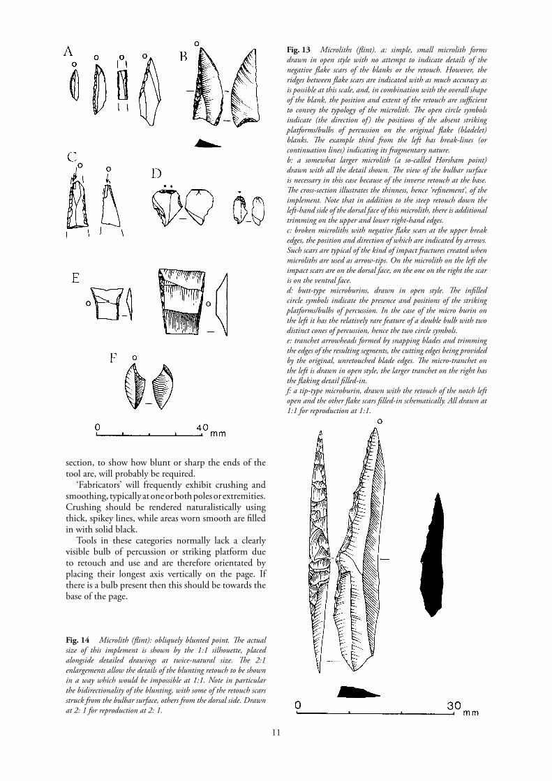
section, to show how blunt or sharp the ends of the tool are, will probably be required.
‘Fabricators’ will frequently exhibit crushing and smoothing, typically at one or both poles or extremities. Crushing should be rendered naturalistically using thick, spikey lines, while areas worn smooth are filled in with solid black.
Tools in these categories normally lack a clearly visible bulb of percussion or striking platform due to retouch and use and are therefore orientated by placing their longest axis vertically on the page. If there is a bulb present then this should be towards the base of the page.
Fig. 13 Microliths (flint). a: simple, small microlith forms drawn in open style with no attempt to indicate details of the negative flake scars of the blanks or the retouch. However, the ridges between flake scars are indicated with as much accuracy as is possible at this scale, and, in combination with the overall shape of the blank, the position and extent of the retouch are sufficient to convey the typology of the microlith. The open circle symbols indicate (the direction of ) the positions of the absent striking platforms/bulbs of percussion on the original flake (bladelet) blanks. The example third from the left has break-lines (or continuation lines) indicating its fragmentary nature. b: a somewhat larger microlith (a so-called Horsham point) drawn with all the detail shown. The view of the bulbar surface is necessary in this case because of the inverse retouch at the base. The cross-section illustrates the thinness, hence ‘refinement’, of the implement. Note that in addition to the steep retouch down the left-hand side of the dorsal face of this microlith, there is additional trimming on the upper and lower right-hand edges. c: broken microliths with negative flake scars at the upper break edges, the position and direction of which are indicated by arrows. Such scars are typical of the kind of impact fractures created when microliths are used as arrow-tips. On the microlith on the left the impact scars are on the dorsal face, on the one on the right the scar is on the ventral face. d: butt-type microburins, drawn in open style. The infilled circle symbols indicate the presence and positions of the striking platforms/bulbs of percussion. In the case of the micro burin on the left it has the relatively rare feature of a double bulb with two distinct cones of percussion, hence the two circle symbols. e: tranchet arrowheads formed by snapping blades and trimming the edges of the resulting segments, the cutting edges being provided by the original, unretouched blade edges. The micro-tranchet on the left is drawn in open style, the larger tranchet on the right has the flaking detail filled-in. f: a tip-type microburin, drawn with the retouch of the notch left open and the other flake scars filled-in schematically. All drawn at 1:1 for reproduction at 1:1.
Fig. 14 Microlith (flint): obliquely blunted point. The actual size of this implement is shown by the 1:1 silhouette, placed alongside detailed drawings at twice-natural size. The 2:1 enlargements allow the details of the blunting retouch to be shown in a way which would be impossible at 1:1. Note in particular the bidirectionality of the blunting, with some of the retouch scars struck from the bulbar surface, others from the dorsal side. Drawn at 2: 1 for reproduction at 2: 1.

12
6. Cores (Fig. 1, no. 13 and Figs. 16-18) If a core is to be drawn, then its illustration should
show clearly to the viewer how it has been flaked to its present state from the platform or platforms which it retains. In the case of a single-platform core, it is usually sufficient to select for detailed illustration a frontal view which shows most of the surface flaked from that platform, with the platform edge to the top of the page and approximately parallel to it (Fig. 16). This view may need to be accompanied by a cross-section or side profile to clarify the shape of the core, and it may be appropriate to show a view or outline of the platform surface. If the core has two or more platforms, then as many views as necessary to show the existence of all the platforms will be needed (Figs. 17-18). These views should normally represent a different aspect of the core as it is turned on its axis while keeping the same orientation, and if so the views can be mounted alongside each other across the page. If the orientation has to be changed then the views will need to be positioned in such a way as to reflect this, with linking lines as appropriate. I Cores often retain sizeable areas of cortex and if large numbers are to be drawn it may, in consultation with the specialist, be possible to represent the cortex by a convention – such as an even ‘Letratone’ or rub-on stipple – rather than attempting naturalistic depiction of the cortex in each case.
Drawings of cores can be very informative about the technology of the assemblage being studied, but cores can also be extremely time-consuming to illustrate in large numbers, especially if a fully representational style is used (see for example drawings by J. Richards in Saville 1981b,
Fig. 15, a & b ‘Fabricator’ (flint). Extensively worked implement with a markedly triangular cross-section. The ventral aspect on the right lacks any trace of the original bulbar surface, so there is no ‘right’ or ‘wrong’ way to orientate this piece, other than setting it with the long axis parallel to the page axis. This ‘fabricator’ has abraded areas at each pole, both worn completely smooth and therefore shown on the drawing by black infill. Drawn at 1:1 for reproduction at 2:3; shown in unreduced (a) and reduced (b) versions.
Fig. 16 Pyramidal single-platform core (flint). This core is of a specialized but common type with bladelets struck from all around the edge of a single platform. One view of the core face to show the overall size and the nature of the flake scars is all that is required, together with a view of the platform surface. Drawn at 1:1 for reproduction at 1 :1.

13
figs. 50–52). Some workers have adopted a more schematic, impressionistic approach to their core illustrations (for example Case and Whittle 1982, fig. 39), which is perhaps more appropriate for drawings which are to be put in an archive or inventory rather than a primary publication.
Fig. 18 Palaeolithic discoidal core (andesite). The character of the coarse stone is suggested by the use of jagged lines on the flake scar surfaces. This artefact is also partly ‘rolled’, and the worn flake ridges are shown in a negative fashion by the open areas between the scars. Drawn at 1:1 for reproduction at 2:3.
Fig. 17 Multiplatform core (flint) which has had several phases of flaking from different platforms. The illustration of the three views is necessary to convey adequately the overall shape of the core and to reveal all the main flake scars. Drawn at 1:1 for reproduction at 2:3.

14
7. Arrowheads and other pressure-flaked pieces (Figs. 19-20 and 25)Leaf-shaped arrowheads (Fig. 19, top), barbed and-tanged arrowheads (Fig. 19, bottom and 25) piano-convex knives, and some other types of implement (Fig. 20) may have complex pattern of tiny negative flake scars resulting from pressur flaking at the secondary retouch stage. If fairly flat, then an overall uniformity of tone in the shading of the flake scars, drawn with a delicate line, will best convey the skill of the knapper in producing such intricate pieces.
Unless the two surfaces of individual leaf-shaped and barbed-and-tanged arrowheads are markedly different, for example if one face has only marginal trimming, it is not necessary to illustrate both sides. In the case of chisel (Fig. 19, middle) and oblique arrowhead types, however, both the dorsal and ventral surfaces require depiction. The surface view of an arrowhead should always be accompanied by a vertical profile or longitudinal cross-section, whereas a transverse cross-section (or sections) is often more informative with such implements as piano-convex knives. In other words, the cross-section shown should be the one most relevant to the particular implement type being drawn, not chosen according to an arbitrary formula. (In a recent catalogue with many otherwise excellent drawings of flint artefacts, all the cross-sections were horizontal ones, irrespective of whether the implements were leaf-shaped arrowheads, end scrapers, or piercers: Kinnes and Longworth 1985.)
Pointed arrowheads should be orientated with the point towards the top of the page, chisel arrowheads with the broadest unretouched, or least retouched, edge to the top.
8. Scrapers (Fig. 1, nos. 8-9 and Fig. 21)The dorsal view and a longitudinal section or side profile are normally sufficient. If a prepared base is present, or there is any other deliberate modification of the bulbar surface, then the ventral view should also be drawn. A markedly steep or overhung retouched edge may necessitate the drawing of a full side view or a partial side view of the obscured part (Fig. 21, lower).
The normal convention now is for end scrapers to be illustrated with the scraping edge to the top of the page, though the opposite orientation has been adopted by some authorities in the past (in England notably J.G.D. Clark; see for example the famous Star Carr report: Clark 1954, fig. 40).
Fig. 19 Neolithic and bronze age arrowheads (flint). Top: leaf-shaped arrowhead; middle: transverse (chisel) arrowhead; bottom: two barbed-and-tanged arrowheads. It is not always essential for a specialist report to show the two views of the leaf-shaped arrowhead as drawn here; a single view could suffice as it does for the barbed-and-tanged arrowheads. On the other hand the ventral view does provide further information, particularly by showing the small surviving area of the original bulbar surface. Elaborate drawings of ‘perfect’ specimens like this leaf-shaped arrowhead are also, of course, useful in more popular publications and publicity material (and in illustrators’ portfolios!). Two views are always necessary to ensure typological clarity in the case of the transverse arrowheads, however, since the form and extent of flaking are less predictable than for other arrowhead types. Note in particular with the arrowheads that in each drawing the edges of the retouch flake scars are clearly defined, and that the sequence of flaking of each scar with regard to its neighbour can be ‘read’. An inexperienced illustrator or one who does not understand the principles of knapping will invariably ‘fudge’ the flake scar pattern when presented with an arrowhead to draw, thus creating an impressionistic and fundamentally flawed illustra- tion. Drawn at 1: 1 for reproduction at 1: 1.

15
9. Piercers (Fig. 1, no. 11 and Fig. 22)These tools, which may also be variously termed awls and borers, are distinguished by the presence of one or more pointed terminals. The enormous variety of piercer forms precludes hard-and-fast conventions, other than that the normal orienta- tion is with the point (or the most pronounced point if there are more than one) towards the top of the page and the bulbar end (if the piercer is on a flake blank) towards the base of the page. The illustration of a piercer should also show clearly the three-dimensional shape of the pointed element, using if necessary a combination of partial views, profiles, and cross-sections.
10. Unusual or irregular forms (Figs. 21 and 23) It is frequently necessary to illustrate miscellaneous implements which may be extensively worked, but which are not, typologically speaking, closely classifiable, and for which precise (and previously illustrated) parallels may be unavailable. In these cases the important thing is to follow the normal conventions, such as positioning the piece with its striking platform/bulbar end towards the base of the page, and then to ensure that the particular attributes of the implement are shown. Thus in the case of the irregular, denticulate scraper-type tool (in Fig. 21, lower), the steep, overhung retouched edges are fully depicted. With the chisel-like implement in Fig. 23, the tranchet-blow retouch from the right at the distal end on the dorsal surface and the distal thinning by removals across the ventral face are both carefully shown.
11. Hammerstones (Fig. 24)The most characteristic features of a hammerstone are the one or more areas of crushing which occur on the surface as the result of repeated percussive impact during use. This crushing is depicted by the use of short, jagged irregular lines (Fig. 24, edge view). On flint hammerstones the crushed area may contain pronounced faceting with relatively deep areas which appear in shadow and require the use of very close-set lines or spots of solid black in the drawing. The implement shown in Fig. 24 has also been used as an anvil or resting-block for the working of other objects, a use which has left traces on the surface of the stone in the form of parallel indentations and other abrasion marks.
Layout and reduction
It may be found easier and more convenient to draw each artefact (sometimes each view of the same artefact) on a separate piece of paper or film and then to mount these up into a page illustration using small pieces of transparent ‘magic’ tape (preferable to adhesives such as ‘Cow gum’ because it is less messy and incurs less danger of the individual drawings slipping). This kind of paste-up is best done on to board, rather than limp paper, card, or film, to avoid the danger of the drawing being rolled up and the separate drawings becoming wrinkled or otherwise distorted. If it is necessary to reposition any of the separate drawings at a subsequent stage, the transparent tape should be cut with a scalpel blade and the redundant pieces of tape left in place rather than peeled off with the consequent risk of spoiling the background surface. The illustrator should avoid mounting more than one thickness of paper in the paste-up; thus a scale drawn on a separate piece of paper should not be positioned on top of another piece of paper with an artefact drawing, nor should mounted drawings be combined with drawings already on the background. The reason for this is that problems of focusing can arise from even slight variations in the depth of the page of mounted drawings, leading to loss of detail in the reproduction.
An alternative method of presenting the individual drawings as a page layout is to trace the final pen drawings directly from the pencil originals on to a single sheet of drawing-film marked up (in a ‘drop-out’ blue) to the required size for reduction to the image area of the intended publication.
Every effort must be made to obtain precise information on the page size and image area of the intended publication – the illustrator going directly to the author or editor if the specialist is unable to be specific. If the method of eventual publication is unknown, or the drawings are for archive, then an A4 page layout allowing a minimum 25mm border on all four sides is perhaps the best (i.e. an area 161 x 247mm at 1:1, which equals 241.5 x 370.5mm for 2:3 or 66.6% reduction and 322 x 494mm for ½,
Fig.20 Bronze age knife (flint). A large flake with secondary retouch along the whole perimeter apart from the platform, where the small dorsal removals predate the striking of the flake itself. Areas of damage in the middle of both lateral edges are shown by break lines, which clarify the status of the invasive scars on the bulbar face. Drawn at 1:1 for reproduction at 2:3.

16
Fig. 21, a & b Scrapers (flint). The upper two illustrations show common scraper types which are adequately represented by the dorsal views and longitudinal cross-sections. The lower illustration shows a more irregular and unusual denticulate-type scraper, which may also have functioned as a piercer. In the latter case additional partial edge views have been necessary to depict fully the steep and overhung retouch at the distal end. Drawn at 1:1 for reproduction at 1:1 or 2:3; shown in unreduced (a) and reduced (b) versions.
17
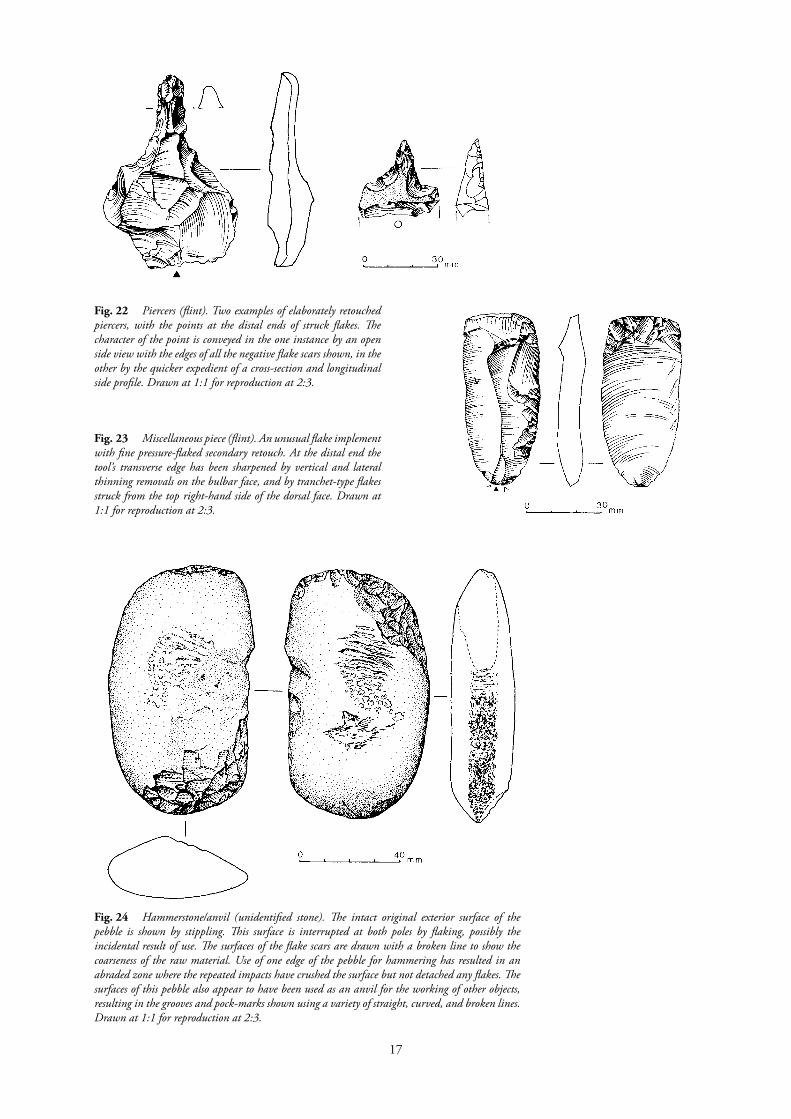
Fig. 22 Piercers (flint). Two examples of elaborately retouched piercers, with the points at the distal ends of struck flakes. The character of the point is conveyed in the one instance by an open side view with the edges of all the negative flake scars shown, in the other by the quicker expedient of a cross-section and longitudinal side profile. Drawn at 1:1 for reproduction at 2:3.
Fig. 23 Miscellaneous piece (flint). An unusual flake implement with fine pressure-flaked secondary retouch. At the distal end the tool’s transverse edge has been sharpened by vertical and lateral thinning removals on the bulbar face, and by tranchet-type flakes struck from the top right-hand side of the dorsal face. Drawn at 1:1 for reproduction at 2:3.
Fig. 24 Hammerstone/anvil (unidentified stone). The intact original exterior surface of the pebble is shown by stippling. This surface is interrupted at both poles by flaking, possibly the incidental result of use. The surfaces of the flake scars are drawn with a broken line to show the coarseness of the raw material. Use of one edge of the pebble for hammering has resulted in an abraded zone where the repeated impacts have crushed the surface but not detached any flakes. The surfaces of this pebble also appear to have been used as an anvil for the working of other objects, resulting in the grooves and pock-marks shown using a variety of straight, curved, and broken lines. Drawn at 1:1 for reproduction at 2:3.
18

19
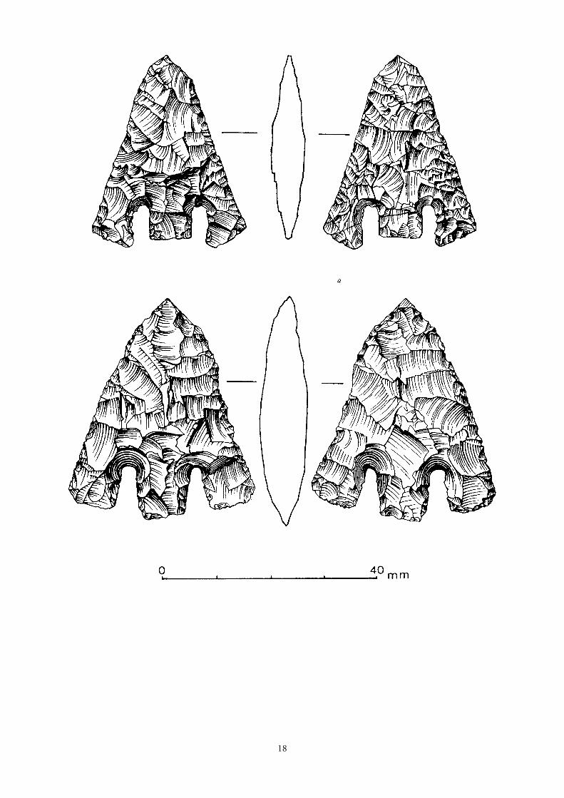
Fig. 25, a-d Examples of the effects of reduction. Two Bronze Age barbed-and-tanged arrowheads (flint), drawn at twice life-size for reproduction at actual size. Shown here reproduced at 2:1 (a), 1:1 (b), 2:3 (c) and 1:2 (d)

20
1:2, or 50% reduction) . The image area available in a staple-bound type of A4 publication (e.g. British Archaeological Reports) is even smaller, however, at about 150 x 230mm. The appropriate space required for a caption must always be allowed for within the image area of a page layout.
An image area of 161 x 247mm is also appropriate when preparing camera-ready copy for standard microfiche frames. Apart from the considerable inconvenience of using any drawings published on microfiche, however, lithic illustrations are not easily adaptable for fiche because of the very thin line widths employed when drawing lithic artefacts at 1:1. Any line thinner than 0.2mm is unlikely to reproduce on a print-out from fiche (see the guidelines in Bryant 1986). As a general rule every effort should be made to avoid having lithic drawings included on microfiche. If microfiche are unavoidable, then in many ways it is preferable that the text of a specialist lithic report, rather than the illustrations, should be on fiche.
Flint and stone implements are usually drawn at 1: 1 and are usually reduced to either 1/3rds linear (i.e. to 66.6% of their original size) for publication at 2:3, or are reduced to ½ linear (i.e. to 50% of their original size) for publication at 1 :2. Particularly detailed drawings of smaller implements like arrowheads are sometimes drawn and reproduced at actual size (1:1), and a scale of 3:4 has been used for a recent publication of palaeolithic artefacts (Green 1984). Exceptionally large artefacts (e.g. very large cores or stone axe-hammers) are reduced further to be published at 1:3 or even at 1:4.
The degree of reduction, however, will depend upon the size of the actual artefact or the average size of the artefacts to be illustrated from a particular assemblage, rather than upon any specific rules of reduction for particular types of implement. Thus, while publication at 2:3 or 1:2 will be the norm for most assemblages of later prehistoric flint implements from the chalk regions of southern and eastern England, where the average artefact size is usually quite large, it will not necessarily suit many assemblages from other areas of Britain where the raw materials dictated a small average size for the artefacts and for which 1: 1 reproduction is standard. The reduction factor should be uniform throughout an assemblage or an individual report, except where certain instances or classes of very small or very large artefacts are present in addition to those of average size. Thus a mesolithic assemblage may well be published with the scrapers, piercers, etc. at 2:3, but with microliths and microburins at 1:1. It is preferable for the reduction factors not to be mixed within a single illustration, but if this cannot be avoided a clear distinction should be apparent, such as a solid line separating those artefacts at different scales. Great care must be exercised in the mounting up of the original drawings if different reductions are required during the printing of single pages of illustrations, and explicit instructions given
to the editor/printer. In the case of all drawings for reduction, certain
rules always apply: for example, pen lines must be thick enough to stand reduction and must be spaced sufficiently well apart to avoid blocking up (Fig. 25). Separate scales (metric) must be included with every page of drawings or every separate illustration. A simple horizontal line with vertical subdivisions every l0mm (and even at every 1mm for the first l0mm), is by far the best. Elaborate scales which detract attention from the drawing should be avoided. Again, different scales should be added to the relevant parts of a page of drawings if there are different reduction factors involved.
The aesthetics of positioning separate drawings together on a page are difficult to stipulate dogmatically and the specialist may require the illustrations to be grouped in such a way as to offend all aesthetic principles. Generally, however, implements of the same type will be grouped together and some leeway is available to the illustrator in how the separate artefacts are positioned. The objective should be to achieve a balanced impression and to avoid, wherever possible, large areas of blank paper or ‘lines’ of blank space running in any direction other than horizontally. Absolute symmetry within a multi-object lithic illustration is impossible, but a relative symmetry, exploiting general size similarities, can be used to create a pleasing effect. Preliminary trial-and-error is essential, trying a variety of layouts until the most appropriate is achieved (bearing in mind the need to leave space for numbers and scales). All things being equal, a page which includes both large and small artefacts will look better if the small artefacts are towards the top of the page, the large ones at the bottom.
Conjoins and refits
Recent years have seen a growth in the study of reduction (i.e. knapping) sequences and intra-site distribution patterns by examining the evidence for conjoining and refitting artefacts and fragments from within an assemblage. The illustration of the results of this work can present a real challenge to the illustrator’s skill as the pieces involved can be extremely complex. For example, a core to which large numbers of flakes have been refitted may have gone through several stages of reduction from different platforms, and each stage and its flake products may need depiction in the illustration. One approach to this is to illustrate fully the final core stage (without any refitted flakes) and the initial stage (with all refitting flakes in place – see Fig. 26), and to accompany these by more schematic representations of the intermediary stages.
In drawings of this kind there is obvious scope for developing a range of symbols to assist the readability of the illustration. Thus in a core reduction sequence, for example, it is invaluable to mark the final, residual core with a symbol – such as an asterisk – throughout the

21
Fig.
26
Nod
ule
(flin
t) re
cons
truc
ted
by r
efitti
ng a
n al
mos
t co
mpl
ete
seque
nce
of s
truc
k fla
kes
and
core
s. Th
e co
rtex
of
the
nodu
le is
show
n by
stip
ple i
n th
e nor
mal
way
, but
‘Let
rato
ne’ (
shee
t LT
369)
is
also
used
to
indi
cate
tho
se ar
eas
whi
ch, a
lthou
gh n
ot
cort
ical,
wer
e ex
posed
to
natu
ral
dam
age
befo
re t
he n
odul
e w
as
acqu
ired
for h
uman
use.
The j
uncti
on of
the s
epar
ate fl
akes
is sh
own
by u
se of
a h
eavy
con
tinuo
us li
ne, a
nd e
ach
elem
ent i
s sep
arat
ely
enum
erat
ed b
y an
alph
abet
ical s
eque
nce w
hich
wou
ld b
e rela
ted
to
othe
r dra
win
gs o
f sta
ges o
f flak
ing
or se
para
te a
rtefa
cts, a
nd to
the
text
desc
riptio
n. Th
e aste
risk
and
blac
k do
t are
sym
bols
indi
catin
g tw
o po
sitio
ns o
n th
e ext
erio
r of t
he re
sidua
l cor
e, an
d w
hich
wou
ld
be sh
own
separ
ately
in a
n ac
com
pany
ing
draw
ing.
Dra
wn
at 1
:1
for r
epro
ducti
on a
t 2:3
.

22
matching sequence of drawings, to provide the reader with a visual key. Where a flake which has subsequently been retouched into an implement can be refitted to a core, it may be necessary to use an ‘exploded’ view to show exactly how it is located, without being masked by other refitting flakes. Individual flakes or implements which have been reconstructed from separate fragments are drawn in the normal way, but with heavy solid lines across the pieces at the appropriate positions to show the hidden breaks.
Although the conjoining of lithic artefacts was practised (and illustrated) by some early antiquaries in Britain (for example Smith 1894), and although isolated refitted pieces have continued to be illustrated (see, for example, a reconstructed neolithic axe head drawn by J. Richards in Saville 1981b, fig. 61), it is in France and particularly Belgium that some of the most spectacular illustrations of refitting flake sequences have been published in recent years. The illustrations by Yvette Baele of the reconstructed cores from the upper palaeolithic site at Meer in Belgium (Van Noten 1978) must rank as some of the finest lithic illustrations in the archaeological literature. In France the most famous site for refitted flints is Pincevent, again of upper palaeo lithic date. The illustrator for the Pincevent project, R. Humbert, uses a much heavier, bolder style of lithic drawing than Baele; examples of the two styles can be seen in Cahen et al. 1980.
Symbols and special effects
It is becoming increasingly common to add symbols to lithic illustrations to clarify points of technology and to give additional information about use and wear. Such details are often not readily apparent from the drawing itself because the traces are very slight or even microscopic.
When symbols are used (other than very obvious and basic ones), it is important that they be explained in the accompanying text so that their intention is clear. (For a lithic report where fairly extensive use of symbols has been made in the illustrations of neolithic flints see Saville 1981b.) Some of the conventional symbols in common use are shown below (Fig. 27). Modern damage to a prehistoric artefact is frequently indicated simply by leaving the relevant areas blank, but in some cases an appropriate symbol may be necessary to make the meaning clear.
Some conventions are so well-established in their use that no separate explanation is necessary. These include the use of near-parallel lines on the surface of polished axe heads (Fig. 10) and the use of solid black to indicate small areas of smoothing or polish (Figs. 15 and 28, upper).
In some cases it may be felt necessary to show in more detail the feature being highlighted by a symbol. One example of this would be the illustration of very fine retouch by adding an enlargement of the relevant area at twice the scale of the implement itself (Fig. 28,
lower). The possibility of publishing ‘open’ drawings of
lithic artefacts in some instances has already been mentioned. Such drawings, on which the ridges between flake scars are drawn accurately but the flake scars themselves are not filled in (Fig. 1), are most suitable in the case of easily ‘readable’, typologically consistent artefacts such as scrapers (Fig. 29). Outline drawings with little or no internal detail are frequently used to illustrate catalogue-type publications of axeheads and similar implements, especially unperforated neolithic polished stone axeheads (e.g. Adkins and Jackson 1978), but these are much enhanced by the use of stipple on the planform view (e.g. Field and Woolley 1984).
Colour has in the past been used to illustrate the differential surface discolouration of flints (e.g. watercolour drawings in Smith 1926, plate II), but in the rare cases when this is now deemed necessary the same effect can be achieved more efficiently by reproducing colour photographs (e.g. Wymer 1968, frontispiece). Full-colour reproduction of lithic implements is a luxury more appropriate to popular publications with large print-runs, and will rarely be an option for illustrating specialist reports. Nevertheless, the advantages of colour photographs of lithic material can be appreciated in Clarke et al. 1985.
Fig. 27 Some symbols used as conventions on lithic illustrations
23
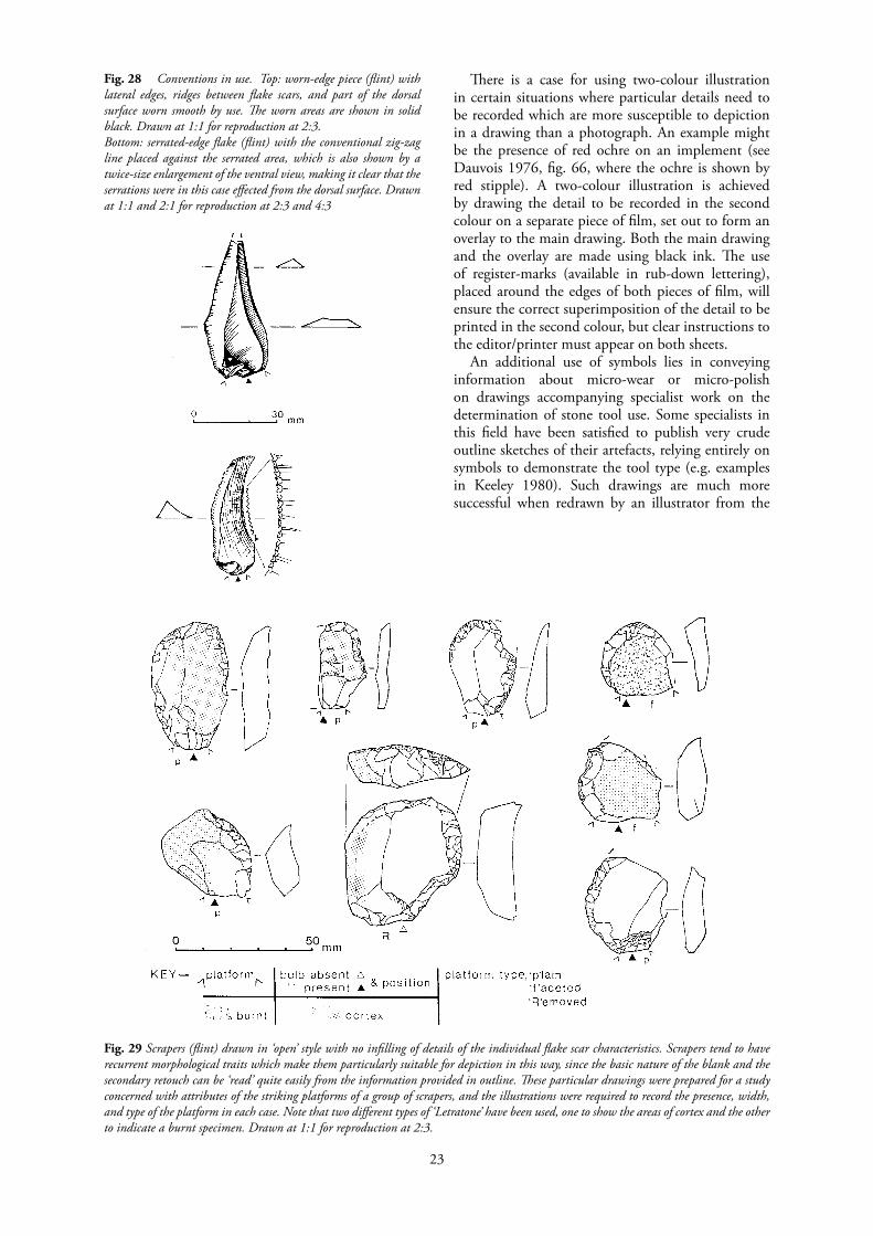
There is a case for using two-colour illustration in certain situations where particular details need to be recorded which are more susceptible to depiction in a drawing than a photograph. An example might be the presence of red ochre on an implement (see Dauvois 1976, fig. 66, where the ochre is shown by red stipple). A two-colour illustration is achieved by drawing the detail to be recorded in the second colour on a separate piece of film, set out to form an overlay to the main drawing. Both the main drawing and the overlay are made using black ink. The use of register-marks (available in rub-down lettering), placed around the edges of both pieces of film, will ensure the correct superimposition of the detail to be printed in the second colour, but clear instructions to the editor/printer must appear on both sheets.
An additional use of symbols lies in conveying information about micro-wear or micro-polish on drawings accompanying specialist work on the determination of stone tool use. Some specialists in this field have been satisfied to publish very crude outline sketches of their artefacts, relying entirely on symbols to demonstrate the tool type (e.g. examples in Keeley 1980). Such drawings are much more successful when redrawn by an illustrator from the
Fig. 29 Scrapers (flint) drawn in ‘open’ style with no infilling of details of the individual flake scar characteristics. Scrapers tend to have recurrent morphological traits which make them particularly suitable for depiction in this way, since the basic nature of the blank and the secondary retouch can be ‘read’ quite easily from the information provided in outline. These particular drawings were prepared for a study concerned with attributes of the striking platforms of a group of scrapers, and the illustrations were required to record the presence, width, and type of the platform in each case. Note that two different types of ‘Letratone’ have been used, one to show the areas of cortex and the other to indicate a burnt specimen. Drawn at 1:1 for reproduction at 2:3.
Fig. 28 Conventions in use. Top: worn-edge piece (flint) with lateral edges, ridges between flake scars, and part of the dorsal surface worn smooth by use. The worn areas are shown in solid black. Drawn at 1:1 for reproduction at 2:3.Bottom: serrated-edge flake (flint) with the conventional zig-zag line placed against the serrated area, which is also shown by a twice-size enlargement of the ventral view, making it clear that the serrations were in this case effected from the dorsal surface. Drawn at 1:1 and 2:1 for reproduction at 2:3 and 4:3

24
specialist’s original sketches, even if the artefact is only shown in outline, and it is certain that some academic journals and publishers would insist upon this rather than accept crude sketches. (See Green et al. 1982, figs. 1 and 4-6 for very effective drawings by Paul Hughes of flint daggers .tlsing separate outline illustrations to show microwear, fibre traces, and polish. )
Stones other than flint
Different types of stone will exhibit different appearances, both naturally and when worked, and the illustrator must seek to reproduce these differences. A combination of naturalistic rep- resentation and the use of various stylized conventions is required. With coarse stone such as andesite, diorite, and quartzite, for example, a broken, modulated line for the flaked surfaces will be most suitable (Figs. 9, 18, and 30). It is especially subjective as to where the line should be broken and as to the arrangement and direction of the lines, but the following points can be made:
1. Often the ridges that separate the flake scars are poorly defined. Where this is the case, the drawing should lack the solid line defining the edge of the flake removal.
2. Coarse stone tends to look less reflective in terms of highlight, due to the irregular surface of the flake scars, so a more comprehensively textured effect is needed.
3. Where the original outer surface of a block of stone used for manufacturing an implement remains, it may sometimes be very smooth and shiny in comparison with the flaked areas. The drawing should convey this contrast.
4. Some stone tools are worked only very crudely, or else the raw material used is so coarse that the knapper’s skill is masked. In such cases ~he ‘wild’ appearance of the original must be retained in the drawing, but the illustrator should also inject some structure into its depiction. The skill here, in collaboration with the specialist, is to keep a balance between over- and under-interpretation in the drawing.
The surfaces of finer-grained rocks, and stones which have been worked by pecking and smooth ing or polishing, are usually jllustrated,by stippling (Figs. 31-32). Details can be shown by variations in the density of the stipple, while contrasting rough and smooth areas can be emphasized by different sizes of stipple. Polished axeheads of very fine-grained stone sometimes have their polished surfaces depicted in the same way as those of flint axeheads (Fig. 10), that is using straight, near parallel lines following the long axis of the object.
When publishing large numbers of stone axeheads, hammerstones, maceheads, battle- axes, etc., often only outline views and cross-sections of the objects are shown, together with the details of such features as perforations and side facets. The outline drawings of these objects employ a number of specific
conventions, for example the way in which the form of a perforation is shown on a side view using a dotted line (see the illustrations in Roe 1979).
Further reading
As a general and inexpensive introduction to flintwork the British Museum’s guidebook Flint implements: an account of stone age techniques and cultures (written by W. Watson and originally published in 1949, now available as a reprint of the 1968 3rd edn) is well worth obtaining. It also contains a mixture of artefact illustrations, mostly excellent, a few less successful, and”often lacking what would now be seen as th~ appropriate -sections, profiles, and conventions. It is. instructive to study the various illustrative styles and techniques used in the different drawings in this and other books and to attempt to rationalize why some examples can be said to work better than others.
Equally valuable as an introduction is the rival guidebook Man the toolmaker (1st edn 1949, 6th edn 1972) from the British Museum (Natural History), written by K. P. Oakley. This book contains some superb drawings by C. O. Waterhouse, an illustrator working for the British Museum in the 1920s–1940s who showed a particular aptitude for lithic illustration. Waterhouse is generally acknowledged to have been one of the most outstanding of the British lithic illustrators and his work can be seen to advantage in the two, now rather rare, volumes published by the British Museum, which catalogue the Sturge Collection of artefacts (Smith 1931 and 1937). Another excellent illustrator working at the same period was Robert Gurd, perhaps better known for his brilliant illustrations of prehistoric pottery. A good selection of Gurd’s lithic work can be seen in Methuen’s County Archaeology volume for Sussex (Curwen 1937).
Also inexpensive and useful are the two Shire books on lithics (Pitts 1980; Timms 1974). Peter Timms’s book has an interesting series of simple but very successful illustrations by Romayne Timms in an open (somewhat Francophile!) style. Another valuable general introduction, by Bordaz (1970 and 1971; now out of print, but in many public libraries) is interesting for its use of black-and-white photographs (by L. Boltin) of numerous artefacts and for its schematic, ‘open’ drawings of types of upper palaeo lithic blade tools (by M. Smit). The splendid drawings of the French illustrator Pierre Laurent can be appreciated in François Bordes’s popular book The Old Stone Age (1968; now out of print, but often in public libraries) or in his classic work on the French lower and middle palaeolithic typology (Bordes 1981, 4th edn). A more recent book that is widely available is John Wymer’s The Palaeolithic Age (1982), which features an extremely useful series of lithic illustrations involving artefacts of various raw materials, but all drawn by the author himself, so detailed cross-comparison is possible and informative.

25
Fig. 30, a and b Examples of non-flint flakes. The flake on the left has secondary retouch down the left edge, that on the right is an unretouched blade. Note the way in which the ridges between flake scars are indicated by dashed lines or only by the starting points of the ripple-lines, not by continous lines. This emphasizes the less distinct nature of the flake ridges usually found on raw materials other than flint. In the drawing process a temporary pencil line is used to define the flake scar edge before the ripples are added, then erased after the ripples are inked-in. Drawn at 1:1 for reproduction at 2:3; shown in unreduced (a) and reduced (b) versions.

26
Popular handbooks on the production and use of lithic artefacts available in this country are currently lagging far behind the standards being set by our continental neighbours, for example in France (Piel-Desruisseaux 1986) and the Netherlands (Beuker 1983). It is also the case that general archaeological textbooks and works on prehistory in Britain very often have poor, or very mixed quality, lithic illustrations, while the best examples tend to be hidden away in obscure specialist publications and journals. Even in the most distinguished journals, however, some unacceptably poor lithic illustrations are still being published, for example those accompanying a recent article in the Proceedings of the Prehistoric Society (Ohel 1986, figs. 6-13), where the unnamed illustrator appears to have used a blotchy felt-tip! Until recently the only manual dealing specifically with lithic illustration was the rather specialist work by Dauvois (1976). This book, fascinating though it is, and containing quite superb drawings, does have some drawbacks for British illustrators, in that it is in French and is difficult to obtain in this country, but it is also a very technical treatise and the text can only be recommended to those who are going to take an academic interest in lithic illustration. If the opportunity presents itself, however, the illustrations in Dauvois’s book are well worth examination.
Fig. 31, a & b Neolithic polished stone axehead (rock type unknown). Stipple is used here to show not only the polished surface of the axehead, but also the various depressions where the polish is interrupted by the deepest areas of previous negative flake scars and by the more recent chips in the blade edge. The lateral edges are quite sharply bevelled, so the edge visible on the side view is shown by a solid line. Drawn at 1:1 for reduction to 1:2; shown in unreduced (a) and reduced (b) versions.

27
Apart from the Dauvois book there is now the readily accessible manual by Lucille Addington entitled Lithic illustration: drawing flaked stone artifacts for publication (1986). This is in many respects an excellent book and worthy of careful study by all lithic illustrators. Addington has included numerous valuable tips acquired during her long career as an illustrator and drawing instructor. Nevertheless, it is an American publication and many of the author’s terms and techniques may seem as foreign as those in Dauvois. Moreover, while there are an admirable number of fine illustrations, the artefacts are mainly from the New World or the Near East and include many types which the illustrator working on British material is unlikely to encounter, while excluding many common British implement types. Addington’s explanation of the ‘selective grid’ approach, using a
network of horizontal and vertical pencilled guide-lines to assist the translation of detail from one view to another is very full and useful, but does ignore the possibilities of alternative approaches, for example using transparent drawing-film.
Another recent American publication on lithic illustration, which appeared around the same time as Addington’s and so is not mentioned in her book, is by Philip Chase (1985) in the Newsletter of Lithic Technology. Chase directs his article at professional illustrators who find themselves required to tackle lithic material without previous experience, and so covers some of the same ground as the present booklet, but without considering practical questions of illustration such as materials and techniques.
Acknowledgements
All the illustrations in this booklet are the work of Hazel Martingell with the exception of Figs. 17 and 26, by Joanna Richards, and Fig. 31 by Susan Banks. For permission to reproduce various of the illustrations the authors are grateful to David Bick, Stephen Green, Roger Jacobi, and Roger Mercer, and general acknowledgements are also due to Cheltenham Art Gallery and Museum, English Heritage, Essex County Council Planning Department, and the National Museum of Wales.
The authors wish to thank the following colleagues who have read and commented upon all or parts of this paper in earlier drafts, and whose comments have undoubtedly served to make the text more readable: Paul Callow, Stephen Green, Frances Healy, Elizabeth Healey, Reay Robertson-Mackay, Caroline Wickham- Jones, and John Wymer. Especial thanks are due to Stephen Green, Frances Healy, and Joanna Richards for reading and checking the final draft. This booklet was skilfully seen into print by Roy Friendship-Taylor. Errors and idiosyncracies remain the sole responsibility of the authors.
Fig.32 Perforated pebble hammer (quartzite). This kind of implement usually comprises, as here, a naturally-shaped pebble modified only by the fashioning of the perforation. The external surface of the pebble is shown by an uneven stipple, with the addition of some short, squiggly lines to show areas of abrasion or other surface irregularity. Stipple is also used to show the inside of the hourglass perforation, but with some of it grouped into curvilinear and concentric (or straight and parallel on the sectional view) alignments where the hole has been marked during manufacture or use. The sectional view combines a ‘real’ view of the inside of the perforation with hatched cross-sections through the solid stone. Drawn at 1:1 for reproduction at 2:3.

28
APPENDIX: Equipment and Materials for Lithic Illustration
Details of materials and brands used will depend obviously upon personal preference, financial resources, and the availability of supplies. The following list is intended only as an indication of the types of equipment required or desirable, and these are listed in no particular order.
A3-sized (or larger) drawing-board covered with graph-paper or gridded drawing-film.
Desk lamp or drawing-board lamp of cantilevered spring type, the head of which can be positioned as required. Minimum bulb strength required is 60w; some prefer a lamp which will accept l00w bulbs. Some illustrators recommend a clear bulb rather than a pearl one as providing a sharper light.
Transparent, clear, double-matt polyester drawing-film (or drafting-film) such as ‘Permatrace’ by Admel or ‘Ozatex’ by Ozalid, but there are several brands and very considerable differences in prices. Most archaeological drawing-offices use drawing- film of 50 microns/.002 inches thickness (commonly called ‘two-thou’) and this is adequate for lithic drawings; some illustrators prefer .003 inches (‘three-thou’) film and it is certainly more difficult accidentally to fold and mark the thicker film, but it is also more expensive. Top quality tracing-paper may be useful for some interim drawing tasks, but is too unstable and differentially absorbent to be used for final, inked publication drawings.
Acetate drawing film is used when maximum transparency is required. Some acetate films only accept etching inks; two of those which can be drawn on with the same pens and inks as used for polyester films are ‘Artcel’ (by Frisk) and ‘Original Drawfilm’ (by Film Sales). These films can be purchased in A4- or A3-sized pads.
A white cartridge paper such as ‘CS 10’ (Colyer & Southey Ltd) with a smooth, hard finish is the best pape! surface to draw on, but is expensive, and a wide range of alternative cartridge papers is available and ‘sworn-by’ by different illustrators. Some lithic illustrators use only paper for their drawings, others make initial drawings on paper and final versions on film; others use film throughout.
Drafting-tape (e.g. ‘Scotch 230’, 25 mm wide) for all temporary adhesive requirements, either for the drawing-paper/film or for flints. Beware cheap masking-tapes, which either do not stick at all or will mark the drawing. If any drafting-tape is left on flint for too long, acetone (nail-varnish remover) will be necessary to get the ‘sticky’ off, but be careful this does not remove the identity mark as well.
Transparent adhesive tape of the ‘magic tape’ type (like ‘Scotch 810’ or ‘Sellotape Invisible’), can be used in a variety of ways on final drawings, as it will not show in printing and can be drawn on. This tape comes in different widths, of which the narrowest (12 mm) is cheaper and usually sufficient. Keep the tape in a dust-free container or it will accumulate dirt at
the edges which may show, as lines on the drawing when reproduced.
‘Plasticine’ modelling clay or ‘Blu-tack’ or similar for positioning objects at the correct orientation for your view.
Set-squares for checking correct outline details of thick objects, and for constructing right-angled guidelines on your paper. For the former task self-standing versions (e.g. carpenters’ squares) are advantageous.
Dividers, and calipers and/or slide gauge, for measuring surface details and thicknesses of objects.
Pencils, H or harder for drawing (clutch-type in various thicknesses useful), HB or softer for any temporary marks.
Pens: technical, tubular type (‘Faber-Castell’, ‘Rotring’, ‘Staedtler’, etc.), nib sizes 0.1-0.5 mm; mapping-pen or other split-nib type pen (e.g. ‘Rotring ArtPen’) for variable thickness lines.
Ink: various types of permanent black, often designated by manufacturers for specific brands of pen. Some are more suitable for use on drawing-film or on cartridge paper.
Erasers: pencil and ink types, some kinds more suitable for drawing-film. The old-fashioned pencil-type erasers designed for typewriter use have the virtue that they can easily be sharpened to a point.
Brushes: 1l/2-inch paint brush or similar for sweeping eraser debris from drawing and board.
Rub-down lettering (‘Letraset’ etc.) for num- bering artefacts on the final publication drawing. Such lettering almost always looks better than stencilled letters or numerals. For numerals use a sans-serif typeface, and choose for economy one which is available in numerals-only sheets (e.g. Helvetica Light or Univers 55). It is often advisable to protect rub-down lettering from abrasion and scratches by ‘fixing’ it with a protective spray (e.g. ‘103 Letracote Matt’).
‘Letraset’ and other brands produce rub-down symbols appropriate for some of the conventions used in flint illustration (Fig. 27). Solid, straight lines are also available in rub-down form on sheets and tapes and can be used for scales and link-lines.
Surgical blades (‘Swann-Morton’ etc.) for tidying ink lines on final drawings on film.
Shape-tracer (‘Copydex’ type etc.) for copying sections and profiles on larger, substantial implements like polished axeheads. Take care not to mark the surface of the object when using metal shape-tracers.
Sheet of perspex -approx. 300 x 250 mm (glass is sometimes used, but beware of the potential hazards), for use when tracing surface details. Thickness can be as little as 2 mm, but experimen- tation will be needed to determine the thickness of perspex necessary to retain sufficient rigidity during use by individual illustrators.
Tracing-machine (‘Grant’ projector etc.) or visualiser -if your drawing office has one it will be

29
useful for scaling-up and for checking reductions, and may be used for tracing outlines. Smaller, slightly less expensive, Japanese visualisers are now becoming available in Britain (e.g. ‘Gakken Perscope GAT-112’). Some photocopy machines are now accurate enough and of sufficient reproduction quality to give exact reductions and enlargements, which can reliably be used in the drawing process. Put a scale graduated in millimetres on the original drawing before photocopying so that the required scale of the reproduction can be checked easily.
Magnifying glass or binocular microscope –essential for examining very small flints like geometric
microliths. Magnifiers on stands or illuminated-ring magnifiers are used by some illustrators.
Pencils or pens in ‘drop-out’ blue (which does not reproduce in printing) for drawing borders, alignment marks, writing reduction instructions, etc. (e.g. ‘Staedtler Non-Print’). Note that unless used very faintly, ‘drop-out’ blue will appear on photographic slides, microfiche, and ‘Copyproof (PMT) reductions of illustrations, so if these are likely to be required keep the writing well away from the object so that it is out of frame or can easily be masked.
See Addington (1986, 113-117) for another list of illustrators’ equipment needs.
Bibliography
Addington, L. R. 1986. Lithic illustration: drawing flaked stone artifacts for publication. Chicago and London: University of Chicago Press. Adkins, R. and Jackson, R. 1978. Neolithic stone and flint axes from the River Thames: an illustrated corpus. London:’ British Museum Occasional Paper No.1. Beuker, J. R. 1983. Vakmanschap in vuursteen. Assen: Provincial Museum van Drenthe publicatie nummer 8. Bordaz, J. 1970. Tools of the old and new stone age. New York: The Natural History Press.Bordaz, J. 1971. Tools of the old and new stone age. Newton Abbot: David & Charles. Bordes, F. 1968. The Old Stone Age. London: Weidenfeld and Nicolson. Bordes, F. 1981. Typologie du paleolithique ancien et moyen (4th edn). Paris: Editions du Centre National de la Recherche Scientifique. (1st edn Bordeaux 1961). Bryant, R. 1986. Drawing for microfiche publication. Gloucester: Association of Archaeological Illustrators and Surveyors, Technical Paper No.7. Cahen, D., Karlin, C., Keeley, L. H., and Van Noten, F. 1980. Methodes d’analyse technique, spatiale et fonctionnelle d’ensembles lithiques. ‘ Helinium 20, 209-259. Case, H. J. and Whittle, A. W. R. (eds). 1982. Settlement patterns in the Oxford region: excavations at the Abingdon causewayed enclosure and other sites. London: Council for British Archaeology (Research Report No. 44). ! Chase, P. G. 1985. Illustrating lithic artifacts: I information for scientific illustrators. Newsletter of Lithic Technology 14 (2), 57-70. Clark, J. G. D. 1954. Excavations at Star Carr, an early mesolithic site at Seamer, near Scarborough, Yorkshire. Cambridge: Cambridge University Press. Clarke, D. V., Cowie, T. G. and Foxon, A. 1985. Symbols of power at the time of Stonehenge. Edinburgh: HMSO. Curwen, E. 1939. Blunted axe-like implements. Proceedings of the Prehistoric Society 5, 196-201. ! Icurwen, E. C. 1937. The archaeology of Sussex. London: Methuen Dauvois, M. 1976. Precis de dessin dynamique et structural des industries lithiques prehistoriques. Perigueux: Pierre Fanlac. Evans, Sir J. 1897. The ancient stone implements, weapons and ornaments of Great Britain (2nd edn). London: Longmans, Green, and Co. Field, D. and Woolley, A. R. 1984. Neolithic and bronze age ground stone implements from Surrey: morphology, petrology and distribution. Surrey Archaeological Collections 75,85-109. Green, H. S. 1984. Pontnewydd cave, a lower palaeolithic hominid site in Wales: the first report. Cardiff: National Museum of Wales (Quaternary Studies Monograph No.1). Green, H. S., Houlder, C. H. and Keeley, L. H. 1982. A flint dagger from Ffair Rhos; Ceredigion, Dyfed, Wales. Proceedings of the Prehistoric Society 48, 492-501. Keeley, L. H. 1980. Experimental determination of stone tool uses: a micro-wear analysis. Chicago and London:.University of Chicago Press. Kinnes, I. A. and Longworth, I. H. 1985. Catalogue of the excavated prehistoric and Romano-British material in the Greenwell Collection. London: British Museum Publications. Martingell, H. 1980. Drawing flaked stone artefacts. Lithic Studies Society Newsletter 1,8-10.Martingell, H. 1981. Readable drawings – the order of flake removals. Lithics 2,10-12.

30
Martingell, H. 1982. Drawing worked stone: variations in line type for different raw materials. Lithics 3,22-24. Martingell, H. 1983. Considerations for the illustration of large lithic assemblages. Lithics 4, 42-45.Oakley, K. P. 1972. Man the tool-maker (6thedn). London: The British Museum (Natural History). Ohel, M. Y. 1986. Milking the stones, or an Acheulian aggregation locality on the Yiron plateau in Upper Galilee. Proceedings of the Prehistoric Society 52, 247-280. Piel-Desruisseaux, J .-L. 1986. Outils prehistoriques: forme - fabrication - utilisation. Paris: Masson. Pitts, M. W. 1980. Later stone implements. Princes Risborough: Shire Publications. Roe, F. E. S., 1968, Stone maceheads and the latest Neolithic cultures of the British Isles. In J. M. Coles and D. D. A. Simpson (eds), Studies in ancient Europe, 145-172. Leicester: Leicester University Press. Roe, F. E. S. 1979. Typology of stone implements with shaftholes. In T. H. McK. Clough and W. A. Cummins (eds), Stone axe studies: archaeological, petrological, experimental and ethnographic. Lon- don: Council for British Archaeology (Research Report No. 23). R-oe, F. E. S. 1985. Two prehistoric implements found near Tytherington, Avon. Transactions of the Bristol and Gloucestershire Archaeological Society 103,220-222. Saville, A. 1981a. Grimes Graves, Norfolk, excavations 1971-72: vol. II, the flint assemblage. London: HMSO (Department of the Environment Archaeological Report No. 11). Saville, A. 1981b. The flint and chert artefacts. In R. J. Mercer, Excavations at Carn Brea, Illogan, Cornwall, 1970-73 - a neolithic fortified complex of the third millennium BC. Cornish Archaeology 20, 101-152. Smith, R. A. 1926. A guide to antiquities of the stone age (3rd edn). London: The British Museum.Smith, R. A. 1931. The Sturge collection: an illustrated selection of flints from Britain bequeathed in 1919 by William Allen Sturge. London: The British Museum. Smith, R. A. 1937. The Sturge collection: an illustrated selection of foreign stone implements bequeathed in 1919 by William Allen Sturge. London: The British Museum. Smith, W. G. 1894. Man the primeval savage: his haunts and relics from the hill-tops of Bedfordshire to Blackwall. London: Edward Stanford. Timms, P. 1974. Flint implements of the Old Stone Age. Princes Risborough: Shire Publications. Van Noten, F. 1978. Les chasseurs de Meer. Brugge: De Tempel (Dissertationes Ar- chaeologicae Gandenses Vol. 18). Wainwright, G.l. 1979. Mount Pleasant, Dorset: excavations 1970-1971. London: Society of Antiquaries of London (Report of the Research Committee No. 37). Watson, W. 1968. Flint implements: an account of stone age techniques and cultures (3rd edn). London: The British Museum. Wymer, J. 1968. Lower Palaeolithic archaeology in Britain as represented by the Thames Valley. London: John Baker. Wymer, J. 1982. The Palaeolithic Age. London: Croom Helm.