Embed Size (px)
Citation preview

1

2
3
Contents 1. Introduction .................................................................................................................................................... 6 2. Startup ............................................................................................................................................................ 6 3. Quick Start ...................................................................................................................................................... 8 4. Home ............................................................................................................................................................ 11 5. Execute ......................................................................................................................................................... 12 5.1 Graphical Display .......................................................................................................................................... 13 6. Menu ............................................................................................................................................................ 14
6.1 Developer Information ............................................................................................................................. 15
6.2 Diagnostics ................................................................................................................................................ 15
6.3 Event Logs ................................................................................................................................................. 16
6.3.1 General Event Log ............................................................................................................................. 17
6.3.2 Error Log ........................................................................................................................................... 18
6.3.3 Firing Log .......................................................................................................................................... 18
6.3.4 Schedule Log ..................................................................................................................................... 19
6.4 Schedules .................................................................................................................................................. 20
6.4.1 Schedule Summary ........................................................................................................................... 21
6.4.2 New Schedule ................................................................................................................................... 23
6.4.3 Edit Schedule .................................................................................................................................... 29
6.4.4 Delete Schedule ................................................................................................................................ 29
6.4.5 Favorites ........................................................................................................................................... 29
6.5 Settings ..................................................................................................................................................... 29
6.5.1 Auxiliary Output ................................................................................................................................ 30
6.5.2 Cost ................................................................................................................................................... 31
6.5.3 Date and Time .................................................................................................................................. 33
6.5.4 Display Mode .................................................................................................................................... 33
6.5.5 Fire Mode ......................................................................................................................................... 34
6.5.6 Network ............................................................................................................................................ 35
6.5.7 Notifications ..................................................................................................................................... 37
6.5.8 Preventative Maintenance ............................................................................................................... 38
6.5.9 Thermocouple Offset ........................................................................................................................ 40
6.5.10 Touchscreen Calibration ................................................................................................................... 40
6.6 SW Update ................................................................................................................................................ 41
7. Alarm Conditions .......................................................................................................................................... 42 8. Warranty ....................................................................................................................................................... 43
4
Table of Figures Figure 1 - Preliminary Boot Screen .............................................................................................................................7 Figure 2 - Date/Time Entry .........................................................................................................................................8 Figure 3 - Home Screen ..............................................................................................................................................8 Figure 4 - Schedule Selector .......................................................................................................................................9 Figure 5 - Execution Status ...................................................................................................................................... 10 Figure 6 - Edit Schedule ........................................................................................................................................... 10 Figure 7 - Graphical View ......................................................................................................................................... 11 Figure 8 - Graphical Display Data ............................................................................................................................ 13 Figure 9 - Graphical Display Zoom ........................................................................................................................... 14 Figure 10 - Main Menu ............................................................................................................................................ 15 Figure 11 - Diagnostics............................................................................................................................................. 16 Figure 12 - Event Logs .............................................................................................................................................. 17 Figure 13 - General Log ............................................................................................................................................ 17 Figure 14 - Error Log ................................................................................................................................................ 18 Figure 15 - Firing Logs .............................................................................................................................................. 19 Figure 16 - Schedule Log .......................................................................................................................................... 20 Figure 17 – Schedules .............................................................................................................................................. 20 Figure 18 - Schedule Selector .................................................................................................................................. 21 Figure 19 - Schedule Summary with Alerts ............................................................................................................. 22 Figure 20 - Schedule Summary with Aux 1 .............................................................................................................. 22 Figure 21 - Schedule Summary with Aux 2 .............................................................................................................. 23 Figure 22 - New Schedule ........................................................................................................................................ 24 Figure 23 - New Schedule with Alerts and Aux 1 .................................................................................................... 24 Figure 24 - New Schedule with Aux 1 and Aux 2 ..................................................................................................... 25 Figure 25 - New Schedule with Aux 2 ...................................................................................................................... 25 Figure 26 - Ramp Rate Entry (°F) ............................................................................................................................. 27 Figure 27 - Setpoint Entry (°F) ................................................................................................................................. 28 Figure 28 - Hold Time Entry ..................................................................................................................................... 28 Figure 29 - Settings .................................................................................................................................................. 30 Figure 30 - Auxiliary Outputs Settings ..................................................................................................................... 31 Figure 31 - Cost per KWh Entry ............................................................................................................................... 32 Figure 32 - Kiln Power Entry .................................................................................................................................... 33 Figure 33 - Display Settings ..................................................................................................................................... 34 Figure 34- Network Status ....................................................................................................................................... 35 Figure 35- Wireless Network Tab ............................................................................................................................ 36 Figure 36- Wired Network Tab ................................................................................................................................ 37 Figure 37 - Notifications .......................................................................................................................................... 37 Figure 38 - Preventative Maintenance .................................................................................................................... 38 Figure 39 - Relay Life Entry ...................................................................................................................................... 39

5
Figure 40 - Element Life Entry ................................................................................................................................. 39 Figure 41 - Thermocouple Life Entry ....................................................................................................................... 40 Figure 42 - Software Update ................................................................................................................................... 41

6
1. Introduction
WARNING: The TAP controller is not a safety device. The controller provides 12VDC outputs to operate relays, which in turn enable/disable kiln heating elements. It is possible for relays to fail in the on position. This controller cannot protect against relay failure.
NEVER LEAVE THE KILN UNATTENDED
The Temperature Automation by Proportional Integral-Derivative (TAP) controller is the first viable, commercially available temperature control solution which incorporates a Graphical User Interface (GUI) for end to end control of a Glass, Ceramic, Metal Clay, or Heat Treat firing process. This controller is designed to take the guess work out of firing schedule creation, modification, execution, and monitoring. The intuitive touchscreen interface utilizes a smart-phone like UI to enable immediate out of the box use. This unique design approach alleviates the need to continually refer back to this User Manual for performing the most basic tasks.
Your new controller is a full-featured device which, beyond extraordinary kiln control and temperature following characteristics, incorporates functionality to ensure peak performance for the life of your kiln and controller.
Features such as Diagnostics and Preventative Maintenance Alerts keep you abreast to the status and remaining life expectancy of critical kiln components, namely relays, thermocouples, and heating elements, based on the user defined settings that you employ.
Software Updates, available from your kiln manufacturers website, or for controllers purchase from SDS Industries directly, www.kilncontrol.com, ensure that you always have an up-to-date device. Software updates are deployed as new features are requested from users, enhancements to existing features are recommended, or any bugs are discovered that require a fix. The updates can be installed via USB thumb drive, or, if web enabled, via an automatic download from the SDS Industries server. Automatic downloads occur when the controller recognizes a new version is available from the server.
2. Startup
You’ve got TAP and it’s been installed, GREAT! Now let’s get started quickly.
When you apply power to TAP, the controller will go through a sequence of boot-up routines. Additionally, if you are able to see inside the control box, you’ll probably see a flashing blue LED and a solid red LED. These lights are normal and expected.
7
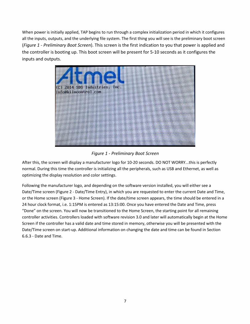
When power is initially applied, TAP begins to run through a complex initialization period in which it configures all the inputs, outputs, and the underlying file system. The first thing you will see is the preliminary boot screen (Figure 1 - Preliminary Boot Screen). This screen is the first indication to you that power is applied and the controller is booting up. This boot screen will be present for 5-10 seconds as it configures the inputs and outputs.
Figure 1 - Preliminary Boot Screen
After this, the screen will display a manufacturer logo for 10-20 seconds. DO NOT WORRY...this is perfectly normal. During this time the controller is initializing all the peripherals, such as USB and Ethernet, as well as optimizing the display resolution and color settings.
Following the manufacturer logo, and depending on the software version installed, you will either see a Date/Time screen (Figure 2 - Date/Time Entry), in which you are requested to enter the current Date and Time, or the Home screen (Figure 3 - Home Screen). If the date/time screen appears, the time should be entered in a 24 hour clock format, i.e. 1:15PM is entered as 13:15:00. Once you have entered the Date and Time, press “Done” on the screen. You will now be transitioned to the Home Screen, the starting point for all remaining controller activities. Controllers loaded with software revision 3.0 and later will automatically begin at the Home Screen if the controller has a valid date and time stored in memory, otherwise you will be presented with the Date/Time screen on start-up. Additional information on changing the date and time can be found in Section 6.6.3 - Date and Time.

8
Figure 2 - Date/Time Entry
3. Quick Start This section will guide you through the process to begin a kiln firing with a stored or custom schedule.
From the Home Screen (Figure 3 - Home Screen), press START. This will transition you to the schedule selector screen (Figure 4 - Schedule Selector).
Figure 3 - Home Screen

9
Figure 4 - Schedule Selector
Note: Figure 4 - Schedule Selector most likely will not match your display as it is largely dependent on the schedules you have loaded.
Note: You’ll know you’re at the home screen when System Status says “Standby,” and the breadcrumb says “Home.” This is also the first screen you'll see after setting the date and time.
From the schedule selector screen, select a pre-populated schedule, or create your own by pressing NEW SCHEDULE.
If you choose to enter your own schedule, please refer to Section 5.4.2 - New Schedule
After you have selected the schedule you wish to execute, press START. This will begin the firing process. During this stage of execution, you will be viewing the execution screen (Figure 5 - Execution Status) in which the following information will be available:
• Currently Executing Schedule Title (This is the title of the schedule you selected to run) • Current Executing Step of Total Steps (This indicates where in the overall schedule you currently are) • Current Board Temperature (This indicates the temperature internal to the control box) • Current Kiln Temperature (This indicates the temperature inside the kiln) • Current Step Ramp Rate (This indicates the degrees per hour (°F or °C) the kiln is programmed to ramp) • Current Step Setpoint (This indicates the temperature to which the kiln is heating/cooling) • Current Step Hold Time (This indicates the programed hold time for the step, or provides a countdown if
currently holding) • Current Firing Elapsed Time (This indicates the total time the firing has been running in HH:M:SS) • Current Firing Accrued Cost (This indicates the total accrued cost to the current point in the firing
(subject to appropriate settings))

10
Figure 5 - Execution Status
If, during the firing, you want to modify the currently executing schedule, press EDIT SCHEDULE. Once EDIT SCHEDULE is pressed, you will be transitioned to the EDIT SCHEDULE screen (
Figure 6 - Edit Schedule). This will give you the opportunity to modify any schedule steps beyond those that have already been executed. For more details on how to edit a schedule, refer to Section 5.4.3 – Edit Schedule.
Figure 6 - Edit Schedule
If, at any point during the firing, you want to advance the kiln schedule to the next step, simply press SKIP STEP. This can be performed at any point during a firing. When you press SKIP STEP, you will be presented with a
11
confirmation dialog. To complete the action and skip to the next step, you must press YES at the confirmation dialog.
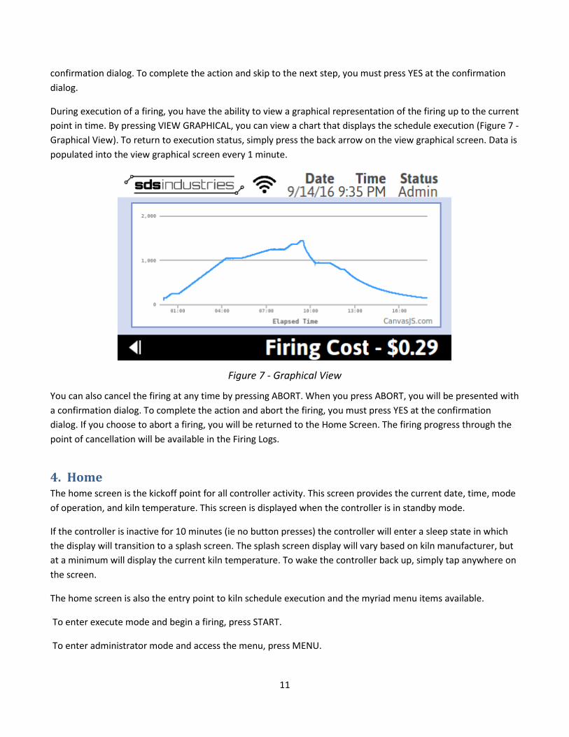
During execution of a firing, you have the ability to view a graphical representation of the firing up to the current point in time. By pressing VIEW GRAPHICAL, you can view a chart that displays the schedule execution (Figure 7 - Graphical View). To return to execution status, simply press the back arrow on the view graphical screen. Data is populated into the view graphical screen every 1 minute.
Figure 7 - Graphical View
You can also cancel the firing at any time by pressing ABORT. When you press ABORT, you will be presented with a confirmation dialog. To complete the action and abort the firing, you must press YES at the confirmation dialog. If you choose to abort a firing, you will be returned to the Home Screen. The firing progress through the point of cancellation will be available in the Firing Logs.
4. Home The home screen is the kickoff point for all controller activity. This screen provides the current date, time, mode of operation, and kiln temperature. This screen is displayed when the controller is in standby mode.
If the controller is inactive for 10 minutes (ie no button presses) the controller will enter a sleep state in which the display will transition to a splash screen. The splash screen display will vary based on kiln manufacturer, but at a minimum will display the current kiln temperature. To wake the controller back up, simply tap anywhere on the screen.
The home screen is also the entry point to kiln schedule execution and the myriad menu items available.
To enter execute mode and begin a firing, press START.
To enter administrator mode and access the menu, press MENU.
12
5. Execute The execution screen is the display which will be present for the duration of a firing. The screen provides all pertinent information with respect to the current firing as well as certain control features. The following is a list of information presented during a firing:
• Currently Executing Schedule Title (This is the title of the schedule you selected to run) • Current Executing Step of Total Steps (This indicates where in the overall schedule you currently are) • Current Board Temperature (This indicates the temperature internal to the control box) • Current Kiln Temperature (This indicates the temperature inside the kiln) • Current Step Ramp Rate (This indicates the degrees per hour (°F or °C) the kiln is programmed to ramp) • Current Step Setpoint (This indicates the temperature to which the kiln is heating/cooling) • Current Step Hold Time (This indicates the programed hold time for the step, or provides a countdown if
currently holding) • Current Firing Elapsed Time (This indicates the total time the firing has been running in HH:M:SS) • Current Firing Accrued Cost (This indicates the total accrued cost to the current point in the firing
(subject to appropriate settings))
The following is a list of control functions available during a firing:
• Skip Step (This function advances process control to the next user defined program step or completes the firing if no additional steps are programmed)
• Schedule Summary (This function provides the user an overall view of the current firing schedule programmed steps)
• View Graphical (This function provides a graphical representation of the firing up to the current point in time)
• Edit Schedule (This function allows the user to modify the current or future firing schedule steps) • Abort (This function cancels the firing, disabling all elements and reverting to Standby Mode)
Skip Step will transition the controller to the next step in the firing schedule. A confirmation dialog will be presented after Skip Step is pressed to ensure the selected operation is intended. If no additional steps are programmed, the controller will consider the firing complete and disable all elements.
Schedule Summary will bring up a new screen in which the currently executing firing can be viewed in a tabular format. No editing is allowed in this mode. The screen allows the user to review all parameters (Ramp Rates, Setpoints, Hold Times) associated with the current firing.
View Graphical will bring up a new screen in which the currently executing firing data points can be seen from the time the schedule started to the current time. Data points are populated every 1 minute. More information on the Graphical Display can be found in Section 4.1 - Graphical Display.
Edit Schedule will bring up a new screen, similar to Schedule Summary, however, the remaining schedule steps can be modified. Any unexecuted segment/step can be modified by pressing the corresponding table cell. Depending on the selected cell, you will either be prompted with an input instruction message and keypad

13
(Ramp Rate, Setpoint, Hold Time), or a Yes/No selection (Setpoint Alert, Hold Time Alert, Aux 1, Aux 2). The keypad will populate the previously programmed value when it displays. It is important to clear the existing value prior to entering the new value, if a change is preferred. If no change is preferred, or the cell was selected in error, simply press “Enter” to keep the existing programmed value. If you make a mistake or are unsure of the changes you made, you can press the Cancel button on the Edit Schedule page, and confirm the cancellation. This will discard any changes made.
Abort will cancel the current firing. A confirmation dialog will be presented after Abort is pressed to ensure the selected operation is intended. When abort is pressed and the action is confirmed, execution will halt at that point in the schedule and the controller display will return to the Home Screen.
5.1 Graphical Display The Graphical Display, available during a firing or during review of a firing log, provides a graphical representation of temperature v. time. The X-Axis (horizontal axis) represents the elapsed time of the firing. If the Graphical Display is being reviewed during a firing, the point farthest right will be current time/temperature pair, while the point furthest left will be the starting point of the firing. The Y-Axis (vertical axis) represents the temperature of the kiln at any given point along the firing’s elapsed time. The Y-Axis will automatically scale based on the data available.
Several capabilities are available in the Graphical Display, such as the ability to zoom on certain areas, pan across the display, and display specific data point details. These capabilities are described below.
To display a specific data point, tap the area of the graph that you want to see. A pop-up will appear, similar to that shown in Figure 8 - Graphical Display Data. The pop-up indicator provides the time in the firing of the selected data point along with the temperature at that given time.
Figure 8 - Graphical Display Data

14
To zoom on certain areas of the log, you can simply tap your finger and drag horizontally. The zoom area will highlight in gray. Once you release your finger, the graph will redraw showing only the periods of time covered by your finger drag. After zooming, the screen will display two icons in the upper right hand corner of the graph. These icons represent the ability to pan across the display (icon on the left similar to a cross hair) or reset the display (icon on the right similar to a rewind symbol) to the original full view. An example of a zoomed view can be seen in Figure 9 - Graphical Display Zoom.
Figure 9 - Graphical Display Zoom
6. Menu The menu on TAP provides access to many features and settings within the controller. This menu is access by selecting MENU from the home screen. Once the menu is entered (Figure 10 - Main Menu), the controller is set to Admin mode and allows the user to modify Settings, read Event Logs, access Developer Information, and perform Software Updates. All of these items are described in detail in the following subsections. In software version 2.0 and later, the menu is presented in a scrollable format, as seen in the below figure. To navigate through the full set of menu options, select the right or left arrow. The current list of menu options are as follows:
• Schedules • Settings • Event Logs • Diagnostics • Software Update • Developer Information

15
Figure 10 - Main Menu
6.1 Developer Information The developer information, accessed from the main menu, provides quick access to the current software revision and contact information for SDS Industries. To access this information, perform the following steps:
• From the Home Screen, press MENU • From the Main Menu, press DEVELOPER INFORMATION
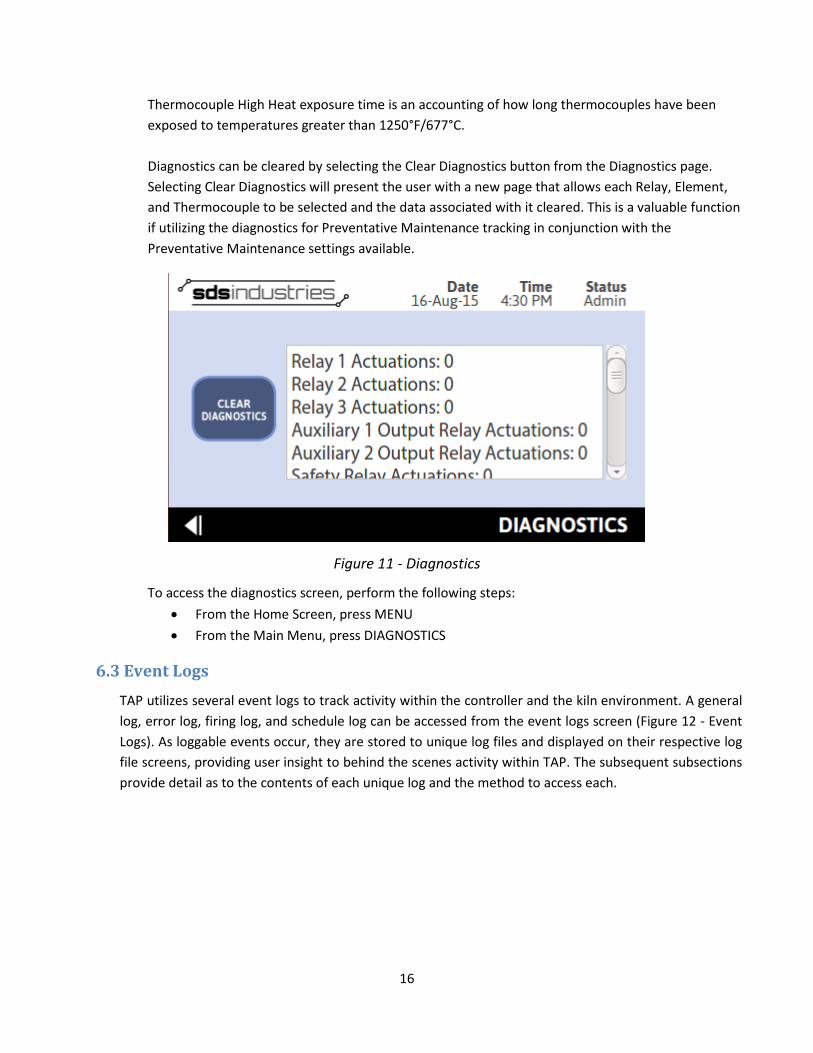
6.2 Diagnostics Diagnostics provide a real-time look into the usage of critical kiln components. From the diagnostics screen (Figure 11 - Diagnostics), you can view the actual number of relay actuations, the amount of time the heating elements have been on, and the amount of time the thermocouples have been exposed to high temperatures. Relay Actuations are captured during each active firing and recorded at the conclusion of the firing. If the controller is not in Dual Mode or Zone Control configurations, Relay 1, Relay 2, and Relay 3 actuations will increment simultaneously, regardless of whether all three relays are present. Auxiliary Output 1 and Auxiliary Output 2 relay actuations will increment each time a user program step explicitly commands the relay to the “On” position, regardless of whether an auxiliary 1 or auxiliary 2 relay is present. The Safety Relay counter will increment once for each firing that occurs, regardless of whether the kiln has a safety relay installed or not. Element on time is an actual recording of the amount of time the elements are turned on during a firing. Unless in Dual Mode or a Zone Control configuration, the values recorded for Element 1, Element 2, and Element 3 will be the same, regardless of the number of elements installed in the kiln.
16
Thermocouple High Heat exposure time is an accounting of how long thermocouples have been exposed to temperatures greater than 1250°F/677°C. Diagnostics can be cleared by selecting the Clear Diagnostics button from the Diagnostics page. Selecting Clear Diagnostics will present the user with a new page that allows each Relay, Element, and Thermocouple to be selected and the data associated with it cleared. This is a valuable function if utilizing the diagnostics for Preventative Maintenance tracking in conjunction with the Preventative Maintenance settings available.
Figure 11 - Diagnostics
To access the diagnostics screen, perform the following steps: • From the Home Screen, press MENU • From the Main Menu, press DIAGNOSTICS
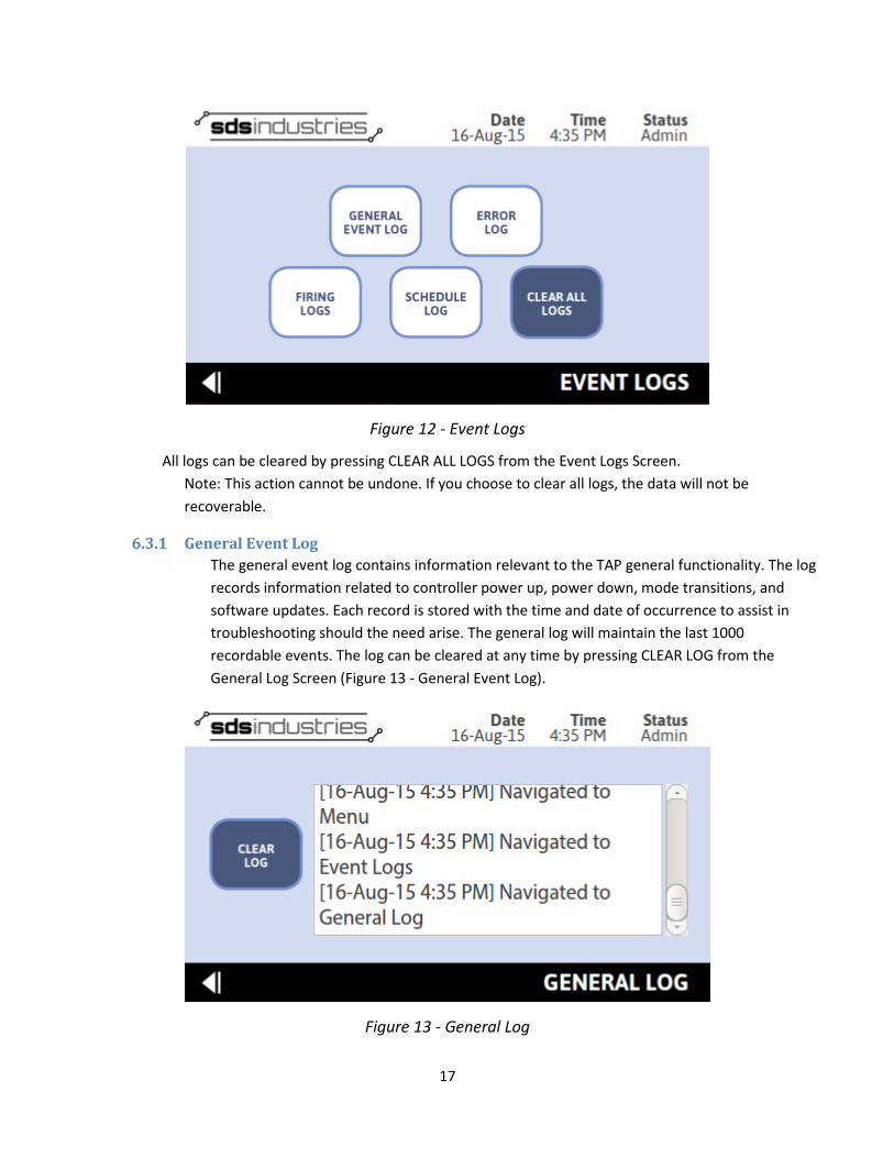
6.3 Event Logs TAP utilizes several event logs to track activity within the controller and the kiln environment. A general log, error log, firing log, and schedule log can be accessed from the event logs screen (Figure 12 - Event Logs). As loggable events occur, they are stored to unique log files and displayed on their respective log file screens, providing user insight to behind the scenes activity within TAP. The subsequent subsections provide detail as to the contents of each unique log and the method to access each.
17
Figure 12 - Event Logs
All logs can be cleared by pressing CLEAR ALL LOGS from the Event Logs Screen. Note: This action cannot be undone. If you choose to clear all logs, the data will not be recoverable.
6.3.1 General Event Log The general event log contains information relevant to the TAP general functionality. The log records information related to controller power up, power down, mode transitions, and software updates. Each record is stored with the time and date of occurrence to assist in troubleshooting should the need arise. The general log will maintain the last 1000 recordable events. The log can be cleared at any time by pressing CLEAR LOG from the General Log Screen (Figure 13 - General Event Log).
Figure 13 - General Log
18
To access the general log, perform the following steps: • From Home Screen, press MENU • From Main Menu, press EVENT LOGS • From Event Logs Screen, press GENERAL LOG
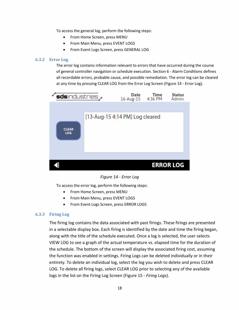
6.3.2 Error Log The error log contains information relevant to errors that have occurred during the course of general controller navigation or schedule execution. Section 6 - Alarm Conditions defines all recordable errors, probable cause, and possible remediation. The error log can be cleared at any time by pressing CLEAR LOG from the Error Log Screen (Figure 14 - Error Log).
Figure 14 - Error Log
To access the error log, perform the following steps: • From Home Screen, press MENU • From Main Menu, press EVENT LOGS • From Event Logs Screen, press ERROR LOGS
6.3.3 Firing Log
The firing log contains the data associated with past firings. These firings are presented in a selectable display box. Each firing is identified by the date and time the firing began, along with the title of the schedule executed. Once a log is selected, the user selects VIEW LOG to see a graph of the actual temperature vs. elapsed time for the duration of the schedule. The bottom of the screen will display the associated firing cost, assuming the function was enabled in settings. Firing Logs can be deleted individually or in their entirety. To delete an individual log, select the log you wish to delete and press CLEAR LOG. To delete all firing logs, select CLEAR LOG prior to selecting any of the available logs in the list on the Firing Log Screen (Figure 15 - Firing Logs).

19
Figure 15 - Firing Logs
To access the firing log, perform the following steps: • From Home Screen, press MENU • From Main Menu, press EVENT LOGS • From Event Logs Screen, press FIRING LOGS • Select a Firing, press VIEW LOG
6.3.4 Schedule Log The schedule log contains a list of all activities associated with schedule creation, modification, and deletion. This log includes the date and time a new schedule is created, along with the associated schedule title, the date and time an existing schedule is modified, along with the associated schedule title, and the date and time any existing schedule is deleted, along with the associated schedule title. The schedule log can be cleared at any time by pressing CLEAR LOG from the Schedule Log Screen (Figure 16 - Schedule Log).

20
Figure 16 - Schedule Log
To access the schedule log, perform the following steps: • From Home Screen, press MENU • From Main Menu, press EVENT LOGS • From Event Logs Screen, press SCHEDULE LOGS
6.4 Schedules The schedules landing page, accessed from the Main Menu while in admin mode, or from the Home Screen while in execute mode, presents the list of available schedules stored in memory, by title. Schedules are populated in alphabetical order, with numbers preceding letters. Unfortunately, some limitation with the ordering does exist, and as such, what most humans consider “natural ordering” is not a possibility. As a result, numbers sequences generally will go 1, 10, 11, …, 2… To avoid this, choose a numbering scheme that implements leading zeros.
From the Schedules screen (Figure 17 – Schedules), accessed from the Menu, or the Schedule Selector screen (Figure 1816 - Schedule Selector), accessed from Home, users have the ability to create a new schedule, edit an existing schedule, or summarily view a currently stored schedule.
Figure 17 – Schedules
21
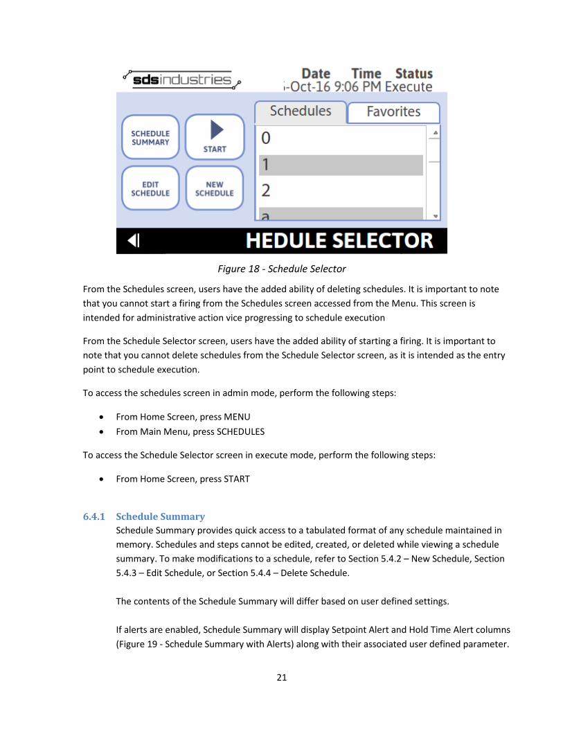
Figure 18 - Schedule Selector
From the Schedules screen, users have the added ability of deleting schedules. It is important to note that you cannot start a firing from the Schedules screen accessed from the Menu. This screen is intended for administrative action vice progressing to schedule execution
From the Schedule Selector screen, users have the added ability of starting a firing. It is important to note that you cannot delete schedules from the Schedule Selector screen, as it is intended as the entry point to schedule execution.
To access the schedules screen in admin mode, perform the following steps:
• From Home Screen, press MENU • From Main Menu, press SCHEDULES
To access the Schedule Selector screen in execute mode, perform the following steps:
• From Home Screen, press START
6.4.1 Schedule Summary Schedule Summary provides quick access to a tabulated format of any schedule maintained in memory. Schedules and steps cannot be edited, created, or deleted while viewing a schedule summary. To make modifications to a schedule, refer to Section 5.4.2 – New Schedule, Section 5.4.3 – Edit Schedule, or Section 5.4.4 – Delete Schedule. The contents of the Schedule Summary will differ based on user defined settings. If alerts are enabled, Schedule Summary will display Setpoint Alert and Hold Time Alert columns (Figure 19 - Schedule Summary with Alerts) along with their associated user defined parameter.

22
Figure 19 - Schedule Summary with Alerts
If Auxiliary Output 1 is enabled, Schedule Summary will display an aux output 1 parameter (Figure 20 - Schedule Summary with Aux 1) for each schedule step.
Figure 20 - Schedule Summary with Aux 1
If Auxiliary Output 2 is enabled, Schedule Summary will display an aux output 2 parameter (Figure 21 - Schedule Summary with Aux 2) for each schedule step.

23
Figure 21 - Schedule Summary with Aux 2
Users may define any combination of these settings, and the user interface will update accordingly. To access the schedule summary screen in administrator mode, perform the following steps:
• From Home Screen, press MENU • From Main Menu, press SCHEDULES • From Schedules Screen, select an available schedule • After an available schedule is selected, press SCHEDULE SUMMARY
To access the schedule summary screen in execute mode, perform the following steps:
• From Home Screen, press MENU • From Schedule Selector screen, select an available schedule • After an available schedule is selected, press SCHEDULE SUMMARY
6.4.2 New Schedule New Schedule creator (Figure 22 - New Schedule) allows the user to input a new schedule while in admin mode, or while in execute mode in preparation for a firing. Schedule storage is virtually unlimited. There is no limit to the number of steps that can be included in a specific schedule. Schedules are stored using the Schedule Title as the identifier; therefore it is important to use unique titles when inputting new schedules. Please be aware, if you input a schedule title that is already in use, TAP will OVERWRITE the existing schedule entry.
24
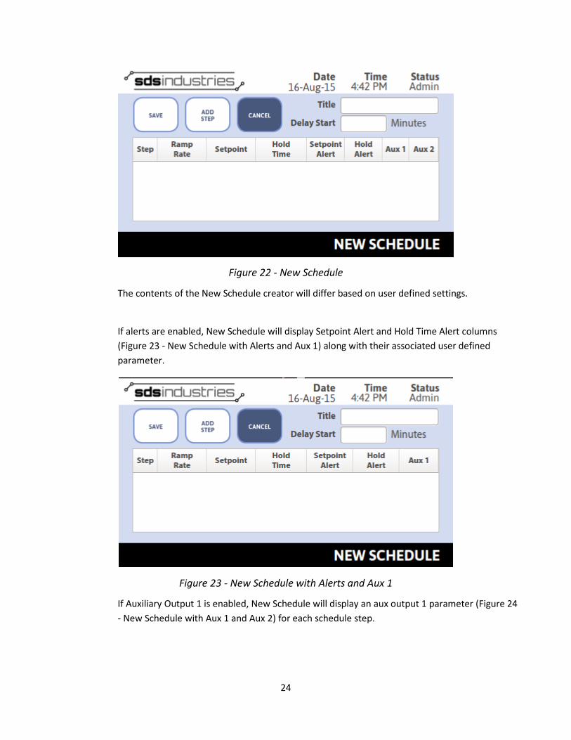
Figure 22 - New Schedule
The contents of the New Schedule creator will differ based on user defined settings.
If alerts are enabled, New Schedule will display Setpoint Alert and Hold Time Alert columns (Figure 23 - New Schedule with Alerts and Aux 1) along with their associated user defined parameter.
Figure 23 - New Schedule with Alerts and Aux 1
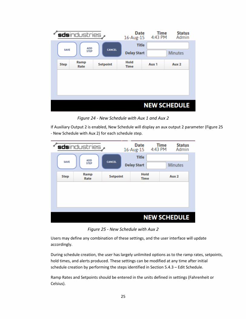
If Auxiliary Output 1 is enabled, New Schedule will display an aux output 1 parameter (Figure 24 - New Schedule with Aux 1 and Aux 2) for each schedule step.
25
Figure 24 - New Schedule with Aux 1 and Aux 2
If Auxiliary Output 2 is enabled, New Schedule will display an aux output 2 parameter (Figure 25 - New Schedule with Aux 2) for each schedule step.
Figure 25 - New Schedule with Aux 2
Users may define any combination of these settings, and the user interface will update accordingly.
During schedule creation, the user has largely unlimited options as to the ramp rates, setpoints, hold times, and alerts produced. These settings can be modified at any time after initial schedule creation by performing the steps identified in Section 5.4.3 – Edit Schedule.
Ramp Rates and Setpoints should be entered in the units defined in settings (Fahrenheit or Celsius).

26
Ramp Rates can be entered from 0.1 to 1500 F/Hr (0.05 to 815 C/Hr). 0.1°F corresponds to the slowest possible programmable ramp rate, while 1500°F corresponds to the fastest programmable ramp rate. Additionally, users can enter 9999 which will ramp the kiln as fast as possible (AFAP). If the ramp is used as a ramp up, this will equate to full power until the setpoint is reached. If the ramp is used as a ramp down, this will equate to no power until the setpoint is reached. If you are unsure of what a ramp rate is, consult your kiln manufacturer or online forums for help. With regards to ramp rates, it is important to remember the following: The kiln cannot always keep up with the defined ramp rate, whether heating or cooling and EVERY KILN IS UNIQUE. A ramp rate of 1500°F, while achievable at a low kiln temperature, is next to impossible at a temperature over 1000°F. In many, cases, it is better to program 9999 (AFAP) in place of a defined ramp rate when kiln temperatures exceed the 1000°F - 1400°F temperature range. This is a case-by-case basis as every kiln is unique. Some kilns may have no problem maintaining a high ramp rate at higher temperatures, while others will struggle mightily. It all comes down the Kiln Power and the volume of space that requires heating.
Setpoints can be entered from 70°F to the Kiln Max Temp. Maximum temperature settings are both firing mode and manufacturer specific. To check the current allowable maximum temperature, review the “current Settings” by navigating, from the Home Screen, to Menu > Settings > Current Settings.
Hold times can be entered in Minutes or Hours and Minutes. If a hold time is entered in the format XXXX, the value will be interpreted as minutes. If a hold time is entered in the format XX.XX, the value will be interpreted as Hours.Minutes. For instance, entering 1.05 for a hold time will be interpreted as 1 Hour and 5 Minutes.
Setpoint Alerts can be enabled or disabled on a per step basis. If your controller is equipped and the alert is enabled, an audible and visual indication will be presented to the user for 60 seconds, or until acknowledged. In all cases, a visual indication will be provided.
Hold Time Alerts can be enabled or disabled on a per step basis. If your controller is equipped and the alert is enabled, an audible and visual indication will be presented to the user for 60 seconds, or until acknowledged. In all cases, a visual indication will be provided.
Aux 1 Output can be enabled or disabled on a per step basis. If enabled, the auxiliary output will be enabled for the duration of the step at which it is specified.
Aux 2 Output can be enabled or disabled on a per step basis. If enabled, the auxiliary output will be enabled for the duration of the step at which it is specified.
To enter a new schedule in administrator/execute mode, perform the following steps: • From Home Screen, press MENU/START • If in admin mode, from Main Menu, press SCHEDULES • From Schedules/Schedule Selector Screen, press NEW SCHEDULE • Highlight SCHEDULE TITLE, and input your chosen title using the virtual keyboard

27
• Highlight DELAY START, and input your chosen delay start time using the virtual keypad • NOTE: This is not a required step. If you leave delay start blank, TAP will use 0 for a delay
time and will start firing immediately after schedule is selected and advanced to execute • Press ADD STEP • Input Ramp Rate using the virtual keypad (Figure 26 - Ramp Rate Entry (°F)), then press
ENTER
Figure 26 - Ramp Rate Entry (°F)
• Input Setpoint using the virtual keypad (Figure 27 - Setpoint Entry (°F)), then press ENTER
28
Figure 27 - Setpoint Entry (°F)
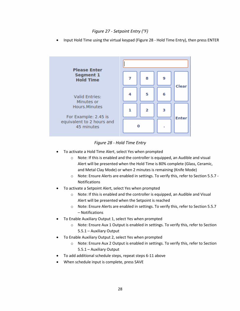
• Input Hold Time using the virtual keypad (Figure 28 - Hold Time Entry), then press ENTER
Figure 28 - Hold Time Entry
• To activate a Hold Time Alert, select Yes when prompted o Note: If this is enabled and the controller is equipped, an Audible and visual
Alert will be presented when the Hold Time is 80% complete (Glass, Ceramic, and Metal Clay Mode) or when 2 minutes is remaining (Knife Mode)
o Note: Ensure Alerts are enabled in settings. To verify this, refer to Section 5.5.7 - Notifications
• To activate a Setpoint Alert, select Yes when prompted o Note: If this is enabled and the controller is equipped, an Audible and Visual
Alert will be presented when the Setpoint is reached o Note: Ensure Alerts are enabled in settings. To verify this, refer to Section 5.5.7
– Notifications • To Enable Auxiliary Output 1, select Yes when prompted
o Note: Ensure Aux 1 Output is enabled in settings. To verify this, refer to Section 5.5.1 – Auxiliary Output
• To Enable Auxiliary Output 2, select Yes when prompted o Note: Ensure Aux 2 Output is enabled in settings. To verify this, refer to Section
5.5.1 – Auxiliary Output • To add additional schedule steps, repeat steps 6-11 above • When schedule input is complete, press SAVE

29
6.4.3 Edit Schedule Schedule editing can be performed while in admin or execute mode. While in execute mode, this can be accomplished prior to schedule execution at the schedule selector page, or during firing from the execute page. It is important to note that schedule steps beyond those that have already been executed as part of a current firing will not be editable. To edit a schedule in admin/execute mode, perform the following steps:
• From Home Screen, press MENU/START • If in admin mode, from Main Menu, press SCHEDULES • From Schedules/Schedule Selector Screen, highlight schedule to be edited, then press
EDIT SCHEDULE o The Edit Schedule Screen will appear with the Schedule Title, Delay Start value,
and Current Schedule in a tabular format o If currently firing, you will not be able to edit the Delay Start value or any
previously executed schedule steps • Highlight values to change • Using the virtual keypad, enter new value, then press ENTER • Once all editing is complete, press SAVE
6.4.4 Delete Schedule Deleting schedules can only be performed in admin mode. If you choose to delete a schedule, please do so at your own risk. There is no way to recover a deleted schedule. To delete a schedule, perform the following steps:
• From Home Screen, press MENU • From Main Menu, press SCHEDULES • From Schedules Screen, highlight schedule for deletion, then press DELETE SCHEDULE • At Confirmation Dialog, press YES
6.4.5 Favorites Both the Schedule Selector and Schedules page incorporate a tab for “Favorites.” Favorites are user defined schedules that are frequently used. To add a schedule to the list of favorites, select it in the Schedules tab, then double tap it with your finger. When successfully added, you will see a popup indication letting you know the task is complete. To remove a schedule from the list of favorites, select it in the Favorites tab, then double tap it with your finger. You will receive a confirmation message to ensure you really want to remove the schedule from your favorites.
6.5 Settings TAP includes a host of settings to make your life easier and to ensure that the data you want to see is available and in the format you prefer. There are also settings which ensure your kiln will continue to operate at peak performance for its entire lifetime. Any time a setting is changed, the value is written to a file. This ensures that, in the event of loss of power, your settings are remembered when the
30
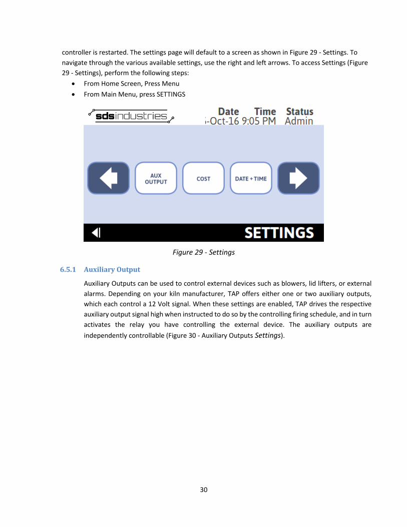
controller is restarted. The settings page will default to a screen as shown in Figure 29 - Settings. To navigate through the various available settings, use the right and left arrows. To access Settings (Figure 29 - Settings), perform the following steps:
• From Home Screen, Press Menu • From Main Menu, press SETTINGS
Figure 29 - Settings
6.5.1 Auxiliary Output
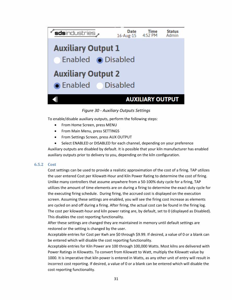
Auxiliary Outputs can be used to control external devices such as blowers, lid lifters, or external alarms. Depending on your kiln manufacturer, TAP offers either one or two auxiliary outputs, which each control a 12 Volt signal. When these settings are enabled, TAP drives the respective auxiliary output signal high when instructed to do so by the controlling firing schedule, and in turn activates the relay you have controlling the external device. The auxiliary outputs are independently controllable (Figure 30 - Auxiliary Outputs Settings).
31
Figure 30 - Auxiliary Outputs Settings
To enable/disable auxiliary outputs, perform the following steps: • From Home Screen, press MENU • From Main Menu, press SETTINGS • From Settings Screen, press AUX OUTPUT • Select ENABLED or DISABLED for each channel, depending on your preference
Auxiliary outputs are disabled by default. It is possible that your kiln manufacturer has enabled auxiliary outputs prior to delivery to you, depending on the kiln configuration.
6.5.2 Cost Cost settings can be used to provide a realistic approximation of the cost of a firing. TAP utilizes the user entered Cost per Kilowatt-Hour and Kiln Power Rating to determine the cost of firing. Unlike many controllers that assume anywhere from a 50-100% duty cycle for a firing, TAP utilizes the amount of time elements are on during a firing to determine the exact duty cycle for the executing firing schedule. During firing, the accrued cost is displayed on the execution screen. Assuming these settings are enabled, you will see the firing cost increase as elements are cycled on and off during a firing. After firing, the actual cost can be found in the firing log. The cost per kilowatt-hour and kiln power rating are, by default, set to 0 (displayed as Disabled). This disables the cost reporting functionality. After these settings are changed they are maintained in memory until default settings are restored or the setting is changed by the user. Acceptable entries for Cost per Kwh are $0 through $9.99. If desired, a value of 0 or a blank can be entered which will disable the cost reporting functionality. Acceptable entries for Kiln Power are 100 through 100,000 Watts. Most kilns are delivered with Power Ratings in Kilowatts. To convert from Kilowatt to Watt, multiply the Kilowatt value by 1000. It is imperative that kiln power is entered in Watts, as any other unit of entry will result in incorrect cost reporting. If desired, a value of 0 or a blank can be entered which will disable the cost reporting functionality.
32
For accrued cost to calculate and display properly, both the Cost per KWh and Kiln Power settings must be entered. If either setting is entered as 0/Disabled, TAP will not calculate the cost of firing. To modify the cost settings, perform the following steps:
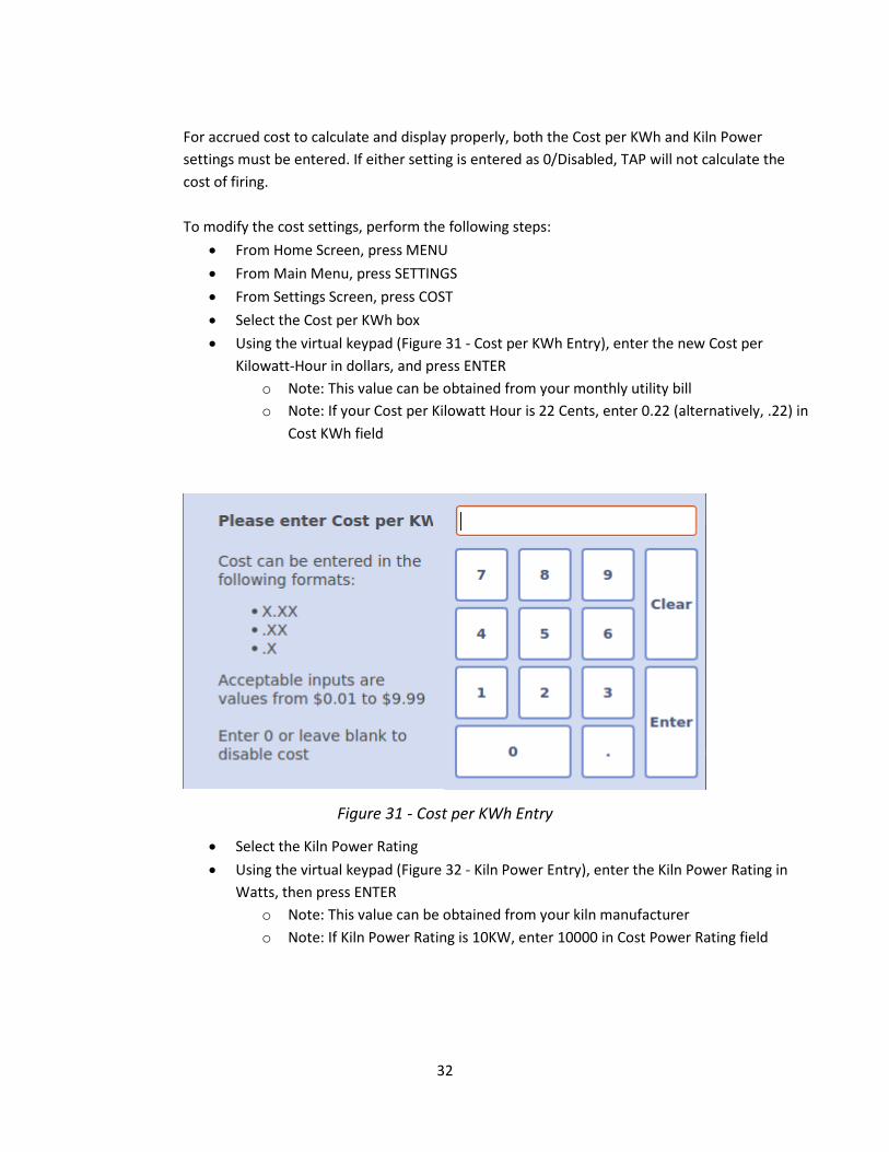
• From Home Screen, press MENU • From Main Menu, press SETTINGS • From Settings Screen, press COST • Select the Cost per KWh box • Using the virtual keypad (Figure 31 - Cost per KWh Entry), enter the new Cost per
Kilowatt-Hour in dollars, and press ENTER o Note: This value can be obtained from your monthly utility bill o Note: If your Cost per Kilowatt Hour is 22 Cents, enter 0.22 (alternatively, .22) in
Cost KWh field
Figure 31 - Cost per KWh Entry
• Select the Kiln Power Rating • Using the virtual keypad (Figure 32 - Kiln Power Entry), enter the Kiln Power Rating in
Watts, then press ENTER o Note: This value can be obtained from your kiln manufacturer o Note: If Kiln Power Rating is 10KW, enter 10000 in Cost Power Rating field

33
Figure 32 - Kiln Power Entry
6.5.3 Date and Time Date and Time settings allow the user to modify the controllers stored date and time. Date and Time is a critical aspect of TAP, as it is used to format event log entries, making it easier for users to sort through previous firings, and making it easier for SDS Industries to retrace steps in the event of anomalous behavior. The Date and Time screen can be used to accomplish these changes (Figure 2 - Date/Time Entry).
To modify the Date or Time, perform the following steps:
• From the Home Screen, Press MENU • From Main Menu, press SETTINGS • From Settings Screen, press Date + Time • Enter the preferred Date and Time (in 24Hr format)
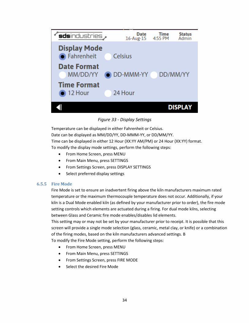
6.5.4 Display Mode Display Settings control how data is displayed to you on the various screens throughout TAP. Within Display Settings, the user has the ability to control the temperature format, the date display format, and the time display format (Figure 33 - Display Settings). These settings are maintained in a file stored in memory and will be retained in the event that power is lost to TAP. The default settings are Fahrenheit temperature display, DD-MMM-YY date display, and 12 Hour clock format.
34
Figure 33 - Display Settings
Temperature can be displayed in either Fahrenheit or Celsius. Date can be displayed as MM/DD/YY, DD-MMM-YY, or DD/MM/YY. Time can be displayed in either 12 Hour (XX:YY AM/PM) or 24 Hour (XX:YY) format. To modify the display mode settings, perform the following steps:
• From Home Screen, press MENU • From Main Menu, press SETTINGS • From Settings Screen, press DISPLAY SETTINGS • Select preferred display settings
6.5.5 Fire Mode Fire Mode is set to ensure an inadvertent firing above the kiln manufacturers maximum rated temperature or the maximum thermocouple temperature does not occur. Additionally, if your kiln is a Dual Mode enabled kiln (as defined by your manufacturer prior to order), the fire mode setting controls which elements are actuated during a firing. For dual mode kilns, selecting between Glass and Ceramic fire mode enables/disables lid elements. This setting may or may not be set by your manufacturer prior to receipt. It is possible that this screen will provide a single mode selection (glass, ceramic, metal clay, or knife) or a combination of the firing modes, based on the kiln manufacturers advanced settings. B To modify the Fire Mode setting, perform the following steps:
• From Home Screen, press MENU • From Main Menu, press SETTINGS • From Settings Screen, press FIRE MODE • Select the desired Fire Mode
35
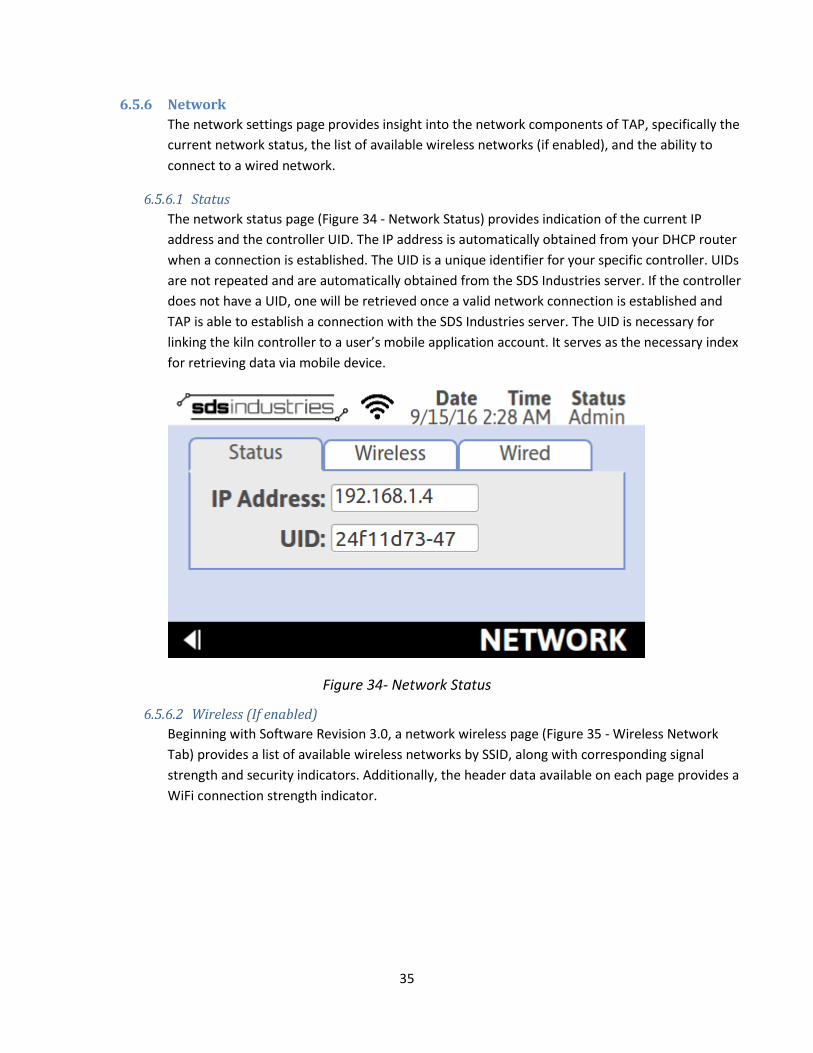
6.5.6 Network The network settings page provides insight into the network components of TAP, specifically the current network status, the list of available wireless networks (if enabled), and the ability to connect to a wired network.
6.5.6.1 Status The network status page (Figure 34 - Network Status) provides indication of the current IP address and the controller UID. The IP address is automatically obtained from your DHCP router when a connection is established. The UID is a unique identifier for your specific controller. UIDs are not repeated and are automatically obtained from the SDS Industries server. If the controller does not have a UID, one will be retrieved once a valid network connection is established and TAP is able to establish a connection with the SDS Industries server. The UID is necessary for linking the kiln controller to a user’s mobile application account. It serves as the necessary index for retrieving data via mobile device.
Figure 34- Network Status
6.5.6.2 Wireless (If enabled) Beginning with Software Revision 3.0, a network wireless page (Figure 35 - Wireless Network Tab) provides a list of available wireless networks by SSID, along with corresponding signal strength and security indicators. Additionally, the header data available on each page provides a WiFi connection strength indicator.

36
Figure 35- Wireless Network Tab
To connect to your preferred network, select the name of the network from the list of available wireless networks. Press “Connect to Network” button. If the selected wireless network had a padlock indicator, TAP will prompt you for a password entry. If no padlock was present, the controller will automatically attempt to establish the connection.
Once the connection status changes, the controller will revert back to the status page. If the connection was successful, an IP address will be populated.
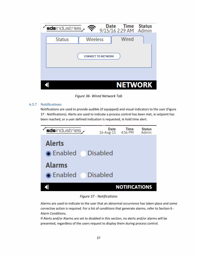
6.5.6.3 Wired The wired network tab (Figure 36 - Wired Network Tab) provides a single button, “Connect to Network,” which will initiate the connection process for a physically wired link. If an Ethernet cable to an internet enabled router is not present, this will fail every time. Once the connection status changes, the control will revert back to the status page. If the connection was successful, an IP address will be populated.
37
Figure 36- Wired Network Tab
6.5.7 Notifications Notifications are used to provide audible (if equipped) and visual indicators to the user (Figure 37 - Notifications). Alerts are used to indicate a process control has been met, ie setpoint has been reached, or a user defined indication is requested, ie hold time alert.
Figure 37 - Notifications
Alarms are used to indicate to the user that an abnormal occurrence has taken place and some corrective action is required. For a list of conditions that generate alarms, refer to Section 6 - Alarm Conditions. If Alerts and/or Alarms are set to disabled in this section, no alerts and/or alarms will be presented, regardless of the users request to display them during process control.

38
It is recommended that alarms remain enabled, however, if they are disabled and an error condition that requires a firing schedule be aborted occurs, the firing will still be aborted though no indication to the user will be present. A recording of the error will be available in the Error Log. To modify the notification settings, perform the following steps:
• From Home Screen, press MENU • From Main Menu, press SETTINGS • From Settings Screen, press NOTIFICATIONS • Select preferred notification settings
6.5.8 Preventative Maintenance
Preventative Maintenance settings (Figure 38 - Preventative Maintenance) are utilized in conjunction with TAP’s recorded diagnostics to ensure peak performance over the lifetime of your kiln. Preventative maintenance settings are used as a reference point for when alerts should be presented to the user and act as a reminder that it is time to perform regular maintenance on the kiln. These settings cover relay life, element life, and thermocouple life.
Figure 38 - Preventative Maintenance
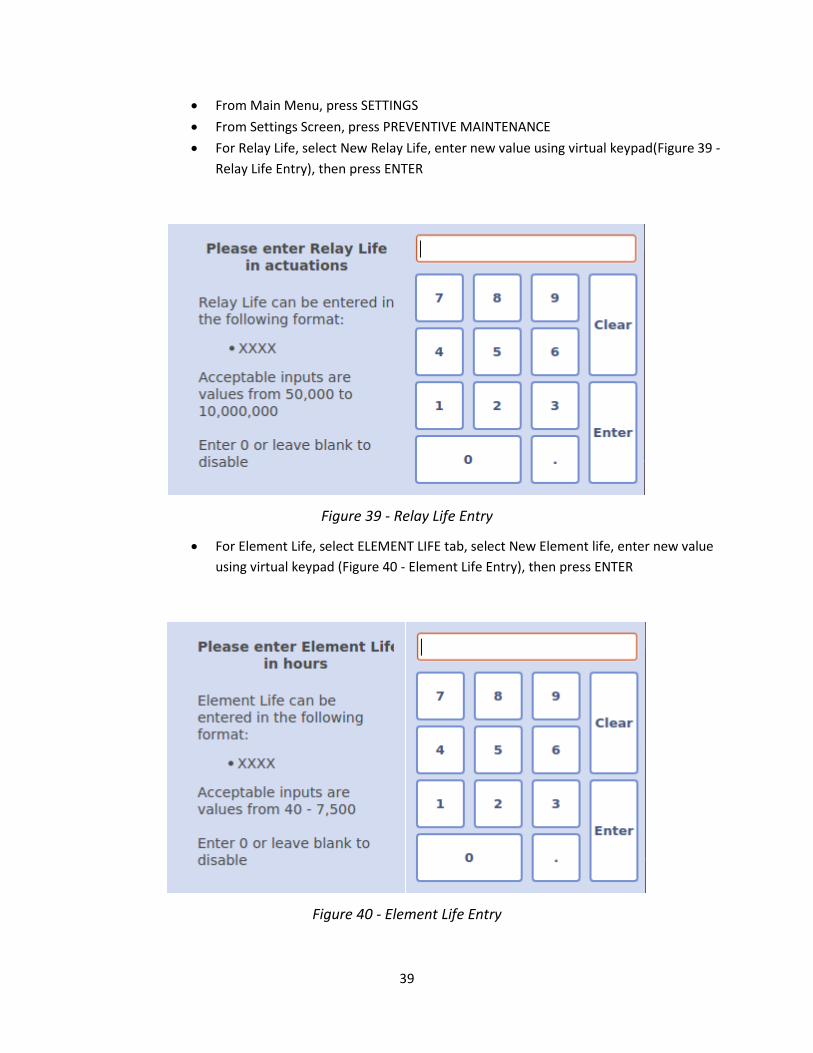
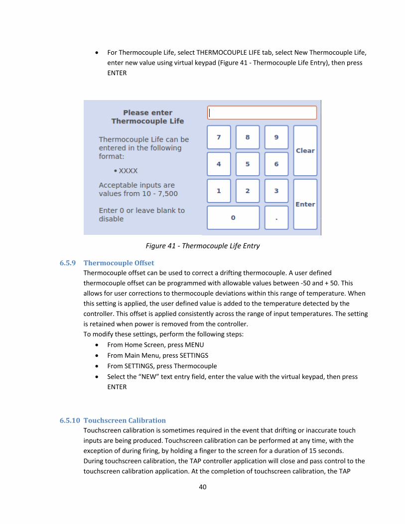
By default, all preventative maintenance settings are disabled. Acceptable entries for Relay Life are 50,000 through 10,000,000 actuations. If desired, a value of 0 or a blank can be entered which will disable the relay life preventative maintenance functionality. Acceptable entries for Element Life are 40 – 7,500 hours. If desired, a value of 0 or blank can be entered which will disable the element life preventative maintenance functionality. Acceptable entries for Thermocouple Life are 10 – 7,500 hours. If desired, a value of 0 or blank can be entered which will disable the thermocouple life preventative maintenance functionality. To modify these settings, perform the following steps:
• From Home Screen, press MENU
39
• From Main Menu, press SETTINGS • From Settings Screen, press PREVENTIVE MAINTENANCE • For Relay Life, select New Relay Life, enter new value using virtual keypad(Figure 39 -
Relay Life Entry), then press ENTER
Figure 39 - Relay Life Entry
• For Element Life, select ELEMENT LIFE tab, select New Element life, enter new value using virtual keypad (Figure 40 - Element Life Entry), then press ENTER
Figure 40 - Element Life Entry
40
• For Thermocouple Life, select THERMOCOUPLE LIFE tab, select New Thermocouple Life, enter new value using virtual keypad (Figure 41 - Thermocouple Life Entry), then press ENTER
Figure 41 - Thermocouple Life Entry
6.5.9 Thermocouple Offset Thermocouple offset can be used to correct a drifting thermocouple. A user defined thermocouple offset can be programmed with allowable values between -50 and + 50. This allows for user corrections to thermocouple deviations within this range of temperature. When this setting is applied, the user defined value is added to the temperature detected by the controller. This offset is applied consistently across the range of input temperatures. The setting is retained when power is removed from the controller. To modify these settings, perform the following steps:
• From Home Screen, press MENU • From Main Menu, press SETTINGS • From SETTINGS, press Thermocouple • Select the “NEW” text entry field, enter the value with the virtual keypad, then press
ENTER
6.5.10 Touchscreen Calibration Touchscreen calibration is sometimes required in the event that drifting or inaccurate touch inputs are being produced. Touchscreen calibration can be performed at any time, with the exception of during firing, by holding a finger to the screen for a duration of 15 seconds. During touchscreen calibration, the TAP controller application will close and pass control to the touchscreen calibration application. At the completion of touchscreen calibration, the TAP
41
controller application will begin again and prompt the user to set the current date and time, or, with software revision 3.0 and later, enter the Home Screen. To perform a touchscreen calibration, perform the following steps:
• From any screen other than Execution, press finger to screen • Wait 15 seconds • Follow on screen prompts
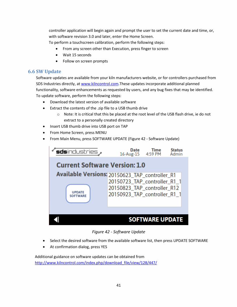
6.6 SW Update Software updates are available from your kiln manufacturers website, or for controllers purchased from SDS Industries directly, at www.kilncontrol.com.These updates incorporate additional planned functionality, software enhancements as requested by users, and any bug fixes that may be identified. To update software, perform the following steps:
• Download the latest version of available software • Extract the contents of the .zip file to a USB thumb drive
o Note: It is critical that this be placed at the root level of the USB flash drive, ie do not extract to a personally created directory
• Insert USB thumb drive into USB port on TAP • From Home Screen, press MENU • From Main Menu, press SOFTWARE UPDATE (Figure 42 - Software Update)
Figure 42 - Software Update
• Select the desired software from the available software list, then press UPDATE SOFTWARE • At confirmation dialog, press YES
Additional guidance on software updates can be obtained from http://www.kilncontrol.com/index.php/download_file/view/128/447/
42
7. Alarm Conditions Kiln Maximum Temperature has been exceeded! Firing is aborted...
This condition can occur during a firing. If this alarm is presented, the kiln temp has exceeded the maximum defined kiln temperature. The default value for Glass Mode is 1700F. The default value for Ceramic Mode is 2300F. If this error condition is met, the controller will abort the firing and disable all outputs. This condition can occur due to:
• A user programming a schedule with a firing temp exceeding the max temp.
• A latched relay resulting in continuous power application to the heating elements.
Kiln is failing to cool! Firing is aborted...
This condition can occur during a firing. If this alarm is presented, the controller has determined that the kiln is not cooling. If this error condition is met, the controller will abort the firing and disable all outputs. The condition can occur due to:
• A user defined temperature that is below the room’s ambient temperature.
• A latched relay resulting in continuous power application to the heating elements.
A high temperature deviation from the hold temp has occurred! Firing is aborted...
This condition can occur during a firing. If this alarm is presented, the controller has determined that the current temperature is greater than 50°F above the current setpoint. If this error condition is met, the controller will abort the firing and disable all outputs. The condition can occur due to:
• A user has opened the kiln during a hold for an extended period of time, resulting in the kiln attempting to generate significant heat to maintain the loss of temperature. (Avoid this by only opening the kiln for short periods if necessary).
• A latched relay resulting in continuous power application to the heating elements.
• An excessively high ramp rate to a low setpoint. This condition can result in significant overshoot, thus triggering the alarm. (Avoid this by using a slower ramp rate to avoid overshoot)
A low temperature deviation from the hold temp has occurred! Firing continues...
This condition can occur during a firing. If this alarm is presented, the controller has determined that the current temperature is less than 50°F below the current setpoint. If this error condition is met, the controller will continue firing. The condition can occur due to:
• A user has opened the kiln during a ramp or hold for an extended period of time.
• Intermittent thermocouple connection resulting in sporadic temperature readings.

43
• A failed relay
• A failed element
Kiln is failing to heat! Firing continues...
This condition can occur during a firing. If this alarm is presented, the controller has determined that the kiln cannot generate enough heat to maintain the user programmed ramp rate. If this error condition is met, the controller will continue firing. The condition can occur due to:
• User programmed Ramp Rate exceeds the capabilities of the kiln.
• A failed relay
• A failed element
• Insufficient power supply for kiln
Kiln is failing to heat for too long. Firing is aborted...
This condition can occur during a firing. If this alarm is presented, the controller has determined that the kiln is not heating or the input is invalid. If this error condition is met, the controller will abort the firing and disable all outputs. The condition can occur due to:
• Disconnected Thermocouple
• Thermocouple not present
• Failed Thermocouple
• Failed Element(s)
• Failed Relay(s)
• Insufficient power supply
• Setpoint temperature greater than capability of kiln
8. Warranty This limited warranty is given only to the immediate purchaser ('Buyer”) of the TAP Kiln Controller Assembly (“5358440-1”). This limited warranty is not transferable. SDS Industries warrants the controller Main Board, CPU Module, Display Board, and LCD Screen installed in the TAP Kiln Controller Assembly to be in good working order under normal operating conditions for a period of three (3) years from the date of purchase. Should the TAP Kiln Controller Assembly fail to be in good working order at any time during the stated three (3) year period, SDS Industries will, at its option, repair or replace the TAP Kiln Controller Assembly as set forth below. The liability of SDS Industries is limited to replacement and/or repair at its factory of the TAP Kiln Controller

44
Assembly that does not remain in good working order. Repair parts will be furnished on an exchange basis and will be either refurbished or new. All replaced parts or products become the property of SDS Industries. Following receipt of notice from Buyer of a valid warranty claim and the TAP Kiln Controller Assembly, SDS Industries will perform its obligations under this limited warranty within 7 business days.
Limited warranty services may be obtained by delivering the TAP Kiln Controller Assembly during the warranty period to your TAP Kiln Controller Supplier or to SDS Industries, INC., 37 Nobody's Road, Cheshire, MA 01225 and providing written proof of purchase and a description of the defect or problem. Buyer will be responsible for shipping and handling incurred by SDS Industries in returning the TAP Kiln Controller Assembly to the Buyer after completion of limited warranty service.
This warranty does not apply to any damage to the TAP Kiln Controller Assembly resulting from:
• Operation beyond electrical rating.
• External sources including, but not limited to, chemicals, heat abuse and improper care.
• Improper or inadequate maintenance by Buyer
• Parts or equipment not supplied by SDS Industries
• Unauthorized modification or misuse.
• Operation outside environmental specifications
• Improper installation
• Over firing (melting of materials being fired) regardless of the cause of the over firing.
TAP Kiln Controller Assemblies returned for service where no warranted defect is found will be subject to service and shipping fees.
If the TAP Kiln Controller Assembly is not in good working order as warranted above, Buyer's sole remedy shall be repair or replacement of the TAP Kiln Controller Assembly as provided above. To the extent permitted by law, ALL EXPRESS AND IMPLIED WARRANTIES FOR THE TAP KILN CONTROLLER ASSEMBLY INCLUDING THE WARRANTIES OF THE MERCHANTABILITY AND FITNESS FOR A PARTICULAR PURPOSE ARE LIMITED TO THE THREE YEAR WARRANTY PERIOD COMMENCING ON THE DATE OF PURCHASE, AND NO OTHER WARRANTY WHETHER EXPRESS OR IMPLIED WILL APPLY TO THIS PERIOD. To the extent permitted by law, SDS INDUSTRIES, INC'S REMEDY AND BUYER'S SOLE REMEDY IS LIMITED SOLELY AND EXCLUSIVELY TO REPAIR OR REPLACEMENT AS SET FORTH HEREIN. SDS INDUSTRIES, INC. SHALL NOT BE LIABLE FOR, AND BUYER'S REMEDY SHALL NOT INCLUDE ANY INCIDENTAL, CONSEQUENTIAL OR OTHER DAMAGES OF ANY KIND WHATSOEVER, WHETHER A CLAIM IS BASED UPON THEORY OF CONTRACT, NEGLIGENCE OR TORT. Buyer shall determine suitability of the TAP Kiln Controller Assembly for the intended use and assume all risk and liability therewith. Some states do not allow this exclusion or limitation of incidental or consequential damages, so the above limitation or exclusion may not apply to you. This warranty gives you specific legal rights, and you may also have other rights which carry from State to State.
The above limitation does not apply in the event that any TAP Kiln Controller Assembly is determined by a court of competent jurisdiction to be defective and to have directly caused bodily injury, death or property

45
damage; provided that in no event shall SDS Industries, INC. liability exceed the greater of $1,200.00 or the purchase price of the specific TAP controller that caused such damage.