Embed Size (px)
Citation preview
The Holodeck: A Parallel Ray-caching Rendering System 1
The Holodeck: A Parallel Ray-caching RenderingSystem
Gregory Ward LarsonSilicon Graphics, Inc.
AbstractThis paper presents a new data structure for light field ren-dering, which resembles a Star Trek holodeck in form andfunction. The grid on a holodeck section acts as a four-dimensional rendering target for a ray tracing algorithm,whose goal is to update an interactive display. A holodeckserver coordinates separate ray evaluation and display proc-esses, optimizing disk and memory usage. Holodeck datamay also be computed off-line, and displayed later with orwithout an interactive ray calculation. Since the renderinghardware is not being taxed by either geometry or lighting,the net result is interactive walk-throughs of complexspaces with arbitrary surface reflection functions.
1. Introduction
An important goal in computer graphics is to producerealistic renderings in real time, simulating a window into avirtual world that the user may alter. As a practical matter,realism and real-time interaction need to be balanced for aparticular application. It may be possible in one case toachieve real-time frame rates by reducing realism to whatthe graphics hardware will support. In another case, wemay be willing to tolerate reduced interactivity to achievethe best-looking or most accurate results. In this paper, weconsider applications where physical accuracy is critical,and we want to get there as fast as we can, provided we doget there eventually. We specifically look at how we canimprove the interactive visualization capabilities of aphysically-based ray tracing solution to global illuminationthrough parallel processing and view ray sample caching.The principal benefit of our method over typical image-based rendering (IBR) approaches is that the entire repre-sentation need not be precomputed before a user can begintouring the scene.
Two basic approaches to interactive ray traced imageryhave emerged over the years. The first approach is toupdate the display progressively as rays are traced for aparticular view. This can be done by simply drawingprogressively smaller rectangles [Painter89], or by usingmore sophisticated representations, such as constrainedDelaunay triangulations and texture maps [Pighin97]. Thesecond approach is to precompute a holographic scenerepresentation, and compress it for quick synthesis ofparticular views [Levoy96] [Gortler96]. The problem withthe first approach is that all information about a particularview is lost once the viewer moves to a new position, wherethe image must be recalculated from scratch. The problem
with the second approach is that all possible views must beprecalculated at the outset, which is inefficient, andprecludes the possibility of iterative scene changes.
In this paper, we present a third approach, which combinesa holographic scene representation with a parallel, interac-tive ray calculation. Rays are computed, cached, andeventually stored to disk using a holodeck data structure --a spatial grid used to sort rays without regard to samplingdensity. These rays are reused for subsequent views, whichmay be refined while the view is stationary. Each ray inter-section distance is recorded along with the floating pointcolor to enhance display processing. This requires a total of10 bytes per sample in our implementation. Rays are clus-tered together into beams for efficient disk access, so nocompression or “development” stage is required. Typicalholodeck files range from 50 Mbytes to 1 Gbyte, dependingon resolution and the number of sections. Although large,these data structures may be kept on CD-ROM or othermass storage devices for rapid access and rerendering, anddo not need to be kept in memory.
We start by describing our method, including the holodeckrepresentation, the three-process program design, and basicdisplay representations. This is followed by an expositionof our results, where we give example scenes, views andtimings. Finally, we conclude with some discussion of thetechnique, and a few ideas for the future.
2. Method
To assure optimal reuse of ray computations, we need adata structure that allows us to rapidly store and retrieve raysamples -- in less time than it would take to recomputethem. We begin with the observation that, although eachray has an origin point corresponding to the eye, its com-puted radiance is valid anywhere along its length, and maybe valid behind the origin as well, so long as there are noobstructions1. Since our goal is to move about in a virtualenvironment, and motion happens most naturally in unob-structed regions, we decided to combine the notion of ahologram with an unobstructed region of free movement,which we call a holodeck section. Rays will pass freelythrough such regions, and their entry and exit points will be
1 The physical unit of radiance is the quantity of light passingthrough a point in a given direction, which is expressed inwatts/steradian/meter2 in Standard International (SI) units.Radiance is constant along an unobstructed ray, which impliesthat there is no participating medium. Although there are ways toovercome this limitation, we will not explore them in this paper.
The Holodeck: A Parallel Ray-caching Rendering System 2
recorded along with their computed values. Any view pointwithin a region will access the rays that pass near it; thusrays will be reused along their length to the greatest extentpossible. This is very similar to the light field andlumigraph constructs presented by Levoy and Hanrahan[Levoy96] and Gortler et al [Gortler96], except that there isno development step -- rays are stored and retrievedinteractively.
The lack of any development step and the need for rapidaccess have two important implications. First, ray samplesare going to take up a lot of space -- since we cannot affordto perform coherency-based compression, everything maynot fit in memory. Second, we require some kind of virtualmemory (VM) management. Although we could leave thistask to the operating system, it was immediately apparentthat the common algorithms for VM management are tooexpensive and inefficient for our needs. We thereforecreated a holodeck server process, which manages one ormore holodeck sections, keeping the most recently used raysamples resident in a finite memory cache.
To compute ray samples, we use the Radiance rtrace pro-gram, which is freely available and does a good job com-puting global illumination in complicated environments[Ward94]. This program also lends itself well to parallelprocessing on multiprocessor and networked systems,which is important for achieving good interactivity.Although we chose to use Radiance, we could have pickedany program that computes ray sample values. The abilityto direct the samples is a plus, but even a pure Monte Carlomethod, which generates random rays in an environment,could be used to fill a holodeck. The end result captures thefull light field, unlike density estimation methods, whichusually to throw away directional information [Shirley95].
Along with each computed radiance, we store the raydistance so we may reproject sample points onto ourdisplayed image. This minimizes image blurring, whichwould otherwise be caused by rays not passing exactlythrough our current view point. There will still be someproblems computing occlusion, but we can address this withsome clever drawing techniques.
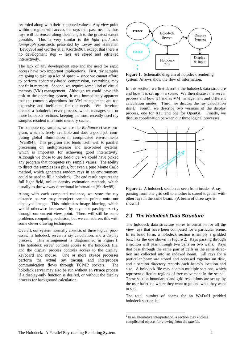
Overall, our system normally consists of three logical proc-esses: a holodeck server, a ray calculation, and a displayprocess. This arrangement is diagrammed in Figure 1.The holodeck server controls access to the holodeck file,and the display process controls access to the display,keyboard and mouse. One or more rtrace processesperform the actual ray tracing, and interprocesscommunication flows through TCP/IP sockets. Theholodeck server may also be run without an rtrace processif a display-only function is desired, or without the displayprocess for background calculation.
HolodeckServer
rtrace
rtrace
DisplayProcess
HolodeckFile
Display& Input
Figure 1. Schematic diagram of holodeck renderingsystem. Arrows show the flow of information.
In this section, we first describe the holodeck data structureand how it is set up in a scene. We then discuss the serverprocess and how it handles VM management and differentcalculation modes. Third, we discuss the ray calculationitself. Fourth, we describe two versions of the displayprocess, one for X11 and one for OpenGL. Finally, wediscuss coordination between our three logical processes.
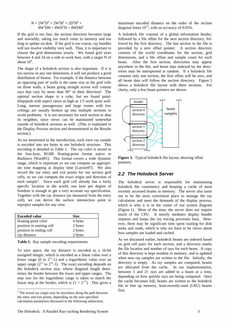
Figure 2. A holodeck section as seen from inside. A raypassing from one grid cell to another is stored together withother rays in the same beam. (A beam of three rays isshown.)
2.1 The Holodeck Data Structure
The holodeck data structure stores information for all theview rays that have been computed for a particular scene.In its basic form, a holodeck section is simply a griddedbox, like the one shown in Figure 2. Rays passing througha section will pass through two cells on two walls. Raysthat pass through the same pair of cells in the same direc-tion are collected into an indexed beam. All rays for aparticular beam are stored and accessed together on disk,and a section directory records each beam’s location andsize. A holodeck file may contain multiple sections, whichrepresent different regions of free movement in the scene2.These section boundaries and grid resolutions are set up bythe user based on where they want to go and what they wantto see.
The total number of beams for an W×D×H griddedholodeck section is:
2 In an alternative interpretation, a section may enclosecomplicated objects for viewing from the outside.
The Holodeck: A Parallel Ray-caching Rendering System 3
N = 2W2D2 + 2W2H2 + 2D2H2 +8W2DH + 8WD2H + 8WDH2
If the grid is too fine, the section directory becomes largeand unwieldy, taking too much room in memory and toolong to update on disk. If the grid is too coarse, ray bundleswill not resolve visibility very well. Thus, it is important tochoose the grid dimensions wisely. We found grid sizesbetween 4 and 24 on a side to work best, with a target N ofabout 106.
The shape of a holodeck section is also important. If it istoo narrow in any one dimension, it will not produce a gooddistribution of beams. For example, if the distance betweenan opposing pair of walls is the same size as the grid cellson those walls, a beam going straight across will containrays that vary by more than 90° in their direction! Theoptimal section shape is a cube, but we found paral-lelepipeds with aspect ratios as high as 1:5 work quite well.Long, narrow passageways and large rooms with lowceilings are usually broken up into multiple sections toavoid problems. It is not necessary for each section to abutits neighbor, since views can be maintained somewhatoutside of holodeck sections as well. (This is explained inthe Display Process section and demonstrated in the Resultssection.)
As we mentioned in the introduction, each view ray sampleis encoded into ten bytes in our holodeck structure. Thisencoding is detailed in Table 1. The ray color is stored inthe four-byte, RGBE floating-point format native toRadiance [Ward91]. This format covers a wide dynamicrange, which is important so we can compute an appropri-ate tone mapping at display time [Larson97]. We alsorecord the ray entry and exit points for our section gridcells, so we can compute the exact origin and direction ofeach sample3. Since each grid cell already has a fairlyspecific location in the world, one byte per degree offreedom is enough to get a very accurate ray specification.Together with the ray distance (as measured from the entrycell), we can derive the surface intersection point toreproject samples for any view.
Encoded value Sizefloating point color 4 bytesposition in starting cell 2 bytesposition in ending cell 2 bytesray distance 2 bytes
Table 1. Ray sample encoding requirements.
To save space, the ray distance is encoded as a 16-bitunsigned integer, which is encoded as a linear value over alower range (0 to 211-1) and a logarithmic value over anupper range (211 to 216-1). The exact encoding depends onthe holodeck section size, whose diagonal length deter-mines the border between the lower and upper ranges. Thestep size for the logarithmic range is taken to match thelinear step at the border, which is (1 + 2-11). This gives a
3 The actual ray origin may be anywhere along the path betweenthe entry and exit points, depending on the user-specifiedcalculation parameters discussed in the following subsection.
maximum encoded distance on the order of the sectiondiagonal times 1013, with an accuracy of 0.05%.
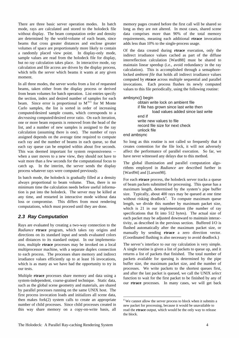
A holodeck file consists of a global information header,followed by a file offset for the next section directory, fol-lowed by the first directory. The last section in the file ispreceded by a zero offset pointer. A section directoryconsists of the world coordinates for the section, griddimensions, and a file offset and sample count for eachbeam. After the first section, directories may appearanywhere in the file, and beam data indexed by the direc-tories may be interspersed at random. If a holodeck filecontains only one section, the first offset will be zero, andall beam data will follow the section directory. Figure 3shows a holodeck file layout with three sections. Forclarity, only a few beam pointers are shown.
header
section 0directory
section 1directory
section 2directory
beamsamples
Figure 3. Typical holodeck file layout, showing offsetpointers.
2.2 The Holodeck Server
The holodeck server is responsible for maintainingholodeck file consistency and keeping a cache of mostrecently accessed beams in memory. The server also turnsout to be the most convenient place to manage the raycalculation and meet the demands of the display process,which is why it is in the center of our system diagram(Figure 1). Most of the time, the server does not requiremuch of the CPU. It merely mediates display bundlerequests and keeps the ray tracing processes busy. How-ever, there may be significant time spent waiting for diskseeks and reads, which is why we have to be clever abouthow samples are loaded and cached.
As we discussed earlier, holodeck beams are indexed basedon grid cell pairs for each section, and a directory marksthe file location and number of rays for each beam. A copyof this directory is kept resident in memory, and is updatedwhen new ray samples are written to the file. Initially, thedirectory is empty. As ray samples are computed, beamsare allocated from the cache. In our implementation,between 1 and 21 rays are added to a beam at a time,depending on how quickly rays are being computed. Oncethe cache becomes full, beams are written to the holodeckfile to free up memory, least-recently-used (LRU) beamsfirst.
The Holodeck: A Parallel Ray-caching Rendering System 4
There are three basic server operation modes. In batchmode, rays are calculated and stored to the holodeck filewithout display. The beam computation order and densityare determined by the world-volume of each beam, sincebeams that cross greater distances and enclose greatervolumes of space are proportionately more likely to containa randomly placed view point. In display-only mode,sample values are read from the holodeck file for display,but no ray calculation takes place. In interactive mode, raycalculation and file access are driven by the display process,which tells the server which beams it wants at any givenmoment.
In all three modes, the server works from a list of requestedbeams, taken either from the display process or derivedfrom beam volumes for batch operation. List entries specifythe section, index and desired number of samples for eachbeam. Since error is proportional to M-0.5 for M MonteCarlo samples, the list is sorted in order of increasingcomputed/desired sample counts, which corresponds to adecreasing computed/desired error ratio. On each iteration,one or more beam requests is removed from the head of thelist, and a number of new samples is assigned to the raycalculation (assuming there is one). The number of raysassigned depends on the average time required to computeeach ray and the number of beams in each queue, so thateach ray queue can be emptied within about five seconds.This was deemed important for system responsiveness --when a user moves to a new view, they should not have towait more than a few seconds for the computational focus tocatch up. In the interim, the server sends the displayprocess whatever rays were computed previously.
In batch mode, the holodeck is gradually filled at a densityalways proportional to beam volume. Thus, there is nominimum time the calculation needs before useful informa-tion is put into the holodeck. The server may be killed atany time, and restarted in interactive mode without dataloss or compromise. This differs from most renderingcomputations, which must proceed until they are done.
2.3 Ray Computation
Rays are evaluated by creating a two-way connection to theRadiance rtrace program, which takes ray origins anddirections on its standard input and sends evaluated colorsand distances to its standard output. In our implementa-tion, multiple rtrace processes may be invoked on a localmultiprocessor machine, with a separate duplex connectionto each process. The processes share memory and indirectirradiance values efficiently up to at least 16 invocations,which is as many as we have had the opportunity to try inour tests.
Multiple rtrace processes share memory and data using asystem-independent, coarse-grained technique. Static data,such as the global scene geometry and materials, are sharedby parallel processes running on the same UNIX host. Thefirst process invocation loads and initializes all scene data,then makes fork(2) system calls to create an appropriatenumber of child processes. Since child processes created inthis way share memory on a copy-on-write basis, all
memory pages created before the first call will be shared solong as they are not altered. In most cases, shared scenedata comprises more than 90% of the total memoryrequirements, meaning each additional rtrace invocationadds less than 10% to the single-process usage.
Of the data created during rtrace execution, only theindirect irradiance values cached as part of the diffuseinterreflection calculation [Ward88] must be shared tomaintain linear speedup (i.e., avoid redundancy in the raycalculation). This is accomplished through a semaphore-locked ambient file that holds all indirect irradiance valuescomputed by rtrace across multiple sequential and parallelinvocations. Each process flushes its newly computedvalues to this file periodically, using the following routine:
ambsync() beginobtain write lock on ambient fileif file has grown since last write then
load values added since last writeend ifwrite new values to filerecord file size for next checkunlock file
end ambsync
So long as this routine is not called so frequently that itcreates contention for the file lock, it will not adverselyaffect the performance of parallel execution. So far, wehave never witnessed any delays due to this method.
The global illumination and parallel computation algo-rithms employed in Radiance are described further in[Ward94] and [Larson98].
For each rtrace process, the holodeck server tracks a queueof beam packets submitted for processing. This queue has amaximum length, determined by the system’s pipe buffersize. Typically, about 400 rays may be queued at one timewithout risking deadlock4. To compute maximum queuelength, we divide this number by maximum packet size,which is 21 in our implementation (the number of rayspecifications that fit into 512 bytes). The actual size ofeach packet may be adjusted downward to maintain interac-tivity, as described in the previous section. Buffered I/O isflushed automatically after the maximum packet size, ormanually by sending rtrace a zero direction vector.(Coordinated flushing is also necessary to avoid deadlock.)
The server’s interface to our ray calculation is very simple.A single routine is given a list of packets to queue up, and itreturns a list of packets that finished. The total number ofpackets available for queuing is determined by the pipebuffer size, the maximum packet size, and the number ofprocesses. We write packets to the shortest queues first,and after the last packet is queued, we call the UNIX selectfunction to wait for the first packet to be finished by any ofour rtrace processes. In many cases, we will get back
4 We cannot allow the server process to block when it submits anew packet for processing, because it would be unavailable toread the rtrace output, which would be the only way to releasethe block.
The Holodeck: A Parallel Ray-caching Rendering System 5
several packets, possibly from more than one process,which are all put in the returned list.
The actual rays traced depend not only on the selectedbeam, but also on a user-set parameter, calledOBSTRUCTIONS. This parameter may be set to True, False,or neither. If True, each ray will begin at a random pointon the beam’s entry cell, and proceed toward a randompoint on its exit cell. This way, the ray is guaranteed tointersect any object lying between its entry and exit point.If OBSTRUCTIONS is False, then the ray begins at the exitpoint, assuring no objects contained within the holodecksection will be visible. If OBSTRUCTIONS is left unset, eachray will have its origin at some random point between theentry and exit points, so it will sometimes intersect aninterior object in its path, and sometimes not.
This ability to control the visibility of interior objects mayseem perverse, but it is actually quite useful. If theholodeck section encloses an object to be viewed from theoutside, then setting OBSTRUCTIONS to True gives us whatwe want. If we plan to be inside each section and renderlocal geometry with an alternate technique, then settingOBSTRUCTIONS to False is clearly the right thing to do. Ifwe plan to view our holodeck from the inside, but we arenot certain that we have excluded all relevant geometryfrom each section, then leaving OBSTRUCTIONS unset ismost reasonable. That way, we will be able to see interiorobjects, but we will also be able to see past them, even ifthey block large areas. Starting a ray at a random distancemeans it will be more likely to intersect an object near theexit wall, which is what we want to see from an interiorviewpoint. In effect, leaving this variable unset gives a softboundary to each holodeck section. Resulting occlusiondiscrepancies will be cleared up in the display algorithms,discussed in section 2.4.3.
Another user parameter controls not what a ray sees, buthow rtrace evaluates distance. If the VDISTANCE parameteris set to False, then rtrace computes the distance to the firstobject that is intersected. If VDISTANCE is set to True, thenrtrace computes the virtual distance for each ray. In thecase of diffuse and curved surfaces, this is the same as thefirst intersection distance. However, when there is a flat,specular surface, such as a mirror or a pane of glass, thenrtrace returns the distance to the object reflected in orvisible through the specular surface. When this intersectionpoint is later reprojected for display, it may give a sharperimage than the first intersection, especially if the sectiongrid is coarse and the program has little time to converge.The disadvantage of using virtual distance is that edges ofspecular objects may break up, and some reprojections maynot be exact, especially if the specular object has a lot ofrefraction. (We show some effects of these user parametersin the Results section.)
Thanks to the simplicity of our queuing model and thenominal demands we place on our ray evaluation, it isstraightforward to adapt this system to different compu-tation environments. We could substitute another raytracing system for Radiance, or use a distributed network ofmachines to perform our calculations rather than amultiprocessor host. Alternatively, we could employ a
massively parallel computer, and communicate over asingle network connection.
2.4 The Display Process
The display process is the most important component of oursystem, because it is responsible for what the user sees andhow the user directs the simulation. Our overall goal is toprovide an interactive walk-through of a realistic environ-ment. For its part, the display process must do thefollowing:• Accept user input and view manipulation,• Tell the holodeck server which beams to compute, and• Create a reasonable image from returned beam
samples.
Of these three tasks, only the second one is unaffected bythe choice of graphics hardware. User input and viewmanipulation vary with the input devices available and theinteraction model; a head-mounted display is different froma CAVE, which is different from a monitor with a spaceballor a mouse. Likewise, the visual representation will changefrom one output device to the next, especially if a stereo-scopic display is available. One of the advantages of oursystem design is the great flexibility it offers in selectingthe ray calculation and display methods.
To simplify our discussion, we will only examine the twocommon graphics configurations we have implemented: acolor X11 display and an OpenGL platform, both with astandard mouse and keyboard. The input and view manipu-lation for these two drivers is identical, so we only discussthe image representations separately.
2.4.1 Input Model
The mouse is used to direct view movement, and thekeyboard is used to enter single-letter commands in thedisplay window. The process starts with a default view inthe center of the first holodeck section (or outside lookingtoward the first section if OBSTRUCTIONS is True). Fromthere, the user usually rotates the view and starts heading insome direction. In forward motion, the view advances 10%closer per frame to whatever object is under the mousecursor as long as the button is held down. The view direc-tion is held constant, and the view center is adjusted sowhatever started out under the cursor will stay there as theview moves. This is extremely helpful in minimizing wild,unintentional view motions as the reference object underthe cursor changes from frame to frame. Similarly, backingaway from or orbiting an object keeps the point under thecursor fixed. Only view rotation, which keeps the vieworigin where it is, avoids the need for any visible geometry.
Even if no geometry is visible, the display driver will draweach of the holodeck section grids during view motion tokeep the user oriented. Often, only part of a new view willbe drawn, since the driver does not request new rays fromthe server until motion has stopped. A cache of ray valuesis kept in the driver’s memory to reduce latency and allowmovement outside the current view. This cache is dis-cussed further in the subsection on Image Representation.
The Holodeck: A Parallel Ray-caching Rendering System 6
Two commands are provided to facilitate interactive scenechanges. A command is provided to kill the rtrace processand another to restart it after some change to the scenedescription. The changes dissolve-fade into the displayedimage as new ray values are entered into the holodeck datastructure. A third command is provided to clear theholodeck contents. This is needed for substantial scenechanges in which ray values change radically.
2.4.2 Beam Selection
Each time a view is selected, the display driver must informthe holodeck server which beams it needs in order to fill inthe image. It is then the server’s responsibility to get asmany rays to the display driver as quickly as possible so wecan display a reasonable image. The server does this byfirst sending whatever rays it happens to have in memory,followed by whatever rays it can find on disk, followed bywhatever new rays are calculated by the ray tracing process.This final stage continues until the screen resolution isachieved, with frequent updates along the way.
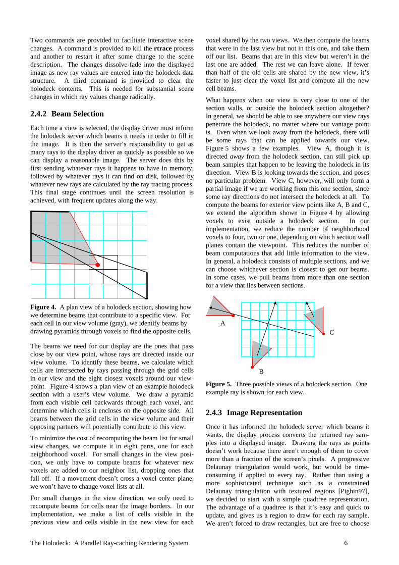
Figure 4. A plan view of a holodeck section, showing howwe determine beams that contribute to a specific view. Foreach cell in our view volume (gray), we identify beams bydrawing pyramids through voxels to find the opposite cells.
The beams we need for our display are the ones that passclose by our view point, whose rays are directed inside ourview volume. To identify these beams, we calculate whichcells are intersected by rays passing through the grid cellsin our view and the eight closest voxels around our view-point. Figure 4 shows a plan view of an example holodecksection with a user’s view volume. We draw a pyramidfrom each visible cell backwards through each voxel, anddetermine which cells it encloses on the opposite side. Allbeams between the grid cells in the view volume and theiropposing partners will potentially contribute to this view.
To minimize the cost of recomputing the beam list for smallview changes, we compute it in eight parts, one for eachneighborhood voxel. For small changes in the view posi-tion, we only have to compute beams for whatever newvoxels are added to our neighbor list, dropping ones thatfall off. If a movement doesn’t cross a voxel center plane,we won’t have to change voxel lists at all.
For small changes in the view direction, we only need torecompute beams for cells near the image borders. In ourimplementation, we make a list of cells visible in theprevious view and cells visible in the new view for each
voxel shared by the two views. We then compute the beamsthat were in the last view but not in this one, and take themoff our list. Beams that are in this view but weren’t in thelast one are added. The rest we can leave alone. If fewerthan half of the old cells are shared by the new view, it’sfaster to just clear the voxel list and compute all the newcell beams.
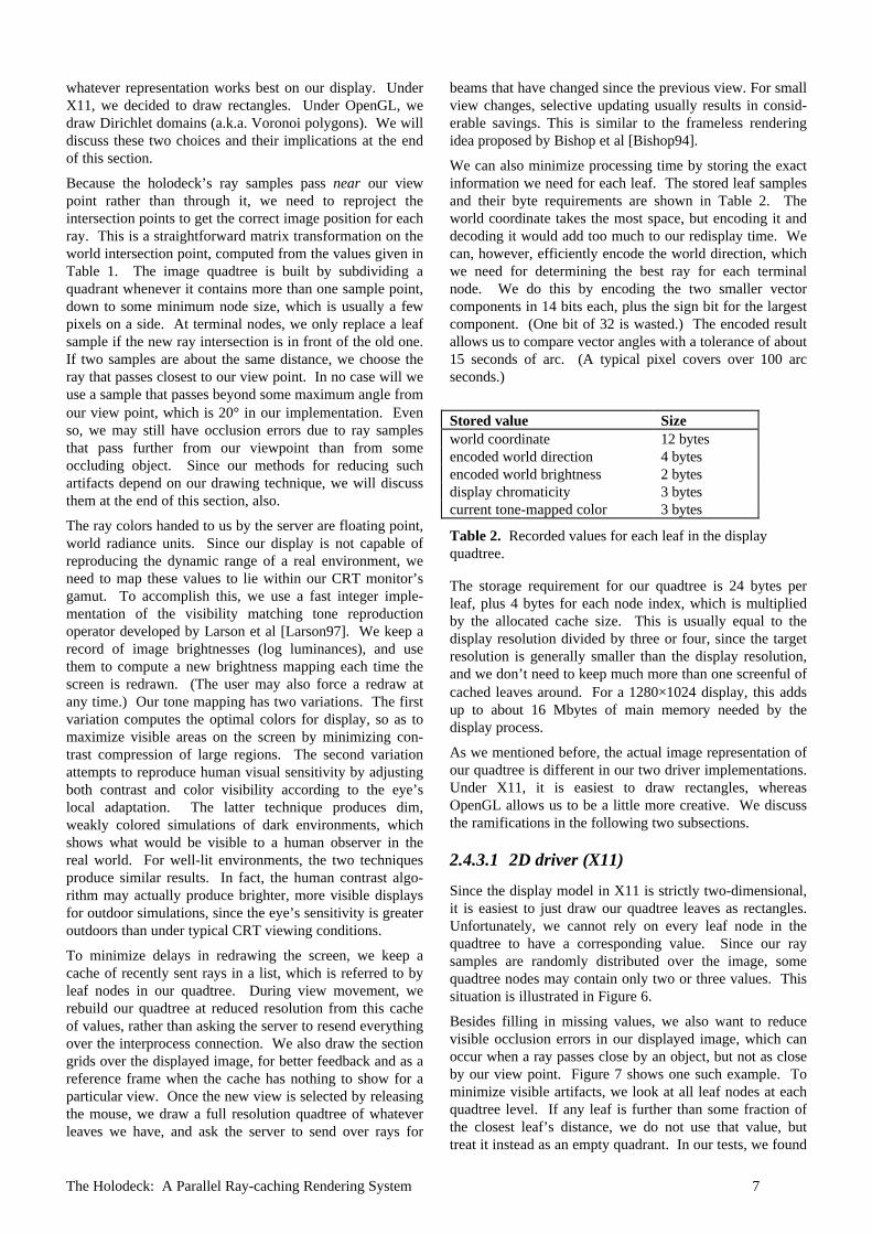
What happens when our view is very close to one of thesection walls, or outside the holodeck section altogether?In general, we should be able to see anywhere our view rayspenetrate the holodeck, no matter where our vantage pointis. Even when we look away from the holodeck, there willbe some rays that can be applied towards our view.Figure 5 shows a few examples. View A, though it isdirected away from the holodeck section, can still pick upbeam samples that happen to be leaving the holodeck in itsdirection. View B is looking towards the section, and posesno particular problem. View C, however, will only form apartial image if we are working from this one section, sincesome ray directions do not intersect the holodeck at all. Tocompute the beams for exterior view points like A, B and C,we extend the algorithm shown in Figure 4 by allowingvoxels to exist outside a holodeck section. In ourimplementation, we reduce the number of neighborhoodvoxels to four, two or one, depending on which section wallplanes contain the viewpoint. This reduces the number ofbeam computations that add little information to the view.In general, a holodeck consists of multiple sections, and wecan choose whichever section is closest to get our beams.In some cases, we pull beams from more than one sectionfor a view that lies between sections.
A
B
C
Figure 5. Three possible views of a holodeck section. Oneexample ray is shown for each view.
2.4.3 Image Representation
Once it has informed the holodeck server which beams itwants, the display process converts the returned ray sam-ples into a displayed image. Drawing the rays as pointsdoesn’t work because there aren’t enough of them to covermore than a fraction of the screen’s pixels. A progressiveDelaunay triangulation would work, but would be time-consuming if applied to every ray. Rather than using amore sophisticated technique such as a constrainedDelaunay triangulation with textured regions [Pighin97],we decided to start with a simple quadtree representation.The advantage of a quadtree is that it’s easy and quick toupdate, and gives us a region to draw for each ray sample.We aren’t forced to draw rectangles, but are free to choose
The Holodeck: A Parallel Ray-caching Rendering System 7
whatever representation works best on our display. UnderX11, we decided to draw rectangles. Under OpenGL, wedraw Dirichlet domains (a.k.a. Voronoi polygons). We willdiscuss these two choices and their implications at the endof this section.
Because the holodeck’s ray samples pass near our viewpoint rather than through it, we need to reproject theintersection points to get the correct image position for eachray. This is a straightforward matrix transformation on theworld intersection point, computed from the values given inTable 1. The image quadtree is built by subdividing aquadrant whenever it contains more than one sample point,down to some minimum node size, which is usually a fewpixels on a side. At terminal nodes, we only replace a leafsample if the new ray intersection is in front of the old one.If two samples are about the same distance, we choose theray that passes closest to our view point. In no case will weuse a sample that passes beyond some maximum angle fromour view point, which is 20° in our implementation. Evenso, we may still have occlusion errors due to ray samplesthat pass further from our viewpoint than from someoccluding object. Since our methods for reducing suchartifacts depend on our drawing technique, we will discussthem at the end of this section, also.
The ray colors handed to us by the server are floating point,world radiance units. Since our display is not capable ofreproducing the dynamic range of a real environment, weneed to map these values to lie within our CRT monitor’sgamut. To accomplish this, we use a fast integer imple-mentation of the visibility matching tone reproductionoperator developed by Larson et al [Larson97]. We keep arecord of image brightnesses (log luminances), and usethem to compute a new brightness mapping each time thescreen is redrawn. (The user may also force a redraw atany time.) Our tone mapping has two variations. The firstvariation computes the optimal colors for display, so as tomaximize visible areas on the screen by minimizing con-trast compression of large regions. The second variationattempts to reproduce human visual sensitivity by adjustingboth contrast and color visibility according to the eye’slocal adaptation. The latter technique produces dim,weakly colored simulations of dark environments, whichshows what would be visible to a human observer in thereal world. For well-lit environments, the two techniquesproduce similar results. In fact, the human contrast algo-rithm may actually produce brighter, more visible displaysfor outdoor simulations, since the eye’s sensitivity is greateroutdoors than under typical CRT viewing conditions.
To minimize delays in redrawing the screen, we keep acache of recently sent rays in a list, which is referred to byleaf nodes in our quadtree. During view movement, werebuild our quadtree at reduced resolution from this cacheof values, rather than asking the server to resend everythingover the interprocess connection. We also draw the sectiongrids over the displayed image, for better feedback and as areference frame when the cache has nothing to show for aparticular view. Once the new view is selected by releasingthe mouse, we draw a full resolution quadtree of whateverleaves we have, and ask the server to send over rays for
beams that have changed since the previous view. For smallview changes, selective updating usually results in consid-erable savings. This is similar to the frameless renderingidea proposed by Bishop et al [Bishop94].
We can also minimize processing time by storing the exactinformation we need for each leaf. The stored leaf samplesand their byte requirements are shown in Table 2. Theworld coordinate takes the most space, but encoding it anddecoding it would add too much to our redisplay time. Wecan, however, efficiently encode the world direction, whichwe need for determining the best ray for each terminalnode. We do this by encoding the two smaller vectorcomponents in 14 bits each, plus the sign bit for the largestcomponent. (One bit of 32 is wasted.) The encoded resultallows us to compare vector angles with a tolerance of about15 seconds of arc. (A typical pixel covers over 100 arcseconds.)
Stored value Sizeworld coordinate 12 bytesencoded world direction 4 bytesencoded world brightness 2 bytesdisplay chromaticity 3 bytescurrent tone-mapped color 3 bytes
Table 2. Recorded values for each leaf in the displayquadtree.
The storage requirement for our quadtree is 24 bytes perleaf, plus 4 bytes for each node index, which is multipliedby the allocated cache size. This is usually equal to thedisplay resolution divided by three or four, since the targetresolution is generally smaller than the display resolution,and we don’t need to keep much more than one screenful ofcached leaves around. For a 1280×1024 display, this addsup to about 16 Mbytes of main memory needed by thedisplay process.
As we mentioned before, the actual image representation ofour quadtree is different in our two driver implementations.Under X11, it is easiest to draw rectangles, whereasOpenGL allows us to be a little more creative. We discussthe ramifications in the following two subsections.
2.4.3.1 2D driver (X11)
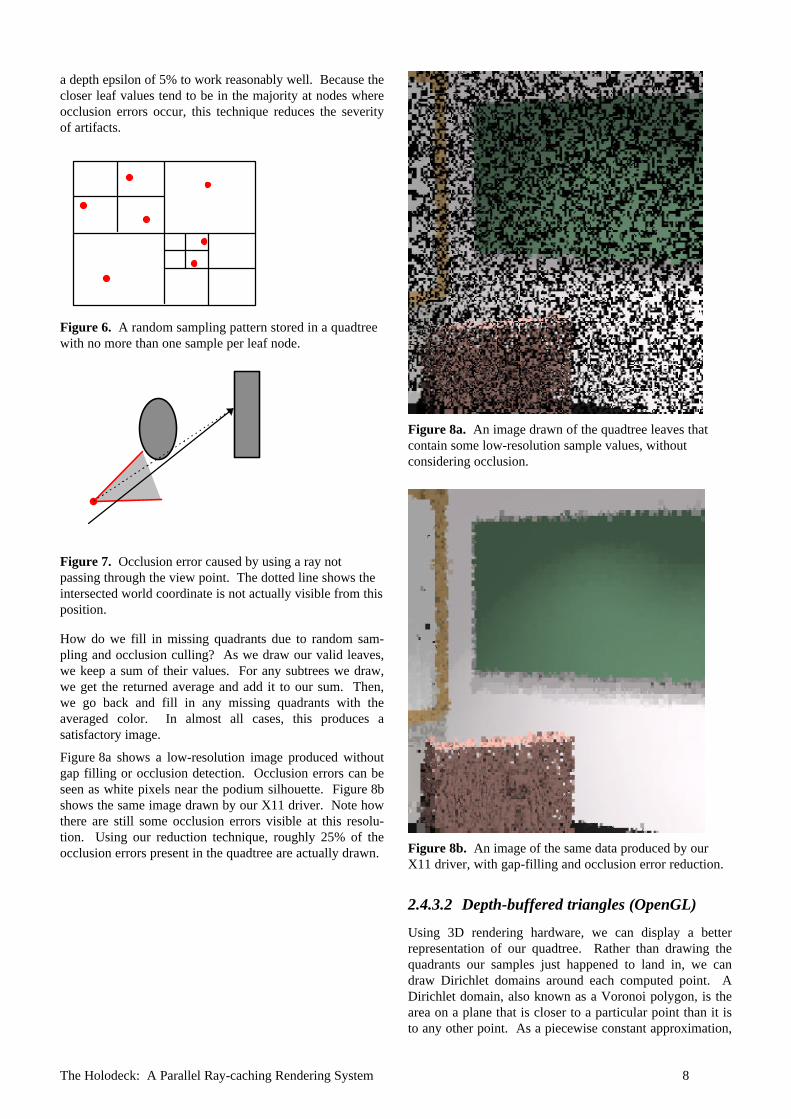
Since the display model in X11 is strictly two-dimensional,it is easiest to just draw our quadtree leaves as rectangles.Unfortunately, we cannot rely on every leaf node in thequadtree to have a corresponding value. Since our raysamples are randomly distributed over the image, somequadtree nodes may contain only two or three values. Thissituation is illustrated in Figure 6.
Besides filling in missing values, we also want to reducevisible occlusion errors in our displayed image, which canoccur when a ray passes close by an object, but not as closeby our view point. Figure 7 shows one such example. Tominimize visible artifacts, we look at all leaf nodes at eachquadtree level. If any leaf is further than some fraction ofthe closest leaf’s distance, we do not use that value, buttreat it instead as an empty quadrant. In our tests, we found
The Holodeck: A Parallel Ray-caching Rendering System 8
a depth epsilon of 5% to work reasonably well. Because thecloser leaf values tend to be in the majority at nodes whereocclusion errors occur, this technique reduces the severityof artifacts.
Figure 6. A random sampling pattern stored in a quadtreewith no more than one sample per leaf node.
Figure 7. Occlusion error caused by using a ray notpassing through the view point. The dotted line shows theintersected world coordinate is not actually visible from thisposition.
How do we fill in missing quadrants due to random sam-pling and occlusion culling? As we draw our valid leaves,we keep a sum of their values. For any subtrees we draw,we get the returned average and add it to our sum. Then,we go back and fill in any missing quadrants with theaveraged color. In almost all cases, this produces asatisfactory image.
Figure 8a shows a low-resolution image produced withoutgap filling or occlusion detection. Occlusion errors can beseen as white pixels near the podium silhouette. Figure 8bshows the same image drawn by our X11 driver. Note howthere are still some occlusion errors visible at this resolu-tion. Using our reduction technique, roughly 25% of theocclusion errors present in the quadtree are actually drawn.
Figure 8a. An image drawn of the quadtree leaves thatcontain some low-resolution sample values, withoutconsidering occlusion.
Figure 8b. An image of the same data produced by ourX11 driver, with gap-filling and occlusion error reduction.
2.4.3.2 Depth-buffered triangles (OpenGL)
Using 3D rendering hardware, we can display a betterrepresentation of our quadtree. Rather than drawing thequadrants our samples just happened to land in, we candraw Dirichlet domains around each computed point. ADirichlet domain, also known as a Voronoi polygon, is thearea on a plane that is closer to a particular point than it isto any other point. As a piecewise constant approximation,
The Holodeck: A Parallel Ray-caching Rendering System 9
the Dirichlet map (i.e., Voronoi diagram) is the least biasedrepresentation possible.
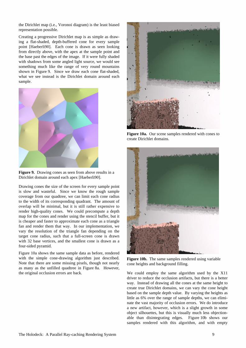
Creating a progressive Dirichlet map is as simple as draw-ing a flat-shaded, depth-buffered cone for every samplepoint [Haeberli90]. Each cone is drawn as seen lookingfrom directly above, with the apex at the sample point andthe base past the edges of the image. If it were fully shadedwith shadows from some angled light source, we would seesomething much like the range of very round mountainsshown in Figure 9. Since we draw each cone flat-shaded,what we see instead is the Dirichlet domain around eachsample.
Figure 9. Drawing cones as seen from above results in aDirichlet domain around each apex [Haeberli90].
Drawing cones the size of the screen for every sample pointis slow and wasteful. Since we know the rough samplecoverage from our quadtree, we can limit each cone radiusto the width of its corresponding quadrant. The amount ofoverlap will be minimal, but it is still rather expensive torender high-quality cones. We could precompute a depthmap for the cones and render using the stencil buffer, but itis cheaper and faster to approximate each cone as a trianglefan and render them that way. In our implementation, wevary the resolution of the triangle fan depending on thetarget cone radius, such that a full-screen cone is drawnwith 32 base vertices, and the smallest cone is drawn as afour-sided pyramid.
Figure 10a shows the same sample data as before, renderedwith the simple cone-drawing algorithm just described.Note that there are some missing pixels, though not nearlyas many as the unfilled quadtree in Figure 8a. However,the original occlusion errors are back.
Figure 10a. Our scene samples rendered with cones tocreate Dirichlet domains.
Figure 10b. The same samples rendered using variablecone heights and background filling.
We could employ the same algorithm used by the X11driver to reduce the occlusion artifacts, but there is a betterway. Instead of drawing all the cones at the same height tocreate true Dirichlet domains, we can vary the cone heightbased on the sample depth value. By varying the heights aslittle as 6% over the range of sample depths, we can elimi-nate the vast majority of occlusion errors. We do introducea new artifact, however, which is a slight growth in someobject silhouettes, but this is visually much less objection-able than disintegrating edges. Figure 10b shows oursamples rendered with this algorithm, and with empty
The Holodeck: A Parallel Ray-caching Rendering System 10
quadtree leaves filled in using average-color, minimum-height cones. Silhouette growth is evident around thepodium, but overall this is a very good impression of ourscene.
2.5 Process Coordination
Good coordination between the holodeck server, the raycalculation, and the display process is needed to keep every-thing running smoothly. We could easily deadlock bywaiting for a process that is waiting for us. To insureagainst this, we use the following process model:• The server waits for ray values to come back from
rtrace, and checks the display process for any requestsusing a non-blocking read once new rays have beendelivered. If there are no further beams to compute,the server waits for input from the display process.
• The display process waits for input from the holodeckserver and the user with equal priority, updating theimage before each call to select.
• The display process is permitted to send short, inter-mittent requests to the server. If the display processhas a long request to make, it first puts in a request forthe server’s attention. While waiting for an acknowl-edgment, the display process continues to load packetssent by the server.
• The display process may request a shut down, but theserver makes the final decision. Once the displayprocess receives a order to shut down, it must quitimmediately.
The above rules are modified if there is no calculationprocess or no display process. If there is no ray calculation,the server waits on the display process alone, sending itwhatever relevant rays it finds in the holodeck file. If thereis no display process, the server creates its own list based onbeam volumes.
While the user is changing views with the mouse, the serverprocess may stall because its socket to the display backs up.This isn’t a problem, though, because the display processwill get back to reading from the server once motion hasceased, and there may be no need for the old beams in thenew view, anyway.
A typical interactive calculation with all three logicalprocesses is detailed in the Appendix.
3. Results
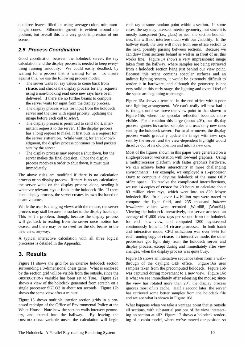
Figure 11 shows the grid for an exterior holodeck sectionsurrounding a 3-dimensional chess game. What is enclosedby the section grid will be visible from the outside, since theOBSTRUCTIONS variable has been set to True. Figure 12ashows a view of the holodeck generated from scratch on asingle processor SGI O2 in about ten seconds. Figure 12bshows the same view after a minute.
Figure 13 shows multiple interior section grids in a pro-posed redesign of the Office of Environmental Policy at theWhite House. Note how the section walls intersect geome-try, and extend into the hallway. By leaving theOBSTRUCTIONS variable unset, the calculation will begin
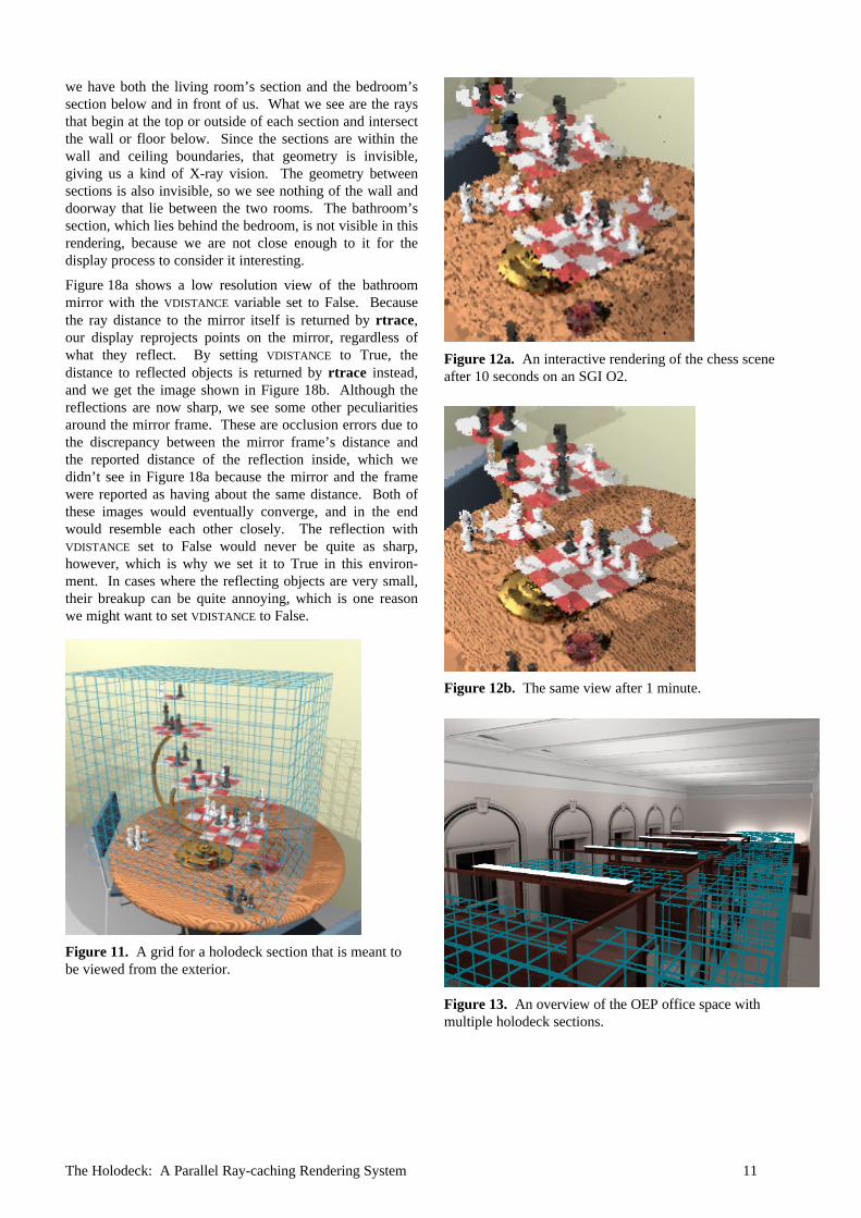
each ray at some random point within a section. In somecases, the ray may intersect interior geometry, but since it ismostly transparent (i.e., glass) or near the section bounda-ries, this will not interfere much with our visibility. In thehallway itself, the user will move from one office section tothe next, possibly passing between sections. Because wecan draw from sections behind as well as in front of us, thisworks fine. Figure 14 shows a very impressionist imagetaken from the hallway, where samples are being retrievedfrom a holodeck section lying just behind our view point.Because this scene contains specular surfaces and anindirect lighting system, it would be extremely difficult torender it in hardware, and although the geometry is notvery solid at this early stage, the lighting and overall feel ofthe space are beginning to emerge.
Figure 15a shows a terminal in the end office with a poortask lighting arrangement. We can’t really tell how bad itis, though, until we move our view point to that shown inFigure 15b, where the specular reflection becomes morevisible. For a rotation this large (about 40°), our displayprocess ignores its cached samples and uses only new onessent by the holodeck server. For smaller moves, the displayprocess would gradually update the image with new rayssent by the server, and the view-dependent highlight woulddissolve out of its old position and into its new one.
Most of the figures shown in this paper were generated on asingle-processor workstation with low-end graphics. Usinga multiprocessor platform with faster graphics hardware,we can achieve better interactivity in more challengingenvironments. For example, we employed a 16-processorOnyx to compute a daytime holodeck of the same OEPoffice space. To resolve the complicated interreflections,we ran 14 copies of rtrace for 20 hours to calculate about83 million view rays, which went into an 820 Mbyteholodeck file. In all, over 1.4 billion rays were traced tocompute the light field, and 235 thousand indirectirradiance values were recorded [Ward88] [Ward94].Viewing the holodeck interactively, our server accessed anaverage of 41,000 view rays per second from the holodeckfor each new view, and computed 1200 rays/secondcontinuously from its 14 rtrace processes. In both batchand interactive mode, CPU utilization was over 99% foreach running copy of rtrace. In interactive mode, the otherprocessors got light duty from the holodeck server anddisplay process, except during and immediately after viewchanges, when the display process was quite busy.
Figure 16 shows an interactive sequence taken from a walk-through of the daylight OEP office. Figure 16a usessamples taken from the precomputed holodeck. Figure 16bwas captured during movement to a new view. Figure 16cis what we see immediately after releasing the mouse; sincethe view has rotated more than 20°, the display processignores most of its cache. Half a second later, the serverhas retrieved some better samples from the holodeck fileand we see what is shown in Figure 16d.
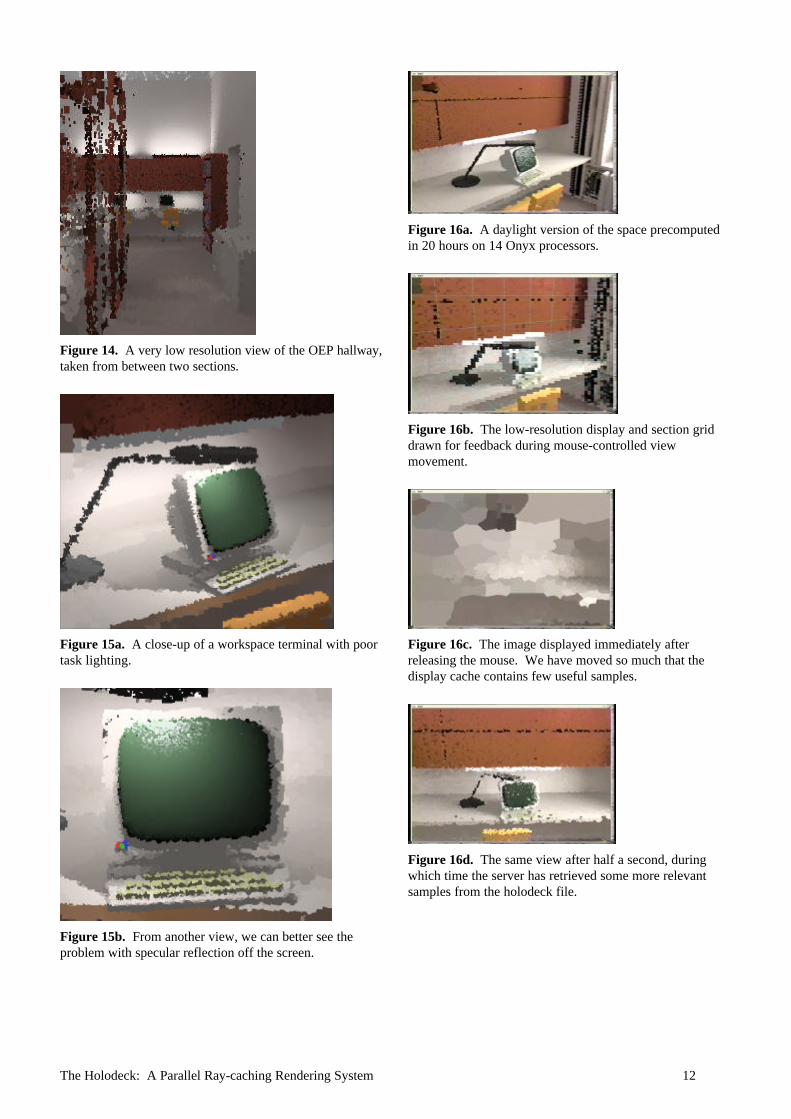
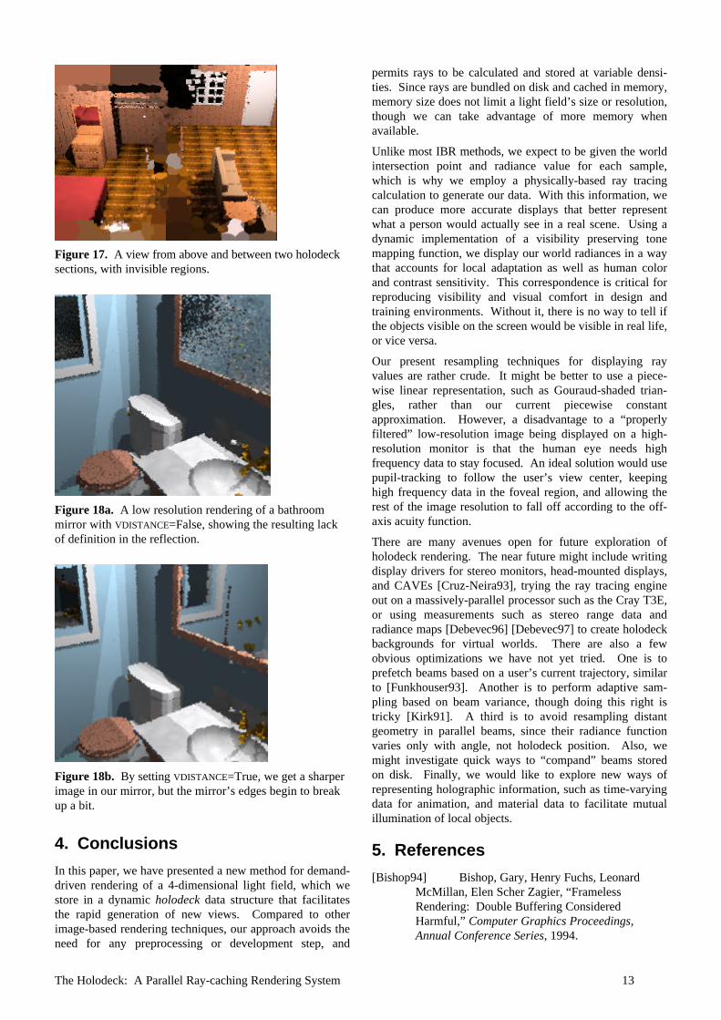
What happens when we take a vantage point that is outsideall sections, with substantial portions of the view intersect-ing no section at all? Figure 17 shows a holodeck render-ing of a cabin model, where we’ve moved our position so
The Holodeck: A Parallel Ray-caching Rendering System 11
we have both the living room’s section and the bedroom’ssection below and in front of us. What we see are the raysthat begin at the top or outside of each section and intersectthe wall or floor below. Since the sections are within thewall and ceiling boundaries, that geometry is invisible,giving us a kind of X-ray vision. The geometry betweensections is also invisible, so we see nothing of the wall anddoorway that lie between the two rooms. The bathroom’ssection, which lies behind the bedroom, is not visible in thisrendering, because we are not close enough to it for thedisplay process to consider it interesting.
Figure 18a shows a low resolution view of the bathroommirror with the VDISTANCE variable set to False. Becausethe ray distance to the mirror itself is returned by rtrace,our display reprojects points on the mirror, regardless ofwhat they reflect. By setting VDISTANCE to True, thedistance to reflected objects is returned by rtrace instead,and we get the image shown in Figure 18b. Although thereflections are now sharp, we see some other peculiaritiesaround the mirror frame. These are occlusion errors due tothe discrepancy between the mirror frame’s distance andthe reported distance of the reflection inside, which wedidn’t see in Figure 18a because the mirror and the framewere reported as having about the same distance. Both ofthese images would eventually converge, and in the endwould resemble each other closely. The reflection withVDISTANCE set to False would never be quite as sharp,however, which is why we set it to True in this environ-ment. In cases where the reflecting objects are very small,their breakup can be quite annoying, which is one reasonwe might want to set VDISTANCE to False.
Figure 11. A grid for a holodeck section that is meant tobe viewed from the exterior.
Figure 12a. An interactive rendering of the chess sceneafter 10 seconds on an SGI O2.
Figure 12b. The same view after 1 minute.
Figure 13. An overview of the OEP office space withmultiple holodeck sections.
The Holodeck: A Parallel Ray-caching Rendering System 12
Figure 14. A very low resolution view of the OEP hallway,taken from between two sections.
Figure 15a. A close-up of a workspace terminal with poortask lighting.
Figure 15b. From another view, we can better see theproblem with specular reflection off the screen.
Figure 16a. A daylight version of the space precomputedin 20 hours on 14 Onyx processors.
Figure 16b. The low-resolution display and section griddrawn for feedback during mouse-controlled viewmovement.
Figure 16c. The image displayed immediately afterreleasing the mouse. We have moved so much that thedisplay cache contains few useful samples.
Figure 16d. The same view after half a second, duringwhich time the server has retrieved some more relevantsamples from the holodeck file.
The Holodeck: A Parallel Ray-caching Rendering System 13
Figure 17. A view from above and between two holodecksections, with invisible regions.
Figure 18a. A low resolution rendering of a bathroommirror with VDISTANCE=False, showing the resulting lackof definition in the reflection.
Figure 18b. By setting VDISTANCE=True, we get a sharperimage in our mirror, but the mirror’s edges begin to breakup a bit.
4. Conclusions
In this paper, we have presented a new method for demand-driven rendering of a 4-dimensional light field, which westore in a dynamic holodeck data structure that facilitatesthe rapid generation of new views. Compared to otherimage-based rendering techniques, our approach avoids theneed for any preprocessing or development step, and
permits rays to be calculated and stored at variable densi-ties. Since rays are bundled on disk and cached in memory,memory size does not limit a light field’s size or resolution,though we can take advantage of more memory whenavailable.
Unlike most IBR methods, we expect to be given the worldintersection point and radiance value for each sample,which is why we employ a physically-based ray tracingcalculation to generate our data. With this information, wecan produce more accurate displays that better representwhat a person would actually see in a real scene. Using adynamic implementation of a visibility preserving tonemapping function, we display our world radiances in a waythat accounts for local adaptation as well as human colorand contrast sensitivity. This correspondence is critical forreproducing visibility and visual comfort in design andtraining environments. Without it, there is no way to tell ifthe objects visible on the screen would be visible in real life,or vice versa.
Our present resampling techniques for displaying rayvalues are rather crude. It might be better to use a piece-wise linear representation, such as Gouraud-shaded trian-gles, rather than our current piecewise constantapproximation. However, a disadvantage to a “properlyfiltered” low-resolution image being displayed on a high-resolution monitor is that the human eye needs highfrequency data to stay focused. An ideal solution would usepupil-tracking to follow the user’s view center, keepinghigh frequency data in the foveal region, and allowing therest of the image resolution to fall off according to the off-axis acuity function.
There are many avenues open for future exploration ofholodeck rendering. The near future might include writingdisplay drivers for stereo monitors, head-mounted displays,and CAVEs [Cruz-Neira93], trying the ray tracing engineout on a massively-parallel processor such as the Cray T3E,or using measurements such as stereo range data andradiance maps [Debevec96] [Debevec97] to create holodeckbackgrounds for virtual worlds. There are also a fewobvious optimizations we have not yet tried. One is toprefetch beams based on a user’s current trajectory, similarto [Funkhouser93]. Another is to perform adaptive sam-pling based on beam variance, though doing this right istricky [Kirk91]. A third is to avoid resampling distantgeometry in parallel beams, since their radiance functionvaries only with angle, not holodeck position. Also, wemight investigate quick ways to “compand” beams storedon disk. Finally, we would like to explore new ways ofrepresenting holographic information, such as time-varyingdata for animation, and material data to facilitate mutualillumination of local objects.
5. References
[Bishop94] Bishop, Gary, Henry Fuchs, LeonardMcMillan, Elen Scher Zagier, “FramelessRendering: Double Buffering ConsideredHarmful,” Computer Graphics Proceedings,Annual Conference Series, 1994.
The Holodeck: A Parallel Ray-caching Rendering System 14
[Cruz-Neira93] Cruz-Neira, Carolina, Daniel Sandin,Thomas DeFanti, “Surround-Screen Projection-Based Virtual Reality: The Design and Implemen-tation of the CAVE,” Computer GraphicsProceedings, Annual Conference Series, 1993.
[Debevec96] Debevec, Paul, Camillo Taylor, JitendraMalik, “Modeling and Rendering Architecturefrom Photographs: A hybrid geometry- andimage-based approach,” Computer GraphicsProceedings, Annual Conference Series, 1996.
[Debevec97] Debevec, Paul, Jitendra Malik,“Recovering High Dynamic Range Radiance Mapsfrom Photographs,” Computer GraphicsProceedings, Annual Conference Series, 1997.
[Fournier95] Fournier, Alain, “From Local to GlobalIllumination and Back,” 6th EurographicsWorkshop on Rendering, Dublin, Ireland, June1995.
[Funkhouser93] Funkhouser, Thomas, Carlo Séquin,“Adaptive Display Algorithm for InteractiveFrame Rates During Visualization of ComplexVirtual Environments,” Computer GraphicsProceedings, Annual Conference Series, 1993.
[Haeberli90], Haeberli, Paul, “Paint by Numbers:Abstract Image Representations,” ComputerGraphics, 24(4), August 1990.
[Kirk91]Kirk, David, James Arvo, “Unbiased SamplingTechniques for Image Synthesis,” ComputerGraphics, 25(4), July 1991.
[Larson97] Larson, Greg Ward, Holly Rushmeier,Christine Piatko, “A Visibility Matching ToneReproduction Operator for High Dynamic RangeScenes,” IEEE Transactions on Visualization andComputer Graphics, December 1997.
[Larson98] Larson, Greg Ward, Rob Shakespeare,Rendering with Radiance: The Art and Science ofLighting Visualization, Morgan Kaufmann, 1998.
[Levoy96] Levoy, Marc and Pat Hanrahan, “LightField Rendering,” Computer GraphicsProceedings, Annual Conference Series, 1996.
[Gortler96] Gortler, Steven, Radek Grzeszczuk,Richard Szeliski, Michael Cohen, “TheLumigraph,” Computer Graphics Proceedings,Annual Conference Series, 1996.
[Painter89] Painter, James and Kenneth Sloan,“Antialiased Ray Tracing by Adaptive ProgressiveRefinement,” Computer Graphics, 23(3), July1989.
[Pighin97] Pighin, Frédéric, Dani Lischinski, DavidSalesin, “Progressive Previewing of Ray-TracedImages Using Image-Plane DiscontinuityMeshing,” 8th Eurographics Workshop onRendering, Saint-Etienne, France, June 1997.
[Shirley95] Shirley, Peter, Bretton Wade, PhilipHubbard, David Zareski, Bruce Walter, Donald
Greenberg, “Global Illumination via Density-Estimation Radiosity,” 6th EurographicsWorkshop on Rendering, Dublin, Ireland, June1995.
[Tumbline93] Tumblin, Jack and Holly Rushmeier.“Tone Reproduction for Realistic Images,” IEEEComputer Graphics and Applications, November1993, 13(6).
[Ward88] Ward, Greg, Francis Rubinstein, RobertClear, “A Ray Tracing Solution for DiffuseInterreflection,” Computer Graphics, 22(4), 1988.
[Ward91] Ward, Greg, “Real Pixels,” in GraphicsGems II, edited by James Arvo, Academic Press,1991.
[Ward94] Ward, Greg, “The RADIANCE LightingSimulation and Rendering System,” ComputerGraphics Proceedings, Annual Conference Series,July 1994.
6. Appendix
The startup sequence for a typical interactive session withthe three logical processes, holodeck server, ray calculationand display, proceeds as follows:1. The user starts the program with two rtrace processes
and an X11 driver.2. The holodeck server opens the existing holodeck, opens
the display driver, and starts two rtrace processes.3. The first rtrace process loads all of its scene files and
octree and initializes its data structure, then forks itself.4. The second rtrace process attaches its i/o descriptors to
the child of the first rtrace, so the processes effectivelyshare memory on a copy-on-write basis.
5. The display driver gets the holodeck section grids fromthe server, and sets up a default view. It computes therelevant beams for this view, and prepares a longrequest for the server.
6. The server, having no beams to work on yet, has beenwaiting on the display process for input.
7. The display process requests the servers attention, andthe server sends an acknowledgment.
8. The display process gets the acknowledgment, andsends its list of beams.
9. The server gets the list of beams, and checks to seewhat it can satisfy from the holodeck file. It sorts thebeams in file order to minimize disk access time, andsends rays to the display process as it loads them fromthe file into memory.
10. The display process loads rays from the server and putsthem into its quadtree, updating the displayed imageevery 50,000 samples (if there are that many).
11. Once the server has exhausted the supply in theholodeck file, it flushes the data to the display processand assigns beams to rtrace on a least-filled/most-requested priority basis.
12. After it has read all the beams sent immediately by theserver, the display process updates the displayed imageand calls select to wait for user input or more serverpackets.
The Holodeck: A Parallel Ray-caching Rendering System 15
13. The server, meanwhile, has called select to wait for oneof the rtrace processes to send it some results.
14. One of the rtrace processes finishes a beam packet andflushes it to the server.
15. The server stores the beam packet in memory, freeingmemory as necessary by writing beams to disk using anLRU scheme.
16. The server flushes the computed samples on to thedisplay process and checks it for input.
17. If there is no request from the display, the serverqueues a new beam packet to rtrace and calls selectagain.
The server continues in this manner, interrupting its tend-ing of rtrace only to fill display requests and manageholodeck file caching. The display process continueshandling input from the server and the user and updatingthe displayed image. When the display process makes ashut down request, the server flushes its queue and closesrtrace, then flushes data to the holodeck file and sends afinal shut down directive to the display. It then waits forthe display process to finish before exiting itself.