Embed Size (px)
Citation preview
The Hobby-Eberly Telescope: Performance upgrades, status, and plans
John A. Bootha, Mark T. Adamsb, Edwin S. Barkerc, Frank N. Basha, James R. Fowlera, John M. Gooda, Gary J. Hilla, Phillip W. Keltona, David L. Lamberta, Phillip J. MacQueena, Povilas
Palunasa, Lawrence W. Ramseyd, Gordon L. Wesleya
aMcDonald Observatory, University of Texas at Austin, 1 University Station C1402, Austin, TX
78712-0259, USA bNational Radio Astronomy Observatory, 520 Edgemont Road, Charlottesville, VA 22901, USA
cNational Aeronautics and Space Administration, Johnson Space Center, Mail Code SX2, Houston, TX 77058, USA
dDepartment of Astronomy and Astrophysics, Pennsylvania State University, University Park, PA 16802, USA
ABSTRACT
The Hobby-Eberly Telescope (HET) is a fixed-elevation, 9.2-m telescope with a spherical primary mirror and a tracker at prime focus to follow astronomical objects. The telescope was constructed for $13.9M over the period 1994-1997. A series of extensive engineering upgrades and corrective actions have been completed recently, resulting in significantly improved delivered image quality and increased operational efficiency. The telescope's Spherical Aberration Corrector (SAC) optics were recoated with a highly reflective and durable broadband coating at Lawrence Livermore National Laboratory. The software mount model that maintains optical alignment of the SAC with the 11-m primary mirror array was recalibrated and improved. The acquisition and guiding optics for both the High Resolution Spectrograph (HRS) and the Low Resolution Spectrograph (LRS) were reworked and improved, allowing for better focus and SAC alignment monitoring and control. Recoating of the primary mirror segment array was begun. Telescope images of 0.82 arcseconds have been recorded for sustained periods in preliminary testing following the engineering upgrade, an improvement of 50% over previous best performance. Additional engineering upgrades are scheduled to consolidate these performance gains and to continue improving delivered image quality, throughput, and telescope operational efficiency. The HET is now capable of the science performance for which it was designed.
Keywords: Hobby-Eberly Telescope, HET, dome seeing, dome ventilation, optical testing, mirror alignment, aluminizing, SAMS, edge sensors, DIMM
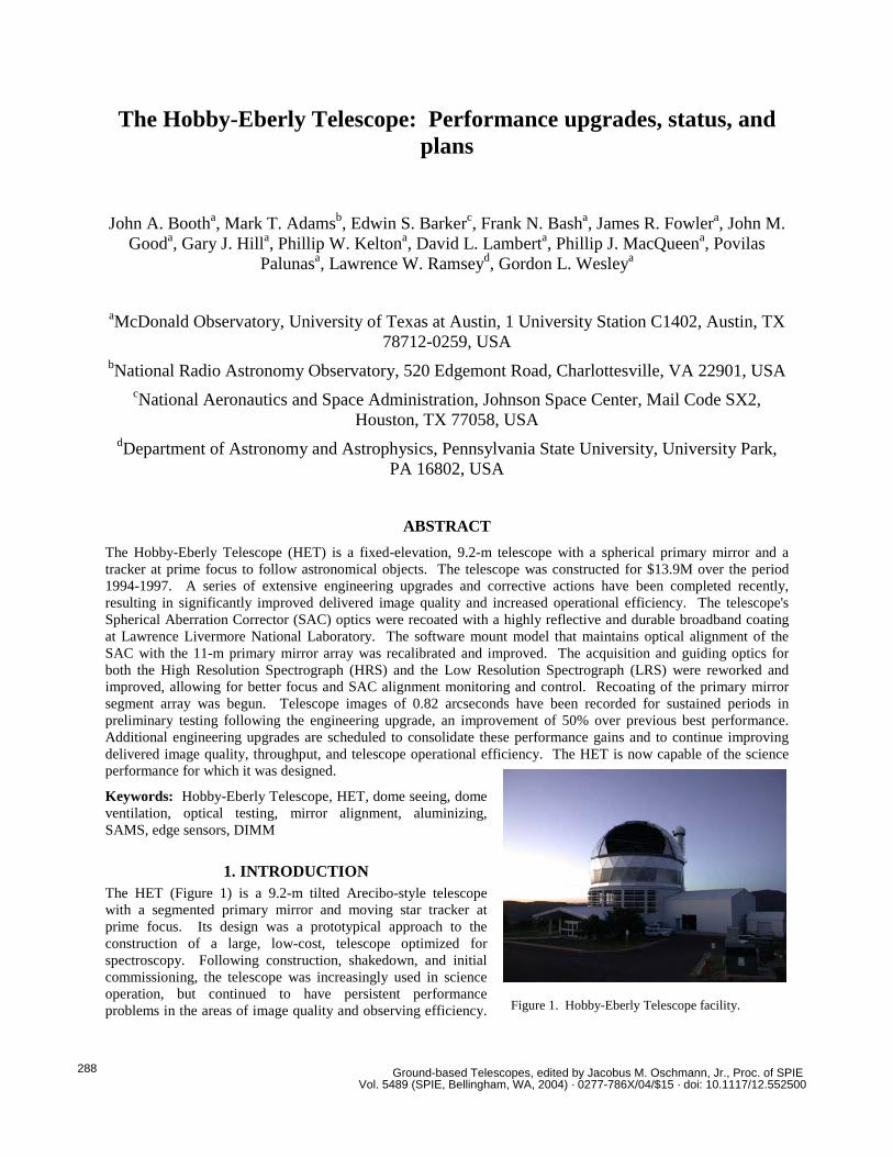
1. INTRODUCTION The HET (Figure 1) is a 9.2-m tilted Arecibo-style telescope with a segmented primary mirror and moving star tracker at prime focus. Its design was a prototypical approach to the construction of a large, low-cost, telescope optimized for spectroscopy. Following construction, shakedown, and initial commissioning, the telescope was increasingly used in science operation, but continued to have persistent performance problems in the areas of image quality and observing efficiency. Figure 1. Hobby-Eberly Telescope facility.
Ground-based Telescopes, edited by Jacobus M. Oschmann, Jr., Proc. of SPIE Vol. 5489 (SPIE, Bellingham, WA, 2004) · 0277-786X/04/$15 · doi: 10.1117/12.552500
288

A concentrated effort was launched in May 2001 to understand and address these problems, with additional manpower and funding, and increased focus on a few key performance areas. This effort was called the HET Completion Project, and it is described elsewhere1. This paper describes the continuation of the Completion Project effort, the progress that has been made, current status of the telescope facility, and our plans for the future.
2. BACKGROUND
2.1. HET Description and History The HET was funded and built by a consortium of five universities, the University of Texas at Austin, the Pennsylvania State University, the Ludwig-Maxmilians Universität München, the Georg-August-Universität Göttingen, and Stanford University. Descriptions of the telescope2, its operation3, scientific instrumentation4,5,6,7, commissioning experience8,9, and early science results10,11 may be found at the indicated references, but a brief description of its operation and history is included here for the reader’s convenience.
The fixed-elevation telescope employs a spherical segmented primary mirror supported by a steel truss as an essential part of the telescope's low-cost, Arecibo-style design concept. All 91 segments are identical regular hexagons. The unique design of the HET allows the primary mirror to remain stationary during an observation; it can be repositioned in azimuth between observations to access different areas of the sky. The mirror has a constant zenith angle of 35 degrees, and thus always has the same orientation with respect to gravity. Images of astronomical objects are acquired and followed across the mirror array at prime focus for up to 2.5 hours by means of a tracking device mounted atop the telescope structure. This unusual mode of operation is somewhat difficult to visualize, and the reader is referred to Figures 2 and 3, below, for a more visual description.
The design simplifies the mirror support problem and significantly reduces the initial cost of the telescope. The construction cost of the HET was $13.9 M, about 15% of the cost of fully steerable telescopes of comparable size. Design and construction time was approximately five years. First light was achieved in December 1996 with seven mirror segments collecting and focusing light through a test optical corrector. Installation of the design corrector in February 1999 and the first facility instrument, the Low Resolution Spectrograph (LRS), in April 1999 were followed by completion of primary mirror segment installation in May 1999. The HET currently is in science
Figure 2. Telescope operation. (Tracker payload and telescope structure are not shown for clarity.) The telescope is pointing south and acquiring an object in the east. Note the large circle on the primary mirror, delineating the telescope entrance pupil on the primary.
Figure 3: Telescope has completed the track begun in Figure 2. Note the illuminated active pupil on the primary mirror. Object is now well past the meridian in the west.
Proc. of SPIE Vol. 5489 289
operations over 90% of the time, with the remaining time used for engineering and instrument commissioning activities.
2.2. Telescope Problems, Status in August 2002 The HET was an ambitious project from its inception, aspiring to build a very large telescope comparatively inexpensively by deliberately limiting some typical telescope capabilities, such as full steerability, to fund an increased primary mirror size. Perhaps not surprisingly for an innovative design on a limited budget, the telescope has had its share of problems. In Phase I of the Completion Project, we addressed dome seeing issues, improved initial segment alignment and segment alignment maintenance, and characterized the HET site seeing for the first time with Differential Image Motion Monitors (DIMMs). Each of these areas produced improvements in telescope performance and our ability to operate the telescope more effectively. However, mean image quality remained stubbornly high at 2.2 arcseconds FWHM, and an image quality “floor” of about 1.5 arcseconds seemed to exist as of August 2002. Telescope image quality below this level was extremely rare, and never better than 1.2 arcseconds. Dome seeing was still suspect, and there were questions about the alignment and figure quality of the mirrors in the Spherical Aberration Corrector (SAC).
3. OPTICAL CHARACTERIZATION
3.1. Project Initiation and Strategy By October 2002, the application of a low emissivity aluminum foil tape to the HET dome was about two-thirds complete (see Section 4.8). Image quality of the telescope, while marginally better, was not radically improved, and it was clear that we had to look beyond dome seeing for the cause of the image quality problem. Hartmann testing in April 2002 was also pointing towards an optical, rather than a local seeing problem.
Phillip MacQueen, head of our Detector Group, was asked to lead an effort to analyze the causes of poor and variable telescope image quality and the apparent lower limit below which the telescope would not image. MacQueen divided the problem into two parts for study, 1) the primary mirror array, and 2) the SAC on the tracker. The primary mirror array was addressed first. Once the array had been adequately characterized, the plan was to proceed to understand any performance issues with the SAC correcting a well-understood primary mirror.
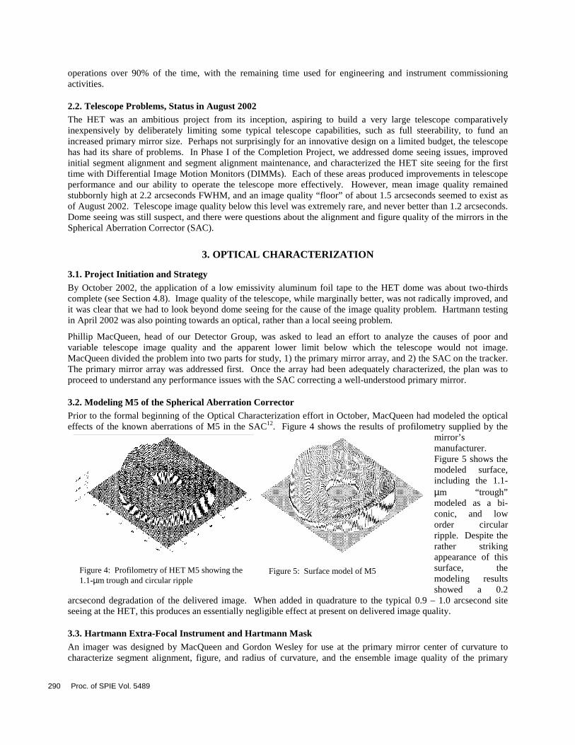
3.2. Modeling M5 of the Spherical Aberration Corrector Prior to the formal beginning of the Optical Characterization effort in October, MacQueen had modeled the optical effects of the known aberrations of M5 in the SAC12. Figure 4 shows the results of profilometry supplied by the
mirror’s manufacturer. Figure 5 shows the modeled surface, including the 1.1-µm “trough” modeled as a bi-conic, and low order circular ripple. Despite the rather striking appearance of this surface, the modeling results showed a 0.2
arcsecond degradation of the delivered image. When added in quadrature to the typical 0.9 – 1.0 arcsecond site seeing at the HET, this produces an essentially negligible effect at present on delivered image quality.
3.3. Hartmann Extra-Focal Instrument and Hartmann Mask An imager was designed by MacQueen and Gordon Wesley for use at the primary mirror center of curvature to characterize segment alignment, figure, and radius of curvature, and the ensemble image quality of the primary
Figure 4: Profilometry of HET M5 showing the 1.1-µm trough and circular ripple
Figure 5: Surface model of M5
290 Proc. of SPIE Vol. 5489
mirror. It also turned out to be useful for measuring the relative reflectivity of individual segments with respect to each other.
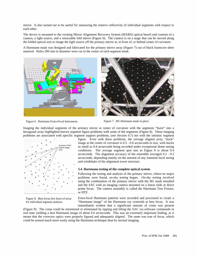
The device is mounted to the existing Mirror Alignment Recovery System (MARS) optical bench and consists of a camera, a light source, and a retractable fold mirror (Figure 6). The camera is on a stage that can be moved along the folded optical axis to image the light source off the primary mirror at, in front of, or behind center of curvature.
A Hartmann mask was designed and fabricated for the primary mirror array (Figure 7) out of black foamcore sheet material. Holes 200 mm in diameter were cut in the center of each segment mask.
Imaging the individual segments of the primary mirror at center of curvature with the segments “burst” into a hexagonal array highlighted known segment figure problems with some of the segments (Figure 8). These imaging problems are associated with specific segment support problems, (see Section 4.7) not with the intrinsic segment
figure. Even with these problems, the average aligned array “stack” image at the center of curvature is 0.5 - 0.6 arcseconds in size, with stacks as small as 0.4 arcseconds being recorded under exceptional dome seeing conditions. The average segment spot size in Figure 8 is about 0.4 arcseconds. The alignment accuracy of the ensemble averaged 0.2 - 0.3 arcseconds, depending mainly on the amount of any transient local seeing and windshake of the alignment tower structure.
3.4. Hartmann testing of the complete optical system Following the testing and analysis of the primary mirror, where no major problems were found, on-sky testing began. On-sky testing involved using the combination of the primary mirror with the M1 mask installed and the SAC with an imaging camera mounted on a linear slide at direct prime focus. The camera assembly is called the Hartmann Test Fixture, or HTF.
Extra-focal Hartmann patterns were recorded and processed to create a “Hartmann image” of the Hartmann ray centroids at best focus. It was immediately evident that a significant amount of coma was present
(Figure 9). The coma could be minimized or eliminated by tipping and tilting the SAC via software commands in real time yielding a best Hartmann image of about 0.6 arcseconds. This was an extremely important finding, as it meant that the corrector optics were properly figured and adequately aligned. The same was true of focus, which could be sensed much more easily using the Hartmann technique than by normal imaging.
Figure 6. Hartmann Extra-Focal Instrument. Figure 7. M1 Hartmann mask in place.
Figure 8. Best-focus hex burst of array for individual segment analysis.
Proc. of SPIE Vol. 5489 291

3.5. Results and Conclusions of Optical Characterization Project To sum up the results of the Optical Characterization effort:
• Primary mirror segment alignment is adequate (0.2 - 0.3 arcseconds) and stable with telescope azimuth motion.
• There are some previously-known segment support problems, but ensemble primary mirror images of 0.4 arcseconds are achievable. Images of 0.5 - 0.6 arcseconds are typical in operation.
• On-sky imaging is dominated by coma and defocus, which can be corrected with tip/tilt and focus movements of the SAC with respect to the primary mirror array.
• With the coma removed by tip/tilting the SAC, the Hartmann image is 0.6 - 0.7 arcseconds FWHM. The specification for the telescope is 0.6 arcseconds.
• Coma and focus problems reappear rapidly once “manually” corrected.
• Original coatings have severely degraded relative to freshly coated aluminum segments. Reflectivity is down about 50%
Out-of-focus images of the primary mirror segments (Figure 10) yielded information about the condition of the original Denton FSS-99 reflective coating. Compared with a two-month old aluminum coating done on-site, the original coatings appeared to show a reflectivity degradation of about 50%. This finding led to the implementation of the Aluminizing Project (see Section 4.6).
Following this testing in April/May 2003, we undertook to make changes to the top end to improve our ability to image at prime focus, and to check the internal alignment of the SAC. The following section details what was done to improve individual subsystems, and the resulting improvements in performance.
4. PERFORMANCE UPGRADES AND RESULTS
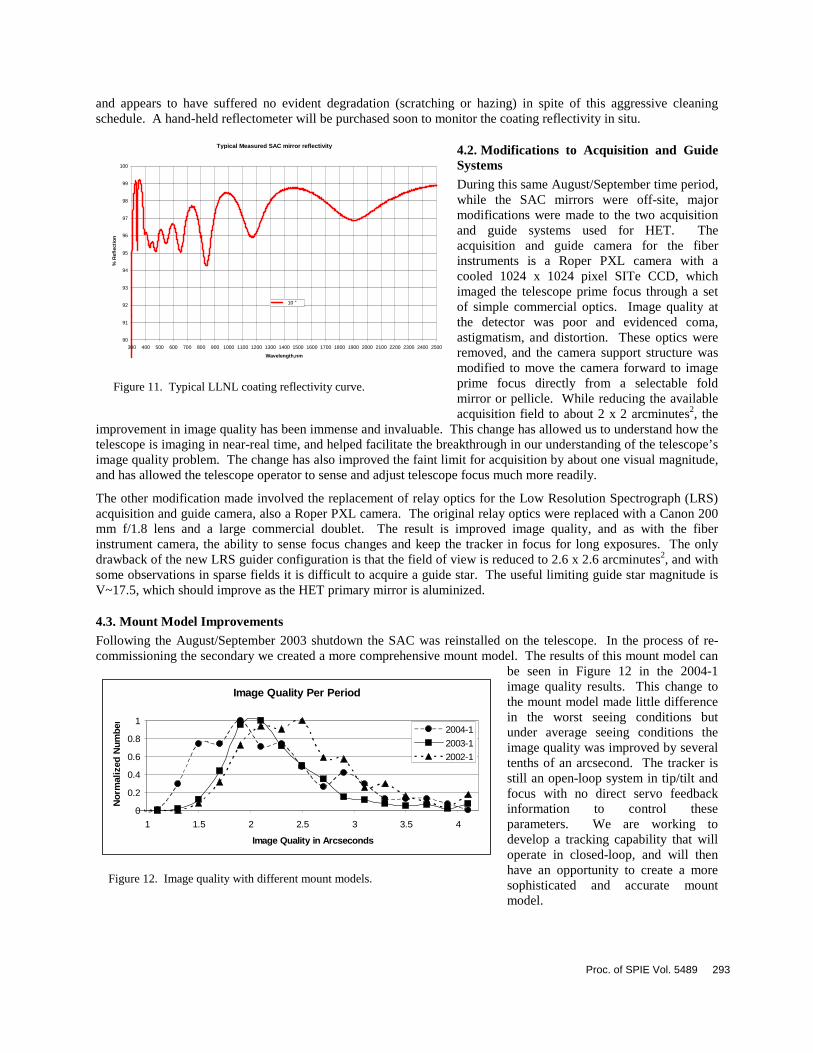
4.1. Spherical Aberration Corrector (SAC) Mirror Recoating The SAC mirrors are well enveloped by their support structure and the HET tracker, making them difficult to access and clean. Further, they are not well protected from the ambient West Texas environment. A regular cleaning program is currently in place, but in August 2003 the SAC mirror reflective coatings had suffered degradation over time from the action of dust and humidity and a lack of cleaning. The decision was taken to remove the SAC mirrors and have them recoated at Lawrence Livermore National Laboratory (LLNL). LLNL has developed a durable reflective coating13 for use by internal customers, and agreed to recoat the SAC mirrors on a best effort basis. Recoating was accomplished during the month of August 2003, and the resultant typical reflectivity is presented in Figure 11.
Our experience thus far with the new coatings has been positive. The SAC is cleaned approximately once per week,
Figure 10. Out-of-focus primary image.
Figure 9. Hartmann image showing classic coma with primary mirror outer ring displaced to the left.
292 Proc. of SPIE Vol. 5489
and appears to have suffered no evident degradation (scratching or hazing) in spite of this aggressive cleaning schedule. A hand-held reflectometer will be purchased soon to monitor the coating reflectivity in situ.
4.2. Modifications to Acquisition and Guide Systems During this same August/September time period, while the SAC mirrors were off-site, major modifications were made to the two acquisition and guide systems used for HET. The acquisition and guide camera for the fiber instruments is a Roper PXL camera with a cooled 1024 x 1024 pixel SITe CCD, which imaged the telescope prime focus through a set of simple commercial optics. Image quality at the detector was poor and evidenced coma, astigmatism, and distortion. These optics were removed, and the camera support structure was modified to move the camera forward to image prime focus directly from a selectable fold mirror or pellicle. While reducing the available acquisition field to about 2 x 2 arcminutes2, the
improvement in image quality has been immense and invaluable. This change has allowed us to understand how the telescope is imaging in near-real time, and helped facilitate the breakthrough in our understanding of the telescope’s image quality problem. The change has also improved the faint limit for acquisition by about one visual magnitude, and has allowed the telescope operator to sense and adjust telescope focus much more readily.
The other modification made involved the replacement of relay optics for the Low Resolution Spectrograph (LRS) acquisition and guide camera, also a Roper PXL camera. The original relay optics were replaced with a Canon 200 mm f/1.8 lens and a large commercial doublet. The result is improved image quality, and as with the fiber instrument camera, the ability to sense focus changes and keep the tracker in focus for long exposures. The only drawback of the new LRS guider configuration is that the field of view is reduced to 2.6 x 2.6 arcminutes2, and with some observations in sparse fields it is difficult to acquire a guide star. The useful limiting guide star magnitude is V~17.5, which should improve as the HET primary mirror is aluminized.
4.3. Mount Model Improvements Following the August/September 2003 shutdown the SAC was reinstalled on the telescope. In the process of re-commissioning the secondary we created a more comprehensive mount model. The results of this mount model can
be seen in Figure 12 in the 2004-1 image quality results. This change to the mount model made little difference in the worst seeing conditions but under average seeing conditions the image quality was improved by several tenths of an arcsecond. The tracker is still an open-loop system in tip/tilt and focus with no direct servo feedback information to control these parameters. We are working to develop a tracking capability that will operate in closed-loop, and will then have an opportunity to create a more sophisticated and accurate mount model.
Typical Measured SAC mirror reflectivity
90
91
92
93
94
95
96
97
98
99
100
300 400 500 600 700 800 900 1000 1100 1200 1300 1400 1500 1600 1700 1800 1900 2000 2100 2200 2300 2400 2500
Wavelength,nm
%
Ref
lect
ion
10 "
Figure 11. Typical LLNL coating reflectivity curve.
Image Quality Per Period
0
0.2
0.4
0.6
0.8
1
1 1.5 2 2.5 3 3.5 4
Image Quality in Arcseconds
Nor
mal
ized
Num
ber
2004-1
2003-1
2002-1
Figure 12. Image quality with different mount models.
Proc. of SPIE Vol. 5489 293
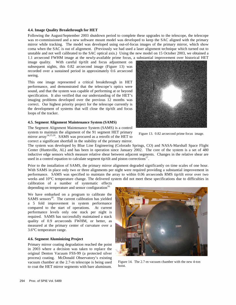
4.4. Image Quality Breakthrough for HET Following the August/September 2003 shutdown period to complete these upgrades to the telescope, the telescope was re-commissioned and a new software mount model was developed to keep the SAC aligned with the primary mirror while tracking. The model was developed using out-of-focus images of the primary mirror, which show coma when the SAC is out of alignment. (Previously we had used a laser alignment technique which turned out to unstable and not well calibrated to the SAC optical axis.) Using the new model on 15 October 2003, we obtained a 1.1 arcsecond FWHM image at the newly-available prime focus, a substantial improvement over historical HET image quality. With careful tip/tilt and focus adjustment on subsequent nights, this 0.82 arcsecond image (Figure 13) was recorded over a sustained period in approximately 0.6 arcsecond seeing.
This one image represented a critical breakthrough in HET performance, and demonstrated that the telescope’s optics were sound, and that the system was capable of performing at or beyond specification. It also verified that our understanding of the HET’s imaging problems developed over the previous 12 months was correct. Our highest priority project for the telescope currently is the development of systems that will close the tip/tilt and focus loops of the tracker.
4.5. Segment Alignment Maintenance System (SAMS) The Segment Alignment Maintenance System (SAMS) is a control system to maintain the alignment of the 91 segment HET primary mirror array14,15,16. SAMS was procured as a retrofit of the HET to correct a significant shortfall in the stability of the primary mirror. The system was developed by Blue Line Engineering (Colorado Springs, CO) and NASA-Marshall Space Flight Center (Huntsville, AL) and has been in operation since January 2002. The core of the system is a set of 480 inductive edge sensors which measure relative shear between adjacent segments. Changes in the relative shear are used in a control equation to calculate segment tip/tilt and piston corrections17.
Prior to the installation of SAMS, the primary mirror alignment degraded significantly on time scales of one hour. With SAMS in place only two or three alignments per night were required providing a substantial improvement in performance. SAMS was specified to maintain the array to within 0.06 arcseconds RMS tip/tilt error over two weeks and 10°C temperature change. The delivered system did not meet these specifications due to difficulties in calibration of a number of systematic effects depending on temperature and sensor configuration16.
We have embarked on a program to calibrate the SAMS sensors18. The current calibration has yielded a 5 fold improvement in system performance compared to the start of operations. At current performance levels only one stack per night is required. SAMS has successfully maintained a stack quality of 0.9 arcseconds FWHM, or better, as measured at the primary center of curvature over a 3.6°C temperature range.
4.6. Segment Aluminizing Project Primary mirror coating degradation reached the point in 2003 where a decision was taken to replace the original Denton Vacuum FSS-99 (a protected silver process) coating. McDonald Observatory’s existing vacuum chamber at the 2.7-m telescope is being used to coat the HET mirror segments with bare aluminum.
Figure 14. The 2.7-m vacuum chamber with the new 4-ton hoist.
Figure 13. 0.82 arcsecond prime focus image.
294 Proc. of SPIE Vol. 5489
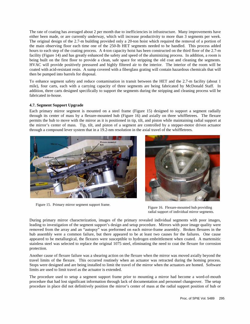
The rate of coating has averaged about 2 per month due to inefficiencies in infrastructure. Many improvements have either been made, or are currently underway, which will increase productivity to more than 3 segments per week. The original design of the 2.7-m building provided only a 20-ton hoist which required the removal of a portion of the main observing floor each time one of the 250-lb HET segments needed to be handled. This process added hours to each step of the coating process. A 4-ton capacity hoist has been constructed on the third floor of the 2.7-m facility (Figure 14) and has greatly enhanced the safety and speed of the aluminizing process. In addition, a room is being built on the first floor to provide a clean, safe space for stripping the old coat and cleaning the segments. HVAC will provide positively pressured and highly filtered air to the interior. The interior of the room will be coated with acid-resistant resin. A sump covered with a fiberglass grating will contain hazardous chemicals that will then be pumped into barrels for disposal.
To enhance segment safety and reduce contamination in transit between the HET and the 2.7-m facility (about 1 mile), four carts, each with a carrying capacity of three segments are being fabricated by McDonald Staff. In addition, three carts designed specifically to support the segments during the stripping and cleaning process will be fabricated in-house.
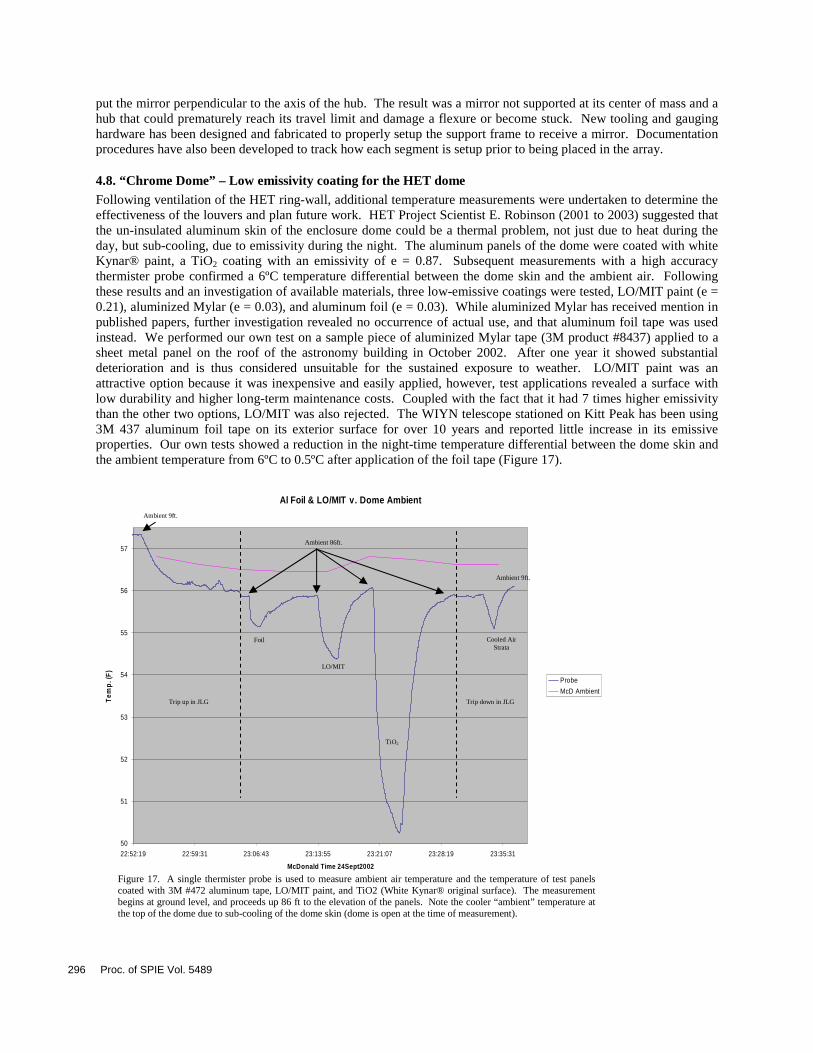
4.7. Segment Support Upgrade Each primary mirror segment is mounted on a steel frame (Figure 15) designed to support a segment radially through its center of mass by a flexure-mounted hub (Figure 16) and axially on three whiffletrees. The flexure permits the hub to move with the mirror as it is positioned in tip, tilt, and piston while maintaining radial support at the mirror’s center of mass. Tip, tilt, and piston of a segment are controlled by a stepper-motor driven actuator through a compound lever system that in a 19.2-nm resolution in the axial travel of the whiffletrees.
During primary mirror characterization, images of the primary revealed individual segments with poor images, leading to investigation of the segment support’s design and setup procedure. Mirrors with poor image quality were removed from the array and an “autopsy” was preformed on each mirror-frame assembly. Broken flexures in the hub assembly were a common failure, but there appeared to be at least two causes for the failures. One cause appeared to be metallurgical, the flexures were susceptible to hydrogen embrittlement when coated. A martensitic stainless steel was selected to replace the original 1075 steel, eliminating the need to coat the flexure for corrosion protection.
Another cause of flexure failure was a shearing action on the flexure when the mirror was moved axially beyond the travel limits of the flexure. This occurred routinely when an actuator was retracted during the homing process. Stops were designed and are being installed to limit the travel of the mirror when the actuators are homed. Software limits are used to limit travel as the actuator is extended.
The procedure used to setup a segment support frame prior to mounting a mirror had become a word-of-mouth procedure that had lost significant information through lack of documentation and personnel changeover. The setup procedure in place did not definitively position the mirror’s center of mass at the radial support position of hub or
Figure 16. Flexure-mounted hub providing radial support of individual mirror segments.
Figure 15. Primary mirror segment support frame.
Proc. of SPIE Vol. 5489 295
put the mirror perpendicular to the axis of the hub. The result was a mirror not supported at its center of mass and a hub that could prematurely reach its travel limit and damage a flexure or become stuck. New tooling and gauging hardware has been designed and fabricated to properly setup the support frame to receive a mirror. Documentation procedures have also been developed to track how each segment is setup prior to being placed in the array.
4.8. “Chrome Dome” – Low emissivity coating for the HET dome Following ventilation of the HET ring-wall, additional temperature measurements were undertaken to determine the effectiveness of the louvers and plan future work. HET Project Scientist E. Robinson (2001 to 2003) suggested that the un-insulated aluminum skin of the enclosure dome could be a thermal problem, not just due to heat during the day, but sub-cooling, due to emissivity during the night. The aluminum panels of the dome were coated with white Kynar® paint, a TiO2 coating with an emissivity of e = 0.87. Subsequent measurements with a high accuracy thermister probe confirmed a 6ºC temperature differential between the dome skin and the ambient air. Following these results and an investigation of available materials, three low-emissive coatings were tested, LO/MIT paint (e = 0.21), aluminized Mylar (e = 0.03), and aluminum foil (e = 0.03). While aluminized Mylar has received mention in published papers, further investigation revealed no occurrence of actual use, and that aluminum foil tape was used instead. We performed our own test on a sample piece of aluminized Mylar tape (3M product #8437) applied to a sheet metal panel on the roof of the astronomy building in October 2002. After one year it showed substantial deterioration and is thus considered unsuitable for the sustained exposure to weather. LO/MIT paint was an attractive option because it was inexpensive and easily applied, however, test applications revealed a surface with low durability and higher long-term maintenance costs. Coupled with the fact that it had 7 times higher emissivity than the other two options, LO/MIT was also rejected. The WIYN telescope stationed on Kitt Peak has been using 3M 437 aluminum foil tape on its exterior surface for over 10 years and reported little increase in its emissive properties. Our own tests showed a reduction in the night-time temperature differential between the dome skin and the ambient temperature from 6ºC to 0.5ºC after application of the foil tape (Figure 17).
Al Foil & LO/MIT v. Dome Ambient
50
51
52
53
54
55
56
57
22:52:19 22:59:31 23:06:43 23:13:55 23:21:07 23:28:19 23:35:31
McDonald Time 24Sept2002
Tem
p. (
F)
Probe
McD Ambient
Ambient 9ft.
Ambient 86ft.
Foil
LO/MIT
TiO2
Cooled Air Strata
Ambient 9ft.
Trip up in JLG Trip down in JLG
Figure 17. A single thermister probe is used to measure ambient air temperature and the temperature of test panels coated with 3M #472 aluminum tape, LO/MIT paint, and TiO2 (White Kynar® original surface). The measurement begins at ground level, and proceeds up 86 ft to the elevation of the panels. Note the cooler “ambient” temperature at the top of the dome due to sub-cooling of the dome skin (dome is open at the time of measurement).
296 Proc. of SPIE Vol. 5489
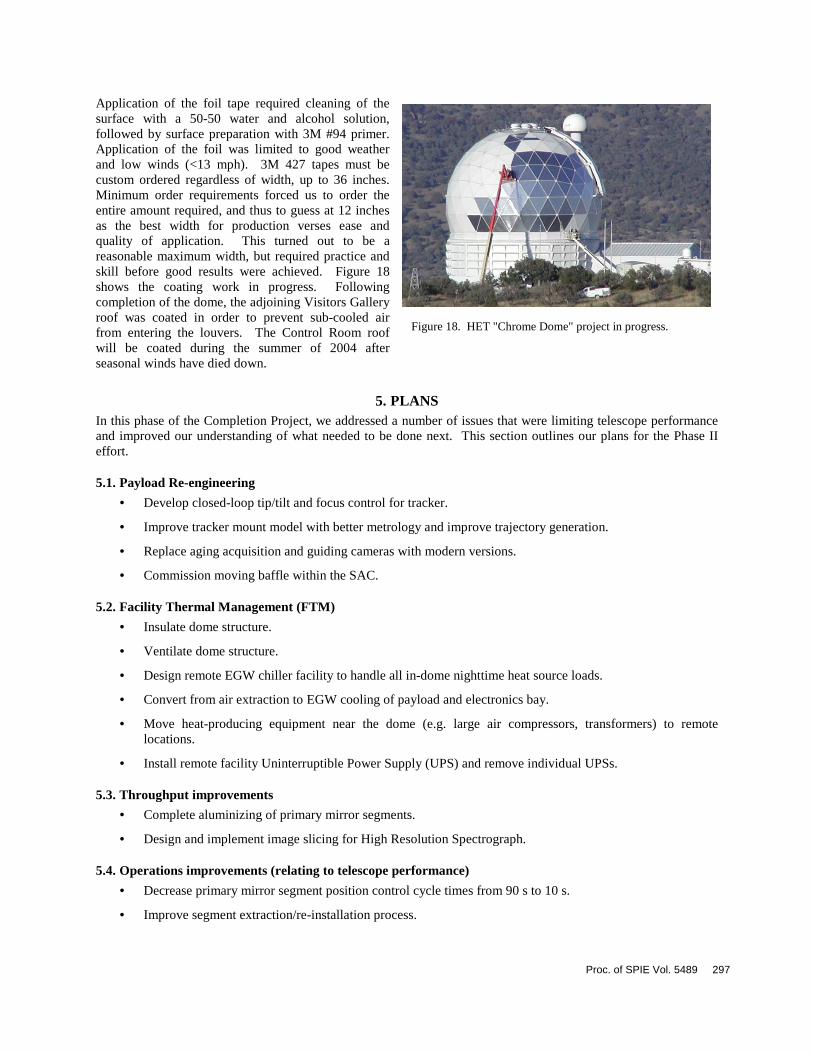
Application of the foil tape required cleaning of the surface with a 50-50 water and alcohol solution, followed by surface preparation with 3M #94 primer. Application of the foil was limited to good weather and low winds (<13 mph). 3M 427 tapes must be custom ordered regardless of width, up to 36 inches. Minimum order requirements forced us to order the entire amount required, and thus to guess at 12 inches as the best width for production verses ease and quality of application. This turned out to be a reasonable maximum width, but required practice and skill before good results were achieved. Figure 18 shows the coating work in progress. Following completion of the dome, the adjoining Visitors Gallery roof was coated in order to prevent sub-cooled air from entering the louvers. The Control Room roof will be coated during the summer of 2004 after seasonal winds have died down.
5. PLANS In this phase of the Completion Project, we addressed a number of issues that were limiting telescope performance and improved our understanding of what needed to be done next. This section outlines our plans for the Phase II effort.
5.1. Payload Re-engineering
• Develop closed-loop tip/tilt and focus control for tracker.
• Improve tracker mount model with better metrology and improve trajectory generation.
• Replace aging acquisition and guiding cameras with modern versions.
• Commission moving baffle within the SAC.
5.2. Facility Thermal Management (FTM)
• Insulate dome structure.
• Ventilate dome structure.
• Design remote EGW chiller facility to handle all in-dome nighttime heat source loads.
• Convert from air extraction to EGW cooling of payload and electronics bay.
• Move heat-producing equipment near the dome (e.g. large air compressors, transformers) to remote locations.
• Install remote facility Uninterruptible Power Supply (UPS) and remove individual UPSs.
5.3. Throughput improvements
• Complete aluminizing of primary mirror segments.
• Design and implement image slicing for High Resolution Spectrograph.
5.4. Operations improvements (relating to telescope performance)
• Decrease primary mirror segment position control cycle times from 90 s to 10 s.
• Improve segment extraction/re-installation process.
Figure 18. HET "Chrome Dome" project in progress.
Proc. of SPIE Vol. 5489 297
• Improve mirror segment cleaning and protection.
6. PROJECT COST The total cost of the HET through the end of 2003 was roughly $24M. The costs break down as follows:
• Initial construction cost, including use of accrued interest $14M
• Shakedown and commissioning $2M
• Instrumentation, consisting of the Low, Medium, and High Resolution Spectrographs $5M
• SAMS $1M
• Completion Project (DVS, MARS, many sub-projects) $2M
• Total $24M
These amounts include all materials, labor, and consulting fees, and represent the real “out-of-pocket” cost of the HET through 2003, excluding operations costs. Telescope operating costs are now about $1.6M/year.
7. SUMMARY We have completed a series of upgrades and modifications to the HET that have substantially improved the telescope’s delivered image quality and operational efficiency. Perhaps equally important has been the development of a clear understanding of what now limits telescope image quality and how to overcome these limitations. Hartmann testing and center of curvature testing in the Spring of 2003 confirmed that the primary mirror was performing adequately in all important respects. Additional on-sky testing demonstrated that SAC tip/tilt and focus errors dominated the delivered image quality.
Recoating of the primary mirror segment array was begun, and plans are in place to complete the array within the next 10 months. The SAC optics were recoated with a highly reflective and durable broadband coating at Lawrence Livermore National Laboratory. Mirror segment alignment and time lost due to problems have dropped by a factor of two from two years ago, to less than 10% and less than 6%, respectively. Low emissivity aluminum tape was applied to the telescope dome surface, drastically lowering the radiative cooling of the dome skin at night and reducing the temperature differential with ambient to 0.5°C or less. The software mount model that maintains optical alignment of the SAC with the 11-m primary mirror array was recalibrated and improved. The acquisition and guiding optics for both the High Resolution Spectrograph (HRS) and the Low Resolution Spectrograph (LRS) were reworked and improved, allowing for better focus and SAC alignment monitoring and control.
The edge sensor system (SAMS) was better calibrated with temperature and is now sufficiently stable that it routinely requires only one alignment at the beginning of the night. SAMS performance is expected to improve with the delivery of a complete spares inventory, expected this summer. Although telescope performance and efficiency have improved, more engineering upgrades are planned to consolidate these performance gains and to continue improving delivered image quality, throughput, and telescope operational efficiency.
8. ACKNOWLEDGMENTS A great many people have contributed to the success of the HET Completion Project thus far. While we will inevitably omit deserving persons in this acknowledgment, the authors would like to thank the following people for their assistance with this effort: HET Operations Day and Night staffs, often contributing in a development and engineering environment rather than an operations setting, McDonald Observatory Observing Support and Physical Plant, Dave Sanders and Jesse Wolfe of Lawrence Livermore National Laboratory, John Feind of Control & Equipment Company, El Paso, and Charles Corson, WIYN Site Engineer.
298 Proc. of SPIE Vol. 5489

9. REFERENCES 1 J.A. Booth, M.J. Wolf, J.R. Fowler, M.T. Adams, J.M. Good, P.W. Kelton, E.S. Barker, P. Palunas, F.N. Bash, L.W. Ramsey, G.J. Hill, P.J. MacQueen, M.E. Cornell, & E.L. Robinson, “The Hobby-Eberly Telescope Completion Project”, in Large Ground-Based Telescopes, Proc SPIE 4837, paper 109, 2002 2 L.W. Ramsey, M.T. Adams, T.G. Barnes, J.A. Booth, M.E. Cornell, J.R. Fowler, N.I. Gaffney, J.W. Glaspey, J. Good, P.W. Kelton, V.L. Krabbendam, L. Long, F.B. Ray, R.L. Ricklefs, J. Sage, T.A. Sebring, W.J. Spiesman, and M. Steiner, 1998, “The early performance and present status of the Hobby-Eberly Telescope,” S.P.I.E. Vol. 3352, Advanced Technology Optical/IR Telescope VI, p.34. 3 M. T. Adams, T. G. Barnes III, C. E. Nance and L. W. Ramsey, 2000, "Hobby-Eberly Telescope Operations Model", S.P.I.E. Vol. 4010, Observatory Operations To Optimize Scientific Return. 4 Hill, G.J., H. Nicklas, P.J. MacQueen, C. Tejada de V., F.J. Cobos D., and W. Mitsch, 1998, “The Hobby-Eberly Telescope Low Resolution Spectrograph,” S.P.I.E. Vol. 3355, p. 375. 5 G.J. Hill, P.J. MacQueen, C. Tejada de V., F.J. Cobos D., H. Nicklas, and W. Mitsch, 2000, "The Low Resolution Spectrograph of the Hobby-Eberly Telescope I. Description and Early Performance”, P.A.S.P. 6 R. G. Tull, 1998, "High-resolution fiber-coupled spectrograph of the Hobby-Eberly Telescope", S.P.I.E. Vol. 3355, Part One, Optical Astronomical Instrumentation, p. 387. 7 S. D. Horner, L. G. Engel, L. W. Ramsey, 1998, "Hobby Eberly Telescope medium-resolution spectrograph and fiber instrument feed", S.P.I.E. Vol. 3355, Part One, Optical Astronomical Instrumentation, p. 399. 8 T.G. Barnes III, M. T. Adams, J.A. Booth, M.E. Cornell, N. I. Gaffney, J .R. Fowler, G. J. Hill, C. E. Nance, L. W. Ramsey, R. L. Ricklefs, W. J. Spiesman, T. Worthington, 2000, "Commissioning Experience With The 9.2m Hobby Eberly Telescope", SPIE Vol. 4004, Telescope Structures, Enclosures, Controls, Assembly/Integration/Validation, and Commissioning. 9 J.W. Glaspey, M.T. Adams, J.A. Booth, M.E. Cornell, J.R. Fowler, V.I. Krabbendam, L.W. Ramsey, F.B. Ray, R.L. Ricklefs, and W.J. Spiesman, 1998, “Hobby-Eberly Telescope: commissioning experience and observing plans,” S.P.I.E. Vol. 3349, Observatory Operations to Optimize Scientific Return, p.50. 10 G. J. Hill, P. J. MacQueen, L. W. Ramsey and E. L. Robinson, 2000, "Early Science Results from the Hobby-Eberly Telescope", S.P.I.E. Vol. 4005, Discoveries and Research Prospects from 8 - 10 Meter Class Telescopes. 11 L. W. Ramsey et al., Early science and future prospects for the Hobby-Eberly telescope, SPIE vol. 4834, Discoveries and Research Prospects from 6 - 10 Meter Class Telescopes, 2002 12 P.J. MacQueen, “HET Aberations Due to the As-Built Surface Errors of M5”, private communication. 13 N. Thomas, J. Wolfe, “UV-Shifted Durable Silver Coating for Astronomical Mirrors”, Optical Design, materials, Fabrication, and Maintenance, SPIE Vol. 4003, p.312, 2000. 14 J.A. Booth, M.T. Adams, G.H. Ames, J.R. Fowler, E.E. Montgomery, J.M. Rakoczy, “Development of the segment alignment maintenance system (SAMS) for the Hobby-Eberly Telescope”, Proc. of SPIE, 4003, 176, 2000 15 M.T. Adams, P. Palunas, J.A. Booth, J.R. Fowler, M.J. Wolf, G.H. Ames, J.M. Rakoczy, E.E. Montgomery, “Hobby-Eberly Telescope Segment Alignment Maintenance System”, Proc. of SPIE, 4837, 693, 2003 16 J.M. Rakoczy, D Hall, W. Ly, R.T. Howard, E.E. Montgomery, M.T. Adams, J.A.Booth, J.R. Fowler, G.H. Ames, “Primary mirror figure maintenance of the Hobby-Eberly Telescope using the Segment Alignment Maintenance System”, Proc. of SPIE, 4837, 702, 2003 17 Nelson, J.E. & Mast, T.S. 1992, W.M. Keck Observatory Reports, Technical Report No 80 18 P. Palunas, J.R. Fowler, J.A. Booth, G. Damm, G. Ames 2004, “Control of the Hobby-Eberly Telescope primary mirror array with the segment alignment maintenance system,” Proc. of SPIE, 5496, paper 84 2004.
Proc. of SPIE Vol. 5489 299


![ANDREW B. ABEL AVINASH K. DIXIT JANICE C. EBERLY ROBERT …web.mit.edu/rpindyck/www/Papers/OptionsCapitalQJEAug06[1].pdf · AVINASH K. DIXIT JANICE C. EBERLY ROBERT S. PINDYCK](https://img.pdfslide.us/doc/110x75/5b279cbd7f8b9a68078b6669/andrew-b-abel-avinash-k-dixit-janice-c-eberly-robert-webmitedurpindyckwwwpapersoptionscapitalqjeaug061pdf.jpg)