Embed Size (px)
Citation preview
1
THE HISTORY OF YAMAHA TECHNOLOGY

THE HISTORY OFYAMAHA TECHNOLOGY
©2000 by Yamaha Motor Co., Ltd.
2nd Edition, November 2000
All rights reserved. Any reprinting or
unauthorized use without the written
permission of Yamaha Motor Co., Ltd.
is expressly prohibited.
Printed in Japan
2
DEVELOPMENTAL BACKGROUND
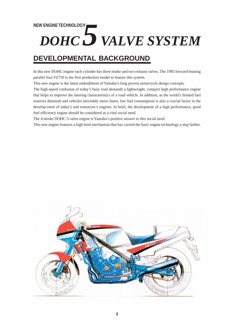
In this new DOHC engine each cylinder has three intake and two exhaust valves. The 1985 forward-leaning
parallel four FZ750 is the first production model to feature this system.
This new engine is the latest embodiment of Yamaha’s long proven motorcycle design concepts.
The high-speed confusion of today’s busy road demands a lightweight, compact high performance engine
that helps to improve the steering characteristics of a road vehicle. In addition, as the world’s limited fuel
reserves diminish and vehicles inevitably move faster, low fuel consumption is also a crucial factor in the
develop-ment of today’s and tomorrow’s engines. In brief, the development of a high performance, good
fuel efficiency engine should be considered as a vital social need.
The 4-stroke DOHC 5-valve engine is Yamaha’s positive answer to this social need.
This new engine features a high level mechanism that has carried the basic engine technology a step farther.
DOHC 5 VALVE SYSTEMNEW ENGINE TECHNOLOGY
3
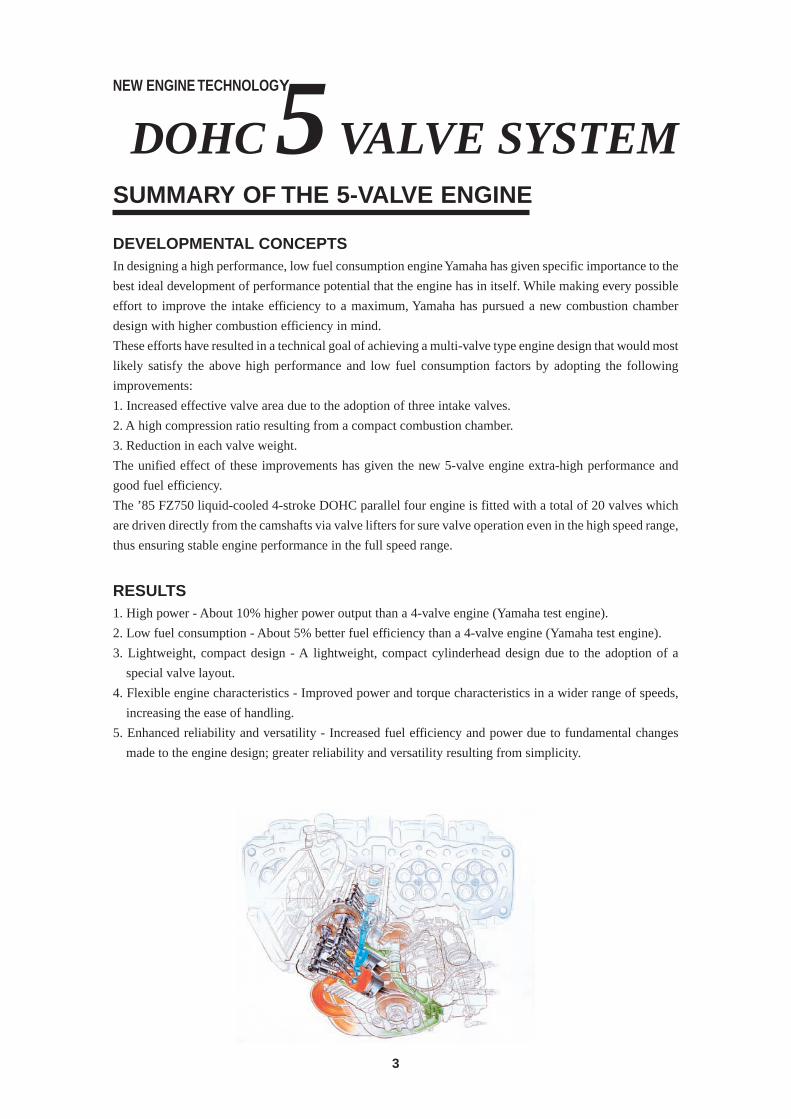
SUMMARY OF THE 5-VALVE ENGINE
DEVELOPMENTAL CONCEPTSIn designing a high performance, low fuel consumption engine Yamaha has given specific importance to the
best ideal development of performance potential that the engine has in itself. While making every possible
effort to improve the intake efficiency to a maximum, Yamaha has pursued a new combustion chamber
design with higher combustion efficiency in mind.
These efforts have resulted in a technical goal of achieving a multi-valve type engine design that would most
likely satisfy the above high performance and low fuel consumption factors by adopting the following
improvements:
1. Increased effective valve area due to the adoption of three intake valves.
2. A high compression ratio resulting from a compact combustion chamber.
3. Reduction in each valve weight.
The unified effect of these improvements has given the new 5-valve engine extra-high performance and
good fuel efficiency.
The ’85 FZ750 liquid-cooled 4-stroke DOHC parallel four engine is fitted with a total of 20 valves which
are driven directly from the camshafts via valve lifters for sure valve operation even in the high speed range,
thus ensuring stable engine performance in the full speed range.
RESULTS1. High power - About 10% higher power output than a 4-valve engine (Yamaha test engine).
2. Low fuel consumption - About 5% better fuel efficiency than a 4-valve engine (Yamaha test engine).
3. Lightweight, compact design - A lightweight, compact cylinderhead design due to the adoption of a
special valve layout.
4. Flexible engine characteristics - Improved power and torque characteristics in a wider range of speeds,
increasing the ease of handling.
5. Enhanced reliability and versatility - Increased fuel efficiency and power due to fundamental changes
made to the engine design; greater reliability and versatility resulting from simplicity.
DOHC 5 VALVE SYSTEMNEW ENGINE TECHNOLOGY
4
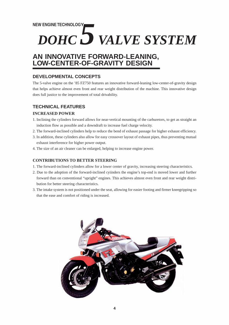
AN INNOVATIVE FORWARD-LEANING,LOW-CENTER-OF-GRAVITY DESIGN
DEVELOPMENTAL CONCEPTSThe 5-valve engine on the ’85 FZ750 features an innovative forward-leaning low-center-of-gravity design
that helps achieve almost even front and rear weight distribution of the machine. This innovative design
does full justice to the improvement of total drivability.
TECHNICAL FEATURESINCREASED POWER1. Inclining the cylinders forward allows for near-vertical mounting of the carburetors, to get as straight an
induction flow as possible and a downdraft to increase fuel charge velocity.
2. The forward-inclined cylinders help to reduce the bend of exhaust passage for higher exhaust efficiency.
3. In addition, these cylinders also allow for easy crossover layout of exhaust pipes, thus preventing mutual
exhaust interference for higher power output.
4. The size of an air cleaner can be enlarged, helping to increase engine power.
CONTRIBUTIONS TO BETTER STEERING1. The forward-inclined cylinders allow for a lower center of gravity, increasing steering characteristics.
2. Due to the adoption of the forward-inclined cyiinders the engine’s top-end is moved lower and further
forward than on conventional “upright” engines. This achieves almost even front and rear weight distri-
bution for better steering characteristics.
3. The intake system is not positioned under the seat, allowing for easier footing and firmer kneegripping so
that the ease and comfort of riding is increased.
DOHC 5 VALVE SYSTEMNEW ENGINE TECHNOLOGY
5
CONTENTS
FOREWORD ................................................................................................................................ 1
DEVELOPMENTAL BACKGROUND .......................................................................................... 2
SUMMARY OF THE 5-VALVE ENGINE ...................................................................................... 3
AN INNOVATIVE FORWARD-LEANING,LOW-CENTER-OF-GRAVITY DESIGN ..................... 4
1955—1960 THE ESTABLISHMENT OF “ORIGINALITY” ...................................................... 9
Yamaha motorcycles in the early stage of production ................................................................ 12
1955 Yamaha’s first production model YA-1 .......................................................... 13
1955 Primary kick starting system YA-1 .......................................................... 14
1956 Monoblock carburetor YC-1 ......................................................... 15
1957 2-stroke twin engine YD-1 ......................................................... 16
1957 Pressed steel plate frame (Moncoque) YA-2 .......................................................... 17
1958 Utility type model YD-2 ......................................................... 18
1959 Japan’s first pure-sports model YDS-1 ....................................................... 19
1959 Combination type instrument panel YDS-1 ....................................................... 20
1960 Tank-in-frame design MF-1 ......................................................... 21
1960 New type unit swing rear suspension MF-1 ......................................................... 21
1960 Fluid torque converter SC-1 ......................................................... 22
1961—1969 REVOLUTIONARY INNOVATIONS IN THE 2-STROKE FIELD ......................... 23
Yamaha motorcycles in the 60’s (Japan) ................................................................................... 26
1961 Rotary disc valve intake system YA-5 .......................................................... 27
1961 Water-and-dust resistant drum brake YA-5 .......................................................... 28
1963 Touring model YDT-1/YAT-1 ............................................. 29
1963 Ball lock type transmission YG-1 ......................................................... 30
1964 AutoIube YA-6/YG-1D .............................................. 31
1966 7-bone type pressed steel plate frame 90H3 ......................................................... 32
1967 Teflon coated oil seal 350R1 ....................................................... 32
1967 Labyrinth seal 350R1 ....................................................... 33
1967 Shift jump preventive device 350R1 ....................................................... 34
1967 5-port piston valve engine 125AS1-DX............................................... 35
1968 Pure-bred trail model 250DT1 ..................................................... 36
1968 Ceriani type front fork 250DT1 ..................................................... 37
1968 Trail pattern tire 250DT1 ..................................................... 38
1969 5-step adjustable rear shock absorber 125AT1 ..................................................... 39
1969 Audio pilot U5AD ........................................................ 40
1970—1974 BUILDING A QUALITY 2 & 4-STROKE LINE-UP .............................................. 41
1970 Yamaha’s first 4-stroke engine 650XS1 ..................................................... 44
1971 Reed valve intake mechanism HT90 ......................................................... 45
1971 7-port “Torque Induction” engine 175CT2 ..................................................... 46
1971 Manual decompressor RT360 ....................................................... 47
1971 Front disc brake XS650E .................................................... 48
1971 Omni-phase balancer device TX750 ....................................................... 49
1972 Blow-by gas recirculating device TX750 ....................................................... 50
1972 Aluminum rim TX750 ....................................................... 51
6
1972 Reserve lighting switch TX750 ....................................................... 51
1972 Connected righ & left exhaust pipes TX750 ....................................................... 51
1973 Automatic 2-speed transmission V50A/V70A ............................................... 52
1973 DOHC 8-valve engine TX500 ....................................................... 53
1973 IC voltage regulator TX500 ....................................................... 54
1973 Thermal flow shock absorber unit MX125 ...................................................... 55
1973 Yamaha’s first trials machine TY250J ..................................................... 56
1973 Monocross suspension YZ250 ....................................................... 57
1974 CDI system YZ250 ....................................................... 58
1975—1979 CONTINUED EFFORTS TO MEET DIVERSIFIED CUSTOMER NEEDS ........... 59
1975 Flasher self-canceeing system RD250/350 ............................................... 62
1975 Radial cooling fin DT400/250 ................................................ 63
1976 DOHC 3-cylinder engine GX750/XS750........................................... 64
1976 Shaft drive GX750/XS750........................................... 64
1976 Halogen headlamp GX750/XS750........................................... 65
1976 Flexible flasher mounting DT250 ....................................................... 65
1976 Front and rear disc brakes RD400/250 ............................................... 65
1976 4-stroke big single XT500 ....................................................... 66
1976 In-frame oil tank design XT500 ....................................................... 67
1977 Yamaha’s first parallel four XS Eleven ................................................. 68
1977 SU type 4-carb system XS Eleven ................................................. 69
1977 Oilbath type drive chain Passol S50 ............................................... 70
1977 High speed ignition-timing retarding system YZ250 ....................................................... 71
1978 Automatic choke Passola SA50 ........................................... 72
1978 “Special” styling XS650/750 Special ................................... 73
1978 Electronic ignition-timing advancing system XS650 Special .......................................... 74
1978 Transistor controlled ignition system XS650 Special .......................................... 75
1978 Brake lining wear indicator V50/V80 Series......................................... 76
1978 New automatic 2-speed transmission Passola SA50 ........................................... 77
1979 50cc shaft drive Carrot MA50 ............................................. 77
1979 Power jet carburetor TZ350 ....................................................... 78
1980—1984 LEADING THE AGE OF INTEGRATED TECHNOLOGY ................................... 79
1980 YPVS (Yamaha Power Valve System) TZ500 ....................................................... 82
1980 Zero cutawa carburetor TZ500 ....................................................... 83
1980 Liquid-cooled 2-storke engine YZ125 ....................................................... 84
1980 Calibmatic carburetor system Enduro 175 ............................................... 85
1980 Orthogonal engine mount RZ250/350, RD250/350............................ 86
1980 YEIS (Yamaha Energy Induction System) YZ250/IT200 ............................................. 87
1980 YICS (Yamaha Induction Control System) XJ400/550/650 ......................................... 88
1981 V-belt type stepless transmission CV50E/80E ............................................... 89
1981 100% alcohol engine RX125....................................................... 90
1981 In-line 75° V-twin engine XV750 Special .......................................... 91
1981 Frame integrated engine design XV750 Special .......................................... 92
1981 Anti-nosedive front fork XJ750A (XJ750 Seca) .............................. 93
1981 Computerized monitor system XJ750A (XJ750 Seca) .............................. 94
1982 Rising-rate Monocross suspension YZ490/250/125/100,IT175 ........................ 95
7
1982 Turbo system XJ650T ..................................................... 96
1982 Aerodynamics XJ650T ..................................................... 97
1982 YFIS (Yamaha Fuel Injection System) XJ750D ..................................................... 98
1982 Adjustable riding position XV920 Virago/XJ750 Maxim..................... 99
1982 Liquid-cooled V-twin YICS engine XZ400/550 .............................................. 100
1982 YDIS (Yamaha Duo Intake System) XT400/550 .............................................. 101
1982 DOHC twin with YICS XS400 Special ........................................ 102
1982 4-storke single with balancer XT125/200 .............................................. 103
1982 CYCOM (Cycle Communication) XV920 Virago/XJ750D/XJ650T .............. 104
1982 Hydraulic valve lifter XC180..................................................... 105
1983 New V-4 engine XVZ12T/XVZ12TD.................................. 106
1983 Computer Leveling Air Suspension System XVZ12TD ................................................ 107
(C.L.A.S.S.)
1984 Wide Lateral frame FJ1100 .................................................... 108
1984 Cruise control system XVZ12TD ................................................ 109
1984 2-stroke V-4 engine RZV500R/RD500LC ............................... 110
YAMAHA MOTORCYCLE TECHNICAL GUIDE .................................................................... 113
OHV Engine ............................................................................................................................. 114
One-piece Plated Cylinder and Crankcase .............................................................................. 115
Carbrized connecting rods ....................................................................................................... 116
Exhaust Ultimate Power Valve ................................................................................................. 117
Forged Aluminum Piston .......................................................................................................... 118
Traction Control System ........................................................................................................... 119
270-degree Crank Parallel Twin ............................................................................................... 120
Triple YPVS .............................................................................................................................. 121
YCLS ........................................................................................................................................ 122
5-Valve DOHC Engine ............................................................................................................. 123
Hair-pin Catalyzer .................................................................................................................... 124
Exhaust cleaning system for 2-stroke engines......................................................................... 125
3-Way Catalyser + Electronic-controlled Direct Fuel Injection System .................................... 126
Belt Drive System..................................................................................................................... 127
Deltabox ll Frame ..................................................................................................................... 128
ABS .......................................................................................................................................... 129
Truss Frame ............................................................................................................................. 130
YRACS ..................................................................................................................................... 131
Backrest Fitted Seat ................................................................................................................. 132
“Miracreate Finish” Fuel Tank ................................................................................................... 133
Aluminum Deltabox Frame....................................................................................................... 134

8

9
1955 - 1960
THE ESTABLISHMENTOF “ORIGINALITY”
10
COLOR HIGHLIGHT
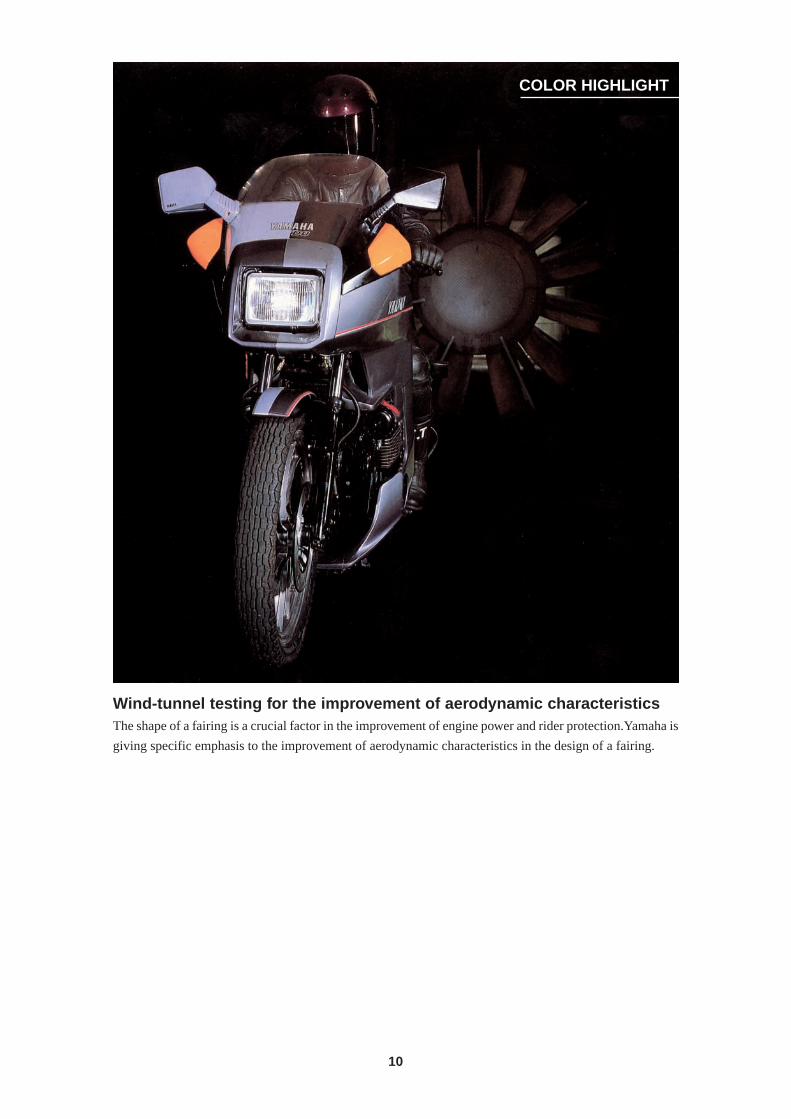
Wind-tunnel testing for the improvement of aerodynamic characteristicsThe shape of a fairing is a crucial factor in the improvement of engine power and rider protection.Yamaha is
giving specific emphasis to the improvement of aerodynamic characteristics in the design of a fairing.
11
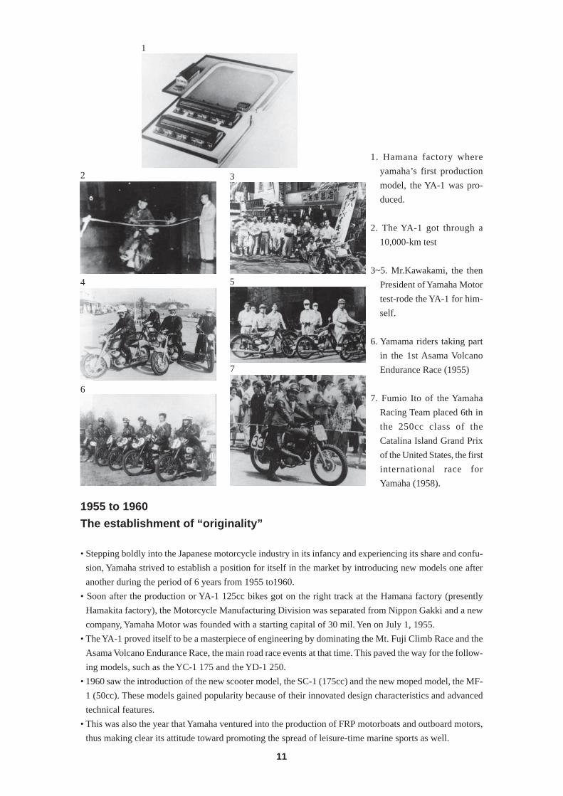
1. Hamana factory where
yamaha’s first production
model, the YA-1 was pro-
duced.
2. The YA-1 got through a
10,000-km test
3~5. Mr.Kawakami, the then
President of Yamaha Motor
test-rode the YA-1 for him-
self.
6. Yamama riders taking part
in the 1st Asama Volcano
Endurance Race (1955)
7. Fumio Ito of the Yamaha
Racing Team placed 6th in
the 250cc class of the
Catalina Island Grand Prix
of the United States, the first
international race for
Yamaha (1958).
1955 to 1960
The establishment of “originality”
• Stepping boldly into the Japanese motorcycle industry in its infancy and experiencing its share and confu-
sion, Yamaha strived to establish a position for itself in the market by introducing new models one after
another during the period of 6 years from 1955 to1960.
• Soon after the production or YA-1 125cc bikes got on the right track at the Hamana factory (presently
Hamakita factory), the Motorcycle Manufacturing Division was separated from Nippon Gakki and a new
company, Yamaha Motor was founded with a starting capital of 30 mil. Yen on July 1, 1955.
• The YA-1 proved itself to be a masterpiece of engineering by dominating the Mt. Fuji Climb Race and the
Asama Volcano Endurance Race, the main road race events at that time. This paved the way for the follow-
ing models, such as the YC-1 175 and the YD-1 250.
• 1960 saw the introduction of the new scooter model, the SC-1 (175cc) and the new moped model, the MF-
1 (50cc). These models gained popularity because of their innovated design characteristics and advanced
technical features.
• This was also the year that Yamaha ventured into the production of FRP motorboats and outboard motors,
thus making clear its attitude toward promoting the spread of leisure-time marine sports as well.
2
1
3
4 5
6
7
12
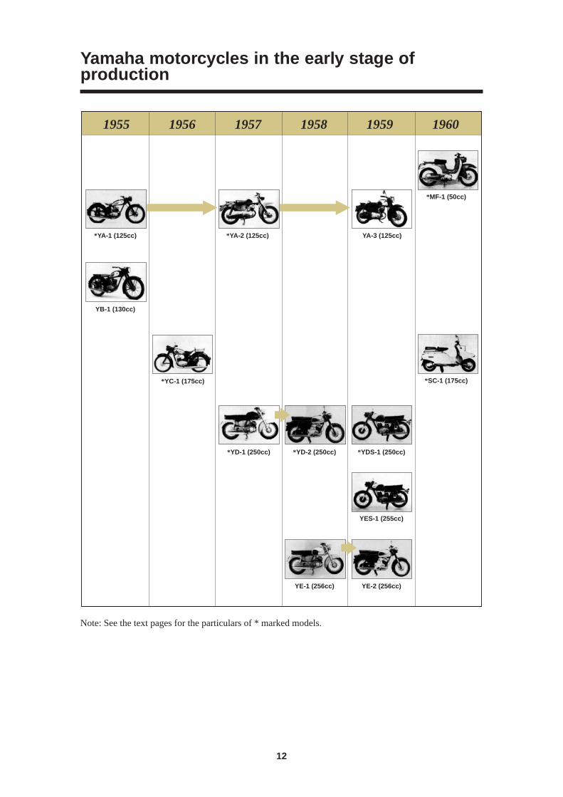
1955 1956 1957 1958 1959 1960
*YA-1 (125cc) *YA-2 (125cc) YA-3 (125cc)
*MF-1 (50cc)
*SC-1 (175cc)*YC-1 (175cc)
*YD-1 (250cc) *YD-2 (250cc)
YE-1 (256cc)
*YDS-1 (250cc)
YES-1 (255cc)
YE-2 (256cc)
YB-1 (130cc)
Yamaha motorcycles in the early stage ofproduction
Note: See the text pages for the particulars of * marked models.
13
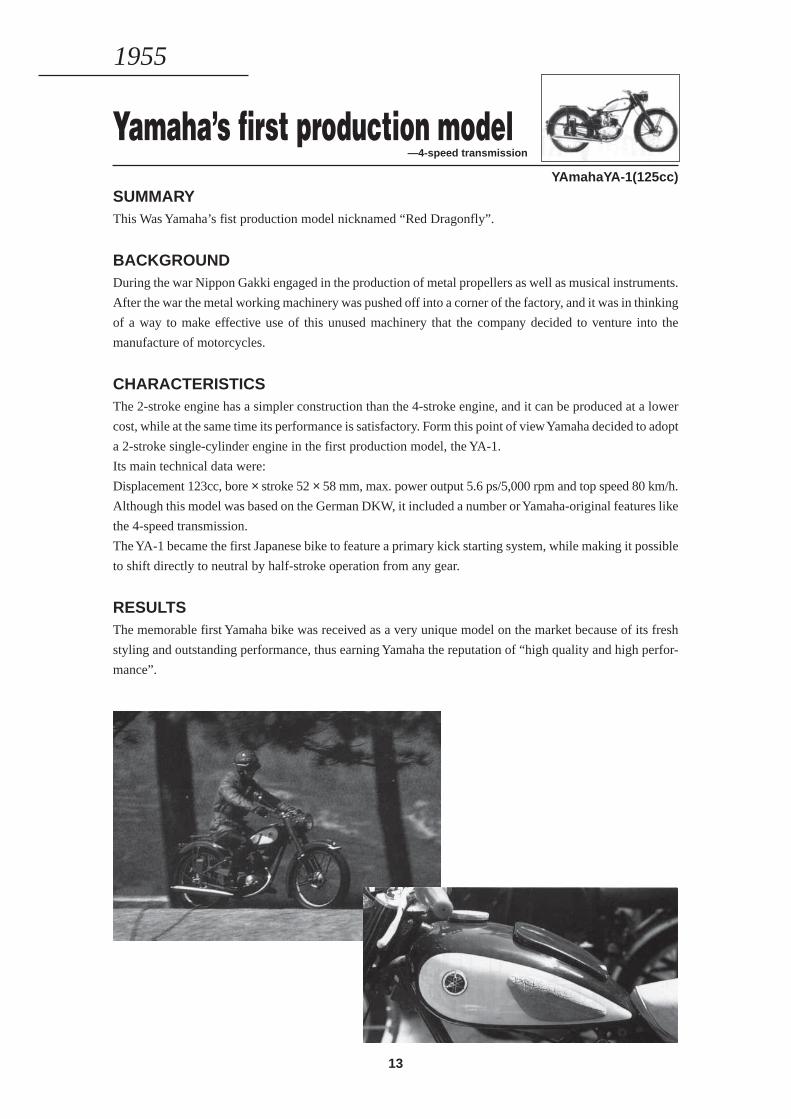
Yamaha’s first production model—4-speed transmission
YAmahaYA-1(125cc)
SUMMARYThis Was Yamaha’s fist production model nicknamed “Red Dragonfly”.
BACKGROUNDDuring the war Nippon Gakki engaged in the production of metal propellers as well as musical instruments.
After the war the metal working machinery was pushed off into a corner of the factory, and it was in thinking
of a way to make effective use of this unused machinery that the company decided to venture into the
manufacture of motorcycles.
CHARACTERISTICSThe 2-stroke engine has a simpler construction than the 4-stroke engine, and it can be produced at a lower
cost, while at the same time its performance is satisfactory. Form this point of view Yamaha decided to adopt
a 2-stroke single-cylinder engine in the first production model, the YA-1.
Its main technical data were:
Displacement 123cc, bore × stroke 52 × 58 mm, max. power output 5.6 ps/5,000 rpm and top speed 80 km/h.
Although this model was based on the German DKW, it included a number or Yamaha-original features like
the 4-speed transmission.
The YA-1 became the first Japanese bike to feature a primary kick starting system, while making it possible
to shift directly to neutral by half-stroke operation from any gear.
RESULTSThe memorable first Yamaha bike was received as a very unique model on the market because of its fresh
styling and outstanding performance, thus earning Yamaha the reputation of “high quality and high perfor-
mance”.
1955
14
Primary kick starting system —The first Japanese model of its kind
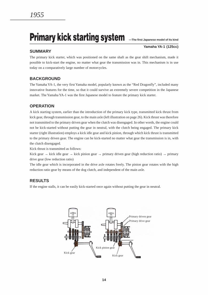
Yamaha YA-1 (125cc)SUMMARYThe primary kick starter, which was positioned on the same shaft as the gear shift mechanism, made it
possible to kick-start the engine, no matter what gear the transmission was in. This mechanism is in use
today on a comparatively large number of motorcycles.
BACKGROUNDThe Yamaha YA-1, the very first Yamaha model, popularly known as the “Red Dragonfly”, included many
innovative features for the time, so that it could survive an extremely severe competition in the Japanese
market. The Yamaha YA-1 was the first Japanese model to feature the primary kick starter.
OPERATIONA kick starting system, earlier than the introduction of the primary kick type, transmitted kick thrust from
kick gear, through transmission gear, to the main axle (left illustration on page 26). Kick thrust was therefore
not transmitted to the primary driven gear when the clutch was disengaged. In other words, the engine could
not be kick-started without putting the gear in neutral, with the clutch being engaged. The primary kick
starter (right illustration) employs a kick idle gear and kick pinion, through which kick thrust is transmitted
to the primary driven gear. The engine can be kick-started no matter what gear the transmission is in, with
the clutch disengaged.
Kick thrust is transmitted as follows:
Kick gear → kick idle gear → kick pinion gear → primary driven gear (high reduction ratio) → primary
drive gear (low reduction ratio)
The idle gear which is incorporated in the drive axle rotates freely. The pinion gear rotates with the high
reduction ratio gear by means of the dog clutch, and independent of the main axle.
RESULTSIf the engine stalls, it can be easily kick-started once again without putting the gear in neutral.
1955
Kick idle gear
Primary driven gear
Kick gear
Kick pinion gear
Kick gear
Primary drive gear

15
Monoblock carburetor —Shortened fuel passage
Yamaha YC-1 (175cc)
SUMMARYThe monoblock carburetor combined the mixing chamber and the float chamber in one body as a current
type does, which shortened the distance the fuel had to flow, thus improving the engine’s response and
boosting acceleration performance.
BACKGROUNDWhile other bikes at the time were using a standard type carburetor which had separate bodies for the mixing
chamber and the float chamber, the Yamaha YC-1 (175cc) which was introduced as the third production
model following the YA-1 (125cc) and the YB-l (130cc), was the first Japanese bike to employ the newly
designed monoblock type carburetor. In addition to this, the YC-1 was made even more distinctive by the
fact that the carburetor and its surrounding area was covered with an attractive streamlined cover.
CONSTRUCTIONA standard Amal type carburetor had separate bodies for the mixing chamber and float chamber which were
joined by means of a holding bolt. On the monoblock carburetor, the mixing chatnber and the float chamber
were cast in one block.
RESULTSThe gasoline passage was shortened, resulting in faster response to opening and closing of the throttle than
with a standard carburetor. This meant increased performance during acceleration. In addition, the float
chamber of the monoblock carburetor was directly above the mixing chamber in terms of the ventilation
passage. This meant the lean of the bike had no effect on the fuel surface in the float chamber, resulting in
stable carburetion.
1956
Standard Amal type carburetor Monoblock carburetor
16
2-stroke twin engine —Powerful and reliable
Yamaha YD-1 (250cc)
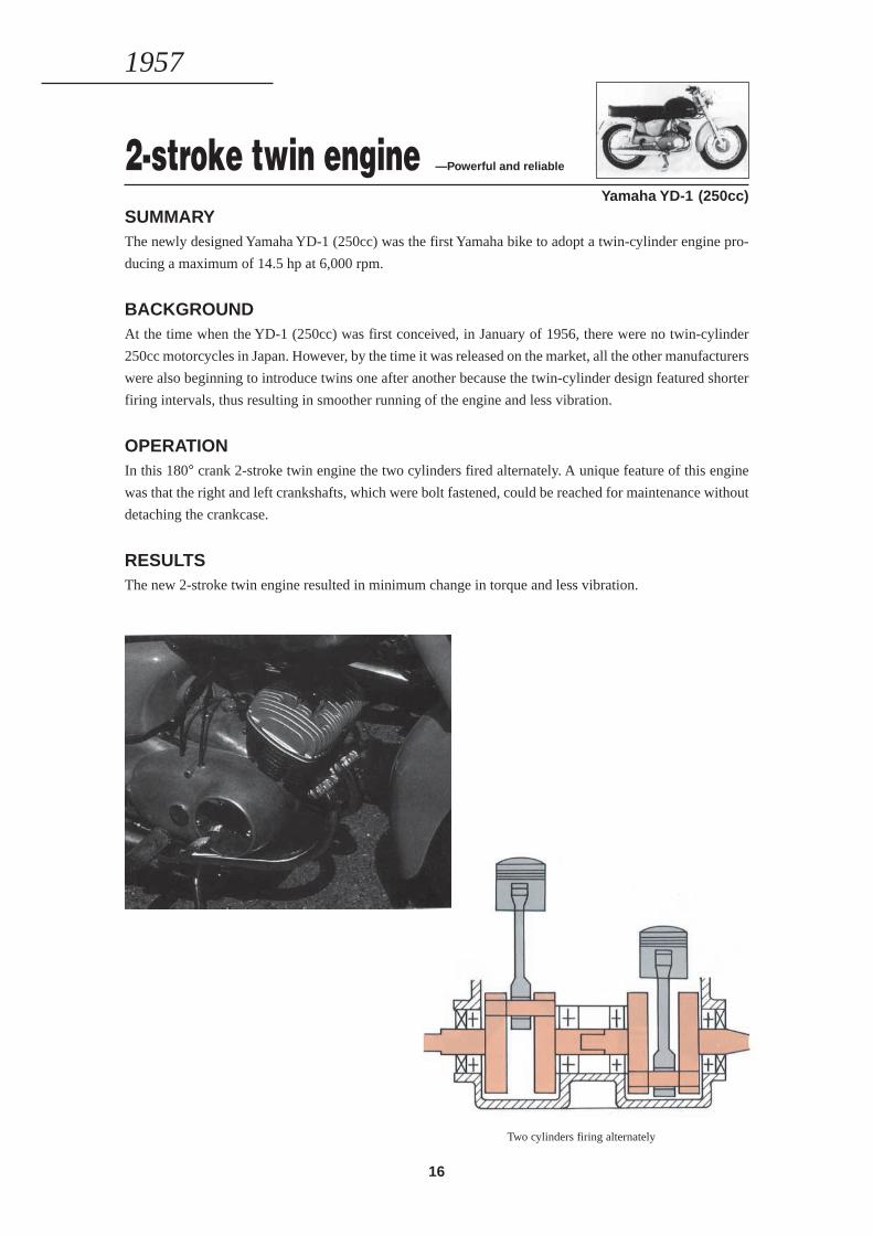
SUMMARYThe newly designed Yamaha YD-1 (250cc) was the first Yamaha bike to adopt a twin-cylinder engine pro-
ducing a maximum of 14.5 hp at 6,000 rpm.
BACKGROUNDAt the time when the YD-1 (250cc) was first conceived, in January of 1956, there were no twin-cylinder
250cc motorcycles in Japan. However, by the time it was released on the market, all the other manufacturers
were also beginning to introduce twins one after another because the twin-cylinder design featured shorter
firing intervals, thus resulting in smoother running of the engine and less vibration.
OPERATIONIn this 180° crank 2-stroke twin engine the two cylinders fired alternately. A unique feature of this engine
was that the right and left crankshafts, which were bolt fastened, could be reached for maintenance without
detaching the crankcase.
RESULTSThe new 2-stroke twin engine resulted in minimum change in torque and less vibration.
Two cylinders firing alternately
1957
17
Pressed steel plate frame(Monocoque) —G-mark awarded design
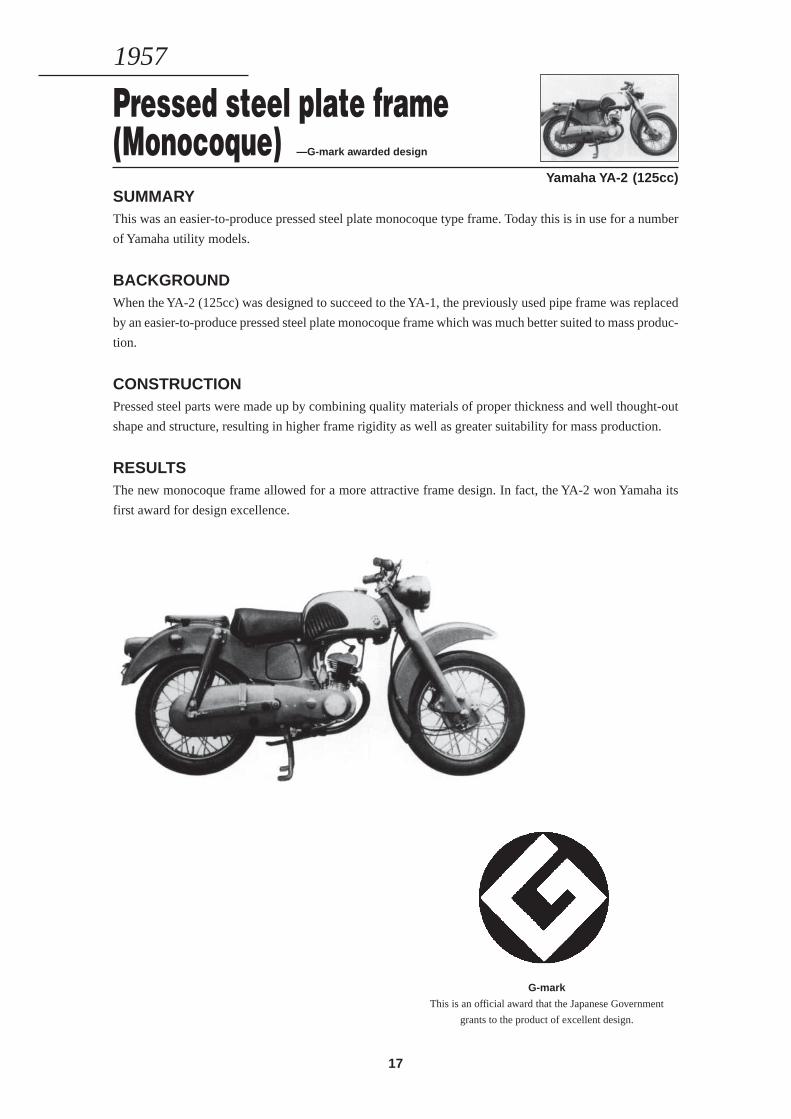
Yamaha YA-2 (125cc)SUMMARYThis was an easier-to-produce pressed steel plate monocoque type frame. Today this is in use for a number
of Yamaha utility models.
BACKGROUNDWhen the YA-2 (125cc) was designed to succeed to the YA-1, the previously used pipe frame was replaced
by an easier-to-produce pressed steel plate monocoque frame which was much better suited to mass produc-
tion.
CONSTRUCTIONPressed steel parts were made up by combining quality materials of proper thickness and well thought-out
shape and structure, resulting in higher frame rigidity as well as greater suitability for mass production.
RESULTSThe new monocoque frame allowed for a more attractive frame design. In fact, the YA-2 won Yamaha its
first award for design excellence.
G-mark
This is an official award that the Japanese Government
grants to the product of excellent design.
1957
18
Utility type model —Easier maintenance
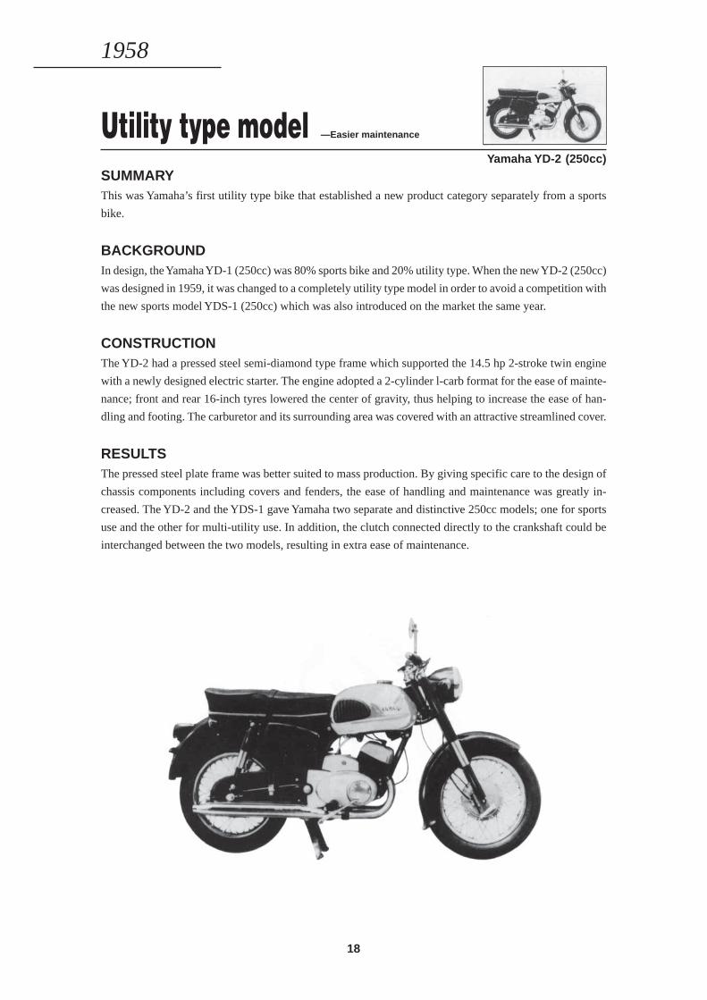
Yamaha YD-2 (250cc)SUMMARYThis was Yamaha’s first utility type bike that established a new product category separately from a sports
bike.
BACKGROUNDIn design, the Yamaha YD-1 (250cc) was 80% sports bike and 20% utility type. When the new YD-2 (250cc)
was designed in 1959, it was changed to a completely utility type model in order to avoid a competition with
the new sports model YDS-1 (250cc) which was also introduced on the market the same year.
CONSTRUCTIONThe YD-2 had a pressed steel semi-diamond type frame which supported the 14.5 hp 2-stroke twin engine
with a newly designed electric starter. The engine adopted a 2-cylinder l-carb format for the ease of mainte-
nance; front and rear 16-inch tyres lowered the center of gravity, thus helping to increase the ease of han-
dling and footing. The carburetor and its surrounding area was covered with an attractive streamlined cover.
RESULTSThe pressed steel plate frame was better suited to mass production. By giving specific care to the design of
chassis components including covers and fenders, the ease of handling and maintenance was greatly in-
creased. The YD-2 and the YDS-1 gave Yamaha two separate and distinctive 250cc models; one for sports
use and the other for multi-utility use. In addition, the clutch connected directly to the crankshaft could be
interchanged between the two models, resulting in extra ease of maintenance.
1958
19
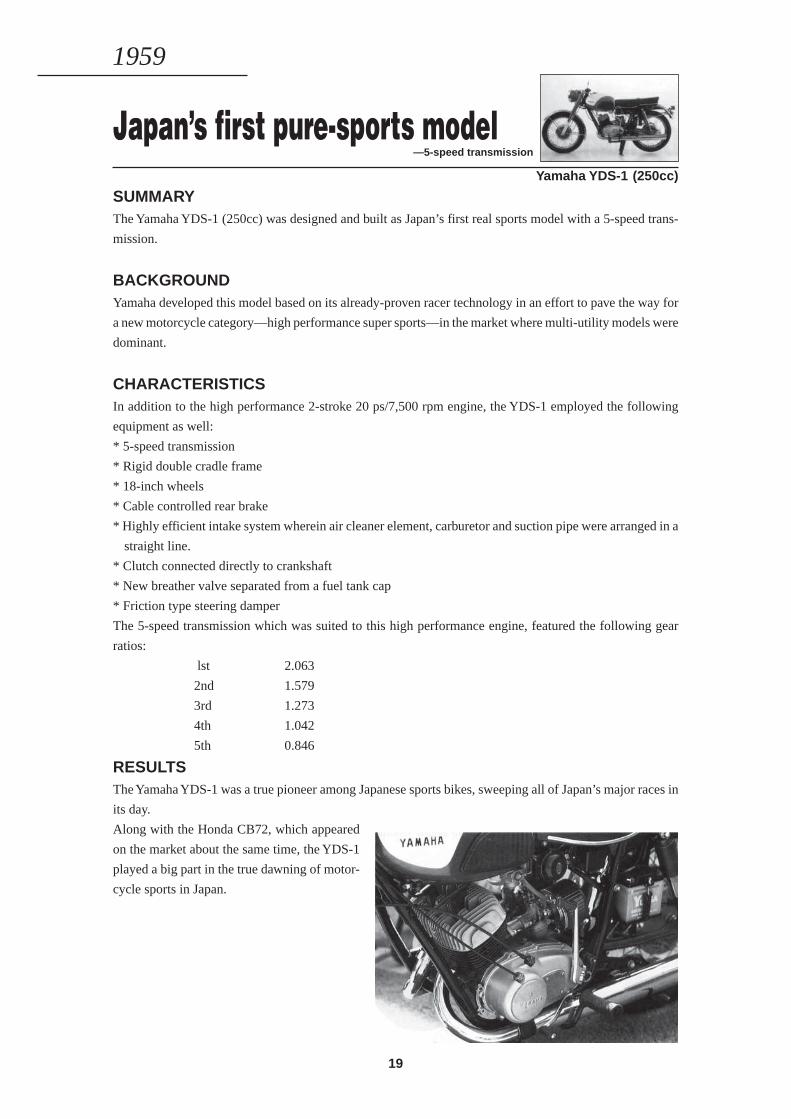
Japan’s first pure-sports model—5-speed transmission
Yamaha YDS-1 (250cc)
SUMMARYThe Yamaha YDS-1 (250cc) was designed and built as Japan’s first real sports model with a 5-speed trans-
mission.
BACKGROUNDYamaha developed this model based on its already-proven racer technology in an effort to pave the way for
a new motorcycle category—high performance super sports—in the market where multi-utility models were
dominant.
CHARACTERISTICSIn addition to the high performance 2-stroke 20 ps/7,500 rpm engine, the YDS-1 employed the following
equipment as well:
* 5-speed transmission
* Rigid double cradle frame
* 18-inch wheels
* Cable controlled rear brake
* Highly efficient intake system wherein air cleaner element, carburetor and suction pipe were arranged in a
straight line.
* Clutch connected directly to crankshaft
* New breather valve separated from a fuel tank cap
* Friction type steering damper
The 5-speed transmission which was suited to this high performance engine, featured the following gear
ratios:
lst 2.063
2nd 1.579
3rd 1.273
4th 1.042
5th 0.846
RESULTSThe Yamaha YDS-1 was a true pioneer among Japanese sports bikes, sweeping all of Japan’s major races in
its day.
Along with the Honda CB72, which appeared
on the market about the same time, the YDS-1
played a big part in the true dawning of motor-
cycle sports in Japan.
1959
20
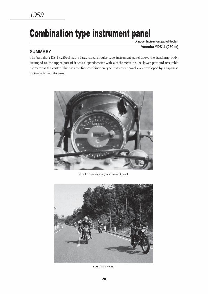
Combination type instrument panel—A novel instrument panel design
Yamaha YDS-1 (250cc)SUMMARYThe Yamaha YDS-1 (250cc) had a large-sized circular type instrument panel above the headlamp body.
Arranged on the upper part of it was a speedometer with a tachometer on the lower part and resettable
tripmeter at the center. This was the first combination type instrument panel ever developed by a Japanese
motorcycle manufacturer.
YDS-1’s combination type instrument panel
YDS Club meeting
1959
21
Tank-in-frame design —An innovative styling
Yamaha Moped MF-1 (50cc)SUMMARYA fuel tank was built in the end of pressed steel plate monocoque frame.
BACKGROUNDThis innovative frame design was developed to give the MF-1 an attractive moped styling quite unlike a
conventional motorcycle styling.
RESULTSThe suspension system was also newly designed along with the adoption of this innovative frame. The MF-1
was nice to look at, while it was easy to operate using the electric starter and centrifugal clutch type 3-speed
transmission.
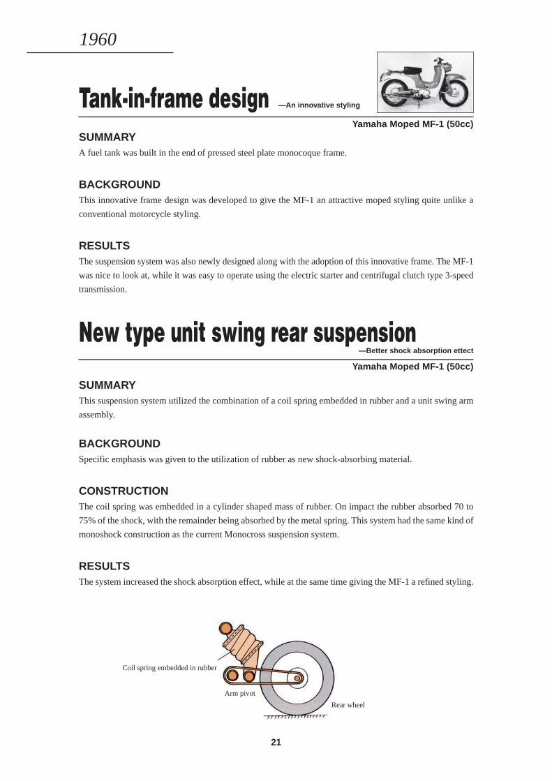
New type unit swing rear suspension—Better shock absorption ettect
Yamaha Moped MF-1 (50cc)
SUMMARYThis suspension system utilized the combination of a coil spring embedded in rubber and a unit swing arm
assembly.
BACKGROUNDSpecific emphasis was given to the utilization of rubber as new shock-absorbing material.
CONSTRUCTIONThe coil spring was embedded in a cylinder shaped mass of rubber. On impact the rubber absorbed 70 to
75% of the shock, with the remainder being absorbed by the metal spring. This system had the same kind of
monoshock construction as the current Monocross suspension system.
RESULTSThe system increased the shock absorption effect, while at the same time giving the MF-1 a refined styling.
Coil spring embedded in rubber
Arm pivot
Rear wheel
1960
22
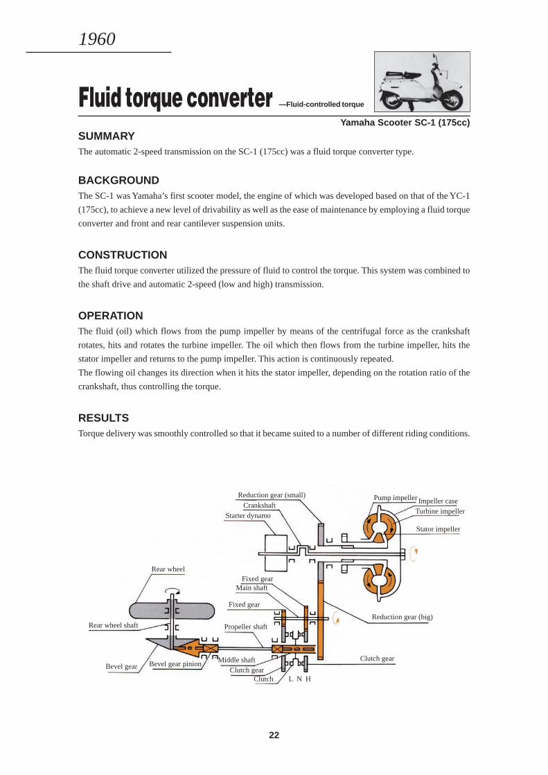
Fluid torque converter —Fluid-controlled torque
Yamaha Scooter SC-1 (175cc)
SUMMARYThe automatic 2-speed transmission on the SC-1 (175cc) was a fluid torque converter type.
BACKGROUNDThe SC-1 was Yamaha’s first scooter model, the engine of which was developed based on that of the YC-1
(175cc), to achieve a new level of drivability as well as the ease of maintenance by employing a fluid torque
converter and front and rear cantilever suspension units.
CONSTRUCTIONThe fluid torque converter utilized the pressure of fluid to control the torque. This system was combined to
the shaft drive and automatic 2-speed (low and high) transmission.
OPERATIONThe fluid (oil) which flows from the pump impeller by means of the centrifugal force as the crankshaft
rotates, hits and rotates the turbine impeller. The oil which then flows from the turbine impeller, hits the
stator impeller and returns to the pump impeller. This action is continuously repeated.
The flowing oil changes its direction when it hits the stator impeller, depending on the rotation ratio of the
crankshaft, thus controlling the torque.
RESULTSTorque delivery was smoothly controlled so that it became suited to a number of different riding conditions.
Rear wheel shaft
Rear wheel
Bevel gear Bevel gear pinion
Reduction gear (small)
CrankshaftStarter dynamo
Fixed gearMain shaft
Fixed gear
Propeller shaft
Middle shaftClutch gear
Pump impeller Impeller caseTurbine impeller
Stator impeller
Reduction gear (big)
Clutch gear
Clutch L N H
1960

23
1961—1969
REVOLUTIONARYINNOVATIONS
IN THE 2-STROKE FIELD
24
COLOR HIGHLIGHT
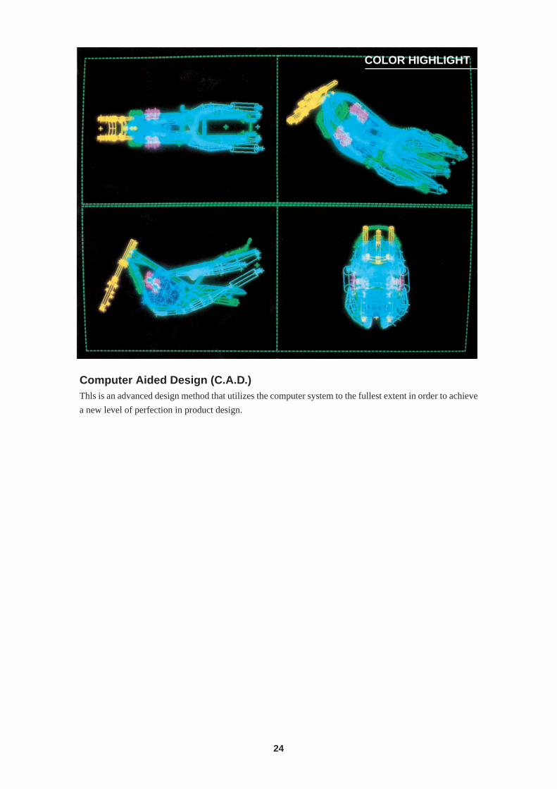
Computer Aided Design (C.A.D.)Thls is an advanced design method that utilizes the computer system to the fullest extent in order to achieve
a new level of perfection in product design.
25
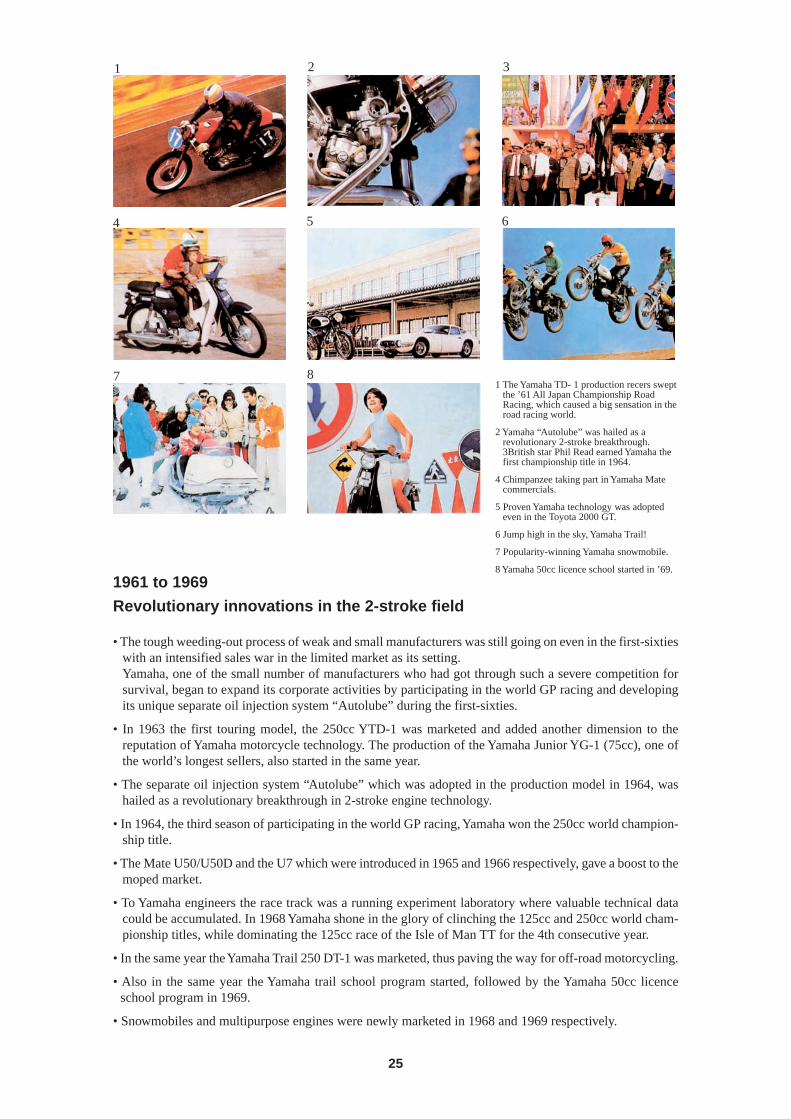
1 The Yamaha TD- 1 production recers sweptthe ’61 All Japan Championship RoadRacing, which caused a big sensation in theroad racing world.
2 Yamaha “Autolube” was hailed as arevolutionary 2-stroke breakthrough.3British star Phil Read earned Yamaha thefirst championship title in 1964.
4 Chimpanzee taking part in Yamaha Matecommercials.
5 Proven Yamaha technology was adoptedeven in the Toyota 2000 GT.
6 Jump high in the sky, Yamaha Trail!
7 Popularity-winning Yamaha snowmobile.
8 Yamaha 50cc licence school started in ’69.
1961 to 1969
Revolutionary innovations in the 2-stroke field
• The tough weeding-out process of weak and small manufacturers was still going on even in the first-sixtieswith an intensified sales war in the limited market as its setting.Yamaha, one of the small number of manufacturers who had got through such a severe competition forsurvival, began to expand its corporate activities by participating in the world GP racing and developingits unique separate oil injection system “Autolube” during the first-sixties.
• In 1963 the first touring model, the 250cc YTD-1 was marketed and added another dimension to thereputation of Yamaha motorcycle technology. The production of the Yamaha Junior YG-1 (75cc), one ofthe world’s longest sellers, also started in the same year.
• The separate oil injection system “Autolube” which was adopted in the production model in 1964, washailed as a revolutionary breakthrough in 2-stroke engine technology.
• In 1964, the third season of participating in the world GP racing, Yamaha won the 250cc world champion-ship title.
• The Mate U50/U50D and the U7 which were introduced in 1965 and 1966 respectively, gave a boost to themoped market.
• To Yamaha engineers the race track was a running experiment laboratory where valuable technical datacould be accumulated. In 1968 Yamaha shone in the glory of clinching the 125cc and 250cc world cham-pionship titles, while dominating the 125cc race of the Isle of Man TT for the 4th consecutive year.
• In the same year the Yamaha Trail 250 DT-1 was marketed, thus paving the way for off-road motorcycling.
• Also in the same year the Yamaha trail school program started, followed by the Yamaha 50cc licenceschool program in 1969.
• Snowmobiles and multipurpose engines were newly marketed in 1968 and 1969 respectively.
21 3
54 6
87
26
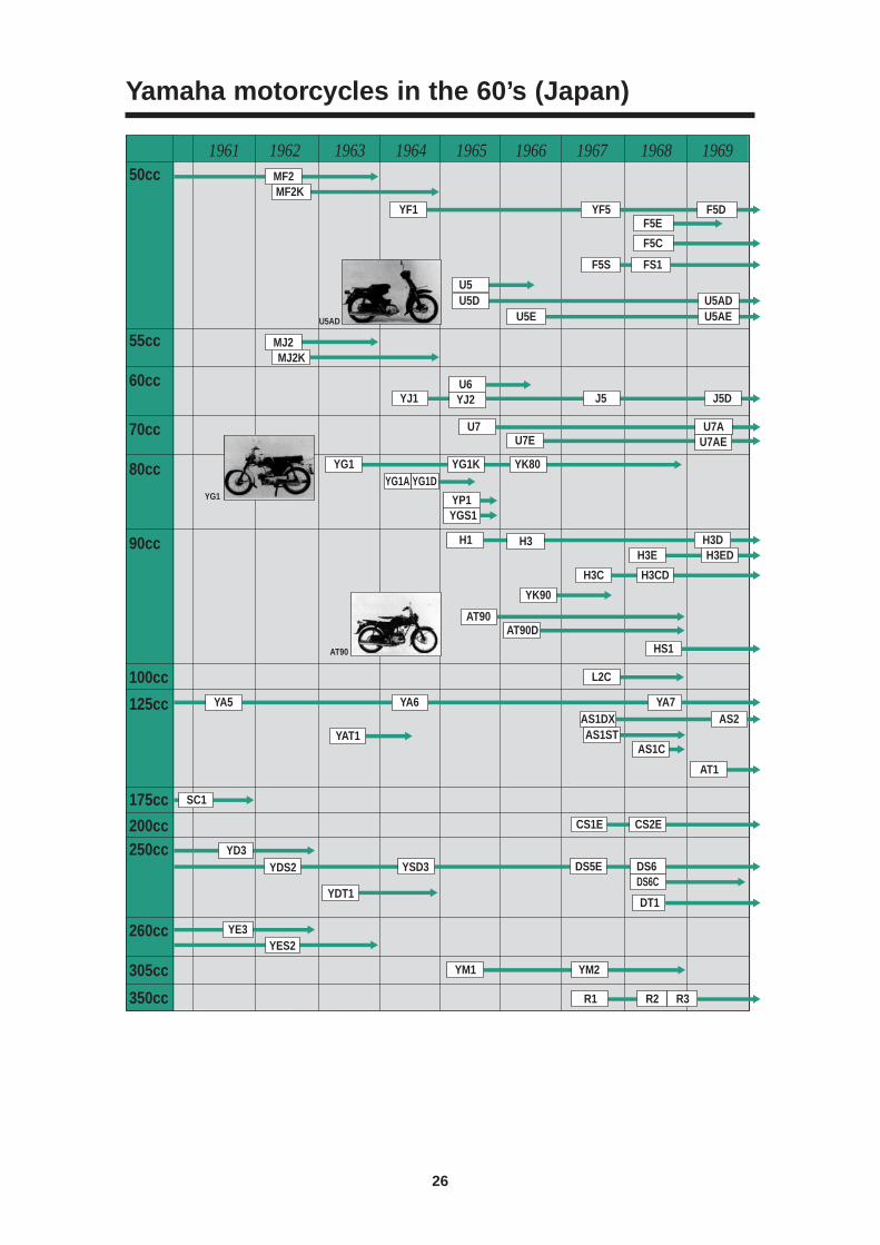
Yamaha motorcycles in the 60’s (Japan)
MF2MF2K
MJ2MJ2K
F5E
F5C
FS1
YF1
U5AD
YG1
AT90
YF5
F5S
F5D
U5ADU5DU5
U5AE
J5DJ5YJ1
U5E
U6
YG1A
YJ2
H3DH3EDH3E
H3C
YK90
YAT1
YDT1
YD3
SC1
YE3YES2
AS1STAS1C
AT1
CS1E CS2E
YM1 YM2
R1 R2 R3
YDS2 YSD3 DS5E
DT1
DS6DS6C
AT90AT90D
HS1
YA6YA5 YA7
L2C
H3CD
AS1DX AS2
H1 H3
YP1YGS1
U7AE
YK80YG1K
U7E
YG1
U7 U7A
YG1D
1961 1962 1963 1964 1965 1966 1967 1968 196950cc
55cc
60cc
70cc
80cc
90cc
100cc
125cc
175cc
200cc250cc
260cc
305cc
350cc
27
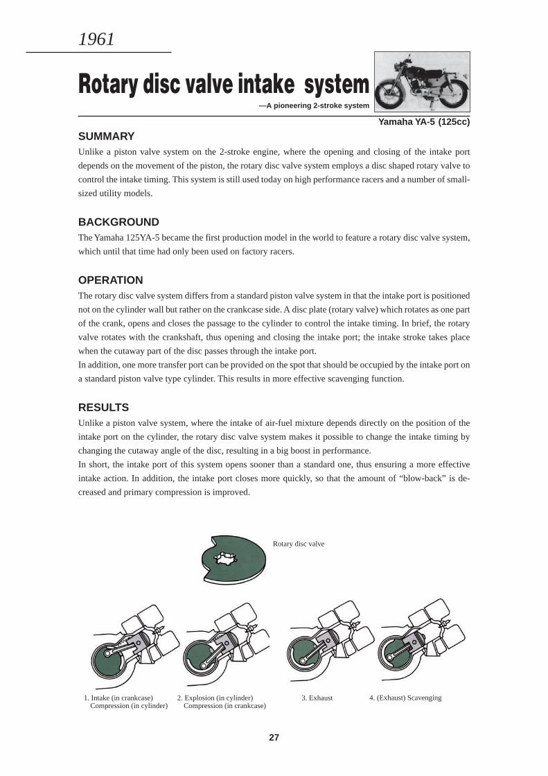
Rotary disc valve intake system —A pioneering 2-stroke system
Yamaha YA-5 (125cc)
SUMMARYUnlike a piston valve system on the 2-stroke engine, where the opening and closing of the intake port
depends on the movement of the piston, the rotary disc valve system employs a disc shaped rotary valve to
control the intake timing. This system is still used today on high performance racers and a number of small-
sized utility models.
BACKGROUNDThe Yamaha 125YA-5 became the first production model in the world to feature a rotary disc valve system,
which until that time had only been used on factory racers.
OPERATIONThe rotary disc valve system differs from a standard piston valve system in that the intake port is positioned
not on the cylinder wall but rather on the crankcase side. A disc plate (rotary valve) which rotates as one part
of the crank, opens and closes the passage to the cylinder to control the intake timing. In brief, the rotary
valve rotates with the crankshaft, thus opening and closing the intake port; the intake stroke takes place
when the cutaway part of the disc passes through the intake port.
In addition, one more transfer port can be provided on the spot that should be occupied by the intake port on
a standard piston valve type cylinder. This results in more effective scavenging function.
RESULTSUnlike a piston valve system, where the intake of air-fuel mixture depends directly on the position of the
intake port on the cylinder, the rotary disc valve system makes it possible to change the intake timing by
changing the cutaway angle of the disc, resulting in a big boost in performance.
In short, the intake port of this system opens sooner than a standard one, thus ensuring a more effective
intake action. In addition, the intake port closes more quickly, so that the amount of “blow-back” is de-
creased and primary compression is improved.
1. Intake (in crankcase)Compression (in cylinder)
Rotary disc valve
2. Explosion (in cylinder)Compression (in crankcase)
3. Exhaust 4. (Exhaust) Scavenging
1961
28
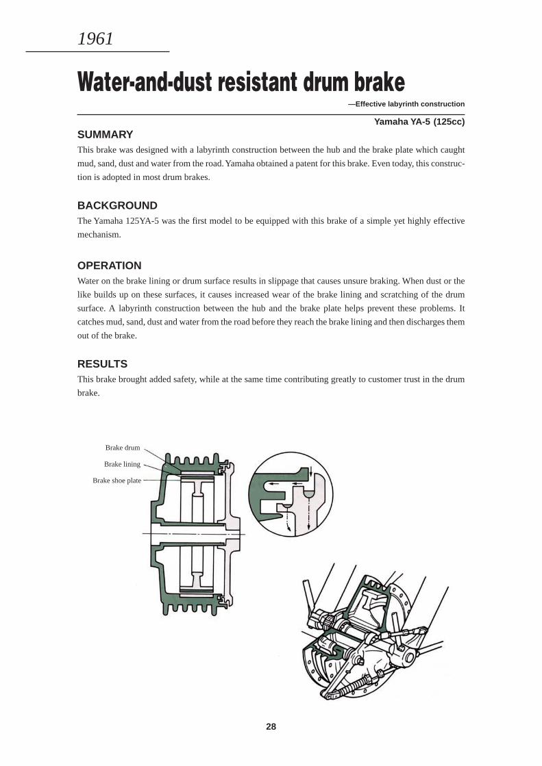
Water-and-dust resistant drum brake—Effective labyrinth construction
Yamaha YA-5 (125cc)SUMMARYThis brake was designed with a labyrinth construction between the hub and the brake plate which caught
mud, sand, dust and water from the road. Yamaha obtained a patent for this brake. Even today, this construc-
tion is adopted in most drum brakes.
BACKGROUNDThe Yamaha 125YA-5 was the first model to be equipped with this brake of a simple yet highly effective
mechanism.
OPERATIONWater on the brake lining or drum surface results in slippage that causes unsure braking. When dust or the
like builds up on these surfaces, it causes increased wear of the brake lining and scratching of the drum
surface. A labyrinth construction between the hub and the brake plate helps prevent these problems. It
catches mud, sand, dust and water from the road before they reach the brake lining and then discharges them
out of the brake.
RESULTSThis brake brought added safety, while at the same time contributing greatly to customer trust in the drum
brake.
Brake drum
Brake lining
Brake shoe plate
1961
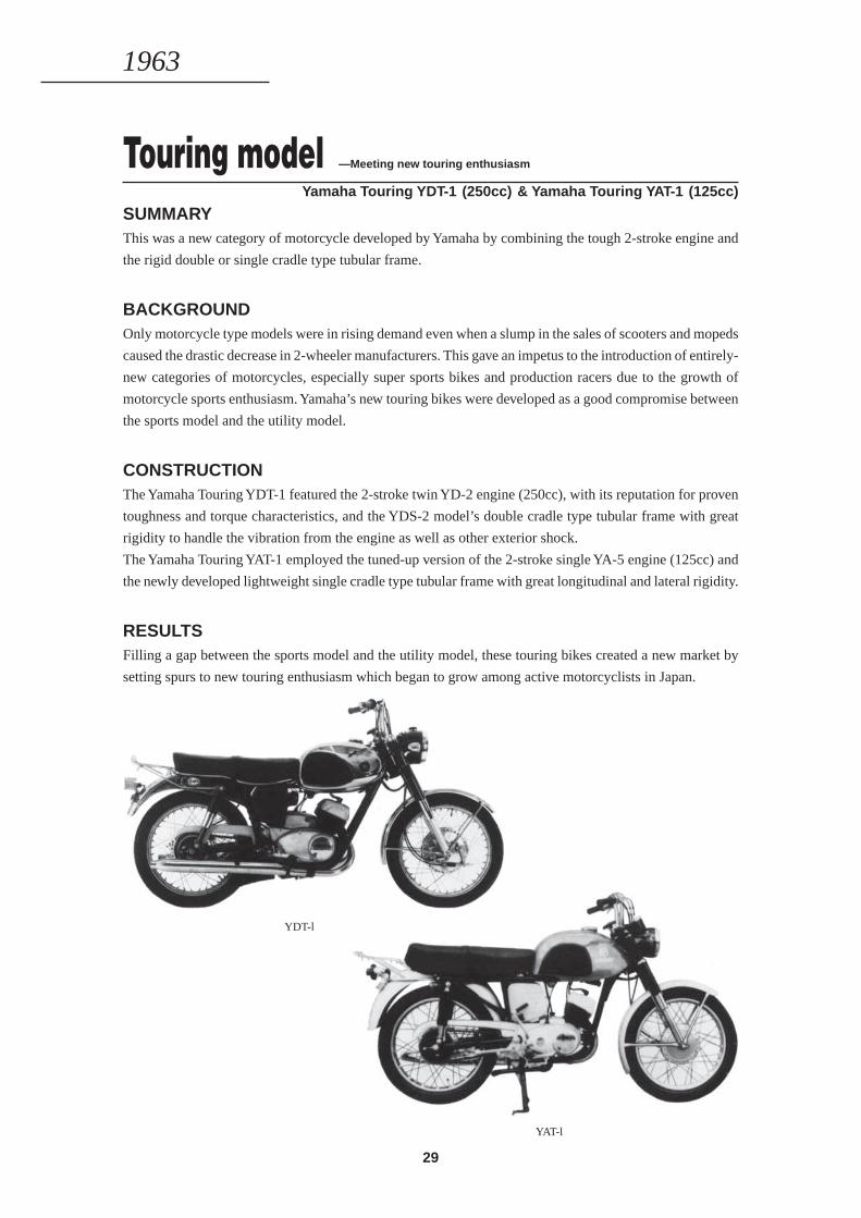
29
SUMMARYThis was a new category of motorcycle developed by Yamaha by combining the tough 2-stroke engine and
the rigid double or single cradle type tubular frame.
BACKGROUNDOnly motorcycle type models were in rising demand even when a slump in the sales of scooters and mopeds
caused the drastic decrease in 2-wheeler manufacturers. This gave an impetus to the introduction of entirely-
new categories of motorcycles, especially super sports bikes and production racers due to the growth of
motorcycle sports enthusiasm. Yamaha’s new touring bikes were developed as a good compromise between
the sports model and the utility model.
CONSTRUCTIONThe Yamaha Touring YDT-1 featured the 2-stroke twin YD-2 engine (250cc), with its reputation for proven
toughness and torque characteristics, and the YDS-2 model’s double cradle type tubular frame with great
rigidity to handle the vibration from the engine as well as other exterior shock.
The Yamaha Touring YAT-1 employed the tuned-up version of the 2-stroke single YA-5 engine (125cc) and
the newly developed lightweight single cradle type tubular frame with great longitudinal and lateral rigidity.
RESULTSFilling a gap between the sports model and the utility model, these touring bikes created a new market by
setting spurs to new touring enthusiasm which began to grow among active motorcyclists in Japan.
Touring model —Meeting new touring enthusiasm
Yamaha Touring YDT-1 (250cc) & Yamaha Touring YAT-1 (125cc)
YDT-l
YAT-l
1963
30
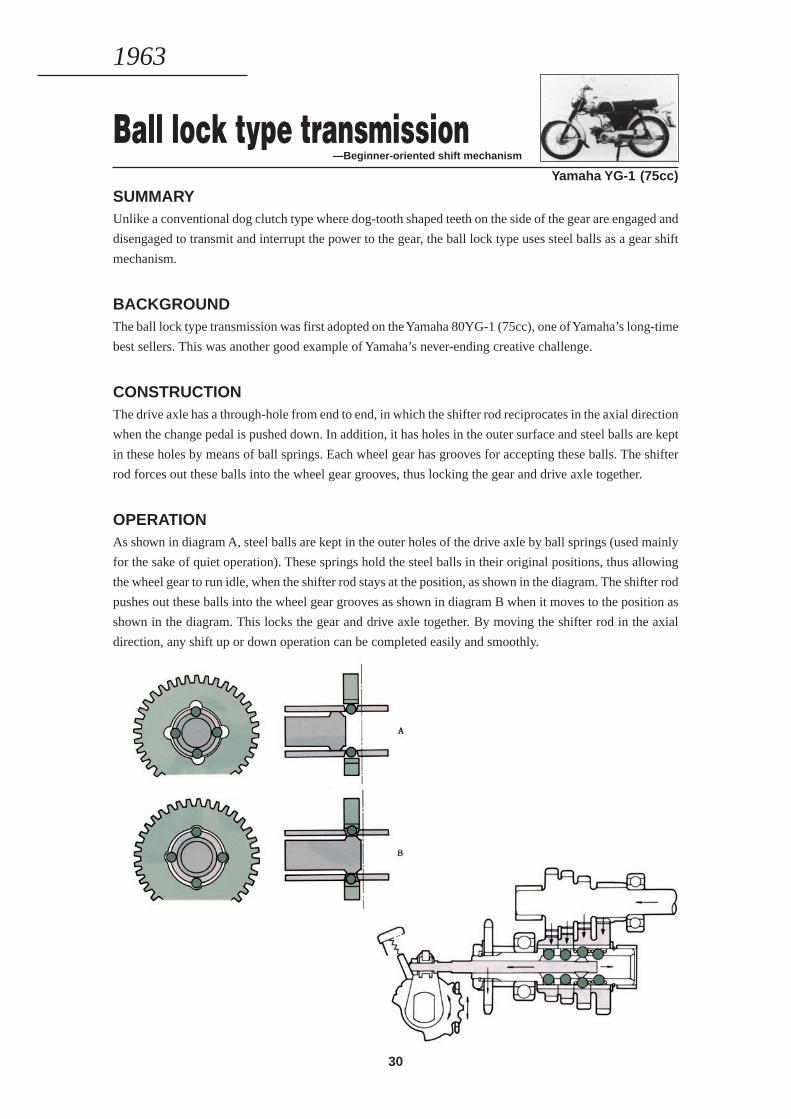
Ball lock type transmission—Beginner-oriented shift mechanism
Yamaha YG-1 (75cc)
SUMMARYUnlike a conventional dog clutch type where dog-tooth shaped teeth on the side of the gear are engaged and
disengaged to transmit and interrupt the power to the gear, the ball lock type uses steel balls as a gear shift
mechanism.
BACKGROUNDThe ball lock type transmission was first adopted on the Yamaha 80YG-1 (75cc), one of Yamaha’s long-time
best sellers. This was another good example of Yamaha’s never-ending creative challenge.
CONSTRUCTIONThe drive axle has a through-hole from end to end, in which the shifter rod reciprocates in the axial direction
when the change pedal is pushed down. In addition, it has holes in the outer surface and steel balls are kept
in these holes by means of ball springs. Each wheel gear has grooves for accepting these balls. The shifter
rod forces out these balls into the wheel gear grooves, thus locking the gear and drive axle together.
OPERATIONAs shown in diagram A, steel balls are kept in the outer holes of the drive axle by ball springs (used mainly
for the sake of quiet operation). These springs hold the steel balls in their original positions, thus allowing
the wheel gear to run idle, when the shifter rod stays at the position, as shown in the diagram. The shifter rod
pushes out these balls into the wheel gear grooves as shown in diagram B when it moves to the position as
shown in the diagram. This locks the gear and drive axle together. By moving the shifter rod in the axial
direction, any shift up or down operation can be completed easily and smoothly.
1963
31
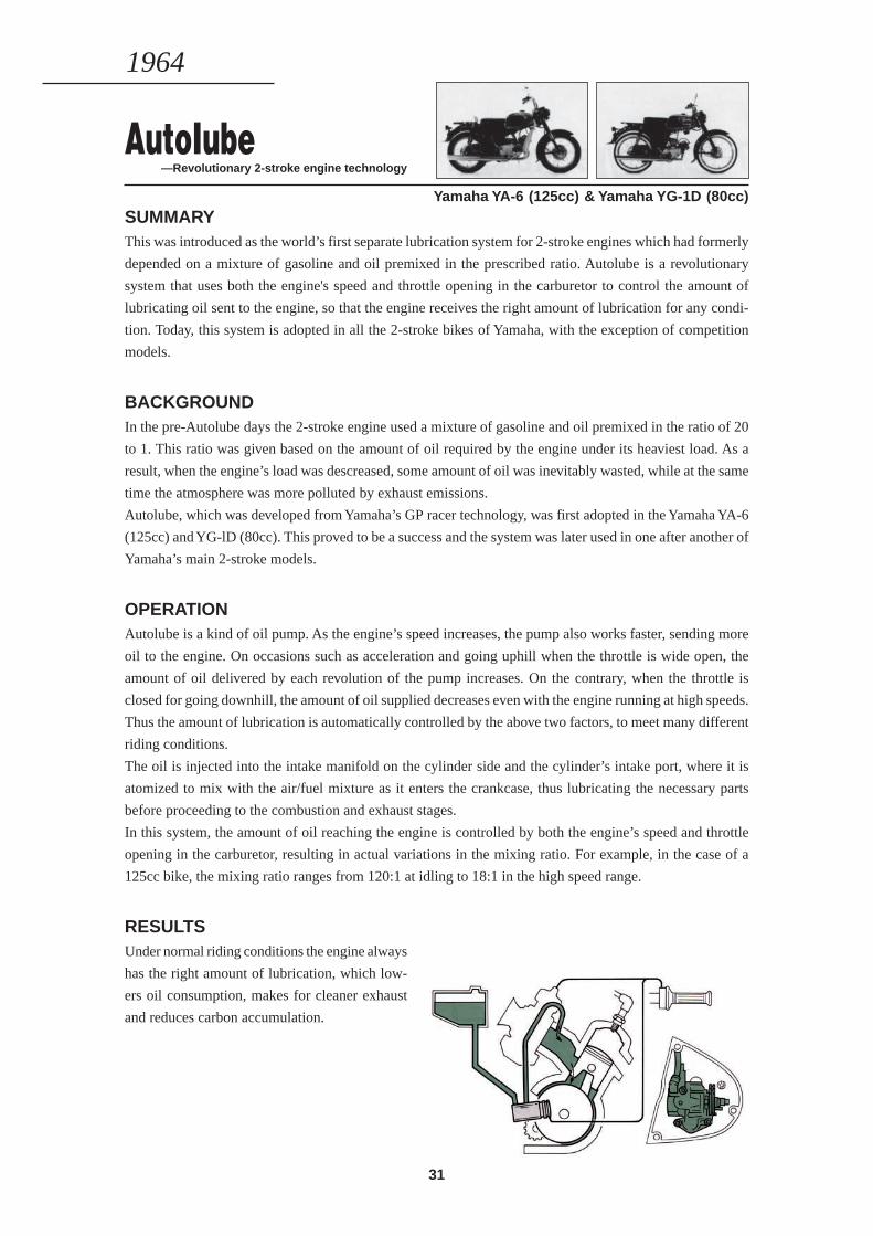
AutoIube—Revolutionary 2-stroke engine technology
Yamaha YA-6 (125cc) & Yamaha YG-1D (80cc)SUMMARYThis was introduced as the world’s first separate lubrication system for 2-stroke engines which had formerly
depended on a mixture of gasoline and oil premixed in the prescribed ratio. Autolube is a revolutionary
system that uses both the engine's speed and throttle opening in the carburetor to control the amount of
lubricating oil sent to the engine, so that the engine receives the right amount of lubrication for any condi-
tion. Today, this system is adopted in all the 2-stroke bikes of Yamaha, with the exception of competition
models.
BACKGROUNDIn the pre-Autolube days the 2-stroke engine used a mixture of gasoline and oil premixed in the ratio of 20
to 1. This ratio was given based on the amount of oil required by the engine under its heaviest load. As a
result, when the engine’s load was descreased, some amount of oil was inevitably wasted, while at the same
time the atmosphere was more polluted by exhaust emissions.
Autolube, which was developed from Yamaha’s GP racer technology, was first adopted in the Yamaha YA-6
(125cc) and YG-lD (80cc). This proved to be a success and the system was later used in one after another of
Yamaha’s main 2-stroke models.
OPERATIONAutolube is a kind of oil pump. As the engine’s speed increases, the pump also works faster, sending more
oil to the engine. On occasions such as acceleration and going uphill when the throttle is wide open, the
amount of oil delivered by each revolution of the pump increases. On the contrary, when the throttle is
closed for going downhill, the amount of oil supplied decreases even with the engine running at high speeds.
Thus the amount of lubrication is automatically controlled by the above two factors, to meet many different
riding conditions.
The oil is injected into the intake manifold on the cylinder side and the cylinder’s intake port, where it is
atomized to mix with the air/fuel mixture as it enters the crankcase, thus lubricating the necessary parts
before proceeding to the combustion and exhaust stages.
In this system, the amount of oil reaching the engine is controlled by both the engine’s speed and throttle
opening in the carburetor, resulting in actual variations in the mixing ratio. For example, in the case of a
125cc bike, the mixing ratio ranges from 120:1 at idling to 18:1 in the high speed range.
RESULTSUnder normal riding conditions the engine always
has the right amount of lubrication, which low-
ers oil consumption, makes for cleaner exhaust
and reduces carbon accumulation.
1964
32
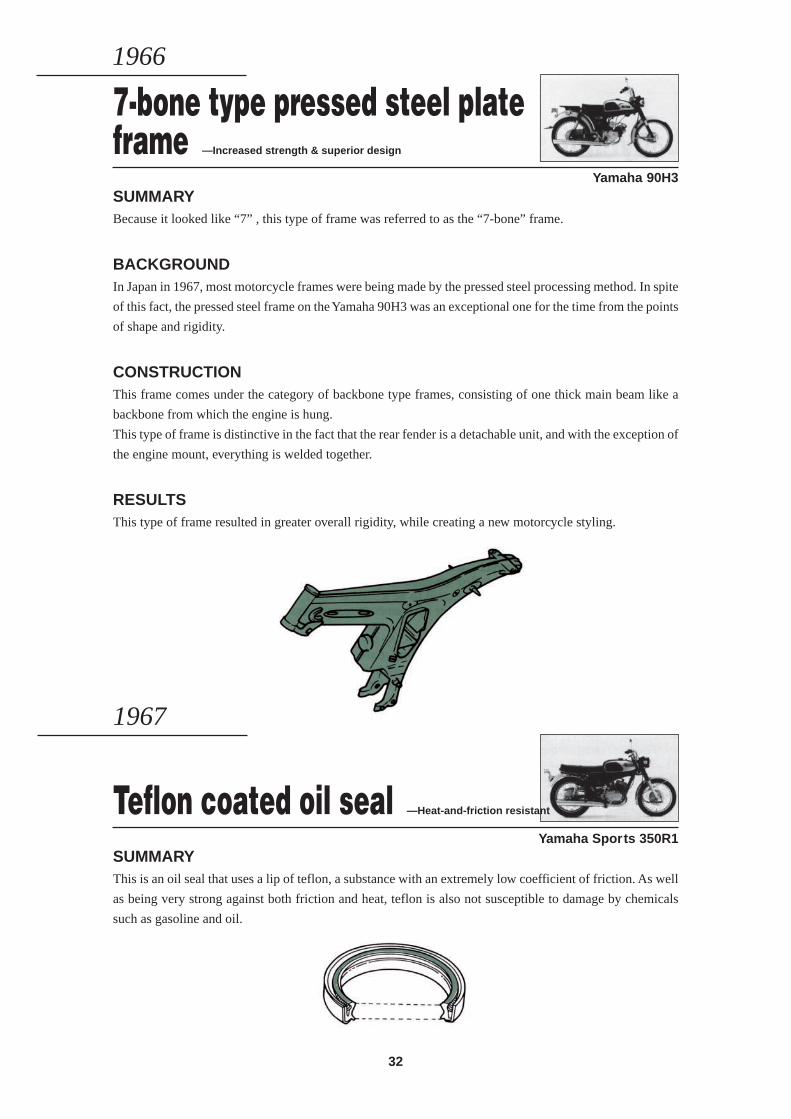
7-bone type pressed steel plateframe —Increased strength & superior design
Yamaha 90H3SUMMARYBecause it looked like “7” , this type of frame was referred to as the “7-bone” frame.
BACKGROUNDIn Japan in 1967, most motorcycle frames were being made by the pressed steel processing method. In spite
of this fact, the pressed steel frame on the Yamaha 90H3 was an exceptional one for the time from the points
of shape and rigidity.
CONSTRUCTIONThis frame comes under the category of backbone type frames, consisting of one thick main beam like a
backbone from which the engine is hung.
This type of frame is distinctive in the fact that the rear fender is a detachable unit, and with the exception of
the engine mount, everything is welded together.
RESULTSThis type of frame resulted in greater overall rigidity, while creating a new motorcycle styling.
1966
Teflon coated oil seal —Heat-and-friction resistant
Yamaha Sports 350R1SUMMARYThis is an oil seal that uses a lip of teflon, a substance with an extremely low coefficient of friction. As well
as being very strong against both friction and heat, teflon is also not susceptible to damage by chemicals
such as gasoline and oil.
1967
33
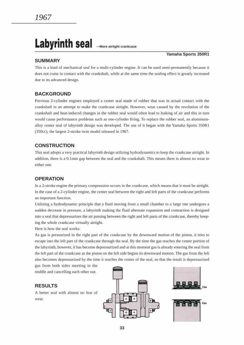
Labyrinth seal —More airtight crankcase
Yamaha Sports 350R1
SUMMARYThis is a kind of mechanical seal for a multi-cylinder engine. It can be used semi-permanently because it
does not come in contact with the crankshaft, while at the same time the sealing effect is greatly increased
due to its advanced design.
BACKGROUNDPrevious 2-cylinder engines employed a center seal made of rubber that was in actual contact with the
crankshaft in an attempt to make the crankcase airtight. However, wear caused by the revolution of the
crankshaft and heat-induced changes in the rubber seal would often lead to leaking of air and this in turn
would cause performance problems such as one-cylinder firing. To replace the rubber seal, an aluminum-
alloy center seal of labyrinth design was developed. The use of it began with the Yamaha Sports 350R1
(350cc), the largest 2-stroke twin model released in 1967.
CONSTRUCTIONThis seal adopts a very practical labyrinth design utilizing hydrodynamics to keep the crankcase airtight. In
addition, there is a 0.1mm gap between the seal and the crankshaft. This means there is almost no wear to
either one.
OPERATIONIn a 2-stroke engine the primary compression occurs in the crankcase, which means that it must be airtight.
In the case of a 2-cylinder engine, the center seal between the right and left parts of the crankcase performs
an important function.
Utilizing a hydrodynamic principle that a fluid moving from a small chamber to a large one undergoes a
sudden decrease in pressure, a labyrinth making the fluid alternate expansion and contraction is designed
into a seal that depressurizes the air passing between the right and left parts of the crankcase, thereby keep-
ing the whole crankcase virtually airtight.
Here is how the seal works:
As gas is pressurized in the right part of the crankcase by the downward motion of the piston, it tries to
escape into the left part of the crankcase through the seal. By the time the gas reaches the center portion of
the labyrinth, however, it has become depressurized and at this moment gas is already entering the seal from
the left part of the crankcase as the piston on the left side begins its downward motion. The gas from the left
also becomes depressurized by the time it reaches the center of the seal, so that the result is depressurized
gas from both sides meeting in the
middle and cancelling each other out.
RESULTSA better seal with almost no fear of
wear.
1967
34
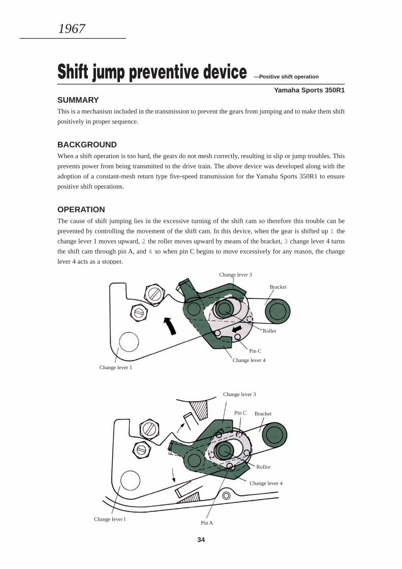
Shift jump preventive device —Positive shift operation
Yamaha Sports 350R1
SUMMARYThis is a mechanism included in the transmission to prevent the gears from jumping and to make them shift
positively in proper sequence.
BACKGROUNDWhen a shift operation is too hard, the gears do not mesh correctly, resulting in slip or jump troubles. This
prevents power from being transmitted to the drive train. The above device was developed along with the
adoption of a constant-mesh return type five-speed transmission for the Yamaha Sports 350R1 to ensure
positive shift operations.
OPERATIONThe cause of shift jumping lies in the excessive turning of the shift cam so therefore this trouble can be
prevented by controlling the movement of the shift cam. In this device, when the gear is shifted up 1 the
change lever 1 moves upward, 2 the roller moves upward by means of the bracket, 3 change lever 4 turns
the shift cam through pin A, and 4 so when pin C begins to move excessively for any reason, the change
lever 4 acts as a stopper.
1967
Change lever 1
Change lever 3
Bracket
Roller
Pin C
Change lever 4
Change lever l
Change lever 3
Pin C Bracket
RoIlor
Change lever 4
Pin A
35
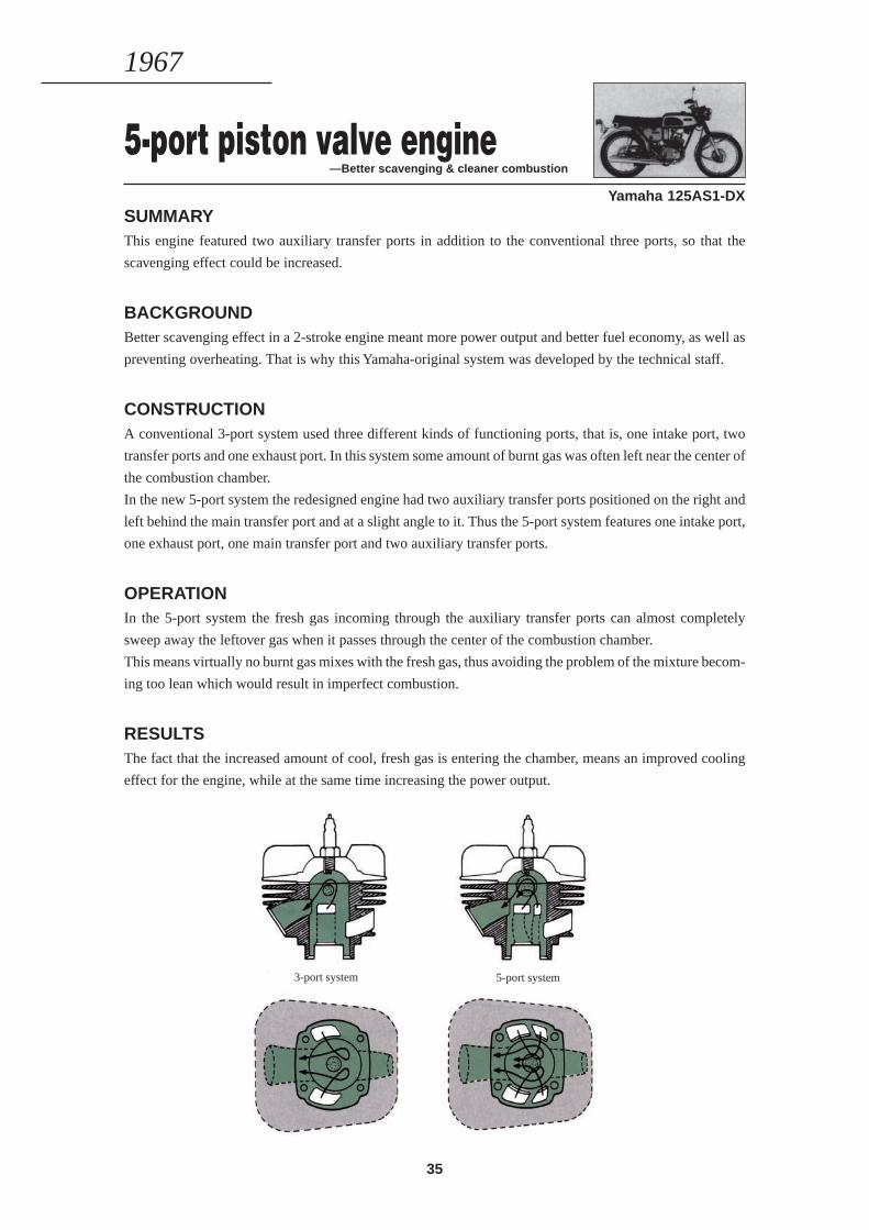
5-port piston valve engine—Better scavenging & cleaner combustion
Yamaha 125AS1-DXSUMMARYThis engine featured two auxiliary transfer ports in addition to the conventional three ports, so that the
scavenging effect could be increased.
BACKGROUNDBetter scavenging effect in a 2-stroke engine meant more power output and better fuel economy, as well as
preventing overheating. That is why this Yamaha-original system was developed by the technical staff.
CONSTRUCTIONA conventional 3-port system used three different kinds of functioning ports, that is, one intake port, two
transfer ports and one exhaust port. In this system some amount of burnt gas was often left near the center of
the combustion chamber.
In the new 5-port system the redesigned engine had two auxiliary transfer ports positioned on the right and
left behind the main transfer port and at a slight angle to it. Thus the 5-port system features one intake port,
one exhaust port, one main transfer port and two auxiliary transfer ports.
OPERATIONIn the 5-port system the fresh gas incoming through the auxiliary transfer ports can almost completely
sweep away the leftover gas when it passes through the center of the combustion chamber.
This means virtually no burnt gas mixes with the fresh gas, thus avoiding the problem of the mixture becom-
ing too lean which would result in imperfect combustion.
RESULTSThe fact that the increased amount of cool, fresh gas is entering the chamber, means an improved cooling
effect for the engine, while at the same time increasing the power output.
1967
3-port system 5-port system
36
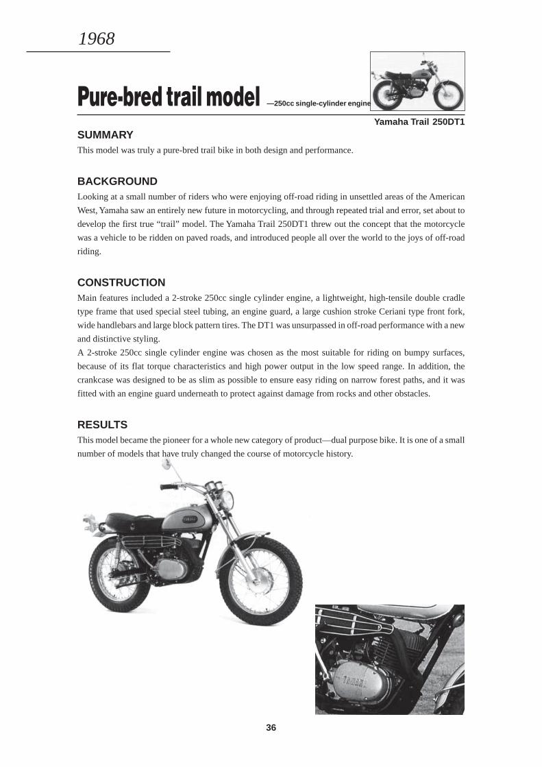
Pure-bred trail model —250cc single-cylinder engine
Yamaha Trail 250DT1
SUMMARYThis model was truly a pure-bred trail bike in both design and performance.
BACKGROUNDLooking at a small number of riders who were enjoying off-road riding in unsettled areas of the American
West, Yamaha saw an entirely new future in motorcycling, and through repeated trial and error, set about to
develop the first true “trail” model. The Yamaha Trail 250DT1 threw out the concept that the motorcycle
was a vehicle to be ridden on paved roads, and introduced people all over the world to the joys of off-road
riding.
CONSTRUCTIONMain features included a 2-stroke 250cc single cylinder engine, a lightweight, high-tensile double cradle
type frame that used special steel tubing, an engine guard, a large cushion stroke Ceriani type front fork,
wide handlebars and large block pattern tires. The DT1 was unsurpassed in off-road performance with a new
and distinctive styling.
A 2-stroke 250cc single cylinder engine was chosen as the most suitable for riding on bumpy surfaces,
because of its flat torque characteristics and high power output in the low speed range. In addition, the
crankcase was designed to be as slim as possible to ensure easy riding on narrow forest paths, and it was
fitted with an engine guard underneath to protect against damage from rocks and other obstacles.
RESULTSThis model became the pioneer for a whole new category of product—dual purpose bike. It is one of a small
number of models that have truly changed the course of motorcycle history.
1968
37
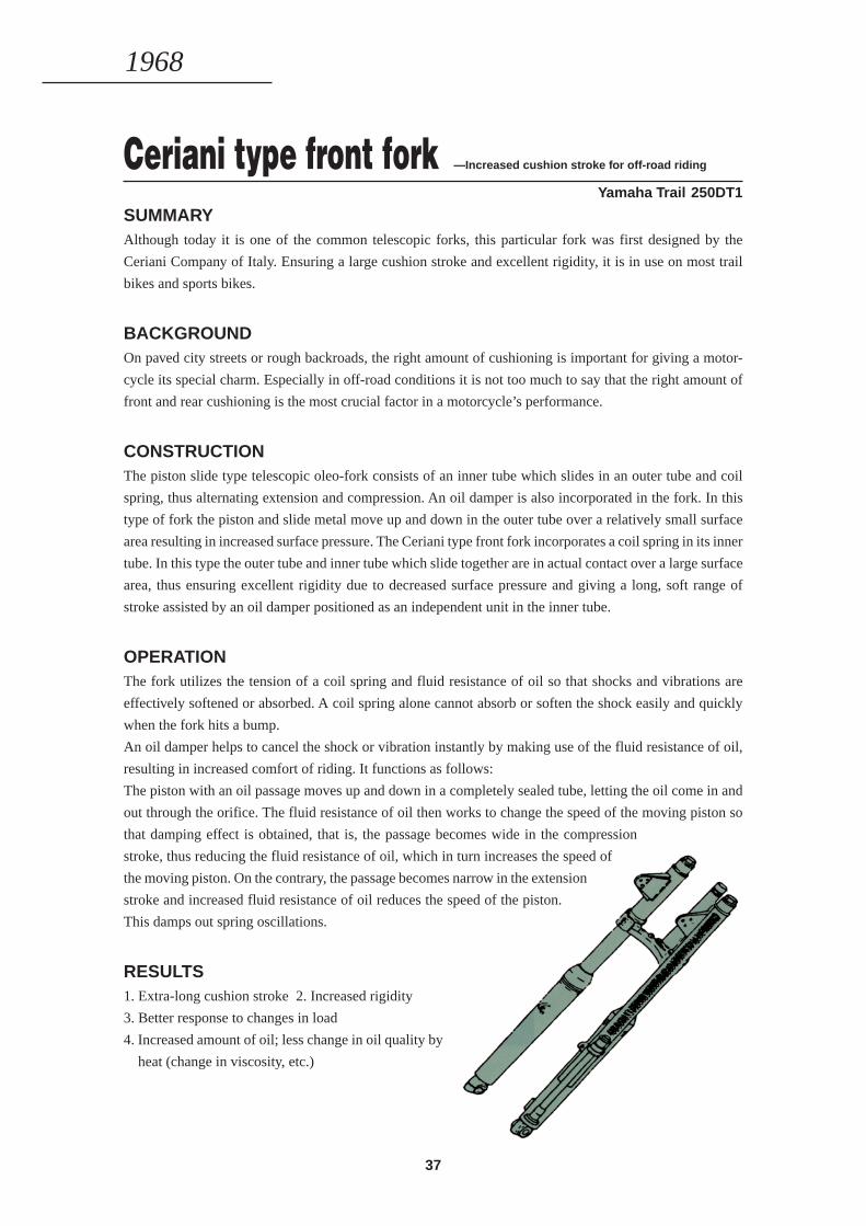
Ceriani type front fork —Increased cushion stroke for off-road riding
Yamaha Trail 250DT1
SUMMARYAlthough today it is one of the common telescopic forks, this particular fork was first designed by the
Ceriani Company of Italy. Ensuring a large cushion stroke and excellent rigidity, it is in use on most trail
bikes and sports bikes.
BACKGROUNDOn paved city streets or rough backroads, the right amount of cushioning is important for giving a motor-
cycle its special charm. Especially in off-road conditions it is not too much to say that the right amount of
front and rear cushioning is the most crucial factor in a motorcycle’s performance.
CONSTRUCTIONThe piston slide type telescopic oleo-fork consists of an inner tube which slides in an outer tube and coil
spring, thus alternating extension and compression. An oil damper is also incorporated in the fork. In this
type of fork the piston and slide metal move up and down in the outer tube over a relatively small surface
area resulting in increased surface pressure. The Ceriani type front fork incorporates a coil spring in its inner
tube. In this type the outer tube and inner tube which slide together are in actual contact over a large surface
area, thus ensuring excellent rigidity due to decreased surface pressure and giving a long, soft range of
stroke assisted by an oil damper positioned as an independent unit in the inner tube.
OPERATIONThe fork utilizes the tension of a coil spring and fluid resistance of oil so that shocks and vibrations are
effectively softened or absorbed. A coil spring alone cannot absorb or soften the shock easily and quickly
when the fork hits a bump.
An oil damper helps to cancel the shock or vibration instantly by making use of the fluid resistance of oil,
resulting in increased comfort of riding. It functions as follows:
The piston with an oil passage moves up and down in a completely sealed tube, letting the oil come in and
out through the orifice. The fluid resistance of oil then works to change the speed of the moving piston so
that damping effect is obtained, that is, the passage becomes wide in the compression
stroke, thus reducing the fluid resistance of oil, which in turn increases the speed of
the moving piston. On the contrary, the passage becomes narrow in the extension
stroke and increased fluid resistance of oil reduces the speed of the piston.
This damps out spring oscillations.
RESULTS1. Extra-long cushion stroke 2. Increased rigidity
3. Better response to changes in load
4. Increased amount of oil; less change in oil quality by
heat (change in viscosity, etc.)
1968
38
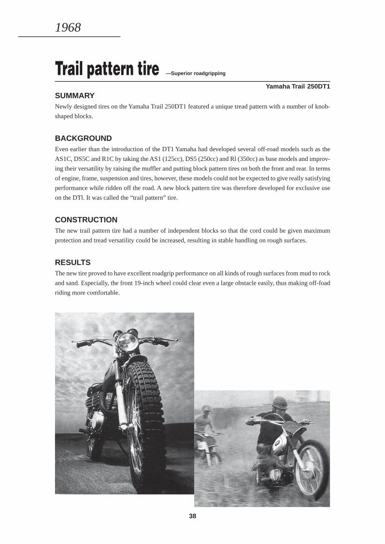
Trail pattern tire —Superior roadgripping
Yamaha Trail 250DT1
SUMMARYNewly designed tires on the Yamaha Trail 250DT1 featured a unique tread pattern with a number of knob-
shaped blocks.
BACKGROUNDEven earlier than the introduction of the DT1 Yamaha had developed several off-road models such as the
AS1C, DS5C and R1C by taking the AS1 (125cc), DS5 (250cc) and Rl (350cc) as base models and improv-
ing their versatility by raising the muffler and putting block pattern tires on both the front and rear. In terms
of engine, frame, suspension and tires, however, these models could not be expected to give really satisfying
performance while ridden off the road. A new block pattern tire was therefore developed for exclusive use
on the DTl. It was called the “trail pattern” tire.
CONSTRUCTIONThe new trail pattern tire had a number of independent blocks so that the cord could be given maximum
protection and tread versatility could be increased, resulting in stable handling on rough surfaces.
RESULTSThe new tire proved to have excellent roadgrip performance on all kinds of rough surfaces from mud to rock
and sand. Especially, the front 19-inch wheel could clear even a large obstacle easily, thus making off-foad
riding more comfortable.
1968
39
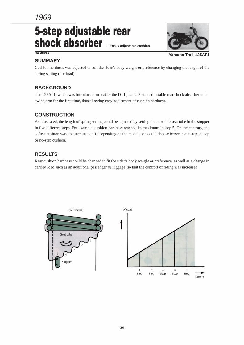
Yamaha Trail 125AT1
SUMMARYCushion hardness was adjusted to suit the rider’s body weight or preference by changing the length of the
spring setting (pre-load).
BACKGROUNDThe 125AT1, which was introduced soon after the DT1 , had a 5-step adjustable rear shock absorber on its
swing arm for the first time, thus allowing easy adjustment of cushion hardness.
CONSTRUCTIONAs illustrated, the length of spring setting could be adjusted by setting the movable seat tube in the stopper
in five different steps. For example, cushion hardness reached its maximum in step 5. On the contrary, the
softest cushion was obtained in step 1. Depending on the model, one could choose between a 5-step, 3-step
or no-step cushion.
RESULTSRear cushion hardness could be changed to fit the rider’s body weight or preference, as well as a change in
carried load such as an additional passenger or luggage, so that the comfort of riding was increased.
1969
5-step adjustable rearshock absorber —Easily adjustable cushion
hardness
Coil spring
Seat tube
Stopper
Weight
2Step
3Step
4Step
5Step
1Step
Stroke
1
2
5 43
40
Cover
Spring
Electromagnet
Adjust screw
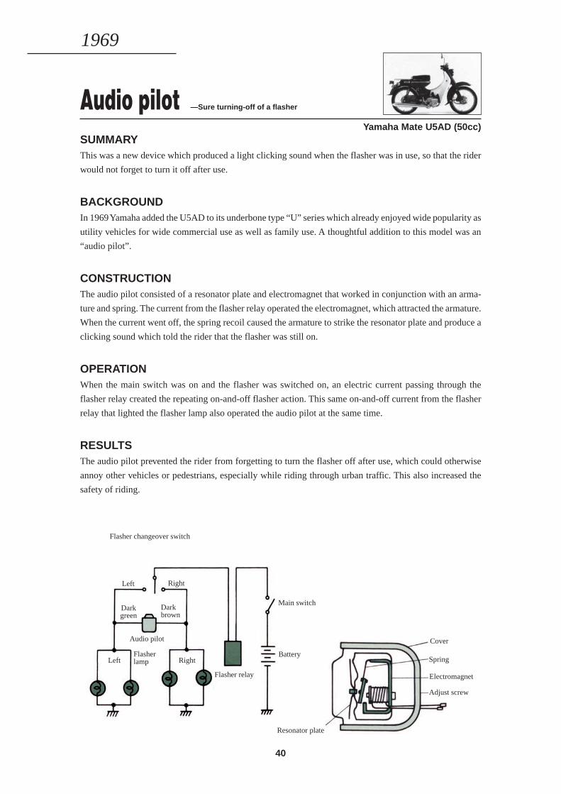
Audio pilot —Sure turning-off of a flasher
Yamaha Mate U5AD (50cc)SUMMARYThis was a new device which produced a light clicking sound when the flasher was in use, so that the rider
would not forget to turn it off after use.
BACKGROUNDIn 1969 Yamaha added the U5AD to its underbone type “U” series which already enjoyed wide popularity as
utility vehicles for wide commercial use as well as family use. A thoughtful addition to this model was an
“audio pilot”.
CONSTRUCTIONThe audio pilot consisted of a resonator plate and electromagnet that worked in conjunction with an arma-
ture and spring. The current from the flasher relay operated the electromagnet, which attracted the armature.
When the current went off, the spring recoil caused the armature to strike the resonator plate and produce a
clicking sound which told the rider that the flasher was still on.
OPERATIONWhen the main switch was on and the flasher was switched on, an electric current passing through the
flasher relay created the repeating on-and-off flasher action. This same on-and-off current from the flasher
relay that lighted the flasher lamp also operated the audio pilot at the same time.
RESULTSThe audio pilot prevented the rider from forgetting to turn the flasher off after use, which could otherwise
annoy other vehicles or pedestrians, especially while riding through urban traffic. This also increased the
safety of riding.
1969
Flasher changeover switch
Left Right
Darkgreen
Darkbrown
Audio pilot
LeftFlasherlamp Right
Main switch
Battery
Flasher relay
Resonator plate
41
1970—1974
BUILDING A QUALITY2 & 4-STROKE LINE-UP
42
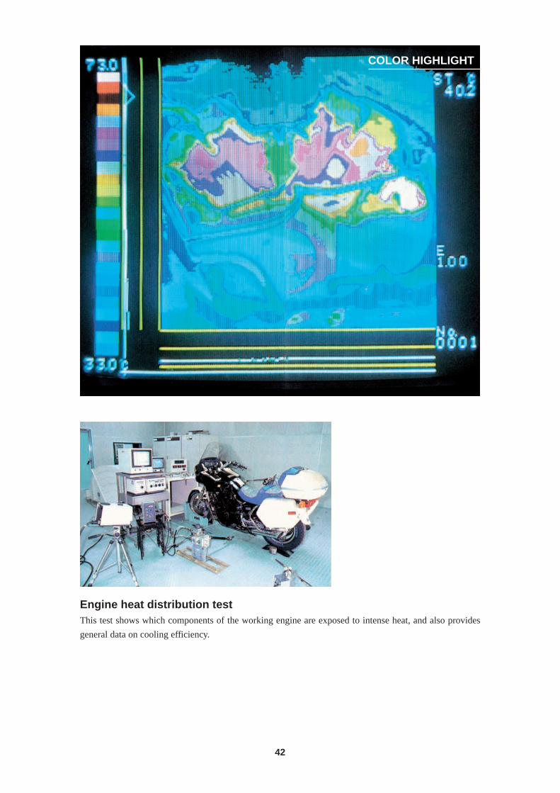
COLOR HIGHLIGHT
Engine heat distribution testThis test shows which components of the working engine are exposed to intense heat, and also provides
general data on cooling efficiency.
43
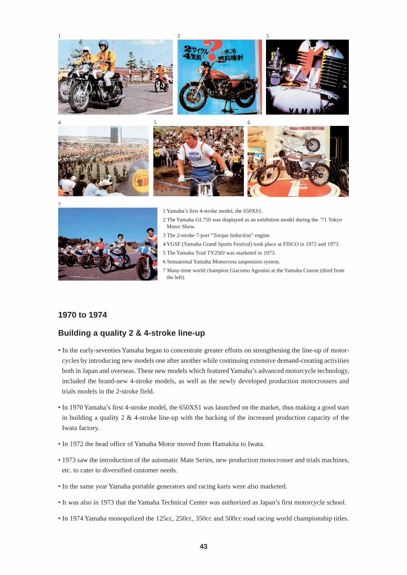
1 2 3
4 5 6
71 Yamaha’s first 4-stroke model, the 650XS1.
2 The Yamaha GL750 was displayed as an exhibition model during the ’71 TokyoMotor Show.
3 The 2-stroke 7-port “Torque Induction” engine.
4 YGSF (Yamaha Grand Sports Festival) took place at FISCO in 1972 and 1973.
5 The Yamaha Trial TY250J was marketed in 1973.
6 Sensational Yamaha Monocross suspension system.
7 Many-time world champion Giacomo Agostini at the Yamaha Course (third fromthe left).
1970 to 1974
Building a quality 2 & 4-stroke line-up
• In the early-seventies Yamaha began to concentrate greater efforts on strengthening the line-up of motor-
cycles by introducing new models one after another while continuing extensive demand-creating activities
both in Japan and overseas. These new models which featured Yamaha’s advanced motorcycle technology,
included the brand-new 4-stroke models, as well as the newly developed production motocrossers and
trials models in the 2-stroke field.
• In 1970 Yamaha’s first 4-stroke model, the 650XS1 was launched on the market, thus making a good start
in building a quality 2 & 4-stroke line-up with the backing of the increased production capacity of the
Iwata factory.
• In 1972 the head office of Yamaha Motor moved from Hamakita to Iwata.
• 1973 saw the introduction of the automatic Mate Series, new production motocrosser and trials machines,
etc. to cater to diversified customer needs.
• In the same year Yamaha portable generators and racing karts were also marketed.
• It was also in 1973 that the Yamaha Technical Center was authorized as Japan’s first motorcycle school.
• In 1974 Yamaha monopolized the 125cc, 250cc, 350cc and 500cc road racing world championship titles.
44
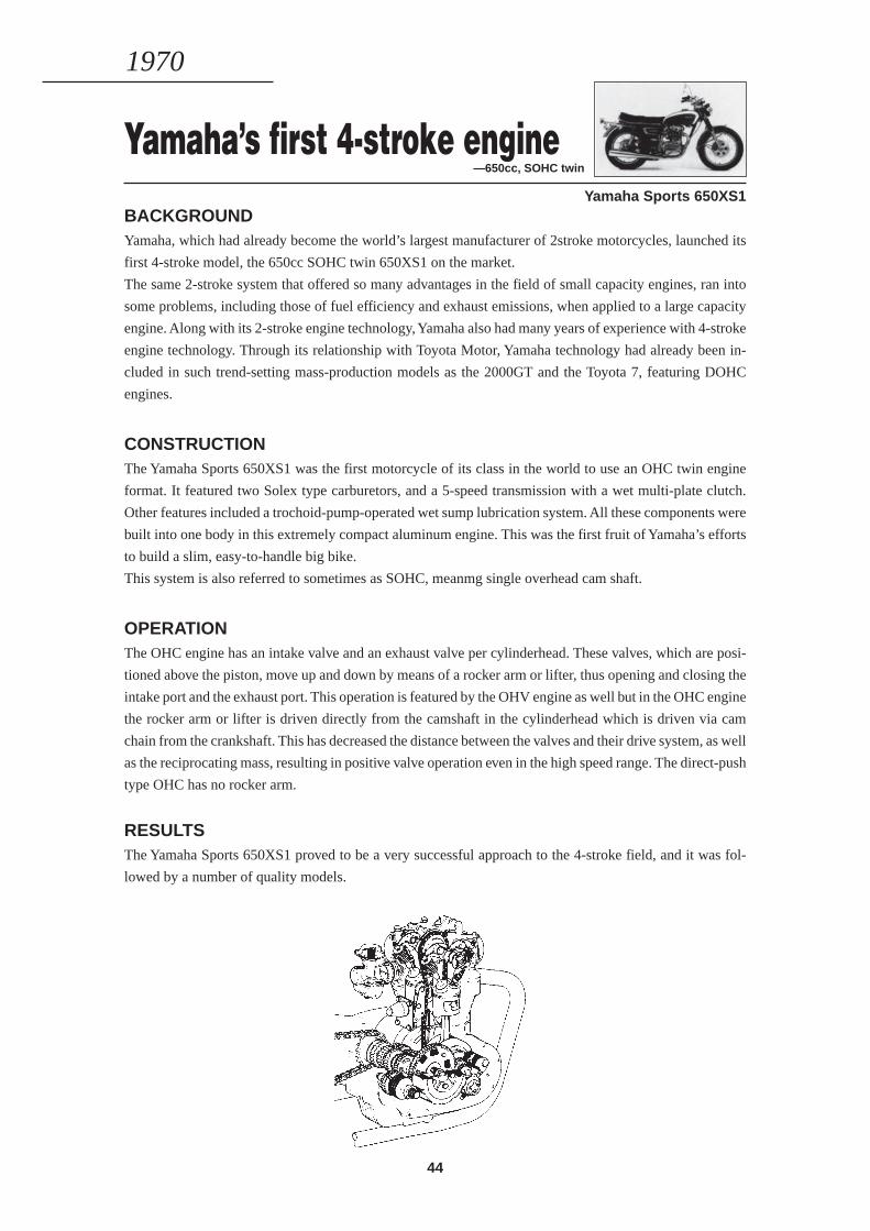
Yamaha’s first 4-stroke engine—650cc, SOHC twin
Yamaha Sports 650XS1BACKGROUNDYamaha, which had already become the world’s largest manufacturer of 2stroke motorcycles, launched its
first 4-stroke model, the 650cc SOHC twin 650XS1 on the market.
The same 2-stroke system that offered so many advantages in the field of small capacity engines, ran into
some problems, including those of fuel efficiency and exhaust emissions, when applied to a large capacity
engine. Along with its 2-stroke engine technology, Yamaha also had many years of experience with 4-stroke
engine technology. Through its relationship with Toyota Motor, Yamaha technology had already been in-
cluded in such trend-setting mass-production models as the 2000GT and the Toyota 7, featuring DOHC
engines.
CONSTRUCTIONThe Yamaha Sports 650XS1 was the first motorcycle of its class in the world to use an OHC twin engine
format. It featured two Solex type carburetors, and a 5-speed transmission with a wet multi-plate clutch.
Other features included a trochoid-pump-operated wet sump lubrication system. All these components were
built into one body in this extremely compact aluminum engine. This was the first fruit of Yamaha’s efforts
to build a slim, easy-to-handle big bike.
This system is also referred to sometimes as SOHC, meanmg single overhead cam shaft.
OPERATIONThe OHC engine has an intake valve and an exhaust valve per cylinderhead. These valves, which are posi-
tioned above the piston, move up and down by means of a rocker arm or lifter, thus opening and closing the
intake port and the exhaust port. This operation is featured by the OHV engine as well but in the OHC engine
the rocker arm or lifter is driven directly from the camshaft in the cylinderhead which is driven via cam
chain from the crankshaft. This has decreased the distance between the valves and their drive system, as well
as the reciprocating mass, resulting in positive valve operation even in the high speed range. The direct-push
type OHC has no rocker arm.
RESULTSThe Yamaha Sports 650XS1 proved to be a very successful approach to the 4-stroke field, and it was fol-
lowed by a number of quality models.
1970
45
Reed valve intake mechanism—Controlling the intake amount and timing
Yamaha Trail HT90SUMMARYThis was developed as a new kind of intake mechanism for the 2-stroke engine. In this mechanism the reed
valve opened and closed automatically with changes in pressure in the crankcase, so that the intake timing
and amount of air/fuel mixture was effectively controlled.
BACKGROUNDEffective intake control is a crucial factor in both the performance and fuel economy of the 2-stroke engine.
Following the introduction of the rotary valve intake mechanism, Yamaha developed this reed valve intake
mechanism.
CONSTRUCTIONThe reed valve intake mechanism is made of synthetic rubber over an aluminum frame which is shaped like
a harmonica with thin vibrator valves. This mechanism is incorporated in the intake manifold. The reed
valve opens and closes automatically with changes in pressure in the crankcase, and also intake inertia.
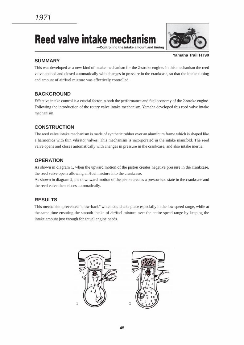
OPERATIONAs shown in diagram 1, when the upward motion of the piston creates negative pressure in the crankcase,
the reed valve opens allowing air/fuel mixture into the crankcase.
As shown in diagram 2, the downward motion of the piston creates a pressurized state in the crankcase and
the reed valve then closes automatically.
RESULTSThis mechanism prevented “blow-back” which could take place especially in the low speed range, while at
the same time ensuring the smooth intake of air/fuel mixture over the entire speed range by keeping the
intake amount just enough for actual engine needs.
1971
1 2
46
7-por t “Torque Induction”engine—Increased scavenging effect Yamaha Trail 175CT2
SUMMARYThis was developed as a new type of scavenging system for the 2-stroke engine. The system featured the
reed valve intake mechanism and the newly designed intake port with a cutaway on its upper part to provide
one more transfer passage . This cutaway passage which was added to a conventional 5-port scavenging
system (6 ports including the intake port) was called the “7th” port.
BACKGROUNDThe Yamaha Trail 175CT2 and the new DT250 and RT360 that were introduced soon after it, all used this
system so that the scavenging effect was increased, resulting in more power output.
CONSTRUCTIONThe scavenging function was performed by one intake port, one exhaust port, two main transfer ports, two
auxiliary transfer ports and the above “7th” port. During scavenging, when the intake port closed, fresh air/
fuel rnixture which had been compressed in the “7th” port, passed directly into the cylinder.
OPERATIONThe reed valve is a mechanism which closes when the downward motion of the piston creates a pressurized
state of air/fuel mixture in the crankcase, and opens when the upward motion of the piston produces nega-
tive pressure in the crankcase.
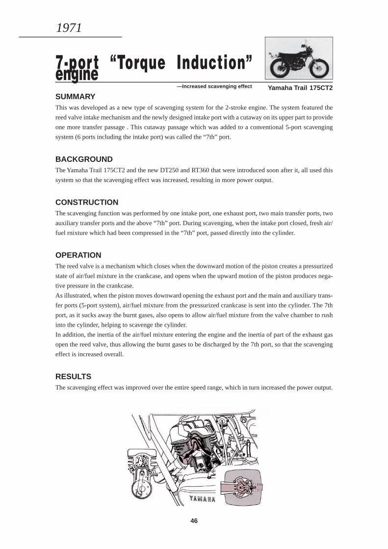
As illustrated, when the piston moves downward opening the exhaust port and the main and auxiliary trans-
fer ports (5-port system), air/fuel mixture from the pressurized crankcase is sent into the cylinder. The 7th
port, as it sucks away the burnt gases, also opens to allow air/fuel mixture from the valve chamber to rush
into the cylinder, helping to scavenge the cylinder.
In addition, the inertia of the air/fuel mixture entering the engine and the inertia of part of the exhaust gas
open the reed valve, thus allowing the burnt gases to be discharged by the 7th port, so that the scavenging
effect is increased overall.
RESULTSThe scavenging effect was improved over the entire speed range, which in turn increased the power output.
1971
47
Manual decompressor —Easier kick-starting
Yamaha Trail RT360SUMMARYThe decompressor is a device that decreases the compression pressure in the cylinder for easier kick-starting
of the engine.
BACKGROUNDThe Yamaha Trail RT360 was equipped with a Yamaha-original decompressor, dissimilar to a conventional
one, allowing the big single-cylinder engine to be started easily.
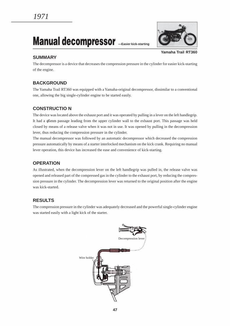
CONSTRUCTIO NThe device was located above the exhaust port and it was operated by pulling in a lever on the left handlegrip.
It had a φ5mm passage leading from the upper cylinder wall to the exhaust port. This passage was held
closed by means of a release valve when it was not in use. It was opened by pulling in the decompression
lever, thus reducing the compression pressure in the cylinder.
The manual decompressor was followed by an automatic decompressor which decreased the compression
pressure automatically by means of a starter interlocked mechanism on the kick crank. Requiring no manual
lever operation, this device has increased the ease and convenience of kick-starting.
OPERATIONAs illustrated, when the decompression lever on the left handlegrip was pulled in, the release valve was
opened and released part of the compressed gas in the cylinder to the exhaust port, by reducing the compres-
sion pressure in the cylinder. The decompression lever was returned to the original position after the engine
was kick-started.
RESULTSThe compression pressure in the cylinder was adequately decreased and the powerful single-cylinder engine
was started easily with a light kick of the starter.
1971
Decompression lever
Wire holder
48
Front disc brake —Hydraulic calipers
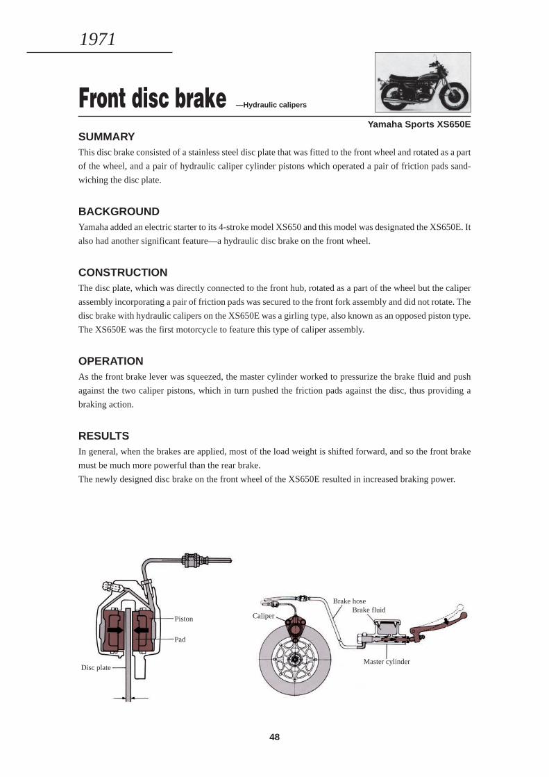
Yamaha Sports XS650ESUMMARYThis disc brake consisted of a stainless steel disc plate that was fitted to the front wheel and rotated as a part
of the wheel, and a pair of hydraulic caliper cylinder pistons which operated a pair of friction pads sand-
wiching the disc plate.
BACKGROUNDYamaha added an electric starter to its 4-stroke model XS650 and this model was designated the XS650E. It
also had another significant feature—a hydraulic disc brake on the front wheel.
CONSTRUCTIONThe disc plate, which was directly connected to the front hub, rotated as a part of the wheel but the caliper
assembly incorporating a pair of friction pads was secured to the front fork assembly and did not rotate. The
disc brake with hydraulic calipers on the XS650E was a girling type, also known as an opposed piston type.
The XS650E was the first motorcycle to feature this type of caliper assembly.
OPERATIONAs the front brake lever was squeezed, the master cylinder worked to pressurize the brake fluid and push
against the two caliper pistons, which in turn pushed the friction pads against the disc, thus providing a
braking action.
RESULTSIn general, when the brakes are applied, most of the load weight is shifted forward, and so the front brake
must be much more powerful than the rear brake.
The newly designed disc brake on the front wheel of the XS650E resulted in increased braking power.
1971
Brake hoseBrake fluid
Caliper
Master cylinder
Piston
Pad
Disc plate
49
Omni-phase balancer device—Reduced engine vibration
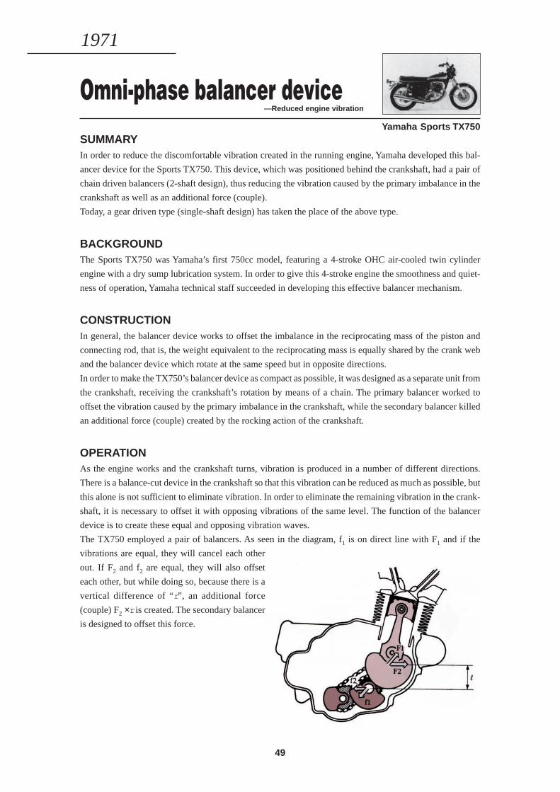
Yamaha Sports TX750SUMMARYIn order to reduce the discomfortable vibration created in the running engine, Yamaha developed this bal-
ancer device for the Sports TX750. This device, which was positioned behind the crankshaft, had a pair of
chain driven balancers (2-shaft design), thus reducing the vibration caused by the primary imbalance in the
crankshaft as well as an additional force (couple).
Today, a gear driven type (single-shaft design) has taken the place of the above type.
BACKGROUNDThe Sports TX750 was Yamaha’s first 750cc model, featuring a 4-stroke OHC air-cooled twin cylinder
engine with a dry sump lubrication system. In order to give this 4-stroke engine the smoothness and quiet-
ness of operation, Yamaha technical staff succeeded in developing this effective balancer mechanism.
CONSTRUCTIONIn general, the balancer device works to offset the imbalance in the reciprocating mass of the piston and
connecting rod, that is, the weight equivalent to the reciprocating mass is equally shared by the crank web
and the balancer device which rotate at the same speed but in opposite directions.
In order to make the TX750’s balancer device as compact as possible, it was designed as a separate unit from
the crankshaft, receiving the crankshaft’s rotation by means of a chain. The primary balancer worked to
offset the vibration caused by the primary imbalance in the crankshaft, while the secondary balancer killed
an additional force (couple) created by the rocking action of the crankshaft.
OPERATIONAs the engine works and the crankshaft turns, vibration is produced in a number of different directions.
There is a balance-cut device in the crankshaft so that this vibration can be reduced as much as possible, but
this alone is not sufficient to eliminate vibration. In order to eliminate the remaining vibration in the crank-
shaft, it is necessary to offset it with opposing vibrations of the same level. The function of the balancer
device is to create these equal and opposing vibration waves.
The TX750 employed a pair of balancers. As seen in the diagram, f1 is on direct line with F1 and if the
vibrations are equal, they will cancel each other
out. If F2 and f2 are equal, they will also offset
each other, but while doing so, because there is a
vertical difference of “r”, an additional force
(couple) F2 ×r is created. The secondary balancer
is designed to offset this force.
1971
50
Blow-by gas recirculating device—Effective recirculation of unburnt gas
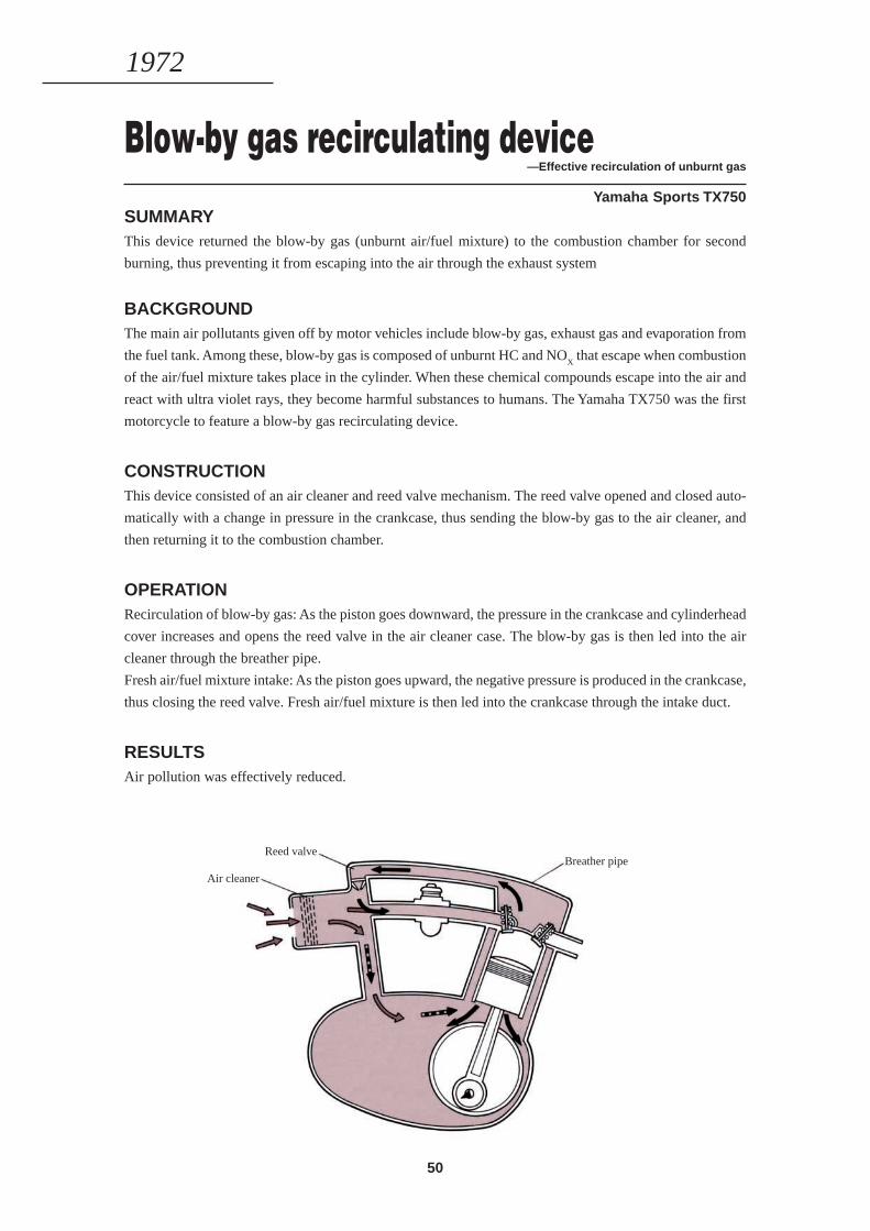
Yamaha Sports TX750SUMMARYThis device returned the blow-by gas (unburnt air/fuel mixture) to the combustion chamber for second
burning, thus preventing it from escaping into the air through the exhaust system
BACKGROUNDThe main air pollutants given off by motor vehicles include blow-by gas, exhaust gas and evaporation from
the fuel tank. Among these, blow-by gas is composed of unburnt HC and NOX that escape when combustion
of the air/fuel mixture takes place in the cylinder. When these chemical compounds escape into the air and
react with ultra violet rays, they become harmful substances to humans. The Yamaha TX750 was the first
motorcycle to feature a blow-by gas recirculating device.
CONSTRUCTIONThis device consisted of an air cleaner and reed valve mechanism. The reed valve opened and closed auto-
matically with a change in pressure in the crankcase, thus sending the blow-by gas to the air cleaner, and
then returning it to the combustion chamber.
OPERATIONRecirculation of blow-by gas: As the piston goes downward, the pressure in the crankcase and cylinderhead
cover increases and opens the reed valve in the air cleaner case. The blow-by gas is then led into the air
cleaner through the breather pipe.
Fresh air/fuel mixture intake: As the piston goes upward, the negative pressure is produced in the crankcase,
thus closing the reed valve. Fresh air/fuel mixture is then led into the crankcase through the intake duct.
RESULTSAir pollution was effectively reduced.
1972
Air cleaner
Reed valveBreather pipe
51
Aluminum rim —Decreased unsprung weight
Yamaha Sports TX750SUMMARYLightweight H-beam aluminum rims were used.
BACKGROUNDThe TX750 was the first street model to use H-beam aluminum rims on both the front and rear wheels.
RESULTSThese lightweight wheels became more responsive to varied road conditions due to decreased unsprung
weight, thus making the bike easier to handle.
1972
Reserve lighting switch —A device against lamp failure
Yamaha Sports TX750BACKGROUNDThis device was developed against the event of a headlamp or stoplamp becoming inoperative.
OPERATIONThe headlamp and the stop lamp were constructed so that if by some failure the lamp should go out, the
electrical current would automatically switch over to the other beam’s circuit as an emergency measure.
In case the tail lamp went out, the current switched over to a pilot lamp, thus turning it going on and off to
warn the rider that something was wrong with the lighting mechanism.
Connected righ & left exhaust pipes—Mutual exhaust interference for more power output
Yamaha Sports TX750SUMMARYThe right and left exhaust pipes were connected at a point close to the exhaust port, so that exhaust pulsa-
tions could affect each other for better engine performance.
RESULTSThis exhaust method resulted in a better silencing effect, as well as better engine performance for more
power output.
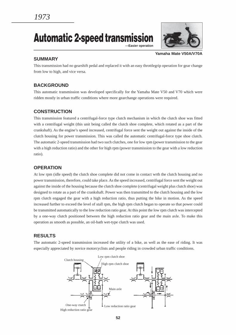
52
Automatic 2-speed transmission—Easier operation
Yamaha Mate V50A/V70ASUMMARYThis transmission had no gearshift pedal and replaced it with an easy throttlegrip operation for gear change
from low to high, and vice versa.
BACKGROUNDThis automatic transmission was developed specifically for the Yamaha Mate V50 and V70 which were
ridden mostly in urban traffic conditions where more gearchange operations were required.
CONSTRUCTIONThis transmission featured a centrifugal-force type clutch mechanism in which the clutch shoe was fitted
with a centrifugal weight (this unit being called the clutch shoe complete, which rotated as a part of the
crankshaft). As the engine’s speed increased, centrifugal force sent the weight out against the inside of the
clutch housing for power transmission. This was called the automatic centrifugal-force type shoe clutch.
The automatic 2-speed transmission had two such clutches, one for low rpm (power transmission to the gear
with a high reduction ratio) and the other for high rpm (power transmission to the gear with a low reduction
ratio).
OPERATIONAt low rpm (idle speed) the clutch shoe complete did not come in contact wrth the clutch housing and no
power transmission, therefore, could take place. As the speed increased, centrifugal force sent the weight out
against the inside of the housing because the clutch shoe complete (centrifugal weight plus clutch shoe) was
designed to rotate as a part of the crankshaft. Power was then transmitted to the clutch housing and the low
rpm clutch engaged the gear with a high reduction ratio, thus putting the bike in motion. As the speed
increased further to exceed the level of stall rpm, the high rpm clutch began to operate so that power could
be transmitted automatically to the low reduction ratio gear. At this point the low rpm clutch was intercepted
by a one-way clutch positioned between the high reduction ratio gear and the main axle. To make this
operation as smooth as possible, an oil-bath wet-type clutch was used.
RESULTSThe automatic 2-speed transmission increased the utility of a bike, as well as the ease of riding. It was
especially appreciated by novice motorcyclists and people riding in crowded urban traffic conditions.
1973
Clutch housingLow rpm clutch shoe
High rpm clutch shoe
Main axle
One-way ctutch Low reduction ratio gearHigh reduction ratio gear
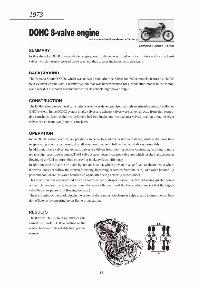
53
DOHC 8-valve engine—Increased intake/exhaust efficiency
Yamaha Sports TX500SUMMARYIn this 4-stroke DOHC twin-cylinder engine, each cylinder was fitted with two intake and two exhaust
valves, which meant increased valve area and thus greater intake/exhaust efficiency.
BACKGROUNDThe Yamaha Sports TX500, which was released soon after the 650cc and 750cc models, featured a DOHC
twin-cylinder engine with a 8-valve system that was unprecedented for a production model in the motor-
cycle world. This model became known for its reliable high power output.
CONSTRUCTIONThe DOHC (double overhead camshafts) system was developed from a single overhead camshaft (SOHC or
OHC) system. In the DOHC system intake valves and exhaust valves were driven directly from their respec-
tive camshafts. Each of the two cylinders had two intake and two exhaust valves, making a total of eight
valves driven from two (double) camshafts.
OPERATIONIn the DOHC system each valve operation can be performed over a shorter distance, while at the same time
reciprocating mass is decreased, thus allowing each valve to follow the camshaft very smoothly.
In addition, intake valves and exhaust valves are driven from their respective camshafts, resulting in more
reliable high-speed power output. The 8-valve system means increased valve area which results in the smoother
flowing of air/fuel mixture, thus improving intake/exhaust efficiency.
In addition, each valve can be made lighter and smaller, which prevents “valve float” (a phenomenon where
the valve does not follow the camshaft exactly, becoming separated from the cam), or “valve bounce” (a
phenomenon where the valve bounces up again after being correctly seated once),
This means that the engine could function over a wider high speed range, thereby delivering greater power
output. (In general, the greater the mass, the greater the inertia of the body, which means that the bigger
valve becomes poorer in following the cam.)
The positioning of the spark plug in the center of the combustion chamber helps greatly to improve combus-
tion efficiency by ensuring better flame propagation.
RESULTSThe 8-valve DOHC twin-cylinder engine
earned the Sports TX500 a position on the
market because of its reliable high perfor-
mance.
1973
EX
IN
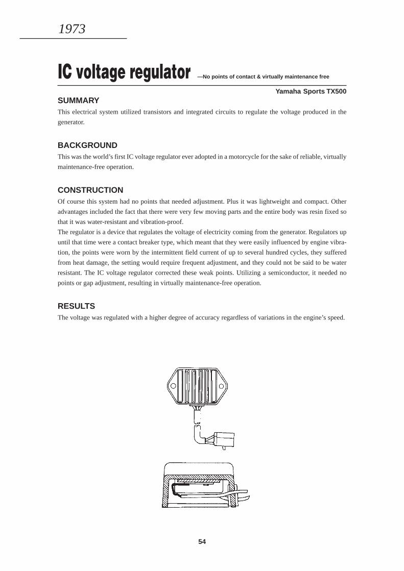
54
IC voltage regulator —No points of contact & virtually maintenance free
Yamaha Sports TX500SUMMARYThis electrical system utilized transistors and integrated circuits to regulate the voltage produced in the
generator.
BACKGROUNDThis was the world’s first IC voltage regulator ever adopted in a motorcycle for the sake of reliable, virtually
maintenance-free operation.
CONSTRUCTIONOf course this system had no points that needed adjustment. Plus it was lightweight and compact. Other
advantages included the fact that there were very few moving parts and the entire body was resin fixed so
that it was water-resistant and vibration-proof.
The regulator is a device that regulates the voltage of electricity coming from the generator. Regulators up
until that time were a contact breaker type, which meant that they were easily influenced by engine vibra-
tion, the points were worn by the intermittent field current of up to several hundred cycles, they suffered
from heat damage, the setting would require frequent adjustment, and they could not be said to be water
resistant. The IC voltage regulator corrected these weak points. Utilizing a semiconductor, it needed no
points or gap adjustment, resulting in virtually maintenance-free operation.
RESULTSThe voltage was regulated with a higher degree of accuracy regardless of variations in the engine’s speed.
1973
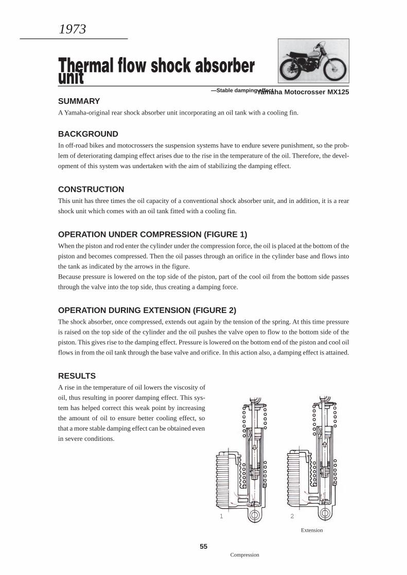
55
1 2
Compression
Extension
Thermal flow shock absorberunit—Stable damping effectYamaha Motocrosser MX125
SUMMARYA Yamaha-original rear shock absorber unit incorporating an oil tank with a cooling fin.
BACKGROUNDIn off-road bikes and motocrossers the suspension systems have to endure severe punishment, so the prob-
lem of deteriorating damping effect arises due to the rise in the temperature of the oil. Therefore, the devel-
opment of this system was undertaken with the aim of stabilizing the damping effect.
CONSTRUCTIONThis unit has three times the oil capacity of a conventional shock absorber unit, and in addition, it is a rear
shock unit which comes with an oil tank fitted with a cooling fin.
OPERATION UNDER COMPRESSION (FIGURE 1)When the piston and rod enter the cylinder under the compression force, the oil is placed at the bottom of the
piston and becomes compressed. Then the oil passes through an orifice in the cylinder base and flows into
the tank as indicated by the arrows in the figure.
Because pressure is lowered on the top side of the piston, part of the cool oil from the bottom side passes
through the valve into the top side, thus creating a damping force.
OPERATION DURING EXTENSION (FIGURE 2)The shock absorber, once compressed, extends out again by the tension of the spring. At this time pressure
is raised on the top side of the cylinder and the oil pushes the valve open to flow to the bottom side of the
piston. This gives rise to the damping effect. Pressure is lowered on the bottom end of the piston and cool oil
flows in from the oil tank through the base valve and orifice. In this action also, a damping effect is attained.
RESULTSA rise in the temperature of oil lowers the viscosity of
oil, thus resulting in poorer damping effect. This sys-
tem has helped correct this weak point by increasing
the amount of oil to ensure better cooling effect, so
that a more stable damping effect can be obtained even
in severe conditions.
1973
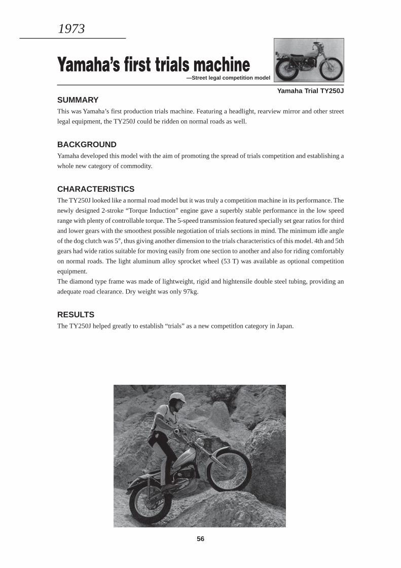
56
Yamaha’s first trials machine—Street legal competition model
Yamaha Trial TY250JSUMMARYThis was Yamaha’s first production trials machine. Featuring a headlight, rearview mirror and other street
legal equipment, the TY250J could be ridden on normal roads as well.
BACKGROUNDYamaha developed this model with the aim of promoting the spread of trials competition and establishing a
whole new category of commodity.
CHARACTERISTICSThe TY250J looked like a normal road model but it was truly a competition machine in its performance. The
newly designed 2-stroke “Torque Induction” engine gave a superbly stable performance in the low speed
range with plenty of controllable torque. The 5-speed transmission featured specially set gear ratios for third
and lower gears with the smoothest possible negotiation of trials sections in mind. The minimum idle angle
of the dog clutch was 5°, thus giving another dimension to the trials characteristics of this model. 4th and 5th
gears had wide ratios suitable for moving easily from one section to another and also for riding comfortably
on normal roads. The light aluminum alloy sprocket wheel (53 T) was available as optional competition
equipment.
The diamond type frame was made of lightweight, rigid and hightensile double steel tubing, providing an
adequate road clearance. Dry weight was only 97kg.
RESULTSThe TY250J helped greatly to establish “trials” as a new competitlon category in Japan.
1973
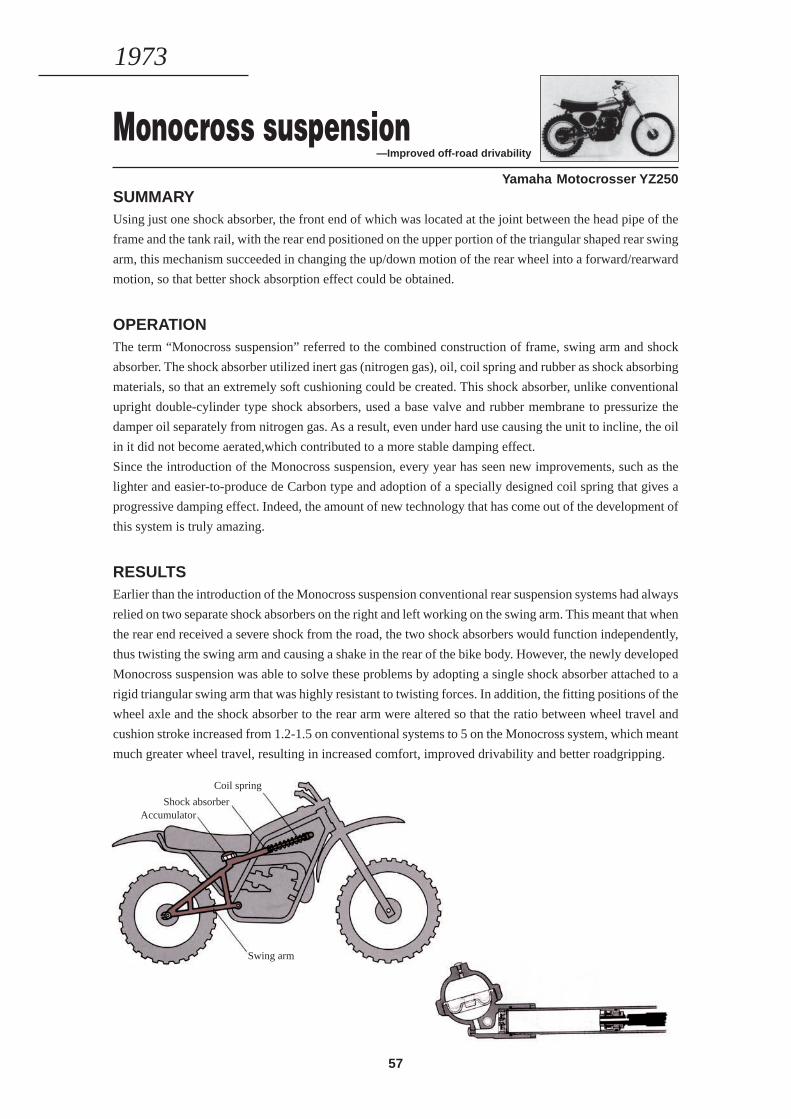
57
Monocross suspension—Improved off-road drivability
Yamaha Motocrosser YZ250SUMMARYUsing just one shock absorber, the front end of which was located at the joint between the head pipe of the
frame and the tank rail, with the rear end positioned on the upper portion of the triangular shaped rear swing
arm, this mechanism succeeded in changing the up/down motion of the rear wheel into a forward/rearward
motion, so that better shock absorption effect could be obtained.
OPERATIONThe term “Monocross suspension” referred to the combined construction of frame, swing arm and shock
absorber. The shock absorber utilized inert gas (nitrogen gas), oil, coil spring and rubber as shock absorbing
materials, so that an extremely soft cushioning could be created. This shock absorber, unlike conventional
upright double-cylinder type shock absorbers, used a base valve and rubber membrane to pressurize the
damper oil separately from nitrogen gas. As a result, even under hard use causing the unit to incline, the oil
in it did not become aerated,which contributed to a more stable damping effect.
Since the introduction of the Monocross suspension, every year has seen new improvements, such as the
lighter and easier-to-produce de Carbon type and adoption of a specially designed coil spring that gives a
progressive damping effect. Indeed, the amount of new technology that has come out of the development of
this system is truly amazing.
RESULTSEarlier than the introduction of the Monocross suspension conventional rear suspension systems had always
relied on two separate shock absorbers on the right and left working on the swing arm. This meant that when
the rear end received a severe shock from the road, the two shock absorbers would function independently,
thus twisting the swing arm and causing a shake in the rear of the bike body. However, the newly developed
Monocross suspension was able to solve these problems by adopting a single shock absorber attached to a
rigid triangular swing arm that was highly resistant to twisting forces. In addition, the fitting positions of the
wheel axle and the shock absorber to the rear arm were altered so that the ratio between wheel travel and
cushion stroke increased from 1.2-1.5 on conventional systems to 5 on the Monocross system, which meant
much greater wheel travel, resulting in increased comfort, improved drivability and better roadgripping.
1973
Coil spring
Shock absorberAccumulator
Swing arm
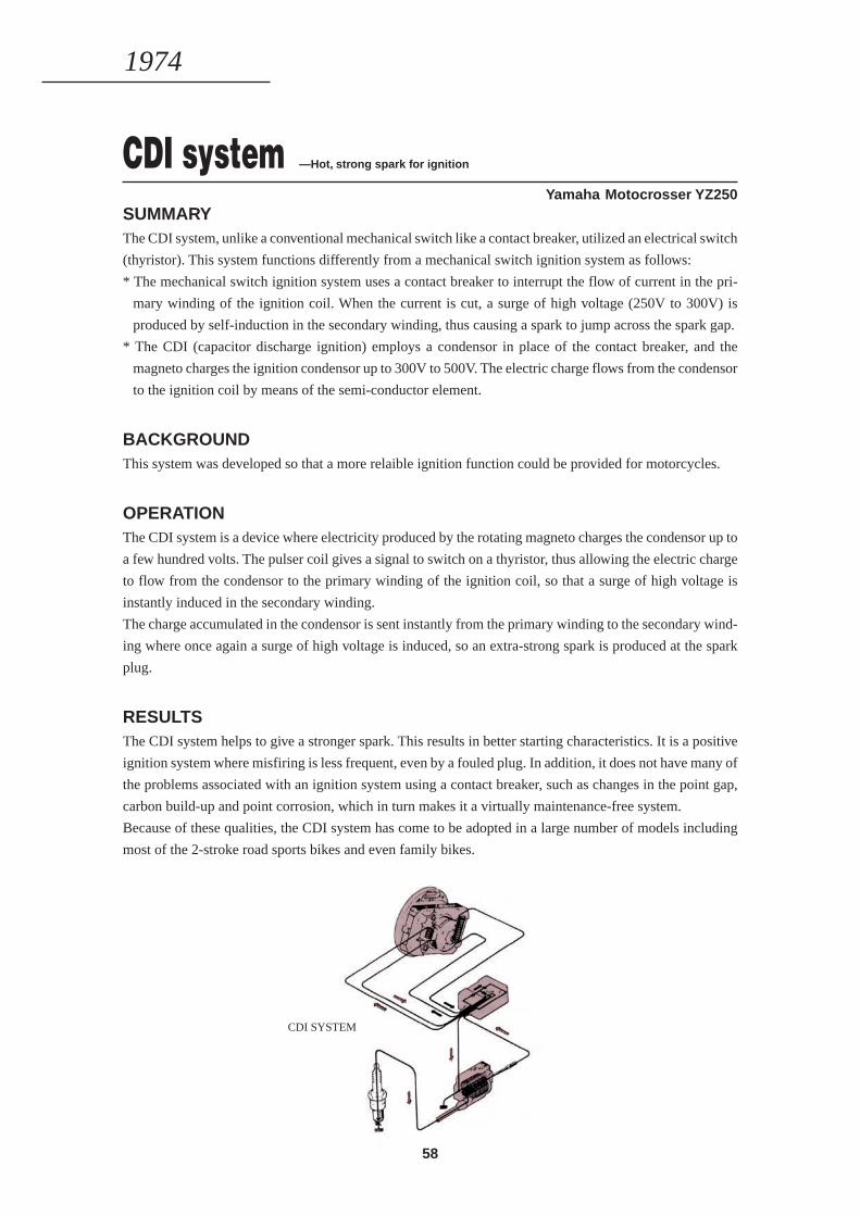
58
CDI system —Hot, strong spark for ignition
Yamaha Motocrosser YZ250SUMMARYThe CDI system, unlike a conventional mechanical switch like a contact breaker, utilized an electrical switch
(thyristor). This system functions differently from a mechanical switch ignition system as follows:
* The mechanical switch ignition system uses a contact breaker to interrupt the flow of current in the pri-
mary winding of the ignition coil. When the current is cut, a surge of high voltage (250V to 300V) is
produced by self-induction in the secondary winding, thus causing a spark to jump across the spark gap.
* The CDI (capacitor discharge ignition) employs a condensor in place of the contact breaker, and the
magneto charges the ignition condensor up to 300V to 500V. The electric charge flows from the condensor
to the ignition coil by means of the semi-conductor element.
BACKGROUNDThis system was developed so that a more relaible ignition function could be provided for motorcycles.
OPERATIONThe CDI system is a device where electricity produced by the rotating magneto charges the condensor up to
a few hundred volts. The pulser coil gives a signal to switch on a thyristor, thus allowing the electric charge
to flow from the condensor to the primary winding of the ignition coil, so that a surge of high voltage is
instantly induced in the secondary winding.
The charge accumulated in the condensor is sent instantly from the primary winding to the secondary wind-
ing where once again a surge of high voltage is induced, so an extra-strong spark is produced at the spark
plug.
RESULTSThe CDI system helps to give a stronger spark. This results in better starting characteristics. It is a positive
ignition system where misfiring is less frequent, even by a fouled plug. In addition, it does not have many of
the problems associated with an ignition system using a contact breaker, such as changes in the point gap,
carbon build-up and point corrosion, which in turn makes it a virtually maintenance-free system.
Because of these qualities, the CDI system has come to be adopted in a large number of models including
most of the 2-stroke road sports bikes and even family bikes.
1974
CDI SYSTEM

59
1975—1979
CONTINUED EFFORTSTO MEET DIVERSIFIED
CUSTOMER NEEDS
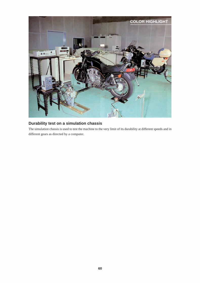
60
COLOR HIGHLIGHT
Durability test on a simulation chassisThe simulation chassis is used to test the machine to the very limit of its durability at different speeds and in
different gears as directed by a computer.
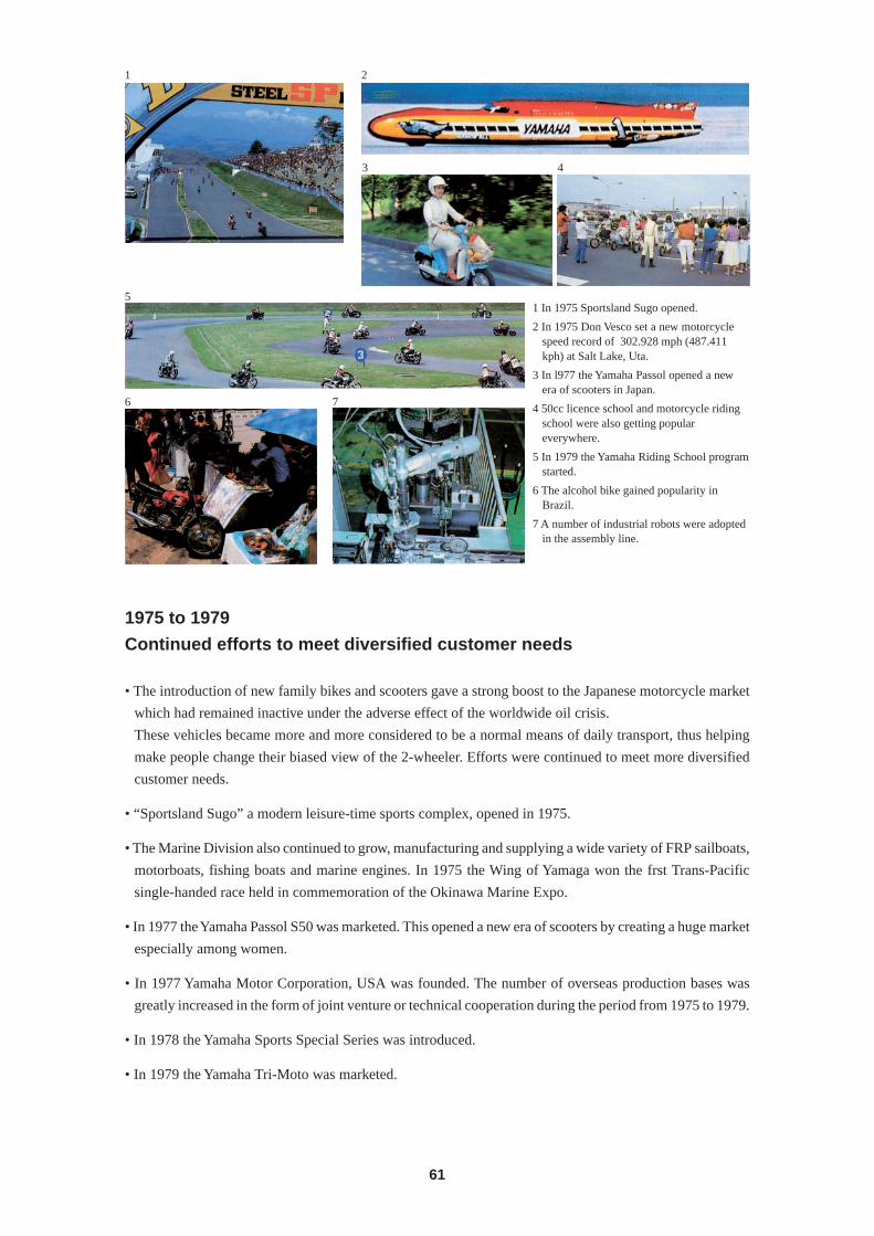
61
1 2
3 4
5
6 7
1 In 1975 Sportsland Sugo opened.
2 In 1975 Don Vesco set a new motorcyclespeed record of 302.928 mph (487.411kph) at Salt Lake, Uta.
3 In l977 the Yamaha Passol opened a newera of scooters in Japan.
4 50cc licence school and motorcycle ridingschool were also getting populareverywhere.
5 In 1979 the Yamaha Riding School programstarted.
6 The alcohol bike gained popularity inBrazil.
7 A number of industrial robots were adoptedin the assembly line.
1975 to 1979
Continued efforts to meet diversified customer needs
• The introduction of new family bikes and scooters gave a strong boost to the Japanese motorcycle market
which had remained inactive under the adverse effect of the worldwide oil crisis.
These vehicles became more and more considered to be a normal means of daily transport, thus helping
make people change their biased view of the 2-wheeler. Efforts were continued to meet more diversified
customer needs.
• “Sportsland Sugo” a modern leisure-time sports complex, opened in 1975.
• The Marine Division also continued to grow, manufacturing and supplying a wide variety of FRP sailboats,
motorboats, fishing boats and marine engines. In 1975 the Wing of Yamaga won the frst Trans-Pacific
single-handed race held in commemoration of the Okinawa Marine Expo.
• In 1977 the Yamaha Passol S50 was marketed. This opened a new era of scooters by creating a huge market
especially among women.
• In 1977 Yamaha Motor Corporation, USA was founded. The number of overseas production bases was
greatly increased in the form of joint venture or technical cooperation during the period from 1975 to 1979.
• In 1978 the Yamaha Sports Special Series was introduced.
• In 1979 the Yamaha Tri-Moto was marketed.
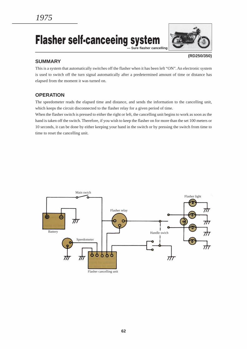
62
Flasher self-canceeing system— Sure flasher cancelling
(RD250/350)SUMMARYThis is a system that automatically switches off the flasher when it has been left “ON”. An electronic system
is used to switch off the turn signal automatically after a predetermined amount of time or distance has
elapsed from the moment it was turned on.
OPERATIONThe speedometer reads the elapsed time and distance, and sends the information to the cancelling unit,
which keeps the circuit disconnected to the flasher relay for a given period of time.
When the flasher switch is pressed to either the right or left, the cancelling unit begins to work as soon as the
hand is taken off the switch. Therefore, if you wish to keep the flasher on for more than the set 100 meters or
10 seconds, it can be done by either keeping your hand in the switch or by pressing the switch from time to
time to reset the cancelling unit.
1975
Main swich
Battery
Speedometer
Flasher relay
Flasher cancelling unit
Flasher light
Handle swich
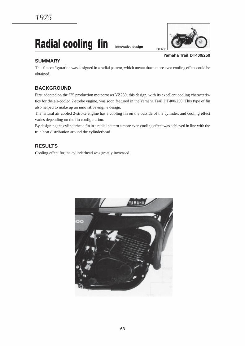
63
Radial cooling fin —Innovative design
Yamaha Trail DT400/250SUMMARYThis fin configuration was designed in a radial pattern, which meant that a more even cooling effect could be
obtained.
BACKGROUNDFirst adopted on the ’75 production motocrosser YZ250, this design, with its excellent cooling characteris-
tics for the air-cooled 2-stroke engine, was soon featured in the Yamaha Trail DT400/250. This type of fin
also helped to make up an innovative engine design.
The natural air cooled 2-stroke engine has a cooling fin on the outside of the cylinder, and cooling effect
varies depending on the fin configuration.
By designing the cylinderhead fin in a radial pattern a more even cooling effect was achieved in line with the
true heat distribution around the cylinderhead.
RESULTSCooling effect for the cylinderhead was greatly increased.
1975
DT400
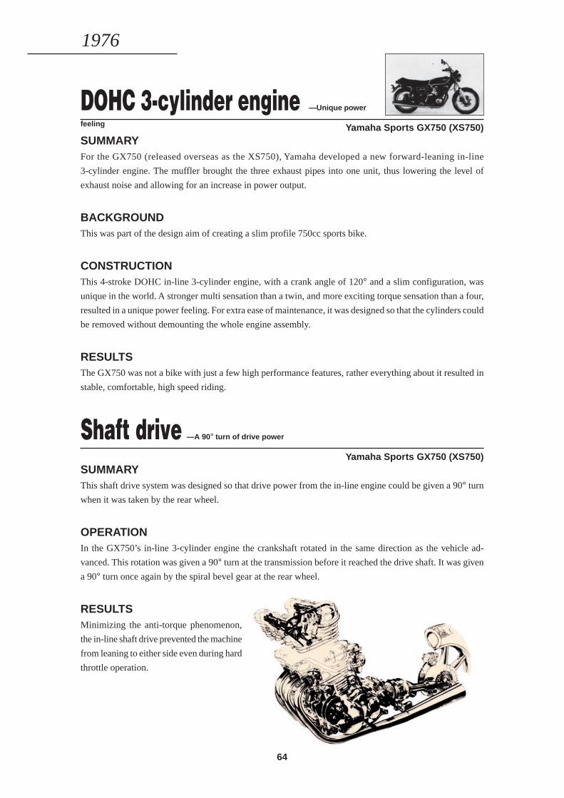
64
DOHC 3-cylinder engine —Unique power
feeling Yamaha Sports GX750 (XS750)SUMMARYFor the GX750 (released overseas as the XS750), Yamaha developed a new forward-leaning in-line
3-cylinder engine. The muffler brought the three exhaust pipes into one unit, thus lowering the level of
exhaust noise and allowing for an increase in power output.
BACKGROUNDThis was part of the design aim of creating a slim profile 750cc sports bike.
CONSTRUCTIONThis 4-stroke DOHC in-line 3-cylinder engine, with a crank angle of 120° and a slim configuration, was
unique in the world. A stronger multi sensation than a twin, and more exciting torque sensation than a four,
resulted in a unique power feeling. For extra ease of maintenance, it was designed so that the cylinders could
be removed without demounting the whole engine assembly.
RESULTSThe GX750 was not a bike with just a few high performance features, rather everything about it resulted in
stable, comfortable, high speed riding.
1976
Shaft drive —A 90° turn of drive power
Yamaha Sports GX750 (XS750)SUMMARYThis shaft drive system was designed so that drive power from the in-line engine could be given a 90° turn
when it was taken by the rear wheel.
OPERATIONIn the GX750’s in-line 3-cylinder engine the crankshaft rotated in the same direction as the vehicle ad-
vanced. This rotation was given a 90° turn at the transmission before it reached the drive shaft. It was given
a 90° turn once again by the spiral bevel gear at the rear wheel.
RESULTSMinimizing the anti-torque phenomenon,
the in-line shaft drive prevented the machine
from leaning to either side even during hard
throttle operation.
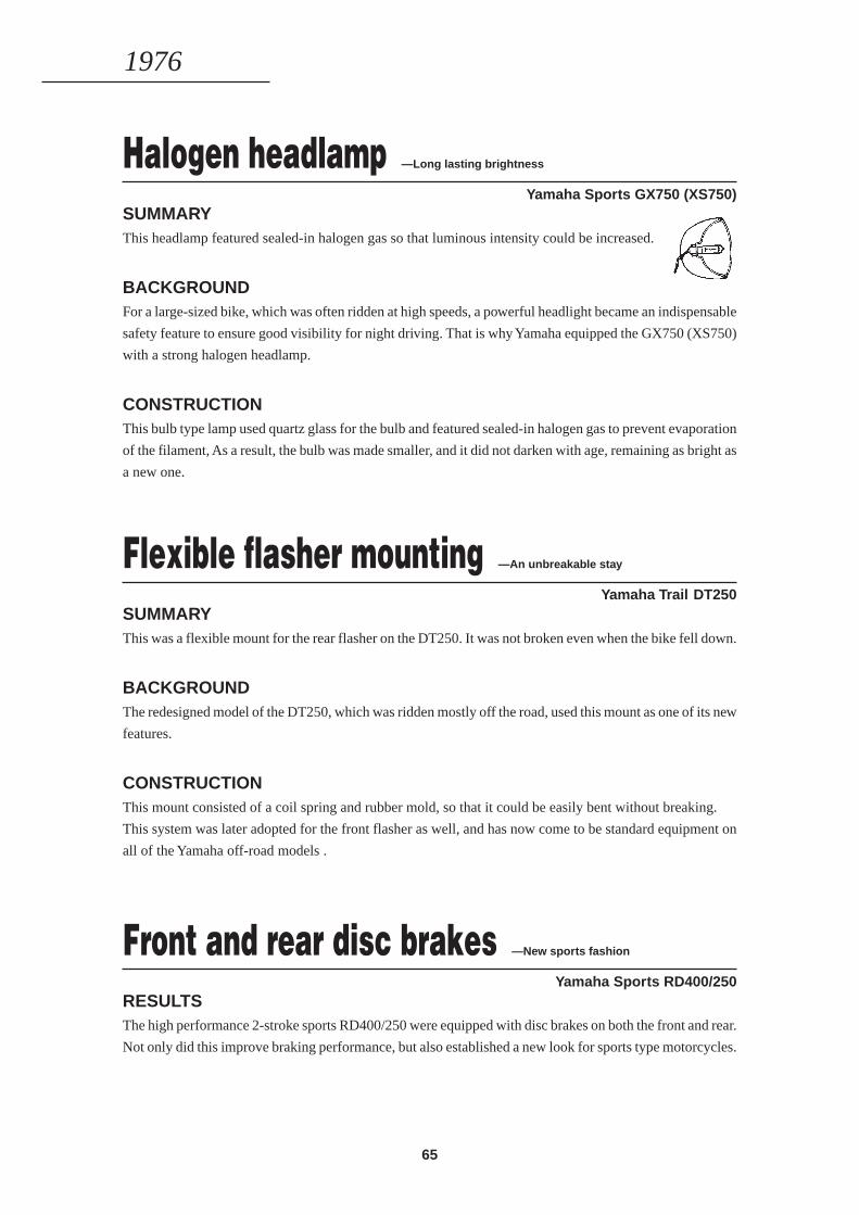
65
Halogen headlamp —Long lasting brightness
Yamaha Sports GX750 (XS750)SUMMARYThis headlamp featured sealed-in halogen gas so that luminous intensity could be increased.
BACKGROUNDFor a large-sized bike, which was often ridden at high speeds, a powerful headlight became an indispensable
safety feature to ensure good visibility for night driving. That is why Yamaha equipped the GX750 (XS750)
with a strong halogen headlamp.
CONSTRUCTIONThis bulb type lamp used quartz glass for the bulb and featured sealed-in halogen gas to prevent evaporation
of the filament, As a result, the bulb was made smaller, and it did not darken with age, remaining as bright as
a new one.
1976
Flexible flasher mounting —An unbreakable stay
Yamaha Trail DT250SUMMARYThis was a flexible mount for the rear flasher on the DT250. It was not broken even when the bike fell down.
BACKGROUNDThe redesigned model of the DT250, which was ridden mostly off the road, used this mount as one of its new
features.
CONSTRUCTIONThis mount consisted of a coil spring and rubber mold, so that it could be easily bent without breaking.
This system was later adopted for the front flasher as well, and has now come to be standard equipment on
all of the Yamaha off-road models .
Front and rear disc brakes —New sports fashion
Yamaha Sports RD400/250RESULTSThe high performance 2-stroke sports RD400/250 were equipped with disc brakes on both the front and rear.
Not only did this improve braking performance, but also established a new look for sports type motorcycles.
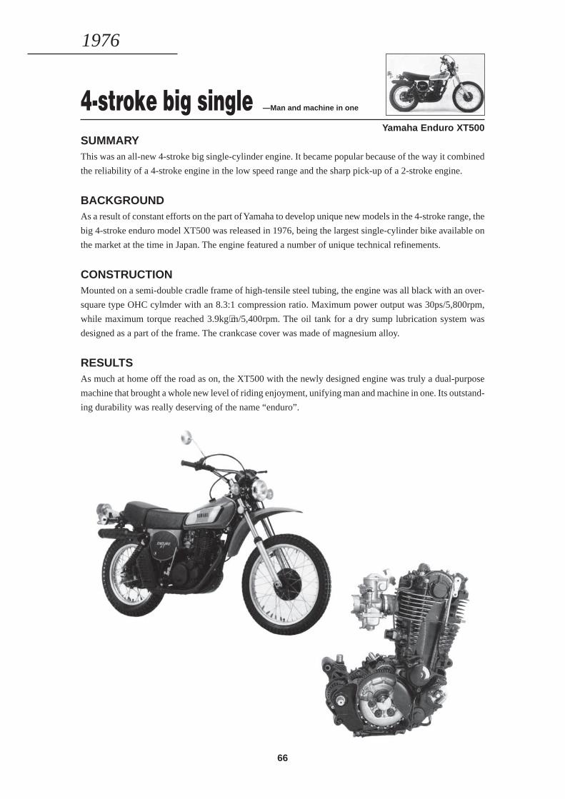
66
4-stroke big single —Man and machine in one
Yamaha Enduro XT500SUMMARYThis was an all-new 4-stroke big single-cylinder engine. It became popular because of the way it combined
the reliability of a 4-stroke engine in the low speed range and the sharp pick-up of a 2-stroke engine.
BACKGROUNDAs a result of constant efforts on the part of Yamaha to develop unique new models in the 4-stroke range, the
big 4-stroke enduro model XT500 was released in 1976, being the largest single-cylinder bike available on
the market at the time in Japan. The engine featured a number of unique technical refinements.
CONSTRUCTIONMounted on a semi-double cradle frame of high-tensile steel tubing, the engine was all black with an over-
square type OHC cylmder with an 8.3:1 compression ratio. Maximum power output was 30ps/5,800rpm,
while maximum torque reached 3.9kg⋅m/5,400rpm. The oil tank for a dry sump lubrication system was
designed as a part of the frame. The crankcase cover was made of magnesium alloy.
RESULTSAs much at home off the road as on, the XT500 with the newly designed engine was truly a dual-purpose
machine that brought a whole new level of riding enjoyment, unifying man and machine in one. Its outstand-
ing durability was really deserving of the name “enduro”.
1976

67
In-frame oil tank design —Slim chassis design
Yamaha Enduro XT500SUMMARYThe oil tank on the XT500 was designed as a part of the frame, thus resulting in very effective dry sump
lubrication.
BACKGROUNDThe in-frame oil tank design allowed the engine to be positioned higher in the frame for greater ground
clearance which was a must for off-road riding, while chassis construction was made slim and compact.
CONSTRUCTIONIn this unique in-frame oil tank design, the upper cross member joining the steering head held the oil, which
passed through the forward down tube to the engine and then was sent back to the upper cross member. This
was called a forced-pressure dry sump lubrication system, thus eliminating the need for a separate oil reser-
voir that was indispensable to the wet sump lubrication system on most 4-stroke engines. This also helped to
reduce the overall height of the engine, resulting in greater ground clearance for smoother off-road riding. In
addition, a dry sump lubrication model, as is also seen on a number of 2-stroke models, must usually have an
oil tank fitted to the side cover, but on the XT500 this need was eliminated. This allowed for a slimmer body
at the riding position, which meant that the rider could take a freer, more natural position for off-road riding.
RESULTSThis lightweight, compact chassis design enabled the rider to take a better riding position, while at the same
time allowing the adoption of a large-capacity air cleaner.
1976
’82 XT500
’76 XT500
Top cross member
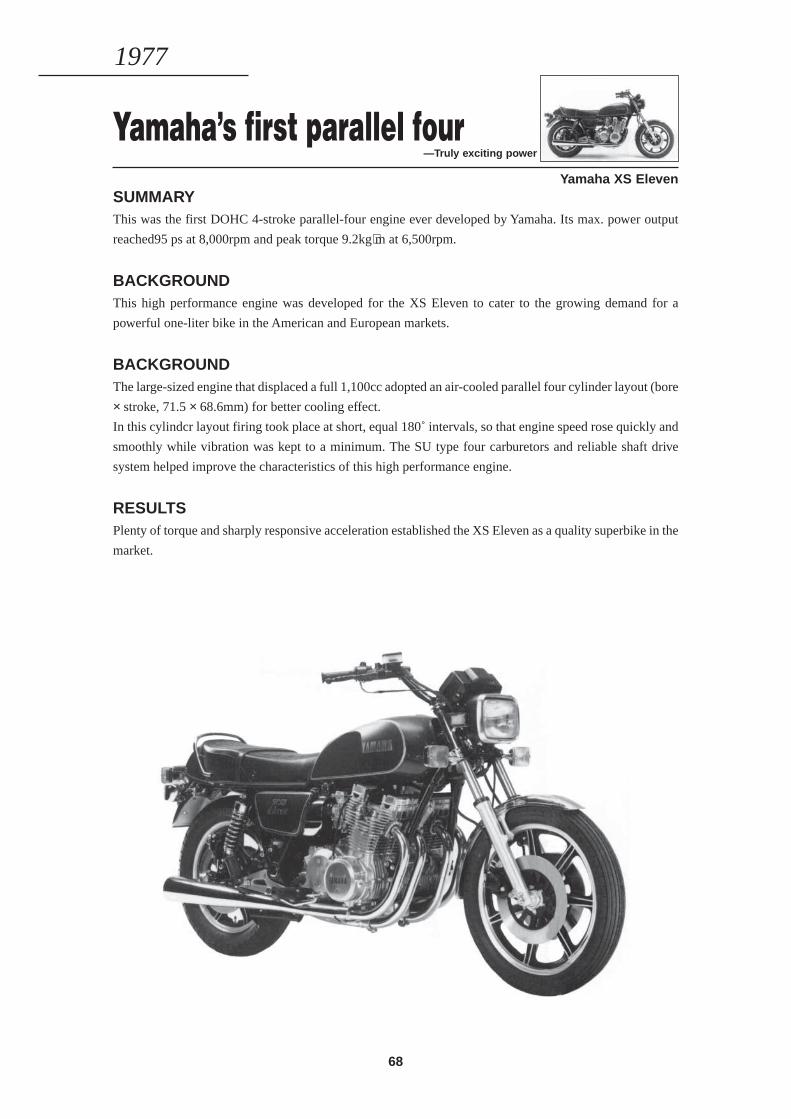
68
Yamaha’s first parallel four—Truly exciting power
Yamaha XS ElevenSUMMARYThis was the first DOHC 4-stroke parallel-four engine ever developed by Yamaha. Its max. power output
reached95 ps at 8,000rpm and peak torque 9.2kg⋅m at 6,500rpm.
BACKGROUNDThis high performance engine was developed for the XS Eleven to cater to the growing demand for a
powerful one-liter bike in the American and European markets.
BACKGROUNDThe large-sized engine that displaced a full 1,100cc adopted an air-cooled parallel four cylinder layout (bore
× stroke, 71.5 × 68.6mm) for better cooling effect.
In this cylindcr layout firing took place at short, equal 180˚ intervals, so that engine speed rose quickly and
smoothly while vibration was kept to a minimum. The SU type four carburetors and reliable shaft drive
system helped improve the characteristics of this high performance engine.
RESULTSPlenty of torque and sharply responsive acceleration established the XS Eleven as a quality superbike in the
market.
1977
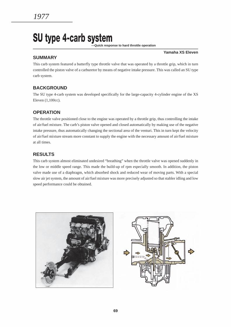
69
SU type 4-carb system—Quick response to hard throttle operation
Yamaha XS ElevenSUMMARYThis carb system featured a butterfly type throttle valve that was operated by a throttle grip, which in turn
controlled the piston valve of a carburetor by means of negative intake pressure. This was called an SU type
carb system.
BACKGROUNDThe SU type 4-carb system was developed specifically for the large-capacity 4-cylinder engine of the XS
Eleven (1,100cc).
OPERATIONThe throttle valve positioned close to the engine was operated by a throttle grip, thus controlling the intake
of air/fuel mixture. The carb’s piston valve opened and closed automatically by making use of the negative
intake pressure, thus automatically changing the sectional area of the venturi. This in turn kept the velocity
of air/fuel mixture stream more constant to supply the engine with the necessary amount of air/fuel mixture
at all times.
RESULTSThis carb system almost eliminated undesired “breathing” when the throttle valve was opened suddenly in
the low or middle speed range. This made the build-up of rpm especially smooth. In addition, the piston
valve made use of a diaphragm, which absorbed shock and reduced wear of moving parts. With a special
slow air jet system, the amount of air/fuel mixture was more precisely adjusted so that stabler idling and low
speed performance could be obtained.
1977

70
Oilbath type drive chain—Virtually maintenance-free characteristics
Yamaha Scooter Passol S50SUMMARYThe chain was encased in a sealed aluminum alloy case where the chain was constantly submerged in oil for
very effective lubrication.
BACKGROUNDThe Yamaha Passol was developed as a vehicle for women, and in that way succeeded in creating an entirely
new market. One of the important design points of this model was to make it look as non-mechanical as
possible. To also make this model as maintenance free as possible, the drive chain was designed in a com-
pletely sealed oilbath system.
CONSTRUCTIONThe drive chain was kept in oil in the completely sealed aluminum alloy case, so that very effective lubrica-
tion could be obtained, while resulting in less stretching of the chain. The system also included an automatic
tensioner that kept the chain adjusted to the proper tension.
RESULTSThis system not only gave the bike a nicer look, but also made it cleaner, and virtually maintenance-free.
1977
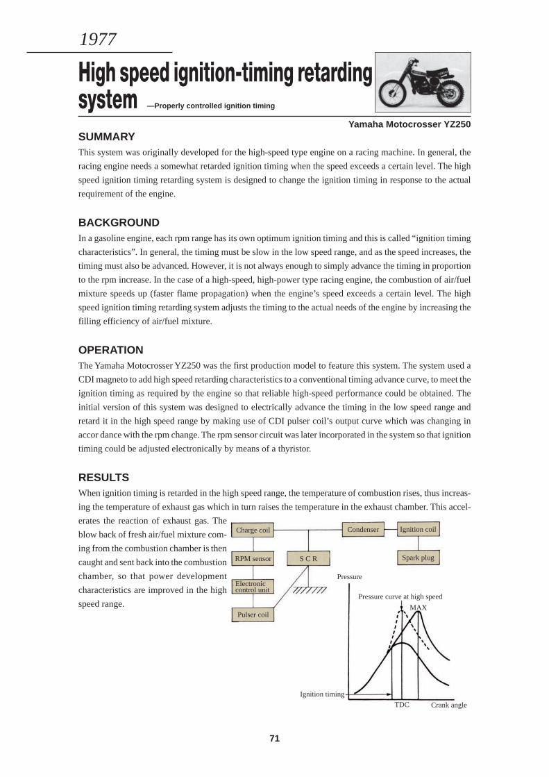
71
High speed ignition-timing retardingsystem —Properly controlled ignition timing
Yamaha Motocrosser YZ250SUMMARYThis system was originally developed for the high-speed type engine on a racing machine. In general, the
racing engine needs a somewhat retarded ignition timing when the speed exceeds a certain level. The high
speed ignition timing retarding system is designed to change the ignition timing in response to the actual
requirement of the engine.
BACKGROUNDIn a gasoline engine, each rpm range has its own optimum ignition timing and this is called “ignition timing
characteristics”. In general, the timing must be slow in the low speed range, and as the speed increases, the
timing must also be advanced. However, it is not always enough to simply advance the timing in proportion
to the rpm increase. In the case of a high-speed, high-power type racing engine, the combustion of air/fuel
mixture speeds up (faster flame propagation) when the engine’s speed exceeds a certain level. The high
speed ignition timing retarding system adjusts the timing to the actual needs of the engine by increasing the
filling efficiency of air/fuel mixture.
OPERATIONThe Yamaha Motocrosser YZ250 was the first production model to feature this system. The system used a
CDI magneto to add high speed retarding characteristics to a conventional timing advance curve, to meet the
ignition timing as required by the engine so that reliable high-speed performance could be obtained. The
initial version of this system was designed to electrically advance the timing in the low speed range and
retard it in the high speed range by making use of CDI pulser coil’s output curve which was changing in
accor dance with the rpm change. The rpm sensor circuit was later incorporated in the system so that ignition
timing could be adjusted electronically by means of a thyristor.
RESULTSWhen ignition timing is retarded in the high speed range, the temperature of combustion rises, thus increas-
ing the temperature of exhaust gas which in turn raises the temperature in the exhaust chamber. This accel-
erates the reaction of exhaust gas. The
blow back of fresh air/fuel mixture com-
ing from the combustion chamber is then
caught and sent back into the combustion
chamber, so that power development
characteristics are improved in the high
speed range.
1977
Pressure
Pressure curve at high speed
MAX
Ignition timing
TDC Crank angle
Charge coil
RPM sensor
Electroniccontrol unit
Pulser coil
S C R
Condenser Ignition coil
Spark plug
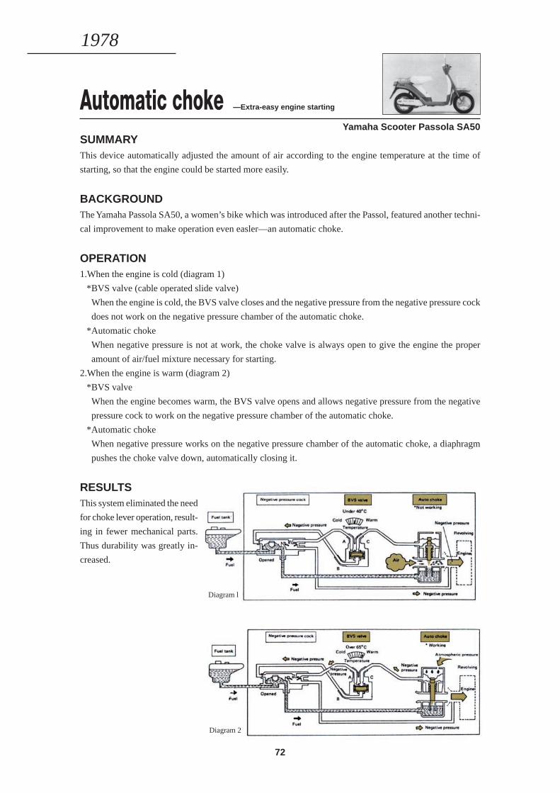
72
Automatic choke —Extra-easy engine starting
Yamaha Scooter Passola SA50SUMMARYThis device automatically adjusted the amount of air according to the engine temperature at the time of
starting, so that the engine could be started more easily.
BACKGROUNDThe Yamaha Passola SA50, a women’s bike which was introduced after the Passol, featured another techni-
cal improvement to make operation even easler—an automatic choke.
OPERATION1.When the engine is cold (diagram 1)
*BVS valve (cable operated slide valve)
When the engine is cold, the BVS valve closes and the negative pressure from the negative pressure cock
does not work on the negative pressure chamber of the automatic choke.
*Automatic choke
When negative pressure is not at work, the choke valve is always open to give the engine the proper
amount of air/fuel mixture necessary for starting.
2.When the engine is warm (diagram 2)
*BVS valve
When the engine becomes warm, the BVS valve opens and allows negative pressure from the negative
pressure cock to work on the negative pressure chamber of the automatic choke.
*Automatic choke
When negative pressure works on the negative pressure chamber of the automatic choke, a diaphragm
pushes the choke valve down, automatically closing it.
RESULTSThis system eliminated the need
for choke lever operation, result-
ing in fewer mechanical parts.
Thus durability was greatly in-
creased.
1978
Diagram l
Diagram 2
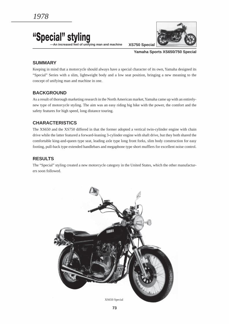
73
“Special” styling—An increased feel of unifying man and machine
Yamaha Sports XS650/750 Special
SUMMARYKeeping in mind that a motorcycle should always have a special character of its own, Yamaha designed its
“Special” Series with a slim, lightweight body and a low seat position, bringing a new meaning to the
concept of unifying man and machine in one.
BACKGROUNDAs a result of thorough marketing research in the North American market, Yamaha came up with an entirely-
new type of motorcycle styling. The aim was an easy riding big bike with the power, the comfort and the
safety features for high speed, long distance touring.
CHARACTERISTICSThe XS650 and the XS750 differed in that the former adopted a vertical twin-cylinder engine with chain
drive while the latter featured a forward-leaning 3-cylinder engine with shaft drive, but they both shared the
comfortable king-and-queen type seat, leading axle type long front forks, slim body construction for easy
footing, pull-back type extended handlebars and megaphone type short mufflers for excellent noise control.
RESULTSThe “Special” styling created a new motorcycle category in the United States, which the other manufactur-
ers soon followed.
1978
XS750 Special
XS650 Special
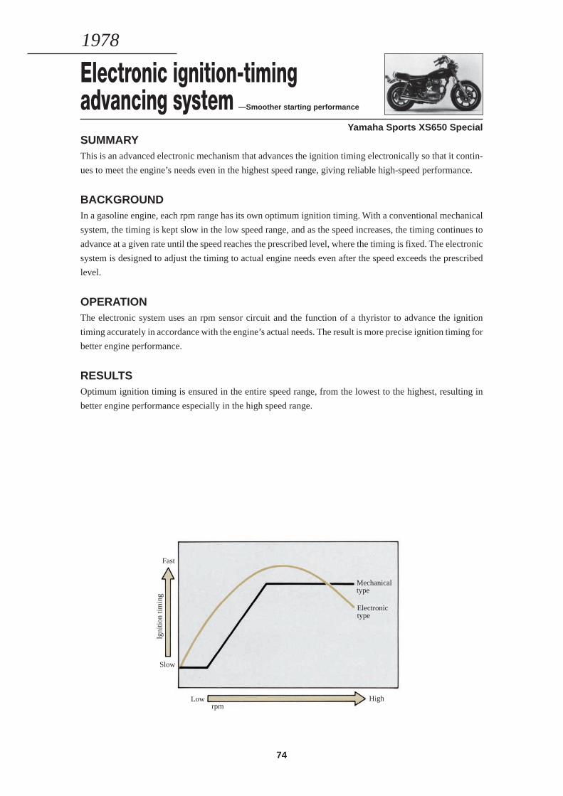
74
Electronic ignition-timingadvancing system —Smoother starting performance
Yamaha Sports XS650 SpecialSUMMARYThis is an advanced electronic mechanism that advances the ignition timing electronically so that it contin-
ues to meet the engine’s needs even in the highest speed range, giving reliable high-speed performance.
BACKGROUNDIn a gasoline engine, each rpm range has its own optimum ignition timing. With a conventional mechanical
system, the timing is kept slow in the low speed range, and as the speed increases, the timing continues to
advance at a given rate until the speed reaches the prescribed level, where the timing is fixed. The electronic
system is designed to adjust the timing to actual engine needs even after the speed exceeds the prescribed
level.
OPERATIONThe electronic system uses an rpm sensor circuit and the function of a thyristor to advance the ignition
timing accurately in accordance with the engine’s actual needs. The result is more precise ignition timing for
better engine performance.
RESULTSOptimum ignition timing is ensured in the entire speed range, from the lowest to the highest, resulting in
better engine performance especially in the high speed range.
1978
Fast
Igni
tion
timin
g
Slow
Mechanicaltype
Electronictype
HighLowrpm
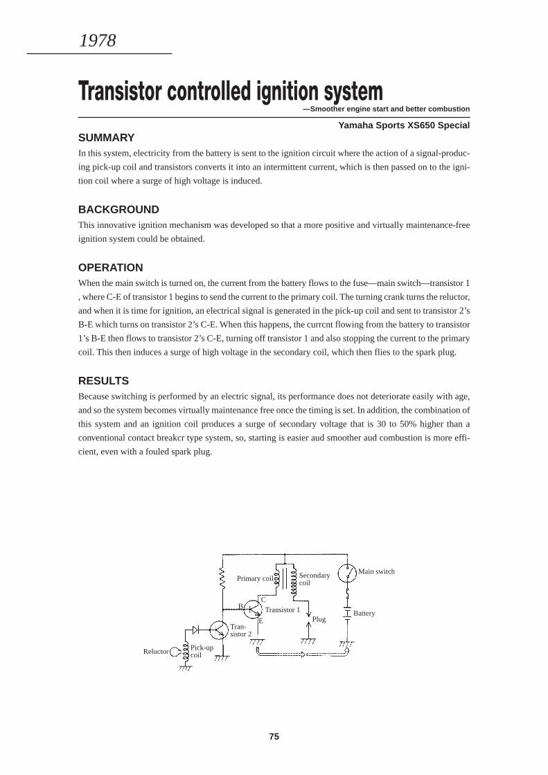
75
Transistor controlled ignition system—Smoother engine start and better combustion
Yamaha Sports XS650 SpecialSUMMARYIn this system, electricity from the battery is sent to the ignition circuit where the action of a signal-produc-
ing pick-up coil and transistors converts it into an intermittent current, which is then passed on to the igni-
tion coil where a surge of high voltage is induced.
BACKGROUNDThis innovative ignition mechanism was developed so that a more positive and virtually maintenance-free
ignition system could be obtained.
OPERATIONWhen the main switch is turned on, the current from the battery flows to the fuse—main switch—transistor 1
, where C-E of transistor 1 begins to send the current to the primary coil. The turning crank turns the reluctor,
and when it is time for ignition, an electrical signal is generated in the pick-up coil and sent to transistor 2’s
B-E which turns on transistor 2’s C-E. When this happens, the currcnt flowing from the battery to transistor
1’s B-E then flows to transistor 2’s C-E, turning off transistor 1 and also stopping the current to the primary
coil. This then induces a surge of high voltage in the secondary coil, which then flies to the spark plug.
RESULTSBecause switching is performed by an electric signal, its performance does not deteriorate easily with age,
and so the system becomes virtually maintenance free once the timing is set. In addition, the combination of
this system and an ignition coil produces a surge of secondary voltage that is 30 to 50% higher than a
conventional contact breakcr type system, so, starting is easier aud smoother aud combustion is more effi-
cient, even with a fouled spark plug.
1978
Reluctor Pick-upcoil
Primary coil
Tran-sistor 2
Secondarycoil
Main switch
PlugBattery
BC
E
Transistor 1
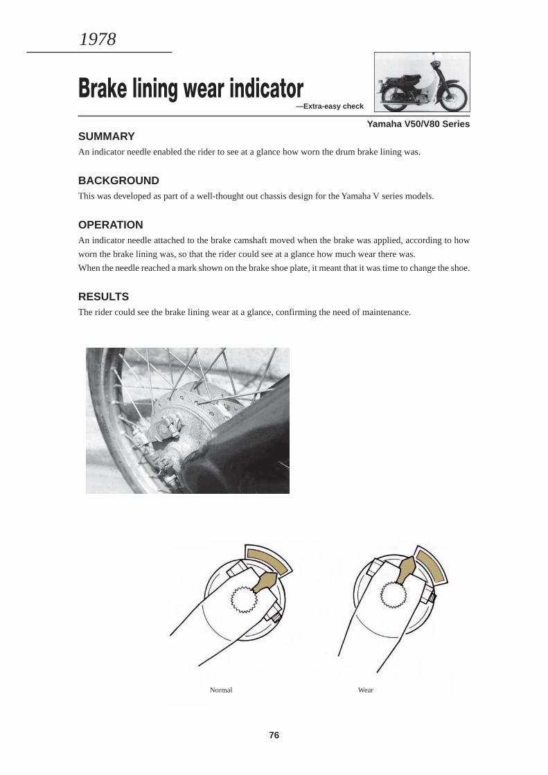
76
Brake lining wear indicator—Extra-easy check
Yamaha V50/V80 SeriesSUMMARYAn indicator needle enabled the rider to see at a glance how worn the drum brake lining was.
BACKGROUNDThis was developed as part of a well-thought out chassis design for the Yamaha V series models.
OPERATIONAn indicator needle attached to the brake camshaft moved when the brake was applied, according to how
worn the brake lining was, so that the rider could see at a glance how much wear there was.
When the needle reached a mark shown on the brake shoe plate, it meant that it was time to change the shoe.
RESULTSThe rider could see the brake lining wear at a glance, confirming the need of maintenance.
1978
Normal Wear
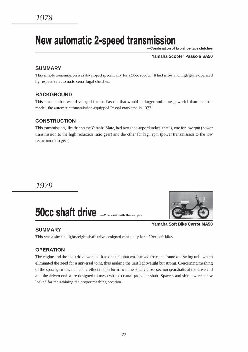
77
New automatic 2-speed transmission—Combination of two shoe-type clutches
Yamaha Scooter Passola SA50
SUMMARYThis simple transmission was developed specifically for a 50cc scooter. It had a low and high gears operated
by respective automatic centrifugal clutches.
BACKGROUNDThis transmission was developed for the Passola that would be larger and more powerful than its sister
model, the automatic transmission-equipped Passol marketed in 1977.
CONSTRUCTIONThis transmission, like that on the Yamaha Mate, had two shoe-type clutches, that is, one for low rpm (power
transmission to the high reduction ratio gear) and the other for high rpm (power transmission to the low
reduction ratio gear).
1978
50cc shaft drive —One unit with the engine
Yamaha Soft Bike Carrot MA50SUMMARYThis was a simple, lightweight shaft drive designed especially for a 50cc soft bike.
OPERATIONThe engine and the shaft drive were built as one unit that was hanged from the frame as a swing unit, which
eliminated the need for a universal joint, thus making the unit lightweight but strong. Concerning meshing
of the spiral gears, which could effect the performance, the square cross section gearshafts at the drive end
and the driven end were designed to mesh with a central propeller shaft. Spacers and shims were screw
locked for maintaining the proper meshing position.
1979
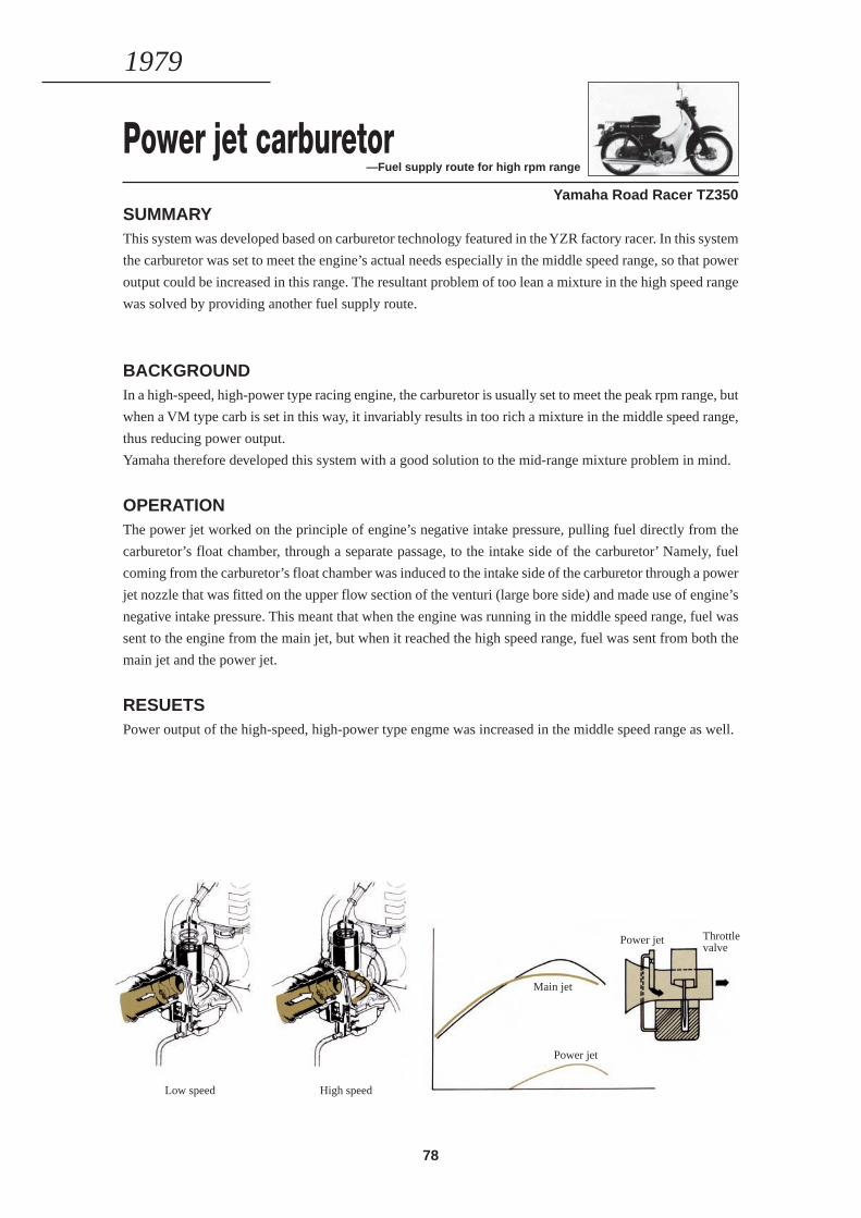
78
Power jet carburetor—Fuel supply route for high rpm range
Yamaha Road Racer TZ350SUMMARYThis system was developed based on carburetor technology featured in the YZR factory racer. In this system
the carburetor was set to meet the engine’s actual needs especially in the middle speed range, so that power
output could be increased in this range. The resultant problem of too lean a mixture in the high speed range
was solved by providing another fuel supply route.
BACKGROUNDIn a high-speed, high-power type racing engine, the carburetor is usually set to meet the peak rpm range, but
when a VM type carb is set in this way, it invariably results in too rich a mixture in the middle speed range,
thus reducing power output.
Yamaha therefore developed this system with a good solution to the mid-range mixture problem in mind.
OPERATIONThe power jet worked on the principle of engine’s negative intake pressure, pulling fuel directly from the
carburetor’s float chamber, through a separate passage, to the intake side of the carburetor’ Namely, fuel
coming from the carburetor’s float chamber was induced to the intake side of the carburetor through a power
jet nozzle that was fitted on the upper flow section of the venturi (large bore side) and made use of engine’s
negative intake pressure. This meant that when the engine was running in the middle speed range, fuel was
sent to the engine from the main jet, but when it reached the high speed range, fuel was sent from both the
main jet and the power jet.
RESUETSPower output of the high-speed, high-power type engme was increased in the middle speed range as well.
1979
Low speed High speed
Main jet
Power jet
Power jet Throttlevalve

79
1980—1984
LEADING THE AGEOF INTEGRATEDTECHNOLOGY
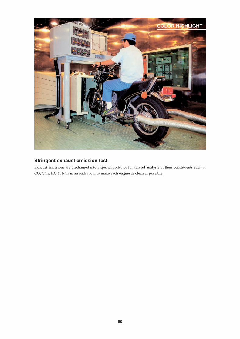
80
COLOR HIGHLIGHT
Stringent exhaust emission testExhaust emissions are discharged into a special collector for careful analysis of their constituents such as
CO, CO2, HC & NOX in an endeavour to make each engine as clean as possible.
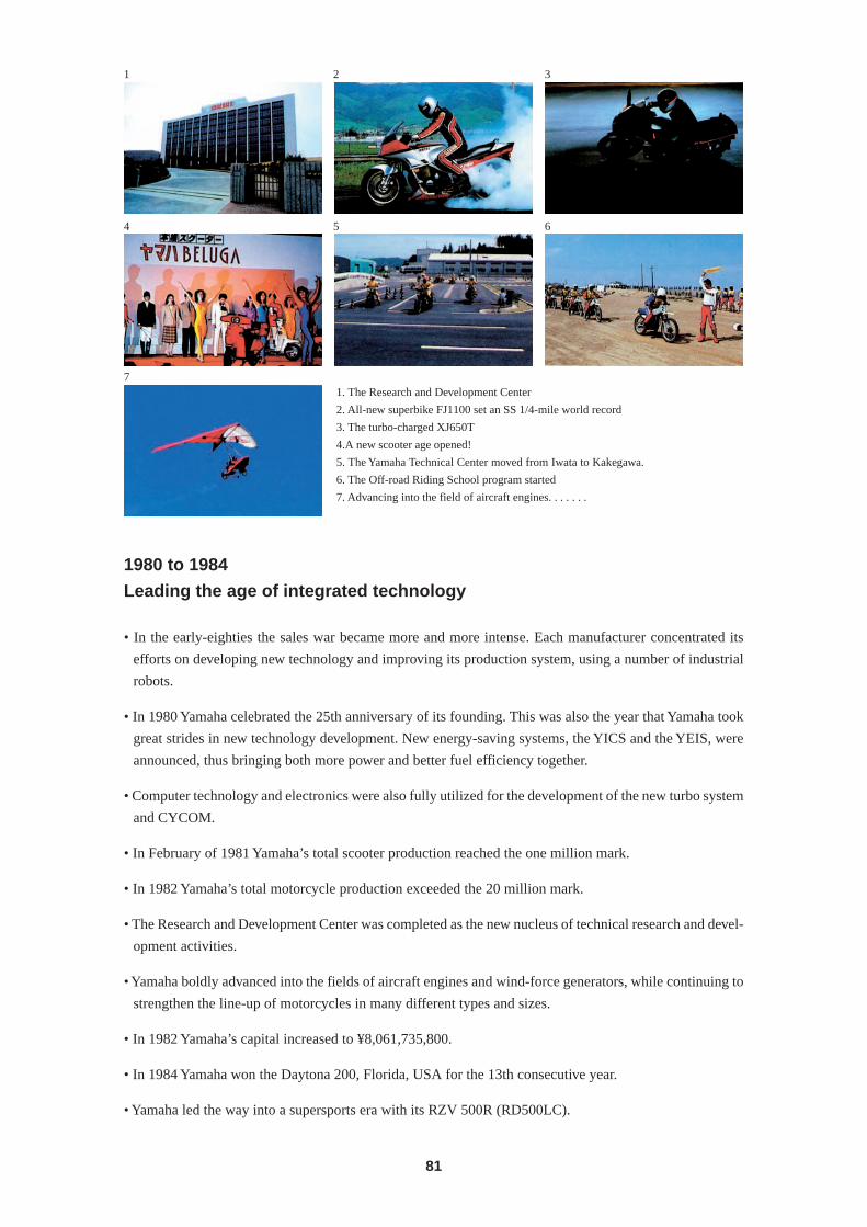
81
1 2 3
4 5 6
71. The Research and Development Center
2. All-new superbike FJ1100 set an SS 1/4-mile world record
3. The turbo-charged XJ650T
4.A new scooter age opened!
5. The Yamaha Technical Center moved from Iwata to Kakegawa.
6. The Off-road Riding School program started
7. Advancing into the field of aircraft engines. . . . . . .
1980 to 1984
Leading the age of integrated technology
• In the early-eighties the sales war became more and more intense. Each manufacturer concentrated its
efforts on developing new technology and improving its production system, using a number of industrial
robots.
• In 1980 Yamaha celebrated the 25th anniversary of its founding. This was also the year that Yamaha took
great strides in new technology development. New energy-saving systems, the YICS and the YEIS, were
announced, thus bringing both more power and better fuel efficiency together.
• Computer technology and electronics were also fully utilized for the development of the new turbo system
and CYCOM.
• In February of 1981 Yamaha’s total scooter production reached the one million mark.
• In 1982 Yamaha’s total motorcycle production exceeded the 20 million mark.
• The Research and Development Center was completed as the new nucleus of technical research and devel-
opment activities.
• Yamaha boldly advanced into the fields of aircraft engines and wind-force generators, while continuing to
strengthen the line-up of motorcycles in many different types and sizes.
• In 1982 Yamaha’s capital increased to ¥8,061,735,800.
• In 1984 Yamaha won the Daytona 200, Florida, USA for the 13th consecutive year.
• Yamaha led the way into a supersports era with its RZV 500R (RD500LC).
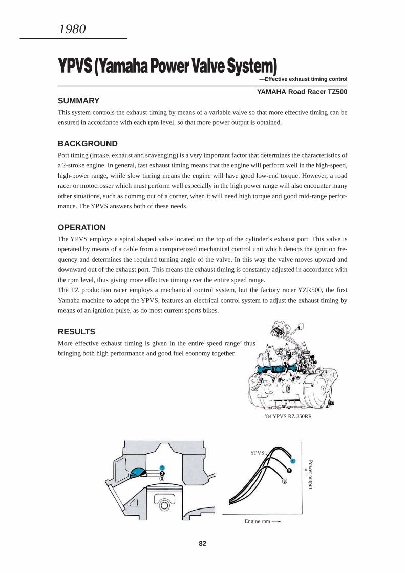
82
YPVS (Yamaha Power Valve System)—Effective exhaust timing control
YAMAHA Road Racer TZ500SUMMARYThis system controls the exhaust timing by means of a variable valve so that more effective timing can be
ensured in accordance with each rpm level, so that more power output is obtained.
BACKGROUNDPort timing (intake, exhaust and scavenging) is a very important factor that determines the characteristics of
a 2-stroke engine. In general, fast exhaust timing means that the engine will perform well in the high-speed,
high-power range, while slow timing means the engine will have good low-end torque. However, a road
racer or motocrosser which must perform well especially in the high power range will also encounter many
other situations, such as commg out of a corner, when it will need high torque and good mid-range perfor-
mance. The YPVS answers both of these needs.
OPERATIONThe YPVS employs a spiral shaped valve located on the top of the cylinder’s exhaust port. This valve is
operated by means of a cable from a computerized mechanical control unit which detects the ignition fre-
quency and determines the required turning angle of the valve. In this way the valve moves upward and
downward out of the exhaust port. This means the exhaust timing is constantly adjusted in accordance with
the rpm level, thus giving more effectrve timing over the entire speed range.
The TZ production racer employs a mechanical control system, but the factory racer YZR500, the first
Yamaha machine to adopt the YPVS, features an electrical control system to adjust the exhaust timing by
means of an ignition pulse, as do most current sports bikes.
RESULTSMore effective exhaust timing is given in the entire speed range’ thus
bringing both high performance and good fuel economy together.
1980
’84 YPVS RZ 250RR
Engine rpm
YPVS
Power output
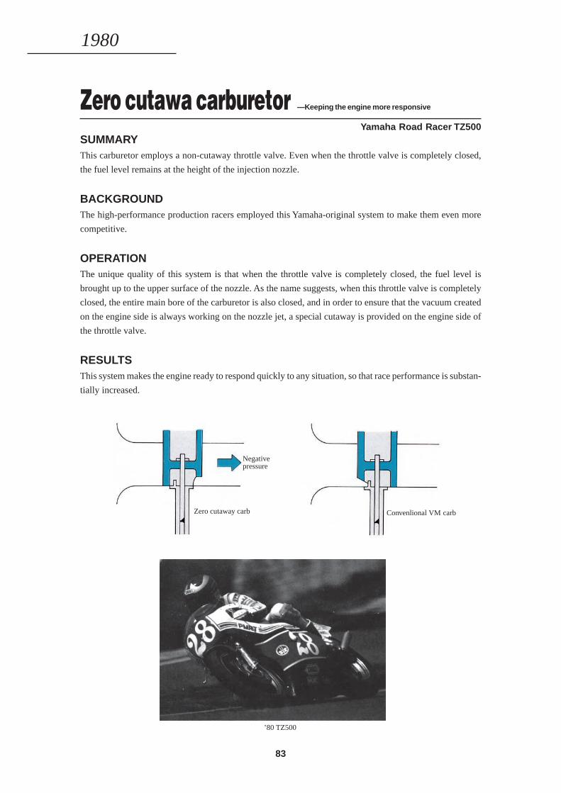
83
Zero cutawa carburetor —Keeping the engine more responsive
Yamaha Road Racer TZ500SUMMARYThis carburetor employs a non-cutaway throttle valve. Even when the throttle valve is completely closed,
the fuel level remains at the height of the injection nozzle.
BACKGROUNDThe high-performance production racers employed this Yamaha-original system to make them even more
competitive.
OPERATIONThe unique quality of this system is that when the throttle valve is completely closed, the fuel level is
brought up to the upper surface of the nozzle. As the name suggests, when this throttle valve is completely
closed, the entire main bore of the carburetor is also closed, and in order to ensure that the vacuum created
on the engine side is always working on the nozzle jet, a special cutaway is provided on the engine side of
the throttle valve.
RESULTSThis system makes the engine ready to respond quickly to any situation, so that race performance is substan-
tially increased.
1980
’80 TZ500
Negativepressure
Zero cutaway carb Convenlional VM carb
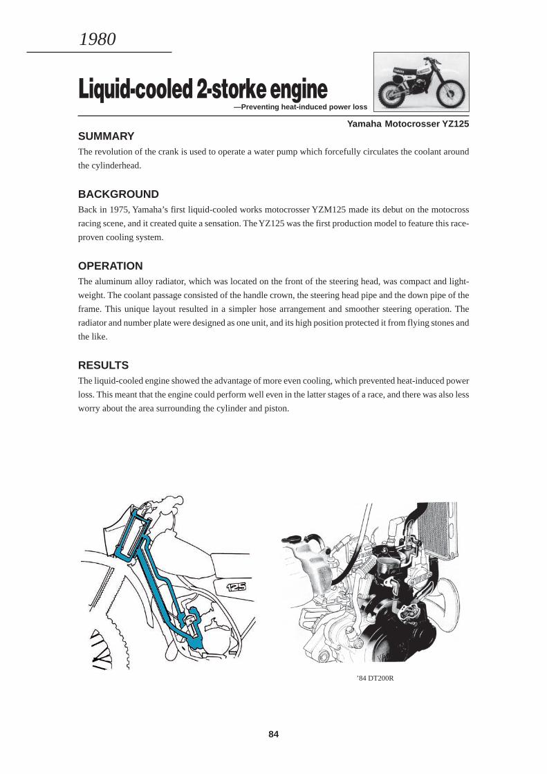
84
Liquid-cooled 2-storke engine—Preventing heat-induced power loss
Yamaha Motocrosser YZ125SUMMARYThe revolution of the crank is used to operate a water pump which forcefully circulates the coolant around
the cylinderhead.
BACKGROUNDBack in 1975, Yamaha’s first liquid-cooled works motocrosser YZM125 made its debut on the motocross
racing scene, and it created quite a sensation. The YZ125 was the first production model to feature this race-
proven cooling system.
OPERATIONThe aluminum alloy radiator, which was located on the front of the steering head, was compact and light-
weight. The coolant passage consisted of the handle crown, the steering head pipe and the down pipe of the
frame. This unique layout resulted in a simpler hose arrangement and smoother steering operation. The
radiator and number plate were designed as one unit, and its high position protected it from flying stones and
the like.
RESULTSThe liquid-cooled engine showed the advantage of more even cooling, which prevented heat-induced power
loss. This meant that the engine could perform well even in the latter stages of a race, and there was also less
worry about the area surrounding the cylinder and piston.
1980
’84 DT200R
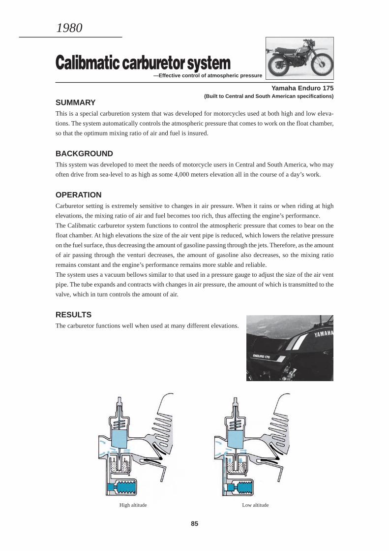
85
Calibmatic carburetor system—Effective control of atmospheric pressure
SUMMARYThis is a special carburetion system that was developed for motorcycles used at both high and low eleva-
tions. The system automatically controls the atmospheric pressure that comes to work on the float chamber,
so that the optimum mixing ratio of air and fuel is insured.
BACKGROUNDThis system was developed to meet the needs of motorcycle users in Central and South America, who may
often drive from sea-level to as high as some 4,000 meters elevation all in the course of a day’s work.
OPERATIONCarburetor setting is extremely sensitive to changes in air pressure. When it rains or when riding at high
elevations, the mixing ratio of air and fuel becomes too rich, thus affecting the engine’s performance.
The Calibmatic carburetor system functions to control the atmospheric pressure that comes to bear on the
float chamber. At high elevations the size of the air vent pipe is reduced, which lowers the relative pressure
on the fuel surface, thus decreasing the amount of gasoline passing through the jets. Therefore, as the amount
of air passing through the venturi decreases, the amount of gasoline also decreases, so the mixing ratio
remains constant and the engine’s performance remains more stable and reliable.
The system uses a vacuum bellows similar to that used in a pressure gauge to adjust the size of the air vent
pipe. The tube expands and contracts with changes in air pressure, the amount of which is transmitted to the
valve, which in turn controls the amount of air.
RESULTSThe carburetor functions well when used at many different elevations.
1980
Yamaha Enduro 175 (Built to Central and South American specifications)
High altitude Low altitude
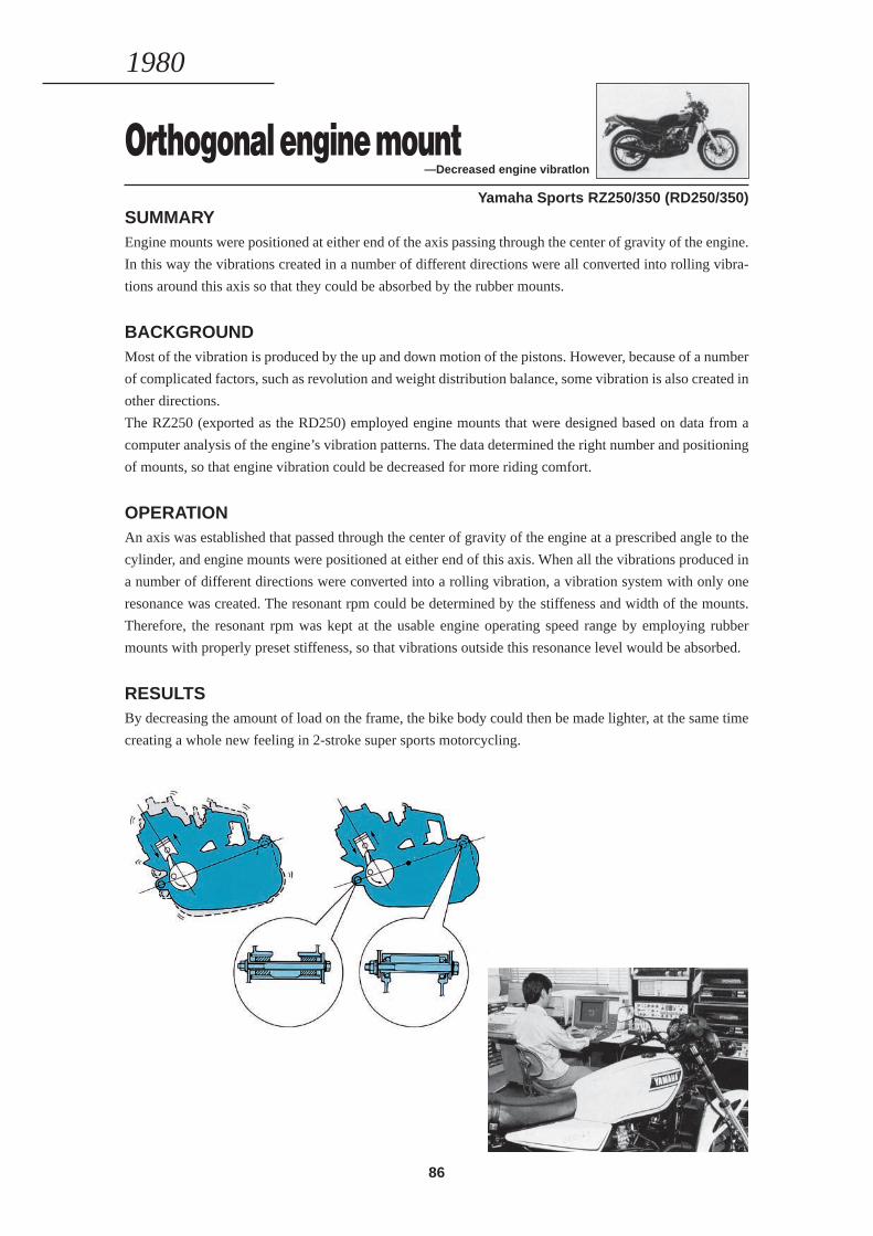
86
Orthogonal engine mount—Decreased engine vibratlon
Yamaha Sports RZ250/350 (RD250/350)SUMMARYEngine mounts were positioned at either end of the axis passing through the center of gravity of the engine.
In this way the vibrations created in a number of different directions were all converted into rolling vibra-
tions around this axis so that they could be absorbed by the rubber mounts.
BACKGROUNDMost of the vibration is produced by the up and down motion of the pistons. However, because of a number
of complicated factors, such as revolution and weight distribution balance, some vibration is also created in
other directions.
The RZ250 (exported as the RD250) employed engine mounts that were designed based on data from a
computer analysis of the engine’s vibration patterns. The data determined the right number and positioning
of mounts, so that engine vibration could be decreased for more riding comfort.
OPERATIONAn axis was established that passed through the center of gravity of the engine at a prescribed angle to the
cylinder, and engine mounts were positioned at either end of this axis. When all the vibrations produced in
a number of different directions were converted into a rolling vibration, a vibration system with only one
resonance was created. The resonant rpm could be determined by the stiffeness and width of the mounts.
Therefore, the resonant rpm was kept at the usable engine operating speed range by employing rubber
mounts with properly preset stiffeness, so that vibrations outside this resonance level would be absorbed.
RESULTSBy decreasing the amount of load on the frame, the bike body could then be made lighter, at the same time
creating a whole new feeling in 2-stroke super sports motorcycling.
1980
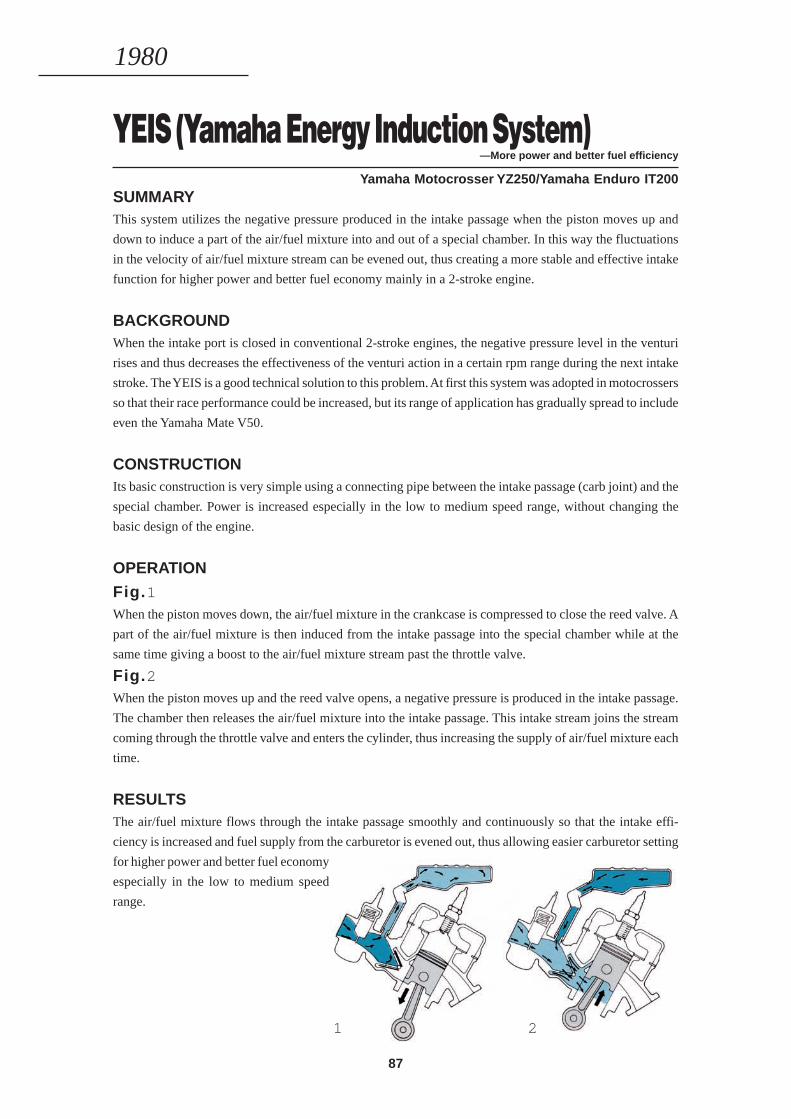
87
YEIS (Yamaha Energy Induction System)—More power and better fuel efficiency
Yamaha Motocrosser YZ250/Yamaha Enduro IT200SUMMARYThis system utilizes the negative pressure produced in the intake passage when the piston moves up and
down to induce a part of the air/fuel mixture into and out of a special chamber. In this way the fluctuations
in the velocity of air/fuel mixture stream can be evened out, thus creating a more stable and effective intake
function for higher power and better fuel economy mainly in a 2-stroke engine.
BACKGROUNDWhen the intake port is closed in conventional 2-stroke engines, the negative pressure level in the venturi
rises and thus decreases the effectiveness of the venturi action in a certain rpm range during the next intake
stroke. The YEIS is a good technical solution to this problem. At first this system was adopted in motocrossers
so that their race performance could be increased, but its range of application has gradually spread to include
even the Yamaha Mate V50.
CONSTRUCTIONIts basic construction is very simple using a connecting pipe between the intake passage (carb joint) and the
special chamber. Power is increased especially in the low to medium speed range, without changing the
basic design of the engine.
OPERATION
Fig.1When the piston moves down, the air/fuel mixture in the crankcase is compressed to close the reed valve. A
part of the air/fuel mixture is then induced from the intake passage into the special chamber while at the
same time giving a boost to the air/fuel mixture stream past the throttle valve.
Fig.2When the piston moves up and the reed valve opens, a negative pressure is produced in the intake passage.
The chamber then releases the air/fuel mixture into the intake passage. This intake stream joins the stream
coming through the throttle valve and enters the cylinder, thus increasing the supply of air/fuel mixture each
time.
RESULTSThe air/fuel mixture flows through the intake passage smoothly and continuously so that the intake effi-
ciency is increased and fuel supply from the carburetor is evened out, thus allowing easier carburetor setting
for higher power and better fuel economy
especially in the low to medium speed
range.
1980
1 2
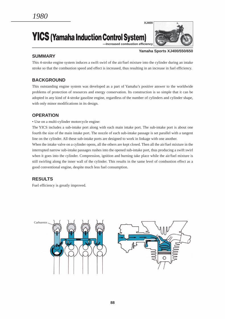
88
YICS (Yamaha Induction Control System)—Increased combustion efficiency
Yamaha Sports XJ400/550/650SUMMARYThis 4-stroke engine system induces a swift swirl of the air/fuel mixture into the cylinder during an intake
stroke so that the combustion speed and effect is increased, thus resulting in an increase in fuel efficiency.
BACKGROUNDThis outstanding engine system was developed as a part of Yamaha’s positive answer to the worldwide
problems of protection of resources and energy conservation. Its construction is so simple that it can be
adopted in any kind of 4-stroke gasoline engine, regardless of the number of cylinders and cylinder shape,
with only minor modifications in its design.
OPERATION• Use on a multi-cylinder motorcycle engine:
The YICS includes a sub-intake port along with each main intake port. The sub-intake port is about one
fourth the size of the main intake port. The nozzle of each sub-intake passage is set parallel with a tangent
line on the cylinder. All these sub-intake ports are designed to work in linkage with one another.
When the intake valve on a cylinder opens, all the others are kept closed. Then all the air/fuel mixture in the
interrupted narrow sub-intake passages rushes into the opened sub-intake port, thus producing a swift swirl
when it goes into the cylinder. Compression, ignition and burning take place while the air/fuel mixture is
still swirling along the inner wall of the cylinder. This results in the same level of combustion effect as a
good conventional engine, despite much less fuel consumption.
RESULTSFuel efficiency is greatly improved.
1980
Carburetor
XJ400
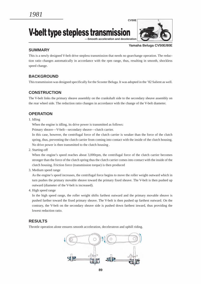
89
V-belt type stepless transmission—Smooth acceleratlon and deceleration
Yamaha Beluga CV50E/80ESUMMARYThis is a newly designed V-belt drive stepless transmission that needs no gearchange operation. The reduc-
tion ratio changes automatically in accordance with the rpm range, thus, resulting in smooth, shockless
speed change.
BACKGROUNDThis transmission was designed specifically for the Scooter Beluga. It was adopted in the ’82 Salient as well.
CONSTRUCTIONThe V-belt links the primary sheave assembly on the crankshaft side to the secondary sheave assembly on
the rear wheel side. The reduction ratio changes in accordance with the change of the V-belt diameter.
OPERATION1. Idling
When the engine is idling, its drive power is transmitted as follows:
Primary sheave—V-belt—secondary sheave—clutch carrier.
In this case, however, the centrifugal force of the clutch carrier is weaker than the force of the clutch
spring, thus, preventing the clutch carrier from coming into contact with the inside of the clutch housing.
No drive power is then transmitted to the clutch housing .
2. Starting-off
When the engine’s speed reaches about 3,000rpm, the centrifugal force of the clutch carrier becomes
stronger than the force of the clutch spring thus the clutch carrier comes into contact with the inside of the
clutch housing. Friction force (transmission torque) is then produced
3. Medium speed range
As the engine’s speed increases, the centrifugal force begins to move the roller weight outward which in
turn pushes the primary movable sheave toward the primary fixed sheave. The V-belt is then pushed up
outward (diameter of the V-belt is increased).
4. High speed range
In the high speed range, the roller weight shifts farthest outward and the primary movable sheave is
pushed farther toward the fixed primary sheave. The V-belt is then pushed up farthest outward. On the
contrary, the V-belt on the secondary sheave side is pushed down farthest inward, thus providing the
lowest reduction ratio.
RESULTSThrottle operation alone ensures smooth acceleration, deceleratron and uphill riding.
1981CV50E
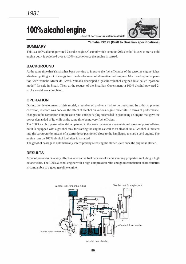
90
100% alcohol engine—Use of corrosion-resistant materials
Yamaha RX125 (Built to Brazilian specifications)SUMMARYThis is a 100% alcohol powered 2-stroke engine. Gasohol which contains 20% alcohol is used to start a cold
engine but it is switched over to 100% alcohol once the engine is started.
BACKGROUNDAt the same time that Yamaha has been working to improve the fuel efficiency of the gasoline engine, it has
also been putting a lot of energy into the development of alternative fuel engines. Much earlier, in coopera-
tion with Yamaha Motor do Brasil, Yamaha developed a gasoline/alcohol engined bike called “gasohol
model” for sale in Brazil. Then, at the request of the Brazilian Government, a 100% alcohol powered 2-
stroke model was completed.
OPERATIONDuring the development of this model, a number of problems had to be overcome. In order to prevent
corrosion, research was done on the effect of alcohol on various engine materials. In terms of performance,
changes in the carburetor, compression ratio and spark plug succeeded in producing an engine that gave the
power demanded of it, while at the same time being very fuel efficient.
The 100% alcohol powered model is operated in the same manner as a conventional gasoline powered bike,
but it is equipped with a gasohol tank for starting the engine as well as an alcohol tank. Gasohol is induced
into the carburetor by means of a starter lever positioned close to the handlegrip to start a cold engine. The
engine runs on 100% alcohol fuel after it is started.
The gasohol passage is automatically interrupted by releasing the starter lever once the engine is started.
RESULTSAlcohol proves to be a very effective alternative fuel because of its outstanding properties including a high
octane value. The 100% alcohol engine with a high compression ratio and good combustion characteristics
is comparable to a good gasoline engine.
1981
Alcohol tank for normal riding
Starter lever auto return
Gasohol tank for engine start
Gasohol float chamber
Alcohol float chamber
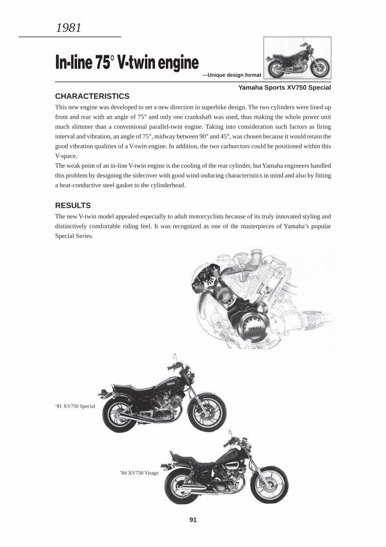
91
In-line 75° V-twin engine—Unique design format
Yamaha Sports XV750 SpecialCHARACTERISTICSThis new engine was developed to set a new direction in superbike design. The two cylinders were lined up
front and rear with an angle of 75° and only one crankshaft was used, thus making the whole power unit
much slimmer than a conventional parallel-twin engine. Taking into consideration such factors as firing
interval and vibration, an angle of 75°, midway between 90° and 45°, was chosen because it would retain the
good vibration qualities of a V-twin engine. In addition, the two carburctors could be positioned within this
V-space.
The weak point of an in-line V-twin engine is the cooling of the rear cylinder, but Yamaha engineers handled
this problem by designing the sidecover with good wind-inducing characteristics in mind and also by fitting
a heat-conductive steel gasket to the cylinderhead.
RESULTSThe new V-twin model appealed especially to adult motorcyclists because of its truly innovated styling and
distinctively comfortable riding feel. It was recognized as one of the masterpieces of Yamaha’s popular
Special Series.
1981
’84 XV750 Virago
’81 XV750 Special
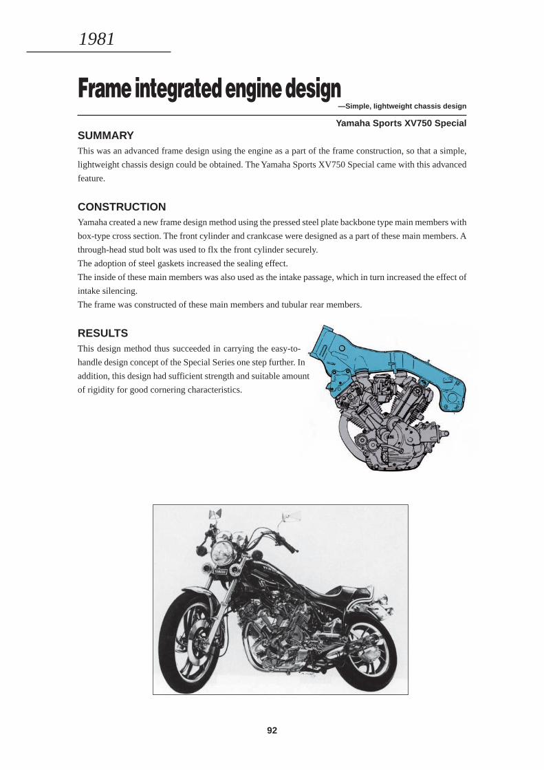
92
Frame integrated engine design—Simple, Iightweight chassis design
Yamaha Sports XV750 SpecialSUMMARYThis was an advanced frame design using the engine as a part of the frame construction, so that a simple,
lightweight chassis design could be obtained. The Yamaha Sports XV750 Special came with this advanced
feature.
CONSTRUCTIONYamaha created a new frame design method using the pressed steel plate backbone type main members with
box-type cross section. The front cylinder and crankcase were designed as a part of these main members. A
through-head stud bolt was used to flx the front cylinder securely.
The adoption of steel gaskets increased the sealing effect.
The inside of these main members was also used as the intake passage, which in turn increased the effect of
intake silencing.
The frame was constructed of these main members and tubular rear members.
RESULTSThis design method thus succeeded in carrying the easy-to-
handle design concept of the Special Series one step further. In
addition, this design had sufficient strength and suitable amount
of rigidity for good cornering characteristics.
1981
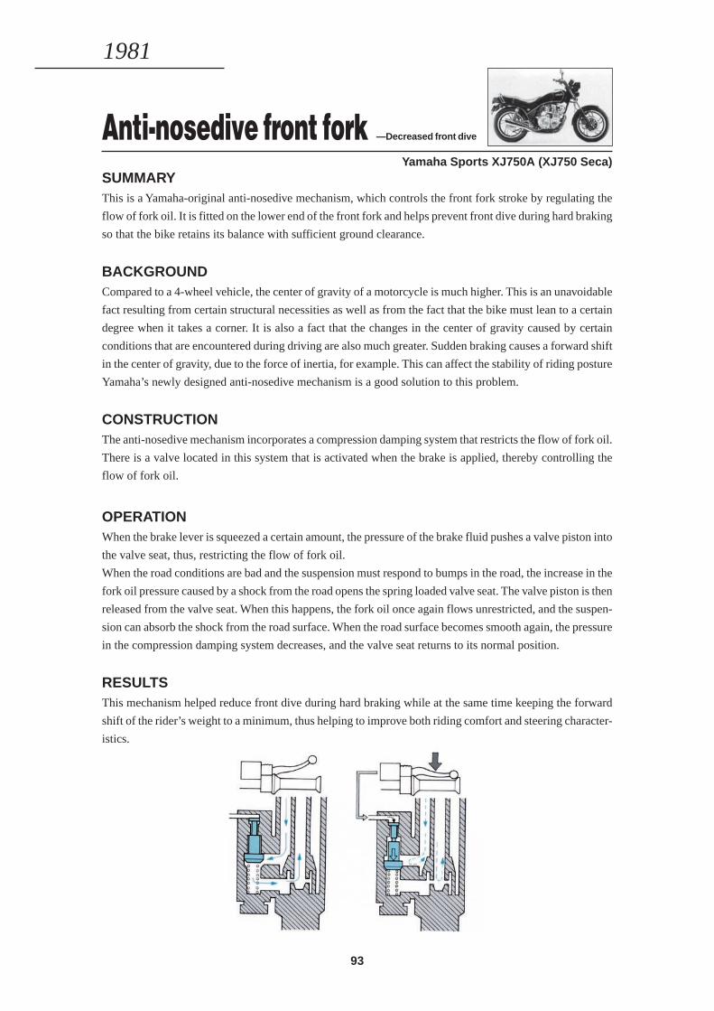
93
Anti-nosedive front fork —Decreased front dive
Yamaha Sports XJ750A (XJ750 Seca)SUMMARYThis is a Yamaha-original anti-nosedive mechanism, which controls the front fork stroke by regulating the
flow of fork oil. It is fitted on the lower end of the front fork and helps prevent front dive during hard braking
so that the bike retains its balance with sufficient ground clearance.
BACKGROUNDCompared to a 4-wheel vehicle, the center of gravity of a motorcycle is much higher. This is an unavoidable
fact resulting from certain structural necessities as well as from the fact that the bike must lean to a certain
degree when it takes a corner. It is also a fact that the changes in the center of gravity caused by certain
conditions that are encountered during driving are also much greater. Sudden braking causes a forward shift
in the center of gravity, due to the force of inertia, for example. This can affect the stability of riding posture
Yamaha’s newly designed anti-nosedive mechanism is a good solution to this problem.
CONSTRUCTIONThe anti-nosedive mechanism incorporates a compression damping system that restricts the flow of fork oil.
There is a valve located in this system that is activated when the brake is applied, thereby controlling the
flow of fork oil.
OPERATIONWhen the brake lever is squeezed a certain amount, the pressure of the brake fluid pushes a valve piston into
the valve seat, thus, restricting the flow of fork oil.
When the road conditions are bad and the suspension must respond to bumps in the road, the increase in the
fork oil pressure caused by a shock from the road opens the spring loaded valve seat. The valve piston is then
released from the valve seat. When this happens, the fork oil once again flows unrestricted, and the suspen-
sion can absorb the shock from the road surface. When the road surface becomes smooth again, the pressure
in the compression damping system decreases, and the valve seat returns to its normal position.
RESULTSThis mechanism helped reduce front dive during hard braking while at the same time keeping the forward
shift of the rider’s weight to a minimum, thus helping to improve both riding comfort and steering character-
istics.
1981

94
Computerized monitor system —Easier machine check
Yamaha Sports XJ750A (XJ750 Seca)SUMMARYThis system utilizes a micro-computer to monitor the position of the sidestand, the amount of brake fluid,
lubrication oil, battery fluid, fuel level, and the headlight and tail/brake lamp functions, and clearly display
all these information on the instrument panel, thus enabling the rider to see them at a glance. The above
model became the world’s first motorcycle to feature this system.
BACKGROUNDThe system represents Yarnaha’s positive and strong policy of developing new technology and new quality
products, clearly saying— “This is Yamaha’s idea of how a motorcycle should be built in the ’80s”.
CONSTRUCTION The system consists of sensors that monitor the motorcycle’s vital functions, and by means of a micro-
computer and an integrated cir-cuit board, analyzes and displays the information on a liquid crystal display
(LCD) panel.
OPERATIONWhen the main switch is turned “ON”, raw
information from the sensors is fed to the mi-
cro-computer which analyzes it and displays
the results on the panel. If there is some ir-
regularity that requires the rider’s attention, a
warning lamp goes on.
Also, while driving, the rider can press the
check button at any time to put the system into
function. The display time for one function on
the check list is 0.7 sec.
RESULTSThe machine can be checked out automatically before or during riding.
1981
Head light
Points for monitoring
Fuel level
Brake fluid
Tail/brake lamp
Battery fluid
Lubrication oil
Position of the sidestand
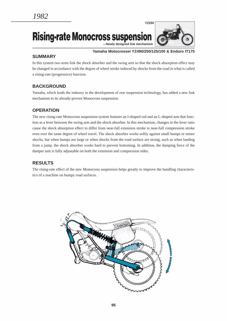
95
Rising-rate Monocross suspension—Newly designed link mechanism
Yamaha Motocrosser YZ490/250/125/100 & Enduro IT175SUMMARYIn this system two arms link the shock absorber and the swing arm so that the shock absorption effect may
be changed in accordance with the degree of wheel stroke induced by shocks from the road in what is called
a rising-rate (progressive) function.
BACKGROUNDYamaha, which leads the industry in the development of rear suspension technology, has added a new link
mechanism to its already-proven Monocross suspension.
OPERATIONThe new rising-rate Monocross suspension system features an I-shaped rod and an L-shaped arm that func-
tion as a lever between the swing arm and the shock absorber. In this mechanism, changes in the lever ratio
cause the shock absorption effect to differ from near-full extension stroke to near-full compression stroke
even over the same degree of wheel travel. The shock absorber works softly against small bumps or minor
shocks, but when bumps are large or when shocks from the road surface are strong, such as when landing
from a jump, the shock absorber works hard to prevent bottoming. In addition, the damping force of the
damper unit is fully adjustable on both the extension and compression sides.
RESULTSThe rising-rate effect of the new Monocross suspension helps greatly to improve the handling characteris-
tics of a machine on bumpy road surfaces.
1982YZ250

96
Turbo system —Yamaha’s new total system
Yamaha Sports XJ650TSUMMARYThe turbo system makes use of the exhaust energy to turn a turbine which in turn drives a compressor to
supply more air into the engine to produce more power.
The unique quality of Yamaha’s turbo system is that it employs a conventional carburetor system instead of
a special fuel injection system while it makes the high performance turbo charger even more effective by
combining it with several other technological achievements, thus creating a new “total system”.
BACKGROUNDYamaha’s history in turbo technology goes all the way back to the Toyota 7 which had its first test run in July
of 1970. The Toyota 7 was the first turbocharged car built in Japan, having a 5-liter V-8 engine equipped
with a Yamaha designed twin turbo system. The XJ650T was introduced as Yamaha’s first production turbo
model, using a conventional carburetor system based on Yamaha’s long proven turbo technology.
CONSTRUCTIONCompleted into one integrated system are: the proven reed valve induction system and energy-saving YICS
along with the unique turbo charger, pressurized carburetor system and vacuum type electronic governor
with knocking sensor.
OPERATION* At low speeds: Normal aspiration. Of course, this includes the proven YICS function that ensures good
fuel economy without sacrificing drivability
* At high speeds: As the exhaust energy increases, the turbo charger begins to work, supplying more air into
the engine to produce more power, which in turn gets more performance out of the fuel that is consumed.
* Acceleration: When the throttle is snapped open, the reed valve opens without delay to ensure that the
engine gets all the air it needs. This means quick engine response and a smooth lead into the turbo charger
function.
RESULTSBetter fuel economy, quicker engine response and outstanding power development characteristics are en-
sured over the entire speed range. In addition, the conventional carburetor system increases the mainte-
nance-free characteristics of this turbo system.
1982
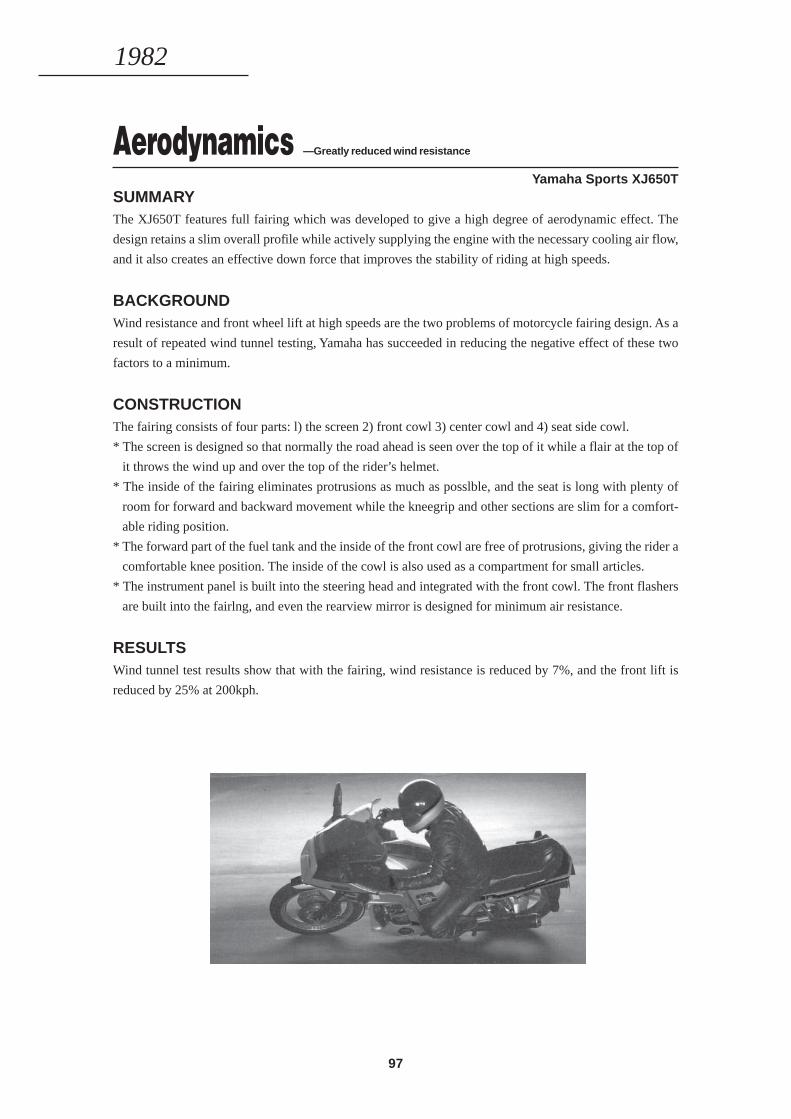
97
Aerodynamics —Greatly reduced wind resistance
Yamaha Sports XJ650TSUMMARYThe XJ650T features full fairing which was developed to give a high degree of aerodynamic effect. The
design retains a slim overall profile while actively supplying the engine with the necessary cooling air flow,
and it also creates an effective down force that improves the stability of riding at high speeds.
BACKGROUNDWind resistance and front wheel lift at high speeds are the two problems of motorcycle fairing design. As a
result of repeated wind tunnel testing, Yamaha has succeeded in reducing the negative effect of these two
factors to a minimum.
CONSTRUCTIONThe fairing consists of four parts: l) the screen 2) front cowl 3) center cowl and 4) seat side cowl.
* The screen is designed so that normally the road ahead is seen over the top of it while a flair at the top of
it throws the wind up and over the top of the rider’s helmet.
* The inside of the fairing eliminates protrusions as much as posslble, and the seat is long with plenty of
room for forward and backward movement while the kneegrip and other sections are slim for a comfort-
able riding position.
* The forward part of the fuel tank and the inside of the front cowl are free of protrusions, giving the rider a
comfortable knee position. The inside of the cowl is also used as a compartment for small articles.
* The instrument panel is built into the steering head and integrated with the front cowl. The front flashers
are built into the fairlng, and even the rearview mirror is designed for minimum air resistance.
RESULTSWind tunnel test results show that with the fairing, wind resistance is reduced by 7%, and the front lift is
reduced by 25% at 200kph.
1982
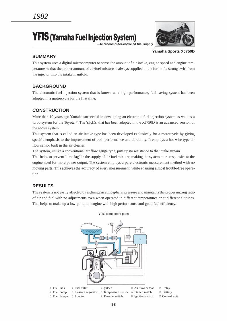
98
YFIS (Yamaha Fuel Injection System)—Microcomputer-cotrolled fuel supply
Yamaha Sports XJ750DSUMMARYThis system uses a digital microcomputer to sense the amount of air intake, engine speed and engine tem-
perature so that the proper amount of air/fuel mixture is always supplied in the form of a strong swirl from
the injector into the intake manifold.
BACKGROUNDThe electronic fuel injection system that is known as a high performance, fuel saving system has been
adopted in a motorcycle for the first time.
CONSTRUCTIONMore than 10 years ago Yamaha succeeded in developing an electronic fuel injection system as well as a
turbo system for the Toyota 7. The Y,F,I,S, that has been adopted in the XJ750D is an advanced version of
the above system.
This system that is called an air intake type has been developed exclusively for a motorcycle by giving
specific emphasis to the improvement of both performance and durability. It employs a hot wire type air
flow sensor built in the air cleaner.
The system, unlike a conventional air flow gauge type, puts up no resistance to the intake stream.
This helps to prevent “time lag” in the supply of air-fuel mixture, making the system more responsive to the
engine need for more power output. The system employs a pure electronic measurement method with no
moving parts. This achieves the accuracy of every measurement, while ensuring almost trouble-free opera-
tion.
RESULTSThe system is not easily affected by a change in atmospheric pressure and maintains the proper mixing ratio
of air and fuel with no adjustments even when operated in different temperatures or at different altitudes.
This helps to make up a low-pollution engine with high performance and good fuel efficiency.
1982
YFIS component parts
1 Fuel tank2 Fuel pump3 Fuel damper
0 Air flow sensorA Starter switchB Ignition switch
7 pulser8 Temperature sensor9 Throttle switch
4 Fuel filter5 Pressure regulator6 Injector
C RelayD BatteryE Control unit
1
0
7
98
6
D
D
C
B
A
5
3
42
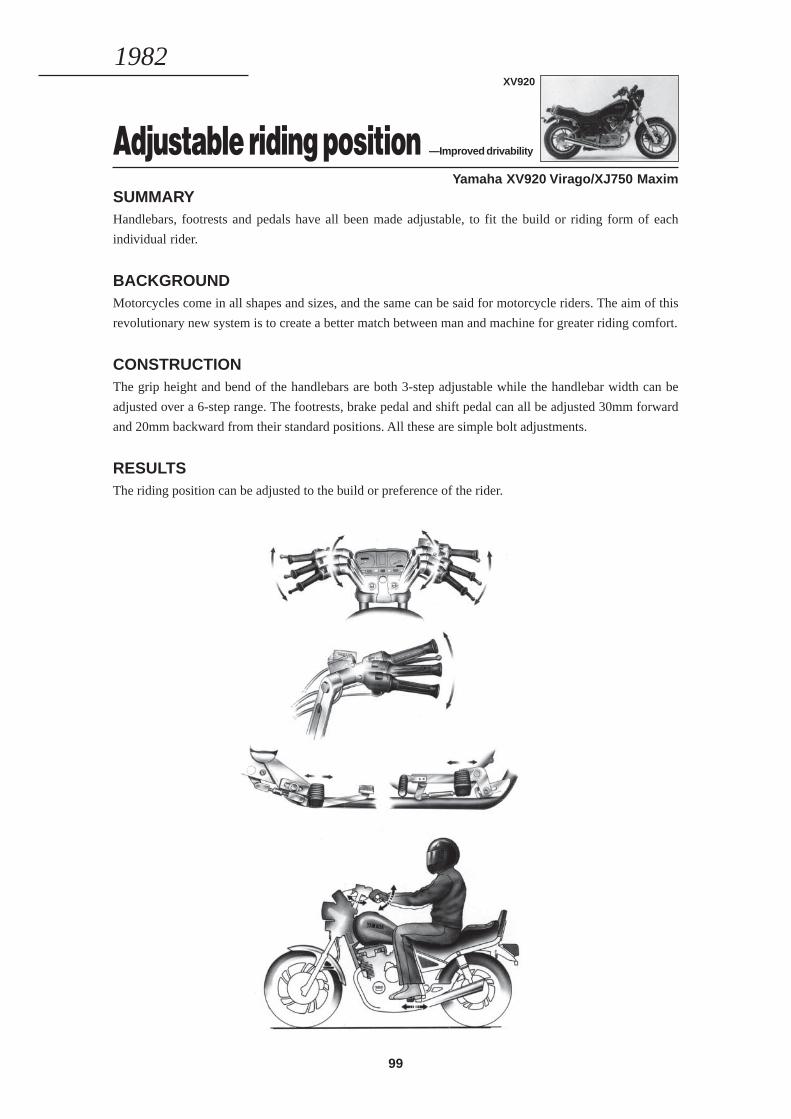
99
Adjustable riding position —Improved drivability
Yamaha XV920 Virago/XJ750 MaximSUMMARYHandlebars, footrests and pedals have all been made adjustable, to fit the build or riding form of each
individual rider.
BACKGROUNDMotorcycles come in all shapes and sizes, and the same can be said for motorcycle riders. The aim of this
revolutionary new system is to create a better match between man and machine for greater riding comfort.
CONSTRUCTIONThe grip height and bend of the handlebars are both 3-step adjustable while the handlebar width can be
adjusted over a 6-step range. The footrests, brake pedal and shift pedal can all be adjusted 30mm forward
and 20mm backward from their standard positions. All these are simple bolt adjustments.
RESULTSThe riding position can be adjusted to the build or preference of the rider.
1982XV920
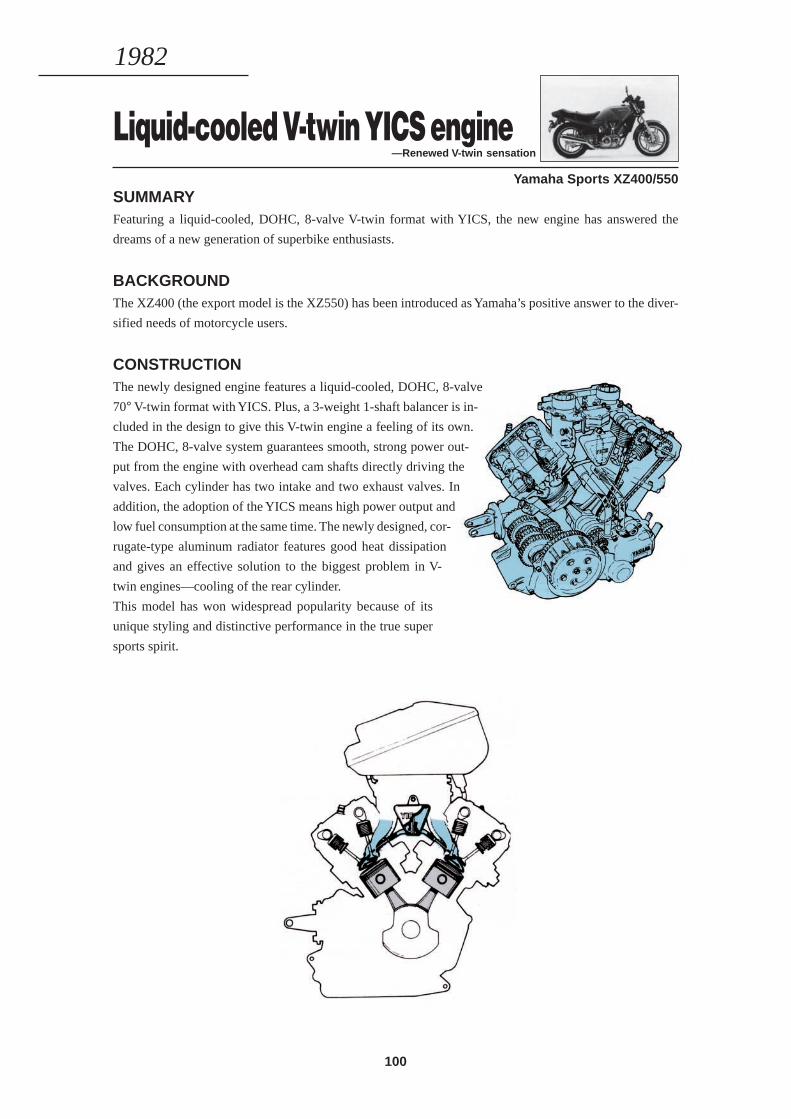
100
Liquid-cooled V-twin YICS engine—Renewed V-twin sensation
Yamaha Sports XZ400/550SUMMARYFeaturing a liquid-cooled, DOHC, 8-valve V-twin format with YICS, the new engine has answered the
dreams of a new generation of superbike enthusiasts.
BACKGROUNDThe XZ400 (the export model is the XZ550) has been introduced as Yamaha’s positive answer to the diver-
sified needs of motorcycle users.
CONSTRUCTIONThe newly designed engine features a liquid-cooled, DOHC, 8-valve
70° V-twin format with YICS. Plus, a 3-weight 1-shaft balancer is in-
cluded in the design to give this V-twin engine a feeling of its own.
The DOHC, 8-valve system guarantees smooth, strong power out-
put from the engine with overhead cam shafts directly driving the
valves. Each cylinder has two intake and two exhaust valves. In
addition, the adoption of the YICS means high power output and
low fuel consumption at the same time. The newly designed, cor-
rugate-type aluminum radiator features good heat dissipation
and gives an effective solution to the biggest problem in V-
twin engines—cooling of the rear cylinder.
This model has won widespread popularity because of its
unique styling and distinctive performance in the true super
sports spirit.
1982
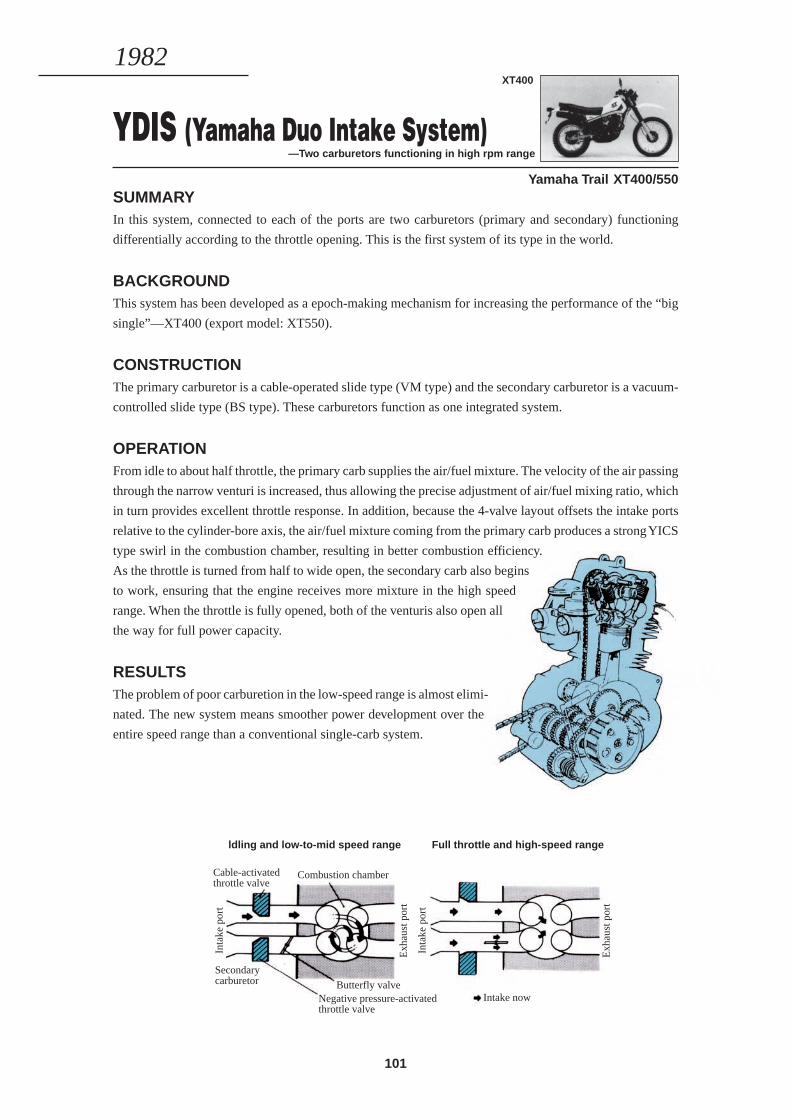
101
YDIS (Yamaha Duo Intake System)—Two carburetors functioning in high rpm range
Yamaha Trail XT400/550SUMMARYIn this system, connected to each of the ports are two carburetors (primary and secondary) functioning
differentially according to the throttle opening. This is the first system of its type in the world.
BACKGROUNDThis system has been developed as a epoch-making mechanism for increasing the performance of the “big
single”—XT400 (export model: XT550).
CONSTRUCTIONThe primary carburetor is a cable-operated slide type (VM type) and the secondary carburetor is a vacuum-
controlled slide type (BS type). These carburetors function as one integrated system.
OPERATIONFrom idle to about half throttle, the primary carb supplies the air/fuel mixture. The velocity of the air passing
through the narrow venturi is increased, thus allowing the precise adjustment of air/fuel mixing ratio, which
in turn provides excellent throttle response. In addition, because the 4-valve layout offsets the intake ports
relative to the cylinder-bore axis, the air/fuel mixture coming from the primary carb produces a strong YICS
type swirl in the combustion chamber, resulting in better combustion efficiency.
As the throttle is turned from half to wide open, the secondary carb also begins
to work, ensuring that the engine receives more mixture in the high speed
range. When the throttle is fully opened, both of the venturis also open all
the way for full power capacity.
RESULTSThe problem of poor carburetion in the low-speed range is almost elimi-
nated. The new system means smoother power development over the
entire speed range than a conventional single-carb system.
1982XT400
ldling and low-to-mid speed range Full throttle and high-speed range
Combustion chamber
Inta
ke p
ort
Secondarycarburetor Butterfly valve
Negative pressure-activatedthrottle valve
Exh
aust
por
t
Inta
ke p
ort
Exh
aust
por
t
Intake now
Cable-activatedthrottle valve
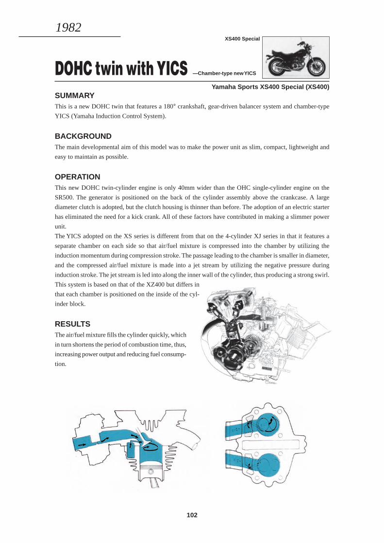
102
DOHC twin with YICS —Chamber-type new YICS
Yamaha Sports XS400 Special (XS400)SUMMARYThis is a new DOHC twin that features a 180° crankshaft, gear-driven balancer system and chamber-type
YICS (Yamaha Induction Control System).
BACKGROUNDThe main developmental aim of this model was to make the power unit as slim, compact, lightweight and
easy to maintain as possible.
OPERATIONThis new DOHC twin-cylinder engine is only 40mm wider than the OHC single-cylinder engine on the
SR500. The generator is positioned on the back of the cylinder assembly above the crankcase. A large
diameter clutch is adopted, but the clutch housing is thinner than before. The adoption of an electric starter
has eliminated the need for a kick crank. All of these factors have contributed in making a slimmer power
unit.
The YICS adopted on the XS series is different from that on the 4-cylinder XJ series in that it features a
separate chamber on each side so that air/fuel mixture is compressed into the chamber by utilizing the
induction momentum during compression stroke. The passage leading to the chamber is smaller in diameter,
and the compressed air/fuel mixture is made into a jet stream by utilizing the negative pressure during
induction stroke. The jet stream is led into along the inner wall of the cylinder, thus producing a strong swirl.
This system is based on that of the XZ400 but differs in
that each chamber is positioned on the inside of the cyl-
inder block.
RESULTSThe air/fuel mixture fills the cylinder quickly, which
in turn shortens the period of combustion time, thus,
increasing power output and reducing fuel consump-
tion.
1982XS400 Special
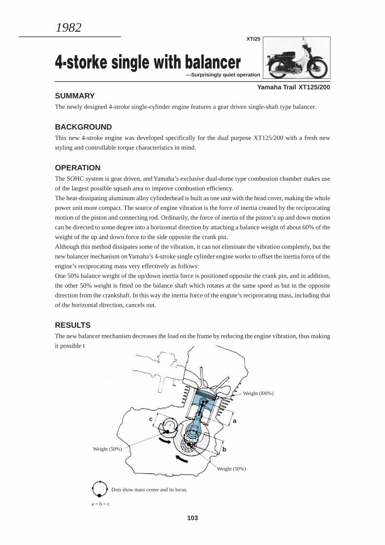
103
4-storke single with balancer—Surprisingly quiet operation
Yamaha Trail XT125/200SUMMARYThe newly designed 4-stroke single-cylinder engine features a gear driven single-shaft type balancer.
BACKGROUNDThis new 4-stroke engine was developed specifically for the dual purpose XT125/200 with a fresh new
styling and controllable torque characteristics in mind.
OPERATIONThe SOHC system is gear driven, and Yamaha’s exclusive dual-dome type combustion chamber makes use
of the largest possible squash area to improve combustion efficiency.
The heat-dissipating aluminum alloy cylinderhead is built as one unit with the head cover, making the whole
power unit more compact. The source of engine vibration is the force of inertia created by the reciprocating
motion of the piston and connecting rod. Ordinarily, the force of inertia of the piston’s up and down motion
can be directed to some degree into a horizontal direction by attaching a balance weight of about 60% of the
weight of the up and down force to the side opposite the crank pin.
Although this method dissipates some of the vibration, it can not eliminate the vibration completely, but the
new balancer mechanism on Yamaha’s 4-stroke single cylinder engine works to offset the inertia force of the
engine’s reciprocating mass very effectively as follows:
One 50% balance weight of the up/down inertia force is positioned opposite the crank pin, and in addition,
the other 50% weight is fitted on the balance shaft which rotates at the same speed as but in the opposite
direction from the crankshaft. In this way the inertia force of the engine’s reciprocating mass, including that
of the horizontal direction, cancels out.
RESULTSThe new balancer mechanism decreases the load on the frame by reducing the engine vibration, thus making
it possible to use a lightweight diamond-type frame.
1982XTI25
Weight (l00%)
Weight (50%)
Weight (50%)
Dots show mass center and its locus.
a = b = c
a
b
c
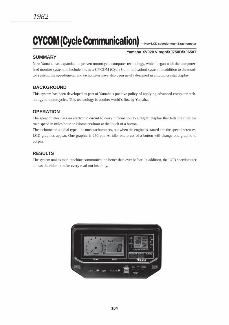
104
CYCOM (Cycle Communication) —New LCD speedometer & tachometer
Yamaha XV920 Virago/XJ750D/XJ650TSUMMARYNow Yamaha has expanded its proven motorcycle computer technology, which began with the computer-
ized monitor system, to include this new CYCOM (Cycle Communication) system. In addition to the moni-
tor system, the speedometer and tachometer have also been newly designed in a liquid crystal display.
BACKGROUNDThis system has been developed as part of Yamaha’s positive policy of applying advanced computer tech-
nology to motorcycles. This technology is another world’s first by Yamaha.
OPERATIONThe speedometer uses an electronic circuit to carry information to a digital display that tells the rider the
road speed in miles/hour or kilometers/hour at the touch of a button.
The tachometer is a dial type, like most tachometers, but when the engine is started and the speed increases,
LCD graphics appear. One graphic is 250rpm. At idle, one press of a button will change one graphic to
50rpm.
RESULTSThe system makes man-machine communication better than ever before. In addition, the LCD speedometer
allows the rider to make every read-out instantly.
1982
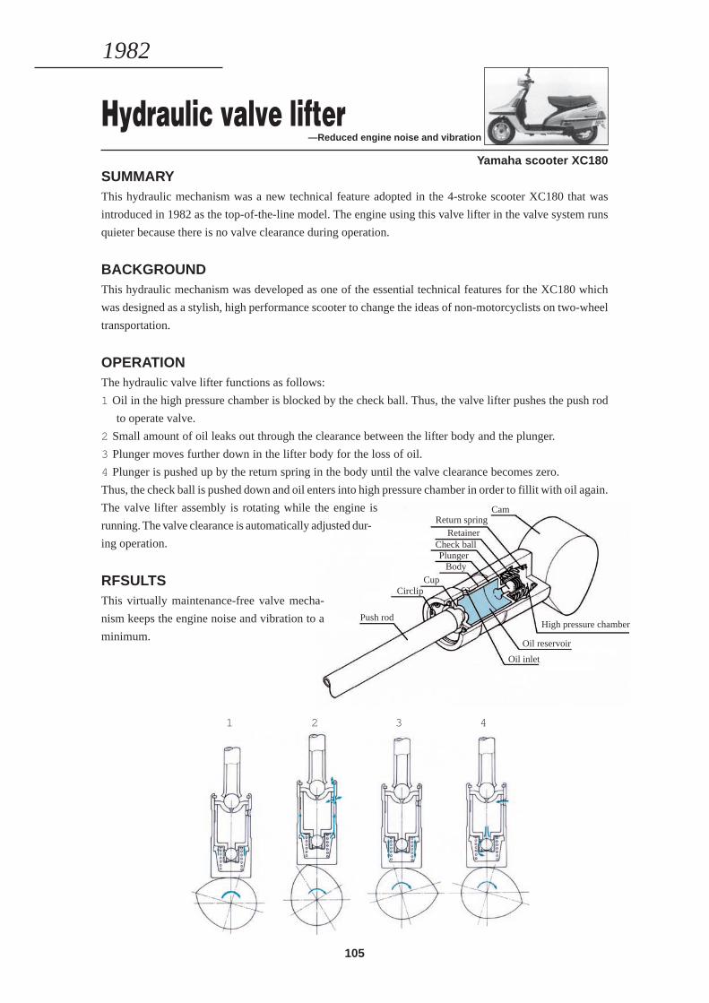
105
CamReturn spring
RetainerCheck ballPlunger
BodyCup
Circlip
Push rodHigh pressure chamber
Oil reservoir
Oil inlet
Hydraulic valve lifter—Reduced engine noise and vibration
Yamaha scooter XC180SUMMARYThis hydraulic mechanism was a new technical feature adopted in the 4-stroke scooter XC180 that was
introduced in 1982 as the top-of-the-line model. The engine using this valve lifter in the valve system runs
quieter because there is no valve clearance during operation.
BACKGROUNDThis hydraulic mechanism was developed as one of the essential technical features for the XC180 which
was designed as a stylish, high performance scooter to change the ideas of non-motorcyclists on two-wheel
transportation.
OPERATIONThe hydraulic valve lifter functions as follows:
1 Oil in the high pressure chamber is blocked by the check ball. Thus, the valve lifter pushes the push rod
to operate valve.
2 Small amount of oil leaks out through the clearance between the lifter body and the plunger.
3 Plunger moves further down in the lifter body for the loss of oil.
4 Plunger is pushed up by the return spring in the body until the valve clearance becomes zero.
Thus, the check ball is pushed down and oil enters into high pressure chamber in order to fillit with oil again.
The valve lifter assembly is rotating while the engine is
running. The valve clearance is automatically adjusted dur-
ing operation.
RFSULTSThis virtually maintenance-free valve mecha-
nism keeps the engine noise and vibration to a
minimum.
1982
1 2 3 4
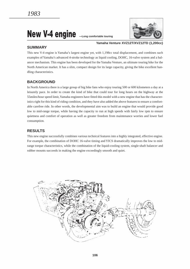
106
New V-4 engine —Long comfortable touring
Yamaha Venture XVZ12T/XVZ12TD (1,200cc)SUMMARYThis new V-4 engine is Yamaha’s largest engine yet, with 1,198cc total displacement, and combines such
examples of Yamaha’s advanced 4-stroke technology as liquid cooling, DOHC, 16-valve system and a bal-
ancer mechanism. This engine has been developed for the Yamaha Venture, an ultimate touring bike for the
North American market. It has a slim, compact design for its large capacity, giving the bike excellent han-
dling characteristics.
BACKGROUNDIn North America there is a large group of big bike fans who enjoy touring 500 or 600 kilometers a day at a
leisurely pace. In order to create the kind of bike that could tour for long hours on the highway at the
55miles/hour speed limit, Yamaha engineers have fitted this model with a new engine that has the character-
istics right for this kind of riding condition, and they have also added the above features to ensure a comfort-
able carefree ride. In other words, the developmental aim was to build an engine that would provide good
low to mid-range torque, while having the capacity to run at high speeds with fairly low rpm to ensure
quietness and comfort of operation as well as greater freedom from maintenance worries and lower fuel
consumption.
RESULTSThis new engine successfully combines various technical features into a highly integrated, effective engine.
For example, the combination of DOHC 16-valve timing and YICS dramatically improves the low to mid-
range torque characteristics, while the combination of the liquid-cooling system, single-shaft balancer and
rubber mounts succeeds in making the engine exceedingly smooth and quiet.
1983
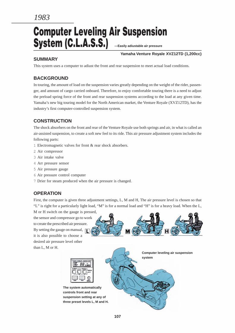
107
Computer Leveling Air SuspensionSystem (C.L.A.S.S.) —Easily adiustable air pressure
Yamaha Venture Royale XVZ12TD (1,200cc)SUMMARYThis system uses a computer to adiust the front and rear suspension to meet actual load conditions.
BACKGROUNDIn touring, the amount of load on the suspension varies greatly depending on the weight of the rider, passen-
ger, and amount of cargo carried onboard. Therefore, to enjoy comfortable touring there is a need to adjust
the preload spring force of the front and rear suspension systems according to the load at any given time.
Yamaha’s new big touring model for the North American market, the Venture Royale (XVZ12TD), has the
industry’s first computer-controlled suspension system.
CONSTRUCTIONThe shock absorbers on the front and rear of the Venture Royale use both springs and air, in what is called an
air-assisted suspension, to create a soft new feel to its ride. This air pressure adjustment system includes the
following parts:
1 Electromagnetic valves for front & rear shock absorbers.
2 Air compressor
3 Air intake valve
4 Arr pressure sensor
5 Air pressure gauge
6 Air pressure control computer
7 Drier for steam produced when the air pressure is changed.
OPERATIONFirst, the computer is given three adjustment settings, L, M and H, The air pressure level is chosen so that
“L” is right for a particularly light load, “M” is for a normal load and “H” is for a heavy load. When the L,
M or H switch on the gauge is pressed,
the sensor and compressor go to work
to create the prescribed air pressure.
By setting the gauge on manual,
it is also possible to choose a
desired air pressure level other
than L, M or H.
1983
Computer leveling air suspension
system
The system automatically
controls front and rear
suspension setting at any of
three preset levels L, M and H.
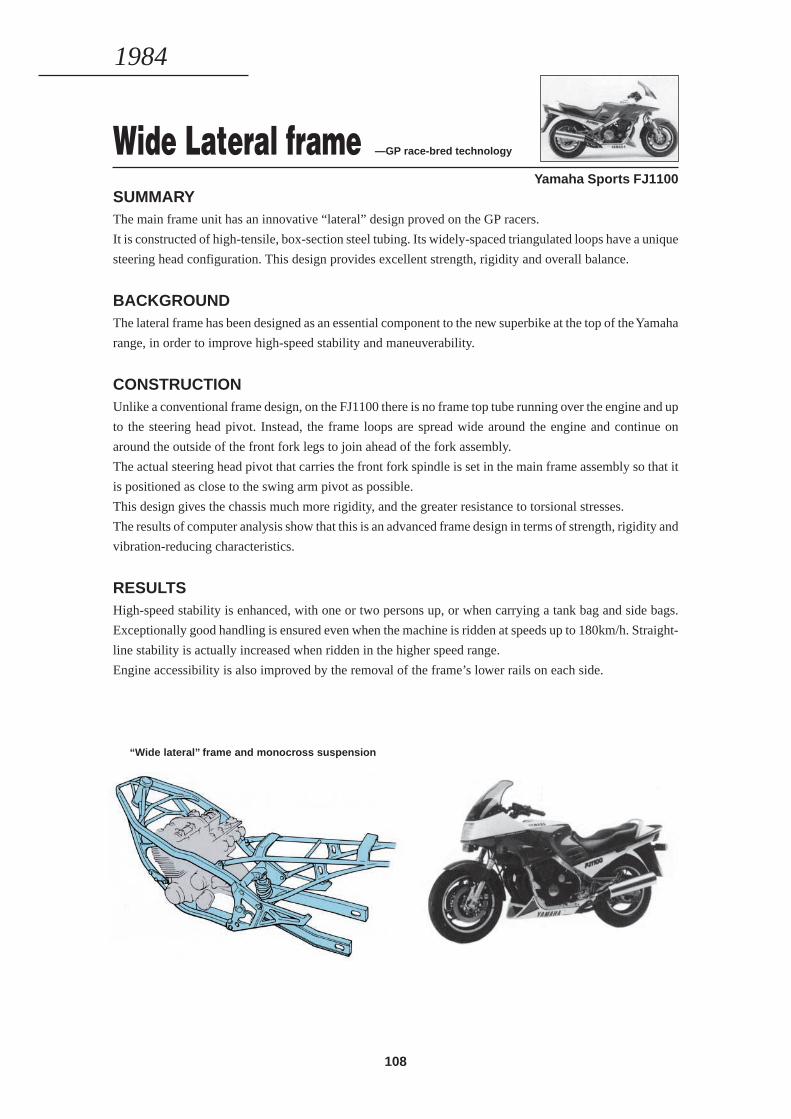
108
Wide Lateral frame —GP race-bred technology
Yamaha Sports FJ1100SUMMARYThe main frame unit has an innovative “lateral” design proved on the GP racers.
It is constructed of high-tensile, box-section steel tubing. Its widely-spaced triangulated loops have a unique
steering head configuration. This design provides excellent strength, rigidity and overall balance.
BACKGROUNDThe lateral frame has been designed as an essential component to the new superbike at the top of the Yamaha
range, in order to improve high-speed stability and maneuverability.
CONSTRUCTIONUnlike a conventional frame design, on the FJ1100 there is no frame top tube running over the engine and up
to the steering head pivot. Instead, the frame loops are spread wide around the engine and continue on
around the outside of the front fork legs to join ahead of the fork assembly.
The actual steering head pivot that carries the front fork spindle is set in the main frame assembly so that it
is positioned as close to the swing arm pivot as possible.
This design gives the chassis much more rigidity, and the greater resistance to torsional stresses.
The results of computer analysis show that this is an advanced frame design in terms of strength, rigidity and
vibration-reducing characteristics.
RESULTSHigh-speed stability is enhanced, with one or two persons up, or when carrying a tank bag and side bags.
Exceptionally good handling is ensured even when the machine is ridden at speeds up to 180km/h. Straight-
line stability is actually increased when ridden in the higher speed range.
Engine accessibility is also improved by the removal of the frame’s lower rails on each side.
1984
“Wide lateral” frame and monocross suspension
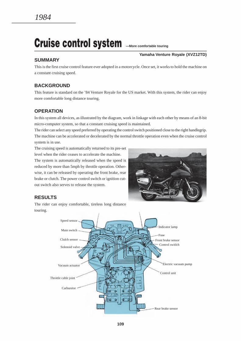
109
Cruise control system —More comfortable touring
Yamaha Venture Royale (XVZ12TD)SUMMARYThis is the first cruise control feature ever adopted in a motorcycle. Once set, it works to hold the machine on
a constant cruising speed.
BACKGROUNDThis feature is standard on the ’84 Venture Royale for the US market. With this system, the rider can enjoy
more comfortable long distance touring.
OPERATIONIn this system all devices, as illustrated by the diagram, work in linkage with each other by means of an 8-bit
micro-computer system, so that a constant cruising speed is maintained.
The rider can select any speed preferred by operating the control switch positioned close to the right handlegrip.
The machine can be accelerated or decelerated by the normal throttle operation even when the cruise control
system is in use.
The cruising speed is automatically returned to its pre-set
level when the rider ceases to accelerate the machine.
The system is automatically released when the speed is
reduced by more than 5mph by throttle operation. Other-
wise, it can be released by operating the front brake, rear
brake or clutch. The power control switch or ignition cut-
out switch also serves to release the system.
RESULTSThe rider can enjoy comfortable, tireless long distance
touring.
1984
Speed sensor
Main switch
Clulch sensor
Solenoid valve
Vacuum actuator
Throttle cable joint
Carburetor
Indicator lamp
Fuse
Front brake sensorControl switlch
Electric vacuum pump
Control unit
Rear brake sensor

110
2-stroke V-4 engine —Another race-bred
technology Yamaha Sports RZV500R (RD500LC)SUMMARYThis engine has been developed for the new Yamaha Sports RZV500R (RD500LC), following the layout of
the GP-winning YZR500. It adopts a liquid-cooled 2-stroke V-4 design with the YPVS linked Autolube
system.
BACKGROUDAt a time when racer technology is getting more attention as an important base for the development of high
performance supersports bikes, the ’84 RZV500R (RD500LC) has made its debut as the ultimate 2-stroke
road machine that features all of Yamaha’s long accumulated 2-stroke technology.
The RZV500R (RD500LC) is part of a powerful RZ trio including the RZ250RR and RZ350RR.
CONSTRUCTIONIt is designed as a true replica of the YZR500 with which Kenny Roberts won six Grand Prix rounds in the
1983 World Championship series.
On this model, however, a piston reed valve intake system has been adopted for the front cylinders and a
crankcase reed valve intake system for the rear cylinders, while the YZR500 features a rotary disc valve
intake system. This provides the best possible match to the power development characteristics of this high
performance supersports model.
The two banks of cylinders are set at the narrowest feasible angle (50 degrees) and in this V bank four cable-
controlled carburetors are neatly arranged to make the unit as
compact as possible.
Another important part of this engine’s performance poten-
tial comes from the Yamaha Power Valve System (YPVS) used
in the exhaust system.
This system, along with the proven function of the electronic
governor type CDI system, helps to ensure smooth power
development characteristics over the entire speed range.
The newly designed 6-speed transmission is pressure-lubricated.
1984
RZV500R 2-stroke V-4 engine

111
COMPUTERIZED STRUCTURE ANALYSISThe strength and rigidity of chassis and individual component parts are analyzed by means of a computer.
This computerized method applies also to vibration analysis and stress analysis against external force, help-
ing to improve product quality.
COLOR HIGHLIGHT
COLOR HIGHLIGHT
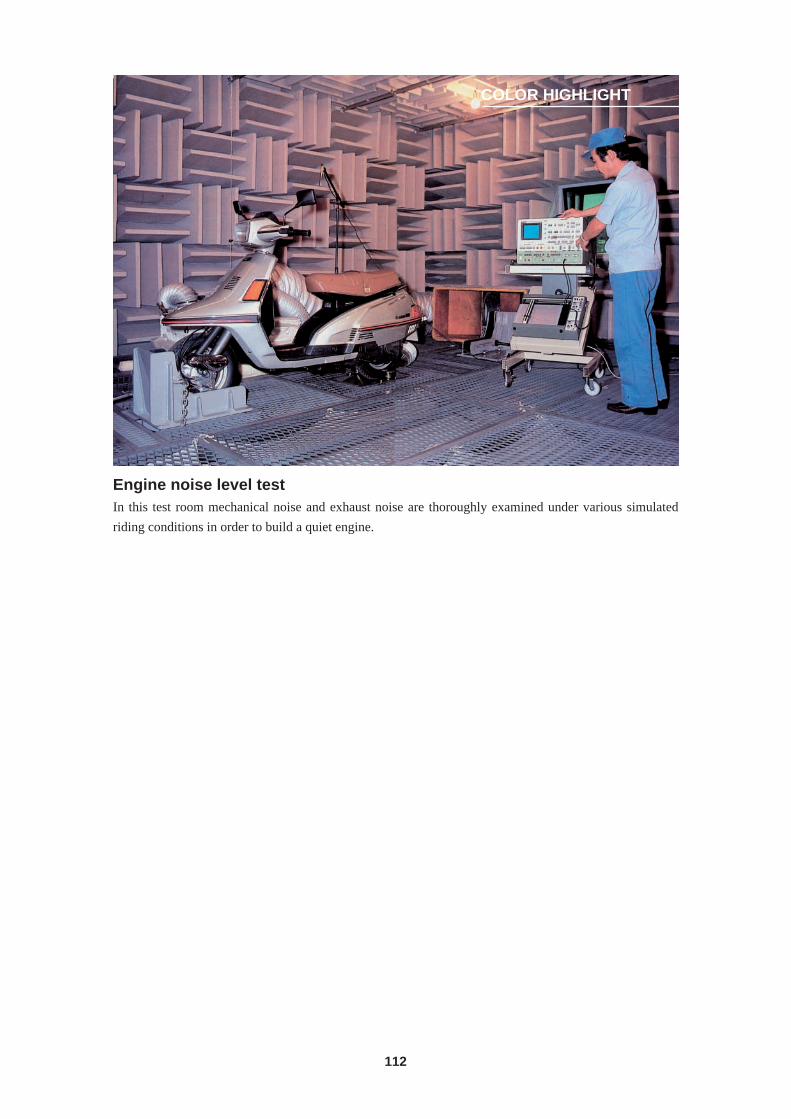
112
Engine noise level testIn this test room mechanical noise and exhaust noise are thoroughly examined under various simulated
riding conditions in order to build a quiet engine.
COLOR HIGHLIGHT
113
YAMAHA MOTORCYCLETECHNICAL GUIDE
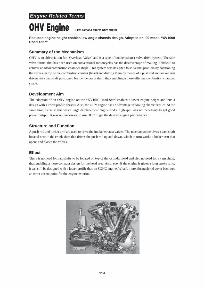
114
Reduced engine height enables low-angle chassis design. Adopted on ’99 model “XV1600Road Star.”
OHV Engine —First Yamaha sports OHV engine
Summary of the MechanismOHV is an abbreviation for “Overhead Valve” and is a type of intake/exhaust valve drive system. The side
valve format that has been used on conventional motorcycles has the disadvantage of making it difficult to
achieve an ideal combustion chamber shape. This system was designed to solve that problem by positioning
the valves on top of the combustion camber (head) and driving them by means of a push rod and locker arm
driven via a camshaft positioned beside the crank shaft, thus enabling a more efficient combustion chamber
shape.
Development AimThe adoption of an OHV engine on the “XV1600 Road Star” enables a lower engine height and thus a
design with a lower profile chassis. Also, the OHV engine has an advantage in cooling characteristics. At the
same time, because this was a large displacement engine and a high rpm was not necessary to get good
power out-put, it was not necessary to use OHC to get the desired engine performance.
Structure and FunctionA push rod and locker arm are used to drive the intake/exhaust valves. The mechanism involves a cam shaft
located next to the crank shaft that drives the push rod up and down, which in turn works a locker arm that
opens and closes the valves.
EffectThere is no need for camshafts to be located on top of the cylinder head and also no need for a cam chain,
thus enabling a more compact design for the head area. Also, even if the engine is given a long stroke ratio,
it can still be designed with a lower profile than an SOHC engine. What’s more, the push rod cover becomes
an extra accent point for the engine exterior.
Engine Related Terms
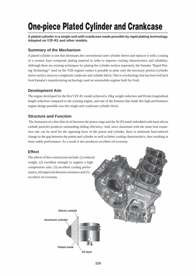
115
A plated cylinder in a single-unit with crankcase made possible by rapid plating technology.Adopted on YZF-R1 and other models.
One-piece Plated Cylinder and Crankcase
Summary of the MechanismA plated cylinder is one that eliminates the conventional steel cylinder sleeve and replaces it with a coating
of a ceramic base cornposite plating material in order to improve cooling characteristics and reliability.
Although there are existing techniques for plating the cylinder surface separately, the Yamaha “Rapid Plat-
ing Technology” used on the TZR engines makes it possible to plate only the necessary portion (cylinder
sleeve surface area) on a singleunit crankcase and cylinder block. This is a technology that has been fed back
fromYamaha’s manufacturing technology used on automobile engines built for Ford.
Development AimThe engine developed for the first YZF-R1 model achieved a 10kg weight reduction and 81mm longitudinal
length reduction compared to the existing engine, and one of the features that made this high-performance
engine design possible was this single-unit crankcase-cylinder block.
Structure and Function The formation of a thin film of oil between the piston rings and the Ni (P) metal imbedded with hard silicon
carbide particles produces outstanding sliding efficiency. And, since aluminum with the same heat expan-
sion rate can be used for the opposing faces of the piston and cylinder, there is minimum heat-induced
change in the gap between the piston and cylinder as well as better cooling characteristics, thus resulting in
more stable performance. As a result it also produces excellent oil economy.
EffectThe effects of this construction include: (1) reduced
weight, (2) excellent strength to support a high
compression ratio. (3) excellent cooling perfor-
mance, (4) improved abrasion resistance and (5)
excellent oil economy.
Silicon carbide
Aluminum cylinder
Plated metal
Oil layer
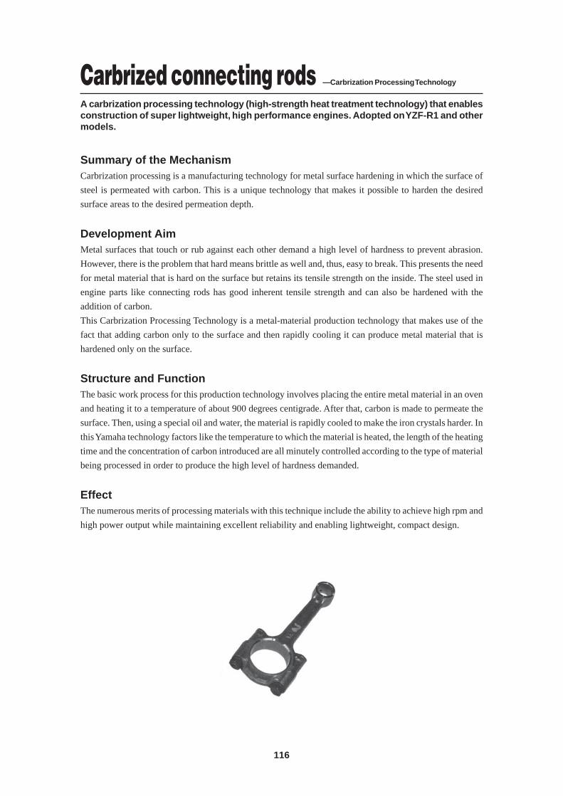
116
Carbrized connecting rods —Carbrization Processing Technology
A carbrization processing technology (high-strength heat treatment technology) that enablesconstruction of super lightweight, high performance engines. Adopted on YZF-R1 and othermodels.
Summary of the MechanismCarbrization processing is a manufacturing technology for metal surface hardening in which the surface of
steel is permeated with carbon. This is a unique technology that makes it possible to harden the desired
surface areas to the desired permeation depth.
Development AimMetal surfaces that touch or rub against each other demand a high level of hardness to prevent abrasion.
However, there is the problem that hard means brittle as well and, thus, easy to break. This presents the need
for metal material that is hard on the surface but retains its tensile strength on the inside. The steel used in
engine parts like connecting rods has good inherent tensile strength and can also be hardened with the
addition of carbon.
This Carbrization Processing Technology is a metal-material production technology that makes use of the
fact that adding carbon only to the surface and then rapidly cooling it can produce metal material that is
hardened only on the surface.
Structure and FunctionThe basic work process for this production technology involves placing the entire metal material in an oven
and heating it to a temperature of about 900 degrees centigrade. After that, carbon is made to permeate the
surface. Then, using a special oil and water, the material is rapidly cooled to make the iron crystals harder. In
this Yamaha technology factors like the temperature to which the material is heated, the length of the heating
time and the concentration of carbon introduced are all minutely controlled according to the type of material
being processed in order to produce the high level of hardness demanded.
EffectThe numerous merits of processing materials with this technique include the ability to achieve high rpm and
high power output while maintaining excellent reliability and enabling lightweight, compact design.
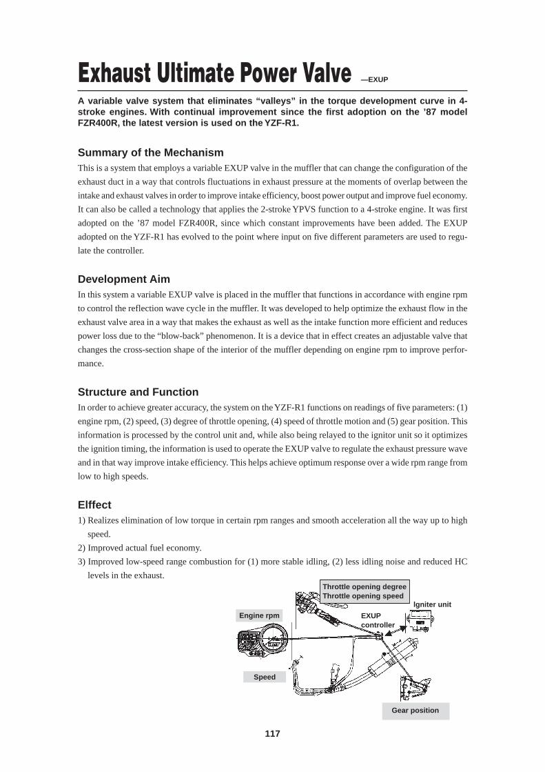
117
Engine rpm
Speed
Throttle opening degreeThrottle opening speed
EXUPcontroller
lgniter unit
Gear position
Exhaust Ultimate Power Valve —EXUP
A variable valve system that eliminates “valleys” in the torque development curve in 4-stroke engines. With continual improvement since the first adoption on the ’87 modelFZR400R, the latest version is used on the YZF-R1.
Summary of the MechanismThis is a system that employs a variable EXUP valve in the muffler that can change the configuration of the
exhaust duct in a way that controls fluctuations in exhaust pressure at the moments of overlap between the
intake and exhaust valves in order to improve intake efficiency, boost power output and improve fuel economy.
It can also be called a technology that applies the 2-stroke YPVS function to a 4-stroke engine. It was first
adopted on the ’87 model FZR400R, since which constant improvements have been added. The EXUP
adopted on the YZF-R1 has evolved to the point where input on five different parameters are used to regu-
late the controller.
Development AimIn this system a variable EXUP valve is placed in the muffler that functions in accordance with engine rpm
to control the reflection wave cycle in the muffler. It was developed to help optimize the exhaust flow in the
exhaust valve area in a way that makes the exhaust as well as the intake function more efficient and reduces
power loss due to the “blow-back” phenomenon. It is a device that in effect creates an adjustable valve that
changes the cross-section shape of the interior of the muffler depending on engine rpm to improve perfor-
mance.
Structure and FunctionIn order to achieve greater accuracy, the system on the YZF-R1 functions on readings of five parameters: (1)
engine rpm, (2) speed, (3) degree of throttle opening, (4) speed of throttle motion and (5) gear position. This
information is processed by the control unit and, while also being relayed to the ignitor unit so it optimizes
the ignition timing, the information is used to operate the EXUP valve to regulate the exhaust pressure wave
and in that way improve intake efficiency. This helps achieve optimum response over a wide rpm range from
low to high speeds.
Elffect1) Realizes elimination of low torque in certain rpm ranges and smooth acceleration all the way up to high
speed.
2) Improved actual fuel economy.
3) Improved low-speed range combustion for (1) more stable idling, (2) less idling noise and reduced HC
levels in the exhaust.
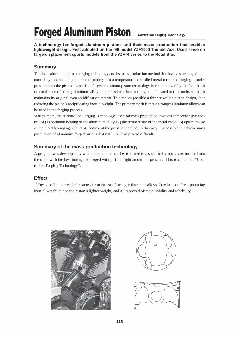
118
Forged Aluminum Piston —Controlled Forging Technology
A technology for forged aluminum pistons and their mass production that enableslightweight design. First adopted on the ’96 model YZF1000 ThunderAce. Used since onlarge-displacement sports models from the YZF-R series to the Road Star.
SummaryThis is an aluminum piston forging technology and its mass production method that involves heating alumi-
num alloy to a set temperature and putting it in a temperature-controlled metal mold and forging it under
pressure into the piston shape. This forged aluminum piston technology is characterized by the fact that it
can make use of strong aluminum alloy material which does not have to be heated until it melts so that it
maintains its original even solidification matrix. This makes possible a thinner-walled piston design, thus
reducing the piston’s reciprocating inertial weight. The primary merit is that a stronger aluminum alloys can
be used in the forging process.
What’s more, the “Controlled Forging Technology” used for mass production involves comprehensive con-
trol of (1) optimum heating of the aluminum alloy, (2) the temperature of the metal mold, (3) optimum use
of the mold freeing agent and (4) control of the pressure applied. In this way it is possible to achieve mass
production of aluminum forged pistons that until now had proved difficult.
Summary of the mass production technologyA program was developed by which the aluminum alloy is heated to a specified temperature, inserted into
the mold with the best timing and forged with just the right amount of pressure. This is called our “Con-
trolled Forging Technology”.
Effect1) Design of thinner-walled pistons due to the use of stronger aluminum alloys, 2) reduction of reci-procating
inertial weight due to the piston’s lighter weight, and 3) improved piston durability and reliability.
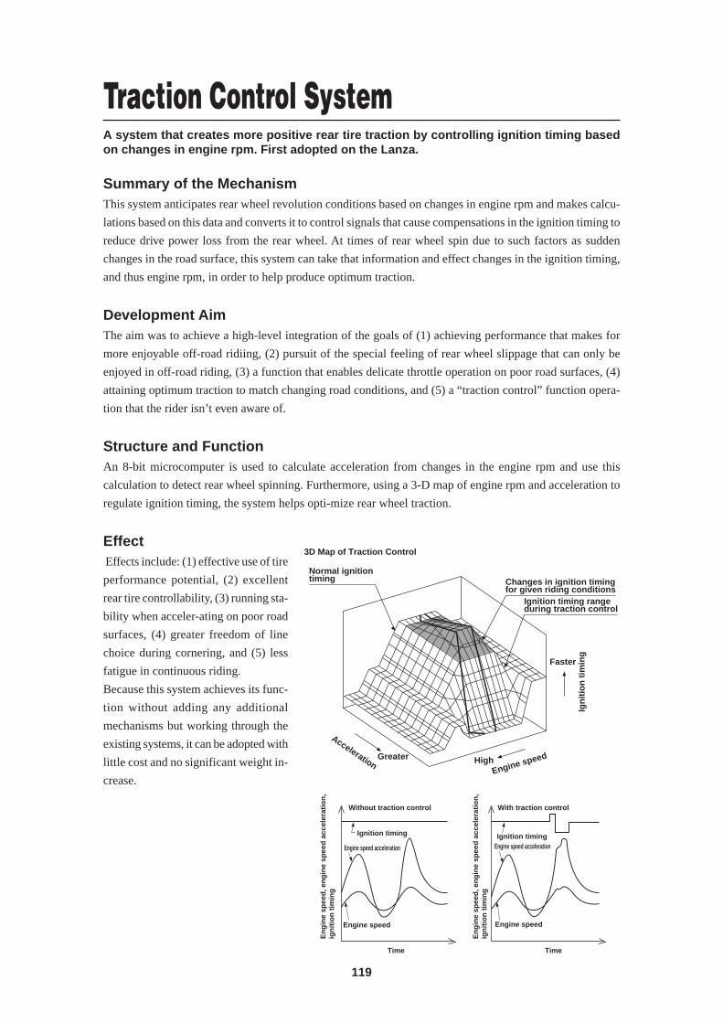
119
3D Map of Traction Control
Normal ignition timing
Greater
Acceleration
Changes in ignition timing for given riding conditions
Ignition timing range during traction control
Ign
itio
n t
imin
g
Faster
Engine speedHigh
Traction Control SystemA system that creates more positive rear tire traction by controlling ignition timing basedon changes in engine rpm. First adopted on the Lanza.
Summary of the MechanismThis system anticipates rear wheel revolution conditions based on changes in engine rpm and makes calcu-
lations based on this data and converts it to control signals that cause compensations in the ignition timing to
reduce drive power loss from the rear wheel. At times of rear wheel spin due to such factors as sudden
changes in the road surface, this system can take that information and effect changes in the ignition timing,
and thus engine rpm, in order to help produce optimum traction.
Development AimThe aim was to achieve a high-level integration of the goals of (1) achieving performance that makes for
more enjoyable off-road ridiing, (2) pursuit of the special feeling of rear wheel slippage that can only be
enjoyed in off-road riding, (3) a function that enables delicate throttle operation on poor road surfaces, (4)
attaining optimum traction to match changing road conditions, and (5) a “traction control” function opera-
tion that the rider isn’t even aware of.
Structure and FunctionAn 8-bit microcomputer is used to calculate acceleration from changes in the engine rpm and use this
calculation to detect rear wheel spinning. Furthermore, using a 3-D map of engine rpm and acceleration to
regulate ignition timing, the system helps opti-mize rear wheel traction.
Effect Effects include: (1) effective use of tire
performance potential, (2) excellent
rear tire controllability, (3) running sta-
bility when acceler-ating on poor road
surfaces, (4) greater freedom of line
choice during cornering, and (5) less
fatigue in continuous riding.
Because this system achieves its func-
tion without adding any additional
mechanisms but working through the
existing systems, it can be adopted with
little cost and no significant weight in-
crease.
Without traction control With traction control
Ignition timing Ignition timing
Engine speed acceleration Engine speed acceleration
Engine speed Engine speed
Time Time
En
gin
e sp
eed
, en
gin
e sp
eed
acc
eler
atio
n,
ign
itio
n t
imin
g
En
gin
e sp
eed
, en
gin
e sp
eed
acc
eler
atio
n,
ign
itio
n t
imin
g
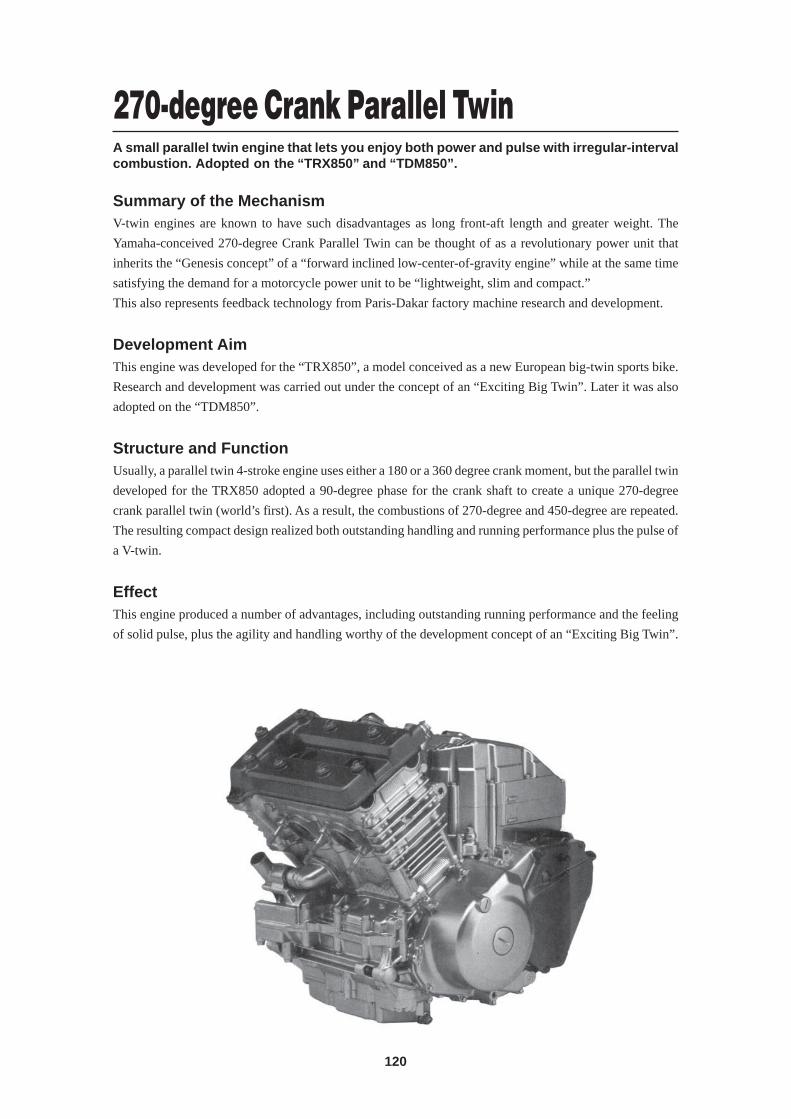
120
270-degree Crank Parallel TwinA small parallel twin engine that lets you enjoy both power and pulse with irregular-intervalcombustion. Adopted on the “TRX850” and “TDM850”.
Summary of the MechanismV-twin engines are known to have such disadvantages as long front-aft length and greater weight. The
Yamaha-conceived 270-degree Crank Parallel Twin can be thought of as a revolutionary power unit that
inherits the “Genesis concept” of a “forward inclined low-center-of-gravity engine” while at the same time
satisfying the demand for a motorcycle power unit to be “lightweight, slim and compact.”
This also represents feedback technology from Paris-Dakar factory machine research and development.
Development AimThis engine was developed for the “TRX850”, a model conceived as a new European big-twin sports bike.
Research and development was carried out under the concept of an “Exciting Big Twin”. Later it was also
adopted on the “TDM850”.
Structure and FunctionUsually, a parallel twin 4-stroke engine uses either a 180 or a 360 degree crank moment, but the parallel twin
developed for the TRX850 adopted a 90-degree phase for the crank shaft to create a unique 270-degree
crank parallel twin (world’s first). As a result, the combustions of 270-degree and 450-degree are repeated.
The resulting compact design realized both outstanding handling and running performance plus the pulse of
a V-twin.
EffectThis engine produced a number of advantages, including outstanding running performance and the feeling
of solid pulse, plus the agility and handling worthy of the development concept of an “Exciting Big Twin”.
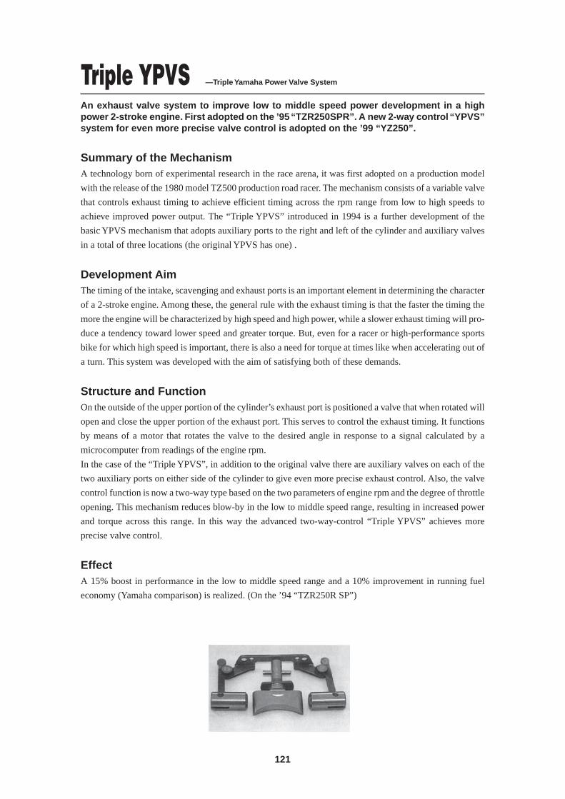
121
Triple YPVS —Triple Yamaha Power Valve System
An exhaust valve system to improve low to middle speed power development in a highpower 2-stroke engine. First adopted on the ’95 “TZR250SPR”. A new 2-way control “YPVS”system for even more precise valve control is adopted on the ’99 “YZ250”.
Summary of the MechanismA technology born of experimental research in the race arena, it was first adopted on a production model
with the release of the 1980 model TZ500 production road racer. The mechanism consists of a variable valve
that controls exhaust timing to achieve efficient timing across the rpm range from low to high speeds to
achieve improved power output. The “Triple YPVS” introduced in 1994 is a further development of the
basic YPVS mechanism that adopts auxiliary ports to the right and left of the cylinder and auxiliary valves
in a total of three locations (the original YPVS has one) .
Development AimThe timing of the intake, scavenging and exhaust ports is an important element in determining the character
of a 2-stroke engine. Among these, the general rule with the exhaust timing is that the faster the timing the
more the engine will be characterized by high speed and high power, while a slower exhaust timing will pro-
duce a tendency toward lower speed and greater torque. But, even for a racer or high-performance sports
bike for which high speed is important, there is also a need for torque at times like when accelerating out of
a turn. This system was developed with the aim of satisfying both of these demands.
Structure and FunctionOn the outside of the upper portion of the cylinder’s exhaust port is positioned a valve that when rotated will
open and close the upper portion of the exhaust port. This serves to control the exhaust timing. It functions
by means of a motor that rotates the valve to the desired angle in response to a signal calculated by a
microcomputer from readings of the engine rpm.
In the case of the “Triple YPVS”, in addition to the original valve there are auxiliary valves on each of the
two auxiliary ports on either side of the cylinder to give even more precise exhaust control. Also, the valve
control function is now a two-way type based on the two parameters of engine rpm and the degree of throttle
opening. This mechanism reduces blow-by in the low to middle speed range, resulting in increased power
and torque across this range. In this way the advanced two-way-control “Triple YPVS” achieves more
precise valve control.
EffectA 15% boost in performance in the low to middle speed range and a 10% improvement in running fuel
economy (Yamaha comparison) is realized. (On the ’94 “TZR250R SP”)
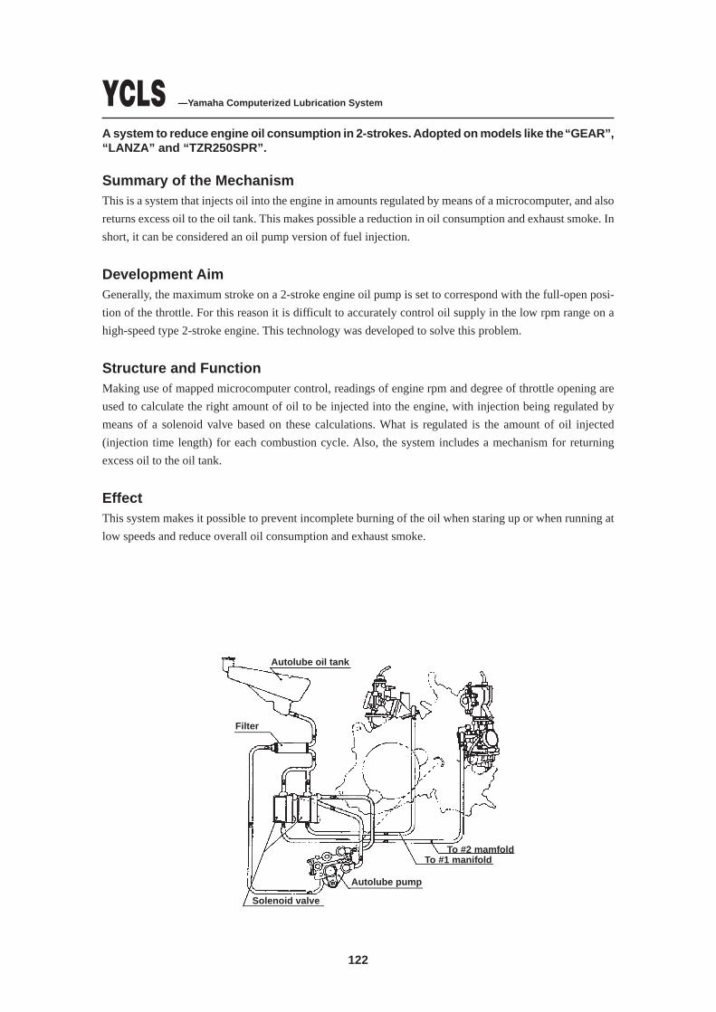
122
YCLS —Yamaha Computerized Lubrication System
A system to reduce engine oil consumption in 2-strokes. Adopted on models like the “GEAR”,“LANZA” and “TZR250SPR”.
Summary of the MechanismThis is a system that injects oil into the engine in amounts regulated by means of a microcomputer, and also
returns excess oil to the oil tank. This makes possible a reduction in oil consumption and exhaust smoke. In
short, it can be considered an oil pump version of fuel injection.
Development AimGenerally, the maximum stroke on a 2-stroke engine oil pump is set to correspond with the full-open posi-
tion of the throttle. For this reason it is difficult to accurately control oil supply in the low rpm range on a
high-speed type 2-stroke engine. This technology was developed to solve this problem.
Structure and FunctionMaking use of mapped microcomputer control, readings of engine rpm and degree of throttle opening are
used to calculate the right amount of oil to be injected into the engine, with injection being regulated by
means of a solenoid valve based on these calculations. What is regulated is the amount of oil injected
(injection time length) for each combustion cycle. Also, the system includes a mechanism for returning
excess oil to the oil tank.
EffectThis system makes it possible to prevent incomplete burning of the oil when staring up or when running at
low speeds and reduce overall oil consumption and exhaust smoke.
Autolube oil tank
Filter
Solenoid valve
Autolube pump
To #1 manifoldTo #2 mamfold
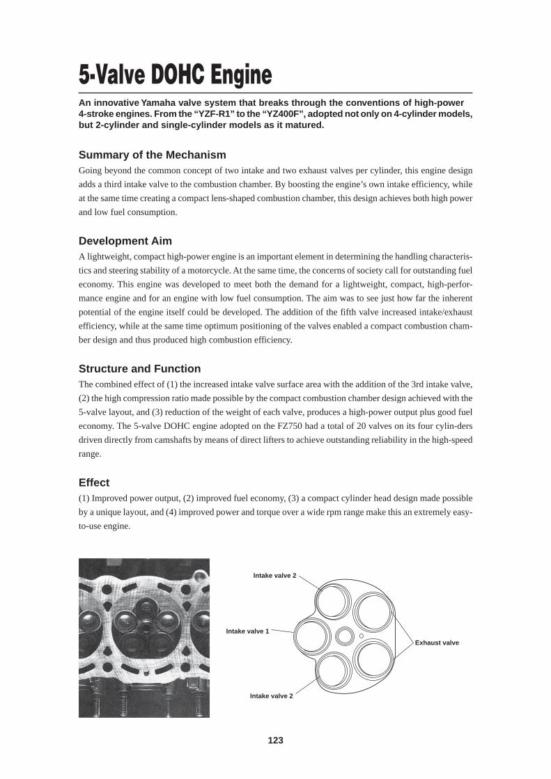
123
5-Valve DOHC EngineAn innovative Yamaha valve system that breaks through the conventions of high-power4-stroke engines. From the “YZF-R1” to the “YZ400F”, adopted not only on 4-cylinder models,but 2-cylinder and single-cylinder models as it matured.
Summary of the MechanismGoing beyond the common concept of two intake and two exhaust valves per cylinder, this engine design
adds a third intake valve to the combustion chamber. By boosting the engine’s own intake efficiency, while
at the same time creating a compact lens-shaped combustion chamber, this design achieves both high power
and low fuel consumption.
Development AimA lightweight, compact high-power engine is an important element in determining the handling characteris-
tics and steering stability of a motorcycle. At the same time, the concerns of society call for outstanding fuel
economy. This engine was developed to meet both the demand for a lightweight, compact, high-perfor-
mance engine and for an engine with low fuel consumption. The aim was to see just how far the inherent
potential of the engine itself could be developed. The addition of the fifth valve increased intake/exhaust
efficiency, while at the same time optimum positioning of the valves enabled a compact combustion cham-
ber design and thus produced high combustion efficiency.
Structure and FunctionThe combined effect of (1) the increased intake valve surface area with the addition of the 3rd intake valve,
(2) the high compression ratio made possible by the compact combustion chamber design achieved with the
5-valve layout, and (3) reduction of the weight of each valve, produces a high-power output plus good fuel
economy. The 5-valve DOHC engine adopted on the FZ750 had a total of 20 valves on its four cylin-ders
driven directly from camshafts by means of direct lifters to achieve outstanding reliability in the high-speed
range.
Effect(1) Improved power output, (2) improved fuel economy, (3) a compact cylinder head design made possible
by a unique layout, and (4) improved power and torque over a wide rpm range make this an extremely easy-
to-use engine.
Intake valve 2
Intake valve 2
Intake valve 1
Exhaust valve
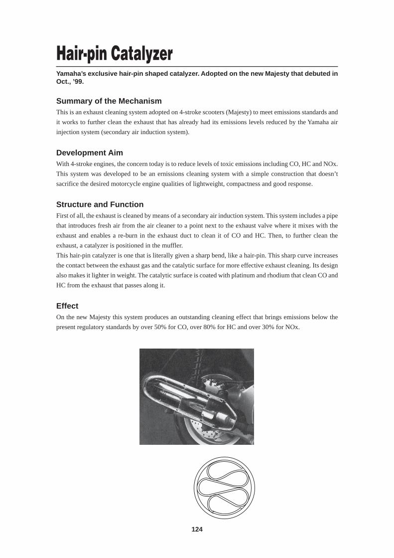
124
Hair-pin CatalyzerYamaha’s exclusive hair-pin shaped catalyzer. Adopted on the new Majesty that debuted inOct., ’99.
Summary of the MechanismThis is an exhaust cleaning system adopted on 4-stroke scooters (Majesty) to meet emissions standards and
it works to further clean the exhaust that has already had its emissions levels reduced by the Yamaha air
injection system (secondary air induction system).
Development AimWith 4-stroke engines, the concern today is to reduce levels of toxic emissions including CO, HC and NOx.
This system was developed to be an ernissions cleaning system with a simple construction that doesn’t
sacrifice the desired motorcycle engine qualities of lightweight, compactness and good response.
Structure and FunctionFirst of all, the exhaust is cleaned by means of a secondary air induction system. This system includes a pipe
that introduces fresh air from the air cleaner to a point next to the exhaust valve where it mixes with the
exhaust and enables a re-burn in the exhaust duct to clean it of CO and HC. Then, to further clean the
exhaust, a catalyzer is positioned in the muffler.
This hair-pin catalyzer is one that is literally given a sharp bend, like a hair-pin. This sharp curve increases
the contact between the exhaust gas and the catalytic surface for more effective exhaust cleaning. Its design
also makes it lighter in weight. The catalytic surface is coated with platinum and rhodium that clean CO and
HC from the exhaust that passes along it.
EffectOn the new Majesty this system produces an outstanding cleaning effect that brings emissions below the
present regulatory standards by over 50% for CO, over 80% for HC and over 30% for NOx.
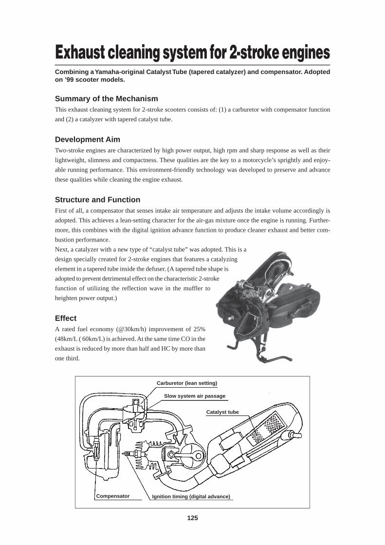
125
Exhaust cleaning system for 2-stroke enginesCombining a Yamaha-original Catalyst Tube (tapered catalyzer) and compensator. Adoptedon ’99 scooter models.
Summary of the MechanismThis exhaust cleaning system for 2-stroke scooters consists of: (1) a carburetor with compensator function
and (2) a catalyzer with tapered catalyst tube.
Development AimTwo-stroke engines are characterized by high power output, high rpm and sharp response as well as their
lightweight, slimness and compactness. These qualities are the key to a motorcycle’s sprightly and enjoy-
able running performance. This environment-friendly technology was developed to preserve and advance
these qualities while cleaning the engine exhaust.
Structure and FunctionFirst of all, a compensator that senses intake air temperature and adjusts the intake volume accordingly is
adopted. This achieves a lean-setting character for the air-gas mixture once the engine is running. Further-
more, this combines with the digital ignition advance function to produce cleaner exhaust and better com-
bustion performance.
Next, a catalyzer with a new type of “catalyst tube” was adopted. This is a
design specially created for 2-stroke engines that features a catalyzing
element in a tapered tube inside the defuser. (A tapered tube shape is
adopted to prevent detrimental effect on the characteristic 2-stroke
function of utilizing the reflection wave in the muffler to
heighten power output.)
EffectA rated fuel economy (@30km/h) improvement of 25%
(48km/L ( 60km/L) is achieved. At the same time CO in the
exhaust is reduced by more than half and HC by more than
one third.
Carburetor (lean setting)
Catalyst tube
Compensator Ignition timing (digital advance)
Slow system air passage
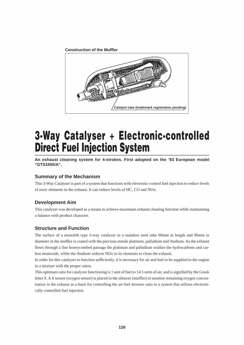
126
3-Way Catalyser + Electronic-controlledDirect Fuel Injection SystemAn exhaust cleaning system for 4-strokes. First adopted on the ’93 European model“GTS1000/A”.
Summary of the MechanismThis 3-Way Catalyser is part of a system that functions with electronic-control fuel injection to reduce levels
of toxic elements in the exhaust. It can reduce levels of HC, CO and NOx.
Development AimThis catalyzer was developed as a means to achieve maximum exhaust cleaning function while maintaining
a balance with product character.
Structure and FunctionThe surface of a monolith type 3-way catalyzer in a stainless steel tube 60mm in length and 90mm in
diameter in the muffler is coated with the precious metals platinum, palladium and rhodium. As the exhaust
flows through a fine honeycombed passage the platinum and palladium oxidize the hydrocarbons and car-
bon monoxide, while the rhodium reduces NOx to its elements to clean the exhaust.
In order for this catalyzer to function sufficiently, it is necessary for air and fuel to be supplied to the engine
in a mixture with the proper ratios.
This optimum ratio for catalyzer functioning is 1 unit of fuel to 14.5 units of air, and is signified by the Greek
letter λ. A λ sensor (oxygen sensor) is placed in the silencer (muffler) to monitor remaining oxygen concen-
tration in the exhaust as a basis for controlling the air-fuel mixture ratio in a system that utilizes electroni-
cally controlled fuel injection.
Construction of the Muffler
Catalyst tube (trademark registration pending)
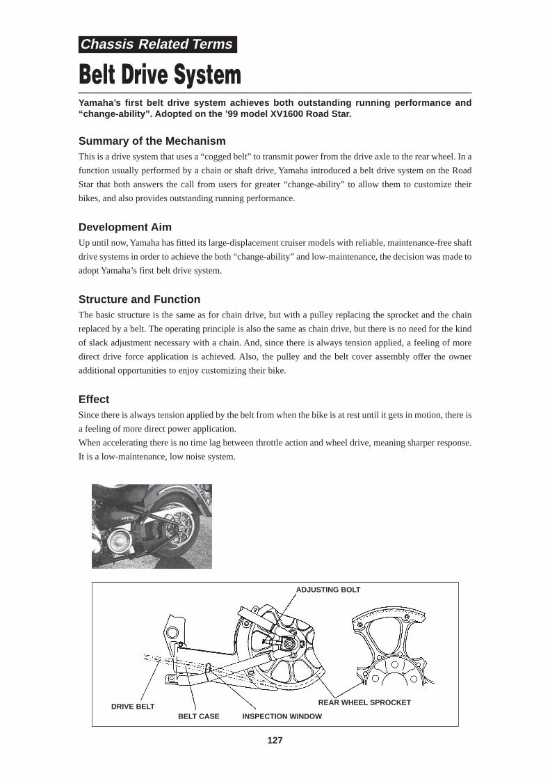
127
Belt Drive SystemYamaha’s first belt drive system achieves both outstanding running performance and“change-ability”. Adopted on the ’99 model XV1600 Road Star.
Summary of the MechanismThis is a drive system that uses a “cogged belt” to transmit power from the drive axle to the rear wheel. In a
function usually performed by a chain or shaft drive, Yamaha introduced a belt drive system on the Road
Star that both answers the call from users for greater “change-ability” to allow them to customize their
bikes, and also provides outstanding running performance.
Development AimUp until now, Yamaha has fitted its large-displacement cruiser models with reliable, maintenance-free shaft
drive systems in order to achieve the both “change-ability” and low-maintenance, the decision was made to
adopt Yamaha’s first belt drive system.
Structure and FunctionThe basic structure is the same as for chain drive, but with a pulley replacing the sprocket and the chain
replaced by a belt. The operating principle is also the same as chain drive, but there is no need for the kind
of slack adjustment necessary with a chain. And, since there is always tension applied, a feeling of more
direct drive force application is achieved. Also, the pulley and the belt cover assembly offer the owner
additional opportunities to enjoy customizing their bike.
EffectSince there is always tension applied by the belt from when the bike is at rest until it gets in motion, there is
a feeling of more direct power application.
When accelerating there is no time lag between throttle action and wheel drive, meaning sharper response.
It is a low-maintenance, low noise system.
ADJUSTING BOLT
DRIVE BELTBELT CASE INSPECTION WINDOW
REAR WHEEL SPROCKET
Chassis Related Terms
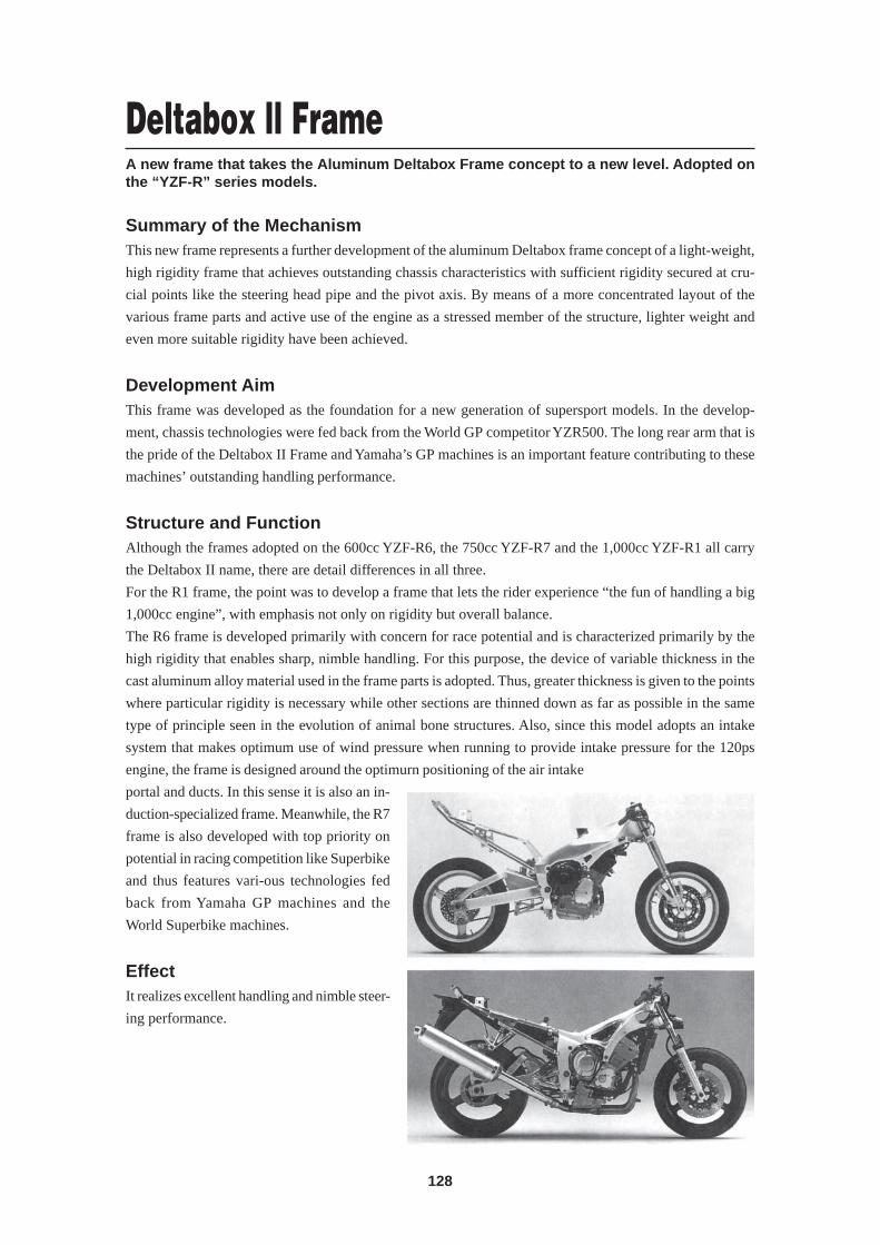
128
Deltabox ll FrameA new frame that takes the Aluminum Deltabox Frame concept to a new level. Adopted onthe “YZF-R” series models.
Summary of the MechanismThis new frame represents a further development of the aluminum Deltabox frame concept of a light-weight,
high rigidity frame that achieves outstanding chassis characteristics with sufficient rigidity secured at cru-
cial points like the steering head pipe and the pivot axis. By means of a more concentrated layout of the
various frame parts and active use of the engine as a stressed member of the structure, lighter weight and
even more suitable rigidity have been achieved.
Development AimThis frame was developed as the foundation for a new generation of supersport models. In the develop-
ment, chassis technologies were fed back from the World GP competitor YZR500. The long rear arm that is
the pride of the Deltabox II Frame and Yamaha’s GP machines is an important feature contributing to these
machines’ outstanding handling performance.
Structure and FunctionAlthough the frames adopted on the 600cc YZF-R6, the 750cc YZF-R7 and the 1,000cc YZF-R1 all carry
the Deltabox II name, there are detail differences in all three.
For the R1 frame, the point was to develop a frame that lets the rider experience “the fun of handling a big
1,000cc engine”, with emphasis not only on rigidity but overall balance.
The R6 frame is developed primarily with concern for race potential and is characterized primarily by the
high rigidity that enables sharp, nimble handling. For this purpose, the device of variable thickness in the
cast aluminum alloy material used in the frame parts is adopted. Thus, greater thickness is given to the points
where particular rigidity is necessary while other sections are thinned down as far as possible in the same
type of principle seen in the evolution of animal bone structures. Also, since this model adopts an intake
system that makes optimum use of wind pressure when running to provide intake pressure for the 120ps
engine, the frame is designed around the optimurn positioning of the air intake
portal and ducts. In this sense it is also an in-
duction-specialized frame. Meanwhile, the R7
frame is also developed with top priority on
potential in racing competition like Superbike
and thus features vari-ous technologies fed
back from Yamaha GP machines and the
World Superbike machines.
EffectIt realizes excellent handling and nimble steer-
ing performance.
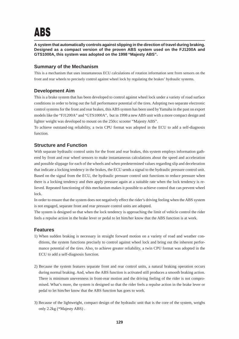
129
A system that automatically controls against slipping in the direction of travel during braking.Designed as a compact version of the proven ABS system used on the FJ1200A andGTS1000A, this system was adopted on the 1998 “Majesty ABS”.
Summary of the MechanismThis is a mechanism that uses instantaneous ECU calculations of rotation information sent frorn sensors on the
front and rear wheels to precisely control against wheel lock by regulating the brakes’ hydraulic systems.
Development AimThis is a brake system that has been developed to control against wheel lock under a variety of road surface
conditions in order to bring out the full performance potential of the tires. Adopting two separate electronic
control systems for the front and rear brakes, this ABS system has been used by Yamaha in the past on export
models like the “FJ1200A” and “GTS1000A”, but in 1998 a new ABS unit with a more compact design and
lighter weight was developed to mount on the 250cc scooter “Majesty ABS”.
To achieve outstand-ing reliability, a twin CPU format was adopted in the ECU to add a self-diagnosis
function.
Structure and FunctionWith separate hydraulic control units for the front and rear brakes, this system employs information gath-
ered by front and rear wheel sensors to make instantaneous calculations about the speed and acceleration
and possible slippage for each of the wheels and when predetermined values regarding slip and deceleration
that indicate a locking tendency in the brakes, the ECU sends a signal to the hydraulic pressure control unit.
Based on the signal from the ECU, the hydraulic pressure control unit functions to reduce pressure when
there is a locking tendency and then apply pressure again at a suitable rate when the lock tendency is re-
lieved. Repeated functioning of this mechanism makes it possible to achieve control that can prevent wheel
lock.
In order to ensure that the system does not negatively effect the rider’s driving feeling when the ABS system
is not engaged, separate front and rear pressure control units are adopted.
The system is designed so that when the lock tendency is approaching the limit of vehicle control the rider
feels a repulse action in the brake lever or pedal to let him/her know that the ABS function is at work.
Features1) When sudden braking is necessary in straight forward motion on a variety of road and weather con-
ditions, the system functions precisely to control against wheel lock and bring out the inherent perfor-
mance potential of the tires. Also, to achieve greater reliability, a twin CPU format was adopted in the
ECU to add a self-diagnosis function.
2) Because the system features separate front and rear control units, a natural braking operation occurs
during normal braking. And, when the ABS function is activated still produces a smooth braking action.
There is minimum unevenness in front-rear motion and the driving feeling of the rider is not compro-
mised. What’s more, the system is designed so that the rider feels a repulse action in the brake lever or
pedal to let him/her know that the ABS function has goes to work.
3) Because of the lightweight, compact design of the hydraulic unit that is the core of the system, weighs
only 2.2kg (*Majesty ABS) .
ABS
130
Truss FrameA frame that utilizes the inherent material qualities of steel to achieve outstanding rigiditythat produces high-Ievel running performance. Adopted on the “TRX850”.
Summary of the MechanismThis is a frame that uses steel tubing for the main structural members of the frame such as the tank rail, the
down-tube and the seat rail in an overall truss design that provides outstanding rigidity. The result is a highly
rigid chassis.
Development AimThis frame was developed to provide outstanding handling stability on the “TRX850”, a model with a
design concept of an “Exciting Big Twin”. The development utilized Yamaha’s unique rigidity analysis
system.
Effect1) Realized an optimum balance of torsional rigidity, longitudinal rigidity and lateral rigidity.
2) Achieved an overall nimbleness in the machine’s running performance.
3) Realized easy handling characteristics in a variety of riding conditions.
4) Produced uniquely distinct exterior styling.
Stop switchMaster cylinder
Port A
Flow control valve
Brake caliperSpool Port B
Orifice
ABS warning lump
Electroniccontrol unit
Motor
Pump
Solenoid valvePort D
Buffer chamber
* ABS refers to a system that controls the pressure applied to the brake pad based on readings of the locking
tendency during wheel lock. It is not a system that prevents wheel lock due to engine brake effect. Also, as
with a vehicle with conventional brakes, side force is reduced during braking. Therefore, sudden braking
during turns endangers the stability of the vehicle regardless of whether it has ABS or not and must be
avoided at all times.
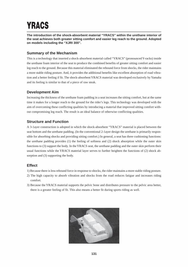
131
YRACSThe introduction of the shock-absorbent material “YRACS” within the urethane interior ofthe seat achieves both greater sitting comfort and easier leg reach to the ground. Adoptedon models including the “XJRI 300”.
Summary of the MechanismThis is a technology that inserted a shock-absorbent material called “YRACS” (pronounced Y-racks) inside
the urethane foam interior of the seat to produce the combined benefits of greater sitting comfort and easier
leg reach to the ground. Because this material eliminated the rebound force from shocks, the rider maintains
a more stable riding posture. And, it provides the additional benefits like excellent absorption of road vibra-
tion and a better feeling if fit. The shock-absorbent YRACS material was developed exclusively by Yamaha
and its feeling is similar to that of a piece of raw steak.
Development AimIncreasing the thickness of the urethane foam padding in a seat increases the sitting comfort, but at the same
time it makes for a longer reach to the ground for the rider’s legs. This technology was developed with the
aim of overcoming these conflicting qualities by introducing a material that improved sitting comfort with-
out compromising leg reach. The result is an ideal balance of otherwise conflicting qualities.
Structure and FunctionA 3-1ayer construction is adopted in which the shock-absorbent “YRACS” material is placed between the
seat bottom and the urethane padding. (In the conventional 2-1ayer design the urethane is primarily respon-
sible for absorbing shocks and providing sitting comfort.) In general, a seat has three cushioning functions:
the urethane padding provides (1) the feeling of softness and (2) shock absorption while the outer skin
functions to (3) support the body. In the YRACS seat, the urethane padding and the outer skin perform their
usual functions while the YRACS material layer serves to further heighten the functions of (2) shock ab-
sorption and (3) supporting the body.
Effect1) Because there is less rebound force in response to shocks, the rider maintains a more stable riding posture.
2) The high capacity to absorb vibration and shocks from the road reduces fatigue and increases riding
comfort.
3) Because the YRACS material supports the pelvic bone and distributes pressure to the pelvic area better,
there is a greater feeling of fit. This also means a better fit during sports riding as well.
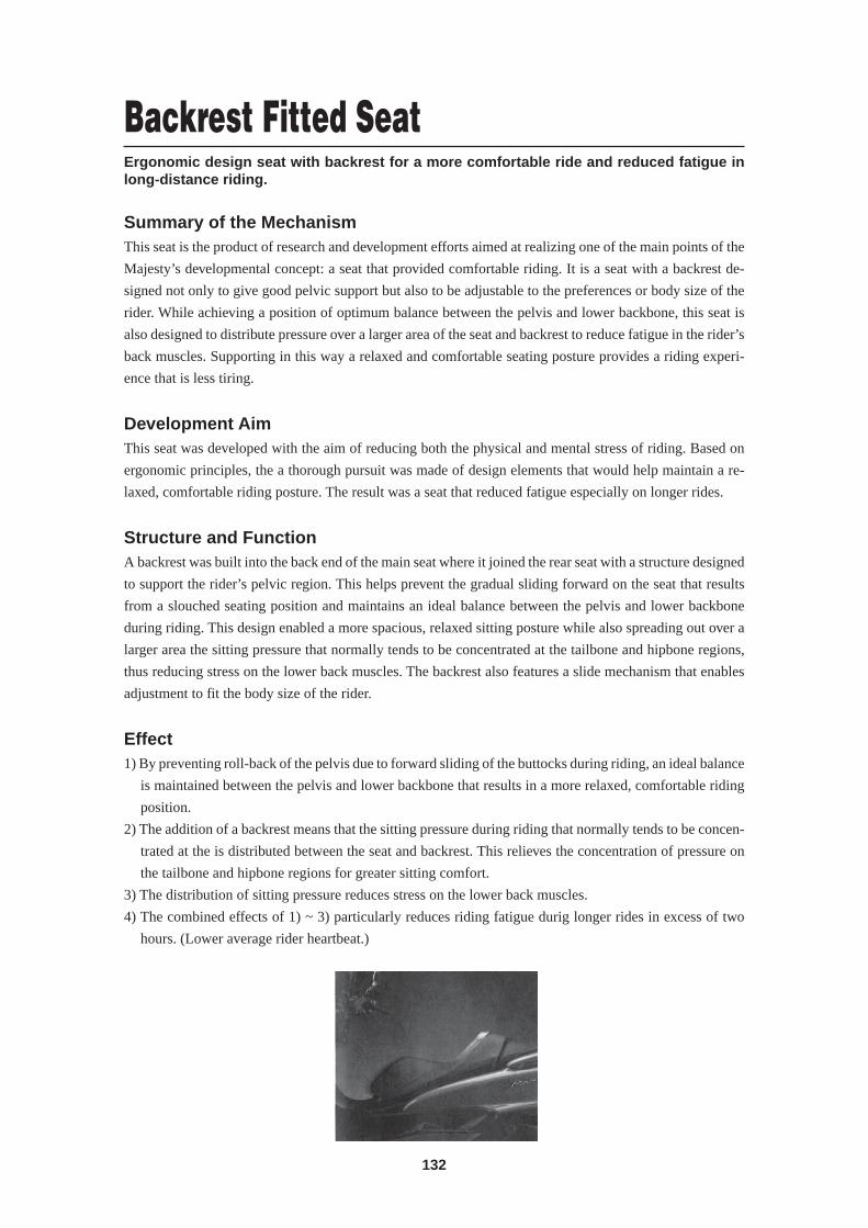
132
Backrest Fitted SeatErgonomic design seat with backrest for a more comfortable ride and reduced fatigue inlong-distance riding.
Summary of the MechanismThis seat is the product of research and development efforts aimed at realizing one of the main points of the
Majesty’s developmental concept: a seat that provided comfortable riding. It is a seat with a backrest de-
signed not only to give good pelvic support but also to be adjustable to the preferences or body size of the
rider. While achieving a position of optimum balance between the pelvis and lower backbone, this seat is
also designed to distribute pressure over a larger area of the seat and backrest to reduce fatigue in the rider’s
back muscles. Supporting in this way a relaxed and comfortable seating posture provides a riding experi-
ence that is less tiring.
Development AimThis seat was developed with the aim of reducing both the physical and mental stress of riding. Based on
ergonomic principles, the a thorough pursuit was made of design elements that would help maintain a re-
laxed, comfortable riding posture. The result was a seat that reduced fatigue especially on longer rides.
Structure and FunctionA backrest was built into the back end of the main seat where it joined the rear seat with a structure designed
to support the rider’s pelvic region. This helps prevent the gradual sliding forward on the seat that results
from a slouched seating position and maintains an ideal balance between the pelvis and lower backbone
during riding. This design enabled a more spacious, relaxed sitting posture while also spreading out over a
larger area the sitting pressure that normally tends to be concentrated at the tailbone and hipbone regions,
thus reducing stress on the lower back muscles. The backrest also features a slide mechanism that enables
adjustment to fit the body size of the rider.
Effect1) By preventing roll-back of the pelvis due to forward sliding of the buttocks during riding, an ideal balance
is maintained between the pelvis and lower backbone that results in a more relaxed, comfortable riding
position.
2) The addition of a backrest means that the sitting pressure during riding that normally tends to be concen-
trated at the is distributed between the seat and backrest. This relieves the concentration of pressure on
the tailbone and hipbone regions for greater sitting comfort.
3) The distribution of sitting pressure reduces stress on the lower back muscles.
4) The combined effects of 1) ~ 3) particularly reduces riding fatigue durig longer rides in excess of two
hours. (Lower average rider heartbeat.)
Engine Related Terms
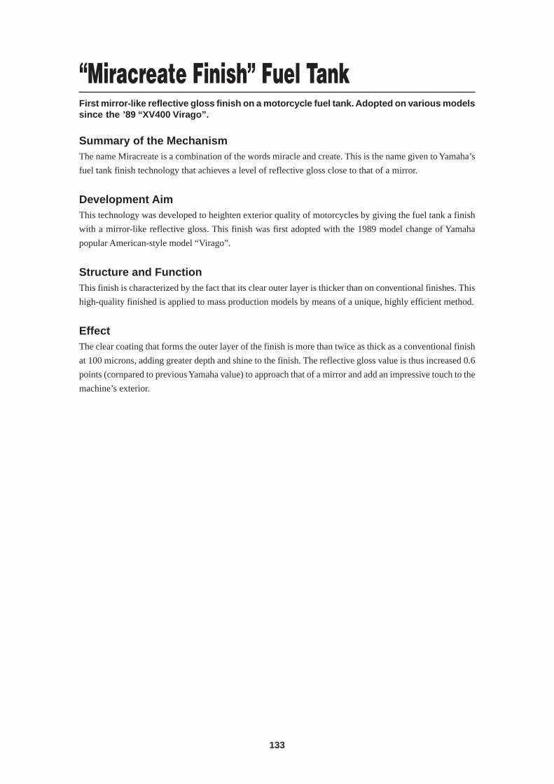
133
“Miracreate Finish” Fuel TankFirst mirror-like reflective gloss finish on a motorcycle fuel tank. Adopted on various modelssince the ’89 “XV400 Virago”.
Summary of the MechanismThe name Miracreate is a combination of the words miracle and create. This is the name given to Yamaha’s
fuel tank finish technology that achieves a level of reflective gloss close to that of a mirror.
Development AimThis technology was developed to heighten exterior quality of motorcycles by giving the fuel tank a finish
with a mirror-like reflective gloss. This finish was first adopted with the 1989 model change of Yamaha
popular American-style model “Virago”.
Structure and FunctionThis finish is characterized by the fact that its clear outer layer is thicker than on conventional finishes. This
high-quality finished is applied to mass production models by means of a unique, highly efficient method.
EffectThe clear coating that forms the outer layer of the finish is more than twice as thick as a conventional finish
at 100 microns, adding greater depth and shine to the finish. The reflective gloss value is thus increased 0.6
points (cornpared to previous Yamaha value) to approach that of a mirror and add an impressive touch to the
machine’s exterior.
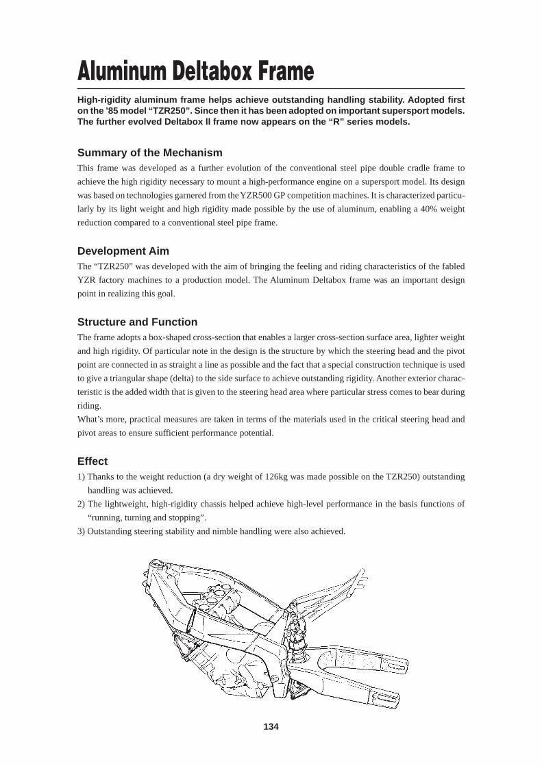
134
Aluminum Deltabox FrameHigh-rigidity aluminum frame helps achieve outstanding handling stability. Adopted firston the ’85 model “TZR250”. Since then it has been adopted on important supersport models.The further evolved Deltabox ll frame now appears on the “R” series models.
Summary of the MechanismThis frame was developed as a further evolution of the conventional steel pipe double cradle frame to
achieve the high rigidity necessary to mount a high-performance engine on a supersport model. Its design
was based on technologies garnered from the YZR500 GP competition machines. It is characterized particu-
larly by its light weight and high rigidity made possible by the use of aluminum, enabling a 40% weight
reduction compared to a conventional steel pipe frame.
Development AimThe “TZR250” was developed with the aim of bringing the feeling and riding characteristics of the fabled
YZR factory machines to a production model. The Aluminum Deltabox frame was an important design
point in realizing this goal.
Structure and FunctionThe frame adopts a box-shaped cross-section that enables a larger cross-section surface area, lighter weight
and high rigidity. Of particular note in the design is the structure by which the steering head and the pivot
point are connected in as straight a line as possible and the fact that a special construction technique is used
to give a triangular shape (delta) to the side surface to achieve outstanding rigidity. Another exterior charac-
teristic is the added width that is given to the steering head area where particular stress comes to bear during
riding.
What’s more, practical measures are taken in terms of the materials used in the critical steering head and
pivot areas to ensure sufficient performance potential.
Effect1) Thanks to the weight reduction (a dry weight of 126kg was made possible on the TZR250) outstanding
handling was achieved.
2) The lightweight, high-rigidity chassis helped achieve high-level performance in the basis functions of
“running, turning and stopping”.
3) Outstanding steering stability and nimble handling were also achieved.