Embed Size (px)
Citation preview
The Heteronuclear Single-Quantum Correlation (HSQC) Experiment:Vectors versus Product OperatorsKaren de la Vega-Hernandez† and Manuel Antuch*,‡
†Departamento de Química, Tecnología y Control de Medicamentos, Instituto de Farmacia y Alimentos, Universidad de La Habana,La Coronela, La Lisa, CP 13600, La Habana, Cuba‡Departamento de Química Física, Facultad de Química, Universidad de La Habana, Vedado, CP 10400, La Habana, Cuba
*S Supporting Information
ABSTRACT: A vectorial representation of the full sequence of eventsoccurring during the 2D-NMR heteronuclear single-quantum correlation(HSQC) experiment is presented. The proposed vectorial representationconveys an understanding of the magnetization evolution during the HSQCpulse sequence for those who have little or no quantum mechanicalbackground. This vectorial depiction is compared to results from the productoperator formalism, and thus uncovers several parallelisms and subtledifferences between both models. This approach permits a nice introductionto product operators at a level comprehensible to advanced upper-divisionundergraduate and graduate students without the use of the spin-densitymatrix.
KEYWORDS: Upper-Division Undergraduate, Graduate Education/Research, Physical Chemistry, Analogies/Transfer,NMR Spectroscopy
■ INTRODUCTION
Nuclear magnetic resonance (NMR) is a core educational issuein chemistry. Many papers have been published in theeducational literature dealing with NMR for structureelucidation,1−12 reviews of books and media,13,14 and otherpractical applications.15−20 However, very few deal with thetheory behind spin evolution,21,22 which is ultimatelyresponsible for the appearance of NMR spectra.Indeed, why two-dimensional nuclear magnetic resonance
(2D-NMR) spectra look as they do has always been hard toexplain. As the queen of the microworld, quantum mechanicshas been successfully employed to treat complex multiple-pulseNMR techniques. One of the quantum mechanical proceduresto predict the appearance of 2D-NMR spectra is the productoperator formalism.23−28 However, as was pointed out in thisJournal,21 teaching product operators (PO) has not been part ofundergraduate curricula mostly because it needs to bedeveloped from the spin-density matrix. We adhere to theopinion that PO might be satisfactorily introduced by takingthe intuitive vector model as the starting point.21 Even thoughthe simple vector model might sacrifice the most interestingand subtle features of 2D-NMR, it is undoubtedly usefulbecause it provides visual and comfortable representations, andit is very intuitive for those who have little background inquantum mechanics. Consequently, the vector model couldserve as bridge toward more rigorous explanations.Among multiple-pulse NMR experiments, the heteronuclear
single-quantum correlation (HSQC) experiment has mostlybeen approached using quantum mechanics.29−34 However,HSQC is a good candidate for a vectorial illustration for two
reasons: (i) its heteronuclear nature permits treating theevolution of carbon and proton magnetizations independently;and (ii) even though multiple quantum coherence appearsduring the experiment, it may be ignored at a basic level.33
Herein we present a vectorial depiction of the full sequenceof events occurring during the HSQC experiment. Thisrepresentation allows a full understanding of the appearanceof the resulting spectrum for those who are novices in 2D-NMR. The further comparison with PO results allows aninteresting pedagogical link between both models, and alsogives a nice introduction to the meaning of PO. This approachcould be beneficial in courses dealing with advanced organicchemistry, biophysical chemistry, and other graduate oradvanced undergraduate courses concerning NMR.
■ GENERAL STRUCTURE OF 2D-NMR EXPERIMENTSAll 2D-NMR experiments contain four well-defined stages: (i)preparation; (ii) evolution; (iii) mixing; and (iv) detection.Preparation and mixing stages comprise pulse sequences ordelay times that vary depending on the nature of theexperiment. The detection period is entirely analogous tothat in one-dimensional techniques, during which thespectrometer detects a free induction decay (FID) with allinformation saved in a frequency dimension known as F2. Theother dimension is generated during the evolution period. Anyobservable, offset, heteronuclear or homonuclear couplings thatare not refocused during this period would be observed in theindirect frequency known as F1.
Article
pubs.acs.org/jchemeduc
© XXXX American Chemical Society andDivision of Chemical Education, Inc. A DOI: 10.1021/ed500575p
J. Chem. Educ. XXXX, XXX, XXX−XXX
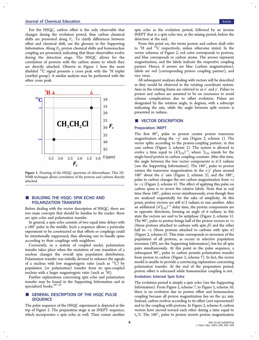
For the HSQC, carbon offset is the only observable thatchanges during the evolution period, thus carbon chemicalshifts are presented along F1. To clarify differences betweenoffset and chemical shift, see the glossary in the SupportingInformation. Along F2, proton chemical shifts and homonuclearcoupling are presented, indicating that these observables evolveduring the detection stage. The HSQC allows for thecorrelation of protons with the carbon atoms to which theyare directly attached. Observe in Figure 1 how the mostshielded 13C signal presents a cross peak with the 1H triplet(methyl group). A similar analysis may be performed with theother cross peak.
■ BUILDING THE HSQC: SPIN ECHO ANDPOLARIZATION TRANSFER
Before dealing with the vector description of HSQC, there aretwo main concepts that should be familiar to the reader: theseare spin echo and polarization transfer.In general, a spin echo consists of two equal time delays with
a 180° pulse in the middle. Such a sequence allows a particularexperiment to be constructed so that offsets or couplings couldbe intentionally suppressed, thus allowing one to handle spinsaccording to their couplings with neighbors.Conversely, in a system of coupled nuclei, polarization
transfer takes place when the excitation of one transition of anucleus changes the overall spin population distribution.Polarization transfer was initially devised to enhance the signalsof a nucleus with low magnetogyric ratio (such as 13C) bypopulation (or polarization) transfer from its spin-couplednucleus with a larger magnetogyric ratio (such as 1H).Further explanations concerning spin echo and polarization
transfer may be found in the Supporting Information and inspecialized books.30−33
■ GENERAL DESCRIPTION OF THE HSQC PULSESEQUENCE
The pulse sequence of the HSQC experiment is depicted at thetop of Figure 2. The preparation stage is an INEPT sequence,which incorporates a spin echo as well. Then comes another
spin echo as the evolution period, followed by an inverseINEPT that is a spin echo too, as the mixing period, before thedetection at the end.From this point on, the terms proton and carbon shall refer
to 1H and 13C respectively, unless otherwise stated. In thevector schemes of Figure 2, red color corresponds to protons,and blue corresponds to carbon atoms. The arrows representmagnetization, and the labels indicate the respective couplingpartner. Hence, if arrows are blue (carbon magnetization),labels are red (corresponding proton coupling partner), andvice versa.All subsequent analyses dealing with vectors will be described
as they would be observed in the rotating coordinate system.Axes in the rotating frame are referred to as x′ and y′. Pulses toproton and carbon are assumed to be on resonance to avoidscheme complications due to offset evolution. Pulses aredesignated by the rotation angle, in degrees, with a subscriptindicating the axis, while the angle between split vectors ispresented in radians.
■ VECTOR DESCRIPTION
Preparation: INEPT
The first 90°x pulse to proton creates proton transversemagnetization along the −y′ axis (Figure 2, scheme 1). Thevector splits according to the proton-coupling partner, in thiscase carbon (Figure 2, scheme 2). The system is allowed toevolve a time equal to (41JCH)
−1, where 1JCH stands for thesingle bond proton to carbon coupling constant. After this time,the angle between the two vector components is π/2 radians(see the Supporting Information). The 180°x pulse to protonrotates the transverse magnetization in the x′y′ plane around180° about the x′ axis (Figure 2, scheme 3), and the 180°xpulse to carbon changes the net carbon magnetization from +zto −z (Figure 2, scheme 4). The effect of applying this pulse oncarbon spins is to invert the relative labels. Note that in realtime these 180°x pulses occur simultaneously, even though theyare analyzed sequentially for the sake of simplicity. At thispoint, proton vectors are still π/2 radians to one another. Afteran additional (41JCH)
−1 delay time, the proton components arein opposite directions, forming an angle of π radians; in thisstate the vectors are said to be antiphase (Figure 2, scheme 5).The 90°y pulse to proton brings half of the proton vectors to +z(those protons attached to carbons with spin β) and the otherhalf to −z (those protons attached to carbons with spin α)(Figure 2, scheme 6). This state corresponds to inversion of thepopulation of all protons, as occurs in selective populationinversion (SPI, see the Supporting Information), but for all spinpairs simultaneously. At this point in the pulse sequence, asubsequent 90°x pulse to carbon permits polarization transferfrom proton to carbon (Figure 2, scheme 7). In fact, the vectormodel is unable to provide a convincing explanation concerningpolarization transfer. At the end of the preparation period,proton offset is refocused while homonuclear coupling is not.Evolution: Internal Spin Echo
The evolution period is simply a spin echo (see the SupportingInformation). From Figure 2, scheme 7, to Figure 2, scheme 10,there is no evolution due to proton offset and homonuclearcoupling because all proton magnetization lies on the ±z axis.Instead, carbon evolves according to its offset (not represented)and to the coupling with protons. In Figure 2, scheme 8, carbonvectors have moved toward each other during a time equal tot1/2. The 180°x pulse to proton inverts proton magnetization
Figure 1. Drawing of the HSQC spectrum of chloroethane. This 2D-NMR technique allows correlation of the protons and carbons directlyattached.
Journal of Chemical Education Article
DOI: 10.1021/ed500575pJ. Chem. Educ. XXXX, XXX, XXX−XXX
B
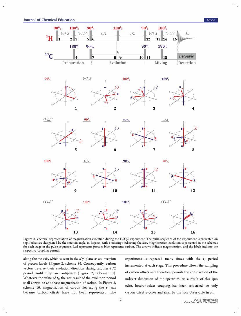
along the ±z axis, which is seen in the x′y′ plane as an inversionof proton labels (Figure 2, scheme 9). Consequently, carbonvectors reverse their evolution direction during another t1/2period, until they are antiphase (Figure 2, scheme 10).Whatever the value of t1, the net result of the evolution periodshall always be antiphase magnetization of carbon. In Figure 2,scheme 10, magnetization of carbon lies along the y′ axisbecause carbon offsets have not been represented. The
experiment is repeated many times with the t1 period
incremented at each stage. This procedure allows the sampling
of carbon offsets and, therefore, permits the construction of the
indirect dimension of the spectrum. As a result of this spin
echo, heteronuclear coupling has been refocused, so only
carbon offset evolves and shall be the sole observable in F1.
Figure 2. Vectorial representation of magnetization evolution during the HSQC experiment. The pulse sequence of the experiment is presented ontop. Pulses are designated by the rotation angle, in degrees, with a subscript indicating the axis. Magnetization evolution is presented in the schemesfor each stage in the pulse sequence. Red represents proton; blue represents carbon. The arrows indicate magnetization, and the labels indicate therespective coupling partner.
Journal of Chemical Education Article
DOI: 10.1021/ed500575pJ. Chem. Educ. XXXX, XXX, XXX−XXX
C
Mixing: Inverse INEPT
The 90°x pulse to carbon brings carbon magnetization to the±z axis (Figure 2, scheme 11). Note that this spin state issimilar to that represented in Figure 2, scheme 6, but in thiscase there are proton magnetization on ±z and inversion ofcarbon population. A subsequent 90°x pulse applied to protonallows polarization transfer back from carbon to proton (Figure2, scheme 12). Indeed, this is the same as in the INEPT, but inreverse. Now transverse magnetization is due to protons andshall evolve according to heteronuclear coupling. Protonvectors precess a period equal to (41JCH)
−1 until the anglebetween both components is π/2 radians (Figure 2, scheme13). The 180°x pulse to proton interchanges the vectors(Figure 2, scheme 14), and the simultaneous 180°x pulse tocarbon changes carbon labels (Figure 2, scheme 15). Then,proton vectors continue to close another time equal to(41JCH)
−1 until both components are in-phase (Figure 2,scheme 16).Finally, proton offset and homonuclear coupling are
observed in F2 during the detection period. The procedure tosuppress the resonances of those protons attached to 12C hasbeen described in the literature.31,33
■ COMPARISON WITH PRODUCT OPERATORS
Representation of Spin States with Product Operators
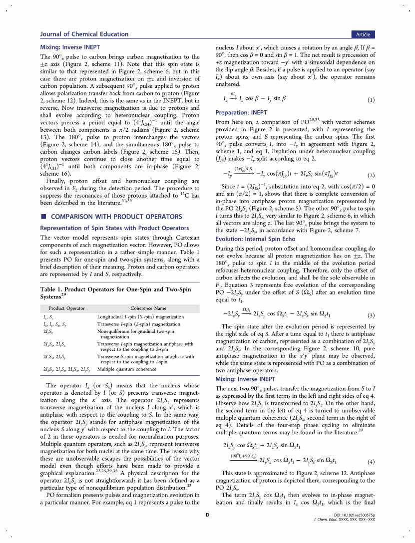
The vector model represents spin states through Cartesiancomponents of each magnetization vector. However, PO allowsfor such a representation in a rather simple manner. Table 1presents PO for one-spin and two-spin systems, along with abrief description of their meaning. Proton and carbon operatorsare represented by I and S, respectively.
The operator Ix (or Sx) means that the nucleus whoseoperator is denoted by I (or S) presents transverse magnet-ization along the x′ axis. The operator 2IxSz representstransverse magnetization of the nucleus I along x′, which isantiphase with respect to the coupling to S. In the same way,the operator 2IzSy stands for antiphase magnetization of thenucleus S along y′ with respect to the coupling to I. The factorof 2 in these operators is needed for normalization purposes.Multiple quantum operators, such as 2IxSy, represent transversemagnetization for both nuclei at the same time. The reason whythese are unobservable escapes the possibilities of the vectormodel even though efforts have been made to provide agraphical explanation.23,25,29,35 A physical description for theoperator 2IzSz is not straightforward; it has been defined as aparticular type of nonequilibrium population distribution.33
PO formalism presents pulses and magnetization evolution ina particular manner. For example, eq 1 represents a pulse to the
nucleus I about x′, which causes a rotation by an angle β. If β =90°, then cos β = 0 and sin β = 1. The net result is precession of+z magnetization toward −y′ with a sinusoidal dependence onthe flip angle β. Besides, if a pulse is applied to an operator (sayIx) about its own axis (say about x′), the operator remainsunaltered.
β β⎯→⎯ −β
I I Icos sinzI
z yx
(1)
Preparation: INEPT
From here on, a comparison of PO29,33 with vector schemesprovided in Figure 2 is presented, with I representing theproton spins, and S representing the carbon spins. The first90°x pulse converts Iz into −Iy in agreement with Figure 2,scheme 1, and eq 1. Evolution under heteronuclear coupling(JIS) makes −Iy split according to eq 2.
π π− ⎯ →⎯⎯⎯⎯⎯⎯⎯⎯ − +π
I I J t I S J tcos( ) 2 sin( )yJ I S
y IS x z IS
(2 )IS z z
(2)
Since t = (2JIS)−1, substitution into eq 2, with cos(π/2) = 0
and sin (π/2) = 1, shows that there is complete conversion ofin-phase into antiphase proton magnetization represented bythe PO 2IxSz (Figure 2, scheme 5). The other 90°x pulse to spinI turns this to 2IzSz, very similar to Figure 2, scheme 6, in whichall vectors are along z. The last 90°x pulse brings the system tothe state −2IzSy, in accordance with Figure 2, scheme 7.Evolution: Internal Spin Echo
During this period, proton offset and homonuclear coupling donot evolve because all proton magnetization lies on ±z. The180°x pulse to spin I in the middle of the evolution periodrefocuses heteronuclear coupling. Therefore, only the offset ofcarbon affects the evolution, and shall be the sole observable inF1. Equation 3 represents free evolution of the correspondingPO −2IzSy under the offset of S (ΩS) after an evolution timeequal to t1.
− ⎯ →⎯⎯ Ω − ΩΩ
I S I S t I S t2 2 cos 2 sinz yt
z y S z x S1 1S 1
(3)
The spin state after the evolution period is represented bythe right side of eq 3. After a time equal to t1 there is antiphasemagnetization of carbon, represented as a combination of 2IzSxand 2IzSy. In the corresponding Figure 2, scheme 10, pureantiphase magnetization in the x′y′ plane may be observed,while the same state is represented with PO as a combination oftwo antiphase operators.Mixing: Inverse INEPT
The next two 90°x pulses transfer the magnetization from S to Ias expressed by the first terms in the left and right sides of eq 4.Observe how 2IzSy is transformed to 2IySz. On the other hand,the second term in the left of eq 4 is turned to unobservablemultiple quantum coherence (2IySx, second term in the right ofeq 4). Details of the four-step phase cycling to eliminatemultiple quantum terms may be found in the literature.29
Ω − Ω
⎯ →⎯⎯⎯⎯⎯⎯⎯⎯⎯⎯⎯⎯ Ω − Ω+
I S t I S t
I S t I S t
2 cos 2 sin
2 cos 2 sin
z y S z x S
I Sy z S y x S
1 1
(90 90 )1 1
x x0 0
(4)
This state is approximated to Figure 2, scheme 12. Antiphasemagnetization of proton is depicted there, corresponding to thePO 2IySz.The term 2IySz cos ΩSt1 then evolves to in-phase magnet-
ization and finally results in Ix cos ΩSt1, which is the final
Table 1. Product Operators for One-Spin and Two-SpinSystems29
Product Operator Coherence Name
Iz, Sz Longitudinal I-spin (S-spin) magnetizationIx, Iy, Sx, Sy Transverse I-spin (S-spin) magnetization2IzSz Nonequilibrium longitudinal two-spin
magnetization2IxSz, 2IySz Transverse I-spin magnetization antiphase with
respect to the coupling to S-spin2IzSx, 2IzSy Transverse S-spin magnetization antiphase with
respect to the coupling to I-spin2IxSy, 2IySx, 2IxSx, 2IySy Multiple quantum coherence
Journal of Chemical Education Article
DOI: 10.1021/ed500575pJ. Chem. Educ. XXXX, XXX, XXX−XXX
D
observable in the FID in F2. Nicely, the final result is protontransverse magnetization along x′ (Ix) evolving at the offset ofcarbon (ΩS), giving rise to the characteristic cross peak betweencarbons and the directly attached protons. There are twodifferences with the corresponding Figure 2, scheme 16: (i)proton magnetization lies along −x′; and (ii) there is no way ofrepresenting proton magnetization evolving at the offset ofcarbon. The spectrum contains an in-phase doublet in F2centered at the offset of proton, and in F1 at the offset ofcarbon.
■ MULTIPLE QUANTUM COHERENCE: WHAT DOTHE VECTORS SAY?
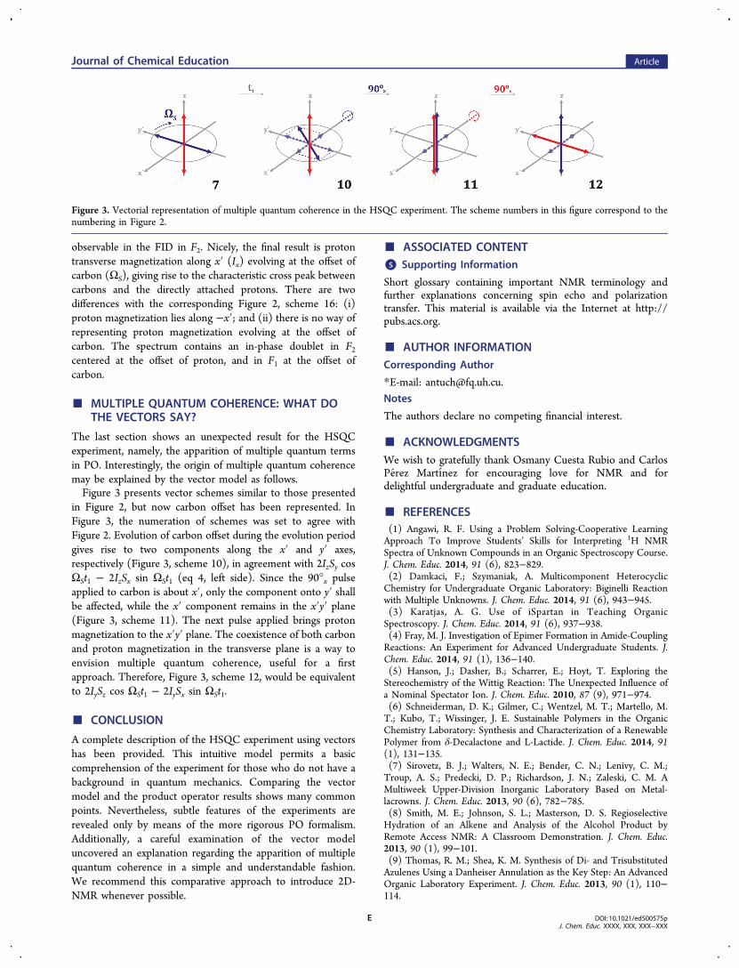
The last section shows an unexpected result for the HSQCexperiment, namely, the apparition of multiple quantum termsin PO. Interestingly, the origin of multiple quantum coherencemay be explained by the vector model as follows.Figure 3 presents vector schemes similar to those presented
in Figure 2, but now carbon offset has been represented. InFigure 3, the numeration of schemes was set to agree withFigure 2. Evolution of carbon offset during the evolution periodgives rise to two components along the x′ and y′ axes,respectively (Figure 3, scheme 10), in agreement with 2IzSy cosΩSt1 − 2IzSx sin ΩSt1 (eq 4, left side). Since the 90°x pulseapplied to carbon is about x′, only the component onto y′ shallbe affected, while the x′ component remains in the x′y′ plane(Figure 3, scheme 11). The next pulse applied brings protonmagnetization to the x′y′ plane. The coexistence of both carbonand proton magnetization in the transverse plane is a way toenvision multiple quantum coherence, useful for a firstapproach. Therefore, Figure 3, scheme 12, would be equivalentto 2IySz cos ΩSt1 − 2IySx sin ΩSt1.
■ CONCLUSION
A complete description of the HSQC experiment using vectorshas been provided. This intuitive model permits a basiccomprehension of the experiment for those who do not have abackground in quantum mechanics. Comparing the vectormodel and the product operator results shows many commonpoints. Nevertheless, subtle features of the experiments arerevealed only by means of the more rigorous PO formalism.Additionally, a careful examination of the vector modeluncovered an explanation regarding the apparition of multiplequantum coherence in a simple and understandable fashion.We recommend this comparative approach to introduce 2D-NMR whenever possible.
■ ASSOCIATED CONTENT*S Supporting Information
Short glossary containing important NMR terminology andfurther explanations concerning spin echo and polarizationtransfer. This material is available via the Internet at http://pubs.acs.org.
■ AUTHOR INFORMATIONCorresponding Author
*E-mail: [email protected].
Notes
The authors declare no competing financial interest.
■ ACKNOWLEDGMENTSWe wish to gratefully thank Osmany Cuesta Rubio and CarlosPerez Martınez for encouraging love for NMR and fordelightful undergraduate and graduate education.
■ REFERENCES(1) Angawi, R. F. Using a Problem Solving-Cooperative LearningApproach To Improve Students’ Skills for Interpreting 1H NMRSpectra of Unknown Compounds in an Organic Spectroscopy Course.J. Chem. Educ. 2014, 91 (6), 823−829.(2) Damkaci, F.; Szymaniak, A. Multicomponent HeterocyclicChemistry for Undergraduate Organic Laboratory: Biginelli Reactionwith Multiple Unknowns. J. Chem. Educ. 2014, 91 (6), 943−945.(3) Karatjas, A. G. Use of iSpartan in Teaching OrganicSpectroscopy. J. Chem. Educ. 2014, 91 (6), 937−938.(4) Fray, M. J. Investigation of Epimer Formation in Amide-CouplingReactions: An Experiment for Advanced Undergraduate Students. J.Chem. Educ. 2014, 91 (1), 136−140.(5) Hanson, J.; Dasher, B.; Scharrer, E.; Hoyt, T. Exploring theStereochemistry of the Wittig Reaction: The Unexpected Influence ofa Nominal Spectator Ion. J. Chem. Educ. 2010, 87 (9), 971−974.(6) Schneiderman, D. K.; Gilmer, C.; Wentzel, M. T.; Martello, M.T.; Kubo, T.; Wissinger, J. E. Sustainable Polymers in the OrganicChemistry Laboratory: Synthesis and Characterization of a RenewablePolymer from δ-Decalactone and L-Lactide. J. Chem. Educ. 2014, 91(1), 131−135.(7) Sirovetz, B. J.; Walters, N. E.; Bender, C. N.; Lenivy, C. M.;Troup, A. S.; Predecki, D. P.; Richardson, J. N.; Zaleski, C. M. AMultiweek Upper-Division Inorganic Laboratory Based on Metal-lacrowns. J. Chem. Educ. 2013, 90 (6), 782−785.(8) Smith, M. E.; Johnson, S. L.; Masterson, D. S. RegioselectiveHydration of an Alkene and Analysis of the Alcohol Product byRemote Access NMR: A Classroom Demonstration. J. Chem. Educ.2013, 90 (1), 99−101.(9) Thomas, R. M.; Shea, K. M. Synthesis of Di- and TrisubstitutedAzulenes Using a Danheiser Annulation as the Key Step: An AdvancedOrganic Laboratory Experiment. J. Chem. Educ. 2013, 90 (1), 110−114.
Figure 3. Vectorial representation of multiple quantum coherence in the HSQC experiment. The scheme numbers in this figure correspond to thenumbering in Figure 2.
Journal of Chemical Education Article
DOI: 10.1021/ed500575pJ. Chem. Educ. XXXX, XXX, XXX−XXX
E
(10) Chou, S.-C.; Mercier, J. E.; Wilson, K. A.; Beck, J. J. CompleteProton and Carbon Assignment of (+)-Catechin via One- and Two-Dimensional Nuclear Magnetic Resonance (NMR) Analysis: A Hands-on Learning Experiment for Upper-Division Undergraduate ChemistryStudents. Chem. Educ. 2006, 11 (1), 15−22.(11) Cooke, J. Preparation and NMR Spectroscopy of a Series ofIridium Compounds with Interesting Ligand Combinations: AnAdvanced Undergraduate Experiment in Organometallic Chemistry.Chem. Educ. 2008, 13 (6), 353−357.(12) Wilson, K. A.; Beck, J. J. Complete Proton and CarbonAssignment of Triclosan via One- and Two-Dimensional NuclearMagnetic Resonance Analysis. Chem. Educ. 2007, 12 (5), 338−342.(13) Minch, M. J. Spin Choreography: Basic Steps in HighResolution NMR (Freeman, Ray). J. Chem. Educ. 1998, 75 (2), 155.(14) Ward, R. L. A Complete Introduction to Modern NMRSpectroscopy (Macomber, Rodger S.). J. Chem. Educ. 1999, 76 (4),473.(15) Dawsey, A. C.; Hathaway, K. L.; Kim, S.; Williams, T. J.Introductory Chemistry: A Molar Relaxivity Experiment in the HighSchool Classroom. J. Chem. Educ. 2013, 90 (7), 922−925.(16) Guegan, J.-P.; Daniellou, R. An Introduction to Drug Discoveryby Probing Protein−Substrate Interactions Using Saturation TransferDifference-Nuclear Magnetic Interactions Using Saturation TransferDifference-Nuclear Magnetic Resonance (STD-NMR). J. Chem. Educ.2012, 89 (8), 1071−1073.(17) Kehlbeck, J. D.; Slack, C.; Turnbull, M. T.; Kohler, S. J.Exploring the Hydrolysis of Sucrose by Invertase Using NuclearMagnetic Resonance Spectroscopy: A Flexible Package of KineticExperiments. J. Chem. Educ. 2014, 91 (5), 734−738.(18) Bartle, K. D.; Dale, B. J.; Jones, D. W.; Maricic, S. NMRdetermination of the magnetic susceptibility of iron proteins: Anundergraduate experiment. Biochem. Educ. 1975, 3 (3), 48−49.(19) Kayastha, A. M.; Prabhakar, P.; Malhotra, O. P. Advances in themolecular recognition of DNA - A step towards therapeutic drugdesign. Biochem. Educ. 1995, 23 (2), 56−64.(20) Sandusky, P. O. Expansion of the Classic Acetylacetone PhysicalChemistry Laboratory NMR Experiment: Correlation of the Enol−Keto Equilibrium Position with the Solvent Dipole Moment. J. Chem.Educ. 2014, 91 (5), 739−742.(21) Spiese, C. E. A simplified approach to product operatorformalism. J. Chem. Educ. 2004, 81 (1), 134.(22) Kinnun, J. J.; Leftin, A.; Brown, M. F. Solid-State NMRSpectroscopy for the Physical Chemistry Laboratory. J. Chem. Educ.2013, 90 (1), 123−128.(23) Donne, D. G.; Gorenstein, D. G. A Pictorial Representation ofProduct Operator Formalism: Nonclassical Vector Diagrams forMultidimensional NMR. Concepts Magn. Reson. 1997, 9 (2), 95−111.(24) Goldenberg, D. P. The Product Operator Formalism: A Physicaland Graphical Interpretation. Concepts Magn. Reson., Part A 2010, 36A(2), 49−83.(25) Podkorytov, I. S. Multipulse NMR Part II. Product OperatorDescription of the Weakly Coupled, Two-Spin-1/2 System. ConceptsMagn. Reson. 1997, 9 (3), 117−137.(26) Skinner, T. E.; Bendall, M. R. J-Coupling and Chemical-ShiftEvolution During I-Spin Irradiation of ImSn Systems: Product OperatorSolutions and Applications. Concepts Magn. Reson. 2002, 14 (5), 287−307.(27) Sørensen, O. W.; Eich, G. W.; Levitt, M. H.; Bodenhausen, G.;Ernst, R. R. Product operator formalism for the description of NMRpulse experiments. Prog. Nucl. Magn. Reson. Spectrosc. 1983, 16, 163−192.(28) Stait-Gardner, T.; Price, W. S. A Physical Interpretation ofProduct Operator Terms. Concepts Magn. Reson., Part A 2009, 34A(6), 322−356.(29) Mandal, P. K.; Majumdar, A. A Comprehensive Discussion ofHSQC and HMQC Pulse Sequences. Concepts Magn. Reson., Part A2004, 20A (1), 1−23.(30) Becker, E. D. High Resolution NMR Theory and ChemicalApplications, 3rd ed.; Academic Press: New York, 2000.
(31) Claridge, T. D. W. High-Resolution NMR Techniques in OrganicChemistry, 2nd ed.; Elsevier: New York, 2009.(32) Jacobsen, N. E. NMR Spectroscopy Explained. Simplified Theory,Applications and Examples for Organic Chemistry and Structural Biology;John Wiley & Sons, Inc.: Hoboken, NJ, 2007.(33) Keeler, J. Understanding NMR Spectroscopy; John Wiley & Sons,Inc.: Oxford, 2002.(34) Levitt, M. H. Spin Dynamics. Basics of Nuclear MagneticResonance, 2nd ed.; John Wiley & Sons, Ltd: West Sussex, England,2008.(35) Freeman, R. A Physical Picture of Multiple-QuantumCoherence. Concepts Magn. Reson. 1998, 10 (1), 63−84.
Journal of Chemical Education Article
DOI: 10.1021/ed500575pJ. Chem. Educ. XXXX, XXX, XXX−XXX
F